

Page 1
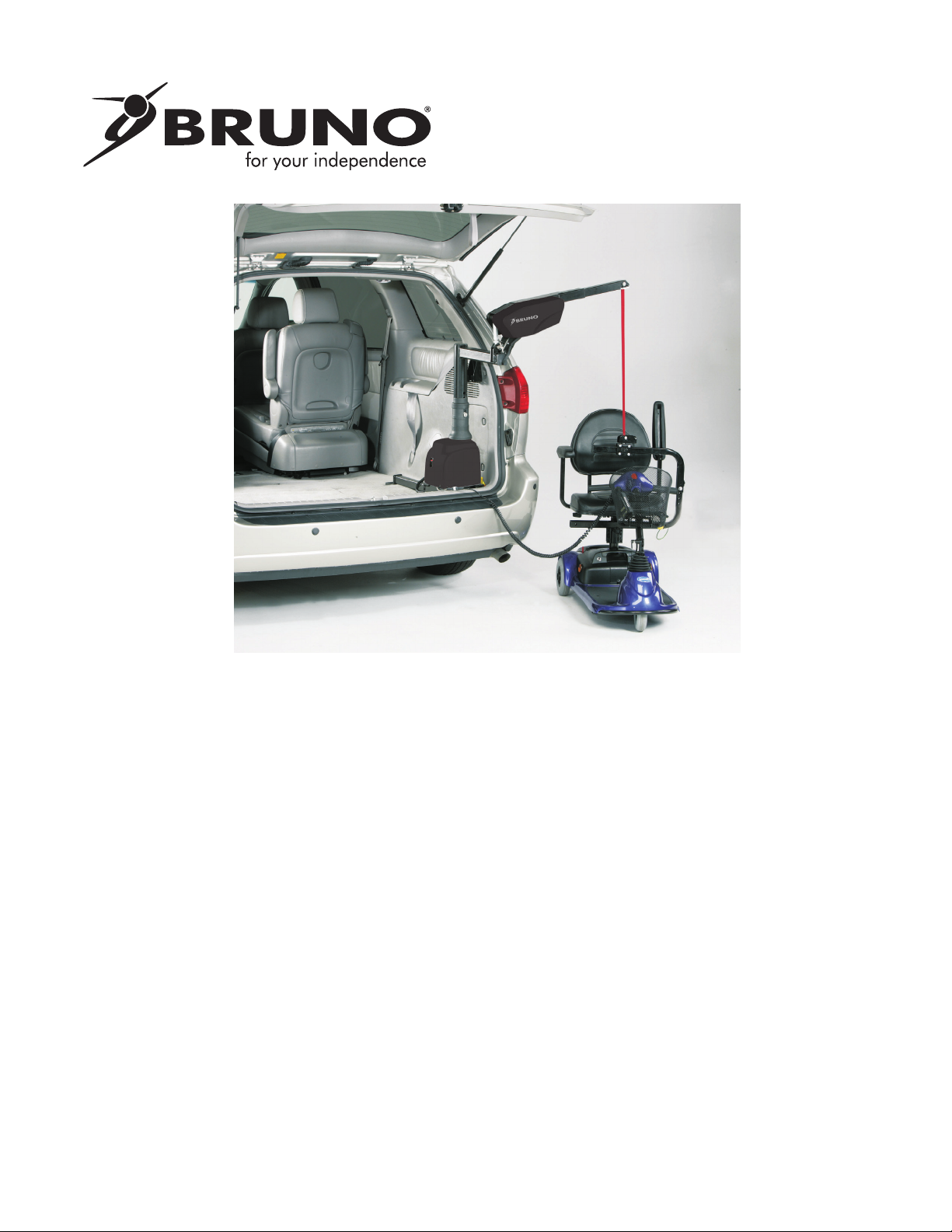
CURB-SIDER®
VSL-6000 AND 6900
OPERATOR’S
MANUAL
04-16-2019
P/N 6000/6900-UK-O
Page 2
ank you for purchasing a Bruno VSL-6000/6900 Curb-Sider® lift..
e information contained in this manual is provided with your safety in mind. Please read and
follow the instructions to ensure safe and trouble-free operation.
roughout this manual, safety precautions are provided to identify potentially hazardous situations and to
advise how to avoid them.
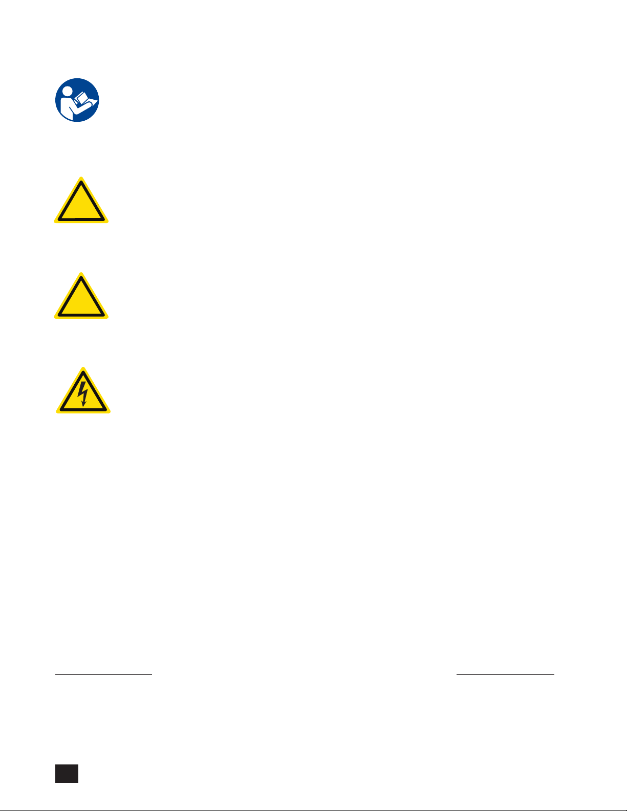
WARNING: Indicates a potentially hazardous situation that, if not avoided, could cause serious
bodily injury and/or property damage.
!
CAUTION: Indicates a potentially hazardous situation that, if not avoided, could cause damage
to the lift, vehicle and/or moderate injury.
!
CAUTION: Indicates a potentially hazardous electrical situation that, if not avoided, could cause
damage to the lift, vehicle and/or moderate injury.
NOTE: Directions that make it easier to install or operate the lift.
Authorized EU Agent:
ASCIER SAS
11-13 Rue Charles Cordier
ZA Parc de Bel Air
77164 Ferrières-en-Brie
FRANCE
Authorized UK Agent:
BRUNO UK LTD.
Unit 5, Millennium Court
Clayhill Industrial Park
Neston, Wirral CH64 3UZ
UNITED KINGDOM
VSL-6000/6900UK Operator’s 04/16/201
2
©BRUNO
Page 3

TABLE OF CONTENTS
1.0 For your safety ............................................ 4
2.0 Product registration form ..................................... 5
3.0 CE and Maximum Load Rating Information .................6
4.0 Docking devices ...................................7-8
5.0 Loading a mobility device ...........................9-11
6.0 Unloading a mobility device ........................12-13
7.0 VSL-6900: Special operating instructions ..............14-15
8.0 Optional fold-down quick release pins ................16-17
9.0 Emergency backup operation .......................18-19
10.0 Maintenance and troubleshooting ......................20
©BRUNO
VSL-6000/6900UK Operator’s 04/16/2019
3
Page 4

1.0 FOR YOUR SAFETY
• e Curb-Sider® is designed to lift mobility
devices weighing up to 400 lb (181 kg)
• Do not abuse or exceed the maximum lift
capacity indicated on the unit.
• Do not remove any guards or covers.
• Always be aware of surface conditions before
using the lift and take appropriate care.
• Park the vehicle on a horizontal, level surface.
Load and unload on as level a surface as
possible.
• Avoid unloading into vehicular trac.
• Read and understand the operating
instructions, and all safety precautions prior
to using the lift. Operate the lift several times
while the installer is available to answer
questions.
WARNING: Read vehicle manufacturers (OEM)
instructions about the vehicle’s
electrical system BEFORE working
on the vehicle. Vehicle OEMs
have model specic requirements
about battery disconnection when
performing work on a vehicle.
Disconnecting batteries incorrectly
or working on a vehicle with batteries
improperly in the circuit MAY cause
loss of vehicle data, damage vehicle
wiring system or even cause airbags
to deploy. is information can be
found in the VEHICLE OWNER’S
MANUAL or the VEHICLE REPAIR
GUIDE.
• Vehicle engine must be shut o, with
transmission set in park (parking brake
must be engaged on models with manual
transmission).
• Keep hands, ngers and feet away from moving
components during lift operation.
• Be sure the power source of the device being
lifted (scooter, power chair, wheelchair) is OFF
before attaching it to the lift.
VSL-6000/6900UK Operator’s 04/16/201
4
©BRUNO
Page 5
2.0 PRODUCT REGISTRATION FORM
We are pleased to provide you with this mobilityenhancing product.
e Product Registration Form is shipped in a
plastic bag with this manual. It is very important
that you ll out and return this form at your
earliest convenience so that we may complete the
warranty registration process for your unit.
e serial number is found on labels axed to the
manual, as well as on the unit itself.
Serial and model numbers must be provided
when ling a warranty claim, requesting service
or ordering parts. We encourage you to keep this
information readily available at all times.
Best wishes.
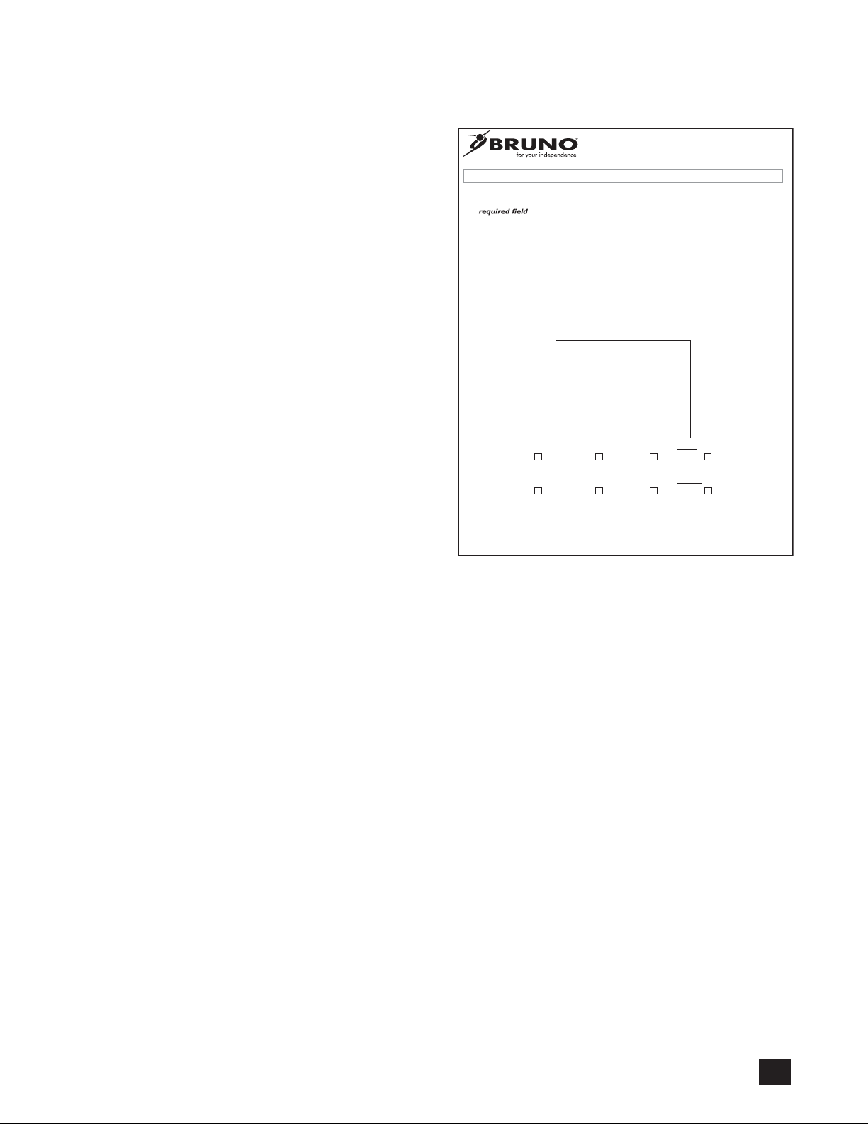
Product Registration Form
Please print in
Online registration available at http://www.bruno.com/warranty.html
Please be assured that Bruno does not share or sell the information you provide.
* =
*First Name ______________________________________________________ M.I._____
*Last Name _______________________________________________________________
*Street Address ________________________________________________Apt. No._____
*City _____________________________________________ *State/Province _________
*Zip/Postal Code ___________________________________________________________
Email Address _____________________________________________________________
Telephone No. _____________________________________________________________
Date of Purchase (mm/dd/yy) _________________________________________________
Dealer:Locate the Model No. and Serial
No. decal on the decal sheet
shipped with the unit and
place it here.
End-User: For faster registration,
please go to the website
shown above.
Model No.___________
*
Serial No._________________
Please rate your satisfaction with your Bruno dealer:
excellent good average poor
Please rate your satisfaction with your Bruno product:
excellent good average poor
Bruno reserves the right to use information indicated on this form in its online, video, audio and printed
©2013,2005 Bruno Independent Living Aids, Inc.®
SAMPLE
materials. Names will be abbreviated to ensure the privacy and anonymity of the individual.
CAPITAL
letters
P/N PROD REG STD
.
Rev. 02-18-2013
©BRUNO
VSL-6000/6900UK Operator’s 04/16/2019
5
Page 6
3.0 CE AND MAXIMUM LOAD RATING
!
e lift weight rating is the MAXIMUM load
rating. e maximum load rating for the specic
vehicle application has been determined during
the design of the mounting assembly. During
dealer installation, factors inherent to specic
applications including, but not limited to, vehicle
structure and condition, operating environment,
and customer ability may reduce the eective
weight rating. e structure of the lift itself is
NOT a factor in establishment of load ratings.
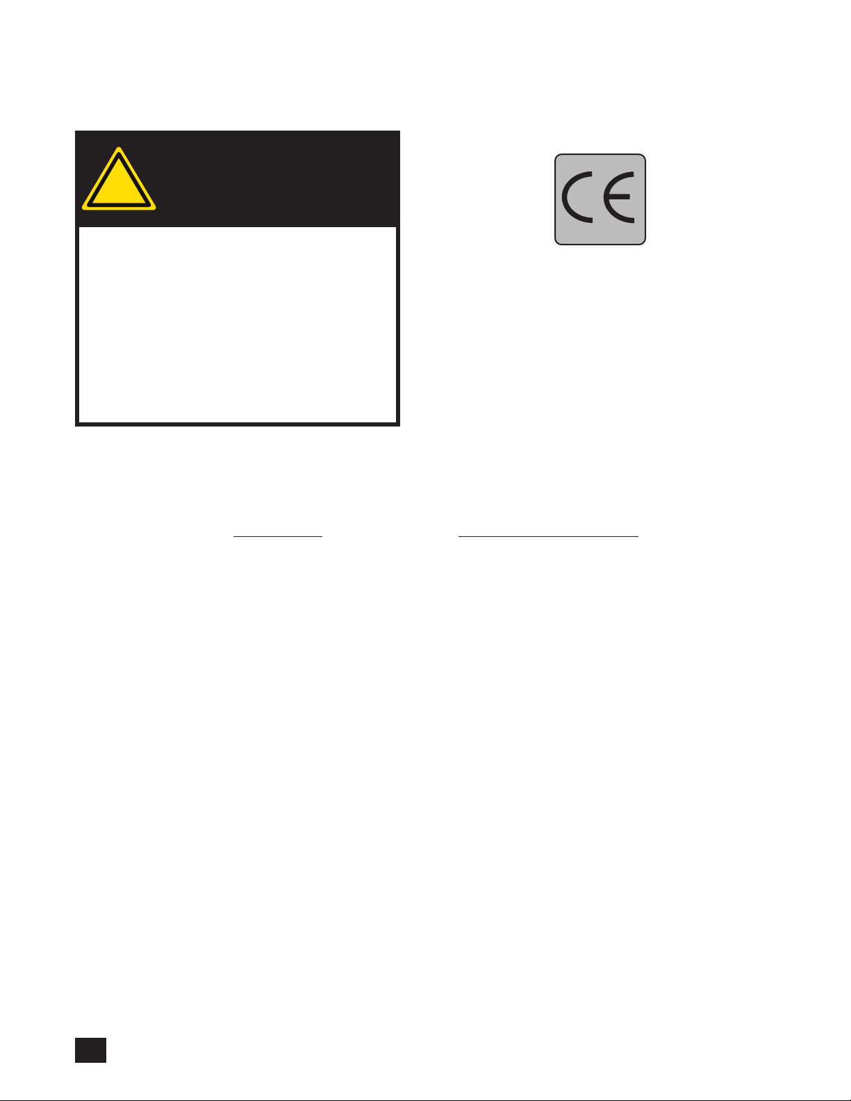
WARNING
is lift fullls requirements
according to
EMC 95/54/EC, 2004/108/EC.
The indicated maximum load rating is appropriate for lifts installed
according to Bruno instructions.
LIFT MODEL MAXIMUM LOAD RATING
VSL-6000 up to 250 lb (113 kg)*
*400 lb (181 kg) w/optional equipment
VSL-6900 up to 400 lb (181 kg)
VSL-6000/6900UK Operator’s 04/16/201
6
©BRUNO
Page 7
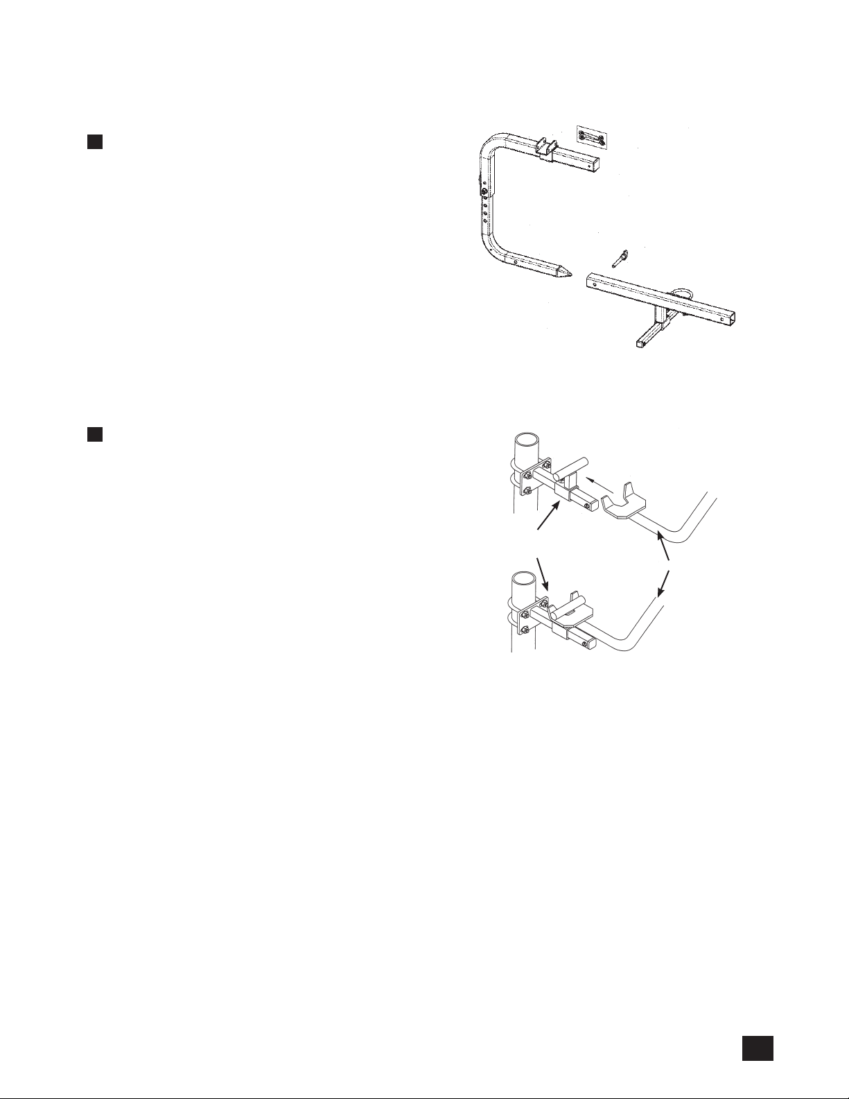
4.0 DOCKING DEVICES
EXAMPLE 4.1
Spinal fusion C-arm and docking device
EXAMPLE 4.2
C-arm and docking device
docking device
C-arm
©BRUNO
VSL-6000/6900UK Operator’s 04/16/2019
7
Page 8
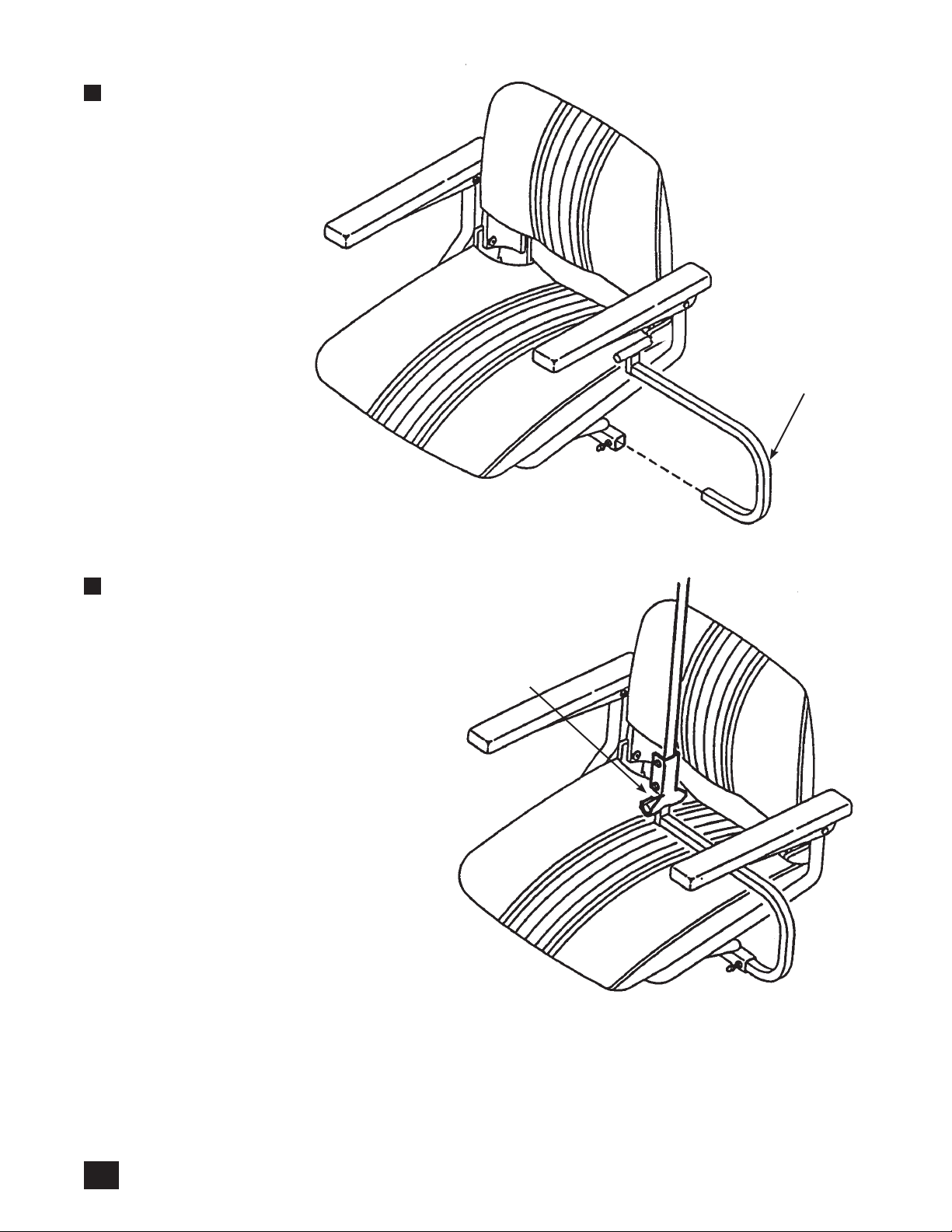
EXAMPLE 4.3
docking device
EXAMPLE 4.4
pickup claw
VSL-6000/6900UK Operator’s 04/16/201
8
©BRUNO
Page 9

5.0 LOADING A MOBILITY DEVICE
STEP 5.1
NOTE: Before loading a mobility device onto the
Curb-Sider, be sure required docking device
has been mounted to the mobility device.
• Park the scooter alongside the vehicle:
- as close to the rear of the vehicle as possible;
- with the scooter facing in the direction opposite that of the vehicle;
- so that the scooter’s front wheel is even with
the vehicle’s rear bumper.
• Open the vehicle’s rear door.
• Check for sucient space behind your vehicle.
Four (4) feet (1.2 m) of clear space behind
the vehicle is usually adequate.
• Move any obstacles that could interfere with
the movement of the scooter as the lift swings
it into the vehicle. Open driver-side door.
• Move mobility device into transfer position.
• Turn scooter o (lock the wheelchair wheels).
!
WARNING
TIP OVER RISK
Allowing mobility
device wheels to roll o
a raised surface during
loading can result in
operator injury and/or
damage to the mobility
device or vehicle.
Keep mobility device
at a safe distance from
raised surfaces (eg.
sidewalk).
©BRUNO
VSL-6000/6900UK Operator’s 04/16/2019
9
Page 10

STEP 5.2
• Locate the control pendant.
• Be sure the pendant is not tangled in the lift
mechanism.
• Depress and hold the UP switch on the control
pendant to raise the C-arm/pickup claw high
enough to avoid catching on something as the
lift swings out of the vehicle.
• Release the button.
• Depress the OUT switch on the control pendant
to swing the lift arm out of the vehicle.
NOTE: Hold the C-arm/pick-up claw as the lift is
powered out to prevent the pick-up device
from swinging freely and contacting the
side of the vehicle.
• Release the switch when the lift arm is over the
mobility device.
NOTE: Releasing a pendant switch stops lift
operation.
STEP 5.3
• With the lift positioned over the mobility device, depress and hold the DOWN switch on the
control pendant.
• Guide the C-arm/pickup claw to a position slightly below the docking device (installed on the
mobility device by your dealer).
• Hook the C-arm/pickup claw onto the docking
device as shown at the front of this manual.
• Depress and hold the UP switch on the control
pendant to lift the mobility device. N
NOTE: It may be necessary to raise the
scooter until the C-arm/pickup claw is
approximately 1” (25 mm) below the belt
guide.
• Release the switch before the white stitching on
the belt reaches the belt guide.
belt guide.
Stop before stitch
line gets to belt
guide.
10
VSL-6000/6900UK Operator’s 04/16/201
©BRUNO
Page 11

STEP 5.4
• Depress and hold the pendant IN switch to
swing the mobility device into the vehicle
NOTE: Guide the mobility device with your hand
as it swings into the vehicle. Apply gentle
pressure on the mobility device body or
seat.
• Release the IN switch when the scooter is
suspended over the desired location.
• Depress and hold the DOWN switch on the
control pendant.
• Release the switch when the scooter comes to
rest on the vehicle oor.
• Be sure that:
- the scooter rests rmly on as level an area as
possible;
- the C-arm/pickup claw remains attached to
the mobility device, and
- the lift belt remains taut.
STEP 5.5
• SET THE MOBILITY DEVICE’S PARKING
BRAKE and turn o the unit.
• Place the control pendant and its cord in a
secure location in the vehicle.
NOTE: Make suret the pendant is placed where
nothing will come to rest on the buttons.
• Check that no obstacles stand in the way of
closing the vehicle door.
• Close the vehicle door.
©BRUNO
VSL-6000/6900UK Operator’s 04/16/2019
11
Page 12

6.0 UNLOADING A MOBILITY DEVICE
STEP 6.1
• Park the vehicle in a location allowing ample
room to unload the mobility device.
• Open the vehicle door.
• Check for sucient space behind your vehicle.
Four (4) feet (1.2 m) of clear space behind the
vehicle is usually adequate.
• Be sure there are no obstacles that could interfere with the movement of the mobility device
as the lift swings it into the vehicle.
• Locate the control pendant.
• Be sure the pendant is not tangled in the lift
mechanism.
• Position yourself out of the exit path of the lift
as it swings out of the vehicle.
STEP 6.2
NOTE: Releasing a pendant switch stops lift
operation.
• Depress and hold the UP button on the control
pendant to lift the mobility device from the
vehicle oor.
• When the scooter is at a height where it will
not catch on anything, release the UP button to
stop lift operation.
• Depress and hold the OUT button on the control
pendant to swing the scooter out of the vehicle.
NOTE: Be sure to guide the mobility device with
your hand.
• When scooter is suspended over the desired location,
release the OUT button to stop lift operation.
• Depress and hold the DOWN button on the
control pendant to lower the mobility device to
the ground.
• Release the DOWN button once the mobility
device reaches the ground, and after a sucient
amount of slack exists in the belt to allow you
to unhook the C-arm from the docking device.
To transfer the mobility device
from the vehicle onto a
sidewalk, park the vehicle so
that its wheels are within
approximately two 2" (5 cm)
of the curb.
During loading and unloading,
always guide the mobility
device by appying gentle pres-
sure with your hand. This will
keep the mobility device from
rotating while suspended, and
possibly damaging the vehicle.
12
VSL-6000/6900UK Operator’s 04/16/201
©BRUNO
Page 13

STEP 6.3
• Unhook the C-arm/pick-up claw from the
docking device.
• Depress and hold the UP button on the control
pendant to raise the C-arm/pick-up claw to the
belt guide.
NOTE: Stop lift operation before the white stitch-
ing on the lift belt enters the belt guide slot
(see bottom left).
• Depress and hold the IN button on the control
pendant to swing the lift back into the vehicle.
• Release the IN button when the lift is in the
proper location.
• Place the control pendant in a secure location
inside the vehicle.
Is the cord completely inside the vehicle?
Unload the mobility device onto a
level surface.
If unloading onto a sidewalk with a
curb or onto a raised surface, make
sure all wheels of the mobility device
come to rest on the same plane.
• Close the vehicle door.
stop before
white stitching
reaches belt guide
©BRUNO
VSL-6000/6900UK Operator’s 04/16/2019
13
Page 14

7.0 VSL-6900: SPECIAL OPERATING INSTRUCTIONS
STEP 7.1
e VSL-6900 features a telescoping lift head that
extends up to 8" (20 cm) and is able to lift a mobility
device weighing up to 400 lb (181 kg) into a vehicle
whose door/hatch opening is narrow.
• Lift up the lift arm.
• Depress and hold the OUT button on control
pendant to rotate the lift arm out of the vehicle.
• Release the OUT button when the lift arm is
perpendicular to the vehicle rear bumper.
• Depress and hold the EXTEND button on the
control pendant.
• Release the EXTEND button when lift arm,
when rotated further, will not contact vehicle.
• Depress the OUT button to continue rotating
the lift.
• Release the OUT button when lift is in correct
position over scooter or wheelchair to be lifted.
STEP 7.2
• Depress and hold the DOWN button on the
control pendant to lower the pick-up device.
• Release the DOWN button when the pick-up
device is slightly below the docking device.
• Attach the pick-up device to the docking device.
• Depress and hold the UP button on control pendant.
• Release the UP button when the mobility device
reaches a height where it will clear the vehicle
rear bumper/tailgate.
• Depress and hold the IN button on the control
pendant to rotate the mobility device to the
rear opening of the vehicle.
• Release the IN button when the mobility device
reaches the proper position for loading into the
vehicle.
14
VSL-6000/6900UK Operator’s 04/16/201
©BRUNO
Page 15

STEP 7.3
• Depress and hold the RETRACT button on the
control pendant while guiding the mobility
device with your hand.
• Release the RETRACT button when the mobility
device is over the desired location.
• Depress and hold the IN button to rotate the
mobility device into the vehicle, while guiding the
mobility device with your hand.
• Release the IN button when the mobility device
is over the desired position.
• Depress and hold the DOWN button to lower
the mobility device to the vehicle oor.
• Release the DOWN button when the mobility
device comes to rest on the vehicle oor.
STEP 7.4
• Be sure that:
- the mobility device rests rmly on as level an
area as possible;
- the pick-up device remains attached to the
mobility device, and
- the lift belt remains taut.
• SET THE MOBILITY DEVICE’S PARKING
BRAKE and turn o the unit.
• Place the control pendant and its cord in a secure location in the vehicle.
NOTE: Make sure the pendant is placed where
nothing will come to rest on the buttons.
• Check that no obstacles stand in the way of
closing the vehicle rear door or tailgate.
• Close the vehicle rear door or tailgate.
©BRUNO
VSL-6000/6900UK Operator’s 04/16/2019
15
Page 16

8.0 OPTIONAL FOLD-DOWN QUICK RELEASE PIN KIT
STEP 8.1
For those customers wishing to have the added capability of folding down the lift head, Bruno oers
an optional fold-down quick release pin kit.
• Remove the nut on the 1/2" bolt.
• As you hold the head at the end of the arm
(near the belt), remove the 1/2" bolt. You may
discard the bolt.
remove
1/2” bolt
Support head here
while removing bolt
and inserting pin.
16
VSL-6000/6900UK Operator’s 04/16/201
©BRUNO
Page 17

STEP 8.2
• In the 1/2" bolt hole, insert the larger of the
quick release pins.
• Insert the smaller quick release pin as shown to
the right.
STEP 8.3
To fold down the lift head:
• Remove the smaller quick release pin.
Insert the smaller
quick release pin
here for folded up
position.
Insert the
smaller quick
release pin here
for folded down
position.
Replace this bolt
with the larger
quick release pin.
• While holding the lift arm (near the belt end),
remove the larger quick release pin.
• Fold down the head.
• Insert the smaller quick release pin in the hole
shown to the left.
• Reinsert the larger quick release pin in the same
hole from which it was removed.
larger
pin
smaller
pin
©BRUNO
VSL-6000/6900UK Operator’s 04/16/2019
17
Page 18

9.0 EMERGENCY BACKUP OPERATION
STEP 9.1
e Curb-Sider is equipped with a hand crank to
serve in case of a power failure.
NOTE: is hand crank is intended solely to
maneuver the lift back into the vehicle so
that the vehicle may be driven.
Accessing and using the hand crank:
• Remove the four (4) thumb screws securing the
cover to the lift base.
• Compress the boot with your hands to tuck it
inside the cover (see right).
Loosen (4)
cover screws.
18
VSL-6000/6900UK Operator’s 04/16/201
©BRUNO
Page 19

STEP 9.2
• Slide the cover up, rotating the cover
approximately 90 degrees to provide access to
the base motor.
NOTE: Hold the cover up and out of your way as
you locate the emergency crank.
• Once the cover is raised over the motor, you may
wish to rotate it 90 degrees and tuck it behind the
motor.
• Locate the emergency crank.
STEP 9.3
• Place the emergency crank over the motor shaft
as shown.
• Rotate the crank until the lift has returned to
its home position.
• Remove the crank from the motor and store it
in the vehicle glove box.
• Have the lift examined by an authorized Bruno
dealer.
emergency crank
©BRUNO
VSL-6000/6900UK Operator’s 04/16/2019
19
Page 20

10.0 MAINTENANCE AND TROUBLESHOOTING
Take the vehicle and lift to an authorized Bruno dealer for complete inspection and any necessary repairs/
replacements once a year (every 6 monts if the lift is used under strenuous conditions).
Recommended maintenance operations:
• inspect the lift belt • clean and grease chains • check electrical system
• check and adjust docking device
PROBLEM POSSIBLE CAUSE / SOLUTION
Lift does not operate Verify that circuit breaker is ON.
Lift belt goes down when UP pendant switch is
pressed, and up when DOWN switch is pressed
Lift makes grinding noise Have the unit inspected by an authorized Bruno
Lift has been run down too far and belt has wrapped.
backwards around spool. Run lift down until belt
wraps correctly onto the spool.
dealer.
20
VSL-6000/6900UK Operator’s 04/16/201
©BRUNO
Page 21

Page 22

Page 23

Page 24

6000/6900-UK-O
 Loading...