

Page 1
Safety
Operating and installation instructions
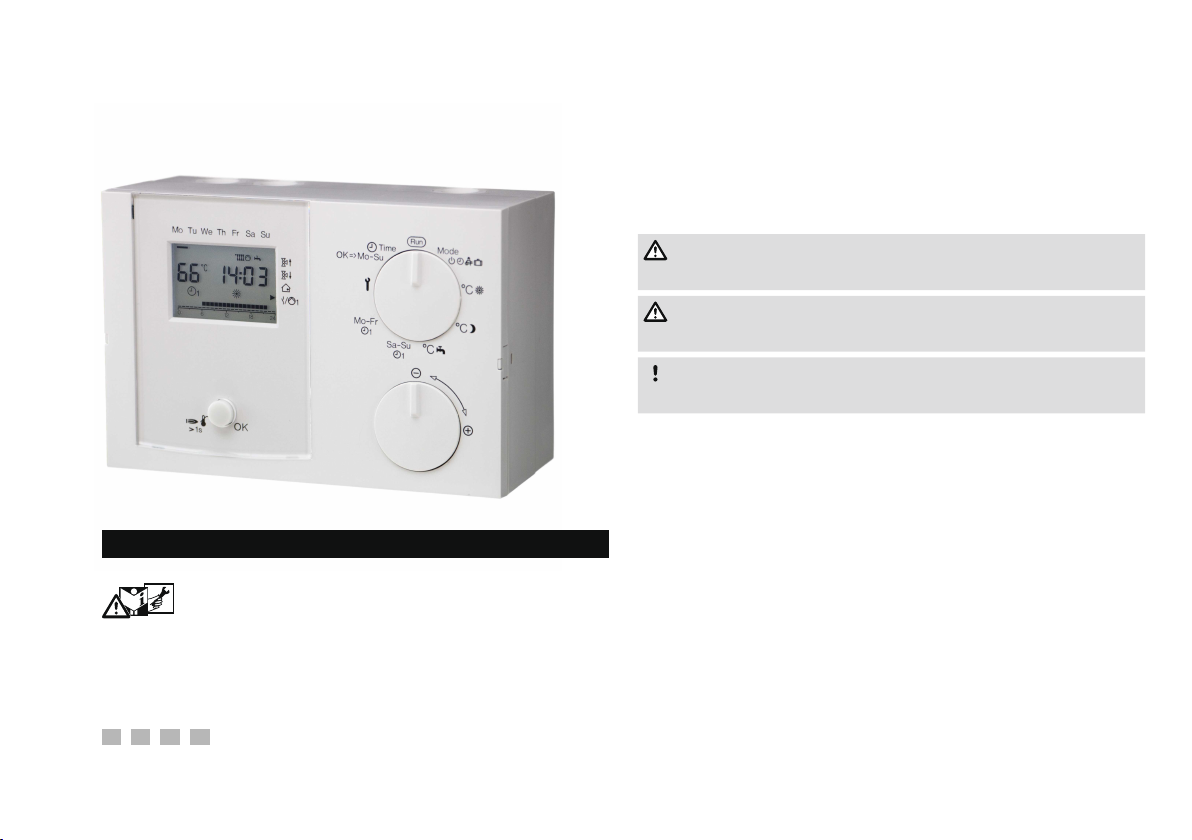
Heating Controller Lago 01
Liability
We will not be held liable for damages resulting from non-observance
of the instructions and non-compliant use.
Safety instructions
Information that is relevant for safety is indicated in the instructions
as follows:
DANGER
Indicates potentially fatal situations.
WARNING
Indicates possible danger to life and limb.
Safety
Please read and keep in a safe place
Please read through these instructions carefully before
installing or operating. Following the installation, pass the instructions on to the operator.
These instructions can also be found at www.docuthek.com.
Explanation of symbols
• , 1 , , ... = Action
▷ = Instruction
CAUTION
Indicates possible material damage.
All work and settings in the chapters “Expert” may only be carried
out by a qualified technician. Electrical interventions may only be
carried out by a qualified electrician. The heating system must be
disconnected from the power supply before any electrical work is
carried out on the unit.
Conversion
All technical changes are prohibited.
Transport
On receipt of the product, check that the delivery is complete. Report
any transport damage immediately.
Storage
Store the product in a dry place. Ambient temperature: see Technical data.
Page 2
Table of contents
Table of contents
Heating Controller Lago 01 .........................1
Safety.............................................1
Table of contents ...................................
Verify type of application............................. 6
Type designation codes ...............................6
Part designations ....................................6
Selector switch ...........................................6
Display .................................................7
User – Settings .....................................8
Set time and day of the week...........................8
Set the desired temperature............................ 8
Desired room temperature Day . . . . . . . . . . . . . . . . . . . . . . . . . . . . . . .8
Setback temperature (desired room temperature Night) ............8
Desired hot water temperature ...............................8
Display actual temperatures ............................8
Set operating mode ..................................8
Standby/OFF ..........................................9
1 Automatic mode 1 .....................................9
2 Automatic mode 2 .....................................9
Day mode ............................................9
Night mode (reduced night mode) ..........................10
Summer mode ........................................10
Service ..............................................10
HO Holiday ..........................................10
Set heating program 1 ...............................11
Set heating program 2 ...............................11
Load factory settings (Reset) ..........................12
User – Set parameters ..............................1
List of parameters P01 to P19...............................13
Explanation of the parameters .........................14
P01 – P07 Heating program 2 (Monday to Sunday) ...............14
P08 Operating mode direct heating circuit (HC1)/
P13Operating mode mixer circuit (HC2) .......................14
P09 Heat slope direct heating circuit/
P14Heat slope mixer circuit ................................14
P10 Room sensor influence direct heating circuit/
P15 Room sensor influence mixer circuit.......................15
P11 Room sensor correction direct heating circuit/
P16 Room sensor correction mixer circuit ......................15
P18 Hot water according to program .........................15
P19 Indication of heating program at the lower margin of the display .16
User – Questions ..................................16
How do I switch to summer/winter time? .................16
How do I set the heating controller so that it gets warm
sooner in the morning? ..............................16
My heater does not get warm enough. What can I do? ......16
How do I set the heating system for holidays? .............17
How can I switch the heating system off during the summer? . 17
Is it possible to let the heating system run longer in the
evening for special occasions such as a party? ............17
How do I set the heating controller to save energy? .........17
Which room is allocated to which heating circuit? ..........17
My heating system is not running .......................17
2
Page 3

Table of contents
Expert - Installation ................................18
Expert - Electrical connections ......................18
Define application...................................18
Connection diagram controller without socket .............21
Connection diagram controller with socket................22
Options ..........................................23
Maximum limiter .........................................23
Examples of installations .............................24
Heating system controller for heat source, mixed heating circuit and
hot water preparation .....................................24
Heating system controller for mixed heating circuit and hot water
preparation from a buffer storage tank.........................25
Heating system controller for direct heating circuit, mixed heating
circuit and hot water preparation .............................26
Controller for a mixed heating circuit as expansion for a heating
system controller .........................................27
Controller for a heat source in a cascade: Heating module .........28
Internal hot water preparation of the first heat source in the cascade
(hydraulic separation)......................................30
Expert – Set DIP switches ...........................1
Direct heating circuit or multifunction relay......................31
Assigning a remote control FBR2 to the direct heating circuit or
mixer circuit.............................................31
Set sensor resistance .....................................31
Expert – Set parameters ............................
List of parameters P20 to P99 .........................33
Explanation of the parameters .........................34
P20 Code no. input .......................................34
P21 code no. change .....................................34
P22 Outside temperature frost protection ......................34
P23 CAN bus ID mixer circuit (heating circuit address) ............34
P30 Maximum heat source temperature .......................34
P31 Heat source minimum temperature .......................34
P32 Warm-Up Temp .....................................34
P33 Minimum limit heat source . . . . . . . . . . . . . . . . . . . . . . . . . . . . . .34
P34 Dynamic switching hysteresis ...........................35
P35 Hysteresis time ......................................35
P36 Burner starts ........................................35
P37 Burner operating time . . . . . . . . . . . . . . . . . . . . . . . . . . . . . . . . .35
P38 Address heating module (only for cascade operation) .........35
P50 DHW Relief (charging pump lock) ........................35
P51 Parallel pump operation ...............................35
P52 Antilegion function ....................................36
P53 Temperature increase during hot water preparation ..........36
P60 Maximum flow temperature direct heating circuit ............36
P61 Minimum flow temperature direct heating circuit .............36
P69 Additional mixer functions (P77 – 79) ......................36
P70 Maximum flow temperature mixer circuit ...................36
P71 Minimum flow temperature mixer circuit ...................36
P72 Mixer Dynamic OPEN (when opening)/
P73 Mixer Dynamic CLOSED (when closing) ....................36
74 T-Flow Cooling (flow temperature Cooling) ...................37
P75 T-Room Cooling (desired room temperature) ................37
P76 Min TO Cooling (Minimum outside temperature for cooling) .....37
P77 Mixer scan time ......................................38
P78 Mixer operating time limit ..............................38
P79 Mixer start seconds ...................................39
P80 MF Relay function ....................................39
P81 Switching temperature of the multifunction relay .............40
P82 Multifunction relay hysteresis ............................40
P97 PC enable (0000 = disabled) ............................40
P98 Relay Test ..........................................40
P99 Software version and index (63.XX) .......................40
Expert – Checklist for commissioning .................41
3
Page 4
Table of contents
Service...........................................4
STL Test .........................................42
Accessories ......................................4
Operating module Merlin BM, BM8, or remote control Lago
FB ..............................................43
Merlin BM ..............................................43
Lago FB ...............................................43
PC Adapter .......................................43
CoCo PC active..........................................44
CoCo PC mobile .........................................44
Remote control and room sensor FBR2 ................44
Room sensor RFB
Outside sensor AF/AFS .................................45
Boiler sensor KF/KFS
Storage sensor SPF/SPFS ...............................45
Flow sensor VF/VFAS
Sensor values ...........................................46
................................44
....................................45
Help with faults....................................47
Technical data ....................................49
Glossary .........................................50
Flow and return flow temperature.......................50
Desired and actual temperature ........................50
Setback temperature ................................50
Heat source .......................................50
Circulation pump ...................................50
Direct heating circuit.................................50
Mixed heating circuit / Mixer circuit .....................50
Heating time.......................................50
Header pump...................................... 51
Feed pump .......................................51
Legionella.........................................51
4
Page 5

Certification ......................................51
Declaration of conformity .............................51
Eurasian Customs Union .............................51
Heating circuit allocation ...........................5
For the installation expert .............................52
Contact ..........................................5
Table of contents
5
Page 6
Verify type of application
Verify type of application
Heating controller to be used as a
– heating system controller,
– mixer extension or
– as a controller for a heat source in a cascade,
for further explanation see page 18 (Expert - Electrical connections).
The heating controller regulates two independent heating circuits:
one indirect heating circuit and one mixer circuit.
The function is only guaranteed within the specified limits, see page
49 (Technical data).
Any other use will be deemed improper use.
Type designation codes
Code Description
Lago Heating controller
0 On//Off boiler control
Mixer circuit and hot water preparation
Temperature-controlled multifunction relay
1 CAN bus communication
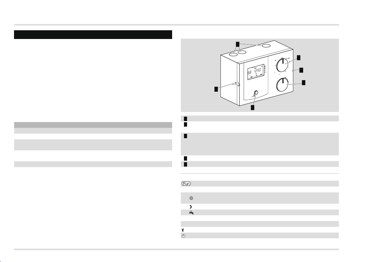
Part designations
5
Mode
Time
OK⇒Mo–Su
Th Fr Sa So
Mo Tu We
1
4
>1s
Mo–Fr
1/
1
Sa–Su
OK
3
1 Selector switch
Rotary knob
for changing the set values and displaying the temperatures
OK button
for displaying the desired temperature of the heat source, for
confirming settings, and the for testing the Safety Temperature
Limiter
4 Assembly holder of the controller
5 Cable feed-throughs
Selector switch
Standard
Mode Operating mode selection
°C
°C
°C
Desired room temperature Day (for both heating
circuits)
Setback temperature (for both heating circuits)
Desired hot water temperature
Sa – Su Heating program 1 from Saturday to Sunday
Mo – Fr Heating program 1 from Monday to Friday
Parameter setting for User and Expert
Time Setting the time and the day of the week
1
°C
°C
4
°C
1
2
6
Page 7
Verify type of application
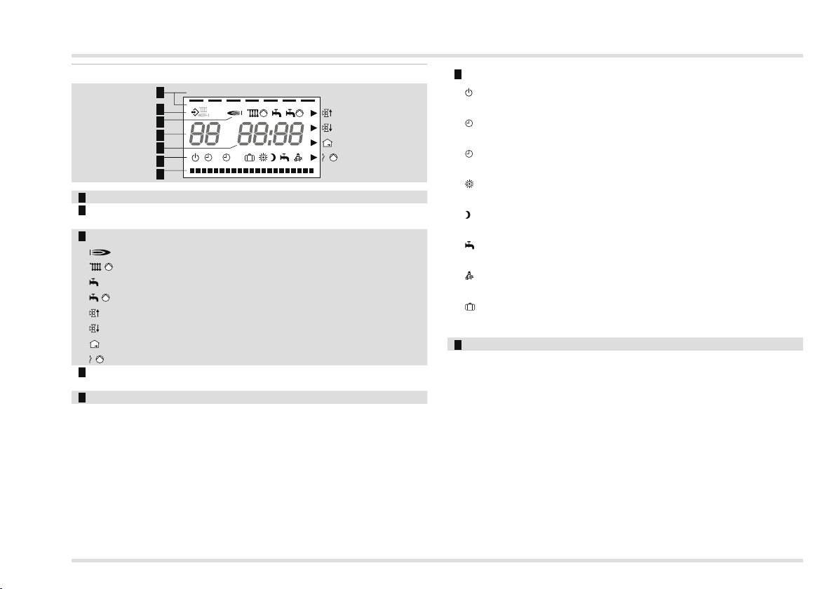
Display
Mo Tu We Th Fr Sa Su
1
2
3
4
5
6
7
1 2
1/
1 Days Monday – Sunday underlined
Communication to devices on the CAN bus (such as Lago FB,
BM8, Merlin BM)
Status indications:
Burner,
Mixer circuit pump,
Hot water enabled,
Storage charging pump,
Mixer open,
Mixer closed,
Room temperature,
/ 1 Multifunction relay /Pump direct heating circuit
4 Heat source temperature (When used as a mixer expansion,
"--" is displayed.)
5 Time
6 Operating modes:
Operational readiness/OFF (Heating and hot water
preparation OFF, frost protection operation only)
1 Automatic mode 1 (Heating according to heating program
1, hot water according to parameter 18)
2 Automatic mode 2 (Heating according to heating program
2, hot water according to parameter 18)
Day mode (24 hour heating with desired room temperature
Day, hot water according to parameter 18)
Night mode (24 hour heating with setback temperature, hot
water according to parameter 18)
Summer mode (Heating OFF, hot water according to
parameter 18)
Service (Heat source controls to maximum heat source
temperature.)
Holiday mode (During holidays the rooms are heated to 15
°C, after the holidays the rooms are automatically heated
according to heating program again.)
7 Display of the heating times
7
Page 8
User – Settings
User – Settings
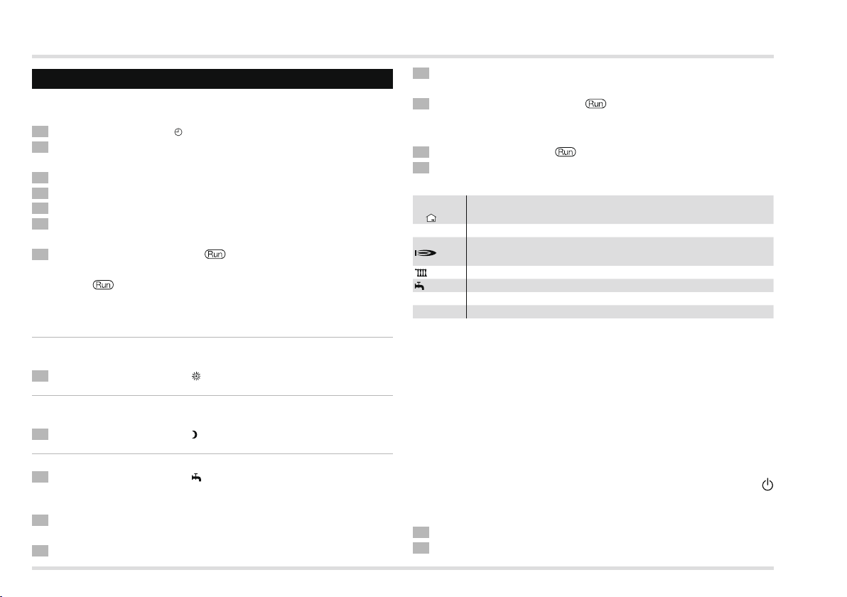
Set time and day of the week
1 Turn selector switch to Time.
Press the OK button.
▷ Display flashes.
Set time with rotary knob.
4 Press the OK button.
5 Set day of the week with rotary knob.
6 Press the OK button.
▷ The new time and the day of the week is displayed.
7 Turn selector switch back to .
▷
To cancel the settings without saving, turn the selector switch
back to at any time.
Set the desired temperature
Desired room temperature Day
▷ Active during heating times
1 Turn selector switch to °C .
Setback temperature (desired room temperature Night)
▷ Active between heating times
1 Turn selector switch to °C
Desired hot water temperature
1 Turn selector switch to °C
All three temperatures
Press the OK button.
▷ Display flashes.
Set day of the desired temperature with rotary knob.
.
.
4 Press the OK button.
▷ The new desired temperature is displayed.
5 Turn selector switch back to .
Display actual temperatures
1 Turn selector switch to .
Use the rotary knob to set one of the following temperature indi-
cations:
H1 to H8
+
AF
*) Hot water temperature
FF *)
* The desired temperature is displayed when the OK button is pressed.
▷ If a sensor is not connected, the display will show -- --.
▷
Room temperature for up to 8 heating circuits
Outside temperature
Heat source and concurrently flow temperature of the
*)
direct heating circuits (1st HC)
*) Flow temperature of the mixer circuit (2ndHC)
Multifunction sensor temperature
The display reverts to the standard indication after a few seconds
without action.
Set operating mode
The operating mode determines how the heating controller works.
Whether the heating system is to be controlled automatically or manually, during a party for example. Or how should the heating system
be controlled during longer periods of absence such as holidays?
The heating controller leaves the factory with the setting
▷
Standby/OFF. The operating mode must be changed for normal
operation.
1 Turn selector switch to “Mode”.
Press the OK button.
8
Page 9
User – Settings
▷ Display flashes.
Set the operating mode using the rotary knob.
4 Press OK after you have selected your setting.
▷ The new operating mode is displayed.
5 Turn selector switch back to .
▷
All operating modes have an effect on the heat source and on
both internal heating circuits of the controller. A different mode
can be assigned to each heating circuit individually, see page 12
(User – Set parameters).
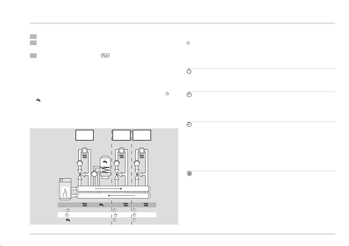
▷ If the controller is used as a heating system controller, all heating
circuits of the system are deactivated for operating modes and
. This only applies to the associated heating circuit when used
as a mixer expansion.
Example: Installation with three mixed heating circuits and
hot water preparation
Lago #1
1
#1
Lago 0321
off off
on on
off
#2
Lago 0321
#2
1
1
off
off
off
#3
Lago 0321
#3
off
1
on
1
offon
1
Lago#1 controls the first heating circuit and hot water. Lago #2
controls the second heating circuit and Lago #3 the third. If mode
was selected for Lago #1, the entire system will be switched off,
regardless of the settings for the other controllers.
You can set the following operating modes
Standby/OFF
Heating and hot water preparation are deactivated. Only the frost
protection function remains active.
1 Automatic mode 1
Heating occurs according to heating program 1: Heating occurs at
identical times for Monday – Friday, as well as Saturday – Sunday. Hot
water according to parameter 18, see page 11 (Set heating program 1).
Automatic mode
Heating occurs according to heating program 2: You can set Individual
heating times for each day. Hot water according to parameter 18,
see page 11 (Set heating program 2).
▷
Toggling between Automatic mode 1 and 2 can be useful for shift
workers. The times do not need to be entered for each shift - they
only need to be switched over.
Day mode
Heating occurs for 24 hours to desired room temperature Day. Hot
water according to parameter 18, see page 8 (Set the desired temperature).
This setting is required for events such as a party, when the heating period in automatic mode will not be sufficient. Do not forget to
switch back to automatic mode once the party is over.
9
Page 10
User – Settings
S
1/
Th Fr Sa So
1/
1
°C
Mode
Time
OK⇒Mo–Su
°C
°C
1
Sa–Su
1
Mo–Fr
°C
Mode
Time
°C
°C
1
Sa–Su
1
Mo–Fr
1/
Th Fr Sa So
1/
1
°C
Mode
Time
OK⇒Mo–Su
°C
°C
1
Sa–Su
1
Mo–Fr
Night mode (reduced night mode)
Heating is reduced to the setback temperature for 24 hours.
Hot water according to parameter 18, see page 15 (P18 Hot water
according to program).
This setting can be used to save energy; in exceptional cases when
no-one is going to be home during the day over a longer period of
time for example. Do not forget to switch back to automatic mode
once the party is over.
Summer mode
The heating system is switched off to save energy. Parameter 18 for
hot water must be set to 1, 2 or 4, see page 12 (User – Set parameters).
Service
The heat source heats to the max. temperature set in parameter
30. As soon as the temperature of 65 °C has been reached, the
consumers regulate to their max. flow temperature for heat removal.
Automatic reset after 15min.
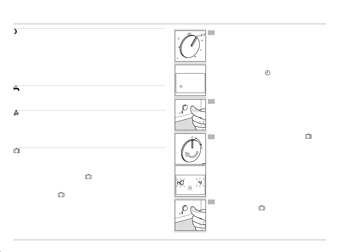
HO Holiday
During holidays the room temperature is regulated to 15 °C.
▷ If parameter 18 is set to 3, hot water preparation is deactivated,
see page 15 (P18 Hot water according to program). If parameter
18 is set to 0, 1, 2 or 4, the HO Holiday mode has no effect
on the hot water preparation.
Example: Setting
You leave on Monday and return Thursday evening. Before leaving
on Monday program:
HO Holiday operating mode
Mode
Time
Mo–Su
Mo–Fr
°C
1
a–Su
Mo Tu We Th Fr Sa So
1
OK
>1s
Mo Tu We Th Fr Sa So
OK
>1s
1 Turn selector switch to „Mode“.
°C
°C
▷ The display shows the current operating mode
(e.g. automatic mode 1)
Press the OK button.
▷ Display flashes.
Rotate the rotary knob clockwise until HO 4
flashes in the display.
▷
HO 4 indicates that 4 absent days have been programmed (in this example Mon, Tue, Wed and
Thu).
4 Press the OK button.
▷ The display shows HO 4.
10
Page 11
User – Settings
°C
Mode
Time
°C
°C
1
Sa–Su
1
Mo–Fr
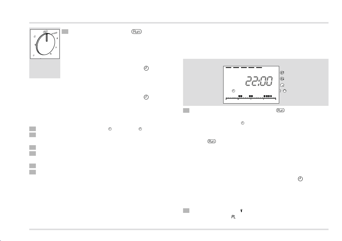
Example: Indication of the heating times for heating
program 1
Heating is to occur from Monday to Friday respectively between 6:00
and 8:00 in the morning, from 11:30 to 13:00 at lunchtime and from
18:00 to 22:00 in the evening.
Mo Tu We Th Fr Sa So
⇒Mo–Su
Mo–Fr
Mode
Time
1
Sa–Su
5 Turn selector switch back to .
▷ The holiday function starts immediately and ends
°C
on Thursday at 24:00. On Friday (day 5) heating
°C
°C
mode reverts to the original mode.
▷
Should you return from your holiday before this
time, you will need to set the original operating
mode again (e.g. automatic mode 1).
Set heating program 1
Heating program 1 is assigned to automatic mode 1. It is used
to define the heating times for the working week (Mo – Fr) and the
weekend (Sa – Su). You can set three heating times per day.
▷ During heating times the controller heats to desired temperature,
between heating times to setback temperature.
1 Rotate selector switch to Mo – Fr 1 or Sa – Su 1.
Press the OK button.
▷ The start time of the first heating time flashes.
Use the rotary knob to select the start time.
4 Press the OK button.
▷ The end of the first heating time flashes.
7 Finally, turn the selector switch back to .
▷
The heating program 1 has been set. In order to apply it, set
the operating mode to “ 1 Automatic Mode 1” , see page 8 (Set
operating mode).
▷
To cancel the process without saving, turn the selector switch
back to at any time.
▷ Factory setting:
Mo – Fr: 6:00 to 22:00
Sa – Su: 7:00 to 23:00
1
0 6 12 18 24
1/
5 Use the rotary knob to select the end time.
6 Press the OK button.
▷ Continue with step 3 to set the second and third heating time.
▷ The heating times will only be saved once you have entered all
three heating times or have set the start time to “----”.
▷
If you want to delete an existing heating time, use the rotary knob
to set the start or end time to “----”.
Set heating program
Heating program 2 is assigned to automatic mode 2. It can be
used to set the heating times for each individual day. You can set
three heating times per day.
▷ During heating times the controller heats to desired temperature,
between heating times to desired temperature Night.
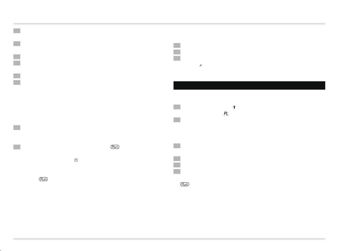
1 Turn selector switch to (Parameter setting).
▷ The display shows .
11
Page 12
User – Set parameters
Turn the rotary knob one step in clockwise direction.
▷ The display shows 01 (Monday).
Press the OK button.
▷ The start time of the first heating time flashes.
4 Use the rotary knob to select the start time.
5 Press the OK button.
▷ The end of the first heating time flashes.
6 Use the rotary knob to select the end time.
7 Press the OK button.
▷ Continue with step 3 to set the second and third heating time.
▷ The heating times will only be saved once you have entered all
three heating times or have set the start time to “----”.
▷
If you want to delete an existing heating time, use the rotary knob
to set the start or end time to “----”.
Example: see page 11 (Set heating program 1).
8 Turn the rotary knob clockwise to the next day: 02 = Tuesday to
07 = Sunday.
▷ Continue with step 3.
9 Finally, turn the selector switch back to .
▷
The heating program 2 has been set. In order to apply it, set
the operating mode to “ 2 Automatic Mode 2”, see page 8 (Set
operating mode).
▷
To cancel the process without saving, turn the selector switch
back to at any time.
▷ Factory setting:
Mo – Fr: 6:00 to 8:00, 16:00 to 22:00
Sa – Su: 7:00 to 23:00
Load factory settings (Reset)
▷ All personal settings will be lost.
1 Take a note of all the settings you have made in these instructions.
Switch off mains.
When switching the mains back on, keep the OK button pressed
until EE P appears in the display.
▷ The factory settings have been loaded.
User – Set parameters
As for heating program 2 you can change further parameters to
adapt the heating system to your requirements.
1 Turn selector switch to (Parameter setting).
▷ The display shows .
Turn the rotary knob clockwise until the parameter you want
to change appears in the left-hand side of the display: 08 to 19
(operating mode direct heating circuit until to display heating
program).
Press the OK button.
▷ Display flashes.
4 Use the rotary knob to set the desired value.
5 Press the OK button to confirm.
6 After you have made the setting, continue with step 2 if you want
to change further parameters, or turn the selector switch back to
.
▷
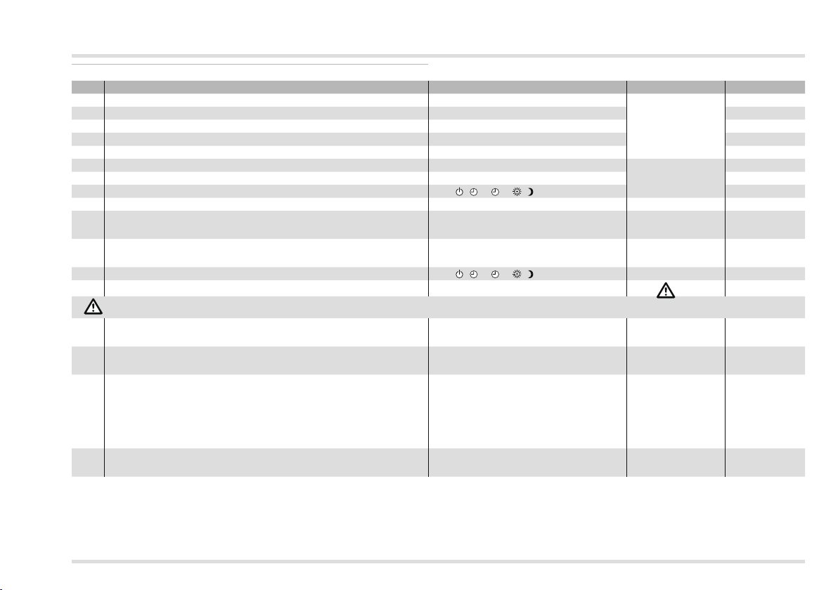
The table – see page 13 (List of parameters P01 to P19) – shows the
possible settings (including the parameters for heating program 2).
▷
The heating controller will only display those parameters for which
there are sensors connected.
12
Page 13
User – Set parameters
List of parameters P01 to P19
P-No.
Parameter Setting range Factory setting Own values
01 Heating program 2 for Monday 00:00 – 24:00
02 Heating program 2 for Tuesday 00:00 – 24:00
03 Heating program 2 for Wednesday 00:00 – 24:00
04 Heating program 2 for Thursday 00:00 – 24:00
05 Heating program 2 for Friday 00:00 – 24:00
06 Heating program 2 for Saturday 00:00 – 24:00
07 Heating program 2 for Sunday 00:00 – 24:00
08 Operating mode direct heating circuit (HC1) ----,
09 Heat slope direct heating circuit 0.20 – 3.00 1,20
Room sensor influence
10
direct heating circuit
Room sensor correction
11
direct heating circuit
13 Operating mode mixer circuit (HC2) ----,
14 Heat slope mixer circuit 0.20 – 3.00
With underfloor heating set parameter 14 < 1, with radiator heating > 1.
Room sensor influence
15
Mixer circuit
Room sensor correction
16
Mixer circuit
18 Hot water according to program
Indication of heating program at the lower margin of the
19
display
, 1, 2, , ----
OFF, 0 – 20 10
-5 to +5 K 0
, 1, 2, , ----
OFF, 0 – 20 10
-5 to +5 K 0
0 = Off
1 = Heating program 1
2 = Heating program 2
3 = 1 hour before heating
4 = 24 hours hot water
0 = for direct heating circuit
1 = for mixed heating circuit
06:00 – 08:00
16:00 – 22:00
07:00 – 23:00
1.20
1
0
13
Page 14

User – Set parameters
Explanation of the parameters
P01 – P07 Heating program (Monday to Sunday)
Heating program 2 is assigned to Automatic mode 2, see page 11
(Set heating program 2).
P08 Operating mode direct heating circuit (HC1)/
P1Operating mode mixer circuit (HC)
P08 = ----: The direct heating circuit operating mode corresponds
to the value in chapter “Set operating mode”.
P13 = ----: The mixer circuit operating mode corresponds to the
value in chapter “Set operating mode”.
A separate and different operating mode can be selected for both
circuits individually.
1 = Standby/OFF
2 = 1 Automatic mode 1
3 = 2 Automatic mode 2
4 = Day mode
5 = Night mode (reduced night mode)
Exception: The general operating modes Standby/OFF and
Summer mode have a reducing effect on the entire system. All
heating circuits are switched off.
Example: Heating by means of radiators and underfloor
heating
In your house you have heaters that supply the direct heating circuit
with water, and underfloor heating that heats the mixer circuit. Because underfloor heating acts slower than a radiator, the underfloor
heating is to be switched on and off beforehand.
Set the general operating mode “
8 (Set operating mode).
1 Automatic mode 1”, see page
In order to use different heating times for the mixer circuit, set parameter 13 to
Now you can use Heating program 1 to set the heating times for
your radiators and Heating program 2 to set different times for the
floor heating, see page 11 (Set heating program 1) and page 11 (Set
heating program 2).
If the floor heating is meant to be switched off, set parameter 13 to
= Standby/OFF.
P09 Heat slope direct heating circuit/
P14Heat slope mixer circuit
Selecting the correct heat slope saves energy because the heat
sources only heat to the point required by the respective outside
temperature.
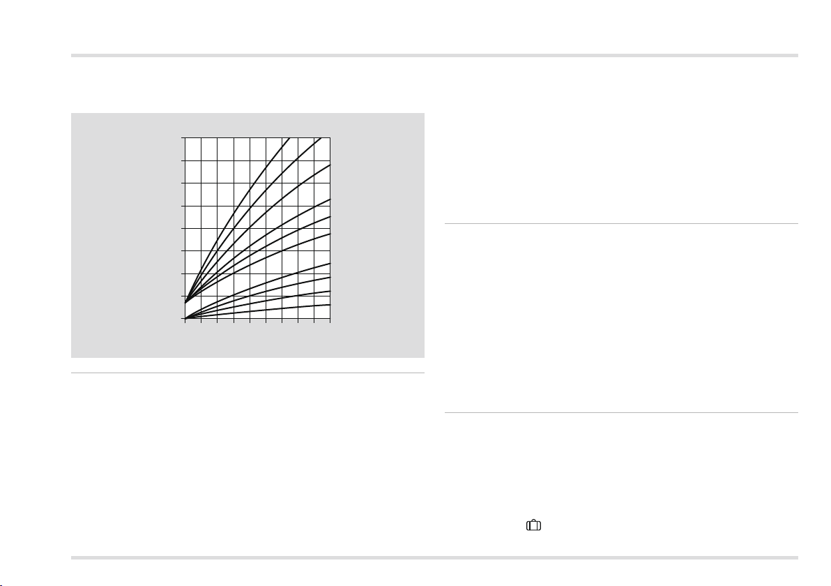
The heat slope specifies the number of °C by which the flow temperature changes when the outside temperature rises or drops.
▷
Before you select the heat slope, set the room temperature to the
desired value, see page 8 (Set the desired temperature).
▷
Ideally, the heat slope is set when the outside temperature is below
5 °C. Changes to the heat slope setting must be applied in small
steps and long intervals (at least 5 – 6 hours between steps). The
system must be allowed to adjust to the new value after each
change to the heat slope.
▷
Select the heat slope so that the desired room temperature is
achieved with the thermostat valves fully opened, and doors and
windows closed.
▷
Increase the heat slope if the desired room temperature is not
reached in combination with low outside temperatures.
▷
If the desired room temperature is not reached in combination with
high outside temperatures, increase the desired room temperature.
• Now change the heat slope.
2 = Automatic mode 2.
14
Page 15
User – Set parameters
3
▷ Typical values:
floor heating: 0.4 to 0.8
Radiators: 1.0 to 1.5
100
80
Flow temperature [°C]
60
40
20
20 16 12 8 4 0 -4 -8 -16 -20
Outside temperature [°C]
2,5
2
1,5
1,2
1
0,8
0,6
0,4
0,2
P10 Room sensor influence direct heating circuit/
P15 Room sensor influence mixer circuit
Only active if a room sensor is connected or an FBR2 remote control
with integrated room sensor is used. It is possible to adjust the influence of the room sensor on the control process.
▷
The higher the set value the greater the influence of the room
sensor on the calculated flow temperature.
P10/15 = OFF: purely weather-guided control
P10/15 = 0: purely weather-guided control
P10/15 = 20: pure room temperature control
Within the range 0 – 20 the heating circuit pump operates up to the
next heating time if there is a heating requirement during the period
of reduced temperature Night (e.g. frost protection of when the
temperature drops below the setback temperature. This prevents
the rooms from becoming too cool.
Example: P10/15 = 5
With this setting the desired temperature of the heat source is increased by 5K when the room temperature drops below the desired
room temperature by 1K.
P11 Room sensor correction direct heating circuit/ P16 Room sensor correction mixer circuit
Only active if a room sensor is connected or an FBR2 remote control
with integrated room sensor is used. This setting can be used to correct measurement errors of the connected room sensor, e.g. when
the room sensor is influenced by incorrect positioning.
Setting range: P11/16 = -5 to +5 K.
Example: Room sensor correction direct heating circuit
Your room sensor measures 20 °C. A reference thermometer, however, determines 22 °C. Now set parameter 11 = 2 so that the value
2 K is added to the measured value.
P18 Hot water according to program
This parameter can be used to define the heating times for hot water.
P18 = 0: Off (no hot water preparation)
P18 = 1: hot water in line with heating program 1
P18 = 2: hot water in line with heating program 2
P18 = 3: 1 hour before the heating times of automatic mode 1 or 2.
(The desired automatic mode is set via the operating mode.
With activated HO Holiday mode the hot water preparation is
not switched on.)
15
Page 16
User – Questions
With the mode “Summer mode” parameter 18 must be set to 1,
2, or 4.
P18 = 4: 24 hours hot water
Example: P18 =
If “Automatic mode 1” was selected as the operating mode, the
heating controller will always switch on the hot water one hour before
switching on the heating. If HO Holiday mode is activated, the
hot water is not switched on.
P19 Indication of heating program at the lower margin of the display
P19 = 0: The heating program for the direct heating circuit is displayed.
P19 = 1: The heating program for the mixed heating circuit is displayed.
User – Questions
How do I switch to summer/winter time?
To switch from summer to winter time and vice verse you need to
reset the time, see page 8 (Set time and day of the week).
How do I set the heating controller so that it gets warm sooner in the morning?
There are two heating programs to set the heating times.
Heating program 1 for setting the heating times Mo – Fr (working
week) and Sa – Su (weekend) for the week as a whole,
Heating program 2 for setting the heating times for each day of the
week Mo, Tu, We, Th, Fr, Sa and Su.
Heating program 1 in operating mode 1 is assigned to automatic
mode 1.
Heating program 2 in operating mode 2 is assigned to automatic
mode 2.
First select automatic mode 1 or 2, see page 8 (Set operating
mode).
Then adjust the associated heating program to suit your needs, see
page 11 (Set heating program 1) or 11 (Set heating program 2).
My heater does not get warm enough. What can I do?
You have two options.
First increase the desired room temperature Day, see page 8 (Set
the desired temperature).
Wait for a few hours to give the heating system time to respond to
the new setting.
16
Page 17

User – Questions
Should the room(s) still not get warm enough, you can increase
the heat slope for the direct heating circuit or the mixer circuit, see page 14 (P09 Heat slope direct heating circuit/
P14Heat slope mixer circuit).
Should this measure not be sufficient, see page 47 (Help with faults)
and contact your heating engineer.
How do I set the heating system for holidays?
If you want to go away for a number of days, you
can set the heating controller to the operating mode
“ HOHoliday”. The heating system will revert to automatic mode at
the end of the holiday so that it will be warm when you come home,
see page 8 (Set operating mode).
How can I switch the heating system off during the summer?
In summer you should set the heating controller to the operating
mode “Summer mode”. This mode deactivates heating and the
system is only used for hot water, see page 8 (Set operating mode).
Is it possible to let the heating system run longer in the evening for special occasions such as a party?
For this purpose select the operating mode “ Day mode”, see page
8 (Set operating mode).
How do I set the heating controller to save energy?
▷
Set the desired room temperature only as high as absolutely
necessary. The energy consumption is increased by around 6%
for every degree, see page 8 (Set the desired temperature).
▷
Set your heating program so that it switches the heating off at
night or at times when no-one is home.
▷ Only open you windows briefly to let in fresh air. Avoid tilted win-
dows over longer periods.
Which room is allocated to which heating circuit?
Please contact your heating engineer to answer this question. You
will find a table on the last page of these instructions where these
allocations can be entered.
My heating system is not running
Check the selector switch position. The selector switch must be
set to .
Check the operating mode. The display must indicate 1 for Automatic
mode 1, or 2 for Automatic mode 2, see page 8 (Set operating mode).
17
Page 18
Expert - Electrical connections
Expert - Installation
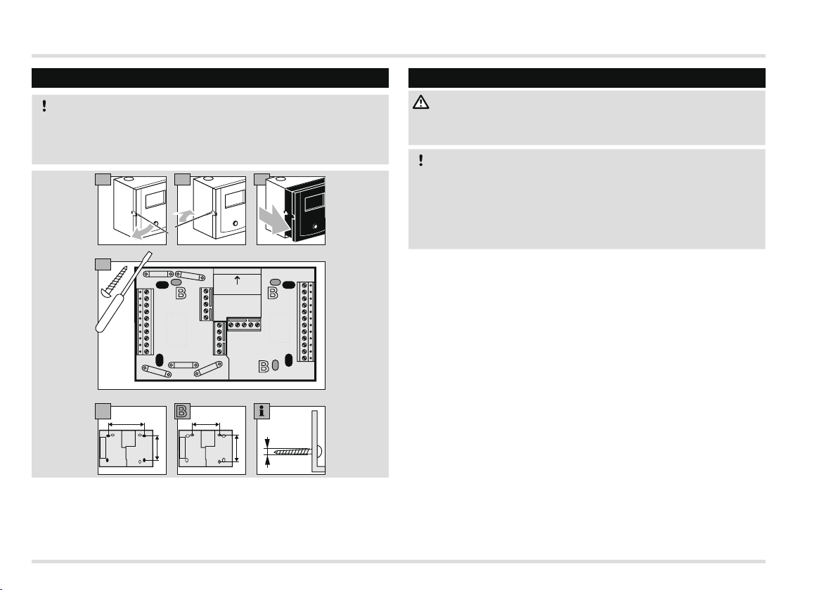
CAUTION
The minimum distance from surrounding heat sources is to be
chosen so that the permitted ambient temperature will not be
exceeded during operation, see page 49 (Technical data).
21a 1b
3
Top
B
A
A
B
A
A
B
A B
95 75
57
Ø 3,5
60
Expert - Electrical connections
WARNING
Possible life-endangering electrical shock! Switch the power off to
electrical cables before working on power-carrying parts!
CAUTION
For fixed devices, an isolating mechanism must be installed for
shutting off from the network, in accordance with the installation
guidelines and EN 60335, e.g. with a switch.
The insulation for line conductors is to protected against damage
by overheating, e.g. insulating sleeve.
Define application
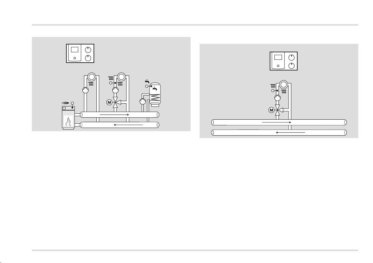
The Lago 0321 can be used for three different applications:
as a heating system controller, as a mixer expansion, or as a controller
for a heat source (boiler control) in a cascade.
The application is determined automatically by connecting certain
sensors and on setting specific parameters.
18
Page 19
Expert - Electrical connections
Heating system controller
Lago 0321
VF
1
KF
SPF
2
Connect heat source sensor (KF/KFS), flow sensor (VF/VFAS) and
storage sensor (SPF/SPFS),
Parameter 38 = “----” (no heating module address)
The following functions are now active:
▷
control of a single-stage heat source or an alternative heat removal
from a buffer storage tank,
▷ control of a hot water preparation system,
▷ control of a mixed heating circuit,
▷
control of a direct heating circuit or, alternatively, an additional
function with multifunction relay, such as a circulation pump, return
flow temperature increase or header pump. (For this purpose,
set the DIP switches and parameters 80 – 82. Additional sensors
may be required.)
Controller for a mixed heating circuit as expansion for a
heating system controller
Lago 0321
VF
This application is automatically activated if only one flow sensor
(VF/VFAS) is connected.
Set parameter 23 to heating circuit address (2 – 15).
The following functions are now active:
▷
Control of an additional mixed heating circuit (expansion for a
heating system controller), e.g. in a multi-family unit.
▷
Control of an additional function with multifunction relay, e.g.
circulation pump or return flow booster. (For this purpose, set
the DIP switches and parameters 80 – 82.)
The following functions can not be used:
▷ Header pump
▷ Heat source pump
19
Page 20
Expert - Electrical connections
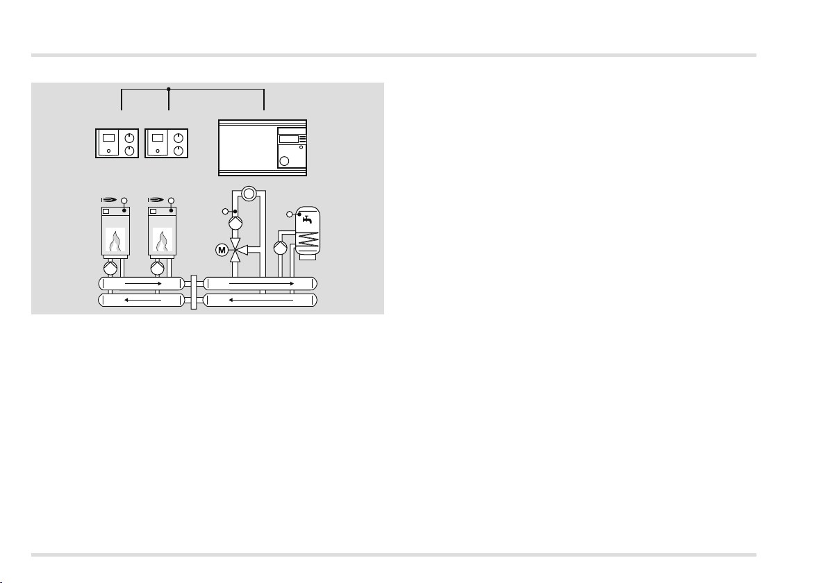
Controller for a heat source in a cascade: Heating module
CAN-Bus
#1
Lago 0321#2Lago 0321
Merlin
KF
KF
VF
SPF
This application is automatically activated as soon as you connect
a heat source sensor (KF/KFS) and set parameter 38 = 1 – 8 (heating module address).
The following functions are now active:
▷ Control of a heat source in a cascade,
▷
Control of an additional function with multifunction relay, e.g. heat
source pump or return flow booster.
▷ A cascade manager, such as Merlin 5064, is required for heating
circuit and hot water control.
20
Page 21
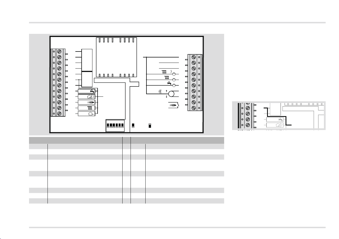
11
N
12
13
14
15
1
2L1
3
4
5
6
7
8
Sensor
230 V
L1’
1/
H
L
–
+
CAN-BUS
1
2
2
M
Connection diagram controller without socket
Sensor
H
11
12
13
14
15
16
17
18
19
20
21
22
L
–
+
1
2
3
SPF
RF
KF
VF 2
AF
CAN-BUS
FBR2
GND
ON
1 2 3 4 5 6
N
= OFF
L1’
= ON
2
T1
T2
Expert - Electrical connections
▷
Use solid lines or flexible lines with wire
end sleeves for connections (230 V).
▷
230 V
1
2L1
3
1/
4
2
5
6
7
M
8
9
10
Route CAN bus lines and sensor lines
separately from power lines.
▷ Never mix 1 kΩ and 5 kΩ sensors.
▷
Only connect sensors required for the
system.
▷
Connect a bridge between terminal 16
and GND bus terminal. If the bridge between terminal 16 and GND is omitted,
the sensor values will not be displayed.
▷ Set bridge and reset heating controller.
2
16
17
18
19
SPF
RF
FBR2
3
GND
SELV, safety extra low voltage
~230 V, switching capacity of the relays 2(2) A, ~250 V
11 – 14 CAN-BUS 1 Neutral conductor mains
15 – 17 FBR2, alternatively: 2 Mains voltage heating controller L1
15 – 16 Room thermostat 3 Mains voltage for the outputs L1‘
16 – 17 Phone switch 4
Pump heating circuit 1 or
multifunction relays
18 Storage sensor 5 Pump heating circuit 2
19
20 Boiler sensor 7 Mixer Open
21 Flow sensor 8 Mixer Close
22 Outdoor sensor 9 – 10 Burner electrically isolated
Room sensor or multifunction sensor
▷ Use solid lines of flexible lines with wire end sleeves for connections (230 V).
▷ Route bus lines and sensor lines separately from power lines.
▷ Never mix 1 kΩ and 5 kΩ sensors.
6 Storage charging pump
21
Page 22
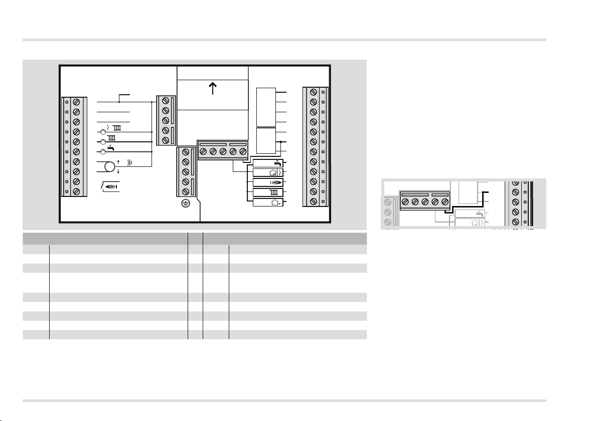
Expert - Electrical connections
Sensor
11
12
13
14
15
H
L
–
+
CAN-BUS
1
Top
Connection diagram controller with socket
SPF
RF
KF
VF
AF
H
L
–
CAN-BUSFBR2
+
1
2
3
Sensor
11
12
13
14
15
16
17
18
19
20
21
2
22
230 V
1
2
3
4
5
N
L1
L1’
1/
2
N
Top
6
7
8
9
10
~230 V, switching capacity of the relays 2(2) A, ~250 V
1 Neutral conductor mains
2
M
GND
T1
T2
SELV, safety extra low voltage
11 – 14
CAN-BUS
2 Mains voltage heating controller L1 15 – 17 FBR2, alternatively:
15 – 16
3 Mains voltage for the outputs L1‘
Pump heating circuit 1 or
4
multifunction relays
Room thermostat
16 – 17 Phone switch
5 Pump heating circuit 2 18 Storage sensor
6 Storage charging pump 19 Room sensor or multifunction sensor
7 Mixer Open 20 Boiler sensor
8 Mixer Close 21 Flow sensor
9 – 10 Burner electrically isolated 22 Outdoor sensor
▷
Use solid lines or flexible lines with wire
end sleeves for connections (230 V).
▷
Route CAN bus lines and sensor lines
separately from power lines.
▷ Never mix 1 kΩ and 5 kΩ sensors.
▷
Only connect sensors required for the
system.
▷
Connect a bridge between terminal 16
and GND bus terminal. If the bridge between terminal 16 and GND is omitted,
the sensor values will not be displayed.
▷ Set bridge and reset heating controller.
2
16
FBR2
3
17
GND
SPF
RF
18
19
22
Page 23
Options
N
1
2
3
230 V
Top
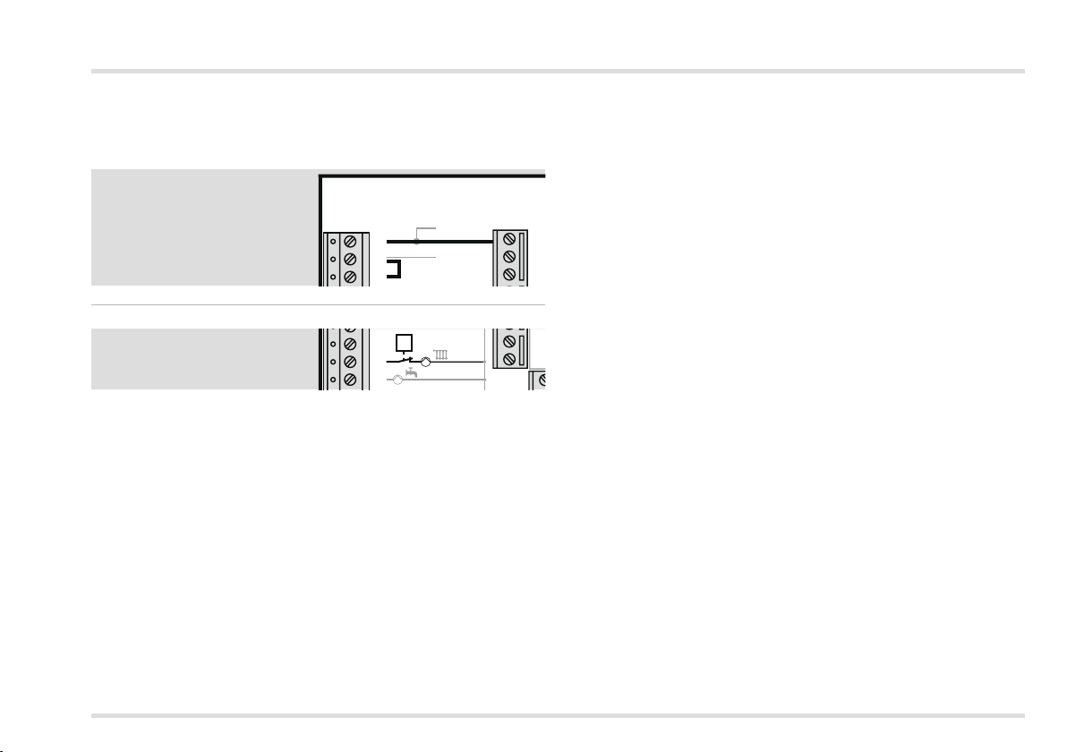
Provided no separate regulations for protecting the relay apply, a
bridge to supply the relay must be connected between terminals
2 and 3.
Expert - Electrical connections
230 V
1
2
3
Maximum limiter
4
5
6
If a maximum limiter is required for the mixed heating circuit, e.g. in
combination with underfloor heating, the limiter must be connected
between terminal 5 and the heating circuit pump.
N
L1
ϑ
2
N
23
Page 24
Expert - Electrical connections
Examples of installations
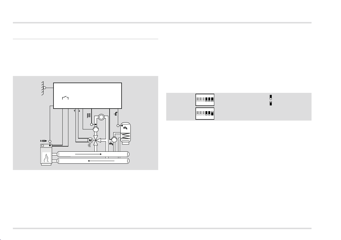
Heating system controller for heat source, mixed heating circuit and hot water preparation
Requirements
In the condition as supplied to the customer the heating controller can
be used for this system, provided the required sensors are connected.
AF
KF
Sensors, see page 4 (Accessories)
▷ AF/AFS external sensor: only with atmospheric control
▷ KF/KFS boiler sensor: in combination with heat source control
▷ VF/VFAS flow sensor: only with mixed heating circuit
▷ SPF/SPFS storage sensor.
22
20
Lago 01
T2T1
867109
21
2
VF
2
185
SPF
▷ FBR2 Remote control with room sensor,
▷ RFB Room sensor on terminals 15+16,
▷ Lago FB, BM8 or Merlin BM operating module, connected via a
CAN-BUS (Terminals 11 – 14).
Set parameters
P14, P18, P19 and P70
The factory settings apply for all other parameters, see page 32
(Expert – Set parameters).
Set DIP switches
ON
1 2 3 4 5 6
ON
1 2 3 4 5 6
KF, SPF, VF, AF… (5 kΩ)
KFS, SPFS, VFAS, AFS… (1 kΩ)
= OFF
= ON
See page 31 (Expert – Set DIP switches) for explanation.
Room control
The room temperature can be detected and controlled as follows:
24
Page 25
Expert - Electrical connections
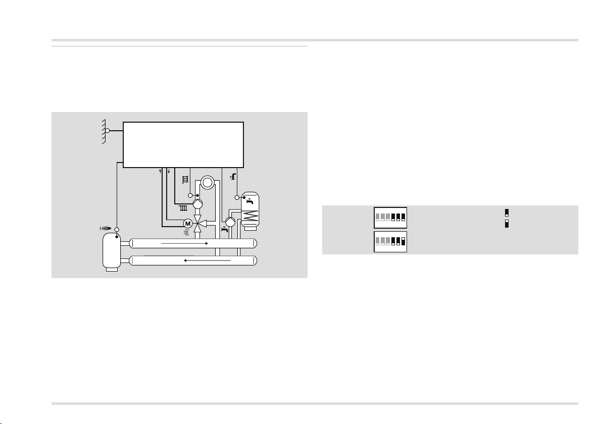
Heating system controller for mixed heating circuit and hot water preparation from a buffer storage tank
Requirements
In the condition as supplied to the customer the controller can be
used for this system, provided the required sensors are connected.
AF
KF
Lago 01
22
20
87 5
21 18
2
VF
2
2
2
6
SPF
Sensors, see page 4 (Accessories)
▷ AF/AFS external sensor: only with atmospheric control
▷
KF/KFS boiler sensor: If the KF/KFS sensor is connected, the
heating circuit pump and the storage charging pump will only
be switched on when the Warm Up Temperature is exceeded at
this sensor. The storage charging pump is only activated when
the heat source temperature (KF/KFS) is also higher than the hot
water temperature (SPF/SPFS).
If no heat source sensor (KF/KFS) is installed, the heating controller
▷
will show “--” for nothing to display.
▷ VF/VFAS flow sensor: only with mixed heating circuit
▷ SPF/SPFS storage sensor
Room control
The room temperature can be detected and controlled as follows:
▷ FBR2 Remote control with room sensor,
Set parameters
P14, P18, P19, P32, P50, P52, P53 and P70
The factory settings apply for all other parameters, see page 32 (Expert
– Set parameters) for explanations.
Set DIP switches
ON
1 2 3 4 5 6
ON
1 2 3 4 5 6
KF, SPF, VF, AF… (5 kΩ)
KFS, SPFS, VFAS, AFS… (1 kΩ)
= OFF
= ON
See page 31 (Expert – Set DIP switches) for explanation.
Additional functions with multifunction relay
The multifunction relay (terminal 4) can be used for additional functions.
▷ DIP switch 4 = “OFF” (Multifunction relay activated)
25
Page 26
Expert - Electrical connections
Circulation pump,
parameters 80
= 02
SPF
Pump heat source
1, P80 = 05
KF
Return flow
booster, P80 = 24
KF
Set P81 and P82
according to boiler
manufacturer’s
specifications
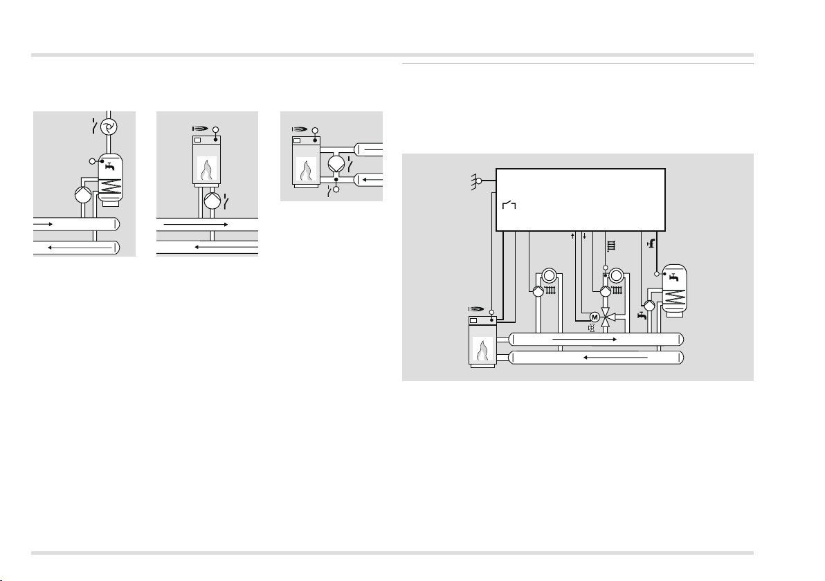
Heating system controller for direct heating circuit, mixed heating circuit and hot water preparation
Requirements
▷ DIP switch 4 = “ON” (direct heating circuit)
▷ Set parameter 23 = Address 2 – 15 for the mixed heating circuit.
KF
AF
22
20
T2T1
4
109
1
Lago 01
587
21 18
2
VF
2
2
6
SPF
Sensors, see page 4 (Accessories)
▷ AF/AFS external sensor: only with atmospheric control
▷ KF/KFS boiler sensor: in combination with heat source control
▷ VF/VFAS flow sensor: only with mixed heating circuit
▷ SPF/SPFS storage sensor
26
Room control
The room temperature can be detected and controlled as follows:
FBR2 remote control with room sensor, Assign the desired heating
▷
circuit using DIP switch 5.
Page 27
Expert - Electrical connections
▷ If a second room sensor is connected to terminal 19, it automati-
cally affects the other heating circuit.
Set parameters
P9, P14, P18, P19, P30, P31, P32, P50, P51, P52, P60 and P70
The factory settings apply for all other parameters, see page 32
(Expert – Set parameters) for explanations.
Set DIP switches
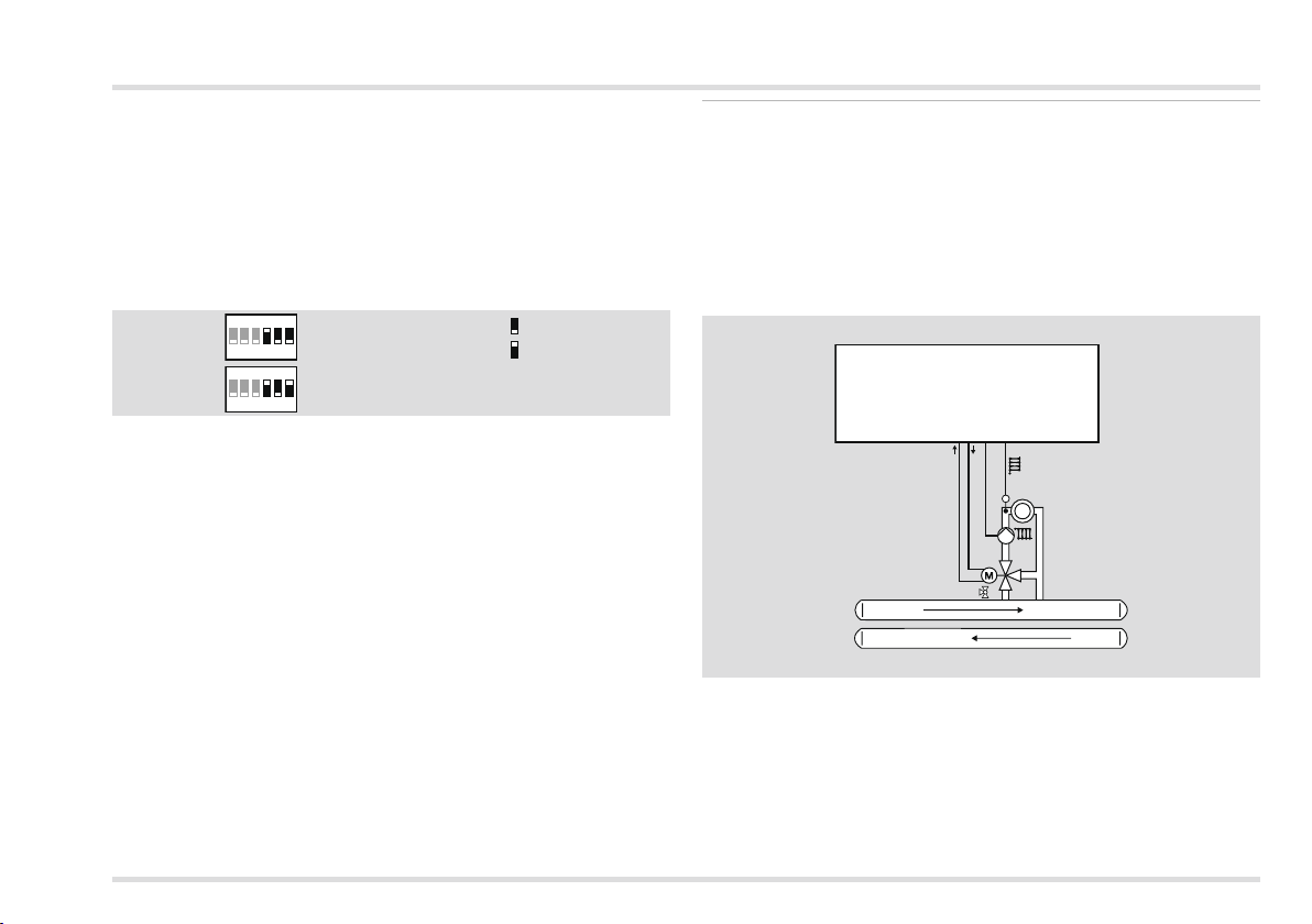
ON
1 2 3 4 5 6
ON
1 2 3 4 5 6
KF, SPF, VF, AF… (5 kΩ)
KFS, SPFS, VFAS, AFS… (1 kΩ)
= OFF
= ON
If a remote control is connected, set DIP switch 5:
▷ DIP switch 5=“ON”: Remote control with room sensor FBR2 for
direct heating circuit,
▷ DIP switch 5=“OFF”: Remote control with room sensor FBR2
for mixer circuit.
See page 31 (Expert – Set DIP switches) for explanation.
Controller for a mixed heating circuit as expansion for a
heating system controller
Requirements
▷ This application is automatically activated if only one flow sensor
(VF/VFAS) is connected.
Set parameter 23 = Address 2 – 15 for the mixer circuit to be
▷
controlled. This address must not be assigned to another heating circuit.
Lago 01
5
87
21
2
VF
2
2
Sensor
▷ VF/VFAS flow sensor: for the mixer circuit.
Set parameters
P14, P19 and P70
The factory settings apply for all other parameters, see page 32 (Expert
– Set parameters) for explanations.
27
Page 28
Expert - Electrical connections
Set DIP switches
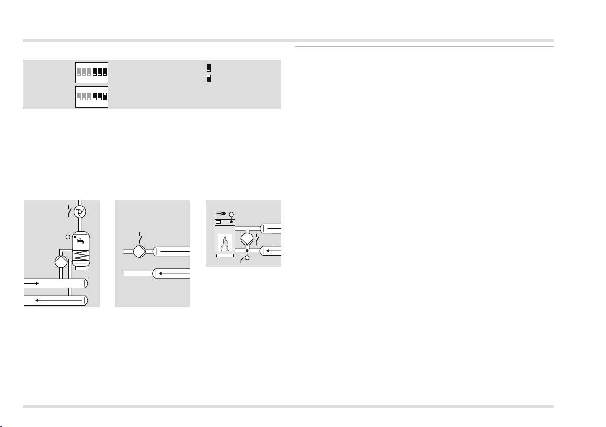
ON
1 2 3 4 5 6
ON
1 2 3 4 5 6
KF, SPF, VF, AF… (5 kΩ)
KFS, SPFS, VFAS, AFS… (1 kΩ)
= OFF
= ON
See page 31 (Expert – Set DIP switches) for explanation.
Additional functions with multifunction relay
The multifunction relay (terminal 4) can be used for additional functions.
▷ DIP switch 4 = “OFF” (Multifunction relay activated)
Circulation pump,
parameters 80
Feed pump 1,
P80 = 03
Return flow
booster, P80 = 24
= 02
KF
SPF
Set P81 and P82
according to boiler
manufacturer's
specifications
Controller for a heat source in a cascade: Heating module
Requirements
This application is automatically activated when
▷ a heat source sensor (KF/KFS) is connected and
▷ parameter 38 is assigned an address 1 to 88 (address heating
module).
The heating controller controls “his” heat source according to the
requests from the cascade controller.
The internal mixer circuit can be used should the mixer circuits con-
trolled by the cascade controller (e.g. Merlin) be insufficient. In this
case, parameter 23 for the internal mixer circuit must be set to an
address 1 – 15.
Sensors, see page 4 (Accessories)
▷ KF/KFS boiler sensor
▷ VF/VFAS Flow sensor (only with use of the internal mixer circuit)
28
Page 29
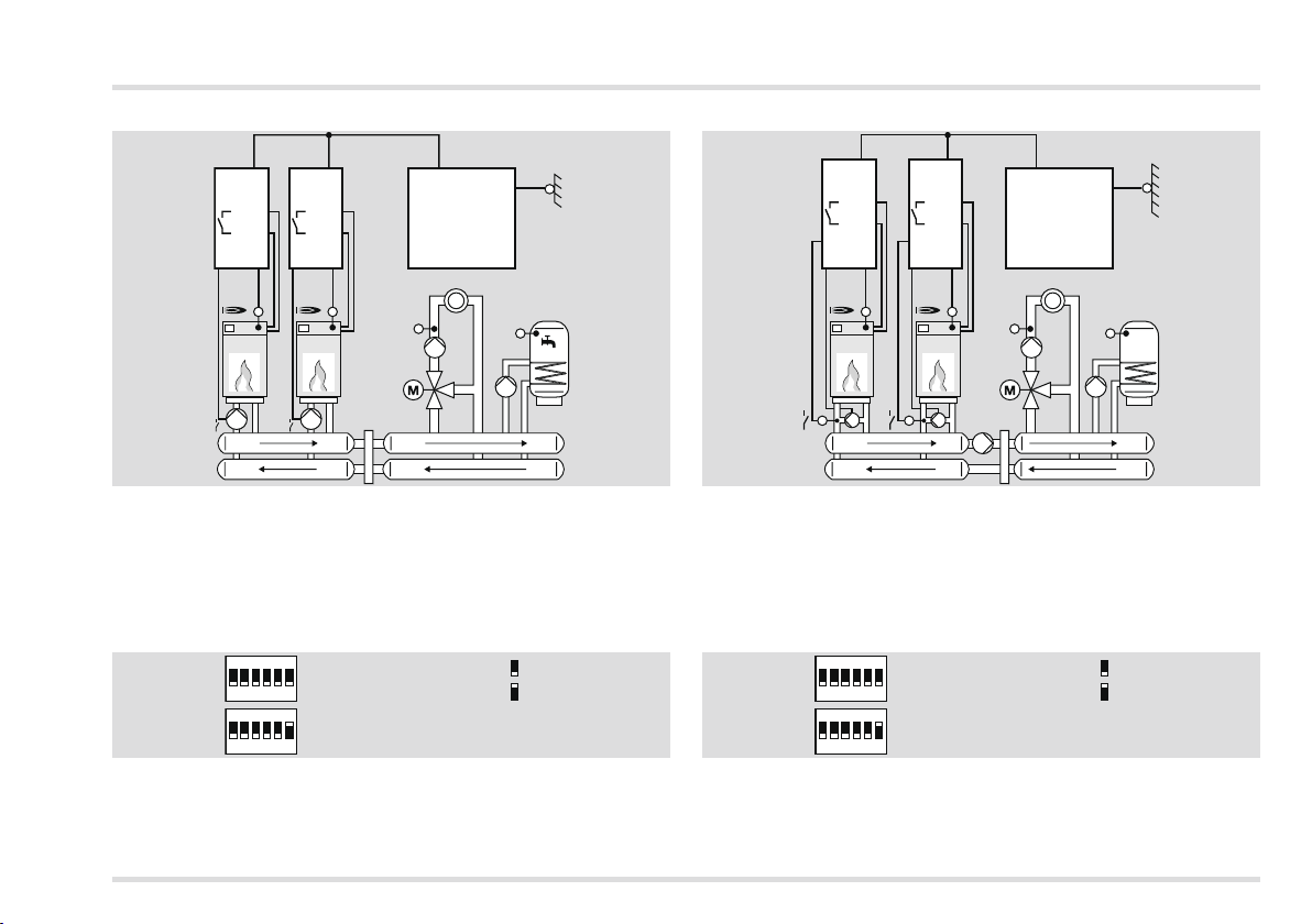
Expert - Electrical connections
The multifunction relay controls the heat source pump.
T2 10
T1 9
CAN-Bus
Merlin
VF
AF
SPF
#1
Lago
0321
T2 10
T1 9
420
KF
#2
Lago
0321
420
KF
Set parameters
P30, P31, P32, P38, P80 = 5
The factory settings apply for all other parameters, see page 32 (Expert
– Set parameters) for explanations.
Set DIP switches
ON
1 2 3 4 5 6
ON
1 2 3 4 5 6
KF, SPF, VF, AF… (5 kΩ)
KFS, SPFS, VFAS, AFS… (1 kΩ)
= OFF
= ON
See page 31 (Expert – Set DIP switches) for explanation.
The multifunction relay controls the return flow booster.
#1
Lago
0321
T2 10
T1 9
41920
KF
#2
Lago
0321
T2 10
T1 9
19
420
KF
CAN-Bus
Merlin
VF
AF
SPF
Set parameters
P30, P31, P32, P38, P80 = 24, P81 and P82
The factory settings apply for all other parameters, see page 32 (Expert
– Set parameters) for explanations.
Set DIP switches
ON
1 2 3 4 5 6
ON
1 2 3 4 5 6
KF, SPF, VF, AF… (5 kΩ)
KFS, SPFS, VFAS, AFS… (1 kΩ)
= OFF
= ON
See page 31 (Expert – Set DIP switches) for explanation.
29
Page 30
Expert - Electrical connections
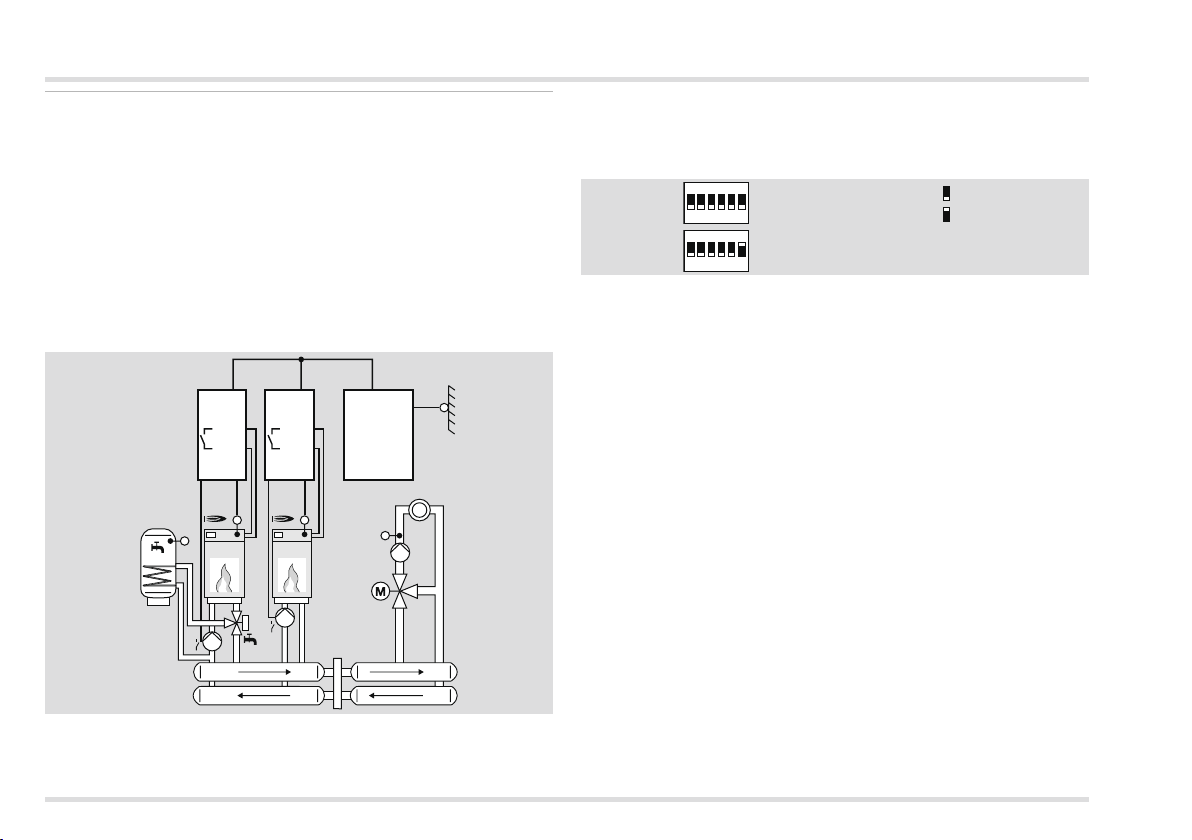
Internal hot water preparation of the first heat source in the
cascade (hydraulic separation)
Requirements
This mode of operation is automatically activated when
▷ a heat source sensor (KF/KFS) is connected and
▷ parameter 38 is assigned an address 1 to 88 (address heating
module).
In this application the relay for the hot water charging pump is used
for controlling the three-way valve for switching the heat source to
the hot water storage tank. The multifunction relay controls the heat
source pump.
#2
Lago
0321
T2 10
T1 9
420
KF
CAN-Bus
Merlin
AF
VF
SPF
#1
Lago
0321
T2 10
T1 9
420
KF
The factory settings apply for all other parameters, see page 32
(Expert – Set parameters) for explanations.
Set DIP switches
ON
1 2 3 4 5 6
ON
1 2 3 4 5 6
KF, SPF, VF, AF… (5 kΩ)
KFS, SPFS, VFAS, AFS… (1 kΩ)
= OFF
= ON
See page 31 (Expert – Set DIP switches) for explanation.
Set parameters
P30, P31, P32, P38, P80 = 05
30
Page 31
Expert – Set DIP switches
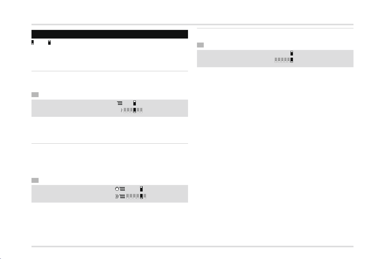
1 2 3 4 5 6
Expert – Set DIP switches
= OFF = ON
▷
The DIP switches 1 – 3 are now without function. The heating
circuit address of the mixer circuit is set via parameter 23, see
page 34 (P23 CAN bus ID mixer circuit (heating circuit address)).
Direct heating circuit or multifunction relay
The output on terminal 4 can be switched over between “Pump direct
heating circuit” and “Multifunction relay”.
• Use DIP switch 4.
Direct heating circuit
MFMultifunction relay
1 2 3 4 5 6
▷ If terminal 4 is to be used for the direct heating circuit pump, set
the heating circuit address 2 or higher for the mixer circuit because
the direct heating circuit occupies address 1.
Assigning a remote control FBR to the direct heating
circuit or mixer circuit
A connected remote control FBR2, a connected room sensor or
room thermostat can be assigned to the direct heating circuit or
the mixer circuit if the system is operated with two heating circuits.
• Use DIP switch 5.
Direct heating circuit
Mixer circuit
Set sensor resistance
The heating controller can be operated with 5 kΩ or 1 kΩ sensors.
• Use DIP switch 6.
1 kΩ PTC
5 kΩ NTC
123456
▷ Only sensor of one type may be used.
31
Page 32
Expert – Set parameters
Expert – Set parameters
▷
Parameters P1 to P19 for User, see page 12 (User – Set parameters)
WARNING
Incorrect settings can cause malfunctions and damage the heating
installation! Only a qualified expert may change the parameters
from no. 21.
▷ A code number must be entered via parameter P20 to change
parameters P21 and higher.
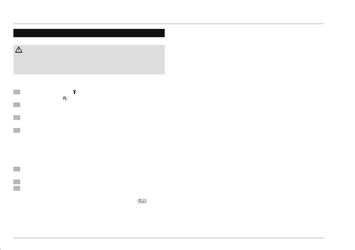
1 Turn selector switch to
▷ The display shows .
Turn the rotary knob until the parameter you want to change or
retrieve appears on the left in the display: 21 to 99.
Press the OK button.
▷ The indicator jumps to 20 0000. The first digit flashes.
4 Enter code no. (factory setting is 0000).
▷ Set each digit with the rotary knob and press the OK button.
▷ The display jumps back to the parameter to be changed.
▷ Display flashes if the correct code no. was entered. (The display
does not flash if the code no. was not entered correctly. Continue
with step 3.)
5 Use the rotary knob to set the desired value.
▷ A number of parameters can only be displayed.
6 Press the OK button to confirm.
7 After you have made your settings, continue with step 2 if you
want to change further parameters (you do not need to enter the
code no. again), or turn the selector switch back to .
▷ The table on page 33 (List of parameters P20 to P99) shows the
possible settings.
▷
Our heating controller will only display those parameters for which
there are sensors connected.
(Parameter setting).
32
Page 33
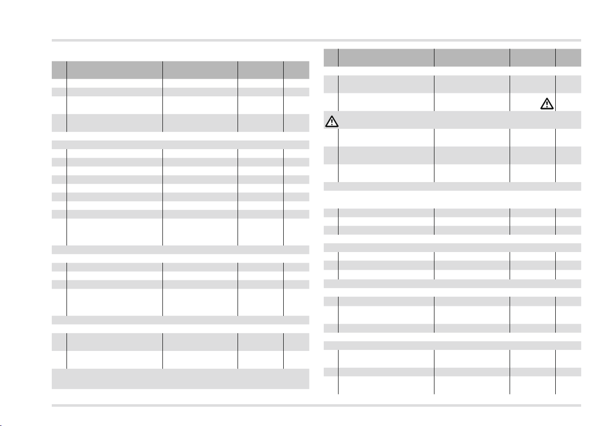
Expert – Set parameters
List of parameters P0 to P99
P.
Parameter Setting range
no.
20 Code no. input 0000 – 9999 0000
21 Code no. 0000 – 9999 0000
Outside temperature
22
Frost protection
23 CAN bus ID mixer circuit
With active heat source (HS) (boiler module/heating module)
30 Maximum temperature HS 30.0 – 110.0 °C 85.0 °C
31 Minimum temperature HS 10.0 – 80.0 °C 40.0 °C
32 Warm Up Temp 10.0 – 80.0 °C 35.0 °C
33 Minimum limiter HS 0, 1, 2 1
34 Dyn. switching hysteresis 5.0 – 20.0 K 10.0 K
35 Hysteresis time 0 – 30 min 0 min
36 Burner starts Display only
37 Burner running time Display only
Address heating module
38
(only for cascade
operation)
With active hot water function
50 DHW Relief 0, 1 1
51 Parallel pump operation 0, 1 0
52 Antilegion function 0, 1 1
Temperature increase
53
during hot water
preparation
With active direct heating circuit
Maximum flow tempera-
60
ture direct heating circuit
Minimum flow temperature
61
direct heating circuit
----,
-15.0 to +5.0 °C
1 – 15 (2 – 15 with
direct heating circuit)
----, 1 – 8 ----
0.0 – 50.0 K 20.0 K
20.0 – 110.0 °C 80.0 °C
10.0 – 110.0 °C 10.0 °C
Factory
setting
0.0 °C
2
Own
values
P.
Parameter Setting range
no.
With active mixer circuit
Additional mixer functions
69
(P77 – 79)
Maximum flow tempera-
70
ture mixer circuit
With underfloor heating, set parameter 70 according to manufacturer‘s specifications.
Minimum flow temperature
71
mixer circuit
72 Mixer Dynamic OPEN
73 Mixer Dynamic CLOSED
In combination with heating system controllers with active cooling
function
74 T-Flow Cooling 0, 1, 15.0 – 25.0 °C 15.0 °C
75 T-Room Cooling ----, 20.0 – 40.0 °C 25.0 °C
76 Min TO Cooling ----, 0.0 – 40.0 °C 27.0 °C
P77 – 79 can only be adjusted if P69=1
77 Mixer scan time 10 – 200 s 100 s
78 Mixer operating time limit ----, 0 – 30 min
79 Mixer start seconds 0 – 30 s
With multifunction relay (MF Relay)
80 MF Relay function 0 – 34
MF Relay switching
81
temperature
82 Hysteresis of the MF Relay 2.0 – 10.0 K 5.0 K
Service
PC enable (0000 =
97
disabled)
98 Relay Test 0, 1 – 6 0
Software version and
99
index (63.XX)
0, 1 0
20.0 – 110.0 °C
10.0 – 110.0 °C 10.0 °C
5.0 – 25.0
(P69=1: 5.0 – 200.0)
5.0 – 25.0
(P69=1: 5.0 – 200.0)
30.0 – 90.0 °C 30.0 °C
0000 – 9999 0000
63.00 – 63.99 Display only
Factory
setting
80.0 °C
16.0
(P69=1: 50)
12.0
(P69=1: 20)
---0 s
0
Own
values
33
Page 34

Expert – Set parameters
Explanation of the parameters
P0 Code no. input
Here the code number defined via P21 is entered for adjustment of
the Expert parameters.
▷ The factory setting for the heating controller is 0000.
P1 code no. change
Here you can specify your own code no. Remember this code well!
The parameters 21 – 99 can not be changed without this code no.
Should you forget the code no., the factory settings must be reloaded, and this means that all your settings will be lost, see page
12 (Load factory settings (Reset)).
• Change every digit of the four-digit code no. and confirm by
pressing the OK button.
P Outside temperature frost protection
P22 = ----: Frost protection is deactivated.
P22 = -15.0 to +5.0 °C: When the outside temperature drops below the set value, the heating circuit controller switches the heating
circuit pumps on.
P CAN bus ID mixer circuit (heating circuit address)
P23 = 1 – 15: It is possible to assign an address from 1 to 15 to the
mixer circuit. If the direct heating circuit is activated via DIP switch 4,
you must set an address of 2 – 15 for the mixer circuit because the
direct heating circuit automatically receives the address 1.
▷ Do not assign a heating circuit address more than once.
▷ When replacing a controller, always set the same address as the
original controller.
With active heat source (boiler module/heating module)
P0 Maximum heat source temperature
P30 = 30.0 – 110.0 °C: The heat source is heated to the maximum
of P30.
Protects the heat source from overheating and prevents triggering
▷
the Safety-Temperature-Limiter (LIMITER).
▷ Limiting the maximum temperature saves energy.
▷ Also has an effect on the hot water preparation.
▷ Settings according to boiler manufacturer’s specifications.
P1 Heat source minimum temperature
P31 = 10.0 – 80.0 °C: Set the parameter so that the formation of
condensation is prevented in the heat source when there is a low
heating requirement. The heat source does not switch off before P31
+ Switching hysteresis (P34) has been reached when heating up.
▷ Settings according to boiler manufacturer’s specifications.
P Warm-Up Temp
P32 = 10.0 – 80.0 °C: The heating controller switches the heating
circuit pumps off and closes the mixer until the heat source has
reached the temperature P32 when heating up.
▷ This reduces operation within the condensation range.
▷ Settings according to boiler manufacturer’s specifications.
P Minimum limit heat source
Reduces the formation of condensation in the heat source when there
is a low heating requirement. The heating controller does not switch
off before the minimum temperature (P31) + Switching hysteresis
(P34) has been reached.
P33 = 0: The minimum limit is switched off.
P33 = 1: The heat source maintains at least the set minimum temperature (P31) + Switching hysteresis (P34) during any heating time.
34
Page 35
Expert – Set parameters
P33 = 2: The heat source maintains at least the set minimum temperature (P31) + Switching hysteresis (P34) for 24 hours (including
setback mode times).
P4 Dynamic switching hysteresis
P34 = 5.0 – 20.0 K: The switching hysteresis is added to the Minimum Temperature (P31) of the heat source to calculate the actual
switch-off value.
P5 Hysteresis time
This function optimises heat source operation when subjected to
varying loads.
P35 = 0: The switching hysteresis (P34) is not reduced.
P35 = 1 – 30 min: The switching hysteresis (P34) is reduced to a hysteresis of 5K after the heat source is switched on and P35 has elapsed.
▷
When there is little removal of heat, set a long period for P35. This
prevents frequent pulsing of the heat source.
▷ Set a short period for P35 when there is a high removal of heat.
This avoids heating up the heat source to unnecessarily high
temperatures. The energy consumption of the heating system
is optimised.
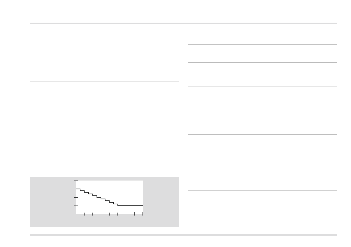
Example: Hysteresis time
P34 = 15, P35 = 10
20
15
P34 [K]
10
5
246810 12 14 16
P35 [Min.]
The initial switching hysteresis is reduced from 15 K to 5 K after 10
minutes.
P6 Burner starts
P36 shows the number of burner starts (no setting possible).
P7 Burner operating time
P37 shows the entire burner operating time in hours (no setting
possible).
P8 Address heating module (only for cascade operation)
P38 = ----: individual heat source (no cascade)
P38 = 1 – 8: In a cascade the heating controller is addressed under
the address specified.
With active hot water function
P50 DHW Relief (charging pump lock)
P50 = 0: The charging pump lock is switched off.
P50 = 1: The heating controller only switches the storage charging
pump on when the heat source temperature exceeds the storage
temperature by 5K. The controller switches the pump off as soon as
the heat source temperature drops below the storage temperature.
▷ This prevents the storage from being cooled by the heat source
at the beginning of hot water preparation.
P51 Parallel pump operation
P51 = 0: Hot water priority mode; During hot water preparation the
heating circuit pumps switch off the mixer valves close.
P51 = 1: Parallel pump operation; During hot water preparation the
heating controller only disables the direct heating circuit. The mixer
circuit continues to be heated.
35
Page 36

Expert – Set parameters
▷ This function extends hot water preparation.
P5 Antilegion function
P52 = 0: Protective function switched off.
P52 = 1: As a protective measure against thermoresistant bacteria, the hot water storage tank is heated to 65 °C with every 20th
heating-up process or at least once per week on Saturday at 01:00.
P5 Temperature increase during hot water preparation
P53 = 0.0 – 50.0 K: The heat source is operated at increased temperature during hot water preparation to ensure that the hot water
temperature is reached quickly via the heat exchanger.
The heat source desired temperature during hot water preparation
▷
= Desired hot water temperature + P53.
With active direct heating circuit
P60 Maximum flow temperature direct heating circuit
P60 = 20.0 – 110.0 °C: The heating controller limits the calculated
desired flow temperature of the direct heating circuit to P60 to protect
the consumer from overheating.
▷ Only when the temperature of the heat source exceeds P60 by
8K does the heating controller switch off the heating circuit pump
of the direct heating circuit. The controller will switch the heating
circuit pump back on as soon as the heat source temperature
drops below P60 + 5 K.
P61 Minimum flow temperature direct heating circuit
P61 = 10.0 – 110.0 °C: The heating controller increases the calculated
desired flow temperature of the direct heating circuit to P61, when
air heating is installed for example.
With active mixer circuit
P69 Additional mixer functions (P77 – 79)
P69 = 0: The additional mixer functions (P77 – 79) are deactivated.
Instead, the mixer is operated with default settings. This means
that the heating controller computes a correction value for the mixer
position every 10s (scan time).
▷ Settings when motor-driven roller wheel mixers are used.
P69 = 1: P77 – 79 can be set.
▷ Settings when motor-driven lifting valves are used.
P70 Maximum flow temperature mixer circuit
P70 = 20.0 – 110.0 °C: The heating controller limits the calculated
desired flow temperature of the mixed heating circuit to P70 to
protect the consumer from overheating, e.g. when an underfloor
heating system is installed.
P71 Minimum flow temperature mixer circuit
P71 = 10.0 – 110,0 °C: The heating controller increases the calculated
desired flow temperature of the mixed heating circuit to P71, e.g.
when air heating is installed.
P7 Mixer Dynamic OPEN (when opening)/
P7 Mixer Dynamic CLOSED (when closing)
P72/73 = 5.0 – 25.0 (when P69 = 1; 5.0 – 200.0):
The Mixer Dynamic determines the ratio between switch-on and
switch-off times of the mixer when opening or closing the mixer.
Depending on the deviation between desired and actual flow temperature, the mixer is actuated for a longer or a shorter period. The
ratio is based on a scan rate of 10s.
▷
Lower values cause fast mixer movement and can result in vibration.
36
Page 37
Expert – Set parameters
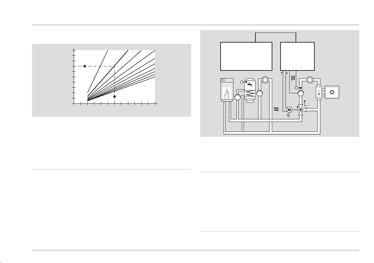
Example: Mixer Dynamic OPEN
P72 = 8
10
9
8
7
6
On-period [s]
5
4
3
2
1
1 2 3 4 5
5 8 10 12
6 7 8 9 10 11 12
Control deviation [°K]
14
16
18
20
22
24
In the case of a controller deviation of 6 K the mixer is actuated for
7s and remains switched off for 3s.
In combination with heating system controllers with active
cooling function
As a requirement for cooling mode, the central controller (e.g. Merlin)
must activate the “Cooling” operating mode.
74 T-Flow Cooling (flow temperature Cooling)
P74 = 0: The heating circuit is not cooled. The mixer in the heating
circuit remains closed, the heating circuit pump is switched off.
P74 = 1:
CAN-Bus
Merlin
Lago 0321
587
OFF
2
2
21
2
VF
ON
The mixer in the heating circuit functions as a valve. The mixer
opens (ON). The heating circuit pump is switched on.
P74 = 10.0 – 25.0 °C: The mixer controls to the set flow temperature
P74 of the heating circuit, see page 38 (Example: Cooling Operation).
P75 T-Room Cooling (desired room temperature)
Room temperature guided cooling
P75 = ----: The heating controller does not control according to
desired room temperature.
P75 = 20.0 – 40.0 °C: The heating controller starts cooling mode
of operation as soon as the temperature exceeds the set desired
room temperature P75. Cooling mode ends when the temperature
drops below P75 by 2K.
P76 Min TO Cooling (Minimum outside temperature for cooling)
Weather-guided cooling
37
Page 38
Expert – Set parameters
P76 = ----: The heating controller does not control guided by the
weather.
P76 = 0.0 – 40.0 °C: The heating controller starts cooling mode
of operation as soon as the temperature exceeds the set outside
temperature P76. Cooling mode ends when the temperature drops
below P76 by 1 K.
If values have been defined for P75 as well as P76, both conditions
must be met for cooling mode to start.
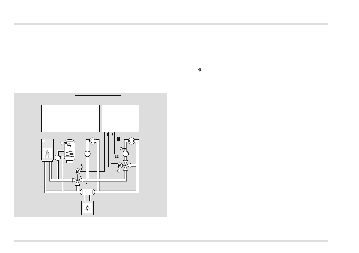
Example: Cooling Operation
CAN-Bus
Merlin
OFF
ON
Lago 0321
54 87
21
2
VF
2
2
hot water preparation and the direct heating circuit. The Lago 0321
controls the bypass valve and the mixed heating circuit.
P80 = 34, P74 = 20 °C
As soon as the central controller activates “Cooling” mode, the multifunction relay in the Lago0321 responds and opens the bypass
valve (ON) so that the cooling circuit is separated from the heat source.
The mixer 2 controls to the set flow temperature P74.
P77 – 79 can only be adjusted if P69=1
The parameters P77 – 79 are required when a motor-driven elevating
mixer is used.
P77 Mixer scan time
P77 = 10 – 200 s: The flow temperature is measured in cycles after
P77 has elapsed respectively.
▷ The longer the pipes the higher the value for P77 should be set.
P78 Mixer operating time limit
P78 = ----: Limit in the direction CLOSED = 10min, limit in the
direction OPEN = none
P78 = 0: No limit in either direction
P78 = 1 – 30 min: The value specifies the maximum length of time
that the mixer is operated in one direction (OPEN or CLOSED).
▷
This is important when the mixer is not equipped with a safety-
friction clutch or limit switches.
After the mixer has moved in one direction for the specified period,
▷
the mixer will not be controlled in the same direction until there
has been a control process in the opposite direction.
▷ Settings according to mixer manufacturer’s specifications.
The central controller activates the “Cooling” operating mode via the
CAN bus and controls the heat source, the refrigerating machine, the
38
Page 39

Expert – Set parameters
P79 Mixer start seconds
P79 = 0 – 30 s: The first stroke of a closed mixer does not immediately
effect a change in the flow temperature. P79 is the time that elapses
until a change in flow temperature can be measured.
▷
Increase this value if the flow temperature changes too slowly
during the initial stage.
With multifunction relay (MF Relay)
The multifunction relay (terminal 4) is active with the setting DIP
switch4 = “OFF”. The sensor on terminal 19 is assigned to the relays.
P80 MF Relay function
P80 = 0: without function
P80 = 1: Header pump (only when the Lago0321 is used as a
heating system controller)
▷
The header pump is switched on when a consumer requests heat.
▷
When there is no heat request, the pump is switched off. The pump
runs on for 5 minutes after the heat source has been switched off.
P80 = 2: The circulation pump is switched on simultaneously with
the hot water program.
▷ A storage sensor must be installed in the system.
P80 = 3: Feed pump
▷
The feed pump is switched on when an internal consumer re-
quests heat.
▷
When there is no heat request, the pump is switched off. The pump
runs on for 5 minutes after the heat source has been switched off.
P80 = 5: Heat source pump
▷
The multifunction relay switches in combination with the burner
relay (T1 – T2), run-on = 5 min
P80 = 20: Temperature-controlled circulation pump
T-CIRCL = Return flow temperature of the circulation line (measured
by the multifunction sensor)
▷
The circulation pump is switched on when T-CIRCL < P81, i.e.
when the return flow temperature is lower than the switching
temperature of the multifunction relay (set via P81).
▷ The pump is switched off when T-CIRCL >P81 + P82, i.e. when
the return flow temperature is higher than the switching temperature of the multifunction relay (set via P81) plus hysteresis (P82).
▷ The pump can only be switched on during the switch-on times
of the hot water program (P18).
P80 = 21: Circulation pump via pulse
▷ The circulation pump is switched on for 5 minutes when there is
a short-circuit between terminal 19 and GND.
▷ The pump can only be switched on during the switch-on times
of the hot water program (P18).
P80 = 24: Return flow booster, heat source
T-RETURN= Return flow temperature of the system (measured by
the multifunction sensor)
▷
The pump for the return flow boost is switched on when T-RETURN
< P81, i.e. when the return flow temperature is lower than the
switching temperature of the multifunction relay (set via P81).
▷
The pump is switched off when T-RETURN >P81 + P82, i.e. when
the return flow temperature is higher than the switching temperature of the multifunction relay (set via P81) plus hysteresis (P82).
39
Page 40
Expert – Set parameters
P80 = 34: Bypass valve in cooling mode
▷
The multifunction relay witches as soon as a central controller, e.g.
Merlin, activates the operating mode “Cooling”.
▷
During cooling mode hot water preparation is possible by means
of conventional heat sources.
▷
Example see page 37 (P76 Min TO Cooling (Minimum outside
temperature for cooling)).
P81 Switching temperature of the multifunction relay
P81 = 30.0 – 90.0 °C: Switching requirements: see page 39 (P80 MF
Relay function).
P8 Multifunction relay hysteresis
P82 = 2.0 – 10.0 K: The multifunction relay is switched off when the
measured temperature is greater than P81 + P82.
Service
P97 PC enable (0000 = disabled)
P97 = 0000 – 9999: Unlock code that can be used to retrieve data
from the mixed heating circuit by means of the PC software “ComfortSoft”.
• Change every digit of the four-digit code no. and confirm by
pressing the OK button.
P98 Relay Test
The relay test is used to check the electrical connection.
Each relay output is actuated one after the other by changing the
parameter values. The corresponding output is shown in the display.
P98 = 0: No relay is controlled
P98 = 1: Heating circuit pump Direct heating circuit / multifunction
relay (terminal 4)
P98 = 2: Heating circuit pump Mixed circuit (terminal 5)
P98 = 3: Storage charging pump (terminal 6)
P98 = 4: Mixer Open (terminal 7)
P98 = 5: Mixer Closed (terminal 8)
P98 = 6: Burner electrically isolated (terminals 9 – 10)
Perform relay test
▷ Turn the selector switch back to
1 Turn selector switch to (parameter setting).
▷ The display shows PL.
Turn rotary knob until 98 0 appears in the display.
Press the OK button.
▷ Display jumps to 20 0000. The first digit flashes.
4 Enter code no. (factory setting 0000). To do this, set each digit
using the rotary and press the OK button.
▷ Display jumps back to 98 and the 0 flashes. (If an incorrect code
number was entered, the display jumps back to 20 0000. Continue with step 4.)
5 Use rotary knob to select the desired relay output (1, 2, 3, 4, 5
or 6) to control.
▷ The controlled relay output flashes in the display.
6 Check the device connected to the relay output for active running.
▷ Continue with step 5 if further relay outputs need to be checked.
▷ After no more than 10 minutes control of the connected device
is terminated and the display of the relay to control jumps to “0”.
7 Press the OK button to terminate the relay test.
▷ Display jumps to 98 0.
8 Turn selector switch back to .
P99 Software version and index (6.XX)
P99 = 63.00 - 63.99
If you have questions about your heating controller, always specify
▷
the software version.
to cancel.
40
Page 41

Expert – Checklist for commissioning
❑
Heating controller properly wired? Particularly the bridges between
L and L1 and between GND and terminal 16, see page 21 (Connection diagram controller without socket) and page 22 (Connection
diagram controller with socket).
❑ Are the sensors required for the application connected?
❑ Sensors that are not required are not connected.
❑
DIP switch set correctly? See page 31 (Expert – Set DIP switches).
❑
User parameters configured? Set at least time and day of the
week, see page 8 (Set time and day of the week).
❑
Expert parameters configured? See page 32 (Expert – Set parameters).
❑ Sensors tested for plausible values? See page 8 (Display actual
temperatures).
❑ Relay outputs tested? See page 40 (P98 Relay Test).
❑ Operating mode set? See page 8 (Set operating mode).
❑ Selector switch turned to ?
Expert – Checklist for commissioning
41
Page 42
Service
Service
1 Remember the current operating mode.
Turn selector switch to “Mode”.
Press the OK button.
▷ Display flashes.
4 Rotate the rotary knob clockwise up to .
5 Press the OK button.
6 Perform service.
▷ The heat source heats to the max. temperature set via parameter
30. As soon as the temperature of 65 °C has been reached,
the consumers regulate to their max. flow temperature for heat
removal.
7 Press OK after you have completed the service procedure.
8 Use the rotary knob to set the mode back to the original operating
mode.
9 Turn selector switch back to .
▷ The heating controller resets the “Service” operating mode auto-
matically after 15 minutes.
STL Test
▷ You will find information on the trigger temperature of the STL in
the heat source manual.
▷
It is not necessary to disconnect the heating circuit pumps or the
mixer for the STL test.
▷ The boiler sensor must be connected.
1 Turn selector switch to “Mode”.
Press and hold the OK button.
▷
Display flashes and shows the actual temperature of the heat
source. The temperature rises for as long as the OK button remains pressed, up to the point that STL triggers.
Unlock the STL manually.
▷ If the STL does not trigger, replace STL.
▷
Once the OK button is released, the heating circuit pumps switch
on to remove heat.
42
Page 43
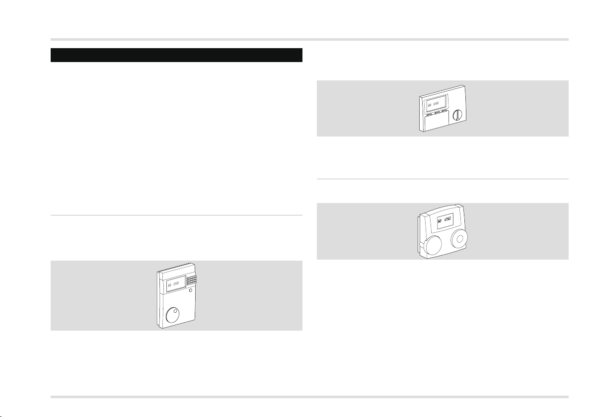
Accessories
Accessories
Operating module Merlin BM, BM8, or remote
control Lago FB
The controller supports the option to connect an operating module
via the CAN bus. With the operating module it becomes possible
to move various operating functions and the monitoring of system
values into the living space itself.
This makes operation very convenient. The technical information for
the operating module describe the full range of functions in detail.
▷ Display of the Expert parameters
▷ Input of User parameters
▷ Room temperature control
▷ Automatic adaptation of the heat slope (not for Lago FB)
Merlin BM
With plain text display in the language of the country; illuminated,
4-digit display; a button is allocated to every row, very convenient
to operate.
Instructions in German: Order no. 99 778 201
With instructions in language of your choice: Order no. 99 778 202
Installation and operation, see enclosed instructions.
BM 8
Plain text in language of the country and symbols in the display, operation with three buttons, easy setting of desired room temperature
with rotary knob, party button and mode selection.
Instructions in German: Order no. 99 678 736
With instructions in language of your choice: Order no. 99 678 738
Installation and operation, see enclosed instructions.
Lago FB
Operation as for heating controller Lago 0321.
Order no. D/D 99-678-868
Installation and operation, see enclosed instructions.
PC Adapter
For the communication between heating controller with bus and a PC.
The ComfortSoft program can be used to set and retrieve all system
parameters. In the PC the parameters can be saved, graphically displayed and evaluated within a specified time periods. The software
is available for download at www.docuthek.com. For a connection
to the PC the CoCo PC active is required, which, in combination
with a modem, also supports sending error messages via SMS
43
Page 44
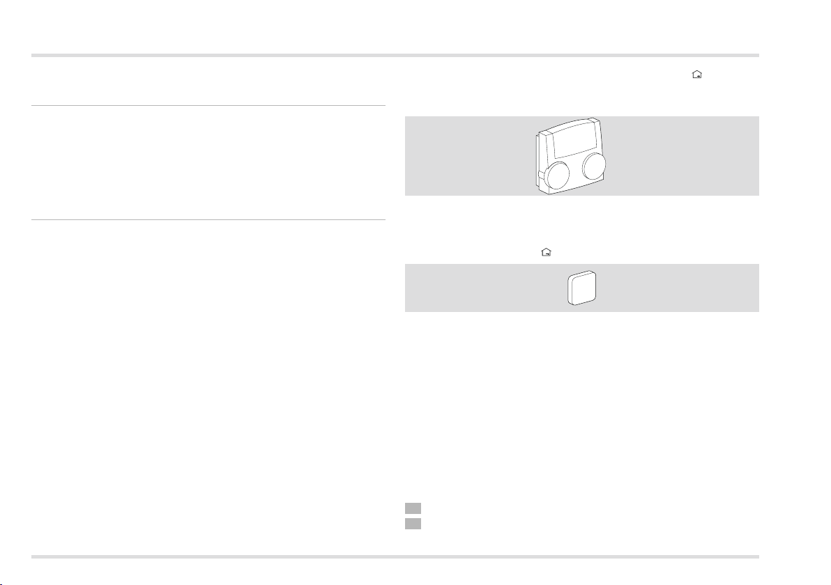
Accessories
and the remote retrieval of controller data. The CoCo PC mobile is
an alternative without remote retrieval or error messages via SMS.
CoCo PC active
Order no. 99 678 288
Scope of supply
CoCo PC active, instructions.
The connecting cable for the RS232 interface must be ordered sepa-
rately: Order no.: 99676894.
CoCo PC mobile
Order no. 99 677 961
Scope of supply
CoCo PC mobile, instructions, connecting cable to USB mini-B for
CAN bus or eBus.
On installation and operation, see enclosed instructions.
Remote control and room sensor FBR
Remote control for selecting the operating mode and setting the
desired room temperature
Order no. 99 679 161
Installation and operation, see enclosed instructions.
Room sensor RFB
Order no. 99 676 857
Scope of supply
Room sensor
Position of installation
▷ In the main living room of the heating circuit on an inside wall
▷ Not in the vicinity of radiators or other devices that give off heat
▷ Not covered by curtains
▷ Not influenced by draught
▷ The radiator valves in the room must be fully opened.
44
Installation
1 Remove upper part from base at the underside.
Screw base to the wall.
Page 45
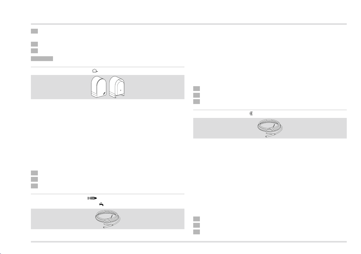
Accessories
Connect electrically, see page 18 (Expert - Electrical connec-
tions).
4 Press upper part back on.
5 Set parameter 10 or 15 on the heating controller.
Sensor
Outside sensor AF/AFS
Order no. AF, 5 kΩ: 99 679 030
Order no. AFS, 1 kΩ: 99 679 001
Scope of supply
Outside sensor, screw and dowel
Position of installation
▷ Ideally on a wall facing north or north-east
▷ Approx. 2.5 m above the ground
▷ Not above windows or air shafts
Installation
1 Pull cover off sensor.
Fasten sensor with enclosed screw.
Connect electrically, see page 18 (Expert - Electrical connections).
Boiler sensor KF/KFS
Storage sensor SPF/SPFS
Order no. KF/SPF, 5 kΩ, 3 m, ø 6.0x50:
99 676 769
Order no. KFS/SPFS, 1 kΩ, 3 m, ø 6.0x50:
99 676 682
Position of installation
In the immersion pipe of the hot water storage tank (usually on the
front side of the storage tank
Installation
1 Dry immersion pipe.
Insert the sensor as far as possible into the immersion pipe.
Connect electrically, see page 18 (Expert - Electrical connections).
Flow sensor VF/VFAS
Order no. VF, 5 kΩ, 3 m, ø 6.0x50: 99679073
Order no. VFAS, 1 kΩ, 3 m, ø 6.0x50: 99679051
Scope of supply
Flow sensor, thermal compound, retaining strap, instructions
Position of installation
▷ In the case of heating system control instead of boiler sensor KF,
as close as possible at the back of the boiler on the heater flow
▷ In the case of mixer operation approx. 0.5 m behind the heating
circuit pump
Installation
1 Thoroughly clean flow pipe.
Apply thermal compound to sensor.
Fasten sensor to the flow pipe with the retaining strap.
45
Page 46
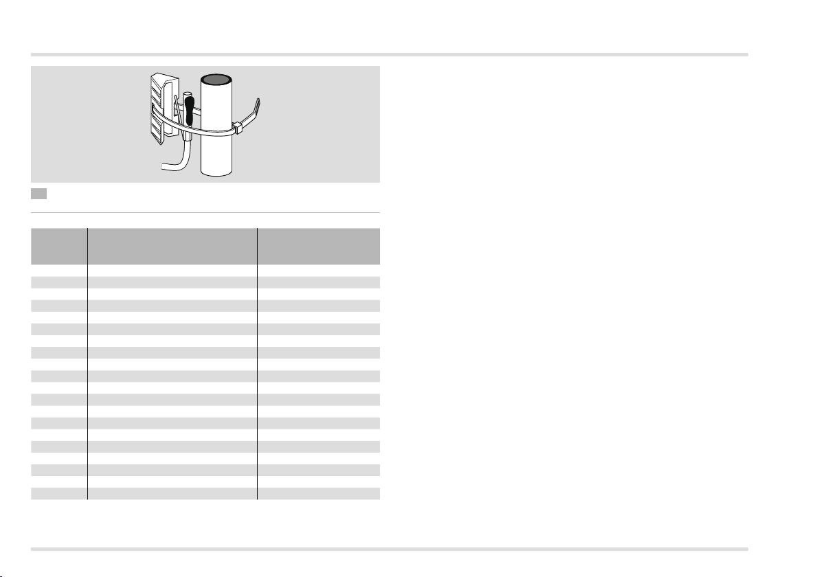
Accessories
4 Connect electrically, see page 18 (Expert - Electrical connections).
Sensor values
Temp.
[°C]
-60 698961 470
-50 333908 520
-40 167835 573
-30 88340 630
-20 48487 690
-10 27648 755
0 16325 823
10 9952 895
20 6247 971
25 5000 1010
30 4028 1050
40 2662 1134
50 1801 1221
60 1244 1312
70 876 1406
80 628 1505
90 458 1607
100 339 1713
110 255 1823
120 194 1936
▷ Only sensor of one type may be used.
5 kΩ NTC:
AF, KF, SPF, VF
[Ω]
1 kΩ PTC: AFS, KFS,
SPFS, VFAS
[Ω]
▷
Set the sensor type with DIP switch 6, see page 31 (Expert –
Set DIP switches).
▷ The sensor value of a remote control unit with room sensor FBR
or a room sensor RFB is detected automatically.
46
Page 47
Help with faults
Help with faults
? Fault
! Cause
• Remedy
When a fault occurs, the associated error number is indicated in
the display.
Fault Error no.
The mixer does not
start.
The heating circuit
pumps do not switch
off.
No more hot water
available.
The flat does not get
warm. No more hot
water available.
The multifunction
pump is off.
The flat gets too warm.
• Check electrical connection. Replace sensor, if necessary.
? The display shows error no. E 81.
! EEPROM error. An invalid parameter has been replaced by the
default value.
• Check parameter values.
• Switch mains power off and on again to reset the error no.
E 69
E 75
E 76
E 77
E 79
E 80
Defective sensor (break /
short-circuit)
Flow sensor mixer circuit
VF/VFAS
Outside sensor
AF/AFS
SPF/SPFS storage sensor
Boiler sensor
KF/KFS
Sensor for the multifunction
relay
Room sensor
? The display shows error no. E 91.
! The set CAN bus address is already used by a different device.
• Set parameter 23 to a different address that is not yet in use.
? All radiators and the hot water storage tank are cold. But the
heating controller display shows high temperatures.
? All radiators and the hot water storage tank are warm. But the
heating controller display shows low temperatures.
! DIP switch 6 set to wrong sensor type.
• Set DIP switch 6 correctly:
OFF = 5 kΩ sensor (KF, SPF, VF, AF…),
ON = 1 kΩ sensor (KFS, SPFS, VFAS, AFS…)
▷ Never mix 1 kΩ and 5 kΩ sensors.
? When displaying the actual values on the heating controller you
realise that the indicated value does not match the real one. For
example, the actual hot water temperature is 20 °C, but the display
shows 65 °C (or vice versa).
! 1 kΩ and 5 kΩ sensors have been mixed.
• Only use sensors with identical resistance values.
47
Page 48
Help with faults
? No actual values are indicated on the heating controller.
! No bridge between terminal 16 and GND.
• Check electrical connection, set bridge and load factory settings
on the heating controller (Reset).
? Although pumps and mixer are indicated on the display they are
not actuated.
! No bridge between terminals 2 and 3 or terminal 1 and neutral
block.
• Check electrical connection.
? The flat does not get warm.
! The heating circuits do not respond to the mode setting.
• Set parameters 08 and 13 = “----”.
! The heating times at the bottom of the display to not match the
desired heating program.
• Set parameter 19: P19 = 00 for direct heating circuit, P19 = 01
for mixed heating circuit.
• Set parameters 08 and 13 = “----”.
! Pump for direct heating circuit is not running.
• Set DIP switch 4 to “Pump direct heating circuit”.
? The hot water stays cold during summer mode.
! Parameter 18 = 03 set (hot water 1h before heating)
• Set P18 = 01 or 02.
Should the actions described above fail to help, please
contact your heating engineer.
▷ Please have ready the software version (parameter P99).
48
Page 49
Technical data
Mains voltage according to DIN IEC 60 038: ~230 V, ±10%
Power consumption: max. 5 VA
Switching capacity of the relays: ~250 V, 2(2) A
Max. current via terminal L1’: 6.3 A
Protection class according to DIN EN 60529: IP 40
Protection class according to DIN EN 60730: I
Reserve power of clock: >10 h.
Permissible ambient temperature during operation: 0 to 50 °C
Permissible ambient temperature during storage: -20 to 60 °C
Permissible relative humidity, not condensing: 95%r.H.
Sensor resistances: NTC 5 kΩ (AF, KF/SPF, VF),
Tolerance in ohms: ±1 % at 25 °C,
Temperature tolerance: ±0.2 K at 25 °C
Sensor resistances:
PTC 1010 Ω, (AFS, KFS, SPFS, VFAS)
Tolerance in ohms: ±1 % at 25 °C,
Temperature tolerance: ±1.3 K at 25 °C
Efficiency gain*
3,5% VII
* In accordance with Directive 2009/125/EC Communication 2014/C_207/02/
Controller
class
In combination with
Room temperature control
Outside temperature control
Staged boiler temperature control
Technical data
49
Page 50
Glossary
Glossary
Flow and return flow temperature
The flow temperature is the temperature to which the heat source
heats the water that transfers the heat to the consumer (e.g. radiator).
The return flow temperature is the temperature of the water that flows
back from the consumer to the heat source.
Desired and actual temperature
The desired temperature (or setpoint temperature) describes the
desired temperature for a room or for hot water.
The actual temperature denotes the actual temperature that prevails.
The heating controller has the task to adjust the actual temperature
to the desired temperature.
Setback temperature
The setback temperature is the desired temperature to which the
heating system heats outside heating times (e.g. at night). It should
be set so that the rooms do not cool down too much while saving
energy.
Heat source
Heat source is generally the designation for the heating boiler. It may
also be a buffer storage tank however.
Circulation pump
The circulation pump ensures that there is constant hot water avail-
able. The hot water is held in the storage tank. The circulation pump
circulates it via the fresh water pipes in accordance with the heating
program.
Return flow booster
The return flow booster prevents the temperature difference at the heat
source between flow an return becoming too great. A mixing valve is
here used to add a portion of the hot flow water to the return flow to
prevent condensation of the steam from the heating gas against the
cold heat carrier inside the heating boiler. The minimum temperature
required for this process inside the heating boiler depends on the
type of fuel (oil 47°C, gas 55°C). The risk of corrosion inside the
heating boiler is thereby reduced significantly.
Direct heating circuit
In the direct heating circuit the flow temperature is identical to the
heat source temperature, i.e. the direct heating circuit is operated
with the maximum temperature.
Mixed heating circuit / Mixer circuit
In the mixed heating circuit a three-way valve is used to add cooled
water from the return flow to the hot flow water. The flow temperature
is thus reduced. This is important for underfloor heating systems,
for example, because they must only be operated with low flow
temperatures.
Heating time
In the heating programs you can define up to three heating times per
day, one for the morning, one for lunchtime, and one for the evening
for example. During a heating time, the temperature is controlled to
the desired room temperature. Between heating times the temperature is controlled to the setback temperature.
50
Page 51
Certification
Header pump
A header pump is used to pump the hot water in a system with one
or several heat sources. It is switched on as soon as a consumer in
the system requests heat.
Feed pump
A feed pump functions like a header pump. It is switched on as soon
as an internal consumer in the system requests heat.
Legionella
Legionella are bacteria that live in water. The hot water storage tank
is heated to 65°C every 20th heating period or at least once a week
as protection against these bacteria.
Certification
Declaration of conformity
We the manufacturer declare the product Lago0321 is in conformity
with the fundamental requirements of the following directives and
standards.
Directives:
– 2014/35/EU
– 2014/30/EU
– 94/62/EG
– 2009/125/EG
– 1907/2006
Standards:
– EN 60730-1
– EN 60730-2-9
– EN 60335-1
– EN 60335-2-102
The manufacture is subject to the quality management system in
accordance with DIN EN ISO 9001.
Elster GmbH
Scan of the declaration of conformity (D, GB) – see
www.docuthek.com
Eurasian Customs Union
The product Lago 0321 meets the technical specifications of the
Eurasian Customs Union.
51
Page 52
Contact
Heating circuit allocation
For the installation expert
Please enter which rooms the heating circuits are assigned to here.
Direct heating circuit Mixed heating circuit
52
Kurt-Schumacher-Allee 2 · 28329 Bremen
https://www.brummerhoop.com
 Loading...