

Page 1
APPLICATION NOTE
Using Modems with Sound Level Meters
Sound Level Meters are often used for
monitoring in remote places, an d you
may want to “monito r the monit or” or
transfer measured data to your homebase PC, without go ing to the measurement sit e. A telephon e connect ion —
wired or wireless — is a convenient way
to transfer measurement data. And modems are a vital link in the chain of transmission. T his applicat ion note e xplains
what equipm ent you need and how to
use it.
Please note that only Brüel& Kjær Types
2236 and 22 60 are s up ported for m ode m
connection . Types 2231, 22 37 and 44 36
need spec ial handshak ing modes, w hich
cannot b e activated v ia modem.
Page 2
Using Modems with Sound Level Meters
2260 Semi-permanent Monitoring Kit
A sound level meter for monitoring in the field needs protection against
weather and tampering, and it needs a power supply other than its
internal batteries. Also, you need space and power for the modem.
For the Investigator Sound Level Analyzer Type 2260, the 2260 Semi-
permanent Monitoring Kit is available. It includes a weatherproof case,
12V battery, battery charger, cables, Outdoor Microphone Kit and software for Type 2260 and for the PC. The case has room for all the
equipment including a modem, and it has a cable entry for feeding
external power to the system. A complete system including the 2260 is
also available: the 2260 Semi-permanent Monitoring System has all the
equipment in the Kit, plus the 2260, a calibrator, a tripod and an inter-
face cable for a PC. For ordering information, see the “Noise Monitoring”
System Summary sheet (BU 3063).
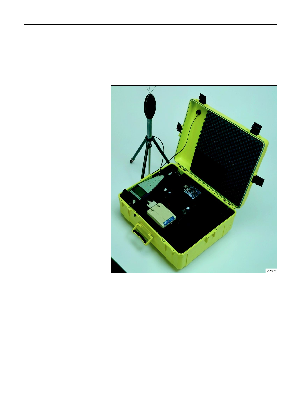
Fig.1 2260 Semi-permanent Monitoring
System
2
Page 3
Standard Modems
Fig. 2 Field equipment shown with
standard modem. The telephone line
connector is shown in the lid
This section shows how to c apture sound measurements from a remote
Sound Level Analyzer (I nvestigator Type 2260) via telephone lines and
standard modems. Precision Integrating Sound Level Meter Type 2236
may als o be used.
The field equipment is illustrated in Fig. 2.
3
Page 4
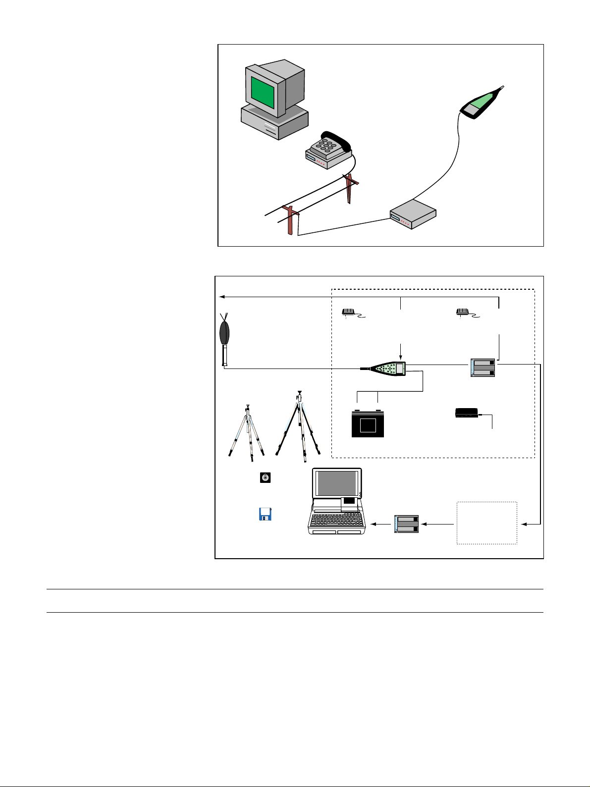
Fig. 3 Stan dard modem set-up
Fig. 4 System dia gram. The d iagram
does not include the optional DAT recorder
B&K 2236
or 2260
Hayes ¤ Compatible
PC running
Evaluator
Type 7820
Modem
Dumb Auto
Answer Modem
(Multitech MT 2834ZDX)
980001e
Fig. 4 shows the complete system including the home-base modem.
Mains Power
Outdoor Microphone Kit UA 1404
(Preamplifier ZG 0026 and
Microphone 4189, from 2260)
Microphone Extension Cable
AO 0441 (3m)
AO 0442 (10m)
Lightweight
Tripod
Tripod
UA 0587
UA 0801
Mains Power Supply
ZG 0386 (EU)
ZG 0387 (UK)
ZG 0388 (US)
Sound Level Analyzer
Type 2260
+
Panasonic
dflkfpojmmljflkjgjrg
grmowjgfpktjpw
dB
–
12V Battery
QB 0051
0
?
Brüel & Kjær Type 2260
Cable for
12V Supply
Battery Charger
Mains Adaptor
(included with
Multitech Modem)
MT2834ZDX
Field modem
Multitech
ZG 0404
Case Type 3592
Sound Level
Calibrator 4231
Evaluator 7820
Community noise
calculations
Standard Modems — Field Modem
The modem used in the field must be intelligent enough to provide
error correction, but dumb enough not to interpret any of the communication nor to add anything by sending messages to the sound level
meter (see APPENDIX 1: Selection of Field Modem).
Testing a number of modems, Brüel&Kjær has found the Multitech
MT2834ZDX to be the best choice, and recommends only that for field
use.
Brüel& Kjær doe s not provide technical support for other modems.
4
TOSHIBA
Notebook/PC
Home-base Modem
®
Hayes
compatible
Telephone
system
970551e
Page 5

Table1 Equipment Equipment Type Available From
®
PC operating system Windows 95
WindowsNT4.0
Windows
PC-modem cable Depends on modem and PC Modem or PC
Home-base modem Hayes
®
e.g. Multitech MT2834ZDX
,
®
®
compat ible
,
3.10 or 3.11
PC supplier
supplier
Modem supplier or
Brüel& Kjær
(ZM0069)
Field modem Multitech MT2834ZDX Modem supplier or
Modem power Mains adaptor (supplied) or
9VDC
SLM-modem cable AO 0567 Brüel &Kjær
SLM 2260 (or 2236) Brüel & Kjær
SLM power 12 V DC from QB 0051 or
Mains Power Supply
ZG 0386 (EU)
ZG 0387 (UK)
ZG 0388 (US)
2260 Semipermanent
Monitoring Kit
BZ 7202 –302 (English)
BZ 7202 –303 (French)
BZ 7202 –304 (German)
BZ 7202 Enhanced Sound
Analysis SW
3592 Outdoor Gear
UA1404 Outdoor Microphone
Kit
AO 0441 Microphone
Extension Cable (3 m)
QB 0051 12 V Battery
AQ 1698 Cable for 12 V Supply
ZG 0404 Battery Charger
AQ1700 Cable for DAT Remote
AO 0543 DAT Signal Cable
7820 – 002 Evaluator (English)
7820– 003 Evaluator (French)
7820– 004 Evaluator (German)
Brüel& Kjær
(ZM0069)
Brüel &Kjær
Brüel &Kjær
Brüel &Kjær
Lightweight Tripod
Tripo d
Sound Level
Calibrator
UA 0801
UA 0587
4231 Brüel & Kjær
Brüel &Kjær
Setting u p the Field Modem
The Multitech modem is configured from the factory to be used as a
®
Hayes
compatible modem together with your PC. In order to get this
modem to work in the field you must do some programming of the
modem.
Begin by connecting the Multitech modem to COM1 or COM2 on your
PC, then start the Evaluator application. Choose Options… on the Tools
menu. Next select the Modem tab. On the modem droplist select User
Defined Modem, then set the actual COM-port where you have connected
the Multitech modem. Finally set the Baud Rate to 19200.
5
Page 6
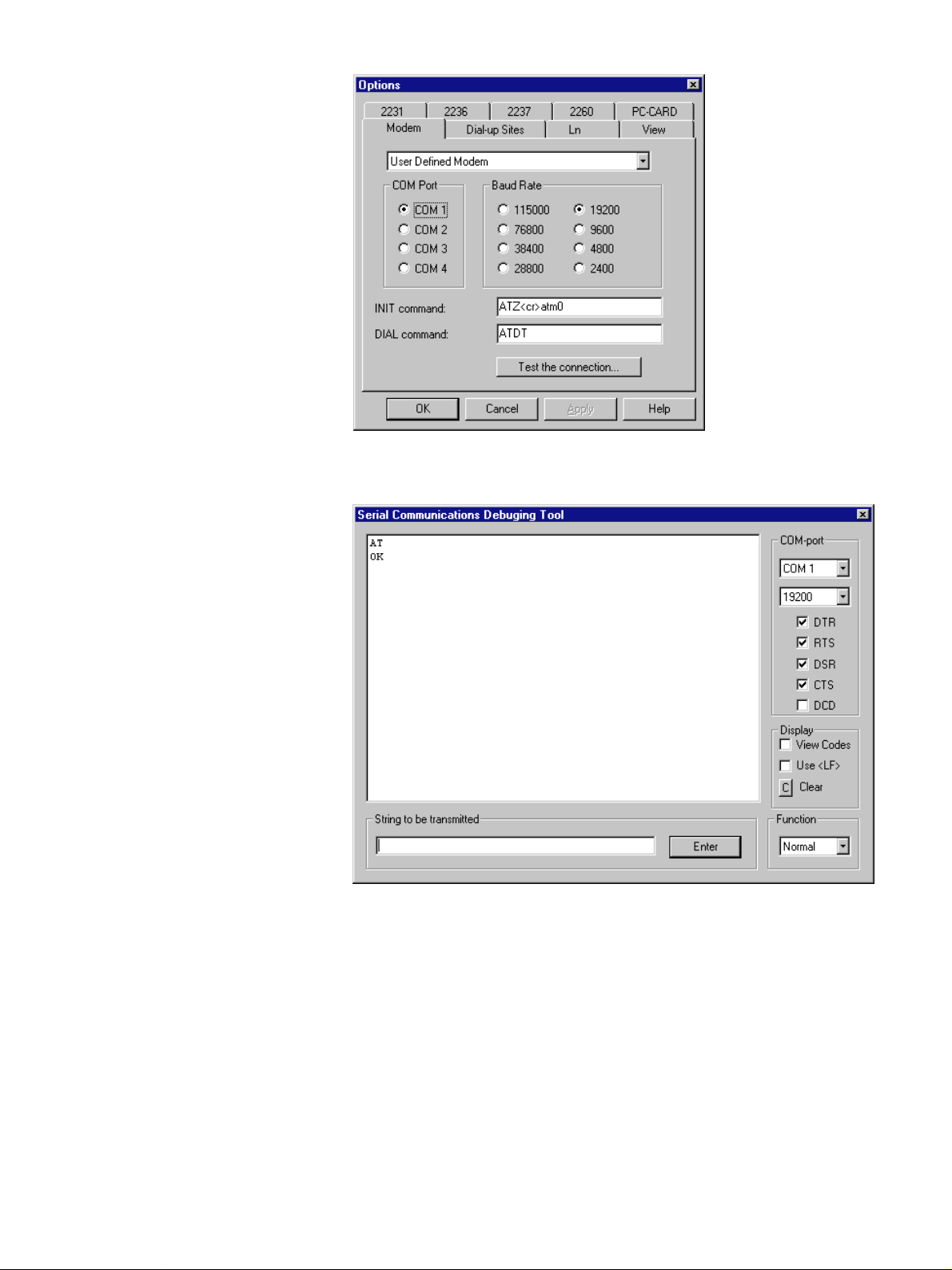
Click on the Test the conne ction… button to launch the Serial Commu-
nications Tool.
If your modem is properly connected to the PC, all the status indicators
except DCD should show ✓. To verify that the modem is recognized
enter the letters A and T in the String to be transmitted box and click
on the Enter button. The modem should then reply OK.
If your modem has reacted as described above, you can go on with the
programming of the modem. Enter the commands one bye one from
Tab le 2 into the String to be transmitted box and click on the Enter
button after each command:
All 0 charact ers on the list are ze ros. Plea se note th at this list of co m-
mands is only valid for the Multitech modem. It is not guaranteed to
work with other types of modems.
Now the Multitech modem can be connected to the SLM in the field.
Use cable AO 0567 which is a straightforward extension cable (male/
6
Page 7
Tab le2 Commands for the Mu ltitech
modem
Enter command Significance
ATM0 Speaker off
ATE0 No Echo
AT%E0 No Escape Sequence
ATS0=1 Answer in coming c alls aft e r first r i n g
AT$SB19200 Lock the baud rate to the SLM to
19200 bits/sec
ATQ1 No Result codes
AT&W0 Write the new configuration to the
modem non volatile memory
female 25-pin/9-pin cable with all lines in 1–1 conne ction) — Do not us e
the Brüel & Kjær AO 1386 cable in this case!
Setting up the 2236 for Modem Transfer
1. Press the <Show> button 9 times until the display shows INTERFACE.
2. Press the <Edit> button.
3. Press the or <Parameter> button until the display shows
19200 Baud.
4. Press the or <Level> button.
5. Press the or <Parameter> button until the display shows
Hardwire.
6. Press the <OK> button twice.
Now your 2236 has the right communication set-up and you can con-
tinue to set up the measuring parameters. As the Evaluator can only
remote control 2236 to start and stop measurements via the Autolog to
log command, you must start the initial log by specifying the sampling
interval, for example, Autolog to log every 1 min.
Setting up the 2260 for Modem Transfer
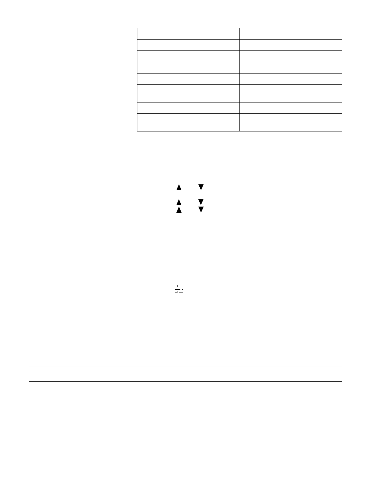
1. Press the button to enter the Setup s creen.
2. Press the <Setup Menu> softkey.
3. Us e the ❒ soft key to move down and select PC communication.
4. Set the baud rate to 19200.
5. Press <Save>.
After having programmed the communication parameters you must se-
lect the desired measurement set-up. Please refer to your 2260 User
Manual for information.
Standard Modems — Home-base Modem
Most modems available for use with a PC will do well for the homebase m odem. It m ust fulfi l the follow ing require ments:
❍ It must be Hayes compatible (supporting the AT command set)
❍ The DCD (Da ta Carrier Detect) line must indicate the actual connec-
tion state
❍ The modem must disconnect whenever the DTR (Data Terminal
Read y) line goe s false
❍ The modem must provide correction of transmission errors
7
Page 8
Setting up the Home-base Modem
After connecting the modem to your PC using the modem-PC cable, you
can configure the PC software. If you use Windows95 or
WindowsNT4.0, you must install the modem via the control panel in
Windows first.
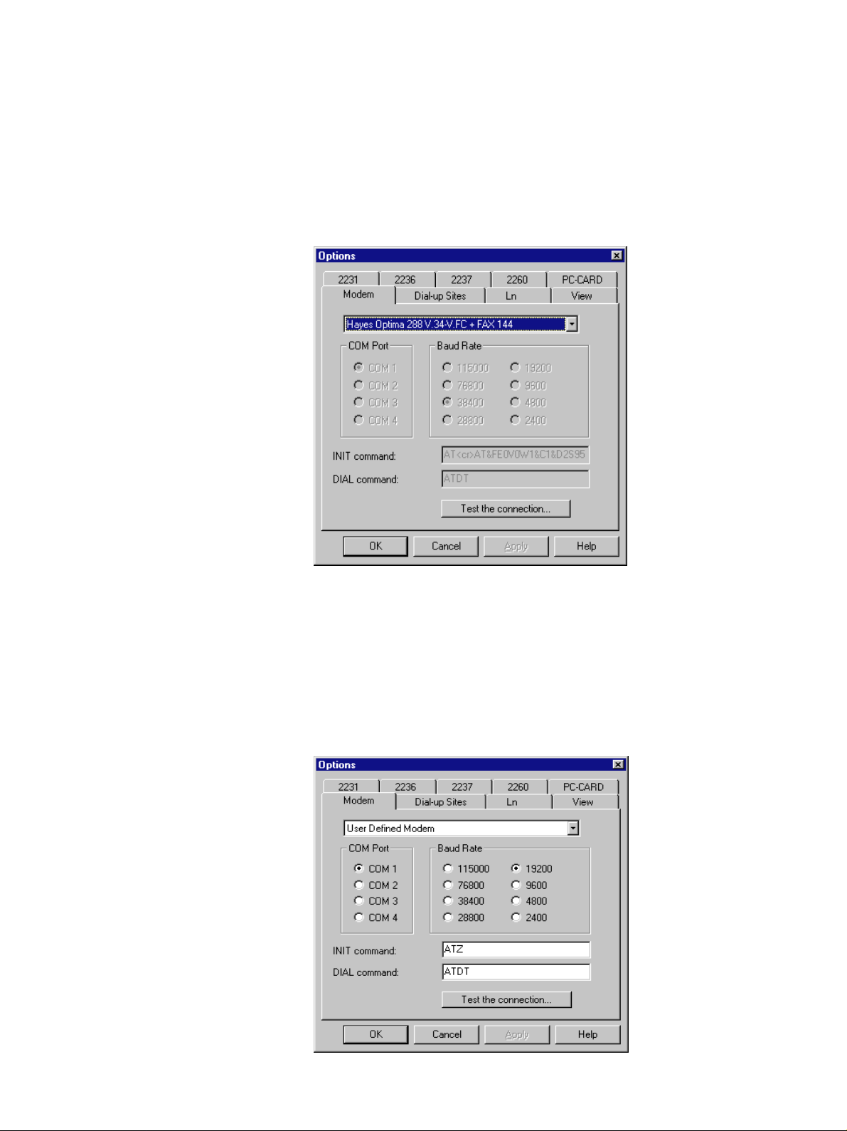
Start the Evaluator Type 7820. Choose Options… on the Tools menu.
Next select the Modem tab. Again if you use Windows 95 or NT4.0, you r
modem is already known by the system, so all you have to do is select
it on the drop-down list.
If you want to test the connection to the modem, you can click on the
Test the connecti on… button, whereby you launch the Serial Communications Debugg ing Tool. On this screen you can test the modem connec-
tion by selecting the Te s t M o de m in the Funct ion bo x in th e lowe r righ t
corner.
If you use Windows 3.10 or 3.11 or if you have problems getting your
modem to work under Windows95/NT4.0 you should create a User
defined modem set-up in Evaluator:
8
Page 9
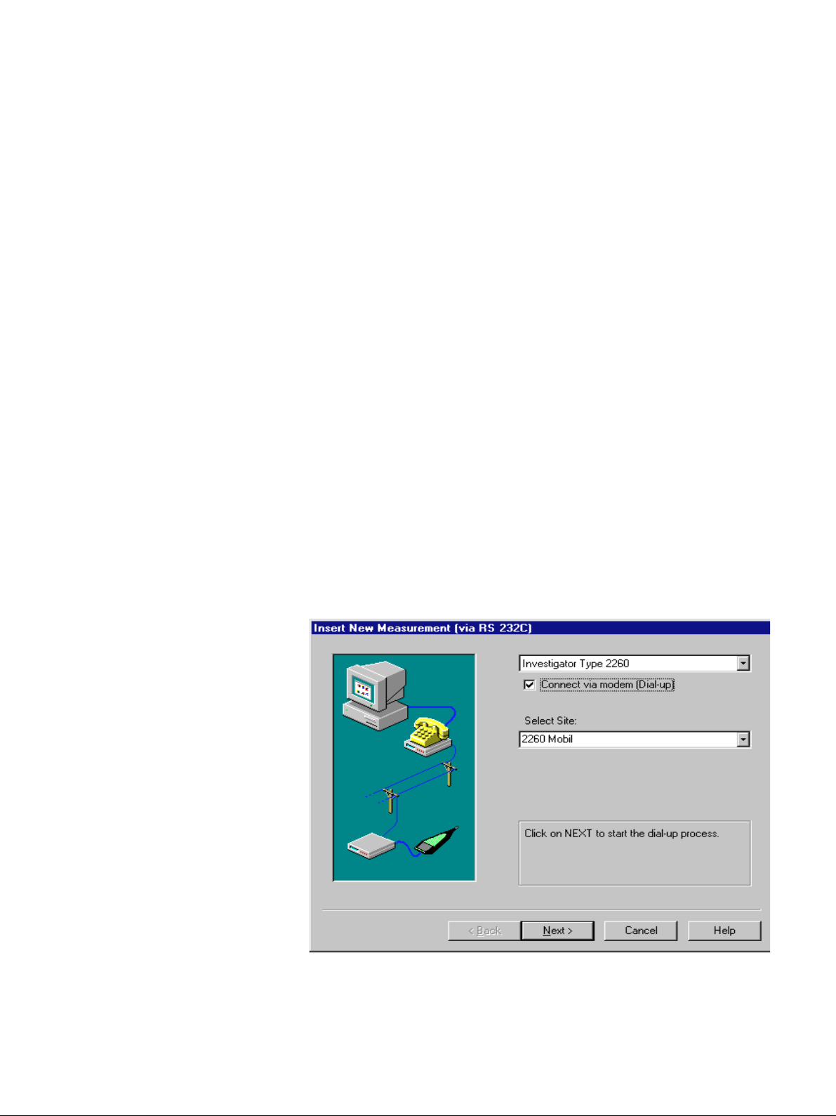
Select the COM-port and Baud Rate. In the INIT command and in the
DIAL command you can insert any string that the so ftware should send
to the modem during initialization and dialing. Start by putting ATZ in
the init command and ATDT in the dial command. If more than one
command is needed for initialization just put <cr> (4 letters) in as
separator, for example:
AT<cr>ATZ<cr>ATM0<cr>
Please consult your modem manual for details on the command param-
eters.
Setting up the Telephone Numbers for Dial-up Sites
Evaluator has a bu ilt-in database f or kee ping phone numbers for remote
sound level meters, that will be contacted by the modem connection.
This database can contain any number of sites.
To define new Dial-up Sites, Choose Options… on the Tool s m enu. Next
select the Dial-up Site s tab. Then click on the New Site… button. Enter
the name of the new site — any characters except \ are allowed in the
site name.
Then enter the telephone numbe r. The Dial prefix box can be use d to
add extra dialing parameters, for example, to get a line outside a local
phone system. If your system requires that you dial, for example, a 0
to get an outside line, then put 0 in the dial prefix box, otherwise leave
this box blank.
Continue this process until all sites have been defined in the database.
Dialling a Remote Site
When your field system has been set up and your home-base modem
has been connected to your PC, you can start downloading measurement data from the field.
This is done the same way that you would capture data from a SLM in
direct connection with a PC, except that you put a ✓ in the box called
Connect via modem (Dial-up). When the ✓ is set in the box, the screen
will change and you will be asked to choose which remote site to dial.
9
Page 10
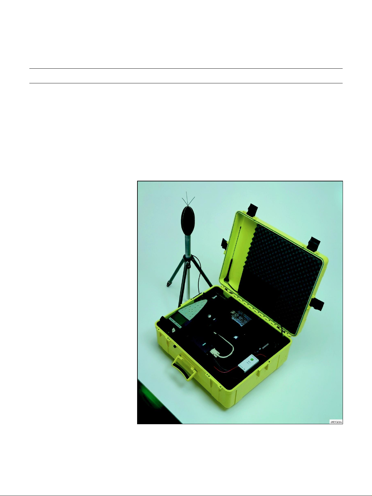
Wireless Modem
Fig.5 Field equipment shown with wireless modem. The antenna must be
placed to the right in the foam insert,
before the lid is closed
Once the PC has connection to the remote site, the rest of the download
process is the same as if the SLM was connected to your PC via the
AO 1386 cable.
Using a GSM dataphone, your field system becomes truly mobile and
wireless — no power line and no phone line is required. There is an
extra team player in the communication chain: the GSM network operator. But once you have got the settings right, it works as smoothly as
the data transfer via norma l telephone lines.
This section shows how to c apture sound measurements from a remote
sound level analyzer (Investigator Type 2260) via GSM transmission in
the field and standard telephone lines and modems at the home-base.
(Precision Integrating Sound Level Meter Type 2236 may also be used).
The field equipment is illustrated in Fig. 5.
10
Field Equipment
Fig. 6 shows the complete system including the home-base modem.
Page 11
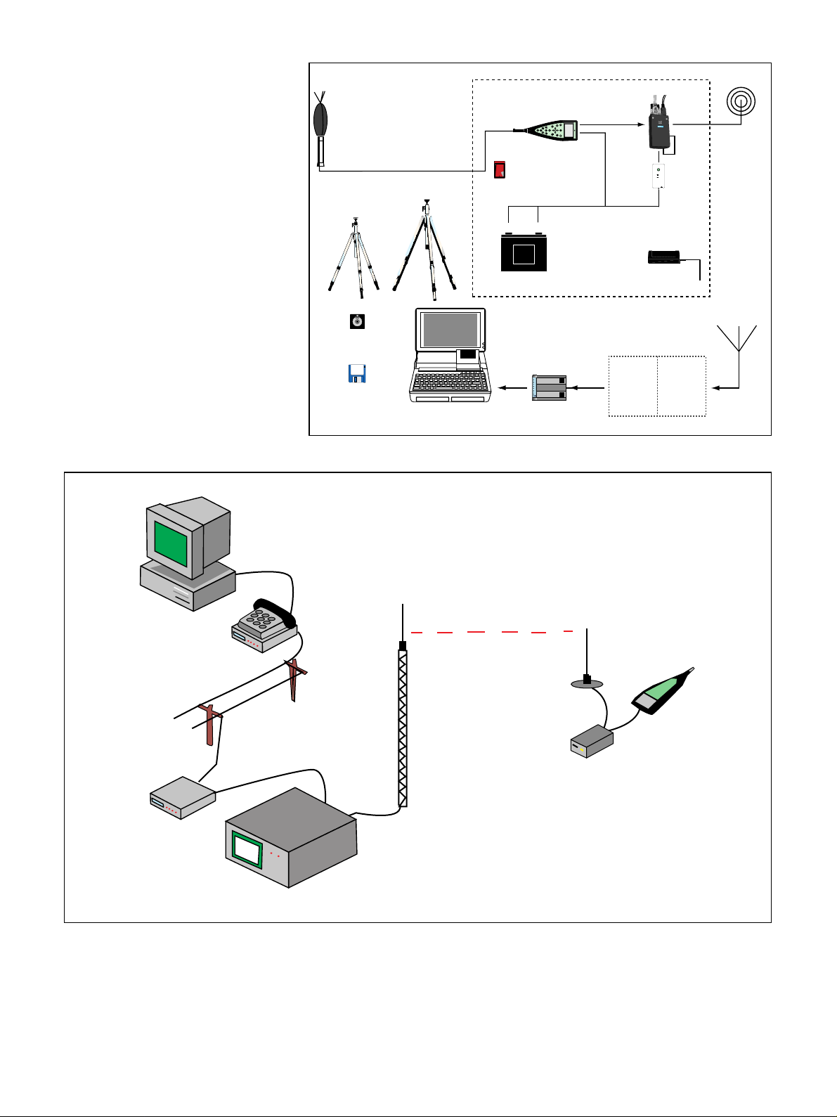
Fig. 6 System dia gram. The d iagram
does not include the optional DAT
record er
Fig. 7 Wi reless mo dem se t-up
Outdoor Microphone Kit UA 1404
(Preamplifier ZG 0026 and
Microphone 4189, from 2260)
Microphone Extension Cable
AO 0441 (3m)
AO 0442 (10m)
Lightweight
Tripod
Tripod
UA 0587
UA 0801
Sound Level
Calibrator 4231
Evaluator 7820
Community noise
calculations
Notebook/PC
Case Type 3592
Sound Level Analyzer
Type 2260
B
M
Enhanced Sound
5
FLASHDISK
MAGS STORAGE
SYSTEM
Sun isk
Analysis Software
BZ 7202
+
—
Panasonic
dflkfpojmmljflkjgjrg
grmowjgfpktjpw
12V Battery
QB 0051
TOSHIBA
Home-base Modem
Hayes
0
dB
?
Brel & Kjr Type 2260
Cable for
12V Supply
¤
compatible
Field Modem
Siemens M1
Modem Hand-
switch ZH 0457
Battery Charger
Telephone
system
Handswitch ZH 0631
Off
On
B
7/6-’89
K
Brel
&Kjr
ZG 0404
network
Card
GSM
SIM
GSM
Antenna
970556e
PC running
Evaluator
Type 7820
Modem at
GSM Operator
Hayes ® Compatible
Modem
Siemens Mobile
Dataphone M1
GSM Net
Operator
2260 Semi-permanent Monitoring Kit
Please refer to the description in the Standard Modem section.
Brüel & Kjær 2236
or 2260
970560e
11
Page 12

Table3 Equipment Equipment Type Available From
PC operating system Windows 95
PC supplier
Windows NT4.0
Windows 3.10 or 3.11
PC-modem cable Depends on modem and PC Modem or PC
supplier
Home-base modem Hayes compatible
e.g. Multitech MT2834ZDX
Modem supplier
or Brüel & Kjær
(ZM 0069)
Field modem Siemens Mobile Dataphone M1Siemens supplier
GSM SIM Card For non-transparent data
Network operator
transfer
Modem Handswitch ZH0457 Brüel &Kjær
Antenna + mounting See section “Antenna” below Mobile-phone
supplier
SLM-Modem cable AO 1440 Brüel & Kjær
SLM 2260 (or 2236) Brüel &Kjær
2260 Semi-permanent
Monitoring Kit
BZ 7202 – 302 (English)
BZ 7202 – 303 (French)
Brüel & Kjær
BZ 7202 – 304 (German)
BZ 7202 Enhanced Sound
Analysis SW
3592 Outdoor Gear
UA1404 Out door Microphon e
Kit
AO 0441 Microphone
Extension Cable (3 m)
QB 0051 12 V Battery
AQ1698 Cable for 12V Supply
ZG 0404 Battery Charger
AQ 1700 Cable for DAT
Remote
AO 0543 DAT Signal Cable
7820 – 002 Evaluator (English)
7820 – 003 Evaluator (French)
7820 –004 Evaluator (German)
12
Lightweight Tripod
Tripo d
UA 0801
UA 0587
Brüel & Kjær
Sound Level Calibr ator 4231 Brüel&Kjær
Page 13
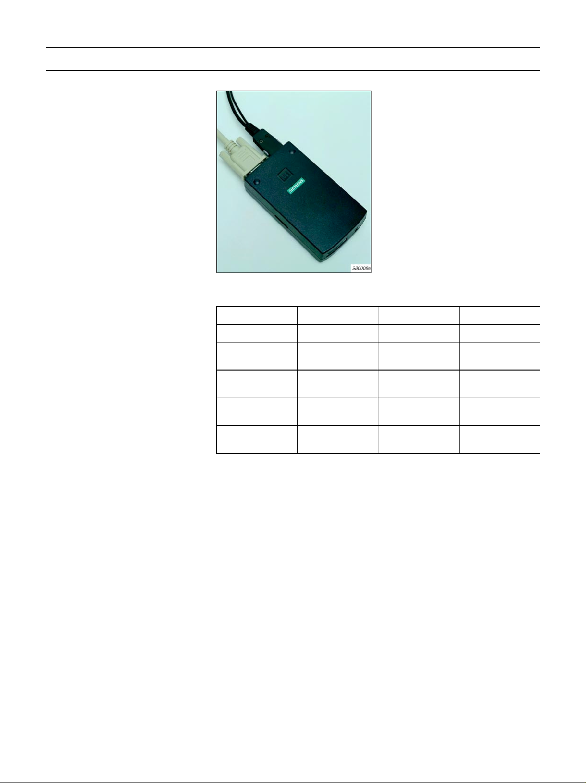
Wireless Modems — Siemens M1 Mobile Dataphone
Fig. 8 Siemens M1 Mobile Dataphone
Table4 Siemens M1 Mobile Data-
phone – manufacturer’s specifications
At the fi eld end we need a device
which is a combination of a mobile phone and a modem. A suit-
able device is the Siemens M1 —
it runs on 12V external DC supply,
and it has a 9–pin RS –232 interface to the built-in modem which
“talks” directly to the built-in GSM
phone unit. It includes a split cable for power supply and antenna
connection .
Currently the maximum transfer
rate of this system is 9600 bits/
sec set by the network operator.
In the future the transfer rate may
increase to 19200 bits/sec (which
the M1 is designed for).
Type M1 Nomin al voltage 13.2 V
Housing Plastic Input current Max. 500 mA
Dimensions 116 x 67 x 30 mm Class of
protection
Weight 157 g Temperature,
operating
III
–20 to +55°C
Memory Flash EPROM Temperature,
storage
Input voltage +8 to +24 V Antenna
impedance
–40 to +70°C
50Ω
Setting up the GSM System
SIM Card
First of all you must have a GSM SIM card in order to get access to the
GSM network. Make sure that this SIM card is set up to work with NONTRANSPARENT DATA TRANSFER by your network operator. Note that
the phone number for data transfer may not be the same as the phone
number normally used with this SIM card. Secondly the SIM card must
not require that a PIN code be entered before use.
Siemens M1
When ordering the Siemens M1, make sure it supports NON-TRANSPARENT data transfer. This means that the M1 firmware must be version
4.02 or later. See APPENDIX 2: Software Update for Siemens M1, for
details.
Next the M1 should be programmed for autoanswer mode. To do this
connect it to your PC on COM-1 or COM-2 and start the Evaluator
software. Choose Options… from the Tools menu. Then select the Modem
tab.
From the modem droplist select User Defined Modem. Set the actual
COM-port where you have connected the M1. Finally set the Baud Rate
to 9600.
13
Page 14
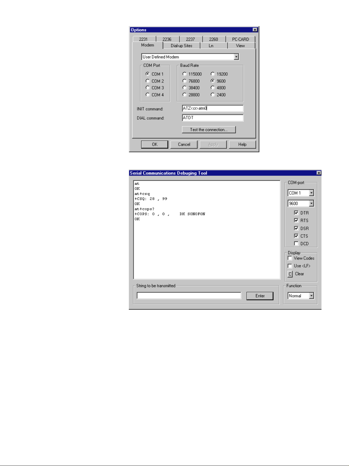
Then click on the Test the connect ion… button.
By entering AT and clicking on the Enter button the M1 should answer
OK.
14
The command AT + CSQ indicates the signal quality (a number between
0 and 31, where 31 is the best).
The co mmand AT+ CO PS? sho ws wheth er you h ave been registered on
the network or not. It should reply with the name of your network
operator.
Now the M1 should be programmed to be in auto-answer mode with a
non-transparent error correction protocol and the result codes should
be disabled.
Enter the commands from Table5 , one by one.
After finishing programming you will notice that the M1 no longer indi-
cates OK to ev ery command, that is because the ATQ1 command has
disabled the output of the results codes. Result codes must be disabled,
otherwise 2260 will try to interpret these messages.
Page 15
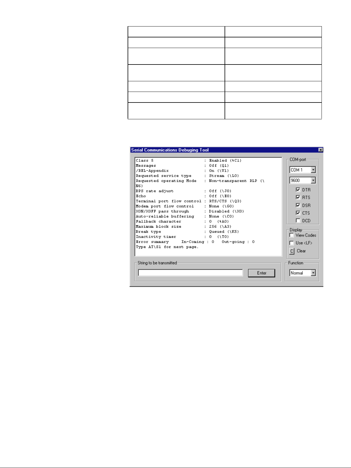
Table5 Siemens M1 programming
commands
Enter Command Significance
ATS0= 1 Answer after 1st ring
AT\N6 Operating mode: Non-Transparent,
ATB98 Operating mode: Autobauding
ATQ1 No Result codes
AT&Y0 Load User Profile 0 at power-up
AT&W0 Write the new configuration to non-
with RLP protocol
Modem, 9600 Baud
volatile memory as User Profile 0
If you the enter AT\S you should get this status screen:
Now you can switch off the M1, position it on the remote site and
connect it to the SLM with an AO 1 440 cable (which is a male/female
9-pin/9-pin RS– 232 cable).
15
Page 16
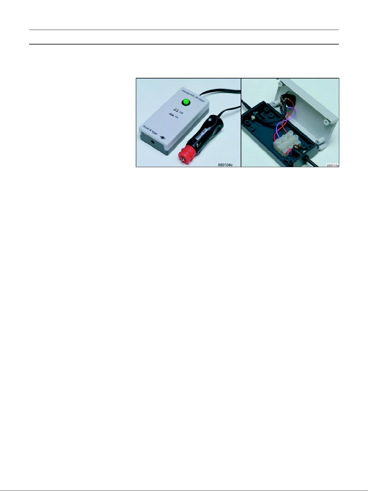
Wireless Modems — Modem Hand-switch ZH0457
The Modem Hand-switch ZH0457 serves to supply power from the 12 V
Battery QB 0051 to the Siemens M1 Mobile Dataphone.
Fig. 9 Modem Hand-switch ZH 0457
The M1 is supplied with a split cable for supply from 12 V power (and
for the antenna). The power supply cable ends in three wires: a red
(+ 12 V), a brown (0 V) and a violet (called “ignition”).
The Modem Hand-switch ZH 0457 provides a connector for the 12 V and
a means of switching t he “ignition” since th is mu st be d on e in th e proper
sequence for the M1 to work.
Connectin g the M1 to the ZH 045 7
1. Open the ZH0457 by removing the four screws at the bottom.
2. Take out the rubber seal and the nylon strap lying inside the ZH0457.
3. Feed the M1 power cable (with the 3 wires) through the rubber seal
(pull the thick end through first).
4. Pu t the 3 wires through the hole in the ZH 0457 base.
5. Screw the red wire into the connector block opposite the red wire
already connected.
6. Screw the violet wire into the connector block opposite the violet
wi re a lrea dy con nec ted .
7. Screw the brown wire into the connector block opposite the brown
wi re a lrea dy con nec ted .
8. Pu t the rubber seal (and the cable) through the hole in the ZH 0457
base.
9. Fasten the rubber seal and cable by mounting and tightening the
nylon strap.
10.Reassemble the ZH 0457 and fasten the four screws.
Connecting the Power Supply to the M1:
The 12 V battery QB 0051 must be in charged condition and equipped
with the 12 V Cable AQ 1698.
1. Connect the ZH0457 to the socket on the AQ 1698.
2. Make sure that the switch on the ZH 0457 is in the Off position.
3. Connect the M1 c able to the M1 Mobile Dataphone.
4. Press the switch on the ZH 0457 to select the On position — the light
in the switch should turn on.
5. The M1 is now powered from the 12 V battery.
6. To remove power from the M1, press the key on the ZH0457 to select
the Off position.
16
Page 17

7. Wait until the green power i ndicator on the M1 stops flashing (i t may
take up to 10 s).
8. N ow the M1 cable or the 12 V connection may be disconnected.
Warni n g : The above sequence should always be followed, otherwise
damage may result to the M1 or the SIM card.
Batter y Life
The M1 will typically consume 70mA when in the standby mode (which
it will be most of the time). During transmission the consumption increases as indicated in the table below.
Assuming consumption of 70 mA and the recommended set-up for the
2260, batttery life for the QB0051 will be reduced by about 20%, corresponding to one day.
Table6 M1 Power Consumption at
12 V – manufac turer’s data
Channel
Search
Typical Max. Typical Max.
130mA 70mA 150mA 220mA 500mA
Standby Send Mode
Antenna
The Siemens M1 Mobile Dataphone must be connected to a suitable
antenna of 50 Ω impedance. Since transmission conditions vary greatly,
it is not possible to predict the field performance of a particular antenna
design or placement. In many cases a simple antenna (the type used in
cars) is sufficient, and the non-conductin g case offers some interesting
mounting features. There are generally two types of simple car antennas:
one for mounting on metal (for example on the roof) and one for mounting on glass (for example a windscreen).
The type fo r mounting on m etal (also known as a ground plane) may be
placed in the foam insert at the position normally occupied by the
tripod. Take care not to place other conductors (cables) close to the
antenna. The non-condu cting case allows transmission of the GSM si gnal. If required, transmission can be improved by placing a ground plane
(conducting metal sheet, at least 50 ×50 cm) under this antenna.
The type for mounting on glass has two self-adhesive units to be fastened
precisely opposite each other on each side of the window (case lid for
our application). The antenna itself is clicked into the outer unit and
can be removed for transport. Fig.10 may help in locating the tw o units
precis el y.
Anten nas desi gned for use i n boa ts are available and may provide better
transmission. They do not need a ground plane.
Checking Transmission in the Field
To check tr ansmi ssion in the fi eld, u se a norm al mob ile pho ne and call
up the M1 (which must be connected to the 2260 and both devices
turned on). Check that the call comes through. If not, and antenna
problems are suspected, try one or a combination of the following:
❍ re-orientate the antenna
❍ move the antenna to a higher position
❍ provide a ground plane for the antenna
17
Page 18
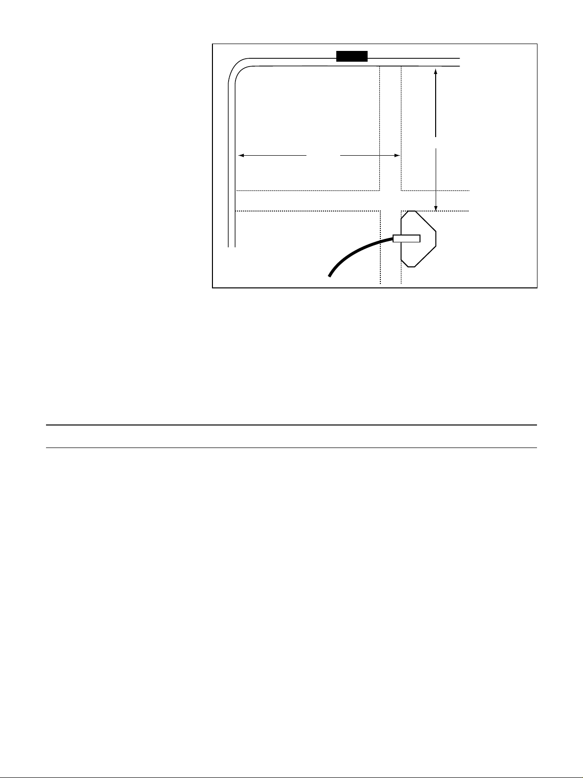
Fig. 10 Template for positioning the
parts for a car antenna (glass-mounti ng
type) on the inside and outside of the
case
Case lid,
internal view
95 mm
105 mm
External brace
Antenna
cable
970559e
The Home-base Modem
The home-base modem should be set up as described in the Standa rd
Modems — Home-base Modem section.
The SLM
The 2236 or the 2260 should be set up as as described in the Setting
up the 2236 for Modem Transfer and Setting up the 2260 for Modem
Transfer sections, except that the baud rate mu st be set to 9600.
APPENDIX 1: Selection of Field Modem
The modem used in the field is critical, because it must be intelligent
enough to provide error correction, but dumb enough not to interpret
any of the communication nor to add anything by sending messages
such as »CONNECT« to the sound level meter.
The requirements for the field modem can be summed up as follows:
❍ Error correction must be supported
❍ The baud rate towards the SLM must be fixed without any relation
to the baudrate used o n the phoneline
❍ Hardwire handshake (RTS/CTS) must be supported
❍ The modem must not interpret any commands
❍ The modem must not send any status messages to the SLM
❍ The DCD line must indicate the actual connection state
❍ The modem must disconnect when the carrier signal disappears
❍ The modem must be able to work over an extended temperature
range
Testing a number of modems in the field, Brüel & Kjær has found the
Multitec h MT2834 ZDX modem to be the best choice, and recommends
that only this modem is used for field use. Brüel &Kjær does not provide
technical support for any other modem.
18
Page 19

APPENDIX 2: Software Update for Siemens M1
When ordering the Siemens M1, make sure it supports NON-TRANSPARENT data transfer. This means that the M1 firmware must be version
4.02 or later. If not, you can get it from Siemens. Also you can get a
description of the new software features (Word file M1-nt2.doc) from
Siemens.
The Siemens instructions to download the new software are the following:
Down loading N ew Softwar e
The M1 consists of two hardware parts, the DSA (Data Service Adapter)
and the Mobile. Because of this the software update consists of two files:
1. DL_0_50N.EXE — software update for the DSA (test version)
2. M 1_4 _02N .EX E — software update for the Mobile
To update the M1 be sure that it is switched on, and that the M1 is
connected with the COM port of the PC. Then execute the two files in
the order mentioned above:
1. If the M1 is connected via the COM2 port enter: DL_0_50N -COM2
to implement the new DSA software.
For help enter: DL_0_50N -H
2. To implement the new M1 software, enter:
Note: The current version of the User Guide and of the M1 software
can be found in the following mailbox:
M1_4_02N -COM2
Mailbox telephone number: +49 89 722 46555.
19
Page 20

HEADQUARTERS: DK-2850 Nærum · Denmark · Telephone: +4545800500 · Fax: +4545801405 · http://www.bk.dk · e-mail: [email protected]
BO0458–1198/0
2
Australia (02)9450-2066 · Austria 0043-1-8657400 · Belgium 016/449225 · Brazil (011)246-8166 · Canada: (514)695-8225
China 1068419625/1068437426 · Czech Republic 02-67021100 · Finland 90-229 3021 · France (01)69906900 · Germany 06103/908-5
Hong Kong 25487486 · Hungary (1)2158305 · Italy (02)57604141 · Japan 03-3779-8671 · Nederland (0)30 6039994
Republic of Korea (02)3473-0605 · Norway 66904410 · Poland (0-22)409392 · Portugal (1)4711453 · Singapore (65) 275-8816
Slovak Republic 073789520 · Spain (91)3681000 · Sweden (08)7112730 · Switzerland 01/9400909 · Taiwan (02)7139303
United Kingdom and Ireland (0181)954-2366 · USA 18003322040 · Local representatives and service organisations worldwide
 Loading...