

BRP Commander 800R Can-Am 2013, Commander 1000 Can-Am 2013 Shop Manual
INTRODUCTION
www.MilitaryAtv.com
INTRODUCTION
This Shop Manual covers the following BRP made
2013 Can-Am side by side vehicles.
MODEL
Commander
800R
Commander
1000
The information and component/system descriptions contained in this manual are correct at time
of writing. BRP however, maintains a policy of
continuous improvement of its products without
imposing upon itself any obligation to install them
on products previously manufactured.
Duetolat
ences bet
descript
BRP reserves the right at any time to discontinue
or change specifications, designs, features, models or equipment without incurring obligation.
ENGINE
TYPE
810
1010
e changes, there may be some differ-
ween the manufactured product and the
ion and/or specifications in this document.
MODEL NUMBER
6CDA, 6CDB, 6CDC, 6TDA,
6DDA, 6DDB, 6
6ADA, 6ADB, 6PDA, 6BDA,
6BDB, 6BDD,
6BDG, 6BDH, 6EDA,
6EDB, 6EDC, 6EDD, 6GDA,
6GDB, 6GDC,
DDC
6BDE, 6BDF,
6GDD
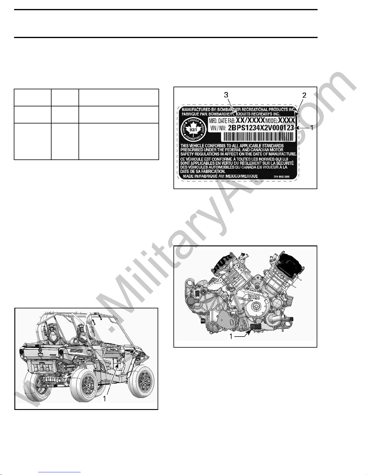
VIN Decal Description
tmr2011-002-005_a
TYPICAL — VEHICLE IDENTIFICATION NUMBER LABEL
1. VIN (Vehic
2. Model number
3. Manufacturing date
le Identification Number)
ENGINE IDENTIFICATION
NUMBER (EIN)
VEHICLE INFORMATION
VEHICLE IDENTIFICATION
NUMBER (VIN)
11-002-001_a
tmr20
TYPICAL
1. VIN (Vehicle Identification Number) location
The VI
cate
N (Vehicle Identification Number) decal is lo-
d under the glove box on the passenger side.
1-002-002_a
tmr201
TYPICAL - RH SIDE OF ENGINE
1. Engine Identification Number (EIN)
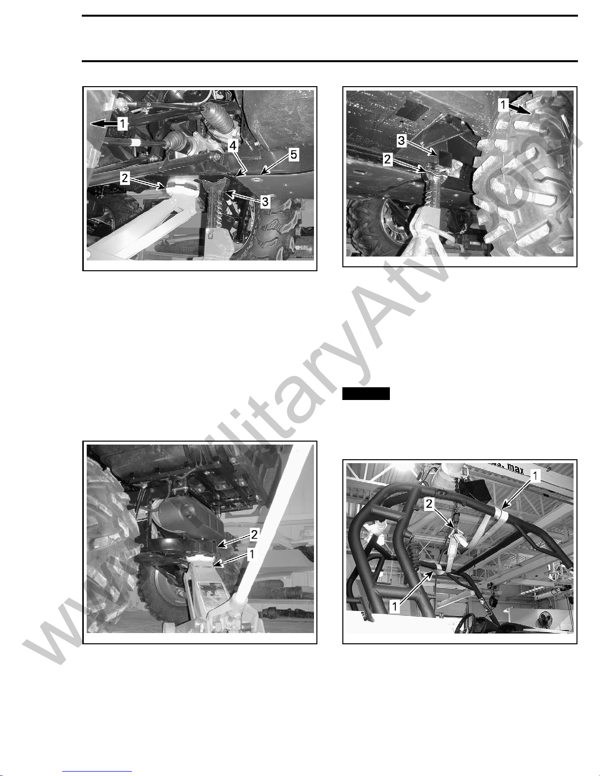
LIFTING AND SUPPORTING THE
VEHICLE
Front
1. Place vehicle on a flat non slippery ground.
2. Ensure vehicle shift lever is set to PARK.
3. Inst
4. Lift front of vehicle and install a jack stand on
of Vehicle
all an hydraulic jack under front skid plate.
each side under frame section in front of the lip
for center skid plate.
X tmr2013-002
INTRODUCTION
www.MilitaryAtv.com
tmo2011-001-315_a
1. Front of vehicle
2. Hydraulic jack
3. Jack stand
4. Lip for center skid plate
5. Center skid plate
5. Lower hydraulic lift and ensure vehicle is supported safely onto both jack stands.
Rear of Vehicle
1. Place vehicle on a flat non slippery ground.
2. Activate 4WD mode.
3. Ensure vehicle shift lever is set to PARK.
4. Install a hydraulic jack under the trailer hitch.
tmo2011-001-316_a
1. Rear of vehicle
2. Jack stand
3. Frame section
6. Lower hydraulic lift and ensure vehicle is supported safely onto both jack stands.
HOISTING THE VEHICLE
The vehicle may be lifted off the ground by the
cage using a hoist and a lifting strap.
NOTICE
around the horizontal side tubes at the top of
the cage, NOT fore and aft. Lifting vehicle by
the fore and aft tubes of the cage can cause
damage.
The lifting strap must be wrapped
2011-001-317_a
tmo
1. Hydraulic jack
2. Trailer hitch
t rear of vehicle and install a jack stand on
5. Lif
h side under frame section in front of rear
eac
eel.
wh
tmr2013-002 XI
tmr2011-002-004_a
1. Lifting strap around horizontal side tubes (top)
2. Hoist hook
INTRODUCTION
www.MilitaryAtv.com
WARNING
– Ensure hoist a
lifting the to
plicable man
– Ensure lifting strap is in good condition be-
fore lifting vehicle.
– Do not allow anyone in the vehicle or under
any portion of the vehicle while it is suspended by a hoist.
– Do not perfo
while it is
nd lifting strap are rated for
tal vehicle weight. Refer to ap-
ufactures instructions.
rm any work on the vehicle
suspended by a hoist.
TRANSPORTING THE VEHICLE
If the vehicle needs to be transported, it should be
carried inside a full size pick-up box or on a flatbed
trailer of the appropriate size and capacity.
NOTICE
seriously damage the vehicle drive system.
When contacting a towing or transporting service,
be sure to ask for tie-down straps, a flatbed trailer,
loading ramp or power ramp to safely lift and secure the vehicle. Ensure the vehicle is properly
transported as specified in this section.
NOTICE
vehicle - they may damage the surface finish
or plastic components.
To load the vehicle for transport, proceed as follows:
1. Set gear shift lever to NEUTRAL (N).
2. Remove the key from the ignition switch.
3. If the vehicle is equipped with a winch, use the
winch to roll the vehicle onto the transport vehicle.
4. If the vehicle is not equipped with a winch, proceed as follows:
4.1 Put a strap around the lower arm of each
4.2 Attach the straps to the winch cable of the
4.3 Pull the vehicle on the flatbed trailers with
.
NOTE: Be sure to leave the gear shift lever in
NEUTRAL (N).
5. Set ACS suspension setting to 1 (softest).
6. Tie down the front wheels to the front of the
trailer using tire towing straps.
Do not tow this vehicle - towing can
Avoid using chains to tie down the
front suspension.
towing vehicle.
the winch.
7. Pass a tie-down strap inside each rear wheel.
8. Firmly attach the rear wheels tie-down straps to
both sides of the rear of the trailer with ratchets.
9. Ensure that both the front and rear wheels are
firmly secured to the trailer.
ENGINE EMISSIONS
INFORMATION
MANUFACTURER'S
RESPONSIBILITY
Manufacturers of engines must determine the
exhaust emission levels for each engine horsepower family and certify these engines with
the United States of America Environmental
Protection Agency (EPA). An emissions control
information label, showing emission levels and
engine specifications, must be placed on each
vehicle at the time of manufacture.
DEALER RESPONSIBILITY
When servicing any vehicle that carry an emissions control information label, adjustments must
be kept within published factory specifications.
Replacement or repair of any emission related
component must be executed in a manner that
maintains emission levels within the prescribed
certification standards.
Dealers are not to modify the engine in any manner that would alter the horsepower or allow emission levels to exceed their predetermined factory
specifications.
Exceptions include manufacturer's prescribed
changes, such as altitude adjustments.
OWNER RESPONSIBILITY
The owner/operator is required to have engine
maintenance performed to maintain emission
levels within prescribed certification standards.
The owner/operator is not to, and should not allow anyone else to modify the engine in any manner that would alter the horsepower or allow emissions levels to exceed their predetermined factory
specifications.
XII tmr2013-002
EPA EMISSION REGULATIONS
www.MilitaryAtv.com
Vehicles manufactured by BRP are certified to the
EPA standards as conforming to the requirements
of the regulations for the control of air pollution
emitted from new vehicle engines. This certification is contingent on certain adjustments being
set to factory standards. For this reason, the
factory procedure for servicing the product must
be strictly followed and, whenever practicable,
returned to the original intent of the design.
The responsibilities listed above are general and
in no way a complete listing of the rules and regulations pertaining to the EPA requirements on exhaust emissions. For more detailed information
on this subject, you may contact the following locations:
FOR ALL COURIER SERVICES:
U.S. Environmental Protection Agency
Office of Transportation and Air Quality
1310 L Street NW
Washington D.C. 20005
REGULARUSPOSTALMAIL:
1200 Pennsylvania Ave. NW
Mail Code 6403J
Washington D.C. 20460
INTERNET: http://www.epa.gov/otaq/
E-MAIL: otaqpublicweb@epa.gov
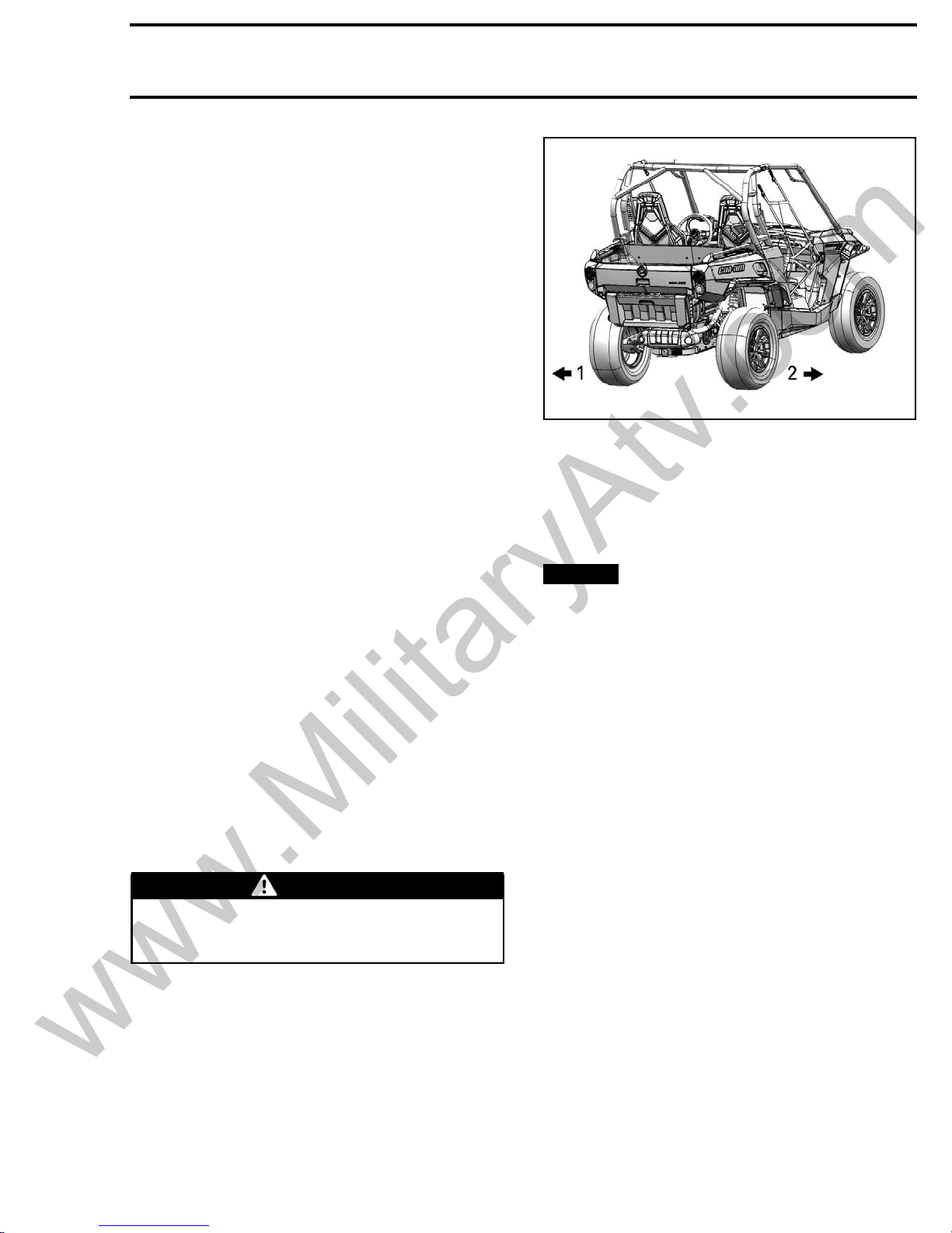
INTRODUCTION
tmr2011-002-003_a
TYPICAL
1. Left
2. Right
This manual uses technical terms which may be
different from the ones of the
When ordering parts always refer to the specific
model
NOTICE
components are built with parts dimensioned
using the metric system. Consult the appropriate
rect parts and fasteners. Mismatched or incorrect fasteners could cause damage to the vehicle.
PART S C ATAL O G S
Most fasteners are metric, and most
PARTS CATALOG
to obtain and use the cor-
PARTS CATALOGS
.
.
MANUAL INFORMATION
MANUAL PROCEDURES
Many of the procedures in this manual are interrelated. Before undertaking any task, you should
read and thoroughly understand the entire section
or subsection in which the procedure is contained.
WARNING
Unless otherwise specified, the engine
should be turned OFF and cold for all maintenance and repair procedures.
A number of procedures throughout the book require the use of special tools. Before starting any
procedure, be sure that you have on hand all required tools, or their approved equivalents.
The use of RIGHT and LEFT indications in the text
are always referenced to the driving position (sitting on the vehicle).
MANUAL LAYOUT
This manual is divided into many major sections as
can be seen in the main table of contents at the
beginning of the manual.
Each section is divided into various subsections,
and again, each subsection has one or more divisions.
Illustrations and photos show the typical construction of various assemblies and, in all cases, may
not reproduce the full detail or exact shape of the
parts used in a particular model vehicle. However,
they represent parts which have the same or a
similar function.
tmr2013-002 XIII
INTRODUCTION
www.MilitaryAtv.com
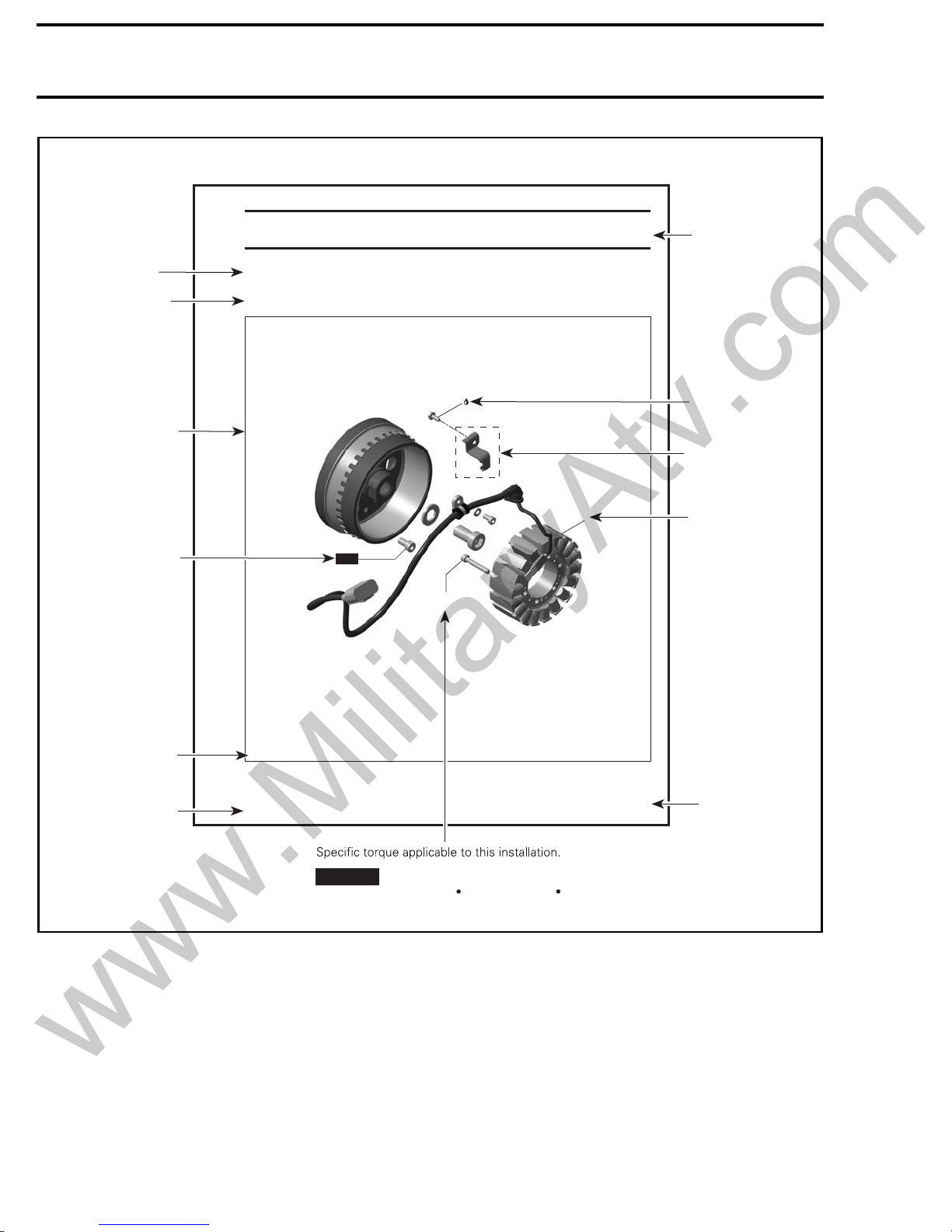
TYPICAL PAGE
Subsection title
Indicates applicable
models.
Exploded view assists
you in identifying parts
and their related
positions.
NEW indicates that the
part must be replaced
with a new one.
MAGNETO
Models
NEW
Loctite 243
5 Nm
(44 lbfin)
Section 06 ENGINE
Subsection 01 (MAGNETO)
Model
Page heading
indicates section
and subsection.
Drop represents a
service product
to be applied.
Dotted box contains
parts applicable to a
specific model.
Bold face number
1
is used to identify
a part referred to
the text.
Illustration number
for publishing process.
Document number for
publishing process.
Typical_iso_2008_en
XXX0000
mmr2008-001
Pay attention to torque specifications.
NOTICE
Some of these are in lbf in instead of lbf ft.
Use appropriate torque wrench.
55
Page number
XIV tmr2013-002
 Loading...