

BRP 5006181, 5006180 Installation Instructions Manual
PREWIRED SURFACE MOUNT REMOTE CONTROL
INSTALLATION INSTRUCTIONS
APPLICATION
This surface mount remote control assembly is
designed for use on Evinrude
outboards.
SAFETY INFORMATION
For safety reasons, this kit should be installed by
an authorized Evinrude®/ Johnson® dealer. This
instruction sheet is not a substitute for work experience. Additional helpful information may be found
in other service literature for your engine.
This instruction sheet uses the following signal
words identifying important safety messages.
DANGER
Indicates an imminently hazardous situation which, if not avoided, WILL result in
death or serious injury.
WARNING
Indicates a potentially hazardous situation
which, if not avoided, CAN result in severe
injury or death.
CAUTION
Indicates a potentially hazardous situation
which, if not avoided, MAY result in minor
or moderate personal injury or property
damage. It also may be used to alert
against unsafe practices.
IMPORTANT: Identifies information that will
help prevent damage to machinery and appears
next to information that controls correct assembly and operation of the product.
These safety alert signal words mean:
®
and Johnson
Always follow common shop safety practices. If
you have not had training related to common
shop safety practices, you should do so to pro-
®
tect yourself, as well as the people around you.
It is understood that this instruction sheet may be
translated into other languages. In the event of any
discrepancy, the English version shall prevail.
DO NOT do any repairs until you have read the instructions and checked the pictures relating to the
repairs.
Be careful, and never rush or guess a service procedure. Human error is caused by many factors:
carelessness, fatigue, overload, preoccupation,
unfamiliarity with the product, and drugs and alcohol use, to name a few. Damage to a boat and outboard can be fixed in a short period of time, but
injury or death has a lasting effect.
When replacement parts are required, use
Evinrude/Johnson Genuine Parts or parts with
equivalent characteristics, including type, strength
and material. Using substandard parts could result
in injury or product malfunction.
Torque wrench tightening specifications must be
strictly followed. Replace any locking fastener
(locknut or patch screw) if its locking feature becomes weak. Definite resistance to turning must be
felt when reusing a locking fastener. If replacement
is specified or required because the locking fastener has become weak, use only authorized
Evinrude/Johnson Genuine Parts.
If you use procedures or service tools that are not
recommended in this instruction sheet, YOU
ALONE must decide if your actions might injure
people or damage the outboard.
TO THE INSTALLER: Give this sheet to the owner.
Advise the owner of any special operation or maintenance information contained in the instructions.
TO THE OWNER: Save these instructions in your
owner’s kit. This sheet contains information important to the future use and maintenance of your outboard.
ATTENTION!
BECOME ALERT!
YOUR SAFETY IS INVOLVED!
Printed in the Japan.
© 2005 BRP US Inc. All rights reserved.
TM, ® Trademarks and registered trademarks of Bombardier Recreational Products Inc. or its affiliates.
DSS04098 I 1 of 24
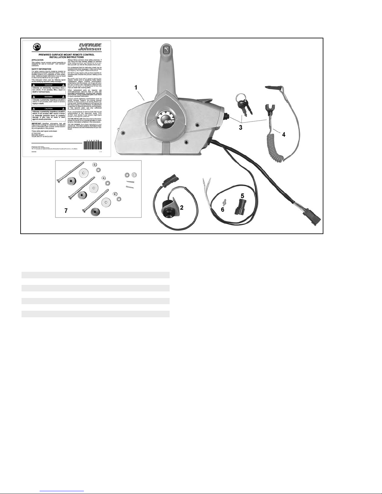
CONTENTS OF KIT
y
,
y
,
,
Ref P/N Name of Part Qt
5006180 REMOTE CONTROL w/ TRIM SW
*
5006181 REMOTE CONTROL
*
1 NA *REMOTE CONTROL AY 1
2 176360 *HORN 1
3 175974 *SWITCH
4 176288 **LANYARD Ass
5 514696 *CONNECTOR
6 514697 *LOCK WEDGE
5006550 *MOUNTING BOLT & SPACER KIT
7
KEY & LANYARD 1
.1
3-Pin 1
3-Pin connector 1
004865
1
2 of 24
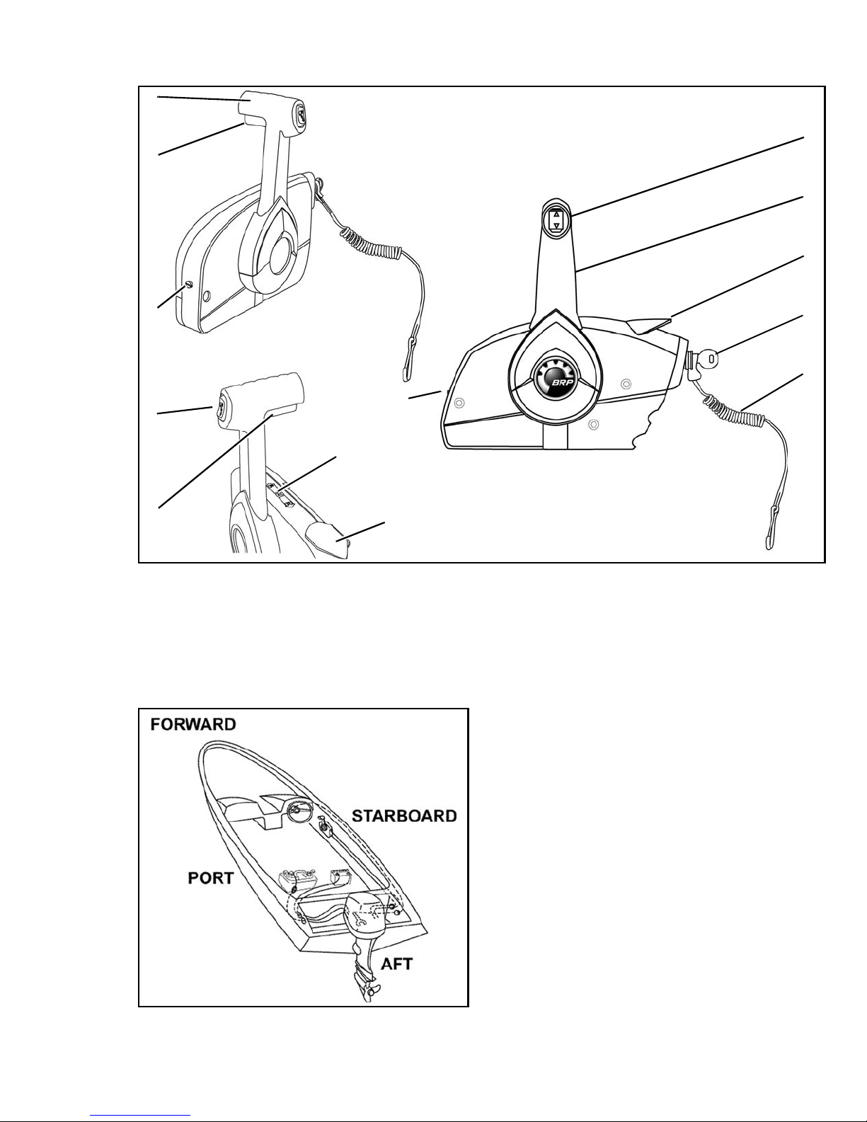
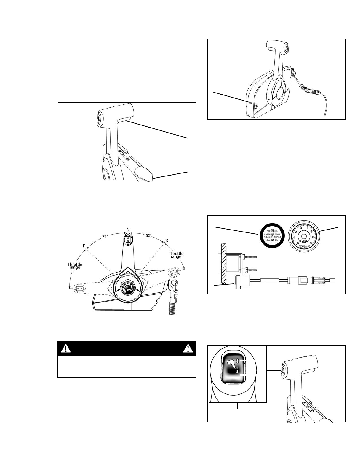
REMOTE CONTROL FEATURES
9
7
1
2
3
6
1
8
7
1. Trim and tilt switch
2. Remote control lever
3. Fast idle lever
4. Emergency stop / key switch
5. Clip and lanyard assembly
6. Adjusting screw, remote control lever friction
7. Neutral lock lever
8. Shift position label
9. Handle, shift and throttle
4
5
6
3
004849
List of Features
• Neutral Lock
Nautical Orientation
• “Start in gear prevention” switch
• Warning horn included
• Adjustable throttle friction
• Pigtail wiring harness – correct ignition wiring harness must be ordered separately
• Uses standard Evinrude / Johnson control
cables (1979 and newer type)
004861
3 of 24
REMOTE CONTROL OPERATION
Fast Idle Lever
Read and familiarize yourself with the complete
operation of the remote control before attempting
to start the outboard.
IMPORTANT: The operation of this remote control may vary from one outboard model to another. Refer to outboard’s operator’s guide for
specific instructions related to outboard.
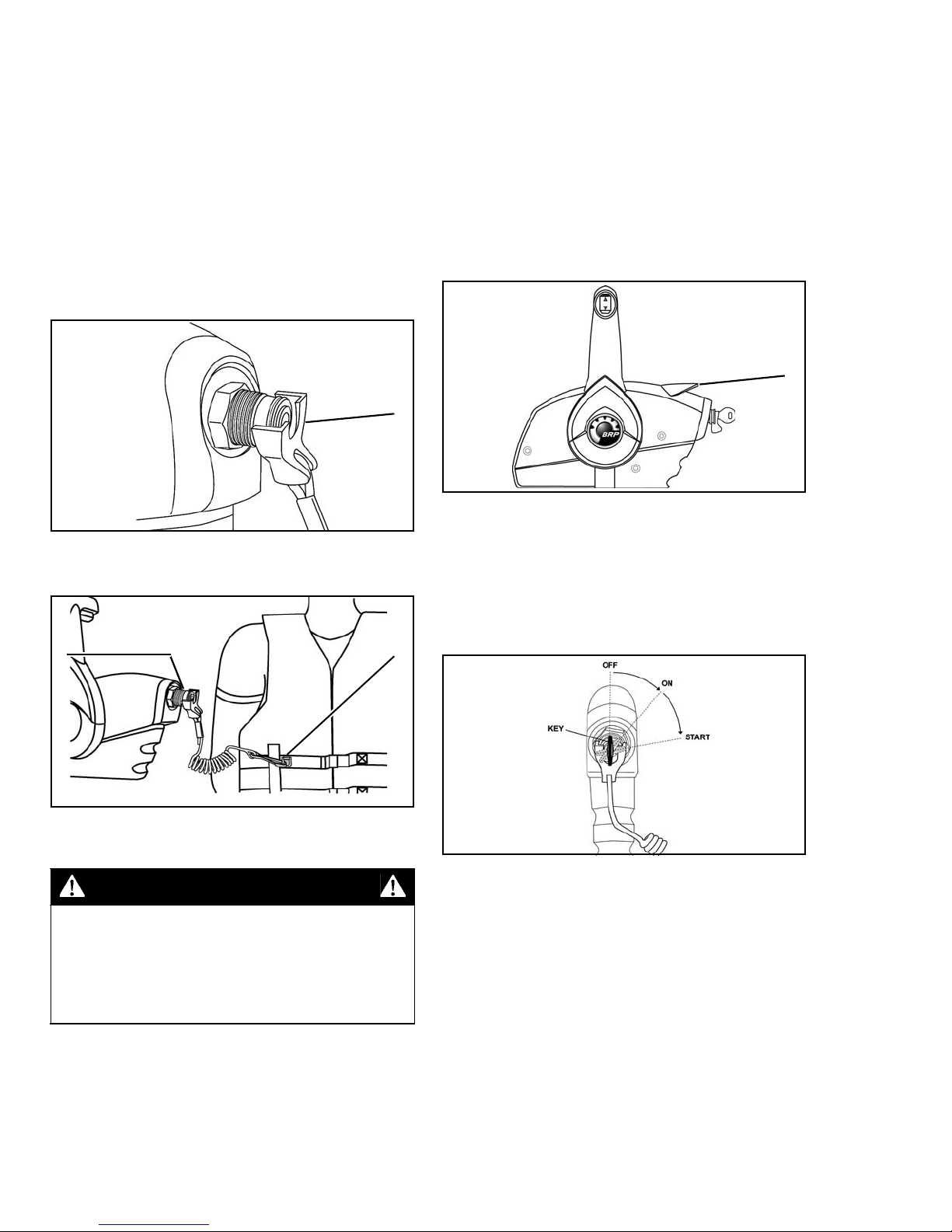
Emergency Stop Feature of Key Switch
Push clip of emergency stop lanyard onto key
switch as shown.
1
1. Emergency stop clip
004848
Use of the fast idle lever is not required on all
models. Refer to operator’s guide for outboard.
The fast idle lever can be used to open throttle
without shifting into gear. With control handle in
NEUTRAL, lift fast idle lever to open throttle for
starting and warm-up. The control is locked in
NEUTRAL when fast idle lever is raised to
prevent shifting into gear at higher than IDLE
RPM. The control handle is unlocked when fast
idle lever is all the way down.
1
1. Fast idle lever
Key Switch
004851
Lanyard MUST be securely attached to operator.
21
1. Key switch
2. Lanyard
004850
WARNING
Lanyard MUST be securely attached to
operator, and clip MUST be installed on
key switch. DO NOT operate outboard with
clip removed from switch, except in an
emergency.
If operator is thrown from helm, lanyard will pull
clip from key switch to stop outboard.
IMPORTANT: In an emergency, a passenger
can put control handle in NEUTRAL and restart
outboard without lanyard.
Turn key switch from OFF to ON position. The
warning horn should sound momentarily to
indicate it is working. Turn key to START
position. To use PRIME feature, push and hold
key IN and turn switch to START position.
004852
Release key as soon as motor starts. DO NOT
turn key to START while outboard is running.
Push key IN momentarily (in ON position) for
additional enrichment (PRIME) to keep outboard
running. Not used on all models.
DO NOT run a cold outboard any faster than
necessary to keep it from stalling. DO NOT
exceed 2500 RPM in NEUTRAL. If raised for
starting, push fast idle lever part way down as
soon as outboard starts. For outboards with
Quikstart™, wait until engine slows to IDLE RPM
before shifting into gear. Refer to operator’s guide
for specific instructions related to outboard.
4 of 24
Control Handle
IMPORTANT: Outboard must be OFF. If remote
control cables are connected to outboard, turn
propeller shaft while shifting remote control.
With control handle in NEUTRAL and fast idle
lever DOWN, lift the neutral lock lever, and move
control handle to FORWARD gear or REVERSE
gear position. Release neutral lock lever and
continue movement of control handle in same
direction to open (advance) throttle.
Turn adjustment screw clockwise to increase the
friction or counterclockwise to reduce the friction.
1
3
1
2
1. NEUTRAL
2. Fast idle lever
3. Neutral lock lever
Refer to Remote Control Configuration for
remote control handle set-up.
004853
1. Adjustment screw, throttle friction
004856
Warning Horn
The warning horn sounds to alert operator when
certain engine problems occur. A 1/2-second
self-test beep should sound when the key switch
is turned ON.
IMPORTANT: The warning horn must connect
to wiring harness with a SystemCheck™ gauge
or an audible horn driver module to be functional.
Refer to Operator’s Guide and instrumentation
instructions for additional information related to
the outboard’s warning system.
32
1
Remote Control Handle Positions
Control Lever Friction Adjustment
WARNING
DO NOT adjust control lever friction
adjustment screw with outboard running.
Move the control lever to FORWARD throttle
range. Control lever should move freely. Adjust
control lever friction adjustment to prevent
vibration from changing throttle setting.
Use a flat head screwdriver to adjust control
lever friction adjustment screw. This adjustment
is used to increase or reduce the force required
to move the control lever.
004854
1. Warning horn
2. 2 in. SystemCheck gauge
3. 3 in. Tachometer / SystemCheck gauge
004857
Trim/Tilt Switch
Push top of switch to trim out and tilt up, or push
bottom of switch to trim in and tilt down.
2
3
1
1. Trim/Tilt switch
2. Top – Trim out / tilt up
3. Bottom – Trim in / tilt down
004853
004860
5 of 24
INSTALLATION INSTRUCTIONS
Read and familiarize yourself with the complete
installation instructions of the remote control
before attempting to install the remote control.
Always test operation of remote control once
installed.
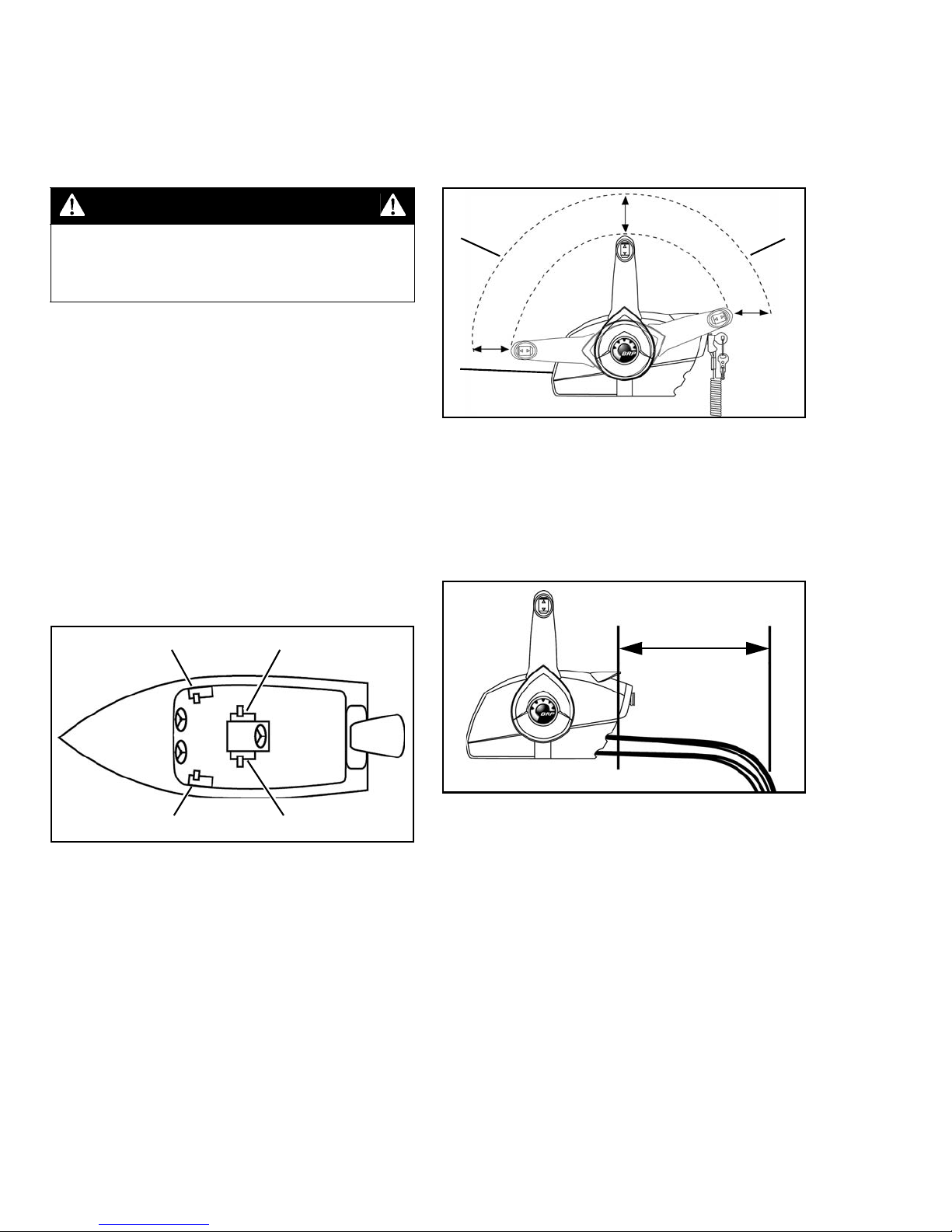
WARNING
Place remote control at proposed location and
check clearance around remote control handle at
full throttle in FORWARD and then at full throttle
in REVERSE. There must be at least 4 in. (10
cm) of clearance between the handle and any
part of the boat throughout the control handle
travel.
Failure to properly install and test remote
control may result in remote control malfunction and loss of control of boat.
IMPORTANT: Refer to specific outboard instal-
lation instructions for information related to connecting remote controls to outboard.
Select Mounting Location
This remote control can be mounted on the
starboard side of the boat, or port side of center
console. In the “starboard side mount” position,
the starboard side of the control is next to the
boat mounting surface.
The control can be mounted on the port side of
the boat, or starboard side of center console if
the control handle is relocated to the opposite
side on control. In the “port side mount”
position, the port side of the control is next to the
boat mounting surface.
12
22
1
1. Remote control
2. 4 in. (10 cm) clearance line
There must be at least 12 in. (30.5 cm) of clear
space behind the remote control for cable
routing. Control cables must be straight as they
exit the remote control. Allow at least 6 in. (15.2
cm) to the beginning of the first bend of control
cables.
004858
12 in.
21
1. Starboard side mount
2. Port side mount
Refer to Remote Control Configuration.
IMPORTANT: Remote control MUST be mount-
ed where the key switch is readily accessible. Also, the mounting location must be a flat surface
and must be strong enough to provide a rigid
support. Strengthen mounting surface as necessary.
6 of 24
004855
1. 12 in. (30.5 cm) clear space
004859
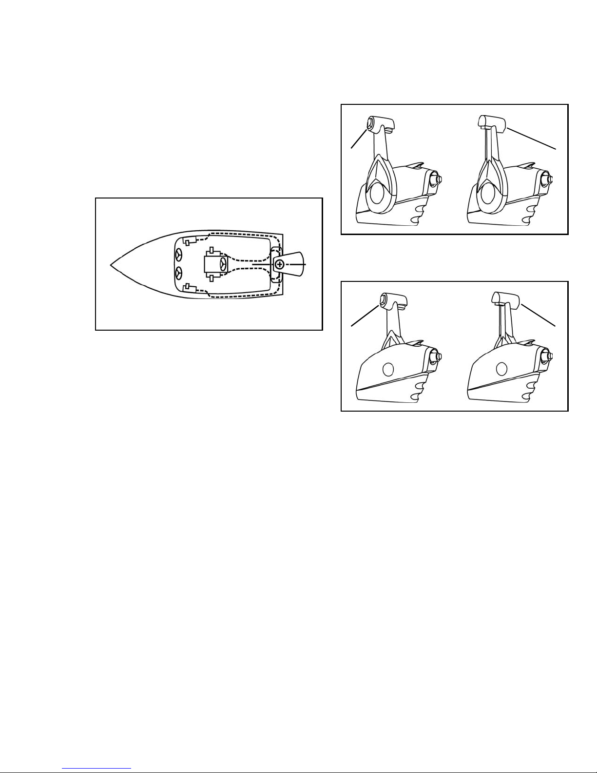
Determine Cable Length
Remote Control Configuration
Measure from center of control handle with
remote control in mounting position, along
intended cable route to engine centerline at
transom height as illustrated by dotted lines in
diagram. Add 40 in. (1.0 m) to the measurement.
This dimension is the required cable length.
Evinrude/Johnson Genuine Parts outboard con-
trol cables are available in one-foot increments
from 5 ft. to 20 ft. lengths and two-foot increments from 20 ft. to 50 ft. lengths. Use cables
that are equal to your calculated length, or are
the next longer available length.
004884
The remote control lever can be positioned on
either side of remote control, and the trim/tilt
switch can be oriented to face the port or
starboard side of remote control.
21
Starboard Side Mount
1. Port side trim/tilt switch (standard configuration)
2. Starboard side trim/tilt switch
004862
21
IMPORTANT: Route cables with fewest number
of bends. Bends must never be less than 6 in.
(15 cm) radius.
Port Side Mount
1. Port side trim/tilt switch
2. Starboard side trim/tilt switch
004863
IMPORTANT: Determine the required control
handle orientation prior to installing remote control cables.
7 of 24
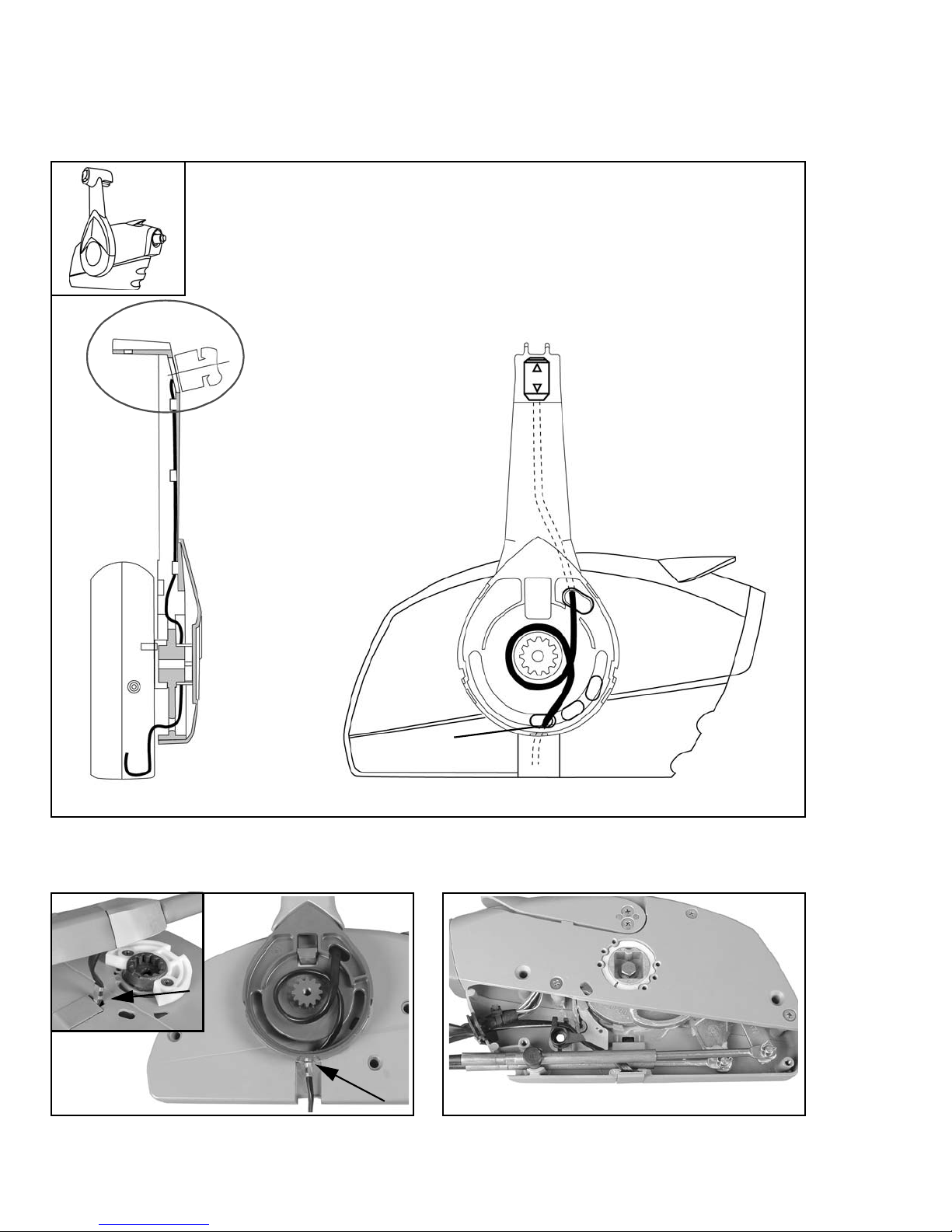
Remote Control Configuration Diagrams
IMPORTANT: Refer to the following diagrams for proper trim/tilt switch wire routing. Route the trim/
tilt wiring through the correct hole in control housing to allow proper movement of lever and to prevent
trim/tilt switch wire damage.
Starboard Mount w/Port Side Trim/Tilt Switch
(Standard/Original Configuration)
2
1. Port side view of remote control
2. Forward view of remote control
3. Shield
Shield
8 of 24
004916
004919
3
1
004882
004918
 Loading...