

Page 1
Page 2
CALIFORNIA PROPOSITION 65 WARNING
WARNING
This product contains or emits chemicals known to the state of California to
cause cancer and birth defects or other reproductive harm.
In Canada, products are distributed by Bombardier Recrea
tional Products Inc.
In USA, products are distributed by BRP US Inc.
This is a non-exhaustive list of trademarks that are the property of Bombardier
Recreational Products Inc. or its affiliates:
4-TEC
TM
Rotax
®
iPhone, iPod, iPod nano and iPod touch ar
Spyder
e trademarks of Apple Inc. registered in
TM
XPS
TM
U.S.A. and other countries.
“Made for iPod” and “Made for iPhone” mea
n that an electronic accessory has
been designed to connect specifically to iPod or iPhone, respectively, and has
been certified by the developer to meet Apple performance standards. Apple
is not responsible for the operati
on of this device or its compliance with safety
and regulatory standards. Please note that the use of this accessory with iPod or
iPhone may affect wireless performance.
rmo2013-005 en
®™ and the BRP logo are trademarks of Bombardier Recreational Products Inc. or its affiliates.
©2012 Bombardi
er Recreational Products Inc. and BRP US Inc. All rights reserved.
Page 3

FOREWORD
Congratulations on your purchase of a new CAN-AM™ Roadster. It is backed
by the Bombardier Recreational Products Inc. (BRP) warranty and a network of
authorized dealers ready to provide the parts, service or accessories you may
require.
Your dealer is committed to your satisfaction. He has taken training to perform the
initial set-up and inspection of your roadster before you took possession.
At delivery, you were informed of the warranty coverage and signed the
LIVERY CHECK LIST
isfaction.
Dieses Handbuch ist möglicherweise in Ihrer Landessprache
Deutsch
English
Español
Français
Nederlands
Norsk
Português
verfügbar. Bitte wenden Sie sich an Ihren Händler oder besuchen Sie:
www.operatorsguide.brp.com.
This guide may be available in your language. Check with your dealer or
go to: www.operatorsguide.brp.com.
Es posible que este manual esté disponible en su idioma. Consulte a su
distribuidor o visite: www.operatorsguide.brp.com.
Ce guide peut être disponible dans votre langue. Vérifier avec votre
concessionaire ou aller à: www.operatorsguide.brp.com.
Deze handleiding kan beschikbaar zijn in uw taal. Vraag het aan uw dealer
of ga naar: www.operatorsguide.brp.com.
Denne boken kan finnes tilgjengelig på ditt eget språk. Kontakt din
forhandler eller gå til: www.operatorsguide.brp.com.
Este manual pode estar disponível em seu idioma. Fale com sua
concessionária ou visite o site: www.operatorsguide.brp.com.
to ensure your new vehicle was prepared to your entire sat-
PREDE-
Suomi
Svenska
Käyttöohjekirja voi olla saatavissa omalla kielelläsi. Tarkistajälleenmyyjältä
tai käy osoitteessa: www.operatorsguide.brp.com
Denna bok kan finnas tillgänglig på ditt språk. Ko
eller gå till: www.operatorsguide.brp.com.
Know Before you Go
For your safety and the safety of passengers and bystanders, read the following sections before you operate
the Spyder roadster:
–
GENERAL PRECAUTIONS
–
VEHICLE INFORMATION
–
SAFE OPERATING INSTRUCTIONS
–
PRE-RIDE INSPECTION
Experienced motorcyclists should pay
special attention to
WHAT'S D
ENT ABOUT THE SPYDER ROADSTER
subsection.
.
IFFER-
ntakta din återförsäljare
Safety Messages
The types of safety messages, what
they look like and how they are used in
this guide are explained as follows:
The safety alert symbol
a potential injury hazard.
indicates
WARNING
Indicates a potential hazard, if not
avoided, could result in serious injury or death.
_______________
1
Page 4

FOREWORD
CAUTION Indicates a hazard
situation which, if not avoided,
could result in minor or moderate
injury.
NOTICE
which, if not followed, could severely damage vehicle components
or other property.
Indicates an instruction
About this Operator's
Guide
This Operator's Guide was written in
North America in a right-lane driving
environment. Please adapt your application of these maneuvers to your
jurisdiction and rules of the road.
In this Operator's Guide, the word
motorcycle typically refers to a
two-wheeled motorcycle.
Keep this Operator's Guide in the front
storage compartment so that you can
refer to it for things such as maintenance, roadside repairs and instructing
others.
If you want to view and/or print an extra copy of your Operator's Guide, simply visit the following website www.
operatorsguide.brp.com.
The informations contained in this document are correct at the time of publication. BRP, however, maintains a policy of continuous improvement of its
products without imposing upon itself
any obligation to install them on products previously manufactured. Due
to late changes, some differences between the manufactured product and
the descriptions and/or specificatio
in this guide may occur. BRP reserves
the right at any time to discontinue or
change specifications, designs, fe
tures, models or equipment without
incurring any obligation upon itself.
ns
a-
Refer to Other Sources of
Information
In addition to reading this Operator's
Guide, you should read the Safety Card
on the vehicle and watch the
DVD
video.
If possible, take a training course
that is specifically designed for the
Spyder roadster. Check our website
at www.can-am.brp.com for more
information about upcoming training
course availability. If you cannot take
a training course specifically designed
for the Spyder roadster, it is a good idea
to take a motorcycle training course,
since some of the skills required are
similar and information about managing risk on the road is taught and
similarly applies to riding your Spyder
roadster.
SAFETY
Acknowledgment
BRP wishes to thank the Motorcycle
Safety Foundation (MSF) for giving
permission to BRP to use their material related to street motorcycle safety
found in this Operator's Guide.
The MSF is an internationally recognized not for profit foundation and
is supported by motorcycle manufacturers. It provides training, tools
and partnerships to the motorcycle
safety community. Visit its website at
www.msf-usa.org.
This Operator's Guide and the
DVD
hicle when it is sold.
2
video should remain with the ve-
_______________
SAFETY
Page 5

TABLE OF CONTENTS
FOREWORD .......................................................................... 1
KnowBeforeyouGo............................................................. 1
SafetyMessages................................................................. 1
AboutthisOperator's Guide .................................................... 2
Referto OtherSourcesofInformation ......................................... 2
Acknowledgment................................................................ 2
GENERALPRECAUTIONS.......................................................... 8
AvoidCarbonMonoxidePoisoning............................................. 8
AvoidGasolineFiresandOtherHazards ....................................... 8
AvoidBurnsfromHot Parts ..................................................... 8
Accessories andModifications ................................................. 8
VEHICLE INFORMATION
PRIMARYCONTROLS ............................................................. 10
1)Handlebar..................................................................... 12
2)Throttle........................................................................ 12
3)ClutchLever(SM5Model)................................................... 12
4)GearshiftLever(SM5Model)................................................ 13
5)GearshiftSelector(SE5Model) ............................................. 13
6)BrakePedal ................................................................... 14
7)ParkingBrakeSwitch ........................................................ 14
SECONDARYCONTROLS......................................................... 16
1)IgnitionSwitch................................................................ 16
2)EngineStartButton .......................................................... 17
3)EngineStopSwitch .......................................................... 17
4)HazardWarningSwitch...................................................... 17
5)CruiseControlSwitch........................................................ 18
6)HeadlightSwitch ............................................................. 20
7)TurnSignalButton............................................................ 21
8)HornButton................................................................... 21
9)WindshieldAdjustmentButton ............................................. 21
10)RECC (RoadsterElectronicCommand Center)........................... 22
11)Reverse Button ............................................................. 22
12)PTT(PushToTalk)Button .................................................. 23
13)SwitchCluster............................................................... 23
PASSENGERCONTROLS ......................................................... 26
PassengerHeatedGripSwitch ................................................ 26
PassengerAudioControls ..................................................... 26
MULTIFUNCTIONGAUGE ........................................................ 27
MultifunctionGauge Description.............................................. 27
1)AnalogSpeedometer ........................................................ 27
2)AnalogTachometer (RPM)................................................... 27
3)IndicatorLamps .............................................................. 27
4)DigitalDisplay................................................................. 32
MultifunctionGauge Startup Information..................................... 32
_______________
3
Page 6

TABLE OF CONTENTS
MULTIFUNCTION GAUGE (cont’d)
DigitalDisplayDescription ..................................................... 32
NavigatingintheDigitalDisplay................................................ 34
CategoryIconScreenDescription............................................. 35
ANALOGGAUGES(OPTIONPACKAGE)........................................ 39
FuelLevelGauge................................................................ 39
EngineCoolantTemperatureGauge........................................... 39
AUDIOCONTROLS................................................................. 40
AudioSystemPower ........................................................... 40
AudioVolumeControl........................................................... 40
Self-Adjusting AudioVolume................................................... 40
AudioMute ...................................................................... 40
RadioBand....................................................................... 40
AUX (Auxiliary)................................................................... 41
CBScreen(Optional)............................................................ 42
GPS(OPTIONPACKAGE).......................................................... 43
GPSReceiverInstallation....................................................... 43
GPSReceiverRemoval......................................................... 43
EQUIPMENT......................................................................... 44
Mirrors ........................................................................... 44
GloveBox........................................................................ 44
FrontStorageCompartment................................................... 45
Seat .............................................................................. 45
StorageCompartments ........................................................ 46
Helmet........................................................................... 48
ToolKit ........................................................................... 48
Operator'sGuide................................................................ 48
BodyPanels ..................................................................... 49
BASICPROCEDURES.............................................................. 54
AdjustingthePassengerFootrest ............................................. 54
StartingandStoppingtheEngine.............................................. 54
OperatinginReverse ........................................................... 56
OperationDuringBreak-In...................................................... 56
Fueling ........................................................................... 57
AdjustingSuspension........................................................... 58
Usingthe12VPowerOutlet................................................... 59
SAFE OPERATING INSTRUCTIONS
WHAT'SDIFFERENT ABOUTTHESPYDERROADSTER...................... 62
Stability .......................................................................... 62
Response toRoadConditions.................................................. 62
BrakePedal...................................................................... 62
ParkingBrake.................................................................... 62
Steering.......................................................................... 62
Width............................................................................. 63
_______________
4
Page 7

TABLE OF CONTENTS
WHAT'S DIFFERENT ABOUT THE SPYDER ROADSTER (cont’d)
Reverse.......................................................................... 63
Driver'sLicenseandLocalLaws............................................... 63
DRIVINGAIDTECHNOLOGIES................................................... 64
Vehicle Stability System (VSS) ................................................. 64
DynamicPowerSteering(DPS)................................................ 65
UNDERSTANDINGRISKONTHE ROAD ........................................ 66
TypeofVehicle .................................................................. 66
Operator Skills and Judgment.................................................. 66
RiderCondition.................................................................. 66
VehicleCondition................................................................ 67
RoadandWeatherConditions ................................................. 67
RIDINGGEAR ....................................................................... 68
Helmets.......................................................................... 68
OtherRidingGear............................................................... 68
REQUIREDRIDINGSKILLSANDPRACTICEEXERCISES..................... 71
Choosing aPractice Area....................................................... 71
PreparingtoRide................................................................ 72
RidingPosture................................................................... 72
PracticeExercises(SM5Model)............................................... 72
PracticeExercises(SE5Model)................................................ 81
Developing Advanced Riding Skills ............................................ 88
STREETSTRATEGIES.............................................................. 89
PlanyourTrip .................................................................... 89
DefensiveRiding................................................................ 89
BeingVisible..................................................................... 90
LanePosition .................................................................... 91
CommonRidingSituations..................................................... 91
RoadConditionsandHazards.................................................. 94
On-RoadEmergencies ......................................................... 95
TireFailure ....................................................................... 95
CARRYINGAPASSENGER,CARGOORTOWINGATRAILER............... 97
WeightLimits.................................................................... 97
OperatingwithExtraWeight................................................... 97
CarryingaPassenger ........................................................... 97
WheretoStoreCargo........................................................... 98
TowingaTrailer.................................................................. 99
KNOWLEDGESELF-TEST....................................................... 104
Questionnaire ................................................................. 104
Answers ....................................................................... 106
SAFETYINFORMATIONONTHEVEHICLE ................................... 108
HangTag....................................................................... 108
SafetyCard .................................................................... 109
SafetyLabels.................................................................. 110
_______________
5
Page 8

TABLE OF CONTENTS
REPORTINGSAFETYDEFECTS ................................................ 114
PRE-RIDE INSPECTION
PRE-RIDE CHECKLIST............................................................ 116
MAINTENANCE
MAINTENANCESCHEDULE.................................................... 120
BREAK-IN INSPECTION ......................................................... 126
MAINTENANCEPROCEDURES ................................................ 127
EngineOil...................................................................... 127
EngineOilFilter ............................................................... 130
HCMOilFilter(SE5 Model)................................................... 130
AirFilter........................................................................ 131
EngineCoolant................................................................ 132
ClutchFluid(SM5Model)..................................................... 133
Battery ......................................................................... 134
DriveBelt ...................................................................... 136
Tires ............................................................................ 137
Brakes.......................................................................... 139
HeadlightsandFogLights.................................................... 140
VEHICLECARE.................................................................... 142
VehicleCleaning............................................................... 142
VehicleProtection............................................................. 142
STORAGEANDPRESEASONPREPARATION................................ 143
Storage......................................................................... 143
PreseasonPreparation ....................................................... 143
ROAD SIDE REPAIRS
DIAGNOSTICGUIDELINES ..................................................... 146
WillnotShiftintoFirst Gear(SM5Model)................................... 146
WillnotShiftintoNeutral(SE5Model)...................................... 146
WillnotShift(SE5Model) .................................................... 146
EngineDoesNotStart........................................................ 146
ManualisDisplayed intheGauge............................................ 147
MESSAGESINMULTIFUNCTIONGAUGE ................................... 148
WHATTODOINTHEFOLLOWINGCIRCUMSTANCES..................... 149
LostKeys ...................................................................... 149
CannotOpentheSideStorageCompartment.............................. 149
FlatTire......................................................................... 149
DeadBattery................................................................... 149
HOWTOREPLACEFUSESANDLIGHTS...................................... 152
Fuses........................................................................... 152
_______________
6
Page 9

TABLE OF CONTENTS
HOW TO REPLACE FUSES AND LIGHTS (cont’d)
Lights........................................................................... 154
TRANSPORTINGTHE VEHICLE ................................................ 160
TECHNICAL INFORMATION
VEHICLEIDENTIFICATION...................................................... 164
VehicleIdentification Number................................................ 164
EngineIdentificationNumber................................................ 164
EPACompliance Label(USA) ................................................ 164
SPECIFICATIONS................................................................. 165
WARRANTY
BRP LIMITED WARRANTY — USA AND CANADA: 2013 Can-Am
®
SPYDER
®
ROADSTER........................................................................ 172
BRP LIMITED WARRANTY OUTSIDE USA AND CANADA: 2013 Can-Am™
TM
SPYDER
ROADSTER .......................................................... 177
CUSTOMER INFORMATION
PRIVACYINFORMATION........................................................ 184
CHANGEOFADDRESS/OWNERSHIP......................................... 185
_______________
7
Page 10

GENERAL PRECAUTIONS
Avoid Carbon Monoxide
Poisoning
All engine exhaust contains carbon
monoxide, a deadly gas. Breathing carbon monoxide can cause headaches,
dizziness, drowsiness, nausea, confusion and eventually death.
Carbon monoxide is a colorless, odorless, tasteless gas that may be present
even if you do not see or smell any engine exhaust. Deadly levels of carbon
monoxide can collect rapidly, and you
can quickly be overcome and unable
to save yourself. Also, deadly levels of
carbon monoxide can linger for hours
or days in enclosed or poorly ventilated
areas. If you experience any symptoms of carbon monoxide poisoning,
leave the area immediately, get fresh
air and seek medical treatment.
To prevent serious injury or death from
carbon monoxide:
– Never run the vehicle in poorly ven-
tilated or partially enclosed areas
such as garages, carports or barns.
Even if you try to ventilate engine
exhaust with fans or open windows
and doors, carbon monoxide can
rapidly reach dangerous levels.
– Never run the vehicle outdoors
where engine exhaustcan be drawn
into a building through openings
such as windows and doors.
Avoid Gasoline Fires and
Other Hazards
Gasoline is extremely flammable and
highly explosive. Fuel vapors can
spread and be ignited by a spark or
flame many feet away from the engine. To reduce the risk of fire or explosion, follow these instructions:
– Refuel outdoors in a well ventilated
area away from flames, sparks, lit
cigarettes and other sources of ignition.
– Never add fuel with engine running.
– Never top off the fuel tank. Leave
some room for the fuel to expand
with temperature changes.
– Wipe up any spilled fuel.
– Never start or operate the engine
with the fuel cap removed.
– Use only an approved red gasoline
container to store fuel.
– Do not carry gasoline containers in
the front storage compartment or
anywhere else on the vehicle.
Gasoline is poisonous and can cause
injury or death.
– Never siphon gasoline by mouth.
– If you swallow gasoline, get any in
your eye or inhale gasoline vapor,
see your doctor immediately.
If gasoline spills on you, wash with
soap and water and change your
clothes.
Avoid Burns from Hot Parts
The exhaust system and engine become hot during operation. Avoid contact during and shortly after operation
to avoid burns.
Accessories and
Modifications
Do not make unauthorized modifications, or use attachments or accessories that are not approved by BRP.
Since these changes have not been
tested by BRP, they may increase the
risk of crashes on the road or injuries,
and they can make the vehicle illegal
for use on the road.
Unlike most motorcycles, the Spyder
roadster is equipped with a Vehicle Stability System (VSS), which is calibrated
for the vehicle normal configuration.
VSS may not function properly if the
vehicle is modified, such as changing
weight distribution, wheelbase, tires,
suspension or steering.
See your authorized Can-Am roadster
dealer for available accessories for
your vehicle.
_______________
8
Page 11

VEHICLE
INFORMATION
_______________
9
Page 12
PRIMARY CONTROLS
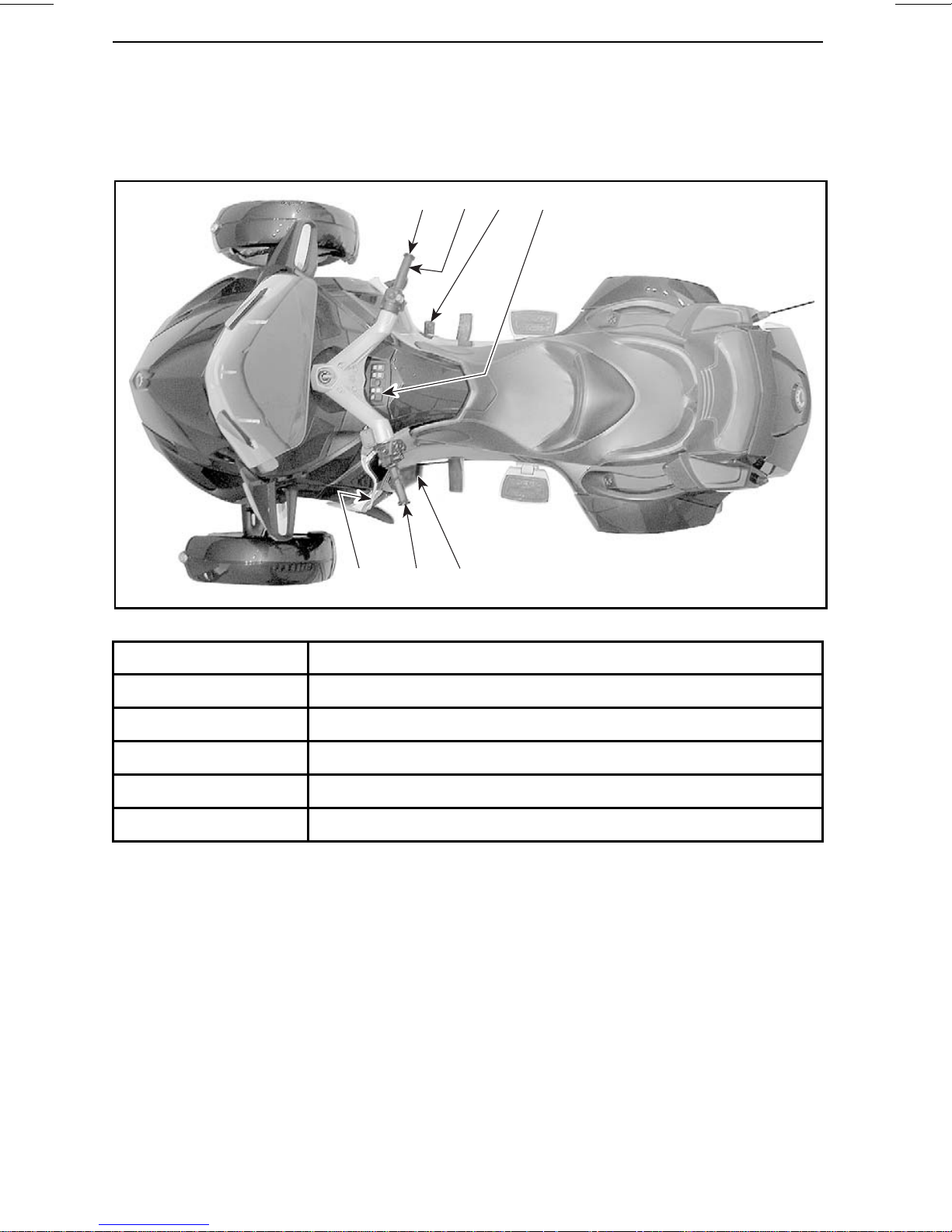
Many controls are similarto the controls of a motorcycle, but some controls are different. It is important to know the location and operation of all controls, and to develop and practice smooth and coordinated use of them.
rmo2010-001-008_b
SM5 MODEL
13 4
2 6
71
1
2Throttle
3
4
6 Brake Pedal
7
Handlebar
Clutch Lever
Gearshift Lever
Parking Brake Switch
10
______________
Page 13
rmo2010-001-030_a
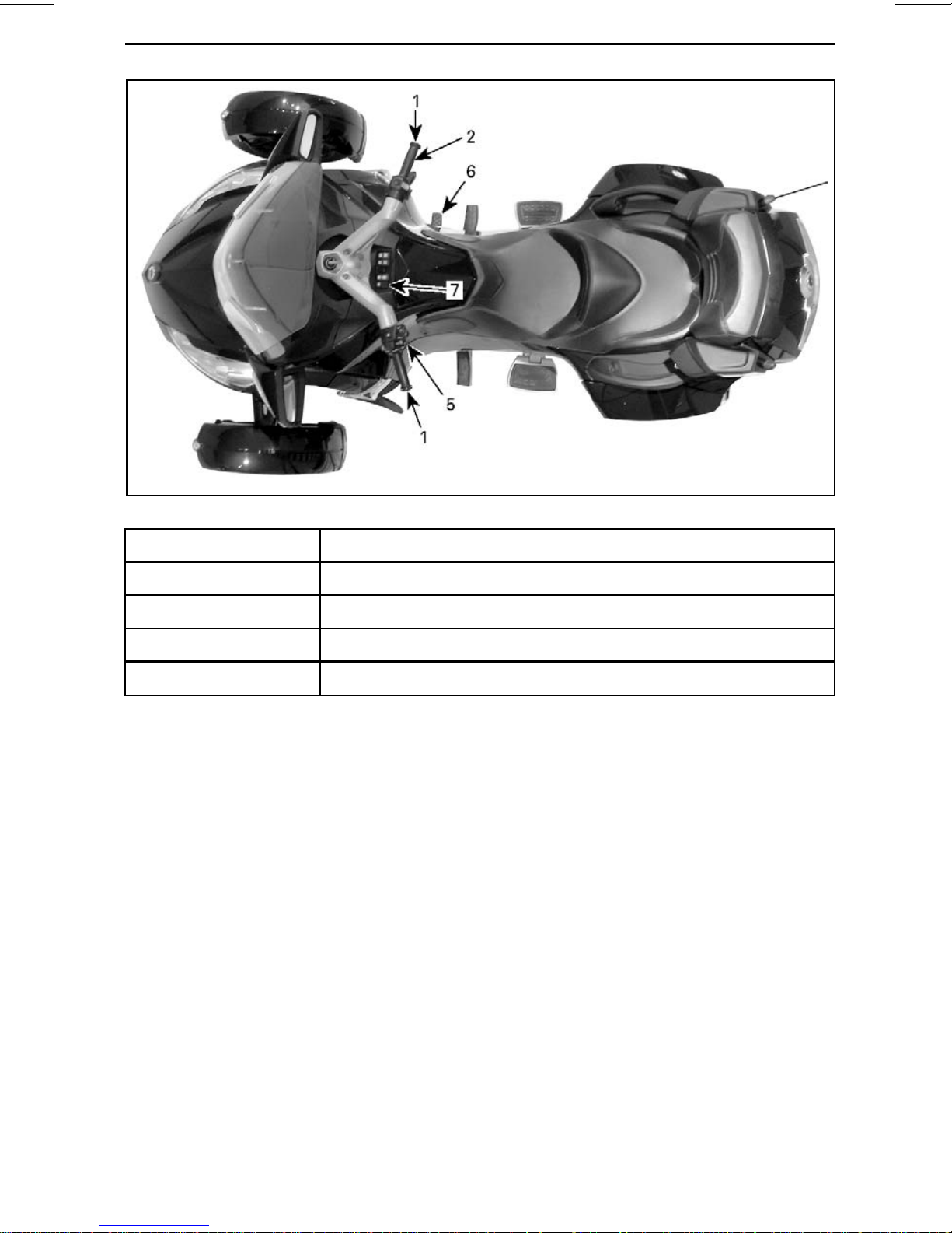
SE5 MODEL - TYPICAL
PRIMARY CONTROLS
1
2Throttle
5
6 Brake Pedal
7
Handlebar
Gearshift Selector
Parking Brake Switch
_______________
11
Page 14
PRIMARY CONTROLS
1) Handlebar
Grip the handlebar with both hands.
Steer the handlebar in the direction
you want to go.
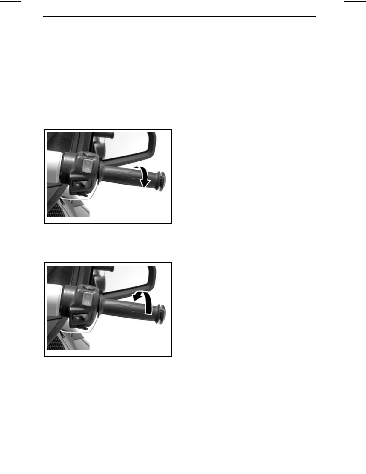
2) Throttle
The throttle is the right handgrip, and it
controls engine speed. To increase engine speed, roll the throttle as shown
(lower your wrist).
rmo2010-001-031_g
TO INCREASE SPEED
NOTE: This vehicle is equipped with
an ETC (Electronic Throttle Control).
The throttle plates in the throttle body
are controlled electronically and can be
opened or closed irrespective of the
throttle twist grip position when necessary. It may happen that when you
accelerate, the VSS (Vehicle Stability
System) prevents engine acceleration
in order to maintain vehicle stability.
Then, when the vehicle is stabilized,
the engine RPM would increase as requested if the throttle was maintained.
This would be felt as a "delayed" acceleration.
3) Clutch Lever
(SM5 Model)
The clutch lever is in front of the left
handgrip. The clutch controls the
transmission of power from the engine to the rear wheel. The lever is
squeezed in to disengage power and
eased out to engage power.
To decrease engine speed, roll the
throttle as shown (raise your wrist).
rmo2010-001-031_j
TO DECREASE SPEED
The throttle is spring loaded and should
return to idle when you release your
grip.
Clutch Lever Position Adjustment
The distance between the clutch lever
and handgrip can be adjusted from position1 (greatest distance) to position 4
(smallest distance).
1.Pushtheclutchleverforwardtorelease the adjuster dial. Hold in position.
2. Turn the adjuster dial to the desired
position aligning the dial number
with the dot on the lever.
3. Release the clutch lever.
12
______________
Page 15
rmo2010-001-033_a
CLUTCH LEVER ADJUSTMENT
1. Clutch lever
2. Adjuster dial
3. Dot
PRIMARY CONTROLS
5) Gearshift Selector
(SE5 Model)
The gearshift selector is below the left
handgrip.
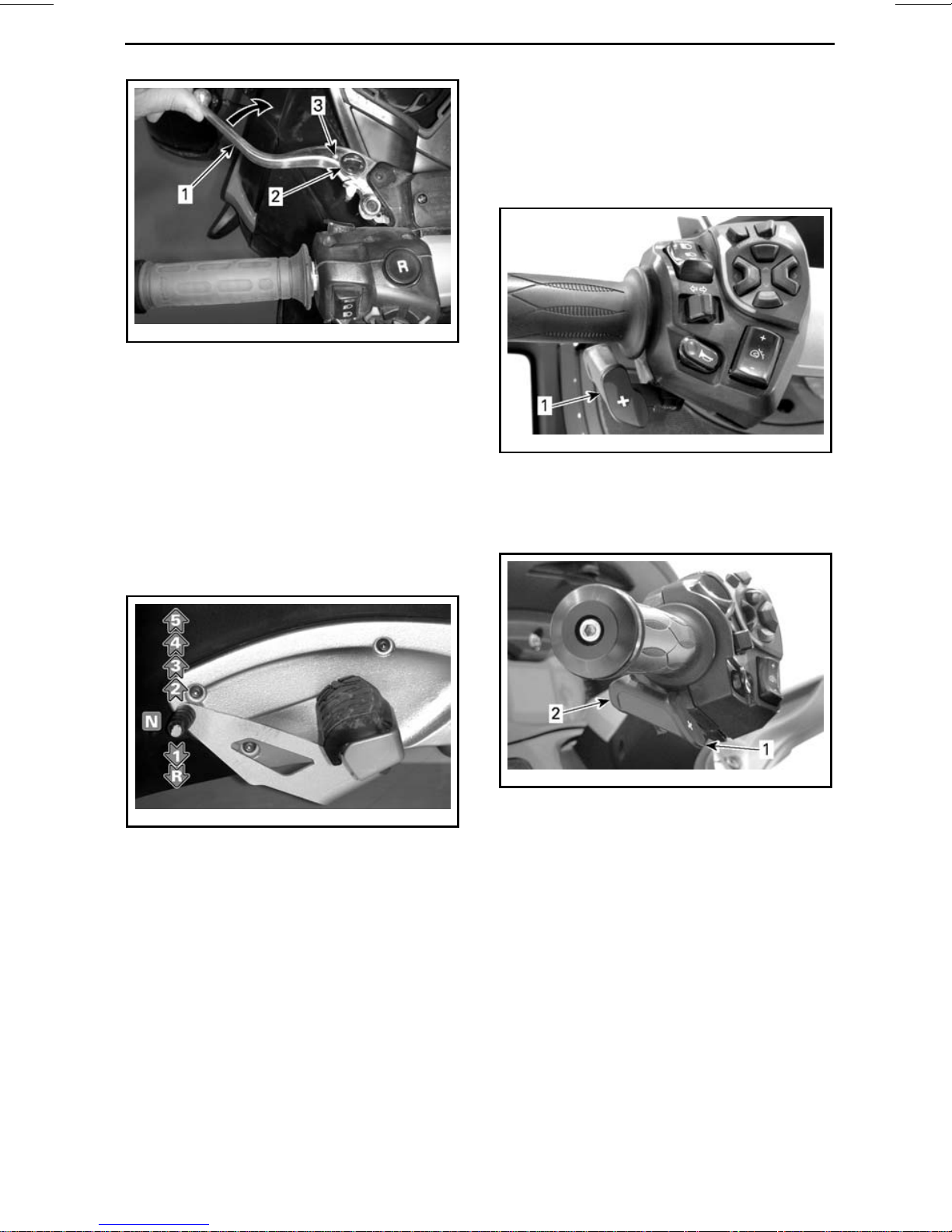
4) Gearshift Lever
(SM5 Model)
The gearshift lever is in front of the left
footrest.
The gear pattern is Reverse-1- Neutral-2-3-4-5.
rmo2010-001-034_a
Lift up or press down fully to move sequentially from one gear to the next.
When the lever is released, it returns
to center where the mechanism resets
forthenextshiftUPorDOWN.Neutral
(N) is selected by either a half lift from
first gear or a half press from seco
gear.
To shift into reverse, refer to
ATING IN REVERSE
DURES
subsection for detailed instruc-
in
the
BASIC PROCE-
tions.
nd
OPER-
rmo2010-001-035_a
1. Gearshift selector
Press selector forward to upshift. Pull
selector toward you to downshift.
rmo2010-001-036_a
1. Upshift
2. Downshift
This shifts sequentially from one gear
to the next. Release the selector after
shifting.
To shift through multiple gears, use the
selector multiple times.
To shift into neutral from first gear or
reverse, briefly press or pull the gear
selector. A longer activation will
shift
over neutral.
When the gearshift selector is r
eleased, the mechanism resets for the
next shift UP or DOWN.
_______________
13
Page 16
PRIMARY CONTROLS
If operator does not downshift when
slowing down and engine RPM drops
below a threshold value, the gearbox
will automatically downshift to the
next available gear.
If the engine is started with gearbox in
gear, it will automatically shift to neutral position.
NOTE: When a trailer is towed, the
trailer mode must be activated to adapt
the gear changes. Refer to
THE TRAILER MODE
NOTICE
If the trailer mode is not
.
SETTING
activated when towing a trailer, engine components might be damaged.
6) Brake Pedal
The brake pedal is in front of the right
footrest. Press it down to operate.
This pedal brakes all three wheels.
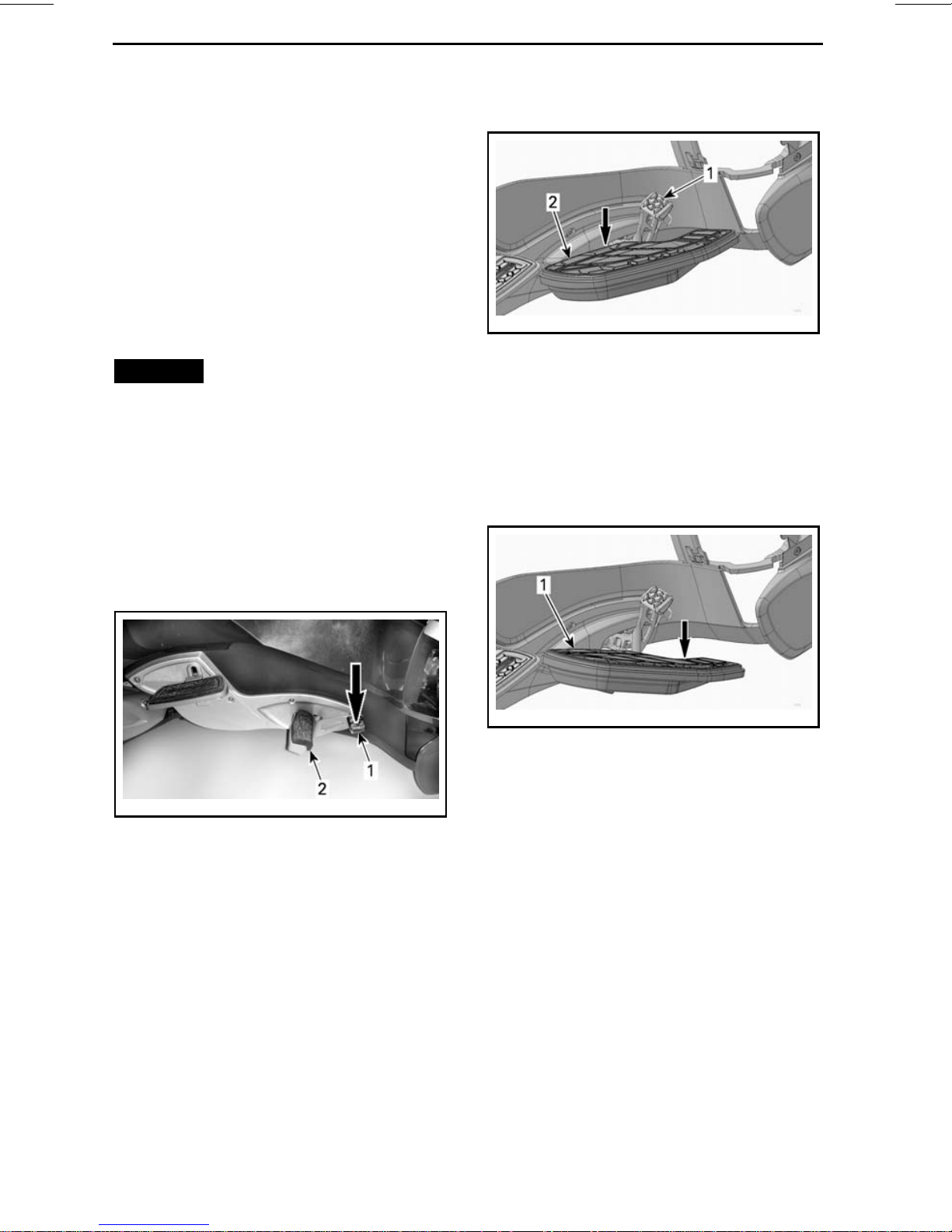
RT-S and RT LTD SE5 Models
rmo2013-005-015_a
NORMAL CONDITION
1. Brake pedal
2. Floorboard
A mechanism allows the floorboard to
lower if the pedal needs to be pressed
more than normal. If that occurs, push
on the rear portion of the floorboard until it clicks and test the braking system.
SM5 Models and SE5 Base Model
rmo2010-001-037_a
1. Brake pedal
2. Footrest
NOTE: When riding, make sure not
to lean your foot on brake pedal. Otherwise, the engine management will
activatethelimphomemodetoprotect the braking system.
rmo2013-005-016_a
LOWERED FLOORBOARD
1. Floorboard
If this condition persists or if you find
any braking system problems, refer to
an authorized Can-Am roadster dealer.
7) Parking Brake Switch
The parking brake switch is located
above the glove box. It allows to engage or release the electric parking
brake.
14
______________
Page 17
PRIMARY CONTROLS
rmo2010-001-038_n
1. Parking brake switch
NOTE: To apply or release the parking
brake, the ignition key must be turned
ON.
NOTE: The battery voltage must be at
10.5 V minimum to activate the parking
brake. If voltage is below 10.5 V, the
parking brake indicator lamp will turn
ON.
Applying Parking Brake
With the vehicle stopped, press switch
to apply the parking brake. The brake
indicator lamp will flash.
rmo2010-001-038_b
1. Press here
rmo2010-001-038_b
1. Press here
NOTE: The parking brake cannot be
activated when the vehicle is above
10 km/h (6 MPH).
Check that the parking brake is fully engaged. Hold the clutch (on SM5 models) and rock the vehicle back and forth.
Releasing Parking Brake
To release parking brake, press and release switch and make sure brake in
cator lamp turns OFF.
di-
_______________
15
Page 18
SECONDARY CONTROLS
rmo2010-001-039_a
1
Ignition switch 8 Horn button
2 Engine start button 9 Windshield adjustment button
3 Enginestopswitch 10
4
Hazard warning switch
5
Cruise control switch
6 Headlight switch 13
7
Turn signal button
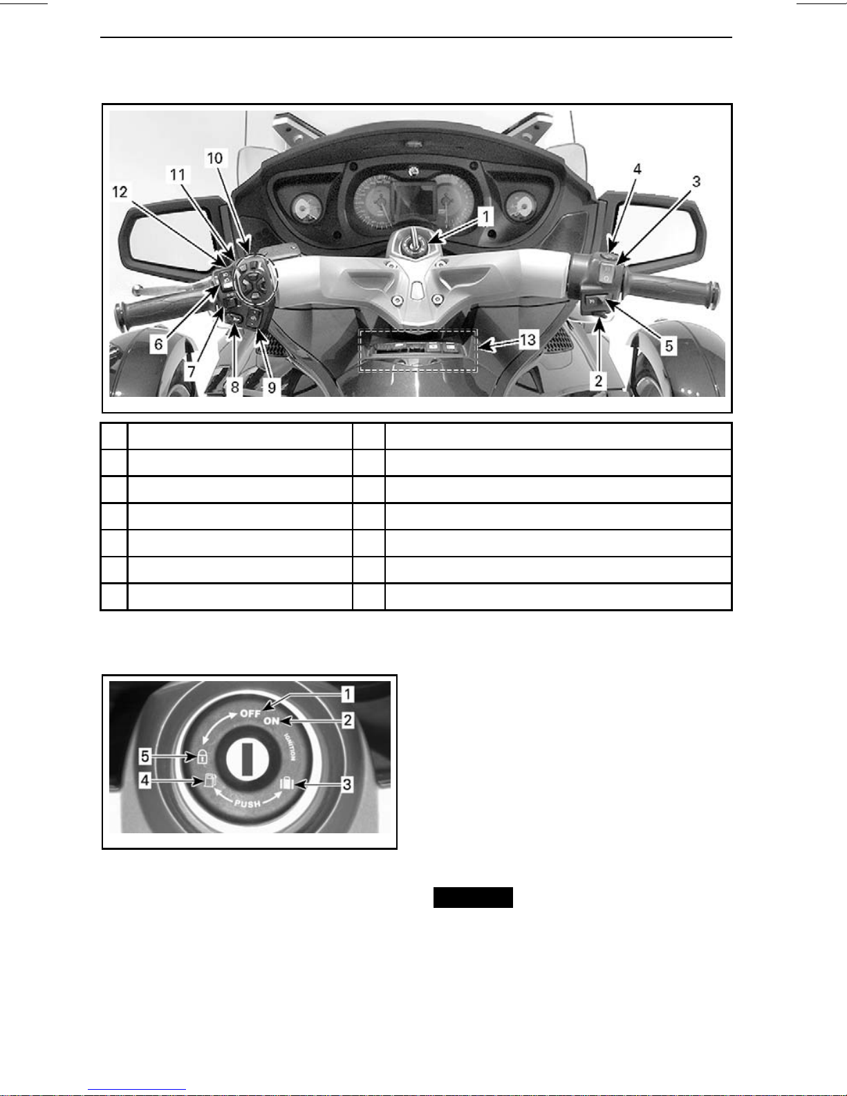
1) Ignition Switch
RECC (Roadster Electronic Command Center)
11
Reverse button
12 PTT (Push To Talk) button
Switch cluster
The ignition switch is located in the
center of the handlebar. It controls:
– Engine ignition
– Seat opening mechanism to access:
• Fuel tank cap
• Brake fluid reservoirs.
– Front storage compartment open-
ing mechanism to access:
• Fuses
rmo2008-001-002_a
IGNITION SWITCH
1. OFF
2. ON
3. Front storage compartment opening
4. Seat opening/fuel tank access
5. Steering/glove box lock position
• Battery terminals.
– Steering/glove box lock mecha-
nism.
NOTICE
If the key does not turn
easily, do not force it. Pull it out and
reinsert.
16
______________
Page 19
WARNING
Ifyouturntheignitionswitchto
OFF, it shuts off the engine and all
the electrical systems including
the VSS and DPS. If you do this
while the vehicle is moving, you
could lose control and crash.
Two keys are provided with your vehicle. Each key contains a transponder
chip specifically pre-programmed to
allow starting the engine. Store the
spare key in a safe place because you
must have your spare key to have
another one made by an authorized
Can-Am roadster dealer.
NOTE: A key barrel is supplied in the
glove box to use with the BRP optional
trailer. This allows to use the vehicle
key for the trailer.
SECONDARY CONTROLS
rmo2010-001-031_a
1. Engine start button
When depressed and held, it starts the
engine.
3) Engine Stop Switch
The engine stop switch is near the right
handgrip.
Ignition Function
OFF
The key can be inserted or removed in
this position only.
In the OFF position, the electrical system of the vehicle is disabled.
The engine is shut down by turning the
ignition switch to the OFF position.
ON
When the key isturned to thisposition,
the electrical system of the vehicle is
activated.
The gauge should wake-up.
The vehicle lights are turned on.
The engine can be started.
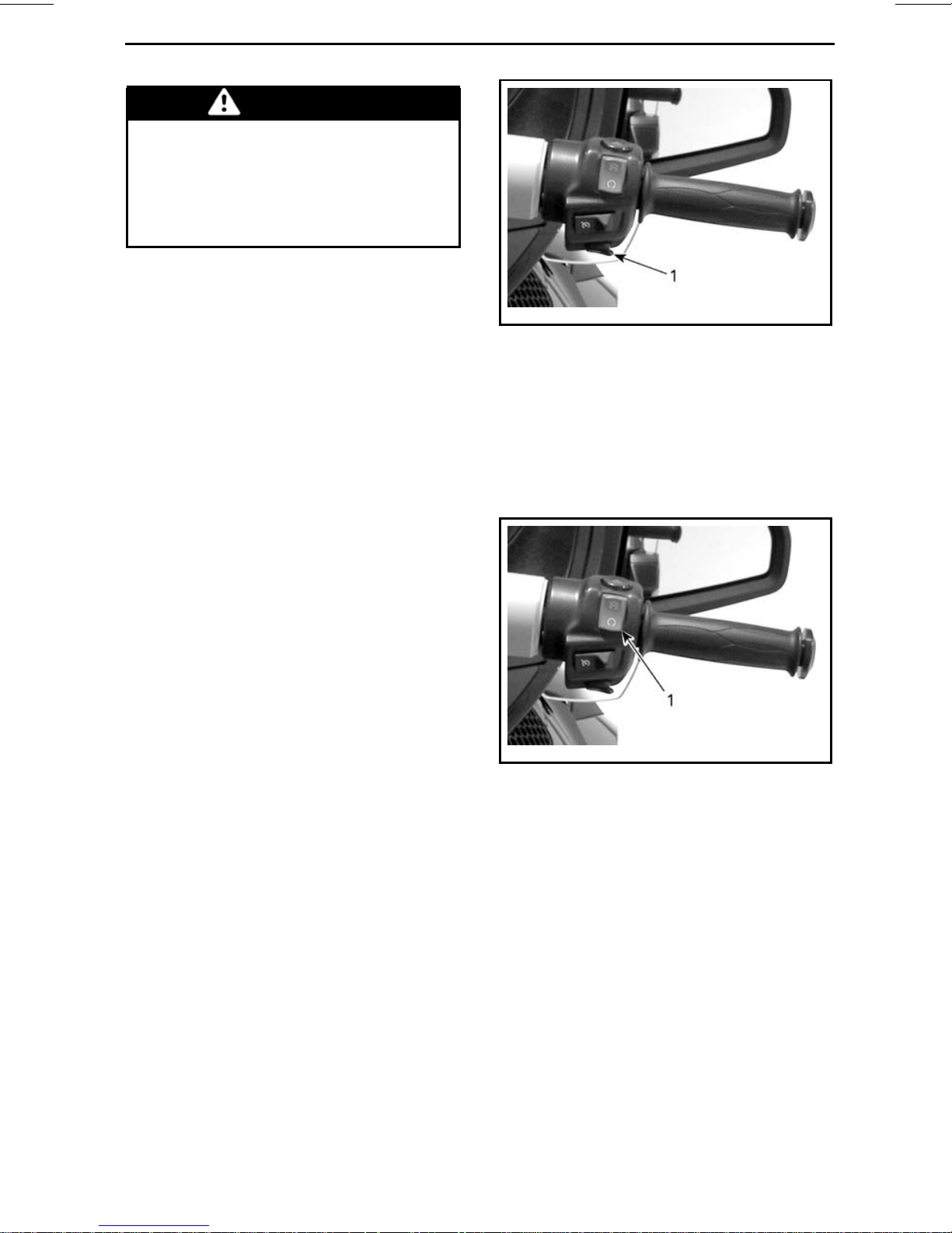
2) Engine Start Button
The engine start button is near the right
handgrip.
rmo2010-001-031_b
1. Engine stop switch
The switch has two positions and must
be set to the run position before you
can start the engine. It allows you to
stop the engine anytime without removing your hand from the handlebar.
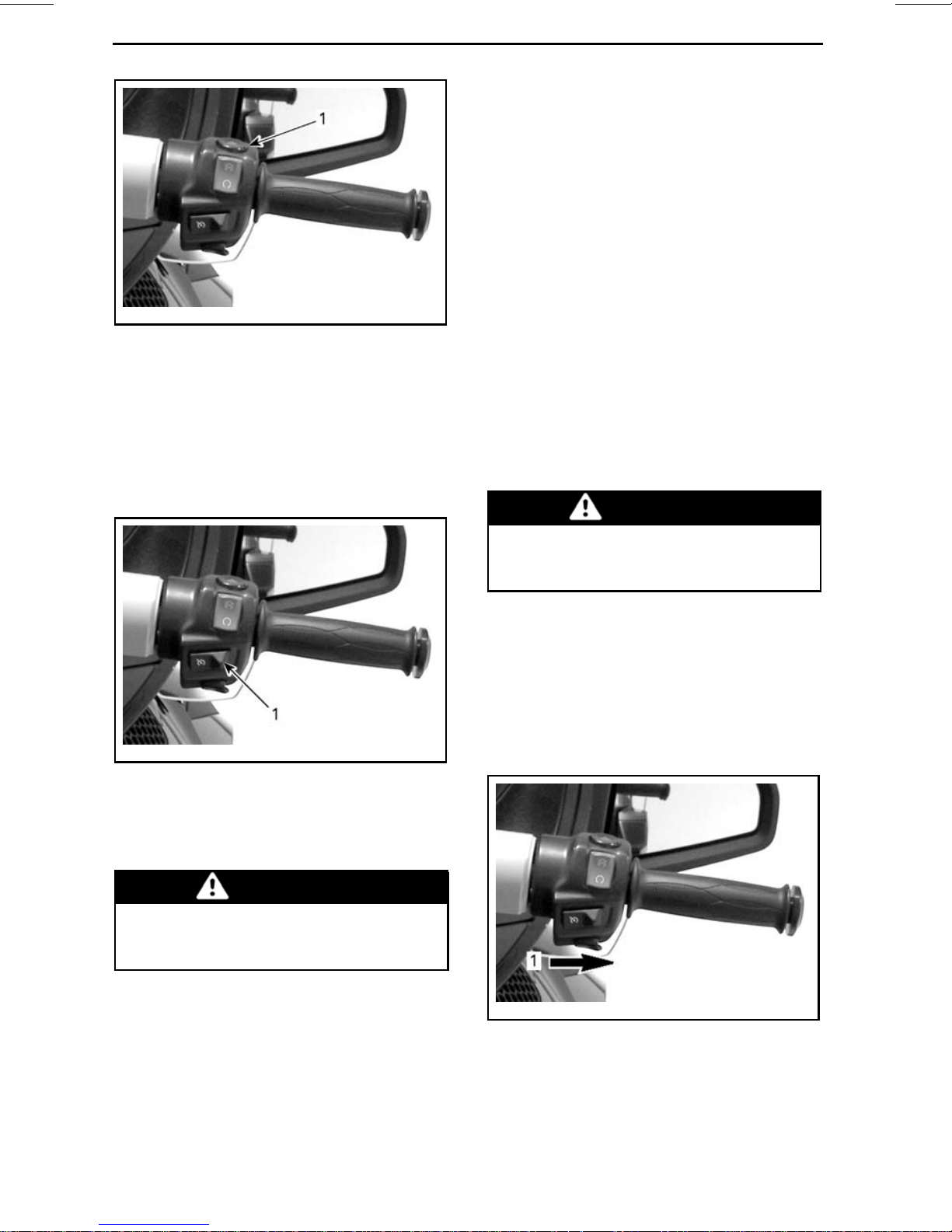
4) Hazard WarningSwitch
The hazard warning switch is near the
right handgrip.
_______________
17
Page 20
SECONDARY CONTROLS
rmo2010-001-031_c
1. Hazard warning switch
Push the button down to turn on the
hazard warning lights.
NOTE: The vehicle torque may vary
slightly depending on the road conditions such as the wind, going downhill
or uphill.
The cruise control is designed to be
used for prolonged drives on low traffic highways. Never ride the vehicle
with the cruise control activated in
city streets, winding roads, in adverse
weather or in any circumstances when
you need the throttle control.
Cruise Control Limitations
The cruise control is not an automatic
pilot, it will not drive the vehicle.
5) Cruise Control Switch
The cruise control switch is near the
right handgrip.
rmo2010-001-031_d
1. Cruise control switch
The switch is a multifunction switch.
It allows to activate, set and stop the
function of the cruise control.
The cruise control is not aware of what
isgoingontheroadanditdoesnot
steer or apply the brakes for you.
WARNING
Improper use of the cruise control
canleadthevehicletoalossof
control.
Setting the Cruise Control
To use the cruise control, the vehicle
speed must be above approximately
40 km (25 mi).
Turn the cruise control to ON by sliding
the cruise control button to the right.
WARNING
It is not recommended to use
the cruise control when towing
atrailer.
When set, the cruise control allows to
maintain a steady speed while riding
the vehicle. It will increase or reduce
engine speed as necessary.
18
______________
rmo2010-001-031_e
1. Slide button to the right
NOTE: The cruise control status will
show CRUISE ON in the digital display.
Page 21
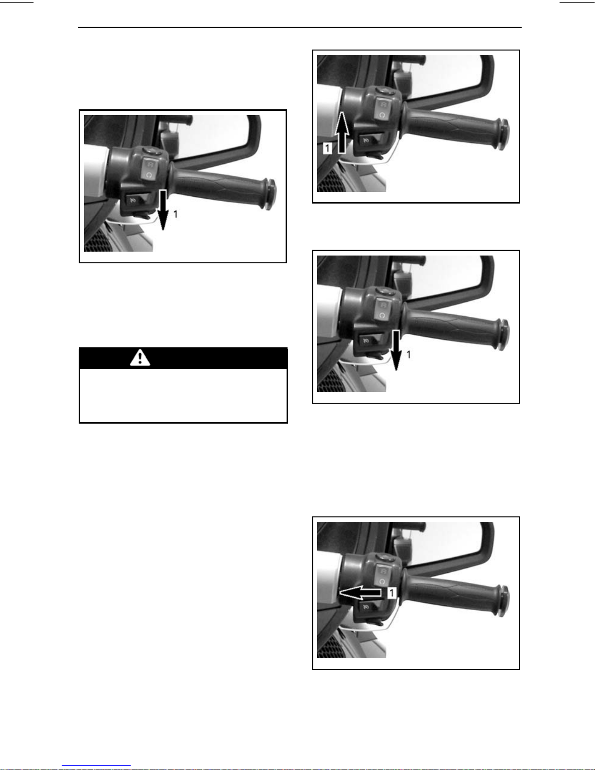
Bring the vehicle at the speed you want
to maintain then press the cruise button downward to SET the speed.
rmo2010-001-031_f
1. Push button downward to SET
NOTE: The cruise control status will
show CRUISE SET in the digital display.
SECONDARY CONTROLS
rmo2010-001-031_i
CRUISE CONTROL PREVIOUSLY SET
1. Push up button to increase the speed
setting
You can now release the throttle.
WARNING
Always keep both hands on the
handlebar while riding. Otherwise, this could cause a vehicle
loss of control.
NOTE: You can increase engine speed
using the throttle grip if you need to go
faster than the set speed. Releasing
the throttle will allow the cruise control
to recover the set speed.
Once the cruise control has been set,
the speed setting may be increased
or reduced by pushing the button UP
or DOWN. Each press of the button
will change the speed setting by increments of 1.6 km/h (1 MPH). Holding
the button will change the speed setting until released or the operating limit
has been reached.
rmo2010-001-031_f
CRUISE CONTROL PREVIOUSLY SET
1. Push down button to reduce the speed
setting
Stopping the Cruise Control
To completely stop the cruise control
operation, slide the cruise control buttontotheleft.
rmo2010-001-031_h
1. Slide button to OFF
_______________
19
Page 22

SECONDARY CONTROLS
NOTE: The cruise control status will
show CRUISE OFF in the digital display.
Cancelling the Cruise Control
Any of the following event will cancel
the cruise control and give you back
the throttle control. It then can be resumed if desired.
– Pressing the brake pedal.
– Squeezing the clutch lever or if
clutch slippage occurs (SE5 mod-
els).
– Gear change (SE5 model).
– Any vehicle stability system inter-
vention.
NOTE: When cancelling the cruise
control, you may activate the throttle lever up to the desired position to
make the transition smoother.
Resuming the Cruise Control
If the cruise control was cancelled and
the cruise control switch is still at the
ON position, the cruise control operation can be resumed by pushing the
cruise control button up. The cruise
control will then recover the previous
set speed.
6) Headlight Switch
Headlights
The switch is near the left handgrip.
rmo2010-001-020_b
1. Headlight switch
The switch is used to select high or low
beam for the headlight. The headlights
automatically turn on when the engine
reaches800RPMandturnoffafterapproximately 20 seconds when engine
has been stopped.
To select high beams, push the switch
to the front position. To select low
beams, push the switch to the back
position.
To flash the high beams, press the
switch to the down position, then release it. The high beams will stay on as
long as you hold down the switch.
rmo2010-001-031_i
CRUISE CONTROL PREVIOUSLY
CANCELLED
1. Push up button to RESUME
NOTE: The cruise control status will
show CRUISE SET in the digital d
play.
20
______________
is-
rmo2010-001-020_f
1. High beams
2. Low beams
3. Flash high beams
Page 23
7) Turn Signal Button
Left side
turn signal
Right side
turn signal
SECONDARY CONTROLS
The turn signal button is located near
the left handgrip.
rmo2010-001-020_g
1. Turn signal button
The turn signal button turns off automatically after a normal turn, but you
may have to turn it off manually after a
shallow turn or lane change.
To turn the signal off, press the button
in.
Turn signals will automatically turn off
after 30 seconds while the vehicle is
moving.
rmo2010-001-020_c
1. Horn button
9) Windshield Adjustment
Button
The windshield adjustment button is
located near the left handgrip.
rmo2010-001-020_h
1. Windshield adjustment button
The button allows to raise or lower the
height of the windshield to your convenience.
8) Horn Button
The horn button is located near the left
handgrip.
CAUTION Ensure there is no
object or anyone hand in the windshield area before adjusting the
windshield height. It could damage
the vehicle or cause injuries.
To raise the windshield, press the button (+ sign). Release the button when
the desired height is reached.
To lower the windshield, press the button (- sign). Release the button
when
the desired height is reached.
_______________
21
Page 24
SECONDARY CONTROLS
rmo2010-001-020_i
1. To raise windshield
2. To lower windshield
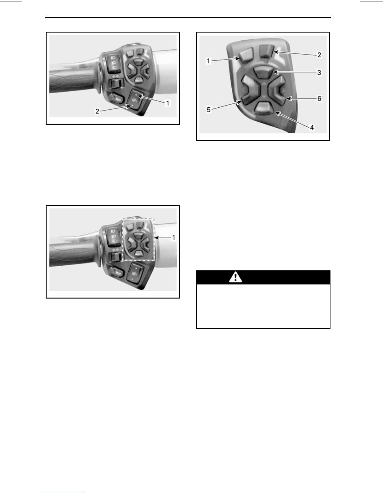
10) RECC
(Roadster Electronic
Command Center)
The RECC is located near the left handgrip.
rmo2010-001-021_a
RECC BUTTONS
1. MODE button: Navigate through the
screens
2. SET button:
Quick press then release: Navigates
through the secondary screens
Holding button more than 1 second: Sets
a value in the current function or navigate
to a setup screen
3. UP button: Increase the volume (audio) or
avalue
4. DOWN button: Decrease the volume
(audio) or a value
5. LEFT button: Move the screen arrows to
the left to select a secondary menu or a
setting
6. RIGHT button: Move the screen arrows
to the right to select a secondary menu or
a setting
rmo2010-001-020_a
1. RECC
The RECC is a multifunction switch.
The RECC allows the control of nu-
merous functions of the multifunction
gauge.
NOTE: Inputs given to the RECC may
be halted for a short delay as the vehicle electronic modules prioritize vehicle main functions. This should not be
considered a malfunction.
WARNING
Using the RECC while driving can
distract the driver from operating
the vehicle. Always use buttons
with caution and always keep your
eyes on the road.
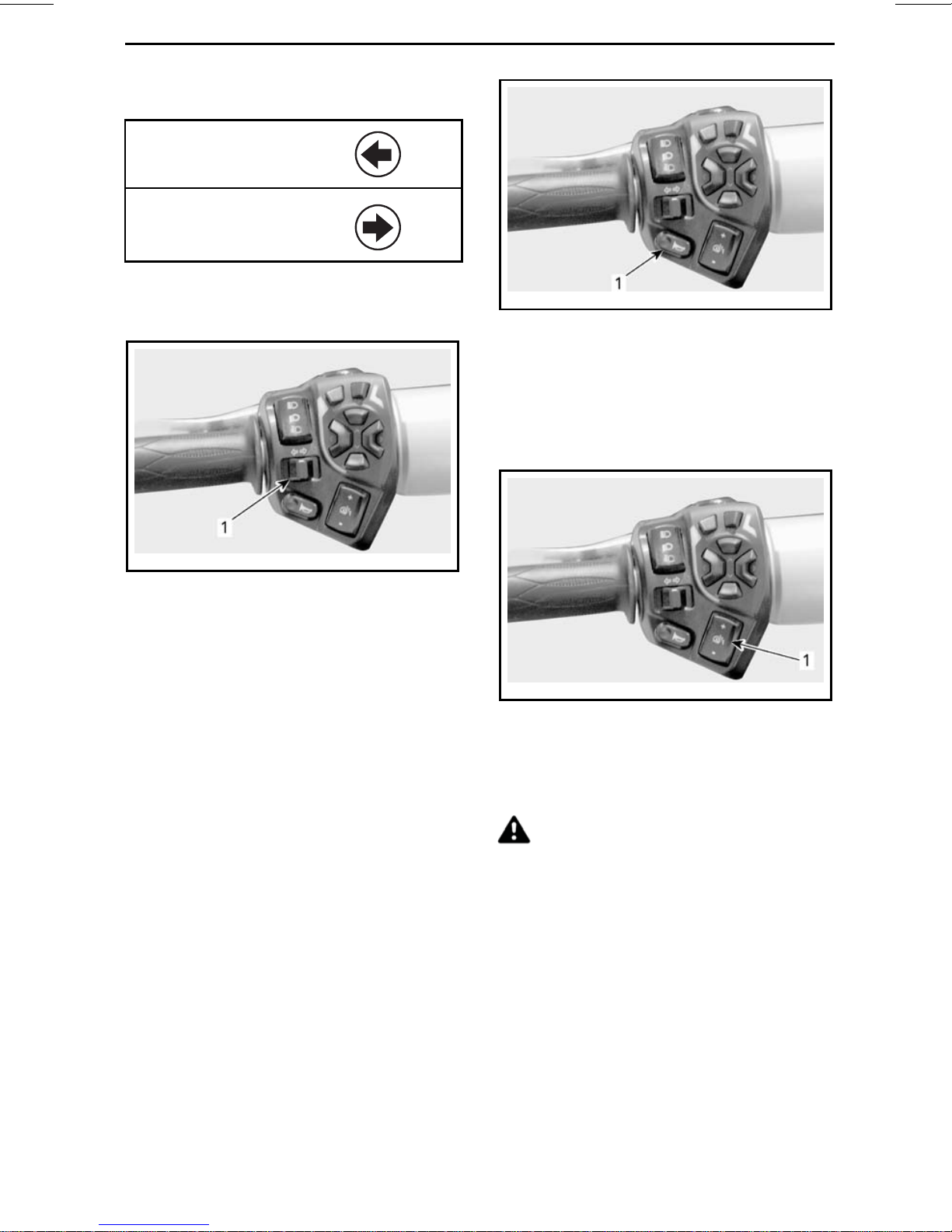
11) Reverse Button
The reverse button is located on top of
the left handlebar housing.
22
______________
Page 25
rmo2010-001-020_e
1. Reverse button
SECONDARY CONTROLS
NOTE: The switch cluster is operational only when the engine is running
and the battery voltage is over 11Vdc.
Push and hold the reverse button to
allow shifting into reverse. Refer to
OPERATING IN REVERSE
PROCEDURES
subsection for detailed
in
BASIC
instructions.
The backup lights turn on when theve-
hicle is in reverse.
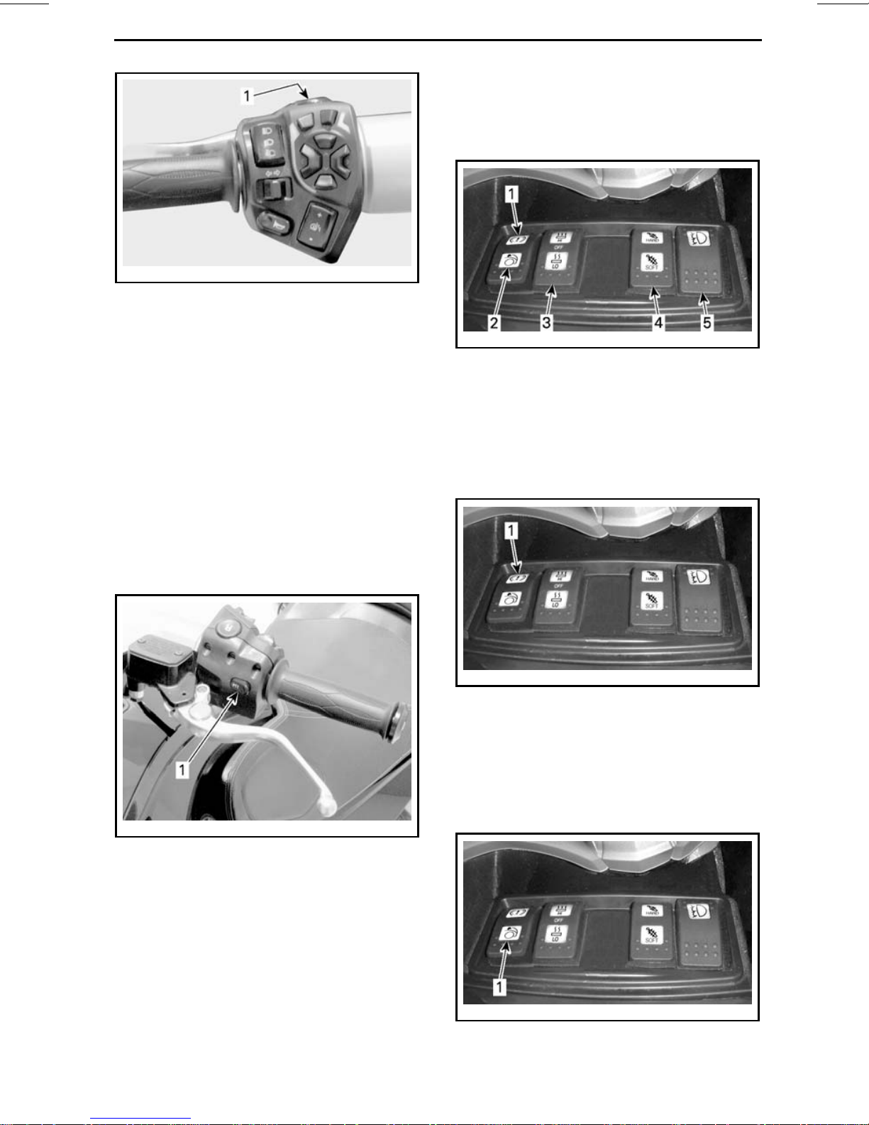
12) PTT (Push To Talk)
Button
The PTT button is located on the left
handlebar housing facing the clutch
lever.
rmo2010-001-038_c
1. Parking brake switch
2. Front storage compartment switch (option
package)
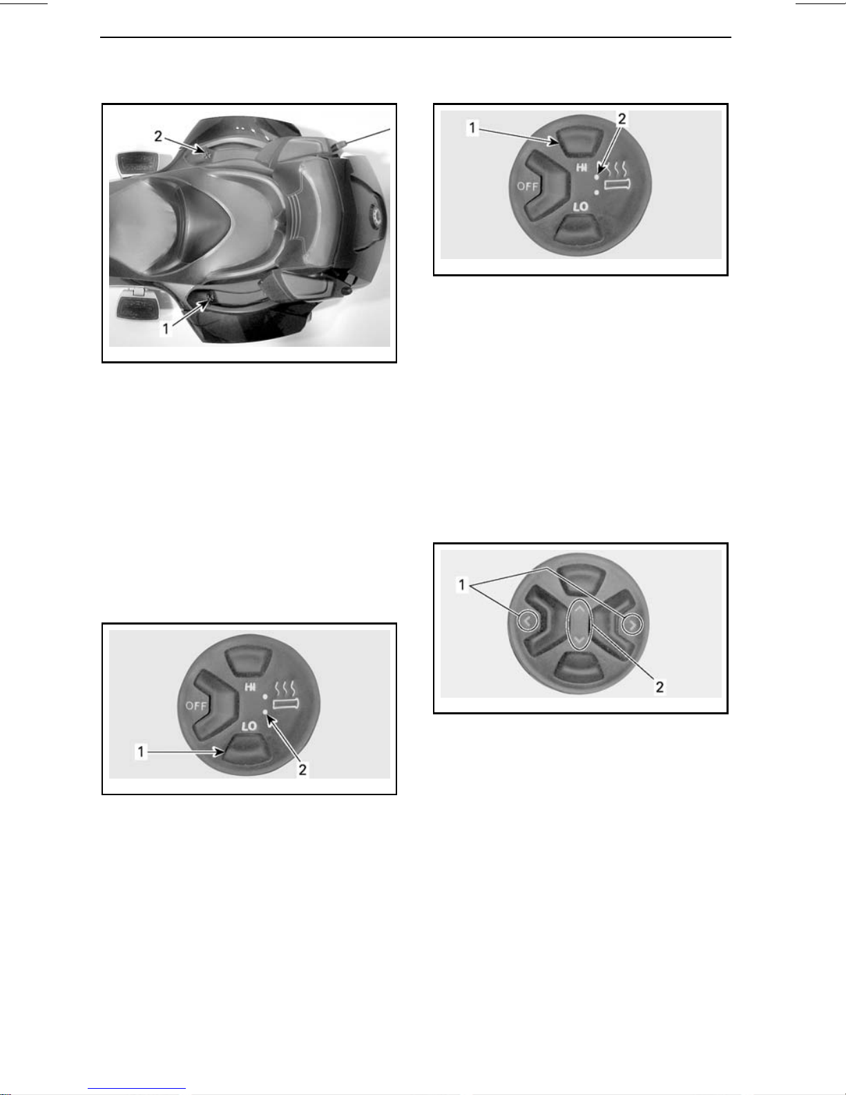
3. Driver's heated grip switch
4. ACS switch (option package)
5. Fog light switch (option package)
Parking Brake Switch
rmo2010-001-038_d
1. Parking brake switch
Refer to the
PRIMARY CONTROLS
subsection for detailed instructions.
rmo2010-001-040_a
1. PTT button
Whenan optionalCB (Citizens'Band)
installed, pressing the button sets the
CB in transmitting mode to talk to other
parties.
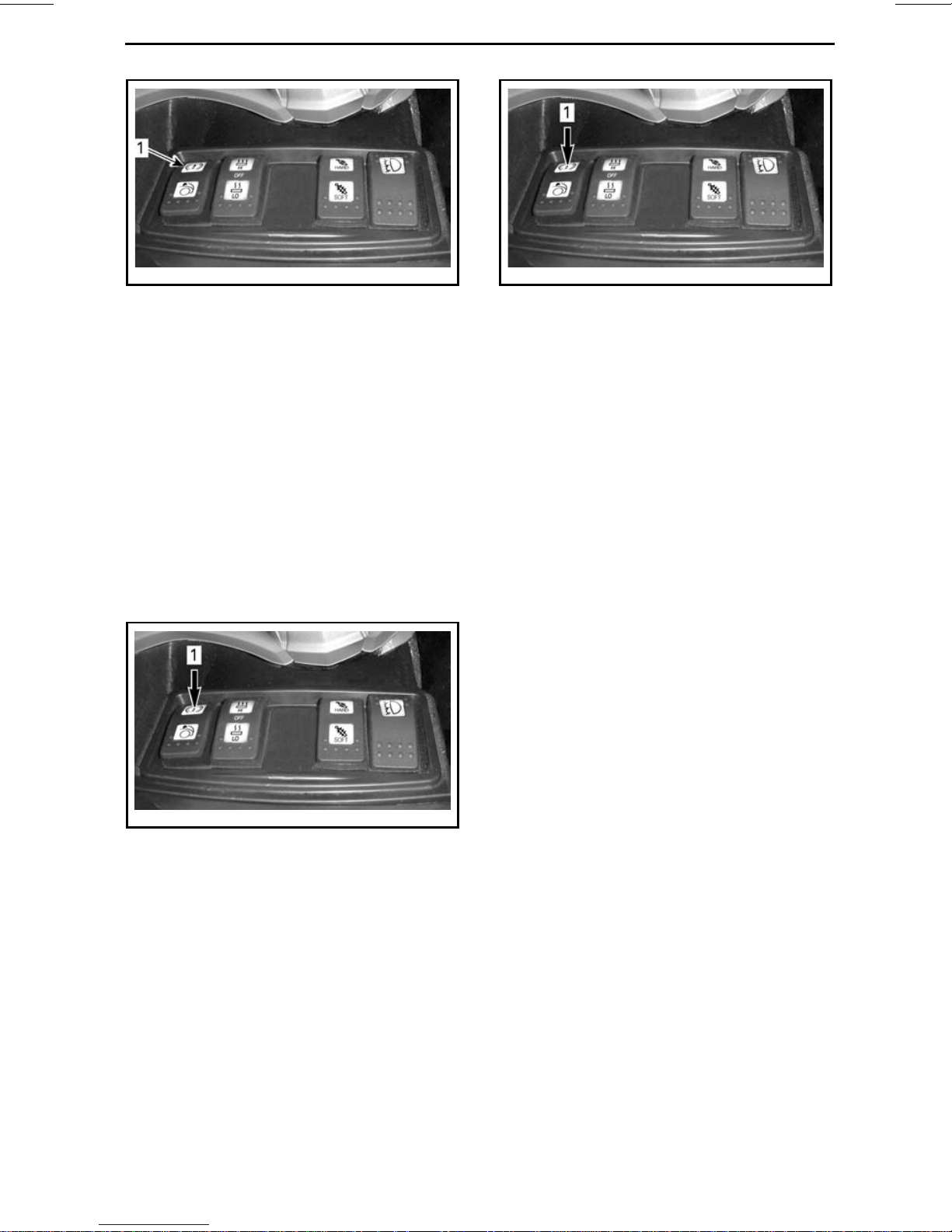
13) Switch Cluster
The switch cluster is locateda
glove box. It gives control of numerous
electrical accessories.
Front Storage Compartment
Switch (Option Package)
is
bove the
rmo2010-001-038_e
1. Front storage compartm
ent switch
_______________
23
Page 26
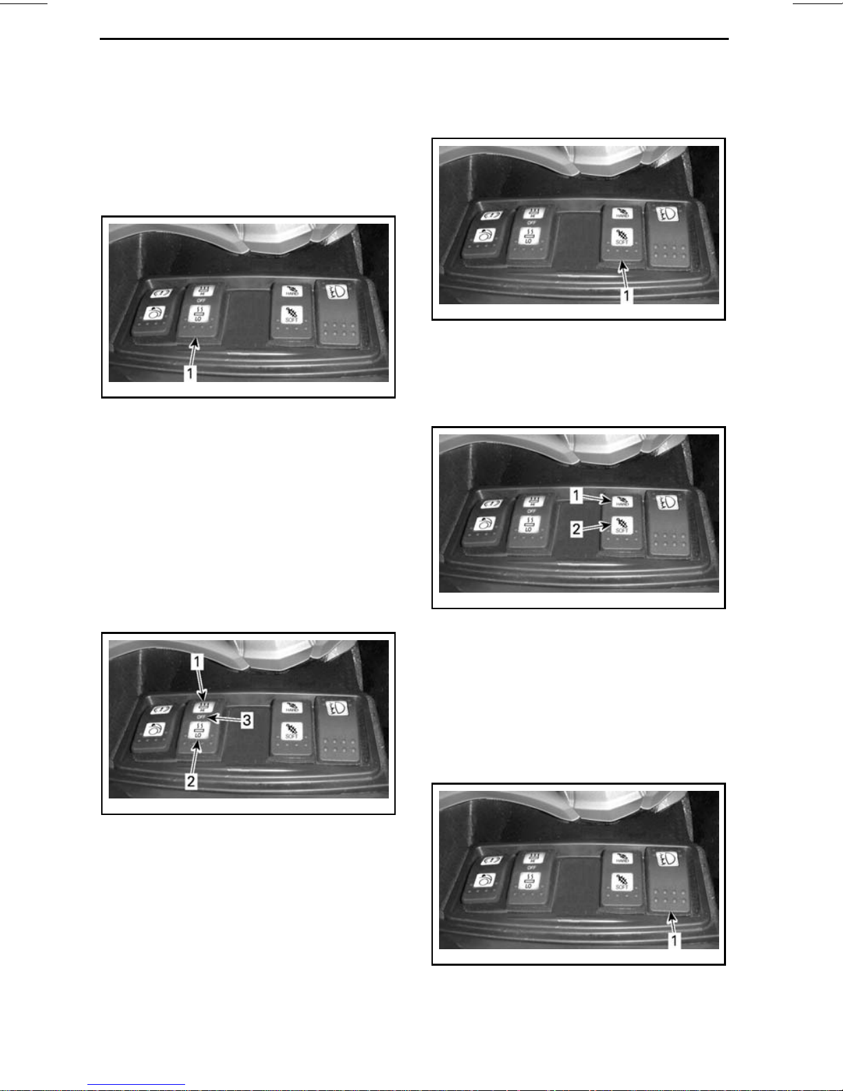
SECONDARY CONTROLS
The switch allows the release of the
front storage compartment latch to
open the cover with the key ON.
Press the switch to unlock.
Driver's Heated Grip Switch
rmo2010-001-038_f
1. Heated grip switch
The heated grip switch allows to turn
onandofftheheatedgripsandtocontrol the heating intensity.
ACS (Rear Suspension) Switch
(Option Package)
rmo2010-001-038_h
1. ACS switch
The ACS switch allows to stiffen or
soften the suspension from factory
settings.
For minimum heat, press the LO intensity side of the switch.
For maximum heat, press the HI intensity side of the switch.
To select the OFF position, set the
switch to the middle position.
rmo2010-001-038_g
1. HI intensity
2. LO intensity
3. OFF (middle position)
NOTE: The heated grips will automatically turn off when ignition key
is turned to OFF.
rmo2010-001-038_i
1. Press here to stiffen
2. Press here to soften
To change the ACS suspension setting,
refer to
ACS REAR SUSPENSION ADJUSTMENT (WITH REMOTE ADJUSTMENT)
Fog Light Switch (Option Package)
.
24
______________
rmo2010-001-038_k
1. Fog light switch
Page 27
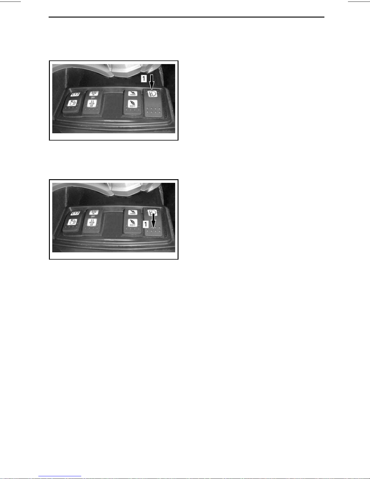
Press on the switch icon to turn on the
fog lights.
rmo2010-001-038_l
1. Press here to turn on
Press the switch to the opposite icon
side to turn off the fog lights.
SECONDARY CONTROLS
rmo2010-001-038_m
1. Press here to turn off
_______________
25
Page 28
PASSENGER CONTROLS
rmo2010-001-029_b
1. Passenger Heated Grip Switch
2. Passenger Audio Control (option)
Passenger Heated Grip
Switch
The heated grip switch is located near
the left passenger grip.
The heated grip switch allows to turn
onandofftheheatedgripsandtocontrol the heating intensity.
rmo2011-001-002_a
1. HI intensity button
2. HI intensity indicator
To select the OFF position, press the
OFF button.
NOTE: The heated grips will shut off
when engine is under 800 RPM and
will not resume automatically.
Passenger Audio Controls
The audio controls are located near the
right passenger grip.
For minimum heat, press the LO intensity button.
rmo2011-001-002_b
1. LO intensity button
2. LO intensity indicator
For maximum heat, press the HI intensity button.
rmo2010-001-089_a
1. LEFT/RIGHT buttons
2. UP/DOWN buttons
The passenger audio controls allow to
remotely increase or reduce the passenger headset volume by using the
UP/DOWN button.
The radio preset station or the song
in an iPod mobile digital device can be
changed using the LEFT/RIGHT buttons.
For additional information on audio
functions, refer to
AUDIO CONTROLS
subsection.
26
______________
Page 29
MULTIFUNCTION GAUGE
WARNING
Watching or using the multifunction gauge or the infotainment center
can distract the driver from the operation of the vehicle. Always keep on
observing the traffic and make sure the surrounding is clear and safe before
doing so.
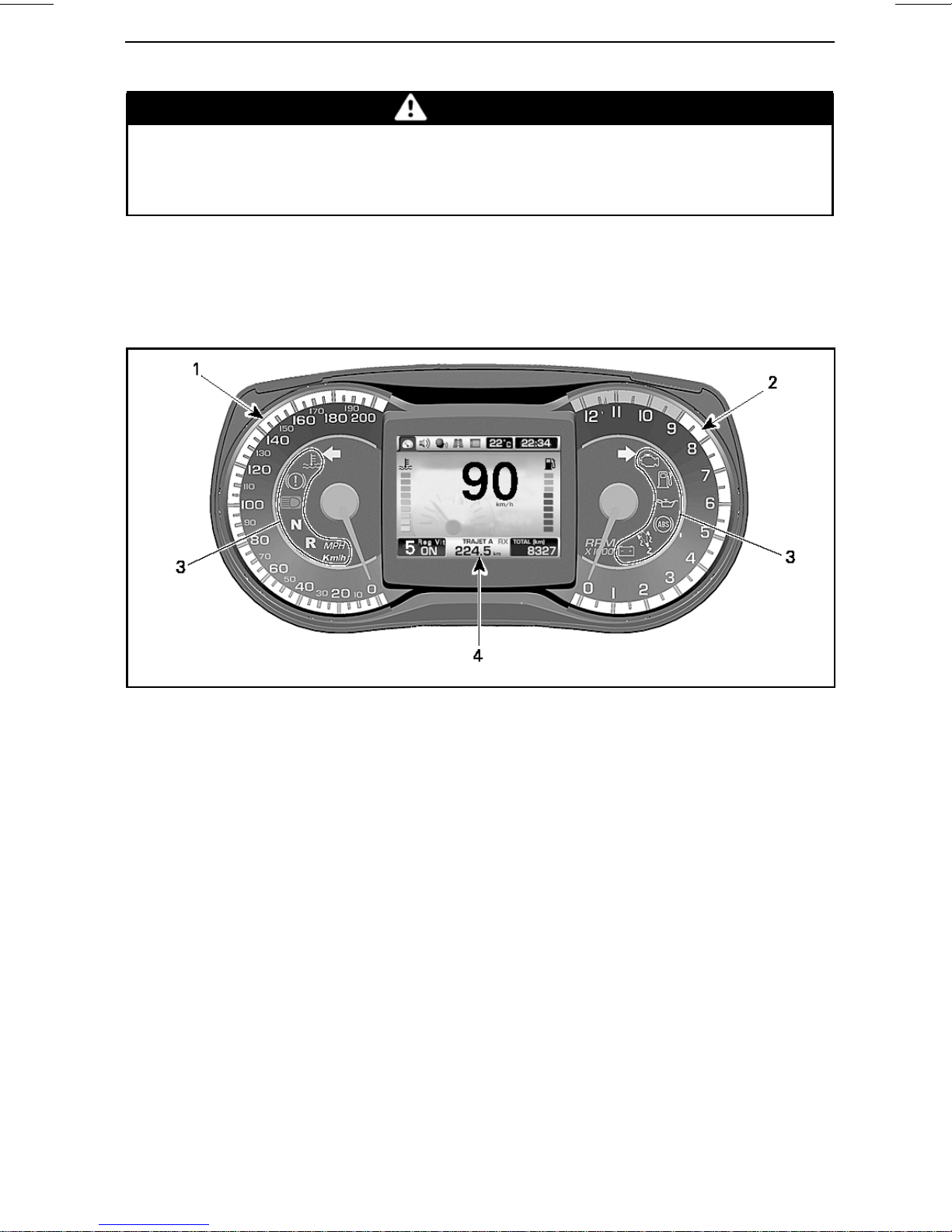
The multifunction gauge includes analog gauges (speedometer and tachometer),
indicator lamps and an infotainment center with a digital screen.
Multifunction Gauge Description
rmo2013-001-016_afr
1) Analog Speedometer
Displays vehicle speed in kilometers
(km/h) or miles per hour (MPH). To
change units, refer to
SCREEN
.
PREFERENCES
2) Analog Tachometer
(RPM)
Displaysengine revolutionsper minute
(RPM). Multiply by 1000 to obtain actual revolutions.
3) Indicator Lamps
Indicator lamps will inform you of various conditions or problems.
_______________
27
Page 30
MULTIFUNCTION GAUGE
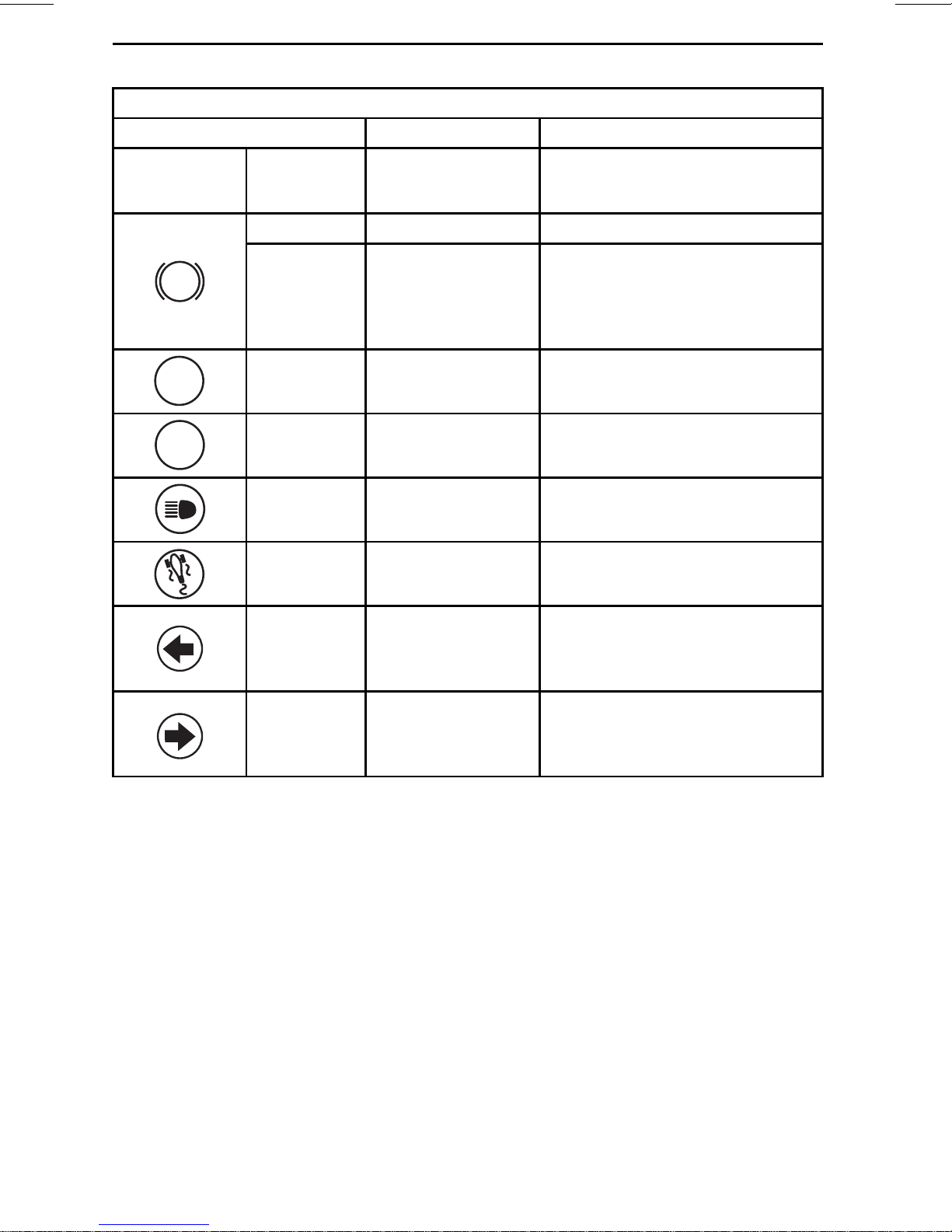
INDICATOR LAMPS (NORMAL OPERATION)
INDICATOR LAMP(S) MAIN SCREEN DESCRIPTION
All indicator
lamps
!
N
R
Temporarily all indicator lamps are
On
Flashing None Parking brake engaged
Flashing +
Beeper
On
Flashing None
On
Flashing None
None
None
None
None
activated when ignition switch is
ON and the engine is not started
SE5 model: The ignition switch
is OFF and the parking brake is
not engaged. Always engage the
parking brake when parking the
vehicle
Gearbox in neutral position
Gearbox in reverse position
Headlights in the HIGH beam
position
VSS intervention occurs
Flashing None
Flashing None
Left side turn signal.
Left and right side indicator
lights flash at the same time:
hazard warning lights
Right side turn signal.
Left and right side indicator
lights flash at the same time:
hazard warning lights
28
______________
Page 31

INDICATOR LAMPS (MALFUNCTIONS)
MULTIFUNCTION GAUGE
INDICATOR
LAMP(S)
E displayed
instead of
selected gear
None
MAIN DIGITAL
DISPLAY
None
N + R flashing
quickly
BAD KEY
REAR STORAGE
COMPARTMENT
OPEN
COMMUNI-
CATION FAULT
CAUSE WHAT TO DO
Gearbox
position sensor
malfunction
Undetermined
gear position
Wrong or
defective key
Top o r s id e
storage
compartment
cover open
CAN (controller
area network)
communication
problem
Have the vehicle repaired by
an authorized Can-Am roadster
dealer.
Stop vehicle and allow to reach
neutral.
Use the right key for the vehicle
or contact an authorized Can-Am
roadster dealer.
Close and latch cover.
Have the vehicle
repaired by an authorized
Can-Am roadster dealer.
*If vehicle is not functional,
have the vehicle transported to
the nearest authorized Can-Am
roadster dealer.
ABS
On
On
On ABS FAULT
HI TEMP
LIMP HOME
LO BATT VOLT
HI BATT VOLT
Engine is
overheating
Low battery
voltage
High battery
voltage
ABS
malfunction.
No ABS
operation
*Have the vehicle transported to
the nearest authorized Can-Am
roadster dealer.
– Recharge battery
(see
MAINTENANCE
PROCEDURES
– Check battery connections.
*Have the vehicle transported
to the nearest authorized
Can-Am roadster dealer.
NOTE: This message will be
displayed if a defective battery
charger is used.
*Have the vehicle transported to
the nearest authorized Can-Am
roadster dealer.
subsection.
_______________
29
Page 32

MULTIFUNCTION GAUGE
INDICATOR LAMPS (MALFUNCTIONS)
INDICATOR
LAMP(S)
On
!
!
On
On
On
MAIN DIGITAL
DISPLAY
VSS FAULT
LIMP HOME
SEAT SWITCH
DEFECTIVE
EBD FAULT
BRAKE FAILURE
PARKING BRAKE
FAILURE
CAUSE WHAT TO DO
VSS
malfunction
Defective
pillion rider seat
switch
VSS
malfunction
Low brake fluid
level or faulty
sensor
*Have the vehicle transported to
the nearest authorized Can-Am
roadster dealer.
Check fuse (see
REPAIRS
*Have the vehicle transported to
the nearest authorized Can-Am
roadster dealer.
– Check for brake fluid leaks.
– Check brake fluid level and
adjust (see
subsection).
PROCEDURES
– Make sure battery tension
is at least at 10,5 V.
– Check fuse no.1 on
Faulty parking
brake or
component
the left fuse box (see
MAINTENANCE
PROCEDURES
ROADSIDE
MAINTENANCE
subsection).
subsection).
On
CHECK ENGINE
CHECK DPS
CHECK TCM
Engine
management
component
malfunction
Dynamic
power steering
component
malfunction
Transmission
Control Module
component
malfunction
Have the vehicle repaired by
an authorized Can-Am roadster
dealer.
Have the vehicle repaired by
an authorized Can-Am roadster
dealer.
Have the vehicle repaired by
an authorized Can-Am roadster
dealer.
– Remove and reinsert key.
– Have the vehicle repaired
by an authorized Can-Am
roadster deale
r.
30
______________
Page 33

INDICATOR LAMPS (MALFUNCTIONS)
MULTIFUNCTION GAUGE
INDICATOR
LAMP(S)
Flashing
On
MAIN DIGITAL
DISPLAY
LIMP HOME
LIMP HOME
None
CAUSE WHAT TO DO
Important
engine
management
component
or VSS
malfunction
Brake applied
while driving
Low oil
pressure
*Have the vehicle transported to
the nearest authorized Can-Am
roadster dealer.
Make sure to release the brake
completely while vehicle is in
movement.
– Check for oil leaks.
– Check oil level and adjust
MAINTENANCE
(see
PROCEDURES
If the problem remains, have
the vehicle transported to the
nearest authorized Can-Am
roadster dealer.
) subsection.
On
On
On CHECKDPS DPSfault
On
On
*
BRP recommends having the vehicle transported when in LIMP HOME. If you operate
the vehicle in LIMP HOME, avoid abrupt maneuvers and immediately go to the nearest
authorized Can-Am roadster dealer to have your vehicle serviced before riding again. In
LIMP HOME, the engine RPM is limited and therefore the vehicle speed.
None Low fuel level
CHECK
TRANSMISSION
MANUAL
KEY ERR Anti theft
TCM fault
ACS fault
Fill fuel tank (see
PROCEDURES
Have the vehicle repaired by
an authorized Can-Am roadster
dealer.
Have the vehicle repaired by
an authorized Can-Am roadster
dealer.
Have the vehicle repaired by
an authorized Can-Am roadster
dealer.
Key not programmed for the
vehicle. See authorized Can-Am
roadster dealer.
BASIC
subsection).
_______________
31
Page 34

MULTIFUNCTION GAUGE
4) Digital Display
Displays useful real-time information
totheriderandisusedasaninterface
for the infotainment center.
The display will use a light color when
the ambient light is bright and will automatically change to a darker color
when the ambient light is dusky.
For a complete description of the digital display, refer to
DESCRIPTION
DIGITAL DISPLAY
.
Multifunction Gauge
Startup Information
A self test is initiated every time the
ignition key is turned ON. The default
riding screen will turn on and indicator
lights will turn on for a moment. This
allows the operator to validate that all
indicators are working properly.
1
9
rmo2010-001-015_cen
1. Category icons
2. Ambient temperature
3. Clock
4. Gearbox position
5. Cruise control status
6. Trip meter
7. CB communication status (optional)
8. Odometer
9. Main screen
2 3
874 65
Any time the ignition switch is turned
ON after having been in the OFF position for 5 minutes or more, the digital
display will show the following message:
– BEFORE OPERATING READ THE
SAFETY CARD ABOVE THEN
PRESS MODE BUTTON.
Press the MODE button to acknowledge this message to allow engine
starting.
Digital Display Description
The display is divided in several areas
as follows.
1) Category Icons
There are 5 selectable category icons.
Each icon is linked to a different
screen. See table below.
CATEGORY
ICON
CATEGORY ICON
SCREEN
Default riding
Audio
CB (optional)
Trip m eter
Preferences (only
available when vehicle
is stopped, except for
the trailer mode)
32
______________
For a complete description, refer to
CATEGORY ICON SCREEN DESCRIPTION
You can navigate through the category
icons to select several functions and
to change certain settings using the
.
Page 35

RECC (Roadster Electronic Command
Center). Refer to
RECC (ROADSTER
ELECTRONIC COMMAND CENTER)
in
SECONDARY CONTROLS
tion.
2) Ambient Temperature
The ambient air temperature is displayed in °C or °F. To change units,
refer to
3) Clock
PREFERENCES SCREEN
subsec-
.
MULTIFUNCTION GAUGE
The current time is displayed in 24h or
am/pm format. To change the format,
refer to
PREFERENCES SCREEN
.
4) Gearbox Positions
Displays the selected gearbox position.
5) Cruise Control Status
Displays ON when the cruise control is
turned on but not set to any speed.
DisplaysSET when the cruisecontrol is
in operation and a speed has been set.
Displays OFF when the cruise control
is not in use.
6) Trip Meter
Distance travelled in kilometers or
miles since the last reset. Two trip
meters are available and they are identified as "A" and "B". To change units,
refer to
PREFERENCES SCREEN
.
rmr2011-079-006_a
1. Icon
7) CB Communication Status
(Optional)
Displays wether the CB (Citizens'
Band) is receiving (RX) or transmitting
(TX).
8) Odometer
Total distance travelled in kilometers or
miles since the delivery from the factory. To change units, refer to
ERENCES SCREEN
.
PREF-
9) Main Screen
The main screen is the area where the
most information is displayed. The
display will change when navigating
through the available gauge functions.
As a second function, the trip meter
may display an icon to inform the driver
of a malfunction. Refer to
IN MULTIFUNCTION GAUGE
ROAD SIDE REPAIRS
section.
MESSAGES
in the
_______________
rmo2010-001-015_en
TYPICAL – DEFAULT RIDING SCREE
SHOWN
N
33
Page 36

MULTIFUNCTION GAUGE
For a complete description of the
screens, refer to
SCREEN DESCRIPTION
CATEGORY ICON
.
Navigating in the Digital
Display
We recommend you practice selecting
some functions on the infotainment
center before getting on the road. You
will get used to them and they will be
easier to use on the road.
Use the RECC (Roadster Electronic
Command Center) to control the display functions. Refer to
STER ELECTRONIC COMMAND CEN-
in
TER)
section.
SECONDARYCONTROLS
RECC (ROAD-
sub-
1
2
rmo2010-001-015_ben
1. Category icons
2. Default riding icon selected
When the selection is on the last icon,
it will then move to the first icon when
the MODE button will be pressed.
In some screens, vertical or horizontal
arrows are visible. This indicates that
you have to use the LEFT/RIGHT button to change the setting enclosed by
the horizontal arrows and to use the
UP/DOWN button to change the setting enclosed by the vertical arrows.
rmo2010-001-020_a
1. RECC
Pressing the MODE button will move
a selection through the category icons,
located at the top left area of the
screen, in this order: Default riding
screen, Audio, CB, Trip meter and Preferences. Each press of the button will
move the selection to the next available icon. When an iconis selected, its
related screen will appear.
NOTE: The CB icon is skipped when
the vehicle is not equipped with thi
feature. The Preferences Screen is
skipped when vehicle is above 5 km/h
(3 MPH), except for the SE5 mod
el for
the towing mode.
When a double arrow is visible, it indicates the following depending on the
displayed screen:
– Holding the DOWN button when
the volume bar is displayed will
mute the audio system. From the
mute condition, pressing the UP
button will reset the audio volume
to its last setting.
– Holdingthe related arrowbutton will
scroll the values to the end or to the
beginning.
– Using the related arrow button will
scroll the list to reveal the re
items.
s
maining
34
______________
Page 37

2
1
rmo2010-001-022_cen
1. Use the UP/DOWN button to select the
vertical arrows
2. Use the LEFT/RIGHT button to select the
horizontal arrows
When an item is selected, this sets the
item to the current value.
After acknowledging the initial safety
message at gauge startup, or after
a few seconds elapsed in any other
screen without pressing any RECC
button, the display will automatically
return to the default riding screen.
Category Icon Screen
Description
Default Riding Screen
MULTIFUNCTION GAUGE
1) Engine Coolant Temperature
(except Models with Separate
Analog Gauges)
Bar gauge that continuously indicates
the engine coolant temperature.
NOTE: On models with a separate
analog engine coolant temperature
gauge, the bar gauge is not displayed
in the digital display.
2) Fuel Level (except Models with
Separate Analog Gauges)
Bar gauge that continuously indicates
the amount of fuelleft in the fuel tank.
NOTE: On models with a separate
analog fuel level gauge, the bar gauge
is not displayed in the digital display.
3) Digital Speedometer
Displays vehicle speed in kilometers
(km/h) or miles per hour (MPH). To
change units, refer to
SCREEN
.
PREFERENCES
4) Engine Speed
Displays engine speed in revolutions
per minute (RPM).
3
1
4
rmo2010-001-401_aen
DEFAULT RIDING SCREEN
1. Engine coolant temperature (option
package)
2. Fuel level (option package)
3. Digital speedometer
4. Engine speed (not factory s
5. Radio preset or radio frequency (not factory
set)
5
et)
2
NOTE: This is not a default setting. To
activate this function, refer to
ENCES SCREEN
.
PREFER-
5) Radio Preset or Radio Frequency
Displays the selected radio preset or
radio frequency.
NOTE: This is not a default function.
To activate thisfunction, refer to
ERENCES SCREEN
.
PREF-
Audio Screen
The audio screen will appear with its
last configuration.
_______________
35
Page 38

MULTIFUNCTION GAUGE
1
rmo2010-001-022_ben
1. Current selected audio device
For additional information on audio
functions, refer to
AUDIO CONTROLS
CB Screen (Optional)
This screen is only available when a CB
is installed.
NOTE: The CB screen will appear
whenever the PTT (Push To Talk) button is pressed whatever the screen
that was displayed.
Trip Meter Screen
1 2 3
.
rmo2010-001-024_aen
TYPICAL
1. Display selection: Trip A or Trip B
2. Pause or resume the selected trip meter
3. Reset the selected trip meter
Press the LEFT/RIGHT button to select
the desired trip meter.
Press the UP button to pause or resumetheselectedtripmeter.
1 2 3 654
rmo2010-001-023_aen
1. Current channel
2. CB communication status:RX (receiving), TX
(transmitting) and OFF
3. Squelch adjustment
4. Volume adjustment
5. Intercom volume adjustment (i-com)
6. Voice activation sensitivity a
For additional information o
functions, refer to
AUDIO CONTROLS
djustment (vox)
n audio
Press the DOWN button to reset the
selected trip meter.
Preferences Screen
rmr2010-030-058_aen
1. 1stcolumn: Main category
nd
2. 2
3. 3
column: Secondary categor
rd
column: Unit or setting
.
This screen is only available when vehicle is stopped.
yoritem
36
______________
Page 39

NOTE: On SE5 model, the Trailer
Mode in the Preferences Screen is
available while riding.
Use the LEFT/RIGHT button to select
the desired column.
Within a column, use the UP/DOWN
button to select the desired item. If
more items are available to the next
right column, use the RIGHT button
toselectthecolumnthenuseagain
the UP/DOWN button to select the desired item. Continue using this pattern
to reach the desired item.
When an item is selected, this sets
the item to the current value. You may
then go to anyscreen, the value will be
kept.
MULTIFUNCTION GAUGE
rmo2011-001-202_a
Select HOURS in secondary category.
Adjust the unit value using the UP and
DOWN arrow.
To set the minutes:
Select CLOCK in main category of Pref-
erences Screen.
rmr2010-030-057_aen
1. The selected value will be set
NOTE: When in the 2ndor 3rdcolumn,
you can go back to the column at the
left using the LEFT button.
NOTE: When the units are changed
they will be changed on both the analog and the digital displays. The units
will be used for the odometer and both
trip meters.
Setting the Time
To set the hours:
Select CLOCK in main category of Pref-
erences Screen.
rmo2011-001-201_a
Select MINUTES in secondary category.
Adjust the unit value using the UP and
DOWN arrow.
Selecting the Hour Mode
To select the 12/24 hour mode:
Select CLOCK in main category of Pref-
erences Screen.
rmo2011-001-203_a
Select 12/24 HOUR in secondary category.
_______________
37
Page 40

MULTIFUNCTION GAUGE
Select the appropriate value in main
unit or setting.
Selectingthe Region Setting (Audio)
To select the region setting:
Select AUDIO in main category of Pref-
erences Screen.
rmo2011-001-200_a
Select REGION SETTING in secondary
category.
Select the appropriate region according to the table below in main unit or
setting.
REGION COUNTRIES
E
F-Taiwan
G
- Australia
- China
- Argentina
-Brazil
-Cayman
- Chile
- Columbia
-CostaRica
- Malaysia
- New Zealand
- Curacao
- DominicanRep.
- Guadeloupe
-Mexico
-PuertoRico
- Venezuela
Restartthe vehiclein order for changes
to take effect.
REGION COUNTRIES
-USA
A
B
C
D - Japan
- Canada
- South Africa
-Austria
- Bulgaria
-Denmark
-France
-Iceland
-Israel
-Kuwait
-Norway
-Romania
- Benelux
- Germany
-Greece
-Italy
- Slovakia
-Slovenia
-Spain
- Switzerland
-Turkey
-UAE
- UK/Ireland
- Ukraine
- Poland
- Portugal
-Russia
38
______________
Page 41

ANALOG GAUGES (OPTION PACKAGE)
rmo2010-001-107_a
1. Fuel level gauge
2. Engine coolant temperature gauge
Fuel Level Gauge
The needle in gauge continuously indicates the amount of fuel left in the fuel
tank.
rmo2013-005-007_a
FUEL LEVEL
1. Full
2. Empty
Engine Coolant
Temperature Gauge
The needle in gauge continuously indicates the engine coolant temperature.
Under all riding conditions, the needle
should stay within this range.
rmo2013-005-006_a
COOLANT TEMPERATURE
1. Normal operating range
2. Overheat
_______________
39
Page 42

AUDIO CONTROLS
Audio System Power
Follow one of the following steps below to turn the audio system ON:
– Turn ignition switch to ON
– Press MODE button for 3 seconds
immediately after ignition switch is
turned OFF.
Follow one of the following steps belowtoturntheaudiosystemOFF:
– Turn ignition switch to OFF
– If the audio was ON withthe ignition
switch to OFF, press MODE button
for 10 seconds.
Audio Volume Control
When in the default riding screen,
pressing the UP or DOWN button will
increase or decrease the audio volume.
NOTE: On models without a separate
analog fuel level gauge, the fuel level
bars will be replaced by the volume
bars for a few seconds, then the fuel
level bars will come back.
Self-Adjusting Audio
Volume
The audio volume level can be automatically adjusted based on the vehicle speed. This is controlled by the
automatic volume control setting in
the Preferences Screen.
Audio Mute
Press the DOWN button and hold it
more than one second. The audio volume will mute.
From the mute setting, pressing the
UP button will reset the audio volume
to its last setting.
Radio Band
When in the audio screen, repeatedly
pressing the SET button will display
the available audio devices in this order:
–FM
–AM
– WX (NOAA weather radio)
– AUX (iPod device or MP3 player)
–XM.
NOTE: XM is displayed only if so
equipped.
1 3
2
rmo2010-001-022_aen
FM RADIO SHOWN
1. Current selected band
2. Station number preset
3. Current station
4. Volume level
While riding, the available radio functions are:
– Audio volume
– Mute, seek and slew (XM radio)
functions
– Radio preset functions (selection
and storing).
NOTE: The radio is always ON. Use
the MUTE function to cancel the volume.
To listen to the radio while ignition
switch is set to OFF, hold the MODE
button for 3 seconds immediately after
theswitchissettoOFFtopowerup
the digital display.
NOTE: To preserve battery charge, radio may shut off automatically after a
certain period.
Selecting a Radio Preset Station
Press the LEFT/RIGHT button to decrease or increase the preset number.
4
40
______________
Page 43

Press and hold the LEFT/RIGHT button
for more than one second to SEEK the
next available radio station. The radio
will remain tuned to that station.
Press the SET button and hold for more
than one second to enter the setup
screen.
In the setup screen, press the
LEFT/RIGHT button to tune the radio
frequency.
AUDIO CONTROLS
Recording a Radio Preset Station
To record up to 15 preset stations:
Press the DOWN button to record the
actual frequency to the preset number
displayed.
NOTE: While riding, the radio station
will be automatically recorded to the
next available preset number. If all
preset numbers are used, the preset
number 15 will be overwritten.
1
2
3
rmo2010-001-090_b
1. Audioinjack
An audio device can be connected in
this jack to be played through the audio
system.
NOTE: An adapter (optional on some
models) is required to connect the audio device to the vehicle audio jack.
MP3 Player
When an MP3 player is connected to
the vehicle audio connector, it will play
as set at the time of the connection.
Only the volume control will be available.
iPod Device
When an iPod device is connected,
"iPod" is displayed instead of AUX.
rmo2010-001-027_aen
1. LEFT/RIGHT button to select the frequency
2. UP button to select the preset number
3. DOWN button to record the radio station
AUX (Auxiliary)
An audio input jack is provided in the
top storage compartment.
rmr2011-079-011_en
TYPICAL - iPod DEVICE SCREEN
Press the LEFT/RIGHT button to
change the song in the current folder.
_______________
41
Page 44

AUDIO CONTROLS
Press and hold the LEFT/RIGHT button
for more than one second to change
the playlist if the playlist item is selected, to change the artist if the artist
item is selected and to change the album if the album item is selected.
While riding, the available functions
are:
– Audio volume and mute
– Previous or next song selection
– Artist, album or playlist selection.
Compatible iPod Device
Made for:
–iPodtouch(2
nd,3rd
and 4thgenera-
tion)
– iPodnano(5
th
and 6thgeneration)
–iPad
–iPad2
– iPhone 4
– iPhone 3GS
– iPhone 3G.
CB Screen (Optional)
This screen is only available when a CB
is installed.
NOTE: The CB screen will appear
whenever the PTT (push to talk) button is pressed whatever the screen
that was displayed.
1 2 3 654
rmo2010-001-023_aen
1. Current channel
2. CB communication status:RX (receiving), TX
(transmitting) and OFF
3. Squelch adjustment
4. CB volume adjustment
5. Intercom volume adjustment (i-com)
6. Voice activation sensitivity adjustment (vox)
Use the LEFT/RIGHT buttons to select
the item to change (channel, squelch,
CB volume, intercom volume and vox
detection).
Use the UP/DOWN buttons to set a
value.
Press and hold the DOWN button for
more than one second to set the item
to its lowest value.
42
______________
Page 45

GPS (OPTION PACKAGE)
For GPS operation, refer to GPS manual.
WARNING
Reading the GPS receiver can distract from the operation of the vehicle, particularly from constantly
scanning the environment. Before
reading the GPS receiver, ensure
your environment is clear and free
from obstacle, and bring the vehicle to a low speed. Additionally,
make sure to often double-check
for obstacles.
WARNING
Remember, the data provided by
the GPS receiver is for reference
only. NEVER rely solely on this information for your safety.
GPS Receiver Installation
To attach the GPS receiver to its base;
insert the lower part of the GPS receiver first, then tilt the GPS receiver
towards the top of the base.
Install the rubber boot over the GPS
cover plate by starting from the top
and then bottom.
CAUTION The rubber boot
must be installed at all times except
when the GPS is installed onto the
vehicle.
rsi2010-021-019_a
1. GPS base with cover plate installed
2. Cover boot
Push into place until it locks in.
rsi2010-021-017_a
1. GPS receiver
2. GPS base
GPS Receiver Removal
Removal of the GPS receiver is the reverse of installation.
_______________
43
Page 46

EQUIPMENT
Mirrors
Adjusting Mirrors
Press the mirror at the points shown
below to adjust its position in the four
directions.
rmo2010-001-043_a
MIRROR ADJUSTMENT POINTS
Glove Box
Locking the Handlebar/Glove Box
Opening the Glove Box
First ensure steering is not locked to allow glove box opening.
Push on the lower end of glove box to
release it.
rmo2010-001-045_a
1. Push here to release
Open cover.
When done, close cover then push on
the lower end of glove box to latch it.
To lock the steering mechanism and
the glove box:
1. Insert key in ignition switch.
2. Rotate the handlebar all the way to
the right or to the left.
3. Turn the key 1/4 turn counterclockwise to the steering lock position
then remove key.
rmo2010-001-045_a
1. Push here to latch
Always latch the glove box after usage.
NOTE: The glove boxwill be automati-
cally locked when locking the steering.
rmo2008-001-074_a
KEY POSITION TO LOCK HANDLEBAR
1. Turn key 1/4 turn
44
______________
Page 47

EQUIPMENT
Front Storage
Compartment
Opening the Front Storage
Compartment
Using the Ignition Switch
1. Insert key in ignition switch.
2. Push and turn the key 1/4 turn counterclockwise to the front storage
compartment position and hold
while lifting cover.
Using the Front Storage
Compartment Switch
(Option Package)
1. Insert key in ignition switch and turn
the key to ON.
2. Push onthe switch as shown.
rmo2010-001-038_j
1. Push here
3. The front storage compartment
cover will release from its lock.
rmo2008-001-070_a
KEY POSITION TO OPEN FRONT STORAGE
COMPARTMENT
1. Push key
2. Turn key 1/4 turn
rmo2010-001-044
OPENED
rmo2010-001-044
FRONT STORAGE COMPARTMENT OPENED
Seat
Opening the Seat
1. Insert key in ignition switch.
2. Push and turn thekey 1/4 tur
wise to the seat opening position
and hold while lifting seat.
nclock-
_______________
45
Page 48

EQUIPMENT
rmo2008-001-071_a
KEY POSITION TO OPEN SEAT
1. Push key
2. Turn key 1/4 turn
NOTICE
Do not force the seat past
the maximum opening angle or it
may break.
rmo2010-001-047_a
1. Latch for the left side storage compartment
2. Latch for the right side storage compartment
If locked, use the ignition key and unlock all the latches at the same time by
turning key counterclockwise.
rmo2010-001-046_a
1. Maximum opening of seat
Storage Compartments
Opening the Side Storage
Compartments
The side storage compartment latches
are located at the rear of vehicle.
rmo2010-001-048_a
1. Turn counterclockwise to unlock
Pull the left side latch to open the left
side storage compartment cover and
pull the right side latch to open the right
side cover.
rmo2010-001-049_a
1. Opening the left cover
46
______________
Page 49

The chosen storage compartment
cover will open.
NOTE: Be aware that objects may
have moved while riding. Pay attention not to drop objects while opening
the cover.
Always latch the cover after usage.
When finished, lock the latches if de-
sired. Turn key clockwise.
EQUIPMENT
rmo2010-001-047_b
1. Latch for the top storage compartment
If locked, use the ignition key and unlock all the latches at the same time by
turning key counterclockwise.
rmo2010-001-048_b
1. Turn clockwise to lock
NOTICE
Never ride the vehicle
with any cover open.
Closing the Side Storage
Compartments
Lift slowly the side storage compartment cover to let air flow out.
Bring the cover at closing position.
Put your hand in the center of the cover
then push to lock.
OpeningtheTopStorage
Compartment
The top storage compartment latch is
located at the rear of vehicle.
rmo2010-001-048_a
1. Turn counterclockwise to unlock
Pull the latch.
rmo2010-001-050_a
1. Opening the top cover
Open the storage compartment cover.
Always latch the cover afte
rusage.
When finished, lock the latches if desired. Turn key clockwise.
_______________
47
Page 50

EQUIPMENT
rmo2010-001-048_b
1. Turn clockwise to lock
The tool kit contains the tools for the
basic maintenance described in this
Operator's Guide.
Operator'sGuide
NOTICE
Never ride the vehicle
with the cover open.
Helmet
Securing a Helmet
Two helmet hooks are provided under
the seat to secure a helmet.
Open seat.
rmo2010-001-051_a
1. Helmet hooks
rmo2013-003-007_f
TYPICAL
1. Operator's guide
Secure the helmet strap buckle on the
hook.
Gently put down helmet on thevehicle
side panel.
Carefully close the seat and latch.
Tool Kit
Tool Kit Location
The tool kit is located under the seat.
48
______________
Page 51

Body Panels
The body panels on the vehicle can be removed for maintenance.
2 3
1
EQUIPMENT
rmo2010-001-004_a
LEFT HAND SIDE PANELS
1. Side panel
2. Topsidepanel
3. Rear side panel
4. Bottom front side panel
5. Bottom rear side panel
Side Panel
Removal
rmo2010-008-003_d
REMOVAL SEQUENCE
4 5
1. Pull the rear of panel out of its grommet.
2. Slide down the top of the panel to
free panel hook.
3. Pull the bottom of the panel outof its
grommet.
4. Pull the front of the panel out of its
grommet.
5. Slide the front of the panel to remove it.
6. Remove the grille.
_______________
49
Page 52

EQUIPMENT
Installation
rmo2010-008-003_e
INSTALLATION SEQUENCE
1. Install the grille on the panel.
2. Push the front of panel in its grommet.
3. Rotate the panel and clip it on the
support.
4. Push the bottom of the panel in its
grommet.
5. Remove mirror:
5.1 Push firmly the bottom to the
top the outermost part of the
mirror to disengage the two
bottom studs.
5.2 Remove carefully the mirror
from the top stud.
6. Remove upper retaining screws
from top side panel.
rmr2010-038-005_a
1. Upper retaining screws
5. Push the rear of the panel in its
grommet.
6. Push the top of the panel to fix the
plastic hook.
Top Side Panel
Removal
1. Open seat.
2. Open front storage compartment.
3. Remove side panel.
4. Remove retaining screws from
lower wind deflector.
7. Remove rear retaining screw from
top side panel.
rmr2010-038-006_a
1. Rear retaining screw
8. Remove left service cover by removing plastic rivet.
rmr2010-038-004_a
1. Retaining screws of wind deflector
50
______________
Page 53

rmr2010-038-007_b
1. Left service cover
2. Plastic rivet
9. Remove front retaining screw from
top side panel.
EQUIPMENT
Rear Side Panel
Removal
1. Remove side panel.
2. Remove top side panel.
3. Remove front retaining screw of
rear side panel.
4. Remove upper retaining screw and
washer from rear side panel.
rmr2010-038-008_a
1. Front retaining screw
10. Remove lower retaining screws of
top panel.
11. Remove top side panel by lifting it
upwards.
rmr2010-038-009_a
1. Topsidepanel
rmr2010-038-010_a
1. Front retaining screw
2. Upper retaining screw
5. Remove front plastic rivet from rear
side panel.
rmr2010-038-011_a
1. Front plastic rivet
6. Open side storage compartment
cover.
7. Remove rear retaining screws from
rear side panel.
Installation
Reinstall top side pane
orderoftheremoval.
l in the reverse
_______________
51
Page 54

EQUIPMENT
rmr2010-038-012_a
1. Rear retaining screws
8. Remove top retaining screw of rear
side panel.
rmr2010-038-015_a
1. Upper retaining screw
2. Upper plastic rivet
4. From the bottom, pull on the panel
to remove push-in clips.
rmr2010-038-013_a
1. Top retaining screw
9. Remove rear side panel from vehicle.
Installation
Reinstall rear side panel in the reverse
orderoftheremoval.
Bottom Front Side Panel
Removal
1. Remove side panel.
2. Remove upper retaining screw from
panel.
3. Remove upper plastic rivet from
panel.
rmr2010-038-016_a
1. Push-in clips
5. Remove bottom front side panel
from vehicle.
Installation
Reinstall bottom front side panel in the
reverse order of the removal.
Bottom Rear Side Panels
Removal of Bottom Rear RH Side
Panel
1. Remove middle side panel.
2. Remove top side panel.
3. Remove rear RH side panel.
4. Remove bottom frontside panel.
5. Remove bolt and nut from bot
tom
rear RH side panel.
52
______________
Page 55

rmr2010-038-017_a
1. Front retaining nut
6. Remove retaining screws from bottom rear RH side panel.
EQUIPMENT
rmo2013-005-010_a
1. Bottom retaining screw
2. Upper retaining screw
6. Loosen upper retaining screw.
NOTE: Upper retaining screw remains
attached to bottom panel.
7. Remove bottom rear side panel
from vehicle by pulling forward to
release panel from bracket.
NOTE: The back of the panel is inserted between the bracket and aluminium support.
rmr2010-038-018_a
1. Retaining screws
7. Remove bottom rear RH side panel
from vehicle.
Removal of Bottom Rear LH Side
Panel
1. Remove middle side panel.
2. Remove top side panel.
3. Remove rear LH side panel.
4. Remove bottom frontside panel.
5. Remove bottom retaining screw
from bottom rear LH side panel.
Installation
Reinstall bottom rear side panels in the
reverse order of the removal.
_______________
53
Page 56

BASIC PROCEDURES
Adjusting the Passenger
Footrest
For the passenger's comfort, its height
canbeadjusted.
Flip the footrest upward.
Turn the retaining screw counterclock-
wisewithanAllenkey(storedinthe
tool kit) to loosen the screw.
Raise or lower the footrest to your convenience.
rmo2010-001-052_a
1. Retaining screw
2. Adjust footrest UP or DOWN
When finished, tighten retaining screw
clockwise.
Flip the footrest downward.
Starting and Stopping the
Engine
Starting the Engine
WARNING
Exhaust gas contains poisonous
carbon monoxide that can rapidly
accumulate in an enclosed or
poorly ventilated area. If inhaled,
it can cause serious injury or
death.
Only run the engine in an unenclosed, well ventilated area. See
AVOID CARBON MONOXIDE POISONING
.
SM5 Model
1. Push down and hold the brake
pedal.
2. Turn the key to ON.
NOTICE
while electrical system is initializing.
3. Refer to the Safety Card as needed
to prepare yourself, your passenger and the vehicle, then press the
MODE button to allow engine starting.
4. Set the engine stop switch to the
RUN/ON position.
5. Pull in and hold the clutch lever.
6. Shift into NEUTRAL. Check the multifunction gauge to be sure you are
in neutral.
7. Press and hold the engine start button until the engine starts. Do not
hold the start button for more than
15 seconds. If it does not start, release the button and wait 30 seconds to let the starter cool down
before trying again.
NOTICE
while starting the engine.
8. Check the display for problems and
to ensure that the oil light turns off.
9. Release the parking brake. Make
sure the brake indicator lamp on the
multifunction gauge is off.
Do not apply throttle
Do not apply throttle
SE5 Model
NOTE: The SE5 model can be started
in any gear with the brake pedal depressed. The transmission automatically shifts to neutral when the engine
has been started.
1. Push down and hold the brake
pedal.
2. Turn the key to ON.
54
______________
Page 57

BASIC PROCEDURES
NOTICE
while electrical system is initializing.
3. Refer to the Safety Card as needed
to prepare yourself, your passenger and the vehicle, then press the
MODE button to allow engine starting.
4. Set the engine stop switch to the
RUN/ON position.
5. Press and hold the engine start button until the engine starts. Do not
hold the start button for more than
15 seconds. If it does not start, release the button and wait 30 seconds to let the starter cool down
before trying again.
NOTICE
while starting the engine.
6. Check the display for problems and
to ensure that the oil light turns off.
7. Release the parking brake. Make
sure the brake indicator lamp on the
multifunction gauge is off.
Do not apply throttle
Do not apply throttle
2. Set the engine stop switch to OFF.
3. Engage the parking brake. The
brake indicator lamp will flash.
4. Turn the key to OFF.
NOTE: If the parking brake is not engaged while the key is OFF, the parking
brake indicator lamp will flash and a
beeper will sound.
5. Before dismounting, check that the
parking brake is fully engaged. Rock
the vehicle back and forth.
WARNING
Always engage the parking brake.
The vehicle can roll if the parking
brake is not engaged, regardless
of what gear it is in. The centrifugal clutch is always disengaged
when the vehicle is stopped, so
the transmission will not hold the
vehicle in place.
All Models
This vehicle is equipped with an Electronic Throttle Control (ETC).
Stopping the Engine
SM5 Model
1. Shift into first gear.
2. SettheenginestopswitchtoOFF.
3. Engage the parking brake. The
brake indicator lamp will flash.
4. Turn the key to OFF.
5. Before dismounting, check that t
parking brake is fully engaged. Hold
theclutchandrockthevehicleback
and forth.
he
WARNING
Always engage the parking brake.
The vehicle can roll if the parking
brake is not engaged and the transmission is in neutral.
SE5 Model
Each time the ignition switch is turned
OFF, the ETC motor staysenergized for
40 minutes.
The ETC motor will emit a high frequency sound during this period of
time that can be heard in a quiet environment.
This is a normal characteristic of the vehicle.
Pushing the Vehicle
NOTE: Before pushing the vehicle, ensure the ignition key is in the ON position.
CAUTION Avoid pushing the
vehicle on a slope. If you must push
the vehicle on a slope, take extra
care to stay within reachof the brake
pedal in case the vehicle starts to
roll.
1. Shift into neutral.
_______________
55
Page 58

BASIC PROCEDURES
To move the vehicle a short distance
without starting the engine:
1. While seated on the vehicle, push
down and hold the brake pedal.
2. Shift the transmission into NEUTRAL (SM5 model).
3. Disengage the parking brake.
4. Dismount on the right side of the vehicle, keeping your foot on the brake
pedal.
5. Push the vehicle, using the brake as
needed.
CAUTION Only push from the
right side, so you can reach the brake
pedal. Stay clear of the hot exhaust
pipe.
When pulling the vehicle backward,
be careful that the front wheel does
not roll over your feet.
6. Remount the vehicle and park as
specified above.
3. Pull the gearshift selector toward
you to downshift to reverse.
Driving in Reverse
Check that the area behind you is clear
and continue to look backwards while
youoperateinreverse. Keepyour
speed low and do not back up for long
distances.
Shifting Out of Reverse
SM5 Model
To shift out of reverse, hold in the
clutch and lift the shift lever once to
shift into first. You do not need to use
the reverse button — it resets automatically.
SE5 Model
To shift out of reverse, stop vehicle and
push on upshift selector quickly to shift
into neutral and more longer to shift in
first gear.
Operating in Reverse
For safe operation in reverse, refer to
SAFE OPERATING INSTRUCTIONS
section.
Shifting Into Reverse (SM5 Model)
1. With engine running, shift into first
gear.
2. Hold in the clutch lever.
3. Press and holdthe reverse button.
4. Step down on the shift lever one
stroke.
5. Release the reverse button and
check that the letter "R" flash
the multifunction gauge and the
backup lights turn on.
Shifting Into Reverse (SE5 Model)
1. With engine running, the r
stopped, and the brake depressed,
shift into first gear or neutral.
es on
oadster
OperationDuring Break-In
A break-in period of 1 000 km (600 mi)
is required for the vehicle.
During the first 300 km (200 mi), avoid
hard braking.
WARNING
New brakes and tires do not operate at their maximum efficiency
until their break-in is completed.
Braking, steering and VSS performance may be reduced, so use extra caution. Brakes and tires take
about300km(200mi)ofriding
with frequent braking and steering
to break-in. For riding with infrequent braking and steering, allow
extra time to break-in the brakes
and tires.
During the first 1 000 km (600 mi):
– Avoid full throttle acceleration.
2. Press and holdthe reverse button.
56
______________
Page 59

BASIC PROCEDURES
– Avoid prolonged riding.
– If the cooling fan operates continu-
ously during stop and go traffic, pull
over and shut off the engine to let it
cool off or speed up to let air cool off
the engine.
After the break-in period, your vehicleshouldbeinspectedbyanauthorized Can-Am roadster dealer as per
the
MAINTENANCE SCHEDULE
sub-
section.
Fueling
Fuel Recommendation
Use regular unleaded gasoline containing MAXIMUM 10% ethanol. The
gasoline must have the following minimum octane requirements.
FUEL OCTANE RATING
INSIDE NORTH AMERICA
Refueling Procedure
WARNING
Gasoline is extremely flammable
and highly explosive. Follow the
refueling procedure to reduce the
risk of fire or explosion. See the
AVOID GASOLINE FIRES AND
OTHER HAZARDS
To refuel the vehicle:
1. Park outdoors in a well ventilated
area away from flames, sparks, anyone smoking and other sources of
ignition.
2. Stop the engine.
3. Unlatch and lift seat (see
MENT
located on the left side.
) subsection). The fuel cap is
.
EQUIP-
Recommended:
91
(RON + MON)/2)
Use premium unleaded fuel for
optimum engine performance.
FUEL OCTANE RATING
OUTSIDE NORTH AMERICA
Recommended:
95 RON
Use premium unleaded fuel for
optimum engine performance.
NOTICE
Never experiment with
Minimum:87
(RON + MON)/2)
Minimum:
92 RON
other fuels. Engine or fuel system
damages may occur with the use of
an inadequate fuel.
WARNING
rmo2010-001-051_b
1. Fuel cap
4. Slowly rotate cap counterclockwise
and remove it.
Do not carry gasoline containers in
any storage compartment or anywhere else on the vehicle. Gasoline may spill and ignite, particularly in a crash.
rmo2010-001-055
FUELCAPONLEFTSIDEUNDERNEATH
SEAT
_______________
57
Page 60

BASIC PROCEDURES
5. Fill the tank until the fuel nozzle automatically clicks and shuts off.
NOTE: Do not try to top off the fuel
tank. Leave some room for the fuel to
expand with temperature changes.
6. Wipe up any spilled fuel. If fuel spills
on you, wash with soap and water
and change your clothes.
7. Put cap on and fully tighten clockwise until you hear a click. Never
start or operate the engine with the
fuel cap removed.
8. Close seat.
Adjusting Suspension
ACS Rear Suspension Adjustment
(with Manual Adjustment)
704903120
NOTE: When adjusting the pressure,
do not put your weight on the vehicle
and do not load cargo in the storage
compartment.
The air spring is connected directly to
an air hose with a schrader valve located under the seat.
The rear air suspension is pressurized
for general operation. If the vehicle
load changes (adding a passenger, riding with more cargo etc.) or if a softer
or a harder setting is desired, the pressure of the rear suspension can be
changed to your preferences.
The suspension pressure is adjustable
by deflating or inflating the air spring.
Use an air compressor (from a gas station) and a pressure gauge.
To soften suspension, reduce the air
pressure and to harden suspension,
increase air pressure.
NOTE: The following chart is a guideline only. You may adjust the pressure
to your riding preference as long as you
do not exceed the maximum allowed
pressure.
NOTICE
Do not exceed the maximum allowed pressure. This might
damage the air suspension.
rmo2010-001-056_a
1. Schrader valve
To change the air pressure, proceed
thesamewayasforsettingthepressure in a tire.
When finished, ensure to reinstall cap
on the valve.
ACS Rear Suspension Adjustment
(with Remote Adjustment)
Adjustment Guidelines
The rear suspension is calibrated for a
general riding and will adjust automatically, using an integrated compressor,
while riding to maintain this preset
when the road conditions change or if
the vehicle load changes (adding a passenger, riding with more cargo, etc.).
58
______________
Page 61

NOTE: It is normal to hear pressure releaseortheaircompressoroperating
while engine is running. It indicates
the suspension is self-adjusting.
BASIC PROCEDURES
Ifthedriverdesiresasofterorastiffer
adjustment than the factory setting,
he can adjust the rear suspension by
pressing the ACS switch in the switch
cluster. By changing the ACS setting,
air pressure in the air spring will change
to provide a customized suspension
adjustment.
The following suspension settings are
available.
ACS SUSPENSION SETTINGS
BAR GRAPH
INDICATION IN
MULTIFUNCTION
GAUGE
1(top) Lowest
2 Low
3Middle
RIDING
POSITION
1
rmo2010-001-400_aen
SUSPENSION ADJUSTMENT MODE
1. Suspension settings
2. The highlighted bar indicates the actual setting.
1
4
5 (bottom) Highest
High
Adjusting Suspension
(while Riding)
1. Press the ACS switch once (either
UP or DOWN). The digital display
will enter the suspension adjustment mode.
rmo2010-001-038_i
1. Press here to stiffe
2. Press here to soften
n
rmo2010-001-400_ben
1. Actual setting
3. Pressing the switch UP or DOWN
will move the highlighted bar accordingly one at a time. Releasing
the switch will keep the set point
after a few seconds.
Adjusting Suspension
(when Vehicle is Stopped)
Follow the same instructions as for
ADJUSTING SUSPENSION (WHILE
RIDING)
However the following conditions
must be met:
– Engine running
– Brakes applied
– Parking brake released
– Gearbox not in neutral.
.
_______________
59
Page 62

BASIC PROCEDURES
Using the 12 V Power
Outlet
A 12 V power outlet is available on the
vehicle. It is located in the top storage
compartment.
rmo2010-001-090_a
1. Power outlet
A 12-volt electric appliance may be
connected to the jack connector. Electric current is supplied all the time.
NOTICE
is not designed to supply current of
more than 3 amperes.
NOTE: Leaving an appliance con-
nected while the engine is not running
will gradually discharge the battery.
NOTE: Whenfuse6isinstalledinthe
RH fuse box, 12 V power outlet is only
operational when ignition switch is at
ON position. When fuse 7 is installed,
12 V power outlet is always operational.
The 12-volt power outlet
60
______________
Page 63

SAFE OPERATING
INSTRUCTIONS
______
SAFE OPERA
TING INSTRUCTIONS
______
61
Page 64

WHAT'S DIFFERENT ABOUT THE SPYDER
ROADSTER
The Spyder roadster is a different type
of road vehicle. This section will help
you understand some of the vehicle
distinctive features and operating characteristics.
Stability
The three-wheeled “Y” configuration
provides greater low-speed stability
than a motorcycle. However, it is not
as stable as a four-wheeled vehicle
such as an automobile. Driving aid
technologies, like the electronic Vehicle Stability System (VSS), help maintain stability during maneuvers, but
you can still lose control, tip or roll the
vehicle due to extreme maneuvers
(such as hard turns at high speeds) or
striking uneven surfaces or objects.
In addition, the operator or passenger
can fall off due to hard turns, acceleration, braking or impacts.
vehicle can stop quickly – be aware of
vehicles behind you that may not be
able to stop as quickly.
Anti-lock Braking System (ABS)
The vehicle is equipped with an
Anti-lock Braking System (ABS) as part
of the Vehicle Stability System (VSS).
For hard braking, press and hold the
brake pedal. ABS will prevent wheels
from locking.
Parking Brake
The parking brake mechanically brakes
the rear wheel only, and it locks in place
when engaged. It is not controlled by
driving aid technologies (e.g., ABS,
Electronic Brake Distribution).
Steering
Direct Steering
Response to Road
Conditions
The Spyder roadster responds differently than other vehicles to certain
road conditions.
– Do not ride off-road or on ice or
snow.
– Avoid puddles and running water.
The vehicle hydroplanes more easily than a car. If you must go through
water, slow down.
– Slow down on gravel, dirt or sand
covered roads.
Refer to
section for detailed instructions.
STREET STRATEGIES
sub-
Brake Pedal
One pedal brakes all three wheels.
There is no hand-operated brake, and
there is no way to brake front and rear
wheels separately. The Spyder roadster is better able to brake and steer at
thesametimethanamotorcycle. The
To steer your Spyder roadster, always
steer in the direction of the turn.
Motorcyclists — Do not countersteer
as it is done on a motorcycle. Unlike
a motorcycle, your Spyder roadster
cannot lean while turning. If you are a
motorcyclist, you must relearn how to
turn. Practice steering in the direction
of the turn at all speeds until you are
proficient.
Sideways Forces in Turns
Unlike a motorcycle, the Spyder roadster does not lean in turns. You will
feel sideways forces pushing you to
the outside of the turn. To maintain
balance, the operator and passenger
must hold on with both hands and
keep both feet firmly planted on the
footrests. In hard turns, it may help to
lean your upper body forward and towardtheinsideoftheturn.
62
_____
SAFE OPE
RATING INSTRUCTIONS
______
Page 65

WHAT'S DIFFERENT ABOUT THE SPYDER ROADSTER
Width
Because the Spyder roadster is wider
than a typical motorcycle:
– Keep the front wheels in your lane
during turns. Be particularly aware
of where your front wheels are in
curves and when passing. If you
take a path that would put a motorcycle front wheel near the edge of
the lane, the Spyder roadster front
wheel may be out of the lane.
– Do not share lanes or split lanes
(ride between two lanes of traffic).
Group riding should proceed in a single file, even with motorcycles.
– Be prepared to swerve farther to
avoid obstacles.
Reverse
R
Driver's License and Local
Laws
Driver's license requirements for operating the Spyder roadster vary by
location. Depending on local laws, you
may need a motorcycle endorsement,
three-wheeled vehicle endorsement,
or just a standard automobile driver's
license.
Check with local authorities to make
sure you have the proper license before operating the vehicle on public
roads.
The Spyder roadster operates in reverse like a car. However, there are
some important differences:
– The backup lights turn on when it is
in reverse. Be aware that other motorists might not know that you are
about to back up.
– If necessary, have the passenger
dismount if your visibility is limited.
– Remember that the front is wider
than the rear. Do not back up too
close to objects or you may hit them
with the front tires.
– Keep your speed low and do not
back up for long distances.
– When possible, park so that you
not have to back out of the parking
space.
– SM5 model: Shift back into first
gear before shutting off t
he engine.
do
CAUTION Always keep both
feet on the pegs while o
reverse. Never put your feet on the
ground while backing-up.
______
SAFE OPERA
perating in
TING INSTRUCTIONS
______
63
Page 66

DRIVING AID TECHNOLOGIES
Vehicle Stability System
(VSS)
The Spyder roadster is equipped with
a Vehicle Stability System (VSS). VSS
can help you control the direction of
thevehicleandreducetheriskoftipping or rolling over in some situations.
VSS consists of:
–An Anti-lock Braking System
(ABS) that helps maintain steering
control during hard braking by preventing the wheels from locking.
–AnElectronic Brake Distribution
(EBD) system that automatically adjusts the brake balance between all
three wheels. With the ABS, EBD
helps maintain directional control
and maximize the braking force depending on the tractionavailable.
–ATraction Control System (TCS)
that helps prevent the rear wheel
from slipping under throttle demand. The TCS will limit rear wheel
spin only if you turn the handlebar (steer out of straight line) or
if vehicle speed exceeds 50 km/h
(31 MPH). When off-throttle (deceleration), the TCS will prevent the
rear wheel from blocking.
–AStability Control System (SCS)
is designed to limit the power driving the rear tire and to brake individual wheels, which reduces the risk
of losing control of the vehicle or
rolling over.
Limitations
If your tires lose traction with the road
surface you may lose control of the vehicle, even with VSS.
If the paved road surface is covered
or partially covered with ice, snow
or slush, there is not enough traction
available to maintain control of the vehicle, even with VSS. Do not operate
on snow, ice or slush.
Like other on-road vehicles, this vehicle can hydroplane on water (lose
traction on a layer of water). If you ride
toofastintoalayerofwater,suchas
a large puddle or flowing water on the
road, the vehicle can lose traction and
spin out, and the VSS cannot keep you
in control. Avoid large water puddles
or water streams, and slow down or
pull off the road during heavy rains. If
you must pass through water, slow
down as much as possible before you
reach it.
Reduce speed on surfaces with poor
traction, like mud, sand, gravel or wet
pavement. The Spyder roadster is not
for off-road operation. Always operate
the vehicle on maintained roadways.
Do not use the vehicle on any other terrain.
Tires
The VSS on the vehicle has been calibrated to perform best with a tire of
a specific size, material and tread pattern. Replacing your tires with ones
not approved by BRP can cause the
VSS to be ineffective.
VSS cannot help you maintain control
in all situations.
Surfaces with Poor Traction
The grip of tires on the road surface
limits the maximum braking. Even
with ABS and EBD, your stopping distance will be longer on surfaces with
poor traction or if you do not maintain
tire pressure and tread condition.
64
_____
SAFE OPE
Use only BRP recommended tires,
which can be ordered only from an authorized Can-Am roadster dealer.
Proper tire inflation pressure and tread
condition are important for maintaining
traction, especially onloose or wet surfaces.
Hard Turns
The VSS does not control or limit steering input — it cannot keep you from
turning too sharply. Large and rapid
RATING INSTRUCTIONS
______
Page 67

steering handlebar movements can
cause the vehicle to go out of control,
spin, tip or roll over.
Excess Speed
The VSS does not control the vehicle
speed, except when SCS intervenes
during a turn. VSS does not prevent
the vehicle from entering a turn too
fast. If you drive too fast for conditions, you can lose control, even with
VSS.
Dynamic Power Steering
(DPS)
The DPS (Dynamic Power Steering)
provides a computer controlled, variable power assist, achievedby an electric motor to optimize the amount of
steering effort required by the rider.
DRIVING AID TECHNOLOGIES
The steering assist level is dependent
of the handlebar effort, the steering angle and the vehicles peed.
When vehicle is in the reverse gear,
power steering assist will decrease as
vehicle speed increases.
______
SAFE OPERA
TING INSTRUCTIONS
______
65
Page 68

UNDERSTANDING RISK ON THE ROAD
Before you operate the Spyder roadster, consider your risk of being hurt or
killed in a crash, how you can reduce
the risk and whether you are willing to
take the risk. There are many factors
that contribute to the risk that you face.
You can control some of these factors,
but others, like the behavior of other
drivers, are beyond your control. Here
are some of the factors that affect your
risk:
Type of Vehicle
Different types of vehicles vary in
terms of size, visibility and maneuverability and provide different degrees of
protection.
The Spyder roadster is small and maneuverable. Maneuverability can help
avoid crashes. However, smaller vehicles are harder tosee, which increases
the chance that other motorists will
cause a crash. In some situations, the
Spyder roadster is less likely to be in
a crash than a motorcycle. For example, you are less likely to tip over at low
speeds while operating the vehicle.
However, in other situations, the vehicleismorelikelytobeinacrash. For
example, because the vehicle is wider,
it will not fit through as small an opening as many motorcycles.
In cars and trucks, the structure of the
vehicle provides protection in crashes
and from other road hazards. In addition, passengers can protect themselves by wearing seat belts. You
should expect that riding the Spyder
roadster is riskier than riding in a car
and that the risk of injury is more like
riding a motorcycle.
As when riding a motorcycle, you can
reduce the risk of injuries by wearing a
helmet and riding gear.
Operator Skills and
Judgment
Every driver has some control over
their own risk on the road. Drivers
who develop good skills will have better control of their vehicle. Do not rely
on your experience with motorcycles,
automobiles, ATVs, snowmobiles or
any other kind of vehicle to prepare
you to operate the Spyder roadster.
Learn how this vehicle is different.
Read this Operator's Guide, watch the
SAFETY DVD
take a training course. Become proficientwiththecontrolsandbeableto
do the practice exercises accurately
and with confidence before going on
the road.
When you begin riding on the road,
start with less challenging situations
(e.g., light traffic, lower speeds, good
weather, no passenger) and gradually
move on to more challenging riding
situations as you develop your skills.
Plan ahead to avoid situations that are
too difficult for your skill level, or that
present more risk than you want to
take on.
Even skilled drivers cause crashes.
For example, if you use your skills to
do extreme maneuvers or stunts, you
increase your risk. The smart driver
uses good judgment along with skills
to increase the margin of safety and
minimize risk. Learn the defensive
driving techniques in
GIES
subsection.
video, and if available,
STREET STRATE-
Rider Condition
A driver needs to be alert, sober, and
physically ready to ride. Riding when
intoxicated, tired or otherwise impaired increases the risk of a crash.
Alcohol, drugs, medications, fatigue,
drowsiness and emotions can all inhibit your ability to ride safely. Like
riding a motorcycle, riding the Spyder
roadster is a challenging activity – being in good physical and mental condition is even more important than for a
66
_____
SAFE OPE
RATING INSTRUCTIONS
______
Page 69

car. The safest policy is to never operate the vehicle unless you are alert and
completely sober. Even if your blood
alcohol level is not over the legal limit,
your judgment and skills are impaired
by any alcohol consumption.
You must be physically able to operate
all controls, turn the handlebar through
the full range of steering, mount and
dismount, and monitor your surroundings to operate the vehicle.
Passengers also need to be alert,
sober and physically able to maintain
their posture, hold on and react appropriately to curves, bumps, acceleration
and stops.
Vehicle Condition
Keep your vehicle in good condition.
UNDERSTANDING RISK ON THE ROAD
Do pre-operation checks and perform
regular maintenance. Watch for any
messages on the multifunction gauge
when you start the vehicle, and address any problems before you ride.
Road and Weather
Conditions
Roads with heavy traffic, poor visibility
or poor traction surfaces increase your
risk. Choose routes that are appropriate for your skill level and the level of
risk you are willing to accept.
______
SAFE OPERA
TING INSTRUCTIONS
______
67
Page 70

RIDING GEAR
Riding three-wheeled, open-air vehicles like the Spyder roadster requires
the same protective gear as motorcycling. Even though the vehicle is more
stable at low speeds than a motorcycle, you can still be thrown off.
This section is based on guidance for
motorcyclists given by the Motorcycle
Safety Foundation (MSF).
In the event of a crash, protective gear
may prevent or reduce injuries. Protective gear also helps you stay comfortable and can help provide protection
against the elements.
Recommended basic protective gear
for riders and passenger includes
sturdy over-the-ankle footwear with
non-slip soles, long pants, a jacket,
full-fingered gloves and, above all, an
approved helmet with proper eye protection.
1
2
3
4
with the back of the operator's helmet.
Even the best helmet is no guarantee
against injury, but statistics indicate
that helmet use significantly reduces
the risk of brain injury. So, be safe and
always wear a helmet while riding.
Choosing a Helmet
Helmets should be manufactured to
meet the appropriate standard in your
state, province or country.
A full-face helmet gives the most protection against impacts since it covers
all of the head and face. It can also protect against debris, stones, insects,
etc.
A three-quarter or open-face helmet
can also offer protection. It is constructed with the same basic components but does not offer the face and
chin protection of full-face helmets.
If you wear an open-face helmet, you
should use a snap-on face shield or a
pair of goggles.
NOTE: Ordinary glasses or sunglasses
are not sufficient eye protection for a
motorcyclist. They can shatter or fly
off, and they allow wind and airborne
objects to reach the eyes.
5
6
rmo2008-001-019_a
RIDING GEAR
1. Approved helmet
2. Eye and face protection
3. Jacket with long sleeves
4. Gloves
5. Long pants
6. Over-the-ankle footwear
Proper apparel can reduce the severity
of injury in case of a crash for both operators and passengers.
Helmets
Helmets protect the head and brain
from injury. A helmet can also protect the passenger's face from impact
Use tinted face shields, goggles or
glasses in the daytime only; do not use
them at night or in poor illumination.
Do not use them if they impair your
ability to discern color.
Other Riding Gear
Footwear
Always wear closed toe footwear.
Sturdy over-the-ankle boots protect
against a variety of riding hazards, such
as stones that get thrown up from the
roadway and burns from the hot exhaust pipe.
Avoid long shoelaces that can be tangled in the gearshift lever, brake pedal
or other parts. Rubber soles and low
heels are a good idea to help keep feet
on the footrests.
68
_____
SAFE OPE
RATING INSTRUCTIONS
______
Page 71

RIDING GEAR
Gloves
Full-fingered gloves protect hands
from the wind, sun, heat, cold and
flying objects. Gloves that fit snugly
will improve grip on the handlebar and
help reduce hand fatigue. Sturdy, reinforced motorcycle gloves help protect
hands in the event of a fall. Gloves
made specifically for motorcyclists
have seams on the outside to prevent
irritation,andarecurvedtoprovidea
natural grip when curled around the
handgrips. If gloves are too bulky, it
may be difficult to operate the controls.
Gauntlets keep cold air from going up
sleeves and protect the wrists.
rmo2008-001-006_a
1. Glove gauntlet
Jackets, Pants and Riding Suits
Wear a jacket and long pants, or a full
riding suit. Quality motorcycle-type
protective gear will provide comfort,
and it can help you avoid being distracted by adverse environmental elements. In case of a crash, good quality
protective gear made of sturdy material may prevent or reduce injury.
Some gear includes padding or hard
armor that may further reduce the risk
of injury in acrash. Pants also help protect against burns from hot parts.
Protective gear sold for motorcycling
will often provide the best combination
of fit and protection. These garments
are designed to fit while sitting in a riding position. They are cut longer in the
sleeves and legs and are fuller across
the shoulders. Riding suits are available in both one-piece and two-piece
sets.
Leather is a good choice because it is
durable and wind-resistant and provides protection against injury. Other
abrasive-resistant protective gear
made of synthetic fabrics are good
choices, too. Do not wear loose or
long clothing or scarves that can become tangled in the moving parts.
Flaps and fasteners seal out the wind.
A jacket with a zippered front will be
more wind resistant than a jacket with
buttons or snaps. A flap of material
over the zipper of a jacket gives additional protection against the wind.
Jackets with snug cuffs and waist
are recommended to keep wind from
blowing in. A large, loose collar can
flap when riding and may irritate skin or
be a distraction.
In cool-weather riding, protect yourself against hypothermia. Hypothermia, a condition of low body temperature, can cause loss of concentration,
slowed reactions and loss of smooth,
precise muscle movement. In cool
conditions, proper protective gear like
a windproof jacket and insulated layers
of clothing are essential. Even at moderate temperatures, you can feel very
cold due to the wind while riding.
Protective gear that is appropriate for
cold-weather riding may be too hot
when stopped. Dress in layers so that
clothing can be removed as desired.
Topping the protective gear with a
windproof outer layer can prevent cold
air from reaching the skin.
Riding gear can also help a rider be
more visible. Wearing bright colors is
a wise choice. If a dark jacket is worn,
an inexpensive reflective vest
worn over it. It is a good idea to put
extrareflectivetapeongarmentsworn
regularly while riding.
Rain Gear
Ifyoumustrideinwetweather,arain
suit or a waterproof riding suit is recommended. On long rides, i
can be
tisagood
______
SAFE OPERA
TING INSTRUCTIONS
______
69
Page 72

RIDING GEAR
idea to carry rain gear. A dry rider will
be much more comfortable and alert
thanariderwhoiswetandcold.
One or two-piece styles are available,
and those designed specifically for motorcycling are best. High-visibility orangeor yellow colors are goodchoices.
A feature to look for is elastic in the
waist, pant legs and sleeves. The
jacket should have a high collar and
zip up with wide flaps across the opening. When purchasing a rain suit, consider adding waterproof gloves and
footwear.
Remember, if the weather is wet, it is
best to avoid riding. If you do ride in
wet weather, you may need to stop if
water starts to accumulate on the road.
Hearing Protection
Long-term exposure to wind and motor noise when riding can cause permanent hearing loss. Properly worn
hearing protective devices such as
earplugs can help prevent hearing loss.
Check local laws before using any hearing protective devices.
70
_____
SAFE OPE
RATING INSTRUCTIONS
______
Page 73

REQUIRED RIDING SKILLS AND PRACTICE
EXERCISES
Before you take the Spyder roadster
on the road, you need to develop riding
skills and strategies for managing risk
on the road. The following exercises
will help you familiarize yourself with
the basic operation of the vehicle. If
you have experience with motorcycles
or other motor vehicles, pay particular
attention to how the Spyder roadster's
operation and performance are different from vehicles you are used to.
Practice each exercise until you can
perform it proficiently before moving
on to the next. If you tow a trailer, practice all the exercises riding with the
trailer. This section includes the following exercises:
SM5 Model
1. Revving the engine and using the
engine stop switch
2. Learning the friction zone and basic
handling
3. Engine stop while in motion
4. Using the throttle and clutch
5. Basic turns
6. Quick stops
7. Weaves
8. Shifting
9. Swerve
10.Operating in reverse.
SE5 Model
1. Revving the engine and using the
engine stop switch
2. Starting, stopping, and basic handling
3. Engine stop while in motion
4. Basic turns
5. Quick stops
6. Weaves
7. Shifting
8. Swerve
9. Operating in reverse.
ChoosingaPracticeArea
Perform these exercises in a
paved area at least 76m - 30 m
(250 ft - 100 ft) that is not open to traffic. A closed, well marked parking lot
without obstacles (light poles, curbs,
etc.) makes a good practice area.
Be aware of oil left by parked cars.
Look for parking lots that are empty
during off hours, such as at schools,
churches, community centers or
shopping centers. Do not trespass on
private property.
Onceyouhaveselectedasuitablelocation, get permission to use it from the
owner. If there are obstructions, such
as light poles or islands, be sure that
they do not interfere with the required
open paths shown in the diagram below.
Keep this basic parking lot diagram in
mind when setting up the exercises.
3 m (10 ft) wide parking lot spaces are
indicated in the diagrams for convenience, but the size of the spaces in
the lot you use may be different. If the
parking lot you choose does not have
lines or if the parking spaces are sized
much larger or smaller than the ones
in the diagrams, use the dimensions
shown below. Mark them using a tape
measure and chalk or markers such
as cones or milk containers weighted
with water or sand.
______
SAFE OPERA
TING INSTRUCTIONS
______
71
Page 74

REQUIRED RIDING SKILLS AND PRACTICE EXERCISES
1
5
Riding Posture
Good posture helps you maneuver the
vehicle more easily. Always keep both
3
hands and both feet in position so that
you can operate the controls easily.
4
The wrist should typically be aligned
straight with the arm (this position
helps you apply the amount of throttle you want). Arms should be relaxed
and bent. Keep your back straight and
your head and eyes up. Keep both feet
2
5
5
on the pegs near the controls.
Never operate the vehicle, even for a
short distance, unless you are in the
proper riding posture.
5
rmo2008-001-046_o
TYPICAL PARKING LOT
1. At least 30m (100 ft)
2. At least 75m (250 ft)
3. 12m (40ft)
4. 6 m (20 ft)
5. Open area
Even in a closed lot, be aware of potential traffic. Check to the front, sides
and rear before doing an exercise.
Also, watch out for children and animals.
Preparing to Ride
Know the location and operation of all
the vehicle controls.
Perform the pre-ride inspection; see
PRE-RIDE INSPECTION
fore beginning.
Always start and stop the engine ac-
cording to the instructions i
ING AND STOPPING THE ENGINE
BASIC PROCEDURES
section be-
n
START-
subsection.
in
rmo2008-001-062
TYPICAL — RIDING POSTURE
Practice Exercises
(SM5 Model)
NOTE: If you are planning to use a
BRP trailer we recommend performing these exercises carrying a loaded
trailer before getting on the road. You
will learn about the new behavior of
your vehicle.
1) Revving the Engine and Using the
Engine Stop Switch
Purpose
– Become familiar with the sound of
the engine revving so you will not be
surprised during the exercises.
– Become familiar with using the en-
gine stop switch.
72
_____
SAFE OPE
RATING INSTRUCTIONS
______
Page 75

REQUIRED RIDING SKILLS AND PRACTICE EXERCISES
Directions
– WiththevehicleinNEUTRAL,the
parking brake engaged, and your
right foot pressing the brake pedal,
pull in and hold the clutch lever.
Watch the tachometer and apply
throttle (twist by lowering your
wrist)afewtimestoraisetheRPM
to no more than 4000. As long as
the clutch is fully pulled in the power
will not transfer to the rear wheel.
– Usetheenginestopswitchtocut
all power to the vehicle. Press the
switch with your right thumb while
keeping your hand on the handgrip.
Tips for Additional Practice
– Practice pressing the engine stop
switch without looking at it.
2) Learning the Friction Zone and
Basic Handling
Pulling in the clutch disengages power
to the rear wheel – if you feel like you
are losing control while doing these
exercises, you can pull in the clutch
to stop accelerating and apply the
brake as needed to slow down. You
canalsousetheenginestopswitchto
cut power entirely.
The friction zone is the area inthe travel
of the clutch lever that begins where
the clutch starts to transmit power to
the rear wheel and ends just before the
clutch becomes fully engaged. While
the clutch is partially engaged, it allow
you to precisely control engine power
transmitted to the rear wheel. Proper
use of the friction zone helps you g
moving smoothly from a stop.
Purpose
– Become familiar with the clutch and
operating within the friction zone.
– Become familiar with low speed de-
celeration and braking.
s
et
Directions
For this exercise, do NOT use any
throttle. You will be controlling your
movement using only the clutch in the
friction zone and brake.
Begin by stopping every 6 m (20 ft) (every marker/every second line).
– Start the engine and release the
parking brake.
– With the brake pedal depressed and
the clutch lever pulled in, shift the
transmission into first gear by firmly
pushing down on the shift lever.
– Release the foot brake.
– Slowly let out the clutch lever until
the vehicle starts to creep forward.
Hold the clutch lever at this point.
This is the friction zone. If you re-
lease the clutch too quickly, the en-
gine may stall or the vehicle may
jump forward. If the vehicle stalls,
restart the engine and try again, re-
leasing the clutch more gradually.
– As you approach the stopping point,
pull the clutch lever all the way in
and press the brake pedal to stop.
Pulling the clutch in does not have to
be gradual – you can do this quickly.
– When you reach the end of the
straightaway, stop, turn the han-
dlebar all the way to the right, and
turn around. Be careful not to apply
throttle as you turn. Stop when you
are in line with the straightaway in
the opposite direction.
– Repeat this exercise until you feel
comfortable.
Tips for Additional Practice
– As you become more comfortable
with the friction zone, try st
every 12 m (40 ft) (every other cone)
so that you can fully release the
clutch.
opping
______
SAFE OPERA
TING INSTRUCTIONS
______
73
Page 76

REQUIRED RIDING SKILLS AND PRACTICE EXERCISES
3) Engine Stop while in Motion
Purpose
– Become familiar with using the en-
gine stop switch when in motion so
you know how the vehicle will react
ifyouneedtouseitlater.
Directions
– Partway down the straightaway,
while operating in the friction zone,
turntheenginestopswitchtoOFF
and coast to a stop.
– Restart the engine and repeat the
exercise. Try releasing the clutch
farther and moving a little faster before using the engine stop switch.
3
4
2
5
1
rmo2008-001-046_c
1. Start
2. Press engine stop switch
3. Proceed to end of straightaway, stop and
turn as before
4. Stop
5. Press engine stop switch
4) Using the Throttle and Clutch
Purpose
– Become familiar with operating the
throttle.
– Learn to balance throttle and clutch.
Directions
This exercise is similar to the friction
zone exercise, except this time you
will be using some throttle. You will
use the entire straightaway, stopping
only at the ends.
– Start this exercise stopped in first
gear at the beginning of a straightaway.
– With the clutch lever pulled in,
gently apply throttle until the
tachometer reads between 1500
and 2000 RPM. Practice holding it
within this range.
– Hold the throttle at this position
while gently releasing the clutch
lever as before. Try not to let the
RPMs exceed 2500.
– The more quickly you release the
clutch lever, the more quickly you
will accelerate. If you release the
clutch too quickly, the engine may
stall or the vehicle may jump forward.
Applying too much throttle can
cause the rear wheel to spin and
can result in rapid acceleration.
– When the clutch lever is fully re-
leased, the throttle controls your
speed.
– As you approach the end of the
straightaway, release the throttle,
pull in the clutch lever and apply the
brakes to come to a stop.
– Without using throttle, tur
n around
and head down the opposite
straightaway.
Restart the engine and proceed to the
next exercise.
74
_____
SAFE OPE
RATING INSTRUCTIONS
______
Page 77

REQUIRED RIDING SKILLS AND PRACTICE EXERCISES
– As you approach the curve, slow
downtonomorethan8km/h
3
3
(5 MPH) by pulling in the clutch lever
and applying brake if needed.
– Hold the clutch lever in the friction
zone to maintain your low speed.
– Look in the direction of the curve.
2
– Turn the handlebar in the direction of
the curve, pulling on the inside handgrip and pushing on the outside. Be
careful not to change your hand position on the throttle.
4
– Leaning forward and into the curve
may help you turn the handlebar
more easily.
– Straighten your handlebar after the
turn and proceed down the straight-
1
3
away.
rmo2008-001-046_d
1. Start
2. Release throttle
3. Stop
4. Release throttle
Tips for Additional Practice
– Coordinate releasing the clutch
lever and applying the throttle to
start smoothly and to control your
acceleration.
5) Basic Turns
Purpose
– Get comfortable turning in a con-
trolled manner.
Directions
This exercise is similar to what you
did before, except that now instead
of
stopping for each turn, you will make
theturninthefrictionzone.
– Proceed down the straight away in
first gear. Ride a little farthe
rfrom
the cones so you can make a wide
arcing turn at the end of the straightaway.
rmo2008-001-064
TYPICAL — RIDING POSTURE WHEN
TURNING
______
SAFE OPERA
TING INSTRUCTIONS
______
75
Page 78

REQUIRED RIDING SKILLS AND PRACTICE EXERCISES
3
2
1
3
rmo2008-001-046_e
1. Start
2. Friction zone
3. Apex
6) Quick Stops
Purpose
– Become familiar with the vehicle
braking ability.
– Learn to apply brakes with maxi-
mum force.
Directions
This exercise is similar to what you did
before, except you’ll be applying the
brake more firmly, working up to braking as hard as possible.
– Start at one end ofthe straight away
and accelerate to 8 km/h (5 MPH).
2
– Partway down the straightaway, re-
lease the throttle completely and
brake quickly and firmly.
– Keep head and eyes up and keep
handlebar straight.
– Repeat, increasing your speed and
braking harder.
NOTE: Motorcyclists — Riding
through turns and curves with your
Spyder roadster is different than on
a motorcycle. The vehicle does not
lean during a turn, so you may need
to shift your body weight to the inside
oftheturntokeepacomfortableposture on the vehicle. You will need to
exert more force to turn the handlebar
of your vehicle than is needed to turn
a motorcycle. However, it is easier to
stop while turning than with a motor
cycle.
Tips for Additional Practice
– After you are comfortable turning in
one direction, try going around the
course the other way. Be care
ful
not to apply more throttle than you
intend when turning left.
– Stopattheapexoftheturntosee
what it is like to use yo
ur brakes in a
curve or turn.
1
2
-
2
rmo2008-001-046_f
1. Start
2. Stop
76
_____
SAFE OPE
RATING INSTRUCTIONS
______
Page 79

Tips for Additional Practice
– Practice checking your mirrors be-
fore braking hard.
7) Weaves
Purpose
– Get more experience with the vehi-
cle handling and rider position.
Directions
6m(20ft)Weave
1. Weave between every marker/intersection of every other parking
spot. Do not use throttle – stay in
the friction zone.
2. Lean into each turn and turn the
handlebar in the direction you want
to go by pulling and pushing the
grips.
REQUIRED RIDING SKILLS AND PRACTICE EXERCISES
1
rmo2008-005-050_a
1. Start
12 m (40 ft) Weave
Once you’re comfortable, try doing
12 m (40 ft) weaves between every
other cone/every fourth p
arking space.
1
rmo2008-001-046_k
1. Start
Tips for Additional Practice
– You can gradually increase
speed as you get comfortable to 16km/h - 19 km/h
(10MPH -12MPH)fortheweaves,
but slow down for the U-turns at the
ends.
8) Shifting
When riding, you must change gears
to match the engine speed with road
speed.
Purpose
– Become familiar with the foot mo-
tions needed to shift gears.
– Learn to upshift and downshift
Directions
This exercise is similar to what you did
before, except now you will b
ing on the straightaways, then coming
to a stop at the end of each straight-
.
e upshift-
______
SAFE OPERA
TING INSTRUCTIONS
______
77
Page 80

REQUIRED RIDING SKILLS AND PRACTICE EXERCISES
away. You may want to use the parking
lot aisles for this exercise rather than
riding in the spaces.
8a) Practice Using the Shift Lever at
aStop
First, while stopped, practice the left
foot motion for shifting between first
and second gears.
– At a stop in first gear, pull in the
clutch lever.
– Slide the tip of your left foot under
the shift lever and lift it as far as it
will go, one firm stroke up to shift
into second gear.
– Step on the shift lever and press it as
far as it will go, one firm stroke down
to shift into first gear.
– Repeat until you are comfortable
with the foot motions required.
8b) Upshifting from First into
Second Gear
– Apply brake.
– After stopping, downshift into first
gear by stepping on the shift lever
and pressing it as far as it will go,
one firm stroke down. Once you
are more comfortable, downshift
into first as you come to a stop.
3 3
2
2
In the straightaway, accelerate to approximately 16 km/h (10 MPH) in first
gear.
To upshift:
– Release the throttle.
– Pull in the clutch lever. (If you pull in
the clutch before releasing throttle,
the engine may rev – just release the
throttle if this happens.)
– Slide the tip of your left foot under
the shift lever and lift it as far as it
will go, one firm stroke up to shift
into second gear.
– Smoothly ease out the clutch.
– You do not need to apply throttle,
but once you are comfortable, if
space allows, you can apply the
throttle to increase speed in sec-
ond gear.
As you approach the end of the
straightaway, come to a stop:
– Release the throttle.
– Pull the clutch lever all the way in.
1
rmo2008-001-046_h
1. Start
2. Shift into second at 16 km/h (10MPH)
3. Stop
8c) Downshifting from Second to
First Gear
If space allows, practice downshifting
into from second to first gear.
In the straightaway, slow to approximately 16km/h (10 MPH).
– Release the throttle and pull in the
clutch lever.
– Stepontheshiftlevertoshif
first gear.
– Smoothly ease out the clutch.
– Put your foot back on the footrest.
3
tinto
78
_____
SAFE OPE
RATING INSTRUCTIONS
______
Page 81

REQUIRED RIDING SKILLS AND PRACTICE EXERCISES
8d) Other Gears
If space allows, you can try shifting
into and out of higher gears as well.
Follow the same process and shift UP
or DOWN one gear at a time.
Tips for Additional Practice
As you gain more experience, you can
refine your shifting skills and use them
to better control the vehicle.
– When downshifting, rolling on the
throttle slightly while smoothly easing out the clutch can help the engine rev up to match vehicle speed
more quickly and make the downshift smoother, preventing skidding
of the rear wheel.
– Shifting to a lower gear slows the
vehicle if you do not apply throttle.
This is known as engine braking.
To use engine braking, shift down
one gear at a time and ease out the
clutch between each downshift.
Keep the clutch in the friction zone
until the engine speed stabilizes,
then ease out the lever fully until
ready for the next downshift.
– Usually you shift gears one at a time,
but it is possible to shift through
more than one gear while the clutch
is squeezed by repeating the UP or
DOWN stroke as many times as you
want gear changes.
Remember that VSS does not control
engine braking. If you shift into too low
a gear when you are at high speed, the
rear tire can skid and you can lose control, spin out, tip or roll over, pa
in a curve.
9) Swerve
Purpose
– Become familiar with the vehicle
handling for quick maneuvers.
– Try different variations of braking
and swerving.
rticularly
Directions
Setupyourmarkersasshowninthediagram below. Do not use any fixed or
hard, heavy objects as markers for this
exercise.
– Enter between the double cones at
about 8 km/h (5 MPH) and maintain
that speed throughout.
– Steer around the line of cones.
– Exit through the second set of dou-
ble cones.
– Repeat the exercise multiple times,
swerving in both directions.
2
1
3
1
2
rmo2008-001-049_a
1. 6 m (20 ft)
2. 3 m (10 ft)
3. 2.5m (8 ft)
Tips for Additional Practice
– You can gradually increase
your entry speed (to no more
than 13 km/h to 19 km/h
(8 MPH to 12 MPH) and try some
variations. For example, approach
faster and slow before entering the
exercise, pull in the clutch
brakes during the swerve, etc.
and apply
______
SAFE OPERA
TING INSTRUCTIONS
______
79
Page 82

REQUIRED RIDING SKILLS AND PRACTICE EXERCISES
– A helper can add an element of sur-
prise to the exercise by deciding
which direction you should swerve,
or if you should come to a stop instead. Have your helper stand at a
safe distance away (e.g., beyond
the end of your practice area). As
you reach the first set of cones, the
helper can use hand signals to indicate which direction to swerve or
for you to stop.
– Practice checkingyourmirrorsand
blind spot before you swerve.
4
3
2
10) Operating in Reverse
Purpose
– Become familiar with the vehicle
handling and turning radius in reverse.
Directions
Shift into reverse. See
DURES
Check that the area behind you is clear
and continue to look backwards while
youeaseouttheclutch. Becareful
not to strike anything with your front
wheels as you back up. Slow and stop
using clutch and brake, just like when
operating normally.
Back for a few feet at time, stopping in
between.
Keep your speed low and do not back
up for long distances.
After you are comfortable with reverse, back into a parking space as
shown in the diagram below.
subsection.
BASIC PROCE-
1
rmo2008-001-048_a
1. Start
2. Reverse
3. Stop
4. Forward
Additional Practice in Controlled
Environments
Onceyouarecomfortablewithallof
the above exercises, you can try a few
other things as space and conditions
allow. This might be in the parking lot
or at a later time in a place where you
have the opportunity without putting
yourself at risk.
– Quick starts: Try quickly getting up
to speed and upshifting through the
gears.
– Quick stop from higher speed:
Similar to the quick stop exercise,
but performed from higher speeds
to get a feel for emergency stops.
– Starting up an incline: To do this,
keep holding the brake pedal as you
release the clutch lever unti
in the friction zone. This will keep
you from rolling backwards.
lyouare
80
_____
SAFE OPE
RATING INSTRUCTIONS
______
Page 83

REQUIRED RIDING SKILLS AND PRACTICE EXERCISES
Practice Exercises
(SE5 Model)
1) Revving the Engine and Using the
Engine Stop Switch
Purpose
– Become familiar with the operation
of the twist throttle.
– Become familiar with the sound of
the engine at different RPMs. This
will help you to know when to upshift and downshift based on the
engine sound.
– Become familiar with using the en-
gine stop switch.
Directions
– Start with the vehicle in NEUTRAL,
the parking brake engaged, and your
right foot on the brake pedal. Check
the multifunction gauge to be sure
you are in NEUTRAL – if you are in
first gear, the roadster will try to start
moving when youapply the throttle.
– Watch the tachometer and apply
throttle (twist by lowering your
wrist)afewtimestoraisetheRPM
to no more than 4000. Practice
applying the throttle gently and
smoothly, holding it steady at about
3000 RPMs, and releasing it. As
long as the transmission is in neutral the power will not transfer to
the rear wheel.
– Usetheenginestopswitchtocut
all power to the vehicle. Press the
switch with your right thumb whil
keeping your hand on the handgrip.
Tips for Additional Practice
– Practice pressing the engine stop
switch without looking at it.
e
2) Starting, Stopping and Basic
Handling
Purpose
– Learn throttle control and how to get
the vehicle moving.
– Become familiar with low speed de-
celeration and braking.
Directions
Ifyoufeellikeyouarelosingcontrol
while doing these exercises, release
thethrottletostopacceleratingand
apply the brake as needed to slow
down. You can also use the engine
stop switch to cut power entirely.
2a) Apply and Immediately Release
Throttle
Directions
At first, you will only use the throttle for
a moment at a time,then release it and
coast.
– Start the engine and release the
parking brake.
– With the brake pedal depressed,
shift the transmission into first gear
by pressing the gear selector for-
ward.
– Release the brake.
– Slowly apply throttle until the ve-
hicle starts to creep forward. As
soon as you start moving release
the throttle and coast, then press
the brake to stop. Repeat to the end
of the straightaway.
– To turn around at the end of the
straightaway, stop, turn the han-
dlebar all the way to the right, then
briefly apply and release the throt-
tle, and coast through the turn. You
may need to briefly apply the throt-
tlemorethanoncetocompletethe
turn. Stopwhenyouareinlinewith
the straightaway in the opposite di-
rection.
– Continue with this part of t
cise until you are comfortable with
applying and releasing the throttle.
he exer-
______
SAFE OPERA
TING INSTRUCTIONS
______
81
Page 84

REQUIRED RIDING SKILLS AND PRACTICE EXERCISES
2b) Hold Throttle, Release and Stop
Every 12m (40 ft)
Next, you will be holding the throttle a
little longer, then stopping every 12 m
(40 ft) (every other marker/every fourth
line).
– Again, slowly apply throttle until the
vehicle starts to creep forward. This
time, hold the throttle at this point.
– As you approach the stopping point,
release the throttle and press the
brake to stop.
– Turn around at the end of the
straightaway as before, except now
you do not need to release the throttle during the turn. Pay attention to
maintaining a steady throttle position as you turn. Stop when you are
in line with the straightaway in the
opposite direction.
2c) Hold Throttle, Release and Stop
at Ends
Next, use the entire straightaway,
stopping only at the ends. Keep the
throttle moderate.
3
4
2
5
1
rmo2008-001-046_c
1. Start
2. Press engine stop switch
3. Proceed to end of straightaway, stop and
turn as before
4. Stop
5. Press engine stop switch
3) Engine Stop while in Motion
Purpose
– Become familiar with using the en-
gine stop switch when in motion so
you know how the vehicle will react
ifyouneedtouseitlater.
Directions
– Partway down the straightaway,
while operating at 8 km/h (5 MPH),
turntheenginestopswitchtoOFF
and coast to a stop.
– Restart the engine and repeat
the exercise. Try increasing your
speed (to a maximum of 20 km/h
(12 MPH)) before using the engine
stop switch.
NOTE: SE5 model will not start in gear
without brake pedal depressed.
Restart the engine and proceed to the
next exercise.
4) Basic Turns
Purpose
– Get comfortable turning in a con-
trolled manner.
Directions
This exercise is similar to what you
did before, except that now instead of
stopping for each turn, you will make
the turn at low speed.
– Proceed down the straight away in
first gear. Ride a little farther from
the cones so you can make a wide
arcing turn at the end of the straightaway.
– As you approach the curve, slow
downtonomorethan8km/h
(5 MPH) by releasing the throttle
and apply brake if needed.
82
_____
SAFE OPE
RATING INSTRUCTIONS
______
Page 85

REQUIRED RIDING SKILLS AND PRACTICE EXERCISES
– Hold the throttle to maintain your
low speed.
– Look in the direction of the curve.
– Turn the handlebar in the direction of
the curve, pulling on the inside hand-
grip and pushing on the outside, be-
ing careful not to apply throttle.
– Leaning forward and into the curve
may help you turn the handlebar
more easily.
– Straighten your handlebar after the
turn and proceed down the straight-
away.
3
2
2
1
3
rmo2008-001-046_e
1. Start
2. Friction zone
3. Apex
rmo2008-001-064
TYPICAL — RIDING POSTURE WHEN
TURNING
NOTE: Motorcyclists — Riding
through turns and curves with your
Spyder roadster is different than on a
motorcycle. The vehicle does not lean
duringaturn,soyoumayneedtoshift
your body weight towards the inside
oftheturntokeepacomfortableposture on the vehicle. You will need to
exert more force to turn the handlebar
of your vehicle than is needed to turn
a motorcycle. However, it is easier to
stop while turning than with a motor
cycle.
Tips for Additional Practice
– After you are comfortable turning in
one direction, try going around the
course the other way. Be care
ful
not to apply more throttle than you
intend when turning left.
– Stopattheapexoftheturntosee
what it is like to use yo
ur brakes in a
curve or turn.
-
______
SAFE OPERA
TING INSTRUCTIONS
______
83
Page 86

REQUIRED RIDING SKILLS AND PRACTICE EXERCISES
5) Quick Stops
Purpose
– Become familiar with the vehicle
braking ability.
– Learn to apply brakes with maxi-
mum force.
Directions
This exercise is similar to what you did
before, except you’ll be applying the
brake more firmly, working up to braking as hard as possible. The Anti-lock
Braking System (ABS) will prevent
the wheels from locking and help you
maintain steering control while applying maximum braking force. Always
release the throttle completely for
quick stops with the SE5. If you apply throttle and brake at the same time,
your stopping distance will be longer.
– Start at one end of the straightaway
and accelerate to 8km/h (5 MPH).
Partway down the straightaway, release the throttle completely and
brake quickly. Never pump the
brake as the ABS will prevent wheel
lock.
– Keep head and eyes up, keep han-
dlebar straight, and do not release
the brake until fully stopped.
– Repeat, increasing your speed and
braking harder.
1
2
2
rmo2008-001-046_f
1. Start
2. Stop
Tips for Additional Practice
– Practice checking your mirrors be-
fore braking hard.
6) Weaves
Purpose
– Get more experience with the vehi-
cle handling and rider position.
84
_____
SAFE OPE
Directions
6m(20ft)
1. Weave between every marker/intersection of every other parking
spot. Keep your speed low initially as you get used to making the
changes of direction.
2. Lean into each turn and turn the
handlebar in the direction you want
to go by pulling and pushing the
grips.
RATING INSTRUCTIONS
______
Page 87

REQUIRED RIDING SKILLS AND PRACTICE EXERCISES
1
rmo2008-005-050_a
1. Start
12 m (40 ft) Weave
Once you’re comfortable, try doing
12 m (40 ft) weaves between every
other cone/every fourth parking space.
1
rmo2008-001-046_k
1. Start
Tips for Additional Practice
– You can gradually increase
speed as you get comfortable to 16km/h - 19 km/h
(10MPH -12MPH)fortheweaves,
but slow down for the U-turns at the
ends.
7) Shifting
When riding, you must change gears
to match the engine speed with road
speed. Lower gears are used for lower
speeds and higher gears are used f
higher speeds, just like on a manual
transmission car or truck.
The SE5 will not allow you to upshift if
the engine speed is too low. The SE5
will automatically downshift
gine speed drops under 1800 RPMs.
if the en-
or
______
SAFE OPERA
Purpose
– Learn to upshift and downshift.
TING INSTRUCTIONS
______
85
Page 88

REQUIRED RIDING SKILLS AND PRACTICE EXERCISES
Directions
This exercise is similar to what you did
before, except now you will be upshifting on the straightaways, then coming
to a stop at the end of each straightaway. You may want to use the parking
lot aisles for this exercise rather than
riding in the spaces.
7a) Practice Using the Gear Selector
at a Stop
3 3
2
First, while stopped, practice to single
shift between reverse, neutral and first
gear. Then practice to:
– Double shift from reverse to first
gear
– Double shift from first to reverse
gear
– Repeat until you are comfortable.
7b) Upshifting from First into
Second Gear
– In the straightaway, accelerate
until the engine speed reaches
3000 RPM.
– Press the gear selector forward to
shift into second gear. You do not
have to release the throttle while
shifting with the SE5.
– Once you are comfortable, if space
allows, you can adjust the throttle to
increase speed in second gear.
As you approach the end of the
straightaway, come to a stop:
– Release the throttle.
– Apply brake.
– The SE5 will downshift automati-
cally as the roadster slows. You can
also manually downshift by pulling
the gear selector towards you.
2
1
rmo2008-001-046_h
1. Start
2. Shift into second at 25 km/h (16MPH)
3. Stop
7c) If Space Allows, Practice
Downshifting into First While
Moving
In the straightaway:
– Pull the gear selector toward you
without releasing throttle.
– You will feel more engine braking
when you downshift without throttle.
7d) Other Gears
If space allows, you can try shifting
into and out of higher gears as well
Follow the same process and shift UP
or DOWN one gear at a time.
3
.
86
_____
SAFE OPE
RATING INSTRUCTIONS
______
Page 89

NOTE: Applying slightly more throttle while downshifting can help the
engine rev up to match vehicle speed
more quickly and make the downshift
smoother. When you do not apply
throttle while downshifting, engine
braking will slow the vehicle. This can
help you decrease speed, but remember that VSS does not control engine
braking. If you shift into too low a gear
when you are at high speed, the rear
tire can skid and you can lose control,
spin out, tip or roll over, particularly in a
curve.
REQUIRED RIDING SKILLS AND PRACTICE EXERCISES
2
1
3
1
2
8) Swerve
Purpose
– Become familiar with the vehicle
handling for quick maneuvers.
– Try different variations of braking
and swerving.
Directions
At this point you will need to change
your course. Set up your markers as
shown in the diagram below. Do not
use any fixed or hard, heavy objects as
markers for this exercise.
– Enter between the double cones at
about 8 km/h (5 MPH) and maintain
that speed throughout.
– Steer around the line of cones.
– Exit through the second set of dou-
ble cones.
– Repeat the exercise multiple times,
swerving in both directions.
rmo2008-001-049_a
1. 6 m (20 ft)
2. 3 m (10 ft)
3. 2.5m (8 ft)
Tips for Additional Practice
– You can gradually increase
your entry speed (to no more
than 13 km/h to 19 km/h
(8 MPH to 12 MPH) and try some
variations. For example, approach
faster and slow before entering the
exercise, apply brakes during the
swerve, etc.
– A helper can add an element of sur-
prise to the exercise by deciding
which direction you should swerve,
or if you should come to a stop instead. Have your helper stand at a
safe distance away (e.g., beyond
the end of your practice area). As
you reach the first set of cones, the
helper can use hand signals to
cate which direction to swerve or
for you to stop.
– Practice checkingyourmirrorsand
blind spot before you swer
indi-
ve.
______
SAFE OPERA
9) Operating in Reverse
Purpose
– Become familiar with the vehicle
handling and turning r
verse.
TING INSTRUCTIONS
adius in re-
______
87
Page 90

REQUIRED RIDING SKILLS AND PRACTICE EXERCISES
Directions
– Shift into reverse. See
CEDURES
– Check that the area behind you is
clear. Continue to look backwards.
Be careful not to strike anything
with your front wheels as you back
up. Slow and stop by releasing
throttle and using brake, just like
when operating normally.
– Back for a fewfeet at time,stopping
in between.
– Keep your speed low and do not
back up for long distances.
– Afteryouarecomfortablewithre-
verse, back into a parking space as
shown in the diagram below.
subsection.
BASIC PRO-
Start by riding in less challenging situations:
– Short distances
– Good weather
– Low traffic
– Daytime
– Lower speeds
– No passenger.
You can gradually move on to more
challenging riding situations as you develop your skills.
4
3
2
1
rmo2008-001-048_a
1. Start
2. Reverse
3. Stop
4. Forward
Developing Advanced
Riding Skills
Once you have mastered basic riding
skills, you can begin developing more
advanced skills. First
Strategies” covered in the next section. Then you can take the vehicle
ontheroadinrelativ
tions.
, learn the ”Street
ely low-risk situa-
88
_____
SAFE OPE
RATING INSTRUCTIONS
______
Page 91

STREET STRATEGIES
This section provides some strategies
to reduce your risk on the road. Many
of these strategies are similar to those
used for motorcycles.
This section is based on guidance for
motorcyclists given by the Motorcycle Safety Foundation (MSF). However, even experienced motorcyclists
should read this section, as some
strategies are different for the Spyder
roadster.
Plan your Trip
Always check weather conditions before riding the vehicle. Take appropriate gear for any weather you might
encounter.
Plan a route and ride in conditions that
are appropriate for your skill level.
The vehicle has a 25L (6.6 U.S. gal.)
fuel tank. When the low fuel indicator
light flashes, fill fuel tank as soon as
possible. Plan your refueling stops,
particularly in unpopulated areas.
Defensive Riding
As with a motorcycle, defensive riding
can help you avoid crashes. You need
to stay alert at all times. Never stop
watching your surroundings, including the area behind you. Always scan
for potential hazards, plan ahead, and
leavespaceandtimetoavoidtrouble.
Do not assume other motorists will
see you or follow the rules of the road.
road surfaces, down hills, or when carrying more weight, and visibility may
be limited in fog, in curves or at night.
Scanning Ahead
In addition to leaving adequate following distance to the next vehicle, scan
ahead and plan your path even farther
in advance.
Plan your immediate path at least four
seconds ahead. Watch this path for
hazards, such as anything in the road
or anything entering the road.
Scan ahead 12 seconds along your anticipated path to identify potential hazardous situations before they happen.
For example, look for intersections
where other vehicles may appear or
places where pedestrians might enter
the road. Be prepared to respond if a
hazardous situation develops.
Watch Behind and to the Sides
Vehicles and other hazards can approach from all directions. Constantly
be aware of your surroundings. Check
your mirrors frequently to see directly
behind you. Also do frequent head
checks (turn your head to look) to monitor your blind spot.
A A
Following Distance
Always leave at least a two-second following distance between you and the
vehicle in front of you when operating under ideal riding conditions. This
means that you should pass any fixed
point on the road at least two full seconds after the vehicle in front of you.
When conditions make braking distance longer, or visibility is limited,
use a longer following distance for a
greater margin of safety. For example,
braking distance is longer on slippery
______
SAFE OPERA
rmo2008-001-014_a
A. Operator's blind spots
TING INSTRUCTIONS
______
89
Page 92

STREET STRATEGIES
When braking, be particularly aware of
vehicles behind you that may not be
able to stop as quickly as the Spyder
roadster.
Keep your Eyes Moving
To stay aware ofyour surroundings, do
not fixate on any one thing. Move your
eyes constantly to monitor the road,
traffic control markings, devices and
other vehicles. Look near and far, in all
directions.
Anticipate Trouble
Whenever you notice a potential hazard, plan a way to avoid it. This might
mean adjusting your speed or lane position, or changing lanes. You should
be ready for evasive maneuvers such
as swerving and/or braking if something enters your path. Always leave
time and spaceto react to trouble.
Being Visible
Motorists tend not to see smaller vehicles like motorcycles. Therefore you
should use strategies tobecome more
visible.
signals, but they may not cancel after
shallow turns. Make sure turn signals
are off after you have completed your
maneuver; leaving them on may confuse other motorists.
When possible, flash your brake lights
before slowing and when waiting at
intersections, to alert motorists behind
you.
Use your emergency flashers to make
yourself visible when needed.
You can also use your horn to attempt
to alert other motorists of your presence.
Do not assume that other motorists
will notice your lights, signals or horn.
Blind Spots
Avoid riding in the blind spots of other
vehicles. Position yourself so that
drivers ahead can see you in their mirrors. In some cases, such as when you
are following a truck or a bus, you must
be farther behind the vehicle in front of
you.
To Be More Visible to Other
Motorists
Lighting and Reflectors
Make sure that the headlights, running lights and taillights on your vehicle work properly. Your vehicle is
equipped with reflectors on the fenders, sides, and back. Make sure that all
reflectors are clean and not broken or
missing.
Use your high beams whenever possible, both day and night. Use low
beams to avoid blinding other motorists at night or when too much light
reflects back, such as in fog.
Signals
Use your turn signals to inform others of your intentions. The Spyder
roadster has automatic canceling tu
rn
A A
rmo2008-001-015_a
A. Blind spots of other vehicles
90
_____
SAFE OPE
RATING INSTRUCTIONS
______
Page 93

STREET STRATEGIES
Time of Day and Weather
In dim light, such as at night, at dawn
or dusk, or in poor weather such as rain
or fog, you may beharder to see. Glare
at dawn and dusk or very bright sunlight can also make it harder for other
motorists to see you.
Clothing
Bright colors or reflective clothing can
increase your visibility.
Be Careful Even When Motorists
See You
Even when motorists seem to notice
you, they may still drive in a way that
puts you at risk of a crash. Drive defensively, and do not rely on other motorists to operate their vehicles safely.
Lane Position
for drivers ahead to see you, you must
be able to see their mirrors. When you
are being followed by a large vehicle,
passing vehicles may not be able to
see you easily if you are not in the left
part of the lane.
Normally, position the Spyder roadster
in the center of the lane. This position keeps the front tires in the lane. It
also provides distance from vehicles in
other lanes, reducing wind from large
vehicles and reducing the risk of being
struck by vehicles that leave their lane.
This position also keeps your front
wheels out of the slippery area in the
middle of the lane, helping maintain
braking and steering ability. If you are
used to driving a car, remember that
you are centered on the Spyder roadster, rather than seated to the side, so
your perspective is different.
You can move to the left or right part
of the lane, to avoid hazards, keep distance from other vehicles, or handle
curves. Youcanalsomovetotheleft
or right part of the lane to get a betterviewortobeseenbyothervehicles. Because of the Spyder roadster
center seat position and width, it may
be harder to see around traffic, even
when you are near the edge of the
lane. You may need a greater following
distance behind wide or tall vehicles.
Avoid putting your wheel outs
the lane to see around traffic. In order
ide of
rmo2008-001-075_a
1. Vehicles in left portion of lane
Because the Spyder roadster is wider
than a motorcycle, the range of lane
positions is smaller. When riding in the
left or right part ofthe lane be sure that
the front wheels stay in the lane.
On multilane roads, choose a lane that
is appropriate for your speed in the
flow of traffic, and also consider your
ability to see and be seen, andpossible
paths for evasive maneuvers (such as
swerving into other lanes or onto the
shoulder).
Common Riding Situations
Intersections
Intersections, including small intersections with alleys and drivewa
present an additional risk due to the
cross traffic. Always watch for traffic
in all directions: behind, i
the left and right.
nfrontandto
ys,
______
SAFE OPERA
TING INSTRUCTIONS
______
91
Page 94

STREET STRATEGIES
When stopping at an intersection, stop
in the middle of the lane, even if you
are preparing to turn. This can make
you more visible and discourage other
motorists from trying to drive around
you. Watch for vehicles approaching
from behind. Flash your brake lights as
they approach. Be in first gear and be
prepared to move ifnecessary to avoid
a collision.
Lane Changes and Passing
Remember that the Spyder roadster
is wider than a motorcycle and needs
more lateral space to pass another vehicle. Also remember that the vehicle
is less visible than a car, so it is particularly important to signal your lane
change well in advance and check your
mirrors and blind spots. Be sure to
turn off your turn signal after changing
lanes; a lane change will not turn the
handlebar far enough to automatically
cancel the signal.
Never drive on the line between two
lanes of traffic (split lanes). The vehicle
is too wide.
Never drive on the shoulder to pass
vehicles. If you put one wheel off the
road, you can lose control.
Turns
Remember to slow, look, and steer
through turns.
– Slow: Reduce speed as needed be-
fore entering a turn by rolling off the
throttle, using the brakes, and/or
downshifting to a lower gear. Enter the turn at a speed that you can
maintain throughout the turn.
Although the Spyder roadster is better able to brake while turning than
a motorcycle, it is still important to
slow down before you enter a turn
or curve rather than braking in the
turn. Braking and turning both require traction. The more traction
you use for braking, the less there
is available for turning at the same
time.
Whenyoutakeaturnorcurvetoo
fast, you may notice the inside front
wheel lifting off the pavement and
feel and hear VSS cutting back engine power. While VSS can help you
maintain control, it is stillpossible to
spin or roll over if you turn too hard
and fast.
– Look: Search through the entire
turn and keep your eyes moving.
Evaluatetheentireturnassoonas
possible – surface characteristics,
sharpness of the turn, and overall traffic conditions – so you have
time to make decisions about speed
and position. Sometimes turning
your head in the direction of the turn
helps to keep a good visual pictur
– Steer: Turn the handlebar to
the vehicle in the direction of the
turn. The Spyder roadster is not like
a motorcycle, so it does no
steer, and the vehicle does not lean.
Remember, you will experience the
lateral force generate
so you may need to shift your body
weight to the inside of the turn to
keep a comfortable
vehicle. You will need to exert more
force to turn the handlebar of your
vehicle than is n
torcycle.
posture on the
eeded to turn a mo-
t counter-
d by turning,
e.
steer
92
_____
SAFE OPE
RATING INSTRUCTIONS
______
Page 95

STREET STRATEGIES
SM5 Model
When shifting gears while turning, be
careful not to release the clutch lever
too fast. Adjust throttle as you release
the clutch lever to match engine and
vehicle speed in a smooth shift. Releasing the clutch too quickly or using too much throttle may cause the
rear wheel to lose traction and start
skidding, potentially causing loss of
control. The Traction Control System
(TCS) will detect the onset of wheel
spin and reduce the power transmitted
to the rear wheel. This intervention is
intended to allow the rear wheel to regain traction and allow you to correct
the unwanted oversteering to keep
your vehicle on the intended turning
radius.
Curves
Because the Spyder roadster is narrower than a car, you can move from
sidetosideinthelaneincurvesto
straighten your path of travel. But the
Spyder roadster is wider than a motorcycle, so less lateral movement is
possible, and it is important to make
sure that your front tires do not leave
the lane.
For typical curves, an outside, inside,
outside path is best.
1
2
Hills
Select an appropriate gear for the incline. Going up hills, a lower gear can
help maintain enough power. Going
down hills, a lower gear can provide
engine braking to control your speed.
SM5 Model
To start while on an incline, hold the
vehicleinplacewiththebrakeuntil
you move the clutch lever into the friction zone. Then smoothly release the
brake as you release the clutch lever
and apply throttle.
SE5 Model
When stopped, the SE5 model can
roll regardless of what gear it is in.
The SE5 model centrifugal clutch is
always disengaged when the vehicle is stopped, so the transmission
will not hold the vehicle in place. Hold
the brake pedal when stopped on an
incline. To start while on an incline,
hold the brake pedal as you increase
throttle. Release the brake pedal as
you feel the clutch engage (at about
1800 RPM).
Night Riding
In addition to using your lights and signals to be seen by other motorists,
consider your own ability to see at
night. Use high beams when appropriate. Avoid overriding your headlight
(riding so fast that you can’t see as far
as your stopping distance). You can
also use other vehicle headlights to
see the road ahead.
1
rmo2008-001-063_a
PATH FOR TYPICAL CURVES
1. Outside
2. Inside (at the apex)
______
SAFE OPERA
Do not use tinted or colored visors
or lenses at night, and be particularly
careful that your visor does not have
scratches or smudges.
Group Riding
Ride single file only. Never share
lanes, even with a motorcycle.
When riding with motorcycles, maintain proper following distance from
the motorcycle in front of you, eve
TING INSTRUCTIONS
______
n
93
Page 96

STREET STRATEGIES
if they are riding to one side of the
lane. In curves, do not try to follow
the path of motorcycles. Motorcycles
can move farther to the edges of the
lane in curves – if you follow them exactly, your front wheel can leave the
lane. Motorcycles may be able to take
curves faster than the Spyder roadster.
Do not try to match their speed.
2
1
rmo2008-001-045_a
GROUP RIDING POSITION
1. Center of lane
2. Distance of 2 seconds
Particularly on curvy roads, Spyder
roadster riders might become tired
sooner than motorcyclists. Do not
push yourself to keep up with motorcycles; stop if you are tired.
ment (like a puddle or flowing water on
the road). As with other vehicles, the
Spyder roadster can hydroplane if you
drive too fast over water that has accumulated on the road, but hydroplaning
occurs at lower speeds than with most
cars or motorcycles. You are more
likely to hydroplane in deeper water.
Watch for splashing or spraying when
other vehicles go through water as an
indicator of depth.
When hydroplaning occurs, one or
more wheels rise up on a layer of water, losing contact with the road. If this
happens to the rear wheel, you may
feel it slide sideways. Hydroplaning
wheels do not have the traction necessary to control the vehicle. You can
lose control and spin out, and the VSS
cannot keep you in control.
Avoid large water puddles or water
streams, and slow down or pull off the
road during heavy rains. If you must
pass through water, slow down as
much as possible before you reach it.
Road Conditions and
Hazards
Ice, Snow and Slush
Donotrideonice,snoworslush. Even
with VSS, there will not be enough
traction to maintain control on these
slippery surfaces. The Spyder roadster is more likely than a car to spin out
of control in slippery surfaces.
Gravel, Dirt and Sand
On gravel, dirt, or sand-covered roads,
use extra caution and reduce your
speed, particularly for curves. These
surfaces do not provide as much traction as paved surfaces and you can
lose control, even with VSS.
Wet Pavement and Puddles
There is normally enough traction to
maintain control on pavement that is
moist or wet, as long as there is not
a layer of water on top of the pave-
After passing through water, test your
brakes. Apply them several times if
necessary to let friction dry the brake
pads.
Properly maintained tires reduce the
risk of hydroplaning. Always maintain
recommended tire pressure:
COLD TIRE PRESSURE
Front tires
Rear tires
NOTE: The pressure difference between the left and right side tire should
not exceed 3.4kPa (.5 PSI).
Immediately replace any tire that
shows the maximum tread wear indicator to minimize risk of hydroplaning.
The middle of a lane can be particularly
slick in the first few minutes of rain, as
oil and dirt combine with the water. After more rain, water can accumulate in
103kPa ± 14kPa
(15 PSI ± 2 PSI)
193kPa ± 14kPa
(28 PSI ± 2 PSI)
94
_____
SAFE OPE
RATING INSTRUCTIONS
______
Page 97

STREET STRATEGIES
ruts in worn pavement. Avoid both of
these low traction areas. When possible, keep your front tires in areas with
the best traction.
Off-Road Use
Do not use the Spyder roadster off
road. The vehicle cannot handle the
rough, low-traction, uneven surfaces
that you may encounter in off-road riding. You could easily get stuck, lose
control or roll over. Also, it may be illegal for off-road use in certain areas.
Obstacles, Holes and Bumps
Whenever possible, avoid riding over
obstacles, holes and bumps. If you
must ride over them, slow down as
much as possible before you get there,
then release the brake as you go over.
For wide obstacles or bumps, approach straight on if possible, so that
both front tires go over at the same
time. When going over an obstacle,
bump or hole with both front wheels,
riders should stand up slightly on the
pegs and use legs toabsorb the shock.
Be prepared for the rear wheel to strike
the obstacle. For narrower obstacles,
bumps or holes, it is better to ride over
it with the rear tire. If you ride over
them with a front tire, maintain a firm
grip on the handlebar, take care not to
accidentally applying the throttle and
be prepared to correct your trajectory
if necessary.
If you strike a large enough obstacle,
bump or hole, the impact can make the
vehicle jump and strike you, eject r
ers, make you lose control, spin or roll
over.
If you can’t come to a complete stop
in time to avoid an obstacle, you can
swerve to avoid it. You can swerve
and brake at the same time if necessary.
If you encounter a large animal in the
road, like a deer, it is best to stop before reaching it and wait un
mal leaves, or go past slowly. If a dog
til the ani-
id-
chases you, a good strategy is to slow
down and downshift as the dog approaches, then accelerate away as you
get closer to where the dog would intercept you.
On-Road Emergencies
A vehicle malfunction or an unexpected situation can occur any time
during a ride. A well-maintained vehicle can help reduce therisk of malfunction, but you should still be prepared
for an emergency.
– Always have the Operator's Guide
and tool kit in the vehicle. Refer to
ROAD SIDE REPAIRS
guidelines on problems that could
occur during a trip.
– Whenstoppingontheroad,follow
these precautions:
• If the road has paved shoulders,
signal your intention to pull off
the highway, pull off at near traffic speed, then slow down to a
complete stop.
• If the shoulder is unpaved, signal
arightturnandslowdowntoa
safe speed before pulling off the
paved roadway.
• To increase your visibility, turn on
the hazard warning lights.
– If you have cellular phone or other
communication device, fully charge
it before long rides.
– If you are involved in a crash, BRP
strongly recommends that you
have your vehicle transported
TRANSPORTING THE VEHICLE
the nearest Can-Am roadster dealer
to have it thoroughly inspec
safety before riding again.
– Fill in the BRP accident/incident re-
port.
for technical
(see
)to
ted for
Tire Failure
If a tire failure or a blowout suddenly
occurs, firmly grip th
ually slow down and carefully steer to a
safe place to stop. Avoid hard braking,
e handlebar, grad-
______
SAFE OPERA
TING INSTRUCTIONS
______
95
Page 98

STREET STRATEGIES
downshifting, or sharp steering. If a
front tire fails, the vehicle may tend to
pull in the direction of the failed tire, so
you will need to maintain a firm grip on
the handlebar to control your direction.
Refer to
for instructions on tire repair.
ROADSIDE REPAIRS
section
96
_____
SAFE OPE
RATING INSTRUCTIONS
______
Page 99

CARRYING A PASSENGER, CARGO OR TOWING A
TRAILER
Weight Limits
Do not exceed the weight limits for riders and cargo.
rmo2010-001-014_a
1. 224kg (494lb)
2. 16kg (35lb)
3. 2kg (4lb)
4. 7 kg (15 lb) (each)
5. 9kg (20lb)
WEIGHT LIMITS
Vehicleloadlimit
(including operator,
passenger, cargo and
added accessories)
Front storage compartment
Glove box
Side storage compartment
(each)
224 kg
(494 lb)
16 kg
(35 lb)
2kg
(4 lb)
7kg
(15 lb)
– Reduce ground clearance, increas-
ing the risk of striking low obstacles
or uneven road surfaces.
– Increase the risk of tire failure.
Operating with Extra
Weight
Carrying a passenger or heavy cargo
affects the way the vehicle handles
because of the greater weight, and because the weight distribution will be
different.
1. Youwillnotbeabletoaccelerateas
quickly. Allow more time and space
for passing.
2.Youwillnotbeabletostopas
quickly. Use a longer following distance from the vehicle in front of
you, at least three seconds. Use
an even longer distance if riding
conditions are not ideal (e.g., low
visibility, poor road surface).
3.Youwillnotbeabletoturnas
sharply or at as high a speed. Slow
downmorethanusualbeforeturningandavoidsharpturns.
4. The Spyder roadster may be less
stable. There is a greater risk of tipping or rolling during extreme maneuvers with weight that is higher
or farther to the rear (like a passenger).
Carrying a Passenger
Top storage compartment
Excess weight will:
– Reduce your ability to accelerate,
brake and turn.
– Reduce the effectiveness of the
VSS.
– Increase the risk of rolling over if the
weight is high or toward the rear.
______
SAFE OPERA
9kg
(20 lb)
TING INSTRUCTIONS
The Spyder roadster is designed for
only one passenger, seated behind the
operator. Never carry multiple passengers.
Do not carry a passenger until you have
experience riding alone in a variety of
conditions and can proficiently handle
the vehicle.
The passenger must be sober, alert,
able to reach the passenger footrests
and handholds, maintain balance and
hold on in sudden maneuvers, and not
distract the operator.
______
97
Page 100

CARRYING A PASSENGER, CARGO OR TOWING A TRAILER
The passenger should use its audio
control in respect to the rider's directives.
Be sure the passenger is wearing appropriateprotectivegear. Thepassenger should wear all of the protective
gear recommended for the operator,
particularly a helmet. A full-face helmet is recommended; in a sudden
stop, the passenger’s face can strike
the back of the operator's helmet.
Keep the brakes applied and the transmission in neutral until the passenger
is in riding position.
Instruct the passenger on how to ride
before starting out. Have the passenger follow these rules:
1. Maintain proper riding position.
Hold the passenger handholds
and keep feet on the passenger
footrests at all times. The passenger footrest height is adjustable.
Refer to
GER FOOTREST
The passenger should not hold on
to the operator as the operator may
not be able to withstand the lateral
force generated by both.
Different gripping positions on the
handholds may be more comfortable for different maneuvers. (e.g.,
one hand at the front corner of and
one hand at the opposite back corner for turns, both hands further forward or back for other situations).
ADJUSTING THE PASSEN-
.
rmo2010-001-029_a
A. Different gripping positions on the
2. Stay clear of the exhaust pipe, the
3. Avoid turning around or leaning ex-
4. Watch the road and respond to up-
Avoid abrupt acceleration, braking and
turns, especially with inexperienced
passengers. Sudden, unexpected maneuvers can make the passenger fall
off.
handholds
rear wheel and the drive belt.
cept to keep balance in a turn. In an
unexpected maneuver, a passenger
who is not in the normal riding position is more likely to fall off.
coming road conditions. Lean into
curves as needed to resist any sideways force. When crossing an obstacle, hole or bump, rise slightly
off the seat without locking your elbows.
98
_____
SAFE OPE
Where to Store Cargo
You can carry cargo in the following
compartments. Do not carry car
any other location unless the vehicle
is equipped with approved BRP accessories.
Never store flammableitems,suchas
fuel, in any of these compa
Always respect the load limit of each
compartment. Refer to
ITS
.
RATING INSTRUCTIONS
go in
rtments.
GHT LIM-
WEI
______
 Loading...