

Browning BR4GRILL Owner's Manual
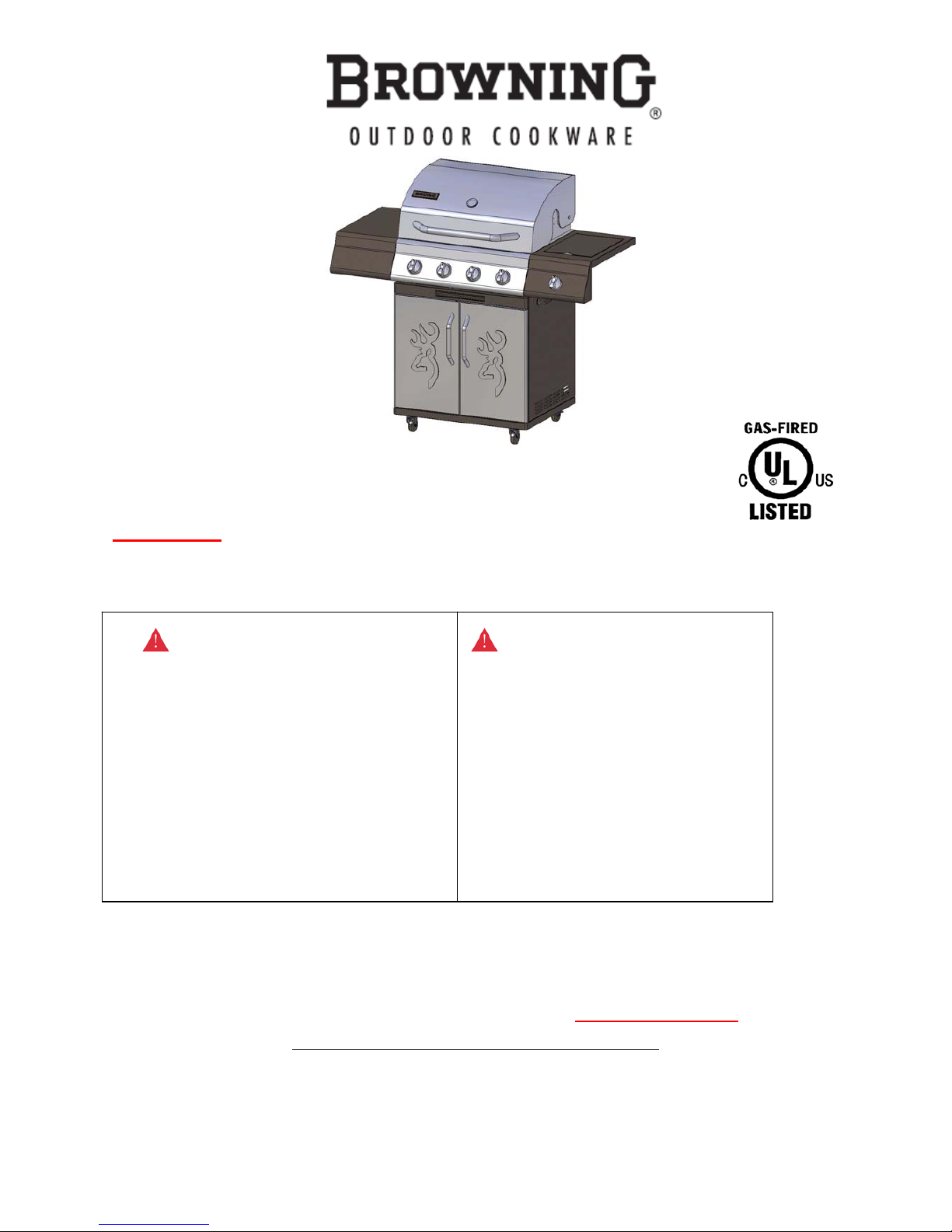
Owner’s Manual and Parts List
Item#: BR4GRILL
For 2518SLB-LPG
GAS FIRED BARBECUE GRILLS
*For questions, problems, missing parts, or obtaining replacement parts,
please contact Customer service at 1-800-650-2433
Monday thru Friday from 8:00 am to 5:00 pm MST.
Customer Service Address: PO Box 4057, Logan, Utah 84323
Distributed by Camp Chef
“Browning Trademarks Licensed by Browning”
Printed in China
DDANGER
If you smell gas:
1. Shut off gas to the appliance.
2. Extinguish any open flames.
3. Open the lid.
4. If the odor continues, keep away
from the appliance and
immediately call your gas
supplier or fire department.
WARNING
1. Do not store or use gasoline
or other flammable vapors
and liquids in the vicinity of
this or any other appliance.
2. An LP Tank not connected
for use should not be stored
in the vicinity of this or any
other appliance.
Warning:
Read the entire manual before attempting to assemble, adjust or use this
product. Please pay attention to Red Margin Troubleshooting Guide.

DEAR CUSTOMER,
TO BETTER SERVE YOU REGARDING QUESTIONS, MISSING
PARTS AND PROPER OPERATION OF YOUR GRILL, WE CAN
HELP FAST. PLEASE DO NOT RETURN YOUR GRILL,
JUST CALL OUR TRAINED CUSTOMER SERVICE DEPT AT
1-800-650-2433
.
AS A VALUABLE CUSTOMER YOU DESERVE PROPER
SERVICE.
THANK YOU,
CUSTOMER SERVICE

Table of Contents
Important Safety Information………………………………………………………….……………..1
Safety Tips…………………………………………………………………….………………………..3
Package Contents and Hardware List……...……………………………….………………………..4
Assembly Instructions…………………………………………….…………………...…………..…..6
Cooking with Gas…………………………………………………………………………..……...…16
Operating Instructions…………………………………………………………………...………...21
Cleaning and Maintenance……………………………………………………………...…………...25
Exploded View for LPG Model………………………………………………………...……………27
Replacement Parts List for LPG Model ..........…………………………………………………..…28
Warranty Program……......…………………………………………..……………..………………29
Troubleshooting Guide…....…………………………………………..……………..………………30

Important Safety Information
Page 1
IMPORTANT: Please carefully read this manual, especially the safety requirements, before
using your grill to ensure proper operation and reduce the risk of fire, burn hazard and other
injury.
General Safety Requirements:
1. The installation of this appliance must conform with local codes or, in the absence of local codes,
with either the National Fuel Gas Code, ANSI Z223.1/NFPA 54, or Natural Gas and Propane
Installation Code, CSA/CGA-B149.1.
2. This grill is intended for use outdoors and should not be used in a building, garage or any other
enclosed or covered area.
3. This outdoor grill is not intended for installation in or on recreation vehicles and/or boats.
4. A minimum clearance of 36 inches from combustible constructions to the sides of the grill and 36
inches from the back of the grill to combustible constructions must be maintained. This outdoor
cooking gas appliance must not be placed under overhead combustible construction.
5. The use of an electrical source requires that when installed, the grill must be electrically grounded
in accordance with local codes or, in the absence of local codes, with ANSI/NFPA 70, or the
Canadian Electrical Code, CSA C22.1. Keep electrical supply cords and the fuel supply hose
away from heated surfaces.
6. Inspect the hoses before each use for excessive abrasion or wear, or cuts that may affect safe
operation of the grill. If there is evidence of excessive abrasion or wear, or the hose is cut, it must
be replaced prior to the grill being put into operation. The replacement hose assembly must be
those specified by the manufacturer.
7. Keep your grill in an area clear and free from combustible materials, gasoline and other flammable
vapors and liquids.
8. DO NOT obstruct the flow of combustion and ventilation air to this appliance.
9. Keep the ventilation openings of the tank enclosure free and clear from debris.
10. Check all gas connections for leaks with a soapy water solution and brush. Never use an open
flame to check for leaks.
11. Never use charcoal in the grill.
12. Never use the grill in windy areas.
13. Never use the grill without the drip tray installed and pushed completely into the back of the grill.
Without the drip tray, hot grease and debris could leak downward and produce a fire hazard.
14. The pressure regulator for LP-gas grill is set for 11" water column (WC). Natural gas grill
provides a hose assembly which includes a quick-disconnect device but no pressure regulator. The
LP pressure regulator or the Natural gas hose assembly must be used. Replacement pressure
regulators and hose assemblies must be those specified in the part list.
15. Only a 20 lb LP-gas cylinder is allowed. The cylinder must be constructed and
marked in accordance with the Specifications for LP Gas Cylinders of the U.S.
Department of Transportation (D.O.T.) or the National Standard of Canada,
CAN/CSA-B339, Cylinders, Spheres and Tubes for Transportation of
Dangerous Goods; and Commission. A 20 lbs LP-Gas cylinder dimensions
are:

Important Safety Information
Page 2
16. The cylinder used must include a collar to protect the cylinder valve.
17. Do not store a spare LP-gas cylinder under or near this appliance.
18. Never fill the cylinder beyond 80 percent full.
19. If the information in “17” and “18” is not followed exactly, a fire causing death or serous injury
may occur.
20. The natural gas grill and its individual shutoff valve of must be disconnected from the gas supply
piping system during any pressure testing of that system at test pressures in excess of 0.5 psi (3.5
kPa).
21. The outdoor cooking gas appliance must be isolated from the gas supply piping system by closing
its individual manual shutoff valve during any pressure testing of the gas supply system at test
pressures equal to or less than 1/2 psi (3.5kPa).
22. CALIFORNIA PROPOSITION 65 WARNING: The burning of gas cooking fuel generates
some byproducts which are on the list of substances known by the State of California to cause
cancer, reproductive harm, or other birth defects. To reduce exposure to these substances, always
operate this unit according to the use and care manual, ensuring you provide good ventilation
when cooking with gas.
IMPORTANT: We urge you to read this manual carefully and follow the recommendations
enclosed. This will ensure you receive the most enjoyable and trouble-free operation of your new
gas grill. We also advise you retain this manual for future reference.
WARNING: Your grill has been designed to operate using only the gas specified by
manufacturer on the rating plate. Do not attempt to operate your grill on other gases. Failure to
follow this warning could lead to a fire hazard and bodily harm and will void your warranty.
WARNING: Make certain your LP (propane) tank is filled by a reputable propane dealer. An
incorrectly filled or an overfilled LP tank can be dangerous. The overfilled condition combined
with the warming of the LP tank (a hot summer day, tank left in the sun, etc.) can cause LP gas
to be released by the pressure relief valve on the tank since the temperature increase causes the
propane to expand. LP gas released from the tank is flammable and can be explosive. Refer to
your Owner’s Manual for more information concerning filling your LP tank.

Safety Tips
Page 3
z Never pull your grill. Always push it.
z Never move your grill while it is in operation or still hot.
z Always use a protected hand when cleaning the grid surface after the post-heating period and
when closing the propane tank valve.
z Use a covered hand during the grilling period.
z Wait until the burner box has completely cooled before reaching under to turn off the gas.
z Using an uncovered hand to turn off the LP tank valve without allowing the grill to cool down
could result in severe burns.
z Never operate your grill under overhangs, awnings or any covered or enclosed area.
z Never spray liquid on the grid area to control flare ups.
z To guard against possible grease fires getting out of control, never leave a grill unattended.
Grease fires can be severe and cause grill damage, property damage and bodily harm.
z Always turn off the control knob first, and then the propane gas supply tank.
z Never cover your grill while it is still warm.
z Position your portable grill away from direct wind.
z Do not store or use gasoline or other flammable substances in the vicinity of your gas grill.
z Never store a propane tank (whether full or empty) inside your home or living area.
z Before storing your tank, make sure that it has been turned to the “OFF” position.
z Should you store your grill indoors, be sure to close the tank valve, disconnect the hose from the
tank, remove the tank from the grill and store the tank outdoors.
z Make sure the grill hood is completely open before lighting your grill.
z When connecting or replacing any gas fittings, all joints must be sealed with an approved,
leak-proof sealing compound.
z Never use an open flame to test for gas leaks.
z When your grill is not in use, it is recommended that for child safety, you remove the control
knobs and store them indoors.
z Keep children away from the grill at all times.
z Never drill out any orifice or make any field alterations to your grill without receiving approval
from the manufacturer.
z Do not store flammable materials in any of the cabinets beneath the grill burner box or in the
vicinity of your grill.
z Be careful while handling any parts during assembly. It is strongly recommended that you protect
your hands with a pair of work mitts.
z At high temperatures stainless grids may discolor over time. When the grill is cool, wiping with a
wet towel and vegetable oil may remove and treat some of this effect. Some discoloration is
normal.

Package Contents and Hardware List
Page 4
Package Contents
P/N Description Qty. Diagrams
A Warming Rack 1
B Grid 2
C Flavor Step Tent 4
D Temperature Gauge 1
E Washer, Temperature Gauge 1
F Side Cooker Shelf Assembly
G 1/4-20 x 3/8” Screw
26
H 1/4-20 x 1 3/8” Screw 4
I Wind Shield 1
J Burner Box and Hood Assembly 1
K Drip Tray Support (L) 1
L Drip Tray Support (R) 1
M Rear Panel 1
N Bracket, Tank Ring
1
Package Contents and Hardware List
Page 5
P/N Description Qty. Diagrams
O Tank Ring
1
P Right Panel Assembly 1
Q Caster, Locking 2
R Door, Right 1
S Match Holder 1
T Screw 5/32-32 x 5/8” 1
U Caster 2
V Base Panel W/ Caster Bracket 1
W Drip Tray 1
X Door, Left 1
Y Beam 1
Z Left Panel Assembly 1
AA Knob 5
AB Side Shelf 1
Assembly Instructions
Page 6
Warning: The grill should be assembled and placed on a flat level surface.
Estimated Assembly Time: 40 minutes by two people.
Tools Required for Assembly: 1 Phillips screwdriver
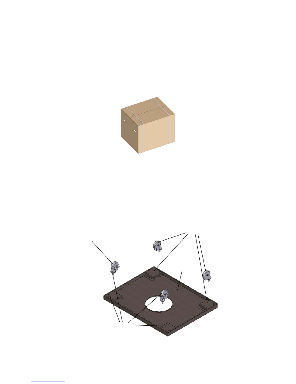
Step 1: Unpack carton. Compare the parts and hardware with the list and diagrams on pages 4 & 5.
Do not attempt assembly if any part is missing or damaged. Call customer service for a replacement at
1-800-650-2433.
Fig. 1
Step 2: Install Casters
Required: (4) Casters
Note: The casters tagged with “F” are for front use, “R” for rear use.
As shown in Fig. 2, screw in the four casters (Q and U). The casters (U) with “F” should be attached
to the two brackets in line with the door magnets. The letter tagged on the casters should be same as
the letter on the base. When this process is completed, turn the bottom panel (V) over. The door
magnets and the two casters with “F” mark should be at the front of the grill.
Fig. 2
Caster W/Brake
“F” Mark
Bottom Panel
“R” Mark
Assembly Instructions
Page 7
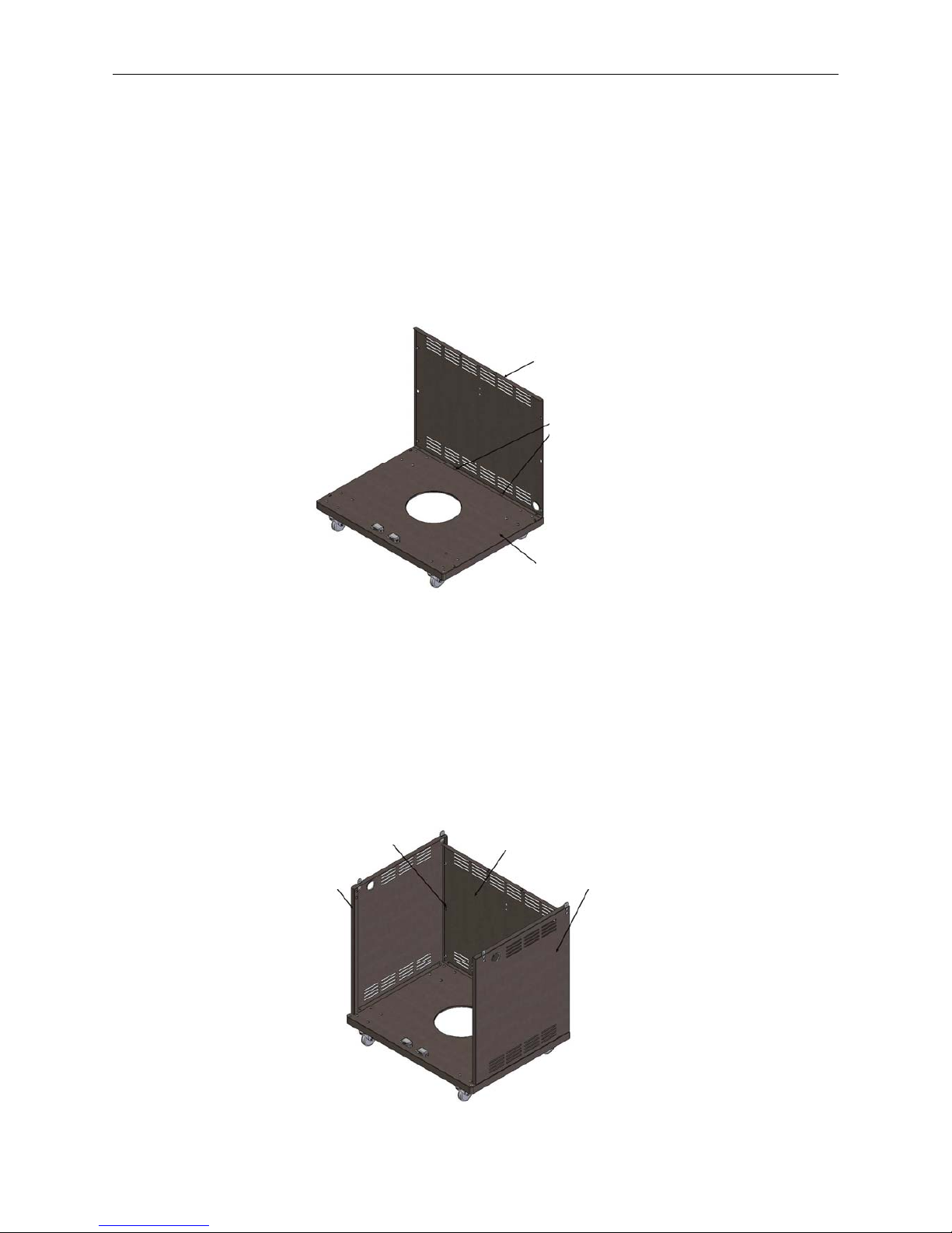
Step 3: Attach Rear Panel
Required: (2) 1/4–20 x 3/8” Screws (G), (1) Rear Panel (M)
Note: Do not tighten any cabinet screws completely. Leave at least one full turn on each. After
all the screws have been installed, go back and tighten them fully.
Align the tabs in the rear panel (M) with the square holes in the bottom panel (V), and then slide the
rear panel until the holes in the two panels are aligned. Insert the screws into the aligned holes. (See
Fig. 3)
Fig. 3
Step 4: Attach Side Panel
Required: (8) 1/4-20 x 3/8” Screws (G), (1) Left Side Panel (Z) and, (1) Right Side Panel (P)
Insert the “Tab A” in side panel (Z and P, Fig. 4) into the square hole in the rear panel (M) and push
down. Make sure the tab is locked in place. For each panel, there are four screws to connect the rear
panel and base, two in the rear and two inside the cabinet. Insert the screws into the aligned holes and
tighten them. The two screws inside the cabinet should be engaged first.
Fig. 4
Rear Panel
Two Tabs
Bottom Panel
Left Side Panel
Tab A
Rear Panel
Right Side Panel
Assembly Instructions
Page 8
Step 5: Attach Tank Ring applicable for 2518SLB-LPG
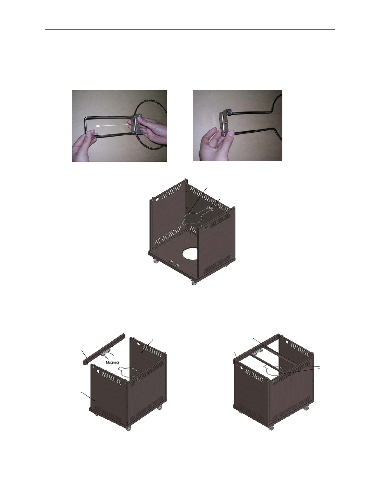
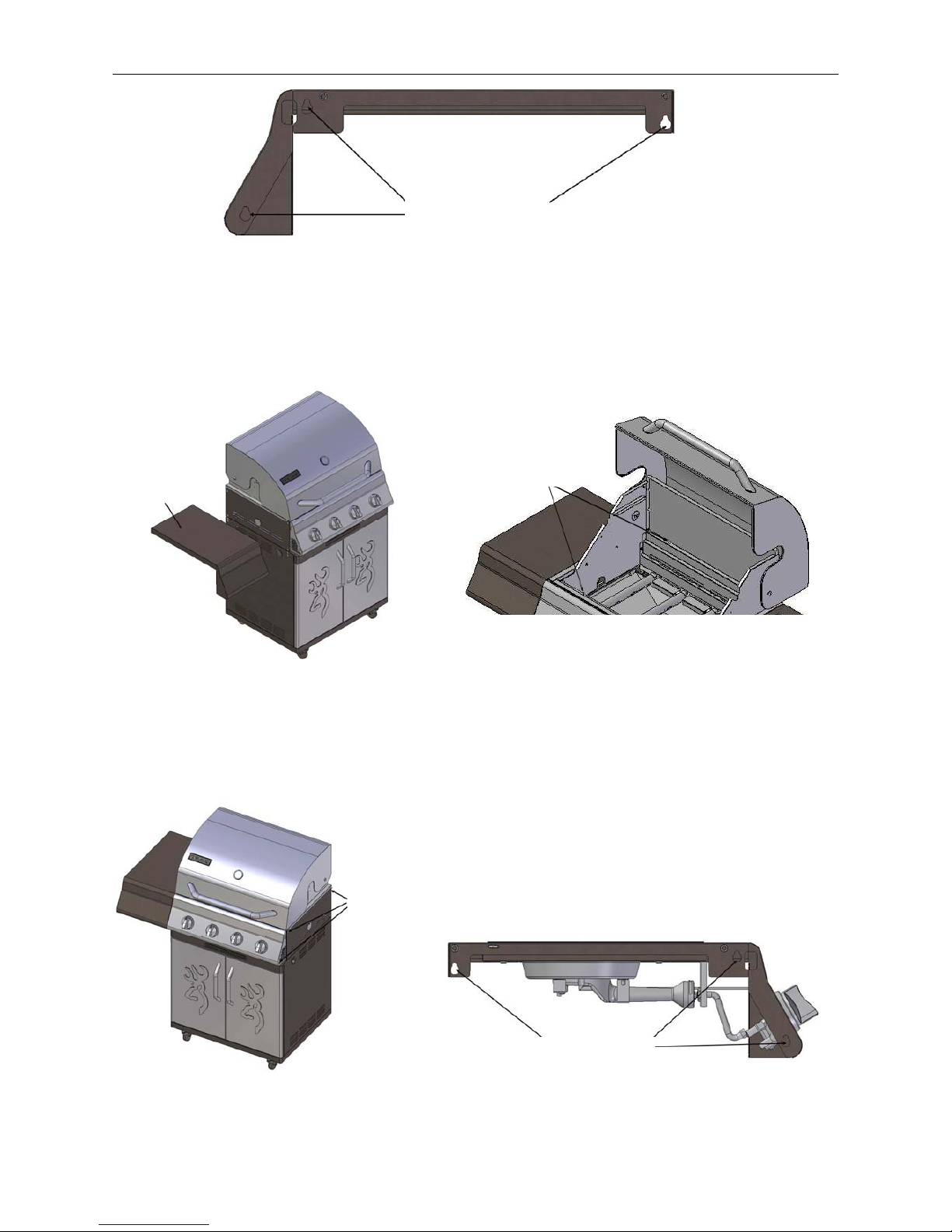
Required: (2) 1/4-20 x 3/8” Screws (G), (1) Tank Ring (O), (1) Ring Bracket (N)
Refer to Fig. 5a and Fig. 5b, slide the tank ring bracket (N) to the end of the tank ring (O) as shown.
Then align the holes in the ring bracket with rear panel (M), insert 1/4-20 x 3/8” (G) screws into the
holes from outside of grill, and then tighten completely. (See Fig. 6)
Fig. 5a Fig. 5b
Fig. 6
Step 6: Attach Beam & Drip Tray Supports
Required: (4) 1/4-20 x 3/8”Screws (G), (1) Beam (Y)
Fig. 7 Fig.8
Tank Ring
Ring Bracket
Left Side Panel
Beam
Screw Here
Drip Tray Support
Beam
Right Side Panel
Assembly Instructions
Page 9
Align the holes in the beam (Y) with magnets with both side panels (Z and P), insert 1/4-20 x 3/8” (G)
screws into the holes, and then tighten. (See Fig. 7)
Required: (2) 1/4-20 x 3/8” Screws (G), (2) Drip Tray Supports (K and L)
Note: The drip tray supports (K and L) should be installed with the open ends facing each other. Align
the drip tray supports with the slots in the beam (Y). Insert the two 1/4-20 x 3/8” screws (G) through
the holes in the drip tray support and the rear panel (M). (See Fig. 8).
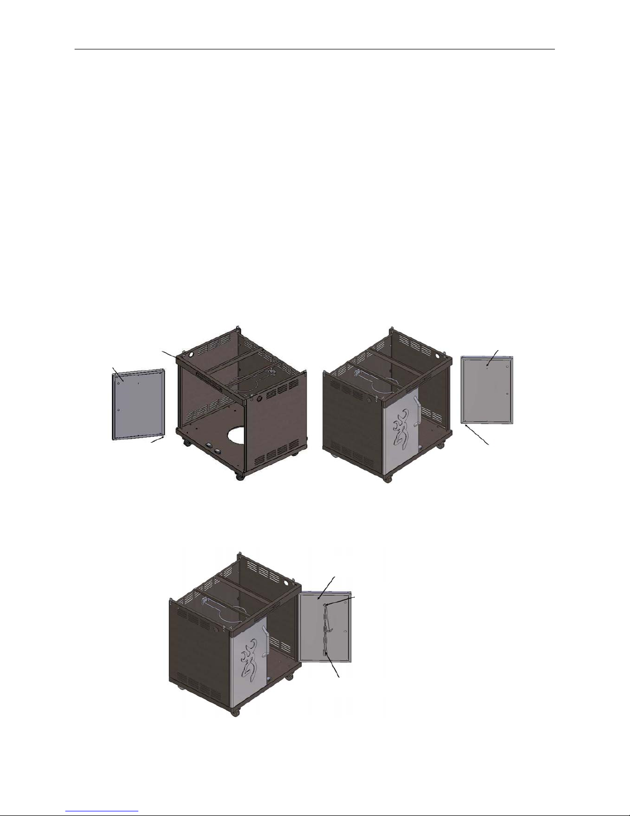
Step 7: Assemble doors
Required: (1) Left door (X), (1) Right Door (R), (1) Match Holder (S), (1) 5/32-32 x 5/8” Screw (T)
Before installing the doors, familiarize yourself with the door structure. The hinge is moveable. Insert
the upper hinge into the hole under the beam (Y). Push the spring through the square hole at the
bottom of the door until the hinge is aligned with the hole in the base panel, and then release. (See Fig.
9a).
Fig. 9a
Then install the match holder (S) in the right door (R) with screw 5/32-32 x 5/8” (T). (See Fig. 9b).
Fig. 9b
Left Door
Beam
Movable Hinge
Right Door
Movable Hinge
Right Door
Screw
Match Holder Chain
Assembly Instructions
Page 10
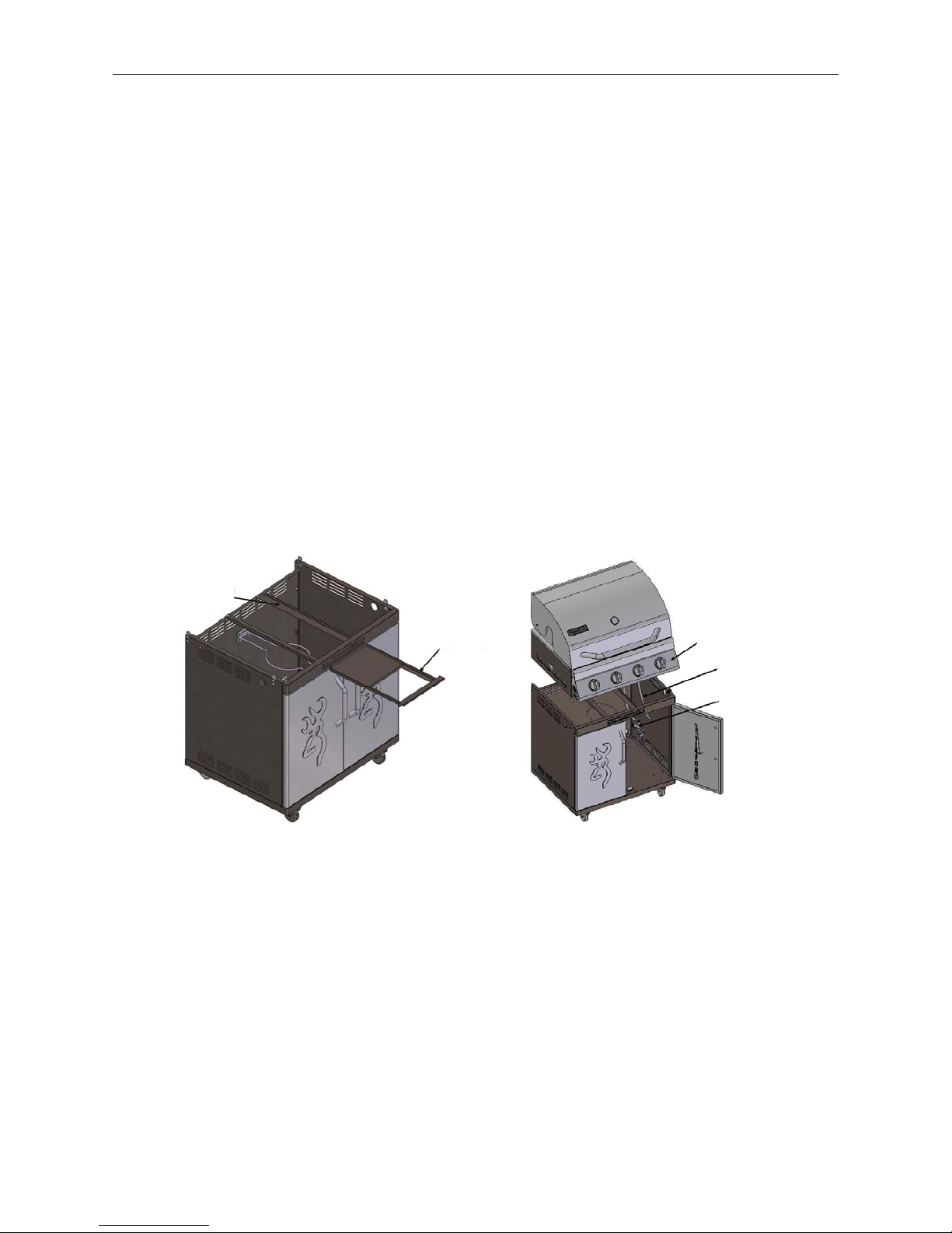
Step 8: Attach Drip Tray
Required: Drip Tray (W)
Slide the drip tray between the drip tray supports. (See Fig. 10).
Step 9: Mount the Burner Box onto the Cabinet
Required: (4) 1/4-20 x 3/8” Screws (G), (1) Burner Box (J), (1) Wind Shield (I)
Warning: The burner box is HEAVY. Before assembling the burner box to the grill cabinet,
make sure the cabinet is located in a solid and level place, and the wheels are locked. Two people
are required for a safe assembly.
a. Lock the two casters.
b. Take the pressure regulator (applicable only for LP gas grill) and side burner hose out from
under the control box (J). Then lift the burner box onto the cabinet, making sure that the flexible
gas lines are in the cabinet then position it on the cabinet by aligning the four tabs on top of the
cabinet with the holes in the burner box. (See Fig. 11)
Fig. 10 Fig. 11
Warning: Do not lift burner box from sides. We recommend holding the control box and the
rear panel of the burner box to avoid pinchin
g
fingers under the burner box.
c. Insert the 1/4-20 x 3/8” screws (G) into the two pre-drilled holes on each side of the burner box,
do not fully tighten screws until all screws have been installed. For LP gas grill, go to step d.
Drip Tray Support
Drip Tray
Burner Box
Side Burner Hose
LP Gas Pressure
Regulator
Assembly Instructions
Page 11
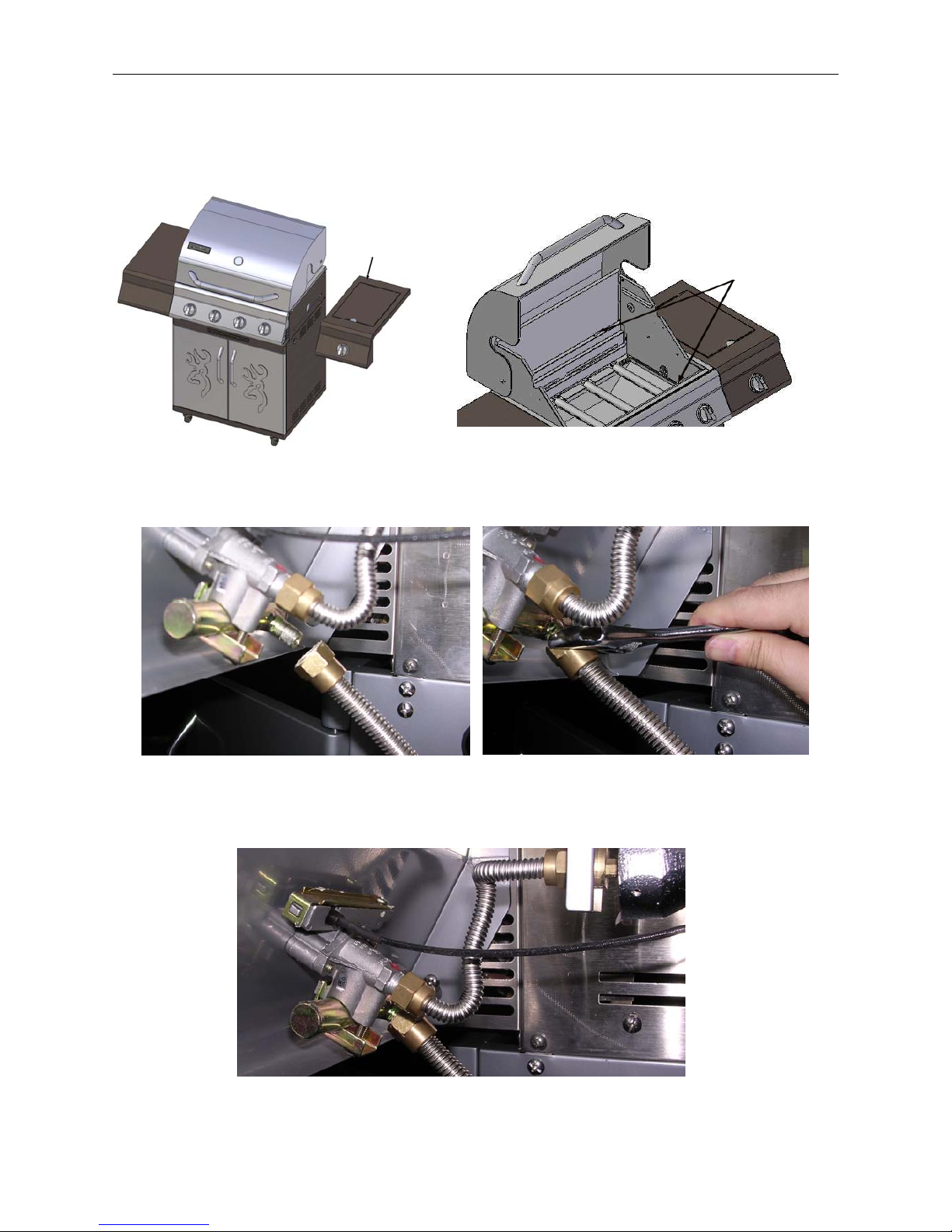
d. Place the side burner hose through the hole in the right side panel (P). See Fig. 12.
Fig. 12 Fig. 13
e. Wind shield (I) is required to be screwed in place as shown. Refer to Fig. 13, Fig. 14 and Fig. 15
to install the wind shield correctly.
Fig. 14 Fig. 15
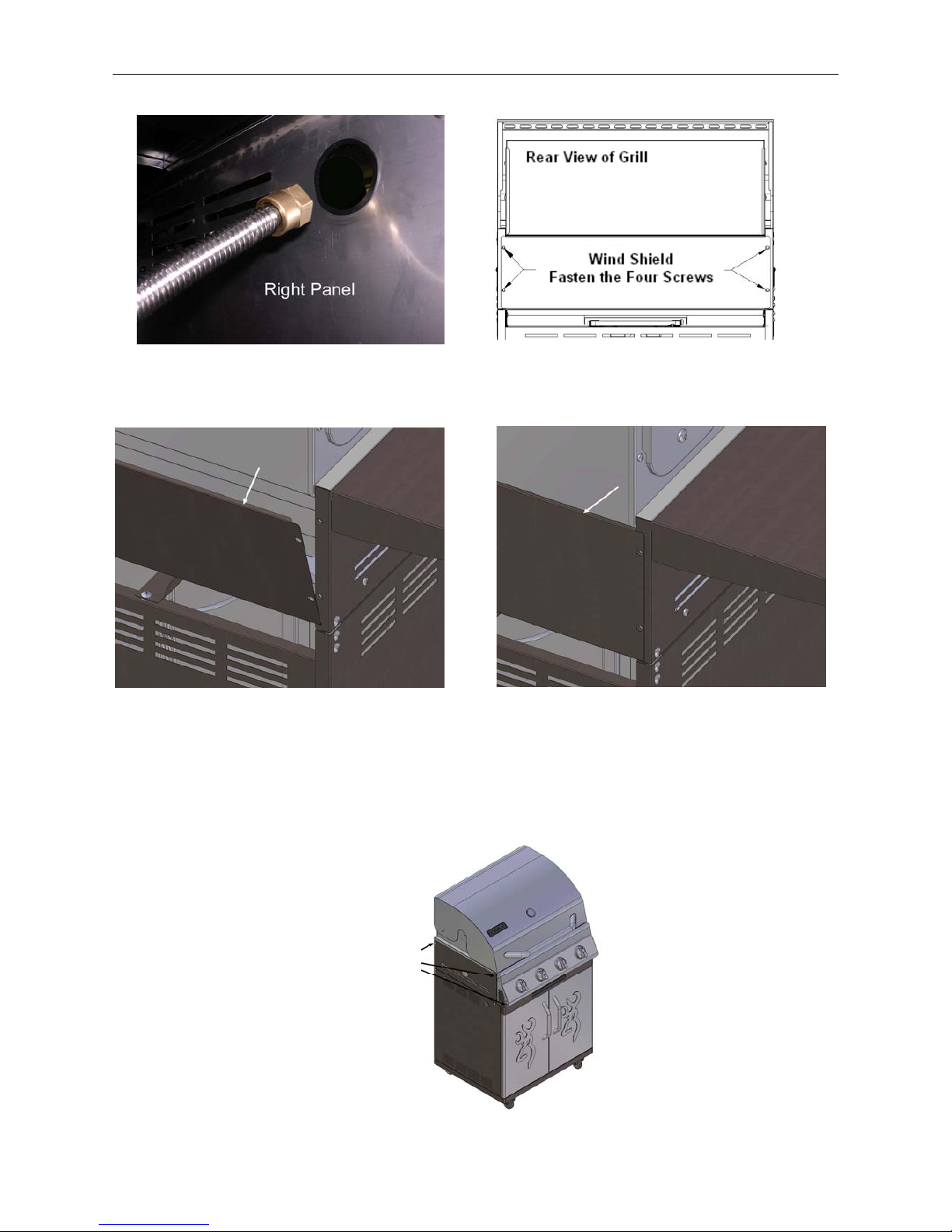
Step 10: Install Side Shelf
Required: (1) Side Shelf (AB), (2) 1/4-20 x 1 3/8" Screws (H)
a. Loosen two screws attached in the left panel of the burner box and one attached on the left panel
of the control box 3-4 turns (See Fig.16). Parts are not to be installed in this step. Just loosen the
three screws.
Fig. 16
This Side Up
Wind Shield
Wind Shield Upper Edge Position
Screw Here
Assembly Instructions
Page 12
Fig. 17
b. Align the side shelf holes (Fig.17) with the two screws in burner box side panel and the one in the
control box side panel, and push the shelf down to lock it in place. Then open the hood and use the
two 1/4-20 x 1 3/8" screws (H) to fasten the side shelf (AB) from inside the burner box. Refer to
Fig. 18 & Fig. 19(from inside the burner box). Then tighten the three screws loosened previously.
Fig. 18 Fig. 19
Step 11: Install Side Cooker Shelf
Required: (1) Side Cooker Shelf (F), (2) 1/4-20 x 1 3/8" screws (H)
Warning: The side cooker shelf assembly should be handled carefully.
a. Loosen the two screws attached in the right panel of
the burner box and one attached on the right panel of
the control box 3-4 turns (See Fig. 20). Parts are not
to be installed in this step. Just loosen the three
screws.
Fig. 20 Fig. 21
Assembly Holes
Screw Here
Side Shelf
Assembly Holes
Screw
Here
Assembly Instructions
Page 13
b. Align the side shelf holes (Fig. 21) with the two screws in burner box side panel and the one in
the control box side panel, and push the shelf down to lock it in place. Then open the hood and use
the two 1/4-20 x 1 3/8"screws (H) to fasten the side cooker shelf (F) from inside the burner box.
Refer to Fig. 22 & Fig. 23. Then tighten the three screws loosened previously.
Fig. 22 Fig. 23
c. Connect the side burner hose to the side burner manifold as shown in Fig. 24 and Fig. 25.
Fig. 24 Fig. 25
d. Make sure the side burner ignition wire is connected to the ignition pin and the ignition device.
See Fig. 26.
Fig. 26
Screw Here
Side Cooker Shelf
Assembly Instructions
Page 14
e. Align the nozzle within the side burner, refer to page 21 Fig. 34.
f. Check the distance between the ignition pin tip and the brass burner cover. The distance should be
0.1-0.2 inch. If the distance does not fall within this measurement, loose the ignition pin screws
and adjust the distance and then tighten the screw. (See Fig. 27).
Fig. 27
g. Position the side cooker grate. See Fig. 28
Fig. 28
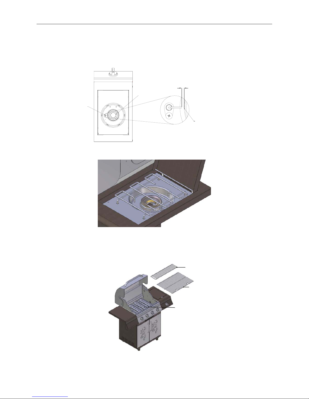
Step 12: Install the flavor step tents, grids and warming rack.
Referring to Fig. 29, position the four Flavor Step Tents, two cooking grids and the warming rack into
place.
Fig. 29
0.1-0.2 inch
Cover,
Brass Burner
Ignition
Pin
Cover,
Brass Burner
Warming Rack
Grids
Flaor Step Tents
Assembly Instructions
Page 15
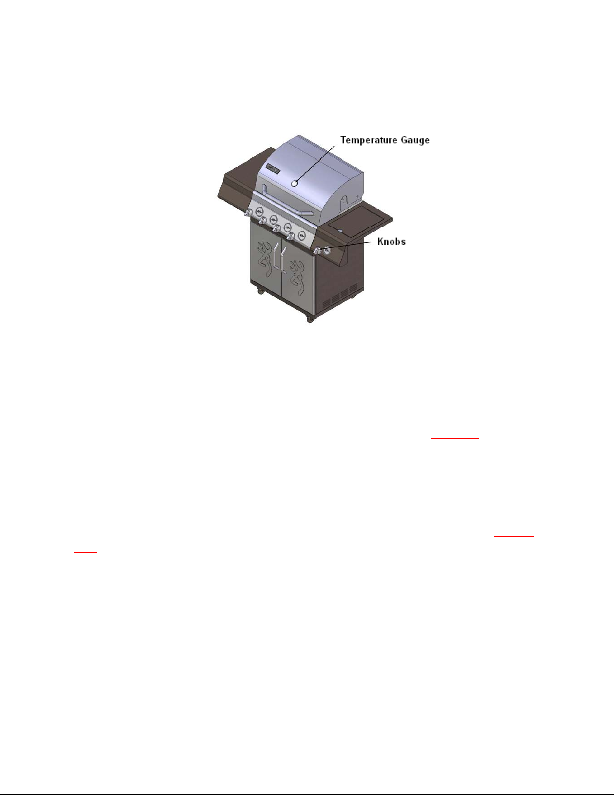
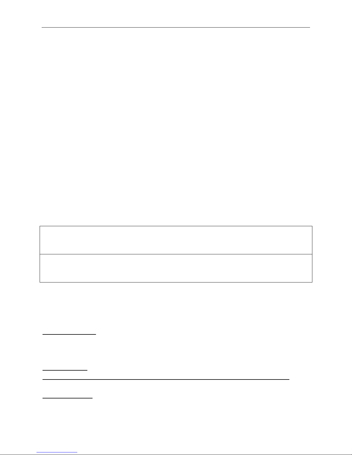
Step 13: Assemble temperature gauge and knobs
Required: (1) Temperature Gauge, (1) Washer, Temperature Gauge, (5) Knobs
a. Insert the temperature gauge in the hole as shown in Fig. 30; use the temperature gauge washer
and nut to install the temperature gauge.
Fig. 30
b. Insert knobs onto the valve stem. Make sure the knob arrows point upwards.
IMPORTANT
CHECK CLICK AND SPARK
After you complete your grill assembly, test your ignition system with the GAS OFF
. Check for
a click and spark when using your push in and turn knob ignition system.
For the side burner, a spark can be seen directly. For main burners, the ignition system
is positioned next to each burner inside the the burner box. A reflection of a spark or a spark
can be seen at the front of the inside of the burner box. Or you can place a mirror on the left
of the each main burner and see the spark and hear the click of the igniter. Be sure the GAS IS
OFF when you push in and turn the control knob. This will help assure a trouble-free ignition
when you turn on the gas.
Cooking with Gas
Page 16
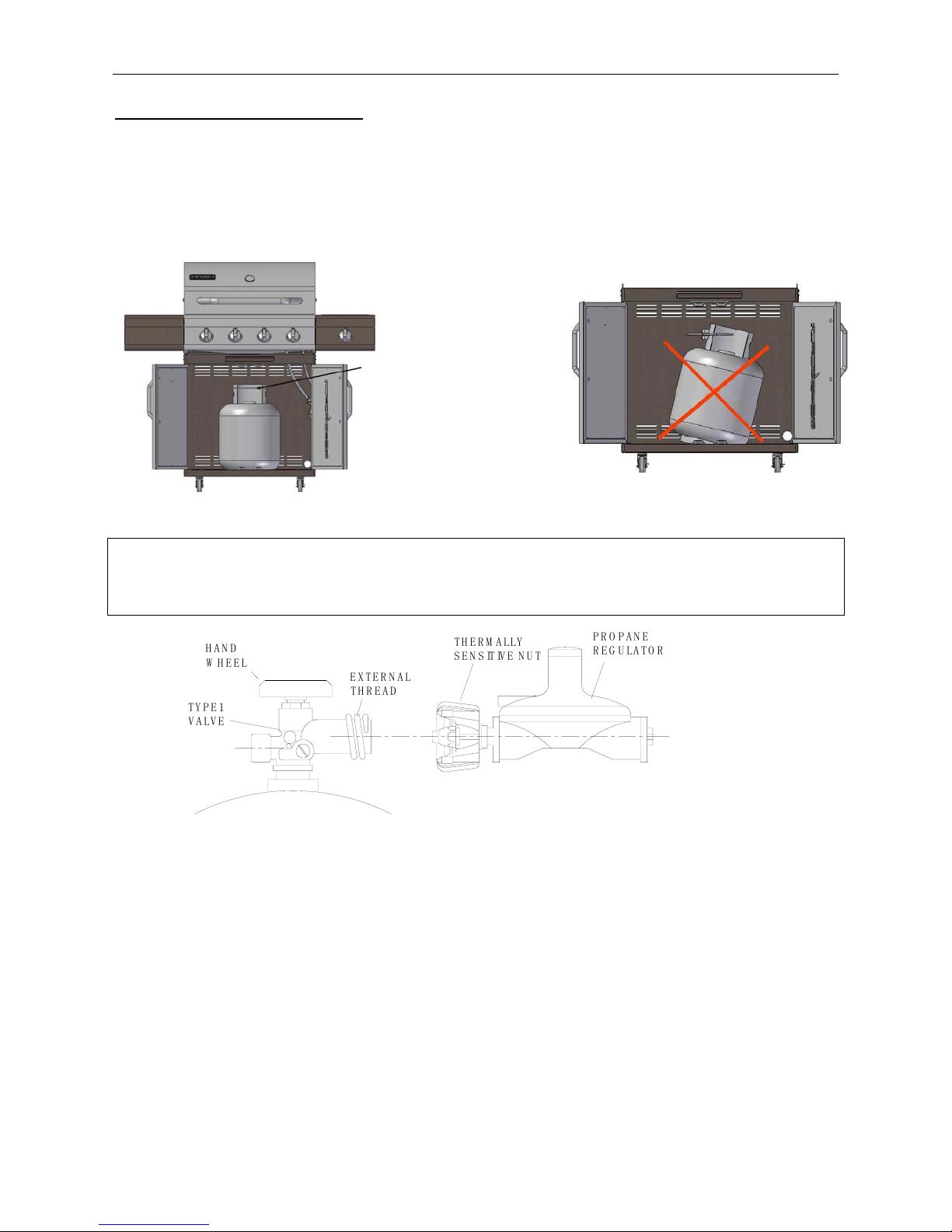
For Portable LP-Gas Connection
The cabinet has an opening in the bottom panel that allows a 20 lb. gas tank bottom flange to drop into
place. This will help to lock the tank. Before installing your gas tank, lift up the tank ring (as shown in
Fig. 31a). After positioning the tank in the opening, lower the tank ring to lock the tank. Use only 20
lb. gas tank (See LP Gas Safety Requirements for Additional Information). As shown in Fig. 31b, it
is unsafe to operate the grill if the gas tank is not vertical.
Fig. 31a Fig. 31b
WARNING: The Type I connective coupling (see Fig. 34) supplied with your grill must not be
replaced with a different type of grill/tank connection system. Removal will result in loss of
warranty, gas leakage, fire and severe bodily harm.
Fig.32
The propane tank valve connection supplied with this grill incorporates four important safe guards,
Hand Assembly, Hand Disassembly, Excess Flow Control and Temperature-Activated Shut-Off.
a. Hand Assembly:
1. Make certain the tank valve and all the appliance valves are in the “OFF” positions.
2. When connecting the regulator/burner valve assembly to the tank valve, turn the large plastic nut
clockwise until it stops.
3. Gas will not flow unless the plastic nut is completely connected.
4. HAND TIGHTEN ONLY.
b. Hand Disassembly:
1. Make certain the tank valve and all the appliance valves are in the “OFF” positions.
2. Turn the large plastic nut counterclockwise until it is disassembled.
HAND
WHEEL
TYPE1
VALVE
THERMALLY
SENSITIVE NUT
EXTERNAL
THREA
D
PROPANE
REGULATOR
Tank Ring
Cooking with Gas
Page 17
3. HAND OPERATION ONLY.
c. Excess flow Control and Low heat
The propane regulator assembly incorporates an excess flow device designed to supply the grill with
sufficient gas flow under normal conditions yet control excess gas flow.
Rapid changes in pressure can trigger the excess flow device providing a low flame and low
temperature. If the tank valve is turned open to allow gas flow while a burner valve is open, the surge
of pressure will cause the device to activate. The device will remain closed until the pressure is
equalized. This should occur within 5 seconds.
To ensure this does not cause difficulty in lighting the grill, follow these instructions:
1. Make sure all burner valves are “OFF”.
2. Open the tank valve and wait 5 seconds.
3. Light the burner one at a time following the lighting instructions listed on the control box and
page 21.
d. Temperature-Activated Shut-Off
The large plastic nut on the regulator assembly is designed in coordination with a check valve in the
tank valve to shut off the flow of gas when exposed to temperatures between 240-300 ℉.
In the event of a fire or hose break, one of the safeguards will function to control or stop the flow of
gas from the propane tank. Never attempt to use damaged equipment.
Important: Before the use of a fresh tank of gas, please check leakage around the connections
according to section ‘ Checking Gas Leaks ‘ on page 19 and make sure there is no leakage or
vapor accumulation in the cabinet. Make sure all openings around side walls are not blocked.
Important: Place dust cap on cylinder valve outlet whenever the cylinder is not in use. Only
install the type of dust cap on the cylinder valve outlet that is provided with the cylinder valve.
Other types of caps or plugs may result in leakage of propane.
Gas Requirements
The 2518SLB grill is set and tested at the factory for LPG only. No conversion to other kind of gas is
allowable.
LP Gas Regulator
This grill built for LP-Gas, the regulator supplied is set for 11 in. water column (WC) and is for use
with LP gas only. The factory-supplied regulator and hose must be used with a 20 lb. LP gas tank.
LP GAS System
Contact your gas supplier for a special regulator for bulk gas that fuels other appliances
Gas Consumption
Total gas consumption of this grill with the burner(s) on “HIGH”: Table 1 below.

Cooking with Gas
Page 18
Table 1
Burner Type BTU/HR
Main Burners 13250 x 4
Side Burner 13500 x 1
LP Gas Safety Requirement
For LP gas grills, the LP gas supply tank to be used must be:
(a) Constructed and marked in accordance with the Specifications for LP Gas Tanks of the U.S.
Department of Transportation (DOT) or the National Standard of Canada, CAN/CSA-B339
Cylinders, Spheres and Tubes for Transportation of Dangerous Goods; and Commission, as
applicable; and
(b) Provided with a listed Overfill Prevention Device (OPD).
(c) Provided with a tank connection device compatible with the connection for outdoor cooking
appliances.
The tank should be 12 inches in diameter and 18-1/2 inches tall and be equipped with a Type 1 fitting.
The tank supply system must be arranged for vapor withdrawal.
The tank used must include a collar to protect the cylinder valve.
Do not operate the gas grill indoors or in any enclosed area. If the gas grill is not in use, the gas must
be turned off at the supply tank. If the grill is to be stored indoors, disconnect the gas supply tank and
store the tank in an upright position in a cool, well-ventilated outdoor location away from your grill or
any other heat source.
When checking for gas leaks, do not use an open flame. Use a soapy water solution and apply it to the
pipe joints and fittings with a brush and check for bubbles. Check flexible hoses for cuts and wear that
may affect the safe operation of the grill. Only the factory supplied hose and regulator must be used.
Use only replacement regulator and hose assemblies specified by manufacturer.
Checking Gas Leaks
Before operating your grill, after refueling, check carefully to be certain that all connections are tight
and there are no gas leaks.
1. Make 2-3 ounces of leak solution by mixing liquid dishwashing soap with water.
2. Make certain all control knobs are in the “OFF” position.
3. Brush small amounts of the leak solution on all the fittings, and turn the gas on.
4. If bubbles appear, there is a leak. Proceed to step 5.
5. Turn the gas off, and tighten all connections.
6. Go back to step 1 to retest the fittings.
7. If bubbles continue to appear, turn the gas off. Contact customer service.
Warning: Never use a match or open flame for leak detection. Use of an open flame could result
in a fire, explosion and bodily harm.
IMPORTANT: When connecting or replacing any gas pipe or fittings, all joints must be sealed
with approved leak-proof sealing compound or plumbers tape.

Cooking with Gas
Page 19
Handling the Liquid Propane Tank Safely
Remember to handle your portable liquid propane tank carefully when you take it to your dealer for a
refill. Avoid dropping it or bumping it against sharp objects. Liquid propane tanks are sturdily
constructed, but a series of hard jolts could damage the container.
When transporting the tank to your local propane gas dealer, make sure the valve is closed tightly and
the protective cover is in place. Position the tank securely in an upright position so it will not roll
around your vehicle.
If you plan to make stops for shopping or errands, have your liquid propane tank filled at the last stop
before going home. Again, make certain the refilled tank is secure and in an upright position. When
you return home, remove the refilled tank from your vehicle. Never leave a portable liquid propane
tank inside a vehicle that may become overheated by the sun.
Your local liquid propane gas dealer will gladly offer you additional safety tips.
Storing the Liquid Propane Tank Safely
Whether you are between cross-country treks in your recreational vehicle or looking for a place to
keep the liquid propane tank to provide fuel for your outdoor grill, keep in mind some basic safety
rules about storing portable liquid propane tanks:
Do not store the tanks (whether full or empty) inside your home, the living area of an R.V., a garage,
basement or workshop. It is unlikely that liquid propane will leak from the tanks. If it should leak, the
fuel could be exposed to sparks from automobiles, power tools or other appliances. When storing or
transporting your LP tank, it must remain in an upright position. Never lay your LP tank down on its
side whether it is full or empty. Never store a spare tank under or near your grill.
CAUTION: Never transport or move your grill or grill tank without first closing the manual
valve on your liquid propane gas tank.
The best place to store a liquid propane tank is in a shady or protected spot outdoors, behind your
home or garage, or on a screened porch but where it is out of reach of children. Liquid propane will
not evaporate. It is in a strong, closed container. It will not lose any of its clean-burning heat content,
even if left outside year-round.
WARNING: When not connected to your grill, the LP gas tank must be stored in an upright
position in a cool, shady, well-ventilated, outdoor location away from your grill or any other
heat source. Failure to follow this warning could lead to tank valve damage, fire hazard and
personal injury.
Refilling a Propane Tank
It is extremely important that your LP tank be filled properly when you take it to be refilled. Be sure
to use a reputable LP dealer and observe how the tank is filled and at what capacity. An overfilled LP
tank can be dangerous.

Cooking with Gas
Page 20
The proper way to fill a tank is by weight. The empty tank should be placed on a scale. The scale
weights should be readjusted to a weight that would allow up to 80% of the total weight. The filling
operation must end once the tank is filled to 80% of its total capacity. If the tank is not completely
empty, the scale readjustment must be changed to consider the propane (LP) already in the tank.
WARNING: An LP (propane) tank is overfilled if it contains more than 80% of its total
capacity of propane (LP).
An incorrectly filled or an overfilled LP (propane) tank can be dangerous. If a tank is overfilled and
the weather causes the warming of the LP tank, (a hot day, tank left in sun or stored indoors) internal
pressure is created due to expansion of the propane which in turn may cause the LP gas to be released
through the pressure relief valve on the tank. The pressure relief valve is a safety device required on
20 lb. Propane tanks by the Department of Transportation to prevent a catastrophic tank failure due to
excessive pressure. LP gas released from the tank is flammable and can be explosive.
IMPORTANT: When connecting or replacing gas pipe or fittings, all joints must be sealed with
approved leak-proof sealing compound or plumbers tape. After making connections, check all
joints for leaks using a soapy water solution and a brush. See the instructions at page 19.
WARNING: Never use an open flame to test for gas leaks. Use of an open flame could result in a
fire, explosion and bodily harm.
Locating the Grill
This gas appliance is designed and certified for outdoor use only. Do not operate the grill inside a
building, garage, recreation vehicle, screened porch or any enclosed area. Keep the grill away from
windy areas, but keep the grill in a well-ventilated area. Do not obstruct the flow of combustion and
ventilation air around the grill.
Warning: Do not place the grill under overhead, unprotected combustible surfaces.
Clearance to Combustible Construction
A minimum clearance of 36
in. from the sides of the grill, and a minimum clearance of 36 in. from the
back of the grill to adjacent vertical combustible constructions must be maintained. However, the
manufacturer strongly suggests a 6 ft. clearance of the grill to combustible constructions.
Clearance to Noncombustible Construction
A minimum clearance of 36 in. from the back of the grill above the cooking surface to noncombustible
constructions is required to allow the grill hood to open completely. A minimum of 36 in. clearance to
the sides of the grill above the cooking surface to noncombustible constructions is recommend. The
grill can be installed directly next to noncombustible construction below the cooking surface.
Operating Instructions
Page 21
LO
HI
OFF
GRILL
Grill Lighting Instructions
Checking orifices alignment with burners
Orifices may shift during assembly and movement; therefore, check the orifices alignment with the
burners according to the following illustrations before lighting.
Orifice stud inside the air shutter
Orifice stud inside the air shutter
Fig. 33 Main Burner and Orifice Relationship
Orifice Position
Orifice must be in the
center of air shutter
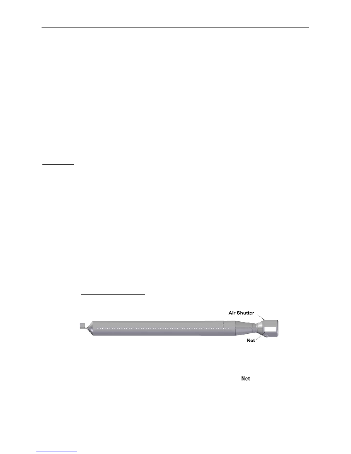
Fig. 34 Side Burner and Orifice Relationship
To Light the Main Burners & the Side Burner
1. Make sure the control knobs are in the “OFF” position.
2. Open the grill hood.
3. Make sure the drip tray is installed.
4. Open the tank valve.
5. Light each burner separately. Turning on two burner valves
together could trip the flow limiting device in the tank connection.
6. Push in and turn each control knob to the left and continue turning
from off to “HI” for 5 seconds while knob is depressed inward.
7. If the burner does not ignite within 5 seconds, immediately turn the control knob back to the
"OFF" position. Wait 5 minutes and repeat STEPS 6 and 7 up to 2 or 3 times.
8. If the burner still cannot be lit, refer to the Troubleshooting Guide.
Operating Instructions
Page 22
WARNING:
1. Make sure the hood is completely open each time you attempt to light the grill. Failure to
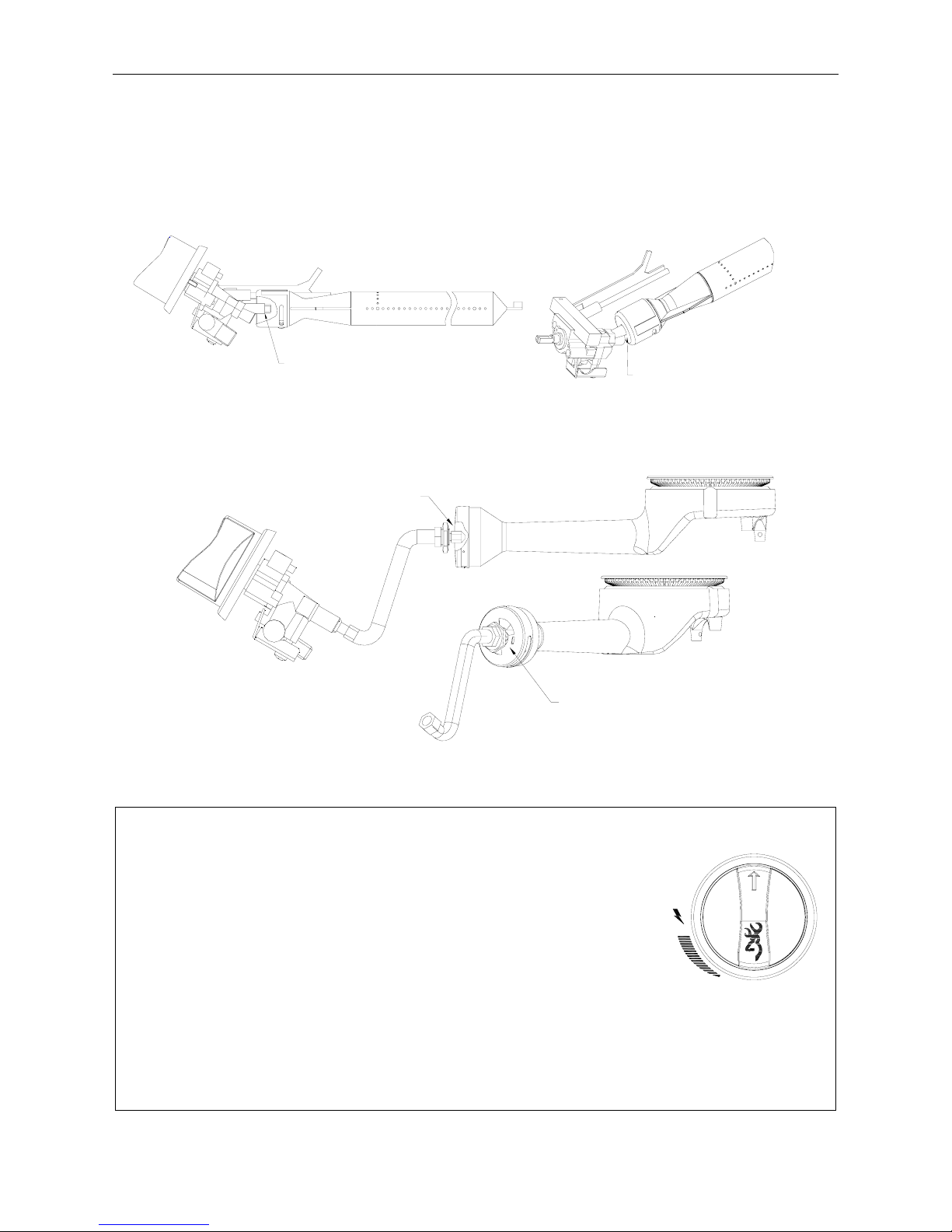
open the hood could lead to delayed ignition resulting in bodily harm.
2. This grill is equipped with a flame-observation hole in side panel. Wear protective mitts
before using the flame watch.
CAUTION: It is important to inspect the full length of the gas line hose. If it is evident there is
excessive abrasion or wear, or the hose is cut, the hose must be replaced prior to the appliance
being used.
If required, check your parts list for the proper replacement hose assembly. It will be necessary to
open the bottom door to fully inspect the hose.
Checking the Flame
Refer to the Fig. 35 below (side view of grill) check the flame after the grill is lit. Make sure you
have a stable, mostly blue flame.
Fig. 35
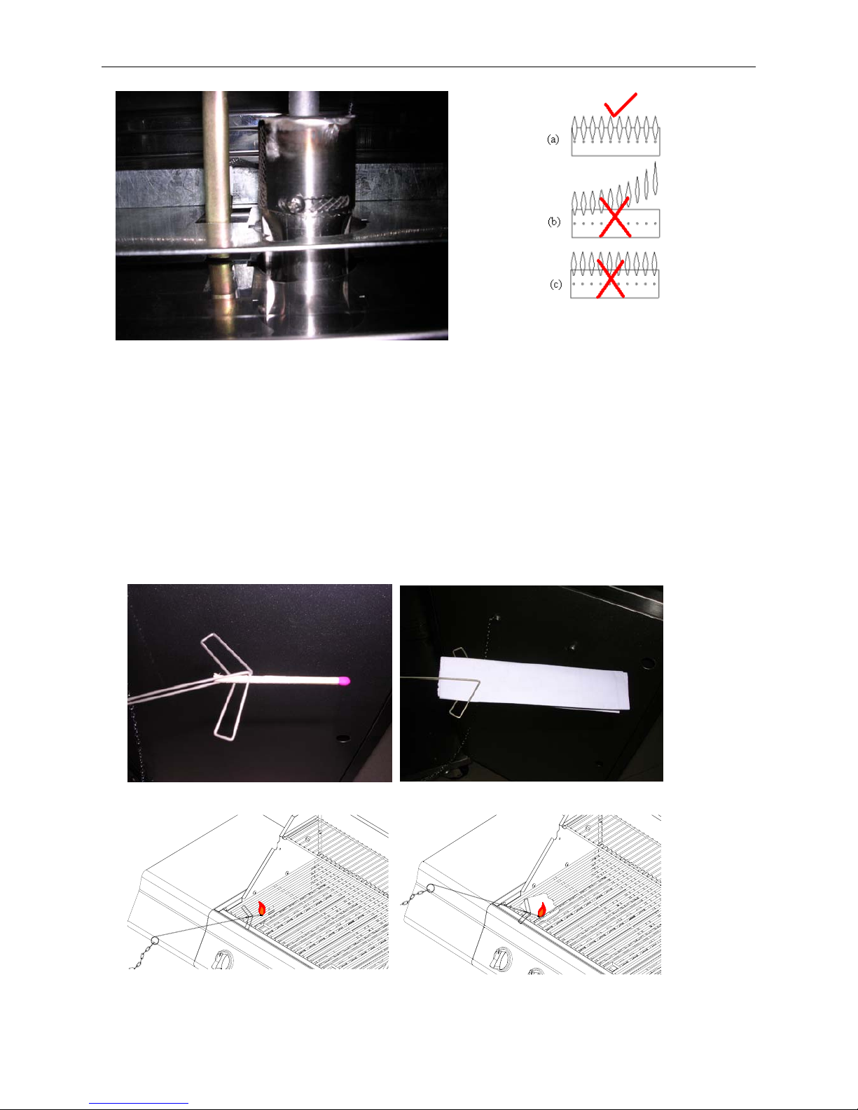
Air Shutter Adjustment
The gas burner shutters are adjusted at the factory for your convenience. The settings is:
(1) Full open for LP gas.
If you desire to fine tune your shutter adjustment (or if your flame is more yellow rather than blue),
please follow this procedure.
Warning: Do not touch burner after adjustments. The burner is hot.
a. The shutters are located on the end of the gas burners underneath the control box. See
Fig. 36.
b. Loosen the air shutter screw.
c. Light the burner to be adjusted.
d. With a protected, gloved hand, fine tune the air shutter until a stable, mostly blue flame
is observed through the flame observation holes and slots on each side of the burner box.
Acceptable flames are shown in Fig. 37.
e. Tighten the air shutter locking screw enough to hold the shutter in place.
f. Repeat procedure on other burners.
Operating Instructions
Page 23
Fig. 36 Air Shutter Fig. 37 Acceptable Flame only (a)
Match Lighting Instructions
Important: The hood must be open when match lighting any burner
1. Turn on gas supply
a. If portable, at the LP cylinder valve.
b. If permanent gas supply, at the manual gas shutoff valve.
2. Locate the flame observation holes on each side.
3. Open the right door to access the match clip with chain.
4. Attach either the match or paper to the clip (Fig. 38), light the match and insert it close to the
ports of the burner, and push and turn the depressed knob to the left to “HI” position.
Fig. 38 Match/Paper Lighting Illustration

Operating Instructions
Page 24
5. The center burner (if needed) can be lit from center grid by inserting the match clip into the front
side of flavor step tent. Light this burner before igniting both outside burners.
6. Depress burner valve for that burner and turn to high.
7. Observe that the burner has ignited. Remove the match and extinguish.
8. Repeat steps 2-6 for the next burner.
Breaking in Your Grill
When firing your grill for the first time, it is advisable to run the main burner(s) on “HI” for 20
minutes with the hood down, and then turn the main burners off. This tempers the grill.
Preheating Grill
It is extremely important that your grill be up to temperature before you begin using it. After lighting,
close the hood and preheat the grill on “HI” for 15 minutes. This preheating will ensure that the
cooking grid and grate are hot enough for proper grilling .
CAUTION: Do not cover the grids during the preheating period.
WARNING: Never leave a grill unattended to guard against possible grease fires getting out of
control. Grease fires can be severe and cause grill damage, property damage and bodily harm.
Open or closed hood for Grilling
Cooking with the lid open or closed is a matter of personal preference. Cooking with the lid closed is
recommended if you enjoy cooking at maximum “searing” temperatures. This method will also
produce more “flare up,” speed the cooking procedure and will give you a more robust, smoky,
outdoor flavor. If you prefer cooking slower with less flare up, we suggest the lid-open method.
We recommend always cooking with the lid CLOSED if you are in a windy area or colder climate.
Your 2518SLB Grill has been designed and constructed to give you maximum flexibility and cooking
performance. Be creative. Try different cooking methods on your grill to determine which suits your
needs best. There is no right or wrong way to cook, just different cooking styles. Get creative and
enjoy!
WARNING: Please remember this is an outdoor gas grill. Many areas of the grill generate
extreme heat. We have taken every precaution to protect you from the contact areas. However,
it is impossible to isolate all high-temperature areas. Therefore, use good judgment and a
certain degree of caution when grilling on this product. We suggest a covered, protected hand
during operation of grill. Do not move your grill when it is in operation or hot to the touch. Wait
until your unit is turned off and properly cooled down before moving it. Failure to follow this
warning could result in personal injury.
Post Heating
To keep the grates free of charred food remains, run the grill on “HI” for 15 minutes after cooking is
complete and food has been removed.
CAUTION: Do not cover the grill during the post heating period.
After post heating your grill, turn the control knobs to the “OFF” position.
Propane Tank Shut-Off
After the burner box cool down, the propane tank valve should also be closed. If you do not want to
wait for the burner box to cool, use a covered hand to turn off the propane tank valve.
WARNING: Do not attempt to turn off the LP tank valve without first covering your hand with
a protective mitt or allowing the grill to cool down. Failure to follow this warning could result in
a severe burn.
Cleaning and Maintenance
Page 25
Stainless Steel
2518SLB Stainless Gas Grill is mainly made of stainless steel. Stainless steel is non-rusting in certain
conditions; therefore, a cover and stainless steel cleaner should be used when the grill is not in use.
Wipe with WD40 or stainless steel cleaner on all non-cooking surfaces once a month.
Never clean the stainless steel when it is hot.
After initial grilling, certain areas of the grill (i.e. the vents, hood and burner box) may discolor. This
is a normal discoloration caused by the intense heat from the burners.
Specks of grease can gather on the surface of the stainless steel and get baked-on. These can usually
be removed with warm soapy water or a stainless steel cleaner. As a last resort a mild abrasive pad
could be used with a stainless cleaner. Use light pressure on the pad and always scrub in the direction
of the grain.
Do not use steel wool to clean the grill.
Do not use abrasive cleaners on the polished surface. Use caution when cleaning. Metal polish or a
mild chrome cleaner can be used to bring back luster and highlights. Naval Jelly can be used to
remove rust stains that occur from outside sources. Follow the Naval Jelly instructions carefully.
To touch up minor scratches in the stainless steel, sand the affected surface lightly with 160 dry grit
emery sand paper in the direction of the grain.
Burners
Burners are made of stainless steel and can be soaked in water and cleaned with a brass wire brush or
a stiff bristle brush. Check every port hole for clogs. Use a wire pin (smaller than the port) to clean
clogged ports. Do not enlarge any ports
. Make sure the burners are dry before installing them back to
the grill. See Fig. 39.
Fig. 39
Spiders and insects can nest inside the burners of this or any other grill, and cause the gas to flow from
the front of the burner. This is a very dangerous condition that could cause a fire to occur behind the
valve panel, thereby damaging the grill and making it unsafe to operate. Inspect the burners at least
once a year or immediately after any of the following conditions occur:
1. The smell of gas in conjunction with the burner flames appearing yellow.
2. The grill does not reach temperature.
Cleaning and Maintenance
Page 26
3. The grill heats unevenly.
4. The burners make popping noises.
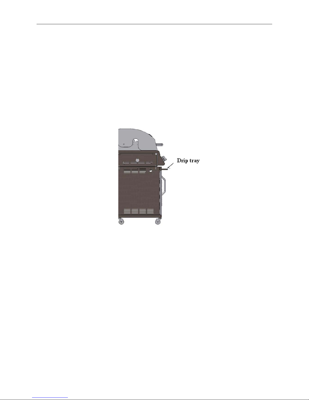
Drip Tray
The drip tray collects excessive grease runoff and fallen food particles.
Allow the tray and its contents to cool before cleaning. Slide the tray out and wipe it clean. Make sure
the tray is installed before using the grill.
It is highly recommended that you check the tray regularly to avoid any possibility of a grease fire;
however, most of the drippings will vaporize back into the cooked item giving you an outdoor grilled
flavor.
Fig. 40
Helpful Tips
Clean grill burner box
Clean grill burner box each season or after a grease build up with a non-toxic mixture of 3/4 cup
baking soda, 1/4 cup salt and 1/4 cup water. Spread paste on burner box surface, let stay for 24 hours
use a spatula to remove paste and wipe.
Gauging amount of LPG fuel
To gauge the amount of propane fuel in your gas tank, the grill must be in operation. Place your hand
at the top of the tank and slowly move down the side until the tank feels cool to the touch. This will
indicate the approximate amount of propane gas in your tank; if 3/4 empty, refill.
Do not use charcoal briquettes or any flammable material with your grill. Use of such material
will void your warranty and may lead to a fire, explosion and bodily harm.
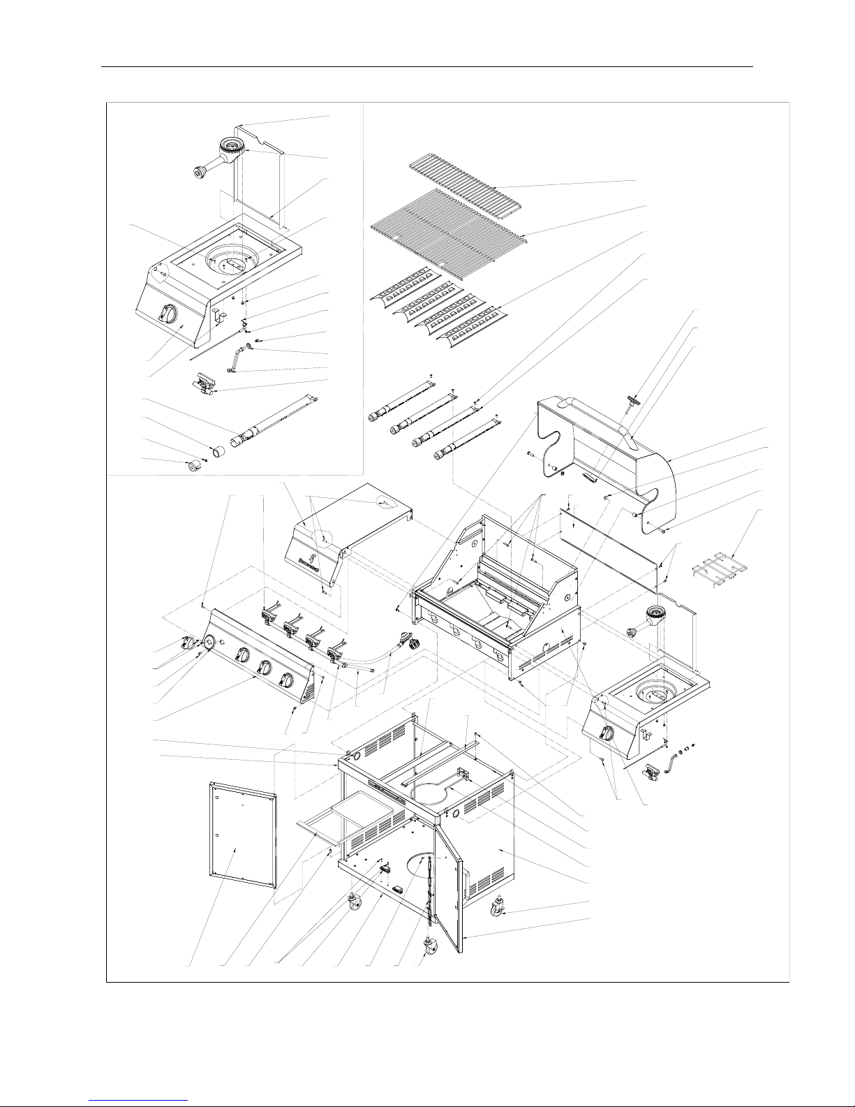
Exploded View for LPG Model
Page 27
1
2-B
3-N
4
5
8-B
9
10
11
28
29
28
30-B
31-B
32
28
28
28
28
32
33B-B
33A-B
35-B,28
36
38
39-B
40
41
42-B
4327
44-B
46-B
28,47-B
48,49-B
52-B
51-B
50
58-B
57
56-B
54
53-B
28
28
45
55
12-B
18
19
20
22
23-B
24-B
25-B
26-B
5-1
5-2
5-3
5-4
13-B
14
17
27
15-N
18a
6
7
8a
34-B,48
37-B,48
41a
Fig. 41
 Loading...