

Brother Z-8560A Owner's Manual

CONTENTS
1. PART NAMES AND SPECIFICATIONS ‥‥‥‥‥‥‥‥‥‥‥‥‥‥‥ 1
1-1 Part names1 ‥‥‥‥‥‥‥‥‥‥‥‥‥‥‥‥‥‥‥‥‥‥‥‥‥‥‥‥‥‥‥‥‥‥‥ 1
1-2 Specifications ‥‥‥‥‥‥‥‥‥‥‥‥‥‥‥‥‥‥‥‥‥‥‥‥‥‥‥‥‥‥‥‥‥‥‥ 1
1-3 Program list ‥‥‥‥‥‥‥‥‥‥‥‥‥‥‥‥‥‥‥‥‥‥‥‥‥‥‥‥‥‥‥‥‥‥‥ 2
2. PREPARATION ‥‥‥‥‥‥‥‥‥‥‥‥‥‥‥‥‥‥‥‥‥‥‥‥‥‥‥‥‥‥ 3
2-1 Installing the machine ‥‥‥‥‥‥‥‥‥‥‥‥‥‥‥‥‥‥‥‥‥‥‥‥‥‥‥‥‥‥‥ 3
2-2 Removing the machine head fixing bolt ‥‥‥‥‥‥‥‥‥‥‥‥‥‥‥‥‥‥‥‥‥‥‥‥ 4
2-3 Removing the BM support slide shaft fixing screw ‥‥‥‥‥‥‥‥‥‥‥‥‥‥‥‥‥‥‥ 4
2-4 Installing the auxiliary legs‥‥‥‥‥‥‥‥‥‥‥‥‥‥‥‥‥‥‥‥‥‥‥‥‥‥‥‥‥ 5
2-5 Checking the loop cutting‥‥‥‥‥‥‥‥‥‥‥‥‥‥‥‥‥‥‥‥‥‥‥‥‥‥‥‥‥ 5
2-6 Lubrication ‥‥‥‥‥‥‥‥‥‥‥‥‥‥‥‥‥‥‥‥‥‥‥‥‥‥‥‥‥‥‥‥‥‥‥‥ 6
2-6-1 Machine mechanism ‥‥‥‥‥‥‥‥‥‥‥‥‥‥‥‥‥‥‥‥‥‥‥‥‥‥‥‥‥ 6
2-6-2 Presser foot mechanism ‥‥‥‥‥‥‥‥‥‥‥‥‥‥‥‥‥‥‥‥‥‥‥‥‥‥‥ 7
2-7 Installing the cotton stand ‥‥‥‥‥‥‥‥‥‥‥‥‥‥‥‥‥‥‥‥‥‥‥‥‥‥‥‥‥ 7
2-8 Using the air unit ‥‥‥‥‥‥‥‥‥‥‥‥‥‥‥‥‥‥‥‥‥‥‥‥‥‥‥‥‥‥‥‥‥ 8
2-9 Pulley rotation direction ‥‥‥‥‥‥‥‥‥‥‥‥‥‥‥‥‥‥‥‥‥‥‥‥‥‥‥‥‥‥ 8
2-10 Threading belt loop ‥‥‥‥‥‥‥‥‥‥‥‥‥‥‥‥‥‥‥‥‥‥‥‥‥‥‥‥‥‥‥ 9
2-11 Detal on standard date setting ‥‥‥‥‥‥‥‥‥‥‥‥‥‥‥‥‥‥‥‥‥‥‥‥‥‥ 10
2-12 Checking the sewing data ‥‥‥‥‥‥‥‥‥‥‥‥‥‥‥‥‥‥‥‥‥‥‥‥‥‥‥‥ 10
2-13 Initializing the sewing data ‥‥‥‥‥‥‥‥‥‥‥‥‥‥‥‥‥‥‥‥‥‥‥‥‥‥‥‥ 11
3. PANEL OPERATION ‥‥‥‥‥‥‥‥‥‥‥‥‥‥‥‥‥‥‥‥‥‥‥‥‥‥‥ 12
3-1 Explanation of panel ‥‥‥‥‥‥‥‥‥‥‥‥‥‥‥‥‥‥‥‥‥‥‥‥‥‥‥‥‥‥‥‥ 12
3-2 Data setting methods ‥‥‥‥‥‥‥‥‥‥‥‥‥‥‥‥‥‥‥‥‥‥‥‥‥‥‥‥‥‥‥ 13
3-2-1 Setting the belt loop feeding-out length ‥‥‥‥‥‥‥‥‥‥‥‥‥‥‥‥‥‥‥‥‥ 13
3-2-2 Setting the bobbin counter ‥‥‥‥‥‥‥‥‥‥‥‥‥‥‥‥‥‥‥‥‥‥‥‥‥‥ 14
3-2-3 Clearing production counter ‥‥‥‥‥‥‥‥‥‥‥‥‥‥‥‥‥‥‥‥‥‥‥‥‥ 15
3-2-4 Setting the machine sewing speed ‥‥‥‥‥‥‥‥‥‥‥‥‥‥‥‥‥‥‥‥‥‥‥ 16
3-2-5 Loop feeding ‥‥‥‥‥‥‥‥‥‥‥‥‥‥‥‥‥‥‥‥‥‥‥‥‥‥‥‥‥‥‥‥ 17
3-2-6 Setting the program number‥‥‥‥‥‥‥‥‥‥‥‥‥‥‥‥‥‥‥‥‥‥‥‥‥ 18
3-2-6-1 Pattern selection mode‥‥‥‥‥‥‥‥‥‥‥‥‥‥‥‥‥‥‥‥‥‥‥‥19
3-2-7 Setting the X scale and Y scale ‥‥‥‥‥‥‥‥‥‥‥‥‥‥‥‥‥‥‥‥‥‥‥‥ 20
3-2-8 X and Y step feed ‥‥‥‥‥‥‥‥‥‥‥‥‥‥‥‥‥‥‥‥‥‥‥‥‥‥‥‥‥‥ 21
3-2-9 X-Y feed at real speed ‥‥‥‥‥‥‥‥‥‥‥‥‥‥‥‥‥‥‥‥‥‥‥‥‥‥‥‥ 22
3-2-10 X-Y movement ‥‥‥‥‥‥‥‥‥‥‥‥‥‥‥‥‥‥‥‥‥‥‥‥‥‥‥‥‥‥‥ 23
4. SEWING ‥‥‥‥‥‥‥‥‥‥‥‥‥‥‥‥‥‥‥‥‥‥‥‥‥‥‥‥‥‥‥‥‥‥ 24
4-1 Replacing needle ‥‥‥‥‥‥‥‥‥‥‥‥‥‥‥‥‥‥‥‥‥‥‥‥‥‥‥‥‥‥‥‥‥ 24
4-2 Threading the upper thread ‥‥‥‥‥‥‥‥‥‥‥‥‥‥‥‥‥‥‥‥‥‥‥‥‥‥‥‥ 25
4-3 Winding bobbin thread ‥‥‥‥‥‥‥‥‥‥‥‥‥‥‥‥‥‥‥‥‥‥‥‥‥‥‥‥‥‥ 26
4-4 Replacing the bobbin case and threading the thread ‥‥‥‥‥‥‥‥‥‥‥‥‥‥‥‥‥‥ 27
4-5 Sewing conditions and thread tension ‥‥‥‥‥‥‥‥‥‥‥‥‥‥‥‥‥‥‥‥‥‥‥‥ 28
4-5-1 Sewing conditions ‥‥‥‥‥‥‥‥‥‥‥‥‥‥‥‥‥‥‥‥‥‥‥‥‥‥‥‥‥‥ 28
4-5-2 Upper thread tension ‥‥‥‥‥‥‥‥‥‥‥‥‥‥‥‥‥‥‥‥‥‥‥‥‥‥‥‥‥ 28
4-5-3 Lower thread tension ‥‥‥‥‥‥‥‥‥‥‥‥‥‥‥‥‥‥‥‥‥‥‥‥‥‥‥‥ 28

4-5-4 Adjusting the thread tension spring ‥‥‥‥‥‥‥‥‥‥‥‥‥‥‥‥‥‥‥‥‥‥ 29
4-6 Trial sewing ‥‥‥‥‥‥‥‥‥‥‥‥‥‥‥‥‥‥‥‥‥‥‥‥‥‥‥‥‥‥‥‥‥‥‥ 30
4-6-1 Raising and lowering the presser foot ‥‥‥‥‥‥‥‥‥‥‥‥‥‥‥‥‥‥‥‥‥ 30
4-6-2 If the upper thread breakage codes (E-181, E-182) are displayed ‥‥‥‥‥‥‥‥‥ 31
4-7 Automatic sewing ‥‥‥‥‥‥‥‥‥‥‥‥‥‥‥‥‥‥‥‥‥‥‥‥‥‥‥‥‥‥‥‥‥ 32
4-7-1 If the belt loops run out during automatic sewing ‥‥‥‥‥‥‥‥‥‥‥‥‥‥‥‥ 32
4-7-2 If the machine stops during sewing ‥‥‥‥‥‥‥‥‥‥‥‥‥‥‥‥‥‥‥‥‥‥ 33
4-7-3 If the EMERGENCY STOP switch is pressed (E-100) ‥‥‥‥‥‥‥‥‥‥‥‥‥‥ 33
4-7-4 Resetting the belt loops ‥‥‥‥‥‥‥‥‥‥‥‥‥‥‥‥‥‥‥‥‥‥‥‥‥‥‥ 33
4-7-5 Removing an overlapping loop while in the sewing standby condition. ‥‥‥‥‥‥‥ 33
4-7-6 Stopping sewing when the presser foot is lowered ‥‥‥‥‥‥‥‥‥‥‥‥‥‥‥ 33
4-7-7 Raising and lowering the presser foot ‥‥‥‥‥‥‥‥‥‥‥‥‥‥‥‥‥‥‥‥‥ 33
4-7-8 If the upper thread breakage codes (E-181, E-182) are displayed ‥‥‥‥‥‥‥‥‥ 33
4-7-9 If an error code is displayed during sewing ‥‥‥‥‥‥‥‥‥‥‥‥‥‥‥‥‥‥‥ 33
4-7-10 Replacing the bobbin ‥‥‥‥‥‥‥‥‥‥‥‥‥‥‥‥‥‥‥‥‥‥‥‥‥‥‥ 34
4-7-11 Altering the production counter value ‥‥‥‥‥‥‥‥‥‥‥‥‥‥‥‥‥‥‥‥‥ 34
5. STANDARD ADJUSTMENT(MACHINE HEAD) ‥‥‥‥‥‥‥‥ 35
5-1 Tilting back the machine head ‥‥‥‥‥‥‥‥‥‥‥‥‥‥‥‥‥‥‥‥‥‥‥‥‥‥‥ 35
5-2 Adjusting the needle bar height ‥‥‥‥‥‥‥‥‥‥‥‥‥‥‥‥‥‥‥‥‥‥‥‥‥‥ 36
5-3 Needle bar lift stroke adjustment ‥‥‥‥‥‥‥‥‥‥‥‥‥‥‥‥‥‥‥‥‥‥‥‥‥‥ 37
5-4 Shuttle driver needle contact adjustment ‥‥‥‥‥‥‥‥‥‥‥‥‥‥‥‥‥‥‥‥‥‥ 38
5-4-1 First bar tacking ‥‥‥‥‥‥‥‥‥‥‥‥‥‥‥‥‥‥‥‥‥‥‥‥‥‥‥‥‥‥ 38
5-4-2 Second bar tacking ‥‥‥‥‥‥‥‥‥‥‥‥‥‥‥‥‥‥‥‥‥‥‥‥‥‥‥‥‥ 38
5-5 Needle to shuttle hook point gap adjustment ‥‥‥‥‥‥‥‥‥‥‥‥‥‥‥‥‥‥‥‥‥ 39
5-5-1 First bar tacking ‥‥‥‥‥‥‥‥‥‥‥‥‥‥‥‥‥‥‥‥‥‥‥‥‥‥‥‥‥‥ 39
5-5-2 Second bar tacking ‥‥‥‥‥‥‥‥‥‥‥‥‥‥‥‥‥‥‥‥‥‥‥‥‥‥‥‥‥ 39
5-6 Adjusting the shuttle hook thread guide ‥‥‥‥‥‥‥‥‥‥‥‥‥‥‥‥‥‥‥‥‥‥‥ 40
5-7 Adjusting the movable knife ‥‥‥‥‥‥‥‥‥‥‥‥‥‥‥‥‥‥‥‥‥‥‥‥‥‥‥‥ 40
5-7-1 First bar tacking ‥‥‥‥‥‥‥‥‥‥‥‥‥‥‥‥‥‥‥‥‥‥‥‥‥‥‥‥‥‥ 40
5-7-2 Second bar tacking ‥‥‥‥‥‥‥‥‥‥‥‥‥‥‥‥‥‥‥‥‥‥‥‥‥‥‥‥‥ 41
5-7-3 Replacing the movable knife and fixed knife ‥‥‥‥‥‥‥‥‥‥‥‥‥‥‥‥‥‥ 43
5-8 Adjusting the thread wiper ‥‥‥‥‥‥‥‥‥‥‥‥‥‥‥‥‥‥‥‥‥‥‥‥‥‥‥‥‥ 45
5-8-1 First bar tacking ‥‥‥‥‥‥‥‥‥‥‥‥‥‥‥‥‥‥‥‥‥‥‥‥‥‥‥‥‥‥ 45
5-8-2 Second bar tacking ‥‥‥‥‥‥‥‥‥‥‥‥‥‥‥‥‥‥‥‥‥‥‥‥‥‥‥‥‥ 45
5-9 Adjusting the width between the needles ‥‥‥‥‥‥‥‥‥‥‥‥‥‥‥‥‥‥‥‥‥‥ 46
6. STANDARD ADJUSTMENT (MECHANISMS) ‥‥‥‥‥‥‥‥‥‥ 48
6-1 Adjustments required when the belt loop length is changed ‥‥‥‥‥‥‥‥‥‥‥‥‥‥ 49
6-1-1 Adjusting fork bracket F ‥‥‥‥‥‥‥‥‥‥‥‥‥‥‥‥‥‥‥‥‥‥‥‥‥‥‥ 49
6-1-2 Adjusting slider base F ‥‥‥‥‥‥‥‥‥‥‥‥‥‥‥‥‥‥‥‥‥‥‥‥‥‥‥ 50
6-1-3 Adjusting the height of the slider bracket ‥‥‥‥‥‥‥‥‥‥‥‥‥‥‥‥‥‥‥‥ 50
6-1-4 Replacing the loop pressers ‥‥‥‥‥‥‥‥‥‥‥‥‥‥‥‥‥‥‥‥‥‥‥‥‥ 51
6-1-5 Adjusting the upper guide plates ‥‥‥‥‥‥‥‥‥‥‥‥‥‥‥‥‥‥‥‥‥‥‥‥ 51
6-2 Adjustments required when the belt loop width is changed ‥‥‥‥‥‥‥‥‥‥‥‥‥‥‥ 52
6-2-1 Adjusting channel ‥‥‥‥‥‥‥‥‥‥‥‥‥‥‥‥‥‥‥‥‥‥‥‥‥‥‥‥‥‥ 52
6-2-2 Adjusting the width adjustment plate ‥‥‥‥‥‥‥‥‥‥‥‥‥‥‥‥‥‥‥‥‥‥ 52
6-2-3 Adjusting the loop guide spring ‥‥‥‥‥‥‥‥‥‥‥‥‥‥‥‥‥‥‥‥‥‥‥‥ 53
6-2-4 During sewing ‥‥‥‥‥‥‥‥‥‥‥‥‥‥‥‥‥‥‥‥‥‥‥‥‥‥‥‥‥‥‥‥ 53

6-2-5 During sewing ‥‥‥‥‥‥‥‥‥‥‥‥‥‥‥‥‥‥‥‥‥‥‥‥‥‥‥‥‥‥‥‥ 54
6-3 Adjustments required when the belt loop thickness is changed ‥‥‥‥‥‥‥‥‥‥‥‥‥‥ 55
6-3-1 Adjusting joint sensor ‥‥‥‥‥‥‥‥‥‥‥‥‥‥‥‥‥‥‥‥‥‥‥‥‥‥‥‥‥ 55
6-3-2 Adjusting loop support T ‥‥‥‥‥‥‥‥‥‥‥‥‥‥‥‥‥‥‥‥‥‥‥‥‥‥‥‥ 55
6-3-3 Replacing the fork bracket and fork shafts (L and S) ‥‥‥‥‥‥‥‥‥‥‥‥‥‥‥ 56
6-3-4 Adjusting the fork shaft and the belt loop transfer height ‥‥‥‥‥‥‥‥‥‥‥‥‥‥ 58
6-3-5 Adjusting the air pressure for cleaning away belt scraps (during V cutting) ‥‥‥‥‥ 61
6-4 Adjusting the looseness of the belt loops ‥‥‥‥‥‥‥‥‥‥‥‥‥‥‥‥‥‥‥‥‥‥‥ 61
6-5 Adjusting the folding margin ‥‥‥‥‥‥‥‥‥‥‥‥‥‥‥‥‥‥‥‥‥‥‥‥‥‥‥‥‥ 62
6-6 Adjusting the folding ‥‥‥‥‥‥‥‥‥‥‥‥‥‥‥‥‥‥‥‥‥‥‥‥‥‥‥‥‥‥‥‥ 63
6-7 Changing the loop cutting shape (V cut or flat cut) ‥‥‥‥‥‥‥‥‥‥‥‥‥‥‥‥‥‥‥ 64
6-7-1 Adjusting the air pressure for cleaning away belt scraps (during V cutting) ‥‥‥‥‥‥ 64
6-8 Replacing the movable knife and fixed knife ‥‥‥‥‥‥‥‥‥‥‥‥‥‥‥‥‥‥‥‥‥‥ 65
6-9 Adjusting the belt loop and presser foot height ‥‥‥‥‥‥‥‥‥‥‥‥‥‥‥‥‥‥‥‥‥ 65
7. MAINTENANCE AND INSPECTION ‥‥‥‥‥‥‥‥‥‥‥‥‥‥‥‥‥ 66
7-1 Cleaning the rotary hook ‥‥‥‥‥‥‥‥‥‥‥‥‥‥‥‥‥‥‥‥‥‥‥‥‥‥‥‥‥‥ 66
7-2 Lubrication ‥‥‥‥‥‥‥‥‥‥‥‥‥‥‥‥‥‥‥‥‥‥‥‥‥‥‥‥‥‥‥‥‥‥‥‥ 66
7-3 Draining the oil ‥‥‥‥‥‥‥‥‥‥‥‥‥‥‥‥‥‥‥‥‥‥‥‥‥‥‥‥‥‥‥‥‥‥ 67
7-4 Cleaning the eye guard ‥‥‥‥‥‥‥‥‥‥‥‥‥‥‥‥‥‥‥‥‥‥‥‥‥‥‥‥‥‥‥ 67
7-5 Checking the needle ‥‥‥‥‥‥‥‥‥‥‥‥‥‥‥‥‥‥‥‥‥‥‥‥‥‥‥‥‥‥‥‥ 67
7-6 Cleaning the machine pulley ‥‥‥‥‥‥‥‥‥‥‥‥‥‥‥‥‥‥‥‥‥‥‥‥‥‥‥‥ 67
8. DIP SWITCH ‥‥‥‥‥‥‥‥‥‥‥‥‥‥‥‥‥‥‥‥‥‥‥‥‥‥‥‥‥‥‥‥ 68
8-1 Panel DIP switch functions ‥‥‥‥‥‥‥‥‥‥‥‥‥‥‥‥‥‥‥‥‥‥‥‥‥‥‥‥‥ 68
8-2 Main circuit board DIP switch functions ‥‥‥‥‥‥‥‥‥‥‥‥‥‥‥‥‥‥‥‥‥‥‥‥ 70
9. ERROR CODES ‥‥‥‥‥‥‥‥‥‥‥‥‥‥‥‥‥‥‥‥‥‥‥‥‥‥‥‥‥‥ 71
10. TROUBLESHOOTING ‥‥‥‥‥‥‥‥‥‥‥‥‥‥‥‥‥‥‥‥‥‥‥‥‥ 74
10-1 Machine Head ‥‥‥‥‥‥‥‥‥‥‥‥‥‥‥‥‥‥‥‥‥‥‥‥‥‥‥‥‥‥‥‥‥‥ 74
10-2 Mechanisms ‥‥‥‥‥‥‥‥‥‥‥‥‥‥‥‥‥‥‥‥‥‥‥‥‥‥‥‥‥‥‥‥‥‥‥ 79
11. OPTIONS ‥‥‥‥‥‥‥‥‥‥‥‥‥‥‥‥‥‥‥‥‥‥‥‥‥‥‥‥‥‥‥‥‥‥ 82
11-1 Hand set switch unit (S41639-001)‥‥‥‥‥‥‥‥‥‥‥‥‥‥‥‥‥‥‥‥‥‥‥‥‥‥ 82
11-2 Upper thread breakage detector assembly (S40520-009) ‥‥‥‥‥‥‥‥‥‥‥‥‥‥‥‥ 83
11-3 Belt loop slackener (S43632-001)
11-4 Loop setting sensor (S41959-001)‥‥‥‥‥‥‥‥‥‥‥‥‥‥‥‥‥‥‥‥‥‥‥‥‥‥ 85
11-5 Clipping disposal funnel assembly (S41906-001)
‥‥‥‥‥‥‥‥‥‥‥‥‥‥‥‥‥‥‥‥‥‥‥‥‥‥ 84
‥‥‥‥‥‥‥‥‥‥‥‥‥‥‥‥‥‥‥ 86

1. PART NAMES AND SPECIFICATIONS
1. PART NAMES AND SPECIFICATIONS
1-1. Part names
First bar tacking
Second bar tacking
1-2. Specifications
Cotton stand
Machine head
Operation panel
Loop unit
Power switch
Start switch
Control box
Air gun
Air unit
Max. sewing speed
Stitch length
No. of stitches
Rotary hook
Belt loop length
Belt loop width
Stitch interval
Belt loop thickness
Needle
Loop cutting
Power supply
Air pressure
Weight
Dimensions
2,100 spm
Bar tacking height 1 - 3 mm bar tacking width 7 - 22 mm
29 , 36 , 43 needle
Half rotation, double hook
48 - 78 mm (finished length)
9 - 16 mm (V cut) 9 - 20 mm (Flat cut)
40 - 70 mm
1 - 3 mm
DP×17NY#19 - 21
Flat cut, V cut (selectable)
3 phase 220V, 380V, 400V, 415V, 600VA
0.5MPa (5kg/cm
205kg (220V), 230kg (380V, 400V, 415V)
W 1100 mm L 837 mm H 1250 - 1530 mm
2
)
Table height
Stitch length
1000 - 1150 mm
0.1- 10mm
― 1 ―
BA S -705
1. PART NAMES AND SPECIFICATIONS
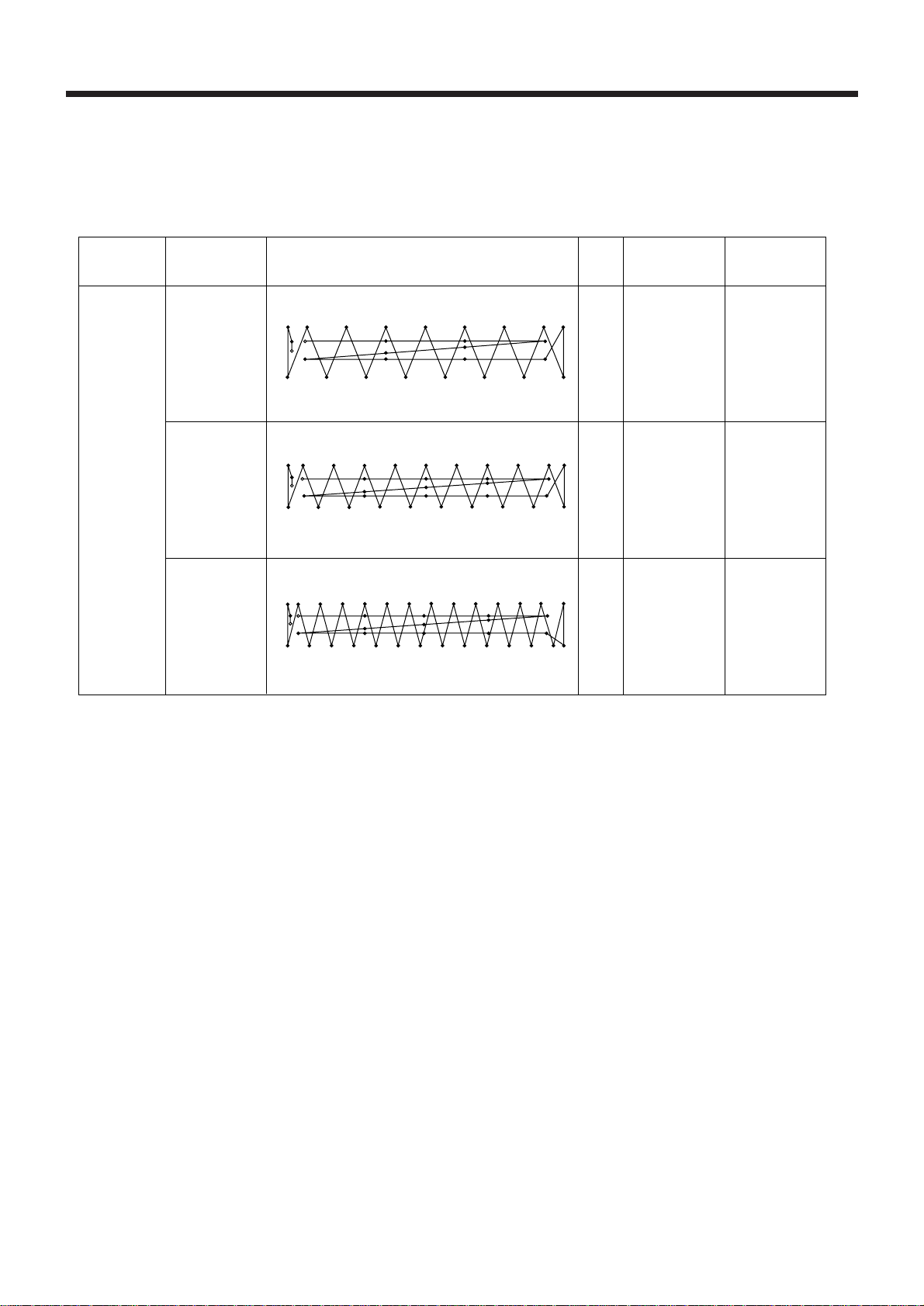
1-3.Program list
・The patterns given in the table below (pattern No. 1 - No. 3) are pre-programmed patterns which you
can select and use. (Any pattern can be selected and used as long as you make sure that it is within
the work clamp and feed plate in size.)
Standard bar
Use
Program No,
Sewing pattern
No.of
stitches
tacking length
Standard bar
tacking width
For denim
01
02
03
S
E
E
S
S
E
29
36
43
16mm
20mm
20mm
3mm
3mm
3mm
― 2 ―
BA S-705

2. PREPARATION
2. PREPARATION
CAUTION
●
Machine installation should only be carried
out by a qualified technician.
●
Contact your Brother dealer or a qualified
electrician for any electrical work that may
need to be done.
●
The sewing machine weighs more than 205
kg. The installation should be carried out by
two or more people.
●
Do not connect the power cord until installa
tion is complete, otherwise the machine may
operate if the start switch is pressed by mis
take, which could result in injury.
●
Be sure to connect the ground. If the ground
connection is not secure, you run the risk of
receiving a serious electric shock.
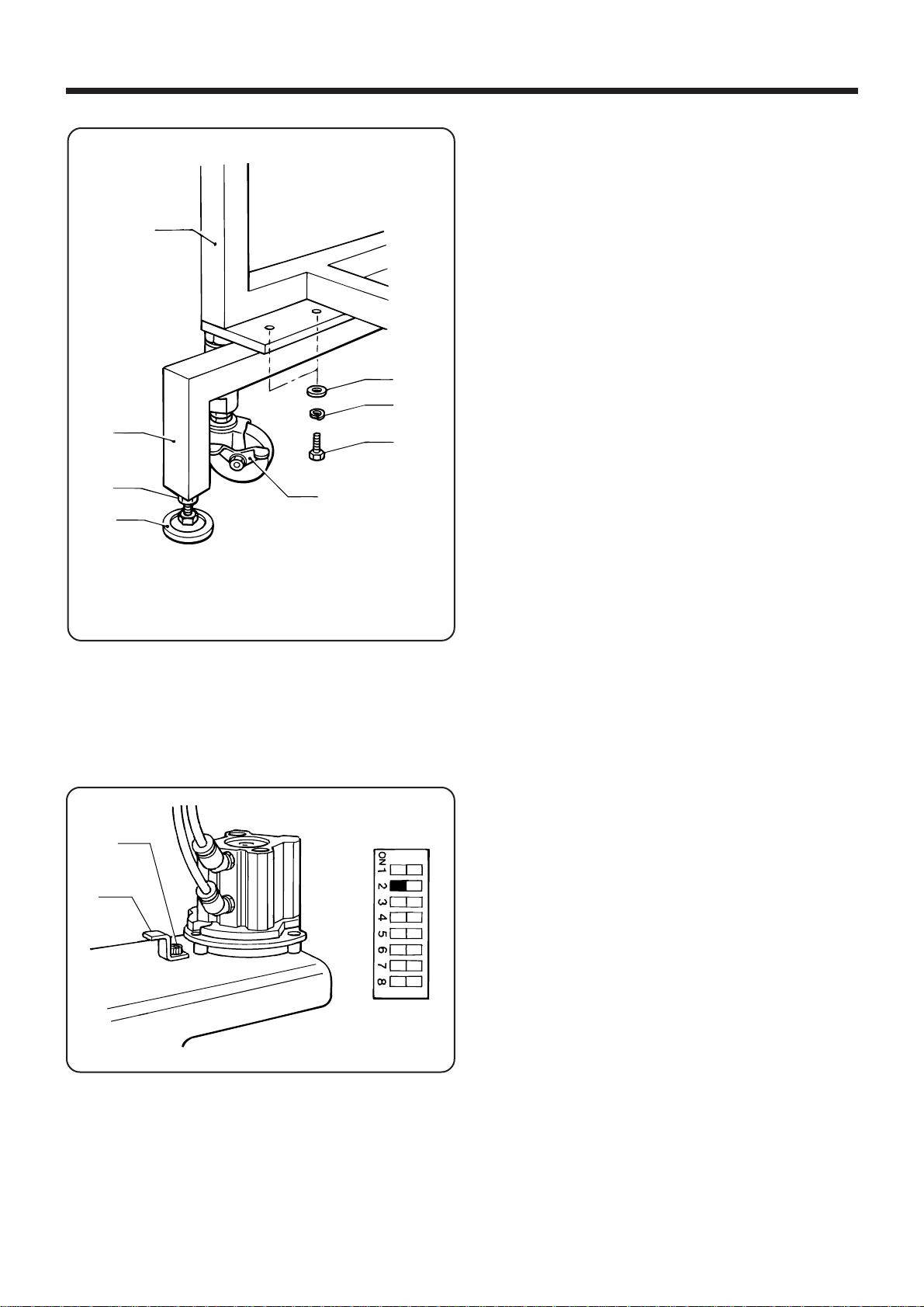
2-1. Installing the machine
e
●
Be sure to wear protective goggles and gloves
when handling the lubricating oil and grease,
so that they do not get into your eyes or onto
your skin, otherwise inflammation can result.
Furthermore, do not drink the oil or eat the
grease under any circumstances, as they can
cause vomiting and diarrhoea.
Keep the oil out of the reach of children.
●
Avoid setting up the sewing machine near
sources of strong electrical noise such as highfrequency welding equipment.
If this precaution is not taken, incorrect ma
chine operation may result.
1. Push the ON end of the lever q down to secure
the caster w.
2. The machine can be moved by pushing down the
OFF end lever q.
3. Loosen the nut e and turn the adjusting screw
r to adjust the height of the base.
NOTE:
After adjusting, securely tighten the nut e.
q
r
w
― 3 ―
BA S -705

2. PREPARATION
2-2.Removing the machine head fixing bolt
Remove the machine head fixing bolt q and nut.
NOTE: To ensure safety when moving the head,
q
firsttighten the machine head fixing bolt q
before moving the machine head.
2-3.Removing the BM support slide shaft fixing screw
q
Removing the BM support slide shaft fixing screw q.
NOTE: To ensure safety when moving the machine head, tighten the BM support slide shaft fixing screw q
before moving the machine head.
― 4 ―
BA S -705
2-4.Installing the auxiliary legs
q
t
r
2. PREPARATION
1. Remove the two auxiliary legs w which are secured
to leg frame q.
2. Re-install the two removed legs w as shown in the
illustration at left, and secure them with the bolts e,
spring washers r and flat washers t which were
removed before.
3. Loosen the nuts u (in two places) and turn the level
adjusters i to adjust the height of the casters y
above the floor.
NOTE: After adjusting, securely tighten the nut u.
w
u
i
y
2-5. Checking the loop cutting
q
w
e
No 1
NOTE: At the time of shipment from the factory, the V-
cutting cylinder is in the lock position (flat-end
cutting).
■Changing to V-shaped cutting
1. Remove the q, set the knife stopper w to the posi-
tion shown in the illustration at left, and then re-tighten
the bolt q.
2. Check that DIP switch No.1-2 on the panel is set to
“ON”.
― 5 ―
BA S -705

2. PREPARATION
2-6. Lubrication
CAUTION
●
T urn off the power switch before starting lubricating, otherwise the machine may operate if the start
switch is depressed by mistake, which could result in injury.
●
Be sure to wear protective goggles and gloves when handling the lubricating oil and grease, so that
they do not get into your eyes or onto your skin, otherwise inflammation can result.
Furthermore, do not drink the oil or eat the grease under any circumstances, as they can cause
vomiting and diarrhoea.
Keep the oil out of the reach of children.
NOTE ・Fill the machine with oil when the oil level is down to about one-third full in the oil sight glass.
If oil is not added and the oil drops below this level, there is the danger that the machine may seize
during operation.
・Be sure to let the machine operate for a while after adding the oil.
・Use only specified Brother oil (Nisseki Sewing Lube 10) for the machine oil.
2-6-1. Machine mechanism
1. Fill the arm-side oil tank with oil. 2. Fill the bed-side oil tank with oil.
3. Fill the oil tank at the side of the lower shaft module
base with oil.
― 6 ―
BA S -705
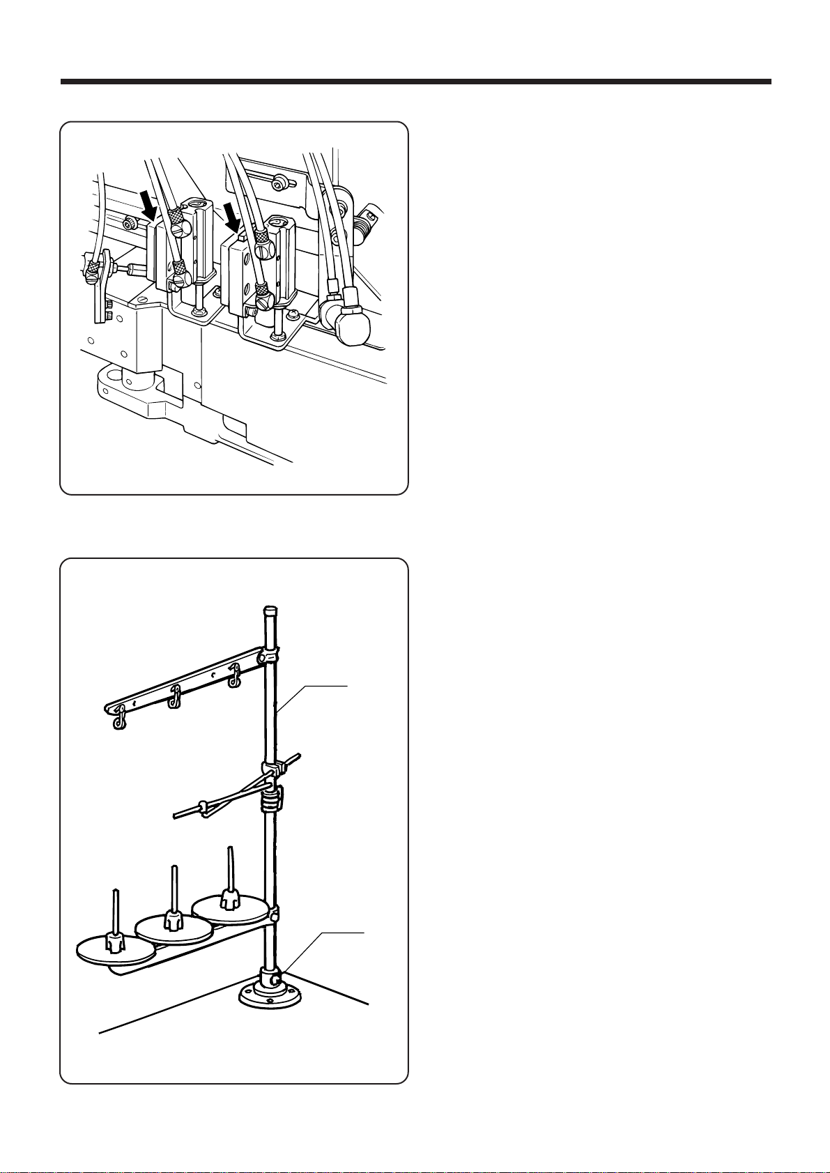
2-6-2.Presser foot mechanism
2. PREPARATION
Add 1 - 2 drops of sewing machine oil in the places
shown by arrows in the illustration.
2-7.Installing the cotton stand
Assemble the cotton stand q according to the directions given in the cotton stand instruction manual, and
then install it to the work table.
NOTE: Securely tighten the screw w so that the cotton
stand does not move.
q
w
― 7 ―
BA S -705
2. PREPARATION
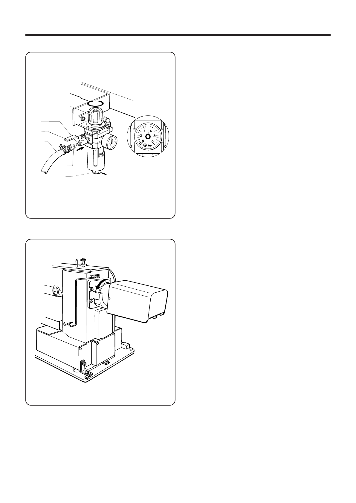
2-8.Using the air unit
r
w
t
q
e
y
1. Attach the air hose q to the air unit connector w
with the nut e.
2. Use air pressure at 0.49 MPa - 0.54 MPa (5 - 5.5
2
kgf/cm
Pull up the cap at the top of the air unit r and adjust
the pressure. After adjustment, push the cap down
to lock it.
NOTE: Every day, close the air cock t and push the
).
drain cock y to remove the water.
2-9.Pulley rotation direction
Turn on the power switch. Confirm that the pulley rotates in the direction of the arrow.
― 8 ―
BA S -705
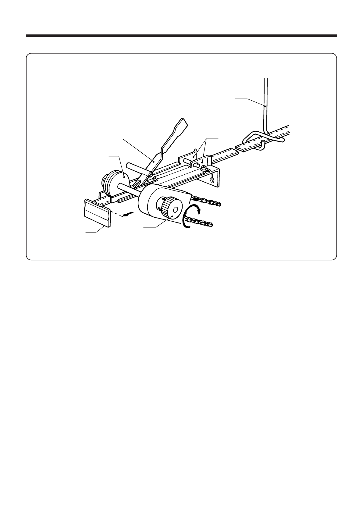
2-10. Threading belt loop
2. PREPARATION
q
e
t
Fixed knife
1. As shown in the figure above, thread a belt loop through the loop guide q, the channel guide w and the
actuator e in that order.
2. While holding the knob r, raise the feed roller t and insert the belt loop under the feed roller t.
3. Turn the knob r in the direction of the arrow to fit the belt loop tip to the fixed knife.
r
w
― 9 ―
BA S -705

2. PREPARATION
2-11. Detal on standard data settings
<BAS - 705 >
Main Ver. = 1.0
Panel Ver. = 1.0
X - Y Ver. = 1.0
Set home position
Press the start switch
AUTO MODE
Loop length
1st
bobbin counter
2nd bobbin counter
No loop
pass loop through the channel
1. Check that the air is being supplied.
* Refer to "2-7. Using the air unit" on page 8.
2. Turn on the power switch.
3. Press the START switch. The machine will then the
home position for the upper shaft X-Y feed and the
lower shaft.
NOTE:
・
Wait for at least 10 seconds after turning off
the power before turning it back on again. If
you do
"E-330"
・If there is no belt loop in position under the ac
tuator, the message shown at left will be dis played.
If this happens, refer to "2-10. Passing through
the belt loops" on page 9.
not wait long enough, the error code
will appear on the display.
2-12. Checking the sewing data
AUTO MODE
Production counter
1s t
bobbin counter
2nd bobbin counter
AUTO MODE
1s t
bobbin counter
2nd bobbin counter
Speed
AUTO MODE
2nd bobbin counter
Speed
Loop length
After the home position has been determined, press
the SELECT switches (▲ and ▼). The screen will then
start scrolling so that you can check the sewing data
settings.
― 10 ―
BA S -705
2. PREPARATION
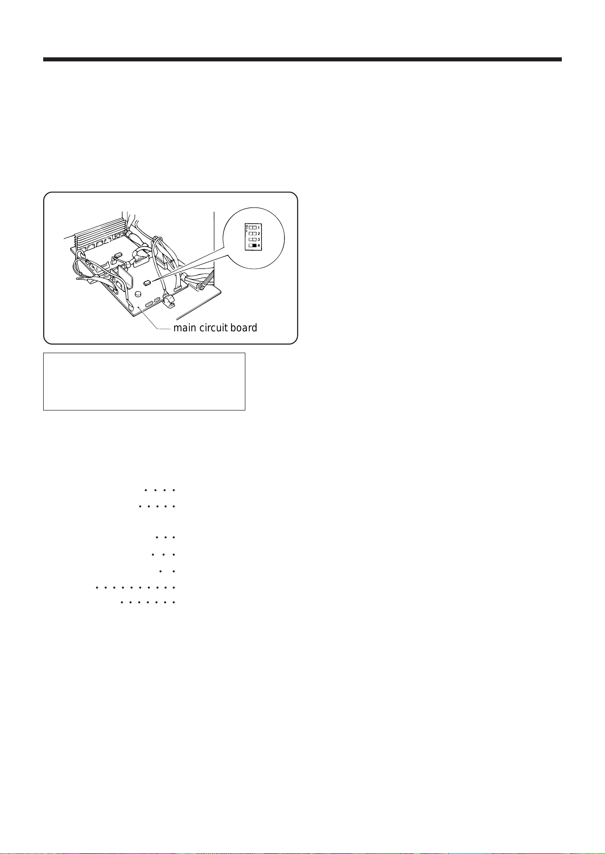
2-13.
Initializing the sewing data
・ Sewing data such as the bobbin thread counter and production counter settings are stored in a
memory which has a battery backup.
・If the power is not turned on for a long period of time (approximately three weeks or more), the
contents of the battery backup memory may become corrupted, causing the error code "E-160" to
appear on the display when the machine is turned on.
If this happens, initialize the sewing data by following the procedure below.
Initialized
Check sewing data
main circuit board
1. Turn off the power switch.
2. Open the control box cover and set DIP switch No. 4
on the main circuit board to ON.
(Refer to "8-2. Main circuit board DIP switch funtions"
on page 68.)
3.
Turn on the power. After approximately 2 seconds
have passed, "Initialized" will appear on the display.
4.
Turn of f the power switch, set DIP switch No. 4 on
the main circuit board to ”OFF”, and then close the
control box cover.
■ Sewing patterns 129 needle
■ Xscale・Yscale 100% for all sewing
○○○○
○○ ○○○
patterns
■Production counter 0
■1st bobbin counter 300
■2nd bobbin counter 300
■Speed
■Loop length 100
○○○○○○○○○○
○○○○○○○
○○○
○○○
○○
2100 spm
NOTE:
When the backup initialization is carried out, the
・
sewing data values will be reset to the values
shown at left.
― 11―
BA S -705
3. PANEL OPERATION
q!0r
3. PANEL OPERATION
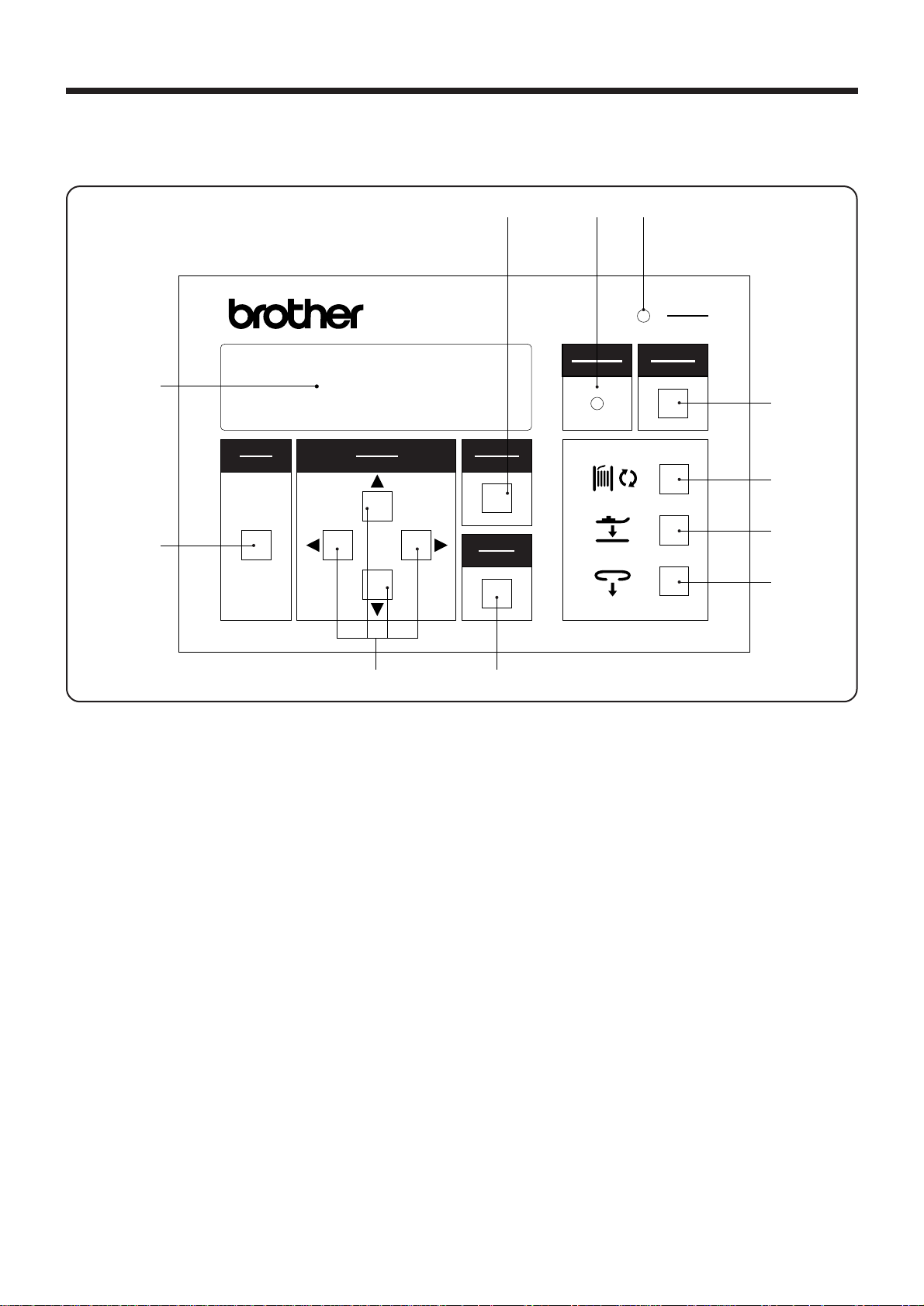
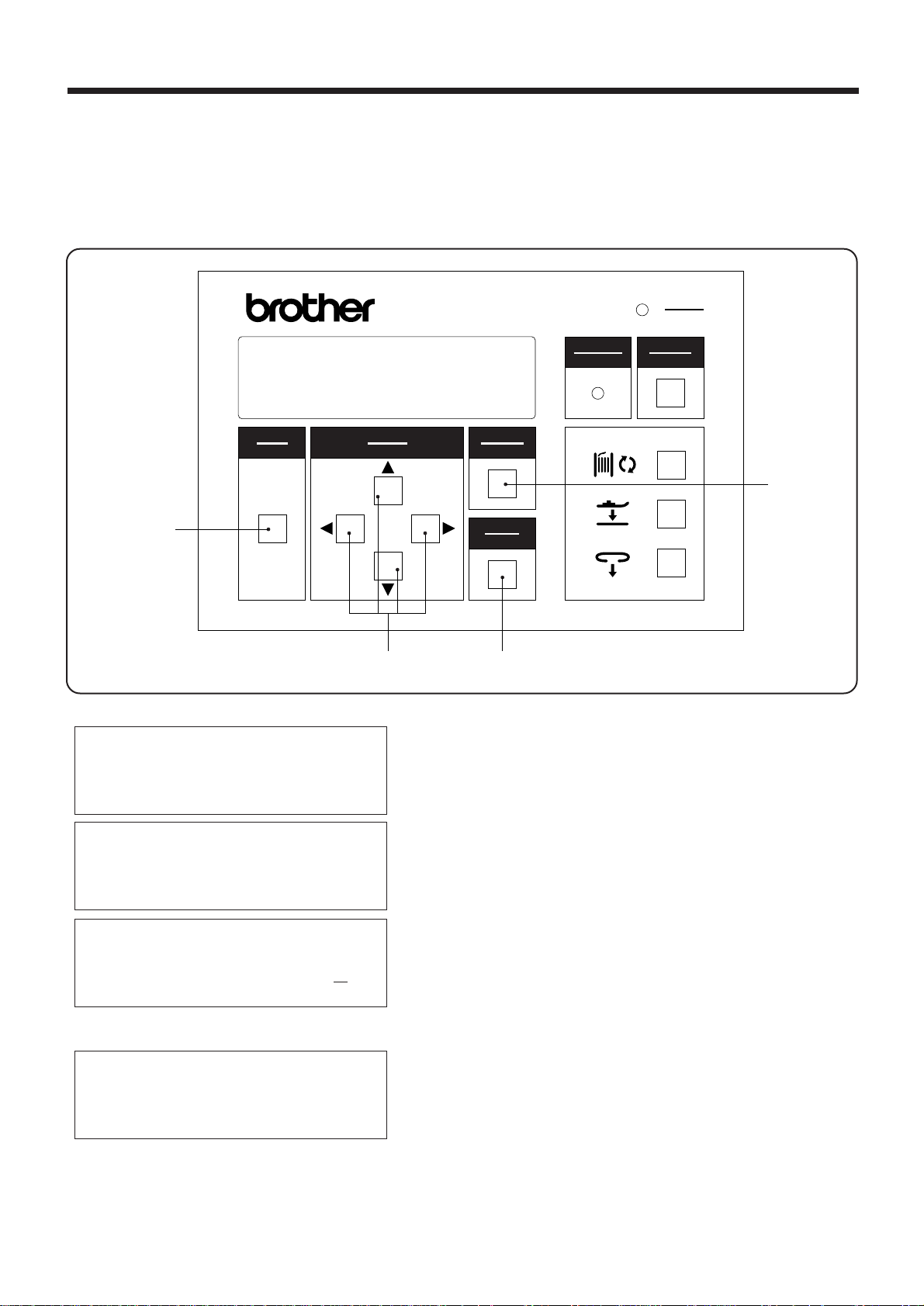
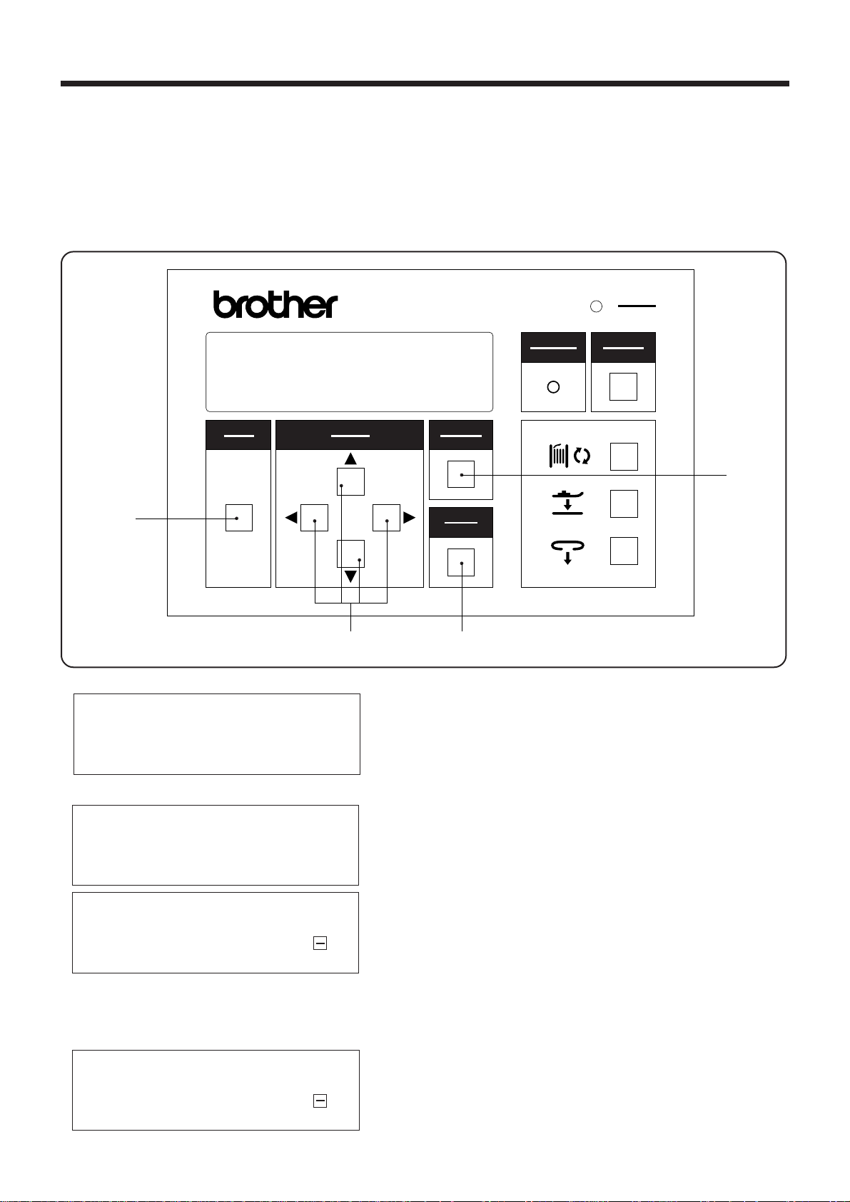
3-1. Explanation of panel
BAS-705
警告
WARNING
display
電源
POWER
リセッ ト
RESET
y
モード
MODE
選択
SELECT
取り消し
CANCEL
u
w
確定
ENTER
i
o
te
q POWER indicator:
w MODE switch:
e SELECT switch:
When the power is turned on, the indicator lights to show that the power is on
This switch is used to switch between AUTO mode, HEAD mode and PROGRAM
mode.
During AUTO mode, the ▲and ▼ SELECT switches are used to switch the
contents of the display.
During PROGRAM mode and ADJUSTMENT mode, the SELECT switches are
used to select items and to input settings.
r CANCEL switch:
This switch is used to cancel the changing of a setting or to cancel the selection
of an item.
t ENTER switch:
This switch is used to accept changes made to any of the settings and selection
of items.
y RESET switch:
This switch is used to reset the machine when an error occurs, and to raise the
presser foot when it has been lowered using the FOOT switch. In addition, it is
used to lock a module which has been unlocked using the BOBBIN switch.
u BOBBIN switch:
i FOOT switch:
o LOOP switch:
!0 WARNING indicator:
This switch is used to open a module when replacing a bobbin.
This switch is used to lower the presser foot when threading the bobbin thread.
This switch is used to set belt loops.
This indicator illuminates when an error has occurred, and when the MODULE
switch or FOOT switch has been pressed.
NOTE:
The machine will not start while the WARNING indicator is illuminated, even when the START switch is pressed.
After turning on the power, press the START switch to determine the home position.
― 12 ―
BA S -705
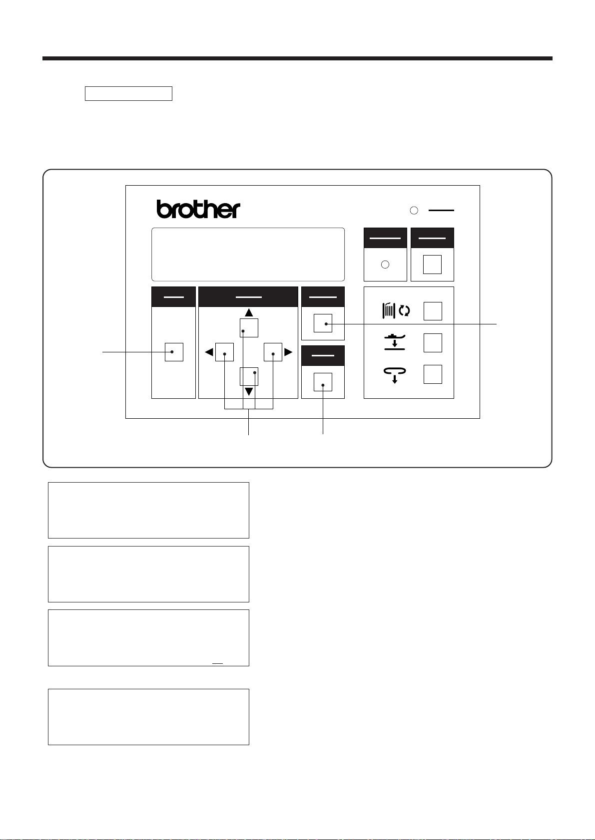
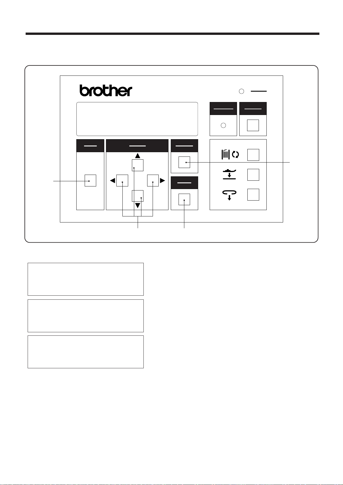
3-2.Data setting methods
PROGRAM mode
3-2-1.Setting the belt loop feeding-out length
・ This sets the length of belt loop material to be fed out before it is cut.
・ The length can be set to between 50 - 120 mm.
3. PANEL OPERATION
w
PROGRAM MODE
◆2nd bobbin counter
Speed
Loop length
モード
MODE
BAS-705
選択
SELECT
e
電源
POWER
警告
WARNING
取り消し
CANCEL
リセッ ト
RESET
r
確定
ENTER
t
1. Press the MODE switch w to select PROGRAM
mode.
PROGRAM MODE
2nd bobbin counter
Speed
◆Loop length
PROGRAM MODE
2nd bobbin counter
Speed
◆Loop length z//
PROGRAM MODE
2nd bobbin counter
Speed
◆Loop length zzb
2. Use the ▲ and ▼SELECT switches e to move the
pointer " ◆ " so that "Loop length" is selected.
▲
3. While using the SELECT switch eto move the
cursor "-", press the▲and▼ SELECT switches e
to set the desired belt loop length.
* If the CANCEL switch r is pressed, the setting
will remain at the previous length setting.
4. Press the ENTER switch t to accept the new length
setting. The cursor "-" will then disappear.
― 13 ―
BA S -705
3. PANEL OPERATION
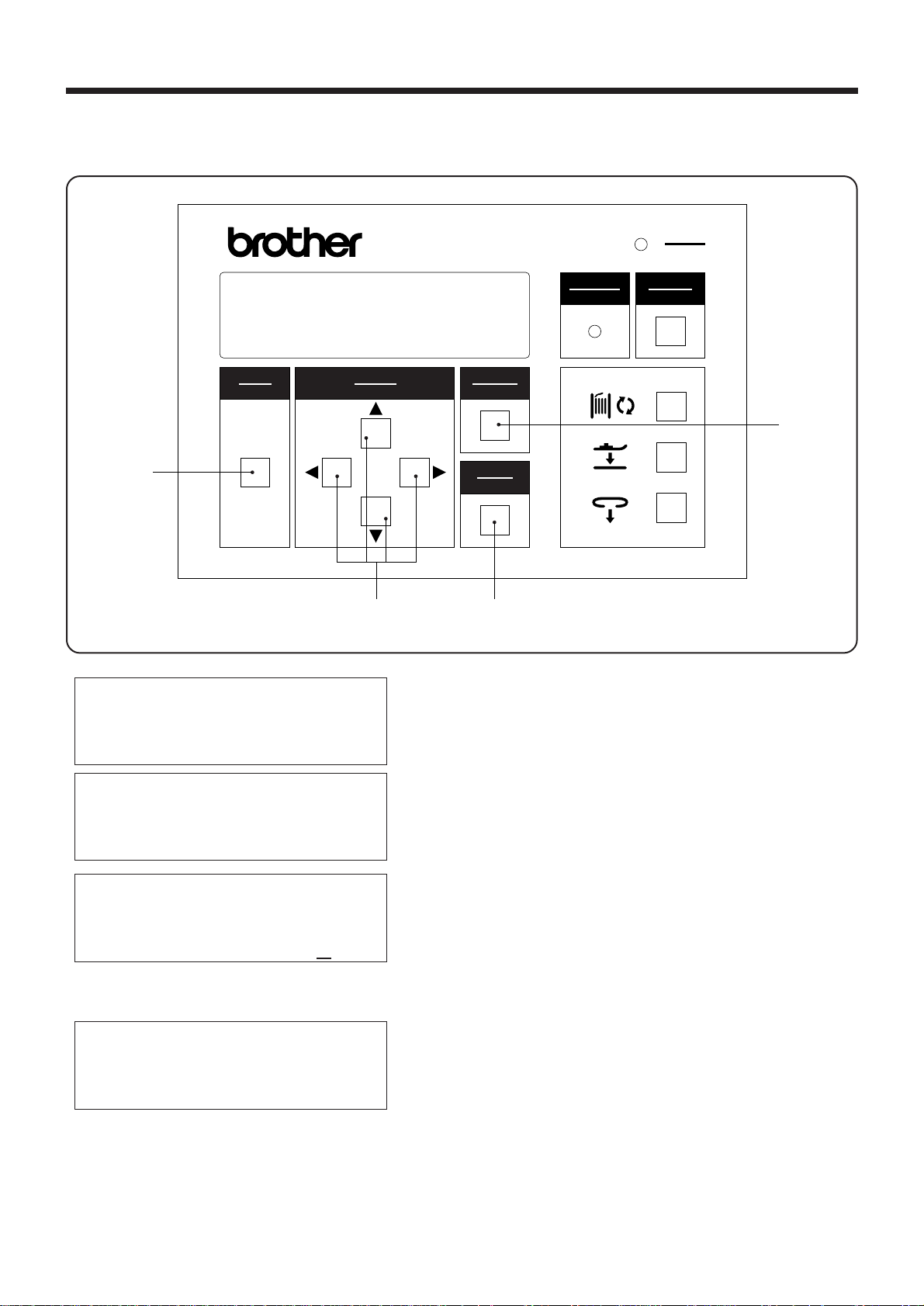
3-2-2. Setting the bobbin counter
・ When the bobbin has been replaced, you need to set the number of bar tacking stitches that the
new bobbin can be used for.
・ The counter setting decreases by 1 each time a single bar tacking is sewn.
・ The bobbin counter operation can also be disabled if required.
・ The setting range is 0 - 999.
モード
MODE
SELECT
w
PROGRAM MODE
◆Production counter
1st bobbin counter
2nd bobbin counter
PROGRAM MODE
Production counter
◆1st bobbin counter
2nd bobbin counter
PROGRAM MODE
Production counter
◆1st bobbin counter ,//
2nd bobbin counter
PROGRAM MODE
Production counter
◆1st bobbin counter ,,,
2nd bobbin counter
BAS-705
選択
電源
POWER
警告
WARNING
取り消し
CANCEL
リセッ ト
RESET
r
確定
ENTER
te
1. Press the MODE switch w to select PROGRAM
mode.
2. Use the ▲ and ▼SELECT switches e to move the
pointer " ◆ " so that "1st bobbin counter" or "2nd
bobbin counter" is selected.
3. While using the SELECT switch e to move the
cursor "-", press the ▲ and▼SELECT switches
e to set the desired bobbin counter setting.
* If the CANCEL switch r is pressed, the old
previously-set bobbin counter setting will appear
again on the display.
4. Press the ENTER switch t
*
The new bobbin counter setting will appear on
the display.
〈To disable operation of the bobbin counter〉
*
Enter "0" as the value when making the bobbin
counter setting.
▲
― 14 ―
BA S -705
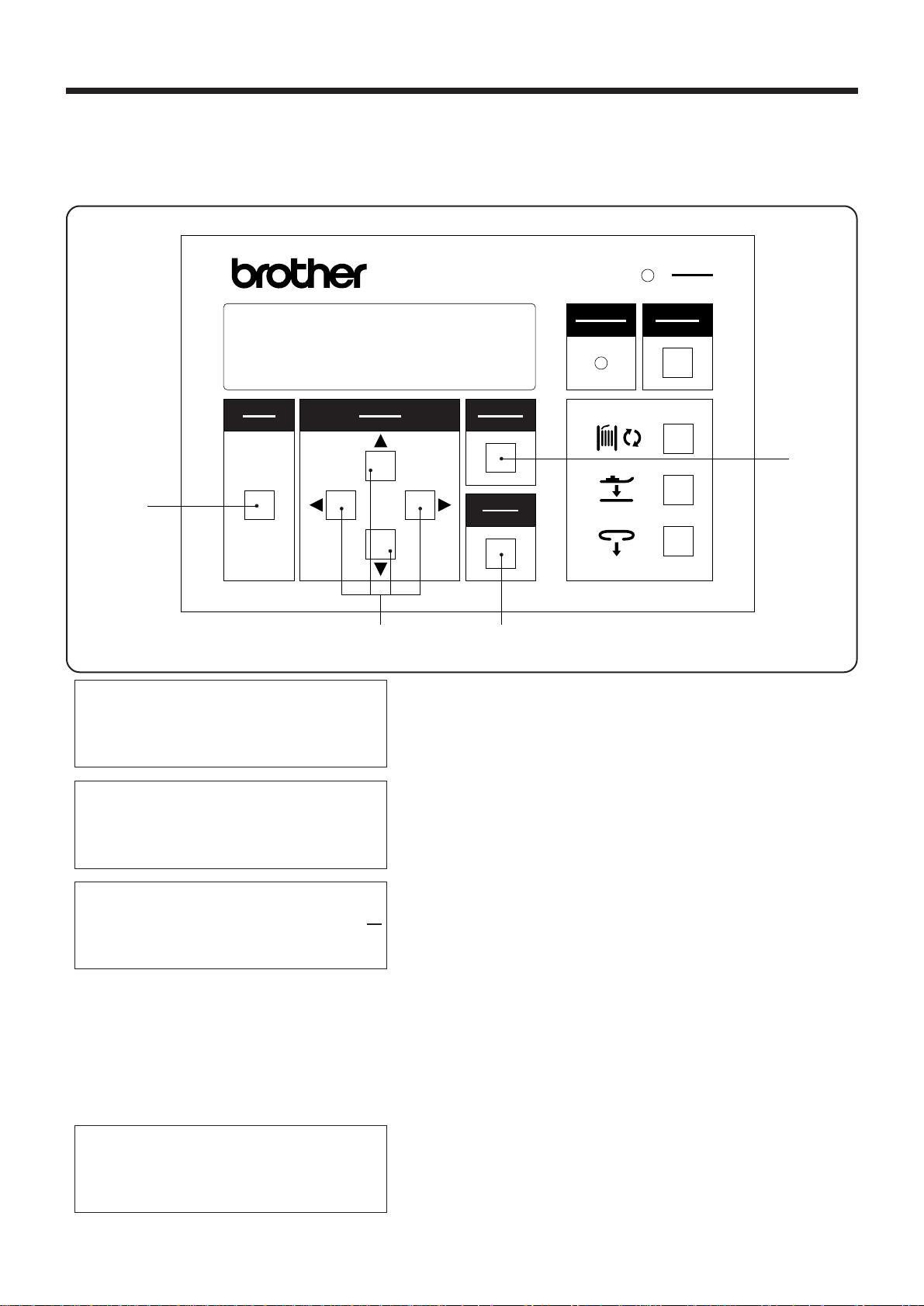
3-2-3 .Clearing production counter
・ The production counter increases by one each time a single belt loop is sewn.
・ The production counter can count up to a maximum of 9999.
3. PANEL OPERATION
w
モード
MODE
BAS-705
選択
SELECT
取り消し
CANCEL
確定
ENTER
te
警告
WARNING
電源
POWER
リセット
RESET
r
PROGRAM MODE
Production counter
1st bobbin counter
◆2nd bobbin counter
PROGRAM MODE
◆Production counter ,,,,
1st bobbin counter
2nd bobbin counter
PROGRAM MODE
◆Production counter /
1st bobbin counter
2nd bobbin counter
1. Press the MODE switch w to select PROGRAM
mode.
2. Use the ▲ and ▼SELECT switches e to move the
pointer
"◆"
so that "PRODUCTION COUNTER" is
selected.
▲
3.
Press the SELECT switch e to change the display to "0".
* If the CANCEL switch r is pressed, the old
production counter setting will appear again on
the display.
4. Press the ENTER switch t.
* The production counter setting will now be
cleared.
― 15 ―
BA S -705
3. PANEL OPERATION
3-2-4.Setting the machine sewing speed
・ Set the machine sewing speed to the maximum sewing speed.
・ The sewing speed can be set to between 1,900 - 2,100 spm in units of 100 spm.
w
モード
MODE
BAS-705
選択
SELECT
取り消し
CANCEL
確定
ENTER
te
警告
WARNING
電源
POWER
リセット
RESET
r
PROGRAM MODE
◆1nd bobbin counter
2nd bobbin counter
Speed
PROGRAM MODE
1nd bobbin counter
2nd bobbin counter
◆Speed
PROGRAM MODE
1nd bobbin counter
2nd bobbin counter
◆Speed z.//
PROGRAM MODE
1nd bobbin counter
2nd bobbin counter
◆Speed x///
1. Press the MODE switch w select PROGRAM mode.
2. Use the ▲ and ▼SELECT switches e to move the
pointer "◆" so that "SEWING SPEED" is selected.
▲
3. While using the SELECT switch e to move the
cursor "-", press the ▲ and▼SELECT switches e
to set the desired machine sewing speed.
* If the CANCEL switch r is pressed, the old sewing
speed counter setting will appear again on the
display.
4. Press the ENTER switch t
* The new sewing speed setting will appear on the
display.
― 16 ―
BA S -705

ADJUSTMENT mode
・
Adjustment of the belt loop feeder and of the X-Y feed for the machine head are carried out in this mode.
・ If the MODE switch w is pressed in ADJUSTMENT mode, the mode will switch to SEWING mode.
3-2-5. Loop feeding
・ Continuous operations are carried out one step at a time.
・ This is useful to use for checking adjustment and operation.
3. PANEL OPERATION
BAS-705
警告
WARNING
電源
POWER
リセット
RESET
y
モード
MODE
選択
SELECT
取り消し
CANCEL
r
w
e
AUTO MODE
◆2nd bobbin counter
Speed
Loop length
ADJUSTMENT(/)
◆Loop/feed
X-Y/program
X-Y/test feed
LOOP/FEED/(ADJ)
▲SW Forward step
▼SW Backward step
NOTE:・During step operation, one of the steps is taken up with determining the home position for the upper
shaft and lower shaft.
・Note that actual sewing is also included in step operation. (Warning beeps will sound when sewing
starts.)
<To return to ADJUSTMENT mode during step operation>
* Press the CANCEL switch r.
<If the upper thread breakage codes (E-181, E-182) are displayed during step operation>
・ Thread the upper thread properly.
・ Press the CANCEL switch r. The mode will then switch to ADJUSTMENT mode.
確定
ENTER
t
1. Press the MODE switch w to select AUTO mode.
2. While pressing the SELECT switch e, press the
MODE switch w.
* This will change the mode to ADJUSTMENT
mode.
3. Use the ▲ and▼SELECT switches e to move the
pointer "◆" so that "Loop/feed" is selected, and then
press the ENTER switch t.
4. Press the▲ or ▼SELECT switch e.
* If the▲ SELECT switch e is pressed, the
machine will operate step by step in the forward
direction.
* If the▼SELECT switch e is pressed, the
machine will operate step by step in the backward
direction.
* Press the CANCEL switch r to resume normal
operation.
▲
― 17 ―
BA S -705
3. PANEL OPERATION
3-2-6. Setting the program number
・ This procedure is used to set the program number for a sewing pattern.
・ The standard sewing patterns are 1 (29 stitches), 2 (36 stitches) and 3 (43 stitches).
w
AUTO MODE
Production counter
◆1st bobbin counter
2nd bobbin counter
ADJUSTMENT(/)
Loop/feed
◆X-Y/program
X-Y/test feed
モード
MODE
BAS-705
選択
SELECT
電源
POWER
警告
WARNING
取り消し
CANCEL
確定
ENTER
リセット
RESET
r
te
1. Press the MODE switch w to select AUTO mode.
2. While pressing the SELECT switche e , press
the MODE switch w.
*
This will change the mode to ADJUSTMENT mode.
3. Use the ▲ and ▼ SELECT switches e to move the
pointer "◆" so that "X-Y/program" is selected,
and then press the ENTER switch t.
▲
X-Y/PROGRAM/(ADJ)
◆Program No. x
X scale (%)
Y scale (%)
X-Y/PROGRAM/(ADJ)
◆Program No. z
X scale (%)
Y scale (%)
4. Use the ▲ and ▼ SELECT switches e again to
move the pointer "◆ " so that "Program No." is
selected.
▲
5. While using the SELECT switch e to move the
cursor "-" , press the ▲ and▼SELECT switches e
to set the desired program number.
* If the CANCEL switch e is pressed, the old previ
ously-set program number will appear again on
the display.
6. Press the ENTER switch t.
* The new program number setting will appear on
the display.
* At this time, the feed mechanism, will move to
the sewing start position.
― 18 ―
BA S -705

3. PANEL OPERATION
3-2-6-1. Pattern selection mode
* The following procedure lets you select the stitch pattern.
There are three different basic patterns which can be selected, and these patterns are pre-programmed
into the sewing machine's ROM.
X-Y/PROGRAM/(ADJ)
Program No. MM
Xscale(%)
Yscale(%)
* The enlargement and reduction settings can be applied to each of the patterns as described below.
Program No.11/21/31‥‥‥‥Set based on program No. 1
Program No.12/22/32‥‥‥‥Set based on program No. 2
Program No.13/23/33‥‥‥‥Set based on program No. 3
NOTE:
If the ENTER switch is pressed while any patterns other than the above are selected,setting
will not be possible.
[Operation method]
* Use the ▲ and ▼ SELECT switches e to change
the numbers, and use the and SELECT switches
▲
▲
e to move the cursor "-" .
選択
SELECT
e
取り消し
CANCEL
確定
ENTER
t
r
[Input method]
* The patterns that can be set are the patterns with
numbers from 1 to 3.
1. Press the ENTER switch t to select the second
line of the display.
2. Use the ▲ and ▼SELECT switches e to change
the numbers, and use the and SELECT
▲
▲
switches e to move the cursor "-" .
3. If the CANCEL switch r is pressed while the
cursor "-" is displayed, the display will return to
the item selection display without the setting being
changed.
4. If the ENTER switch t is pressed while the cursor
is displayed, the setting value will be changed to
the value displayed and the display will return to
the item selection display.
― 19 ―
BA S -705

3. PANEL OPERATION
3-2-7. Setting the X scale and Y scale
・ This procedure is used to set the enlargement and reduction ratios for the sewing pattern in
the X direction and Y direction.
・ The setting ranges for both the X scale and Y scale are between 45% - 150%. However ,because
the size of the pattern will be checked against the sewing area, it may not be possible to set
the scale to the maximum setting in this range.
モード
MODE
選択
SELECT
w
AUTO MODE
◆2nd bobbin counter
Speed
Loop length
ADJUSTMENT(/)
Loop/feed
◆X-Y/program
X-Y/test feed
X-Y/PROGRAM/(ADJ)
Program No.
◆X scale (%)
Y scale (%)
X-Y/PROGRAM/(ADJ)
Program No.
◆X scale (%) z//
Y scale (%)
X-Y/PROGRAM/(ADJ)
Program No.
◆X scale (%) zz/
Y scale (%)
BAS-705
電源
POWER
警告
WARNING
取り消し
CANCEL
確定
ENTER
リセット
RESET
r
te
1. Press the MODE switch w to select AUTO mode.
2. While pressing the SELECT switch e, press the
MODE switch w.
* This will change the mode to ADJUSTMENT
mode.
3. Use the▲and ▼SELECT switches e to move the
pointer "◆" so that "X-Y/program" is selected, and
then press the ENTER switch t.
4. Use the ▲ and ▼ SELECT switches e again to
move the pointer "◆" so that "X scale" or "Y scale"
is selected.
5. While using the SELECT switch eto move the
cursor "-" , press the ▲ and▼SELECT switches e
to set the scale setting.
* If the CANCEL switch r is pressed, the
old previously-set scale ratio will appear again
on the display.
6. Press the ENTER switch t.
* The new scale ratio setting for the X scale or Y
scale will appear on the display.
* At this time, the feed mechanism will return to
the sewing home position.
▲
▲
― 20 ―
BA S -705

3-2-8. X and Y step feed
te
・ The sewing pattern can be checked by carrying out step operation.
3. PANEL OPERATION
モード
w
AUTO MODE
◆2nd bobbin counter
Speed
Loop length
ADJUSTMENT(/)
Loop/feed
X-Y/program
◆X-Y/test feed
X-Y/TEST FEED(ADJ)
◆Step feed
Real feed
STEP FEED/(ADJ)
▲ SW Forward step
▼SW Backward step
▲
( SW fast)
MODE
BAS-705
選択
SELECT
電源
POWER
警告
WARNING
取り消し
CANCEL
確定
ENTER
リセット
RESET
1. Press the MODE switch w to select AUTO mode.
2. While pressing the SELECT switch
MODE switch
w.
▲
e, press the
* This will change the mode to ADJUSTMENT
mode.
3. Use the ▲and ▼SELECT switches
e to move the
pointer "◆" so that "X-Y/test feed" is selected, and
then press the ENTER switch t.
4. Use the ▲and ▼SELECT switches
e again to
move the pointer "◆ " so that "X-Y step feed" is se
lected, and then press the ENTER switch t.
5. Press the ▲ or ▼SELECT switch
* If the ▲ SELECT switch
e is pressed, the machine
e.
will operate step by step in the forward direction.
* If the SELECT switch
e is pressed while the
machine is sewing in the forward direction, the
opera tion will switch to backward step oper-
▲
ation.
* If the ▲SELECT switch e is pressed while the
SELECT switch
tion will switch to high-speed forward step op-
e is being pressed, the opera-
▲
eration.
* If the SELECT switch
▲
SELECT switch
▲
e is pressed while the
e is being pressed, the op-
eration will switch to high-speed backward step
operation.
― 21 ―
BA S -705

3. PANEL OPERATION
3-2-9. X-Y feed at real speed
・The sewing pattern can be checked by operating the machine at the real sewing speed.
電源
POWER
w
AUTO MODE
◆2nd bobbin counter
Speed
Loop length
モード
MODE
選択
SELECT
e
警告
WARNING
取り消し
CANCEL
確定
ENTER
リセット
RESET
t
1. Press the MODE switch w to select AUTO mode.
ADJUSTMENT(/)
Loop/feed
X-Y/program
◆X-Y/test feed
X-Y/TEST FEED(ADJ)
Step feed
◆Real feed
REAL FEED (/ADJ/XYFD)
▲SW =execute
2. While pressing the SELECT switch e, press the
▲
MODE switch w.
* This will change the mode to ADJUSTMENT mode.
3. Use the ▲ and ▼SELECT switches e to move the
pointer "◆" so that "X-Y/feed" is selected, and then
press the ENTER switch t.
4. Use the ▲ and ▼SELECT switches e again to
move the pointer "◆ " so that "X-Y real feed" is se
lected,and then press the ENTER switch t.
5. Press the ▲ SELECT switch e.
* Step operation will then be carried out at the real
sewing speed.
― 22 ―
BA S -705
3-2-10. X-Y movement
・ This procedure lets you set the parallel movement of the pattern in the X feed direction
and Y feed direction.
・ The setting range is from -1 to +1 in both the X direction and Y direction. However, it may
not be possible to change the setting within this range because an area check will be
carried out when the setting is changed.
3. PANEL OPERATION
モード
MODE
選択
SELECT
w
AUTO MODE
◆Loop length
1st bobbin counter
2nd bobbin counter
ADJUSTMENT(/)
Loop/ program
◆X-Y/ test feed
X-Y/ feed
X-Y/MOVE/ (ADJ)
Program No.
◆Xmove (mmx10) z/
X-Y/MOVE/ (ADJ)
Program No.
◆Xmove (mmx10) z/
BAS-705
電源
POWER
警告
WARNING
取り消し
CANCEL
確定
ENTER
リセッ ト
RESET
r
te
1. Press the MODE switch w to select AUTO mode.
2. While pressing the SELECT switch e, press the
MODE switch w.
* This will change the mode to ADJUSTMENT
mode.
3. Use the▲and ▼SELECT switches e to move the
pointer "◆" so that "X-Y/program" is selected, and
then press the ENTER switch t.
4. Use the ▲ and ▼ SELECT switches e again to
move the pointer "◆" so that "X move" or "Y move"
is selected.
5. While using the SELECT switch e to move the
cursor "-" , press the ▲and ▼ SELECT switches
e to set the amount of movement.
* If the CANCEL switch r is pressed, the
old previously-set scale ratio will appear again
on the display.
6. Press the ENTER switch t.
* The new scale ratio setting for the X move or Y
move will appear on the display.
▲
▲
― 23 ―
BA S -705
4. SEWING
4. SEWING
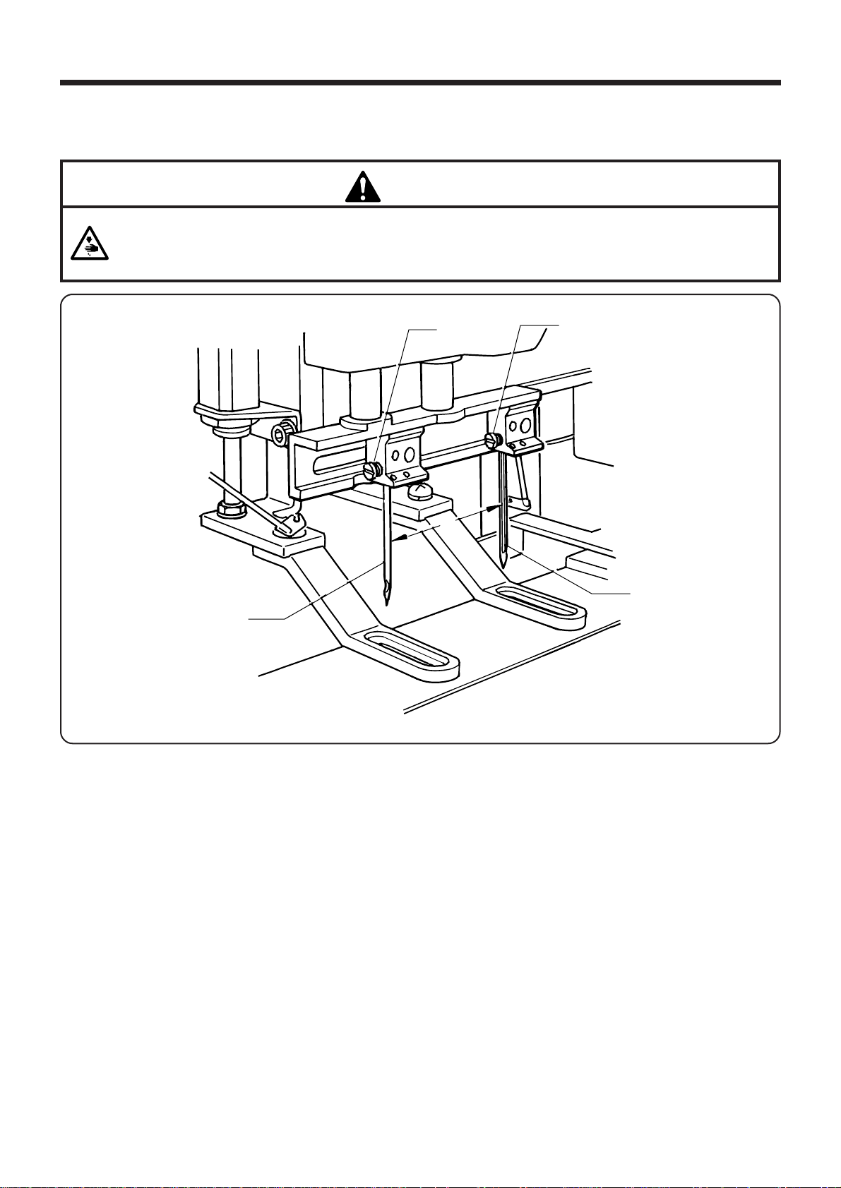
4-1. Replacing needle
・ Turn off the power switch before installing the needle, otherwise the machine may operate of the
start switch is depressed by mistake and serious injury could result.
CAUTION
e
r
A
w
q
1. To install the needle q for the first bar tacking, loosen the set screw w, insert the needle q as far as it will go
so that the long groove is facing toward you (side A), and then tighten the set screw w.
2. To install the needle e for the second bar tacking, loosen the set screw r, insert the needle e as far as it will
go so that the groove is facing away from you (side A), and then tighten the set screw r.
― 24 ―
BA S -705
 Loading...