

Page 1
INSTRUCTION
MANUAL
T-8421A,
T-8722A
T-8452A,
2
^(Oiawij:.
TWIN
Please
Please
DOS
Por
Por
NEEDLE
read
this
keep
this manual within
AGUJAS
favor
lea
favor
guarde
este
manual
manual
este
before using
antesdeusarlamaquina.
manual al
8422A
8752A
DIRECT
the
machine.
easy
reach
CON
MOTOR
alcancedela
DRIVE
for quick
mano
MANUAL
U'eLX<tm\
LOCK
reference.
INCORPORADO
para
una
rapida
referenda.
DE
INSTRUCCIONES
STITCHER
brother.
Page 2
T-8421A
T-8422A
T-8452A
T-8722A
T-8752A
2
:$:^2f;il^>ru^hK7'r:?^^:*:llgi!i^^oy5S/>
Page 3
•^=7-*f-ms,i:^mmi^tztc^-^l-c.
^ztiz^<')t>itor^l^s•ro
TL^^fcl^tllorL^^f
LTgi^^®«lalc!^g|J«)c:KJ[Sl^f=fc*t^•r
o
t
z
^^®jElC^!l31L•C<tzH,\
r<fc*$i\
«•
t
LrfiiaL-c<f=$tv
j:5fcgiL^i^fc
L^-r,
5
Z«iaL
tt«g®a&a.
^()!)i&a<o«®$(S)$-r«t:«>i=!e»ii«j:®a7-r.
Page 4
z0t=ifify'7->f-i.mms.lt.
[$±l=j3ffiUl\fcfc*<fc«>l=]fc<):0:®at^«)KPSJ:<
s^ti=&yA<t
5
j3BS»<fc*SU.
xaffls-»ii-t<!5tt»j:,
f
ss:»A<fcy
1.
$#(COt^'C(D^7iv^"?"(D^I^
7T\
«-r.
t
mM\tllk(D
c®a^^fttaLris-3fc»«i.^s-rsi:,
tt•^^5tf^^Eif(Dl6<asa©tt«I•ef^ss1TS:5fc«),
/ci6(7)
tio'O
X'-to
y
s^<t«©fc«)<»a»tg<^®«aiisait<
t>
5Et:sfctt*ts&a5rtg$sL,ri*s-r.
fctoic
si=c*i&fl5as»-e(+A<$
jel
< fc*s
SIH"^
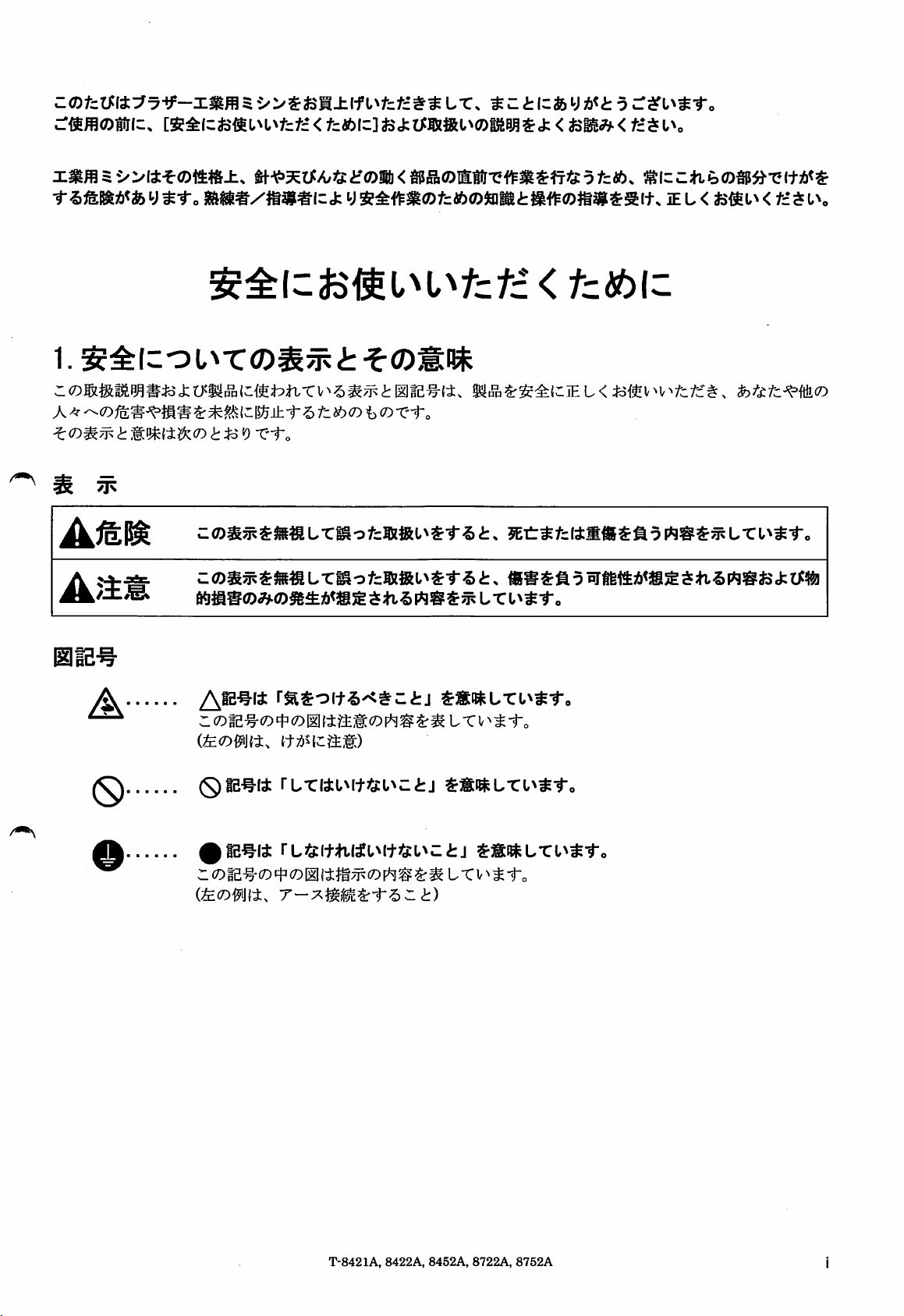
A
(S)
o
rasoitS'C^ctj
r L T V^;^ 1-0
ss:i»Lru«t-,
T-8421A,
8422A,
8452A
8722A,
8752A
Page 5
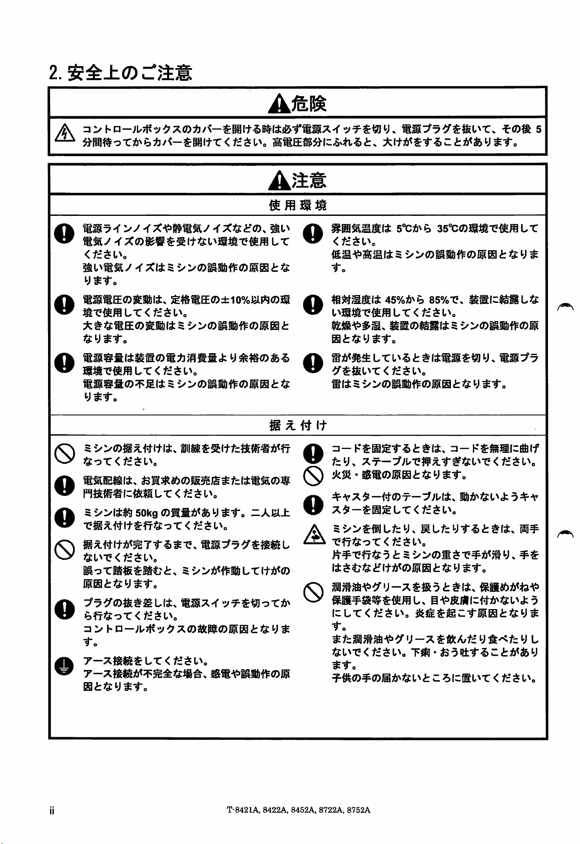
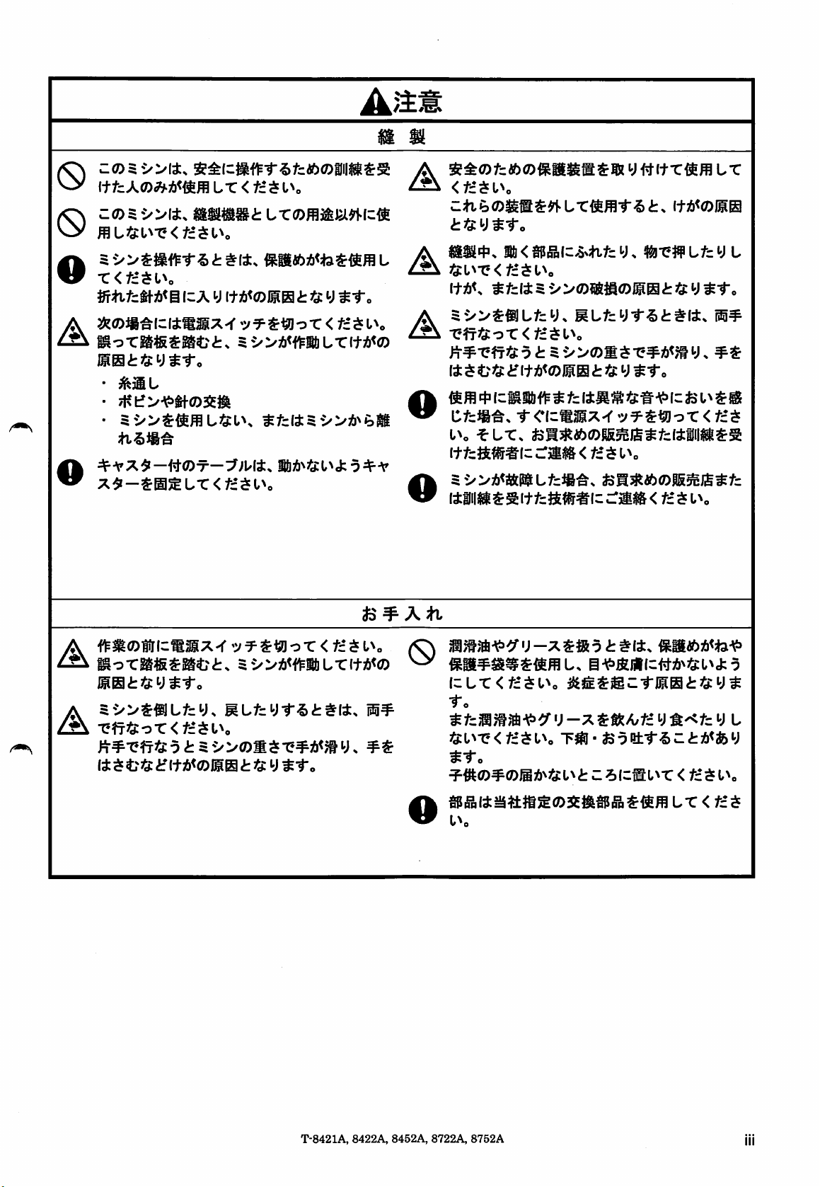
2.
^±±<0
cram
A
®s^-f
mst/
<fc*^tv
iSl^aay
ys-r.
e®SE®giiii4,
X#«:SE®g|||l4
ft
y o
mi9®fii4Ss®aA;HS5<j:
o
Sii$a®7ei4s
y^-r.
-fx-^waay
-f
XI45'>
-cxiEcif®.
:/®^ili#®
;s4$SE®±io%iem®s
S
•»®MU1^®®B
•>>®^n'f^®igB£;«
SBtis
ysi;^®®'^
SSE®»lw54i.«i:.
llfflmSSli
^
^ #
o
•fo
o
i^mmv^mLx<tz^i\
mttj:i)^to
mit^
(t
UT
*l+A<Sf.5-tA<feyS-To
5"CAnP)
45%A^^
i/>0)^16^(01101
35"C0^it-e^$fflL-C
85%-^.
gglcfgggL^f
tny^-r
o
0
tJi'oX<tz^l\
pm^l^#Icflc^Lr<tc^L^o
5-»i4iS!!i50kg®afiA<fcys-r«
•C«x#it
0
'Sl^1?<*:Sl,V
MoTa«Sat?i:.
BBt'sys-r.
X7^^®fttllUli.
a >
•f.
o
T-XSE«^)b<:i^gaft«a,
atfty^-r.
sm<E
1-•-;i/7|?-v
O r < t= s
5-»A<<^ilUr(+3!i<®
m3SX-(••y^S«lor!6^
<7X®»Pt®)SB
1\
lSa-¥>S«f^®IS
-Am±
i:fty *
o
f=y.
0
^A'X^-#(Z)ir-::f;Ki,
X-r—:^;u-eff^-r^35:t^"e<t£$L^o
•
®a0ll01
o
5»^iijLfcy.
A
•etr^Cor
)i¥'CfT^C9
14$ 4?j4iflt36<01101
ii7t}S^^y-X$iR9i:^I4.
0
\zLX<tztSl\
to
tjil'^x<tztsi\
^•To
^•#t(D¥<0ig:^l^3^i:l^ t Z
jS:
y
<f£$L^o
i:
5>>(OS$'C^^<7ty
iS13£^®C-ril0i:J5:y^
T^-
i6;6>^i:i^J:9+A'
fs:y
^to
fcottf
5(c®l\T
^::i:/»<fey
<
^
tztSl\
T-8421A,
8422A,
8452A,
8722A,
8752A
Page 6
O
(S)
o
i-ftzxoMmm
mLi3il\X<tz^l\
X<tz^l\
Lx<tz^i\
izxy(t}b<©l^Si:'S:y^-To
A
A
<tz^l\
<t?Ei:y^-ro
35:L^-^<y'=$l^o
Ws
i!i<spp°B(wSNtttcy.
^fc(i5i/>a)?®tia)iistJ5:y^-ro
w^oiis
Lfcy
l
^0ii^ici4mMx>r
A
iis^«:y^-r«
•
^jIL
•
O
X^-^m^LX
Af^HOfricmMX-r
issi:3jpy^-ro
^?^T^i:or<f£$l^0
li
ts t tj: y
5e/>3&<f^aLr(tA<a)
<tztsl\
':/T^^oT<t£$l^o
<
tztsi^
^fc(±5i/>A^e)gi
^to
is
^ ^ ^
^
xntii'DXKtz^l^o
y
^to
ctzm-^st
i\
^LXs
itf=ftts#(c
(illi|ili^sitf=stfi5#lc:rii«&<
\zLX<tztSl\
to
i^fzmmfA'<=><f')-x^$kAjtz^)'k^fz^)
^^:l^T'<f£$l^o
tto
=F^(D^(Dmi)''tj:i\tZ^lzmi^X
dzmmx^
fcl3Ktoa)S5^j£^fcttiii«i^s
::mm<tz$L^o
T^-fcaet-r-5Zi:A<fey
^ o r < f£ $
f£$L^o
<
L
tzt^l\
l\
T-8421A,
8422A,
8452A,
8722A,
8752A
Lx<tzts
Page 7
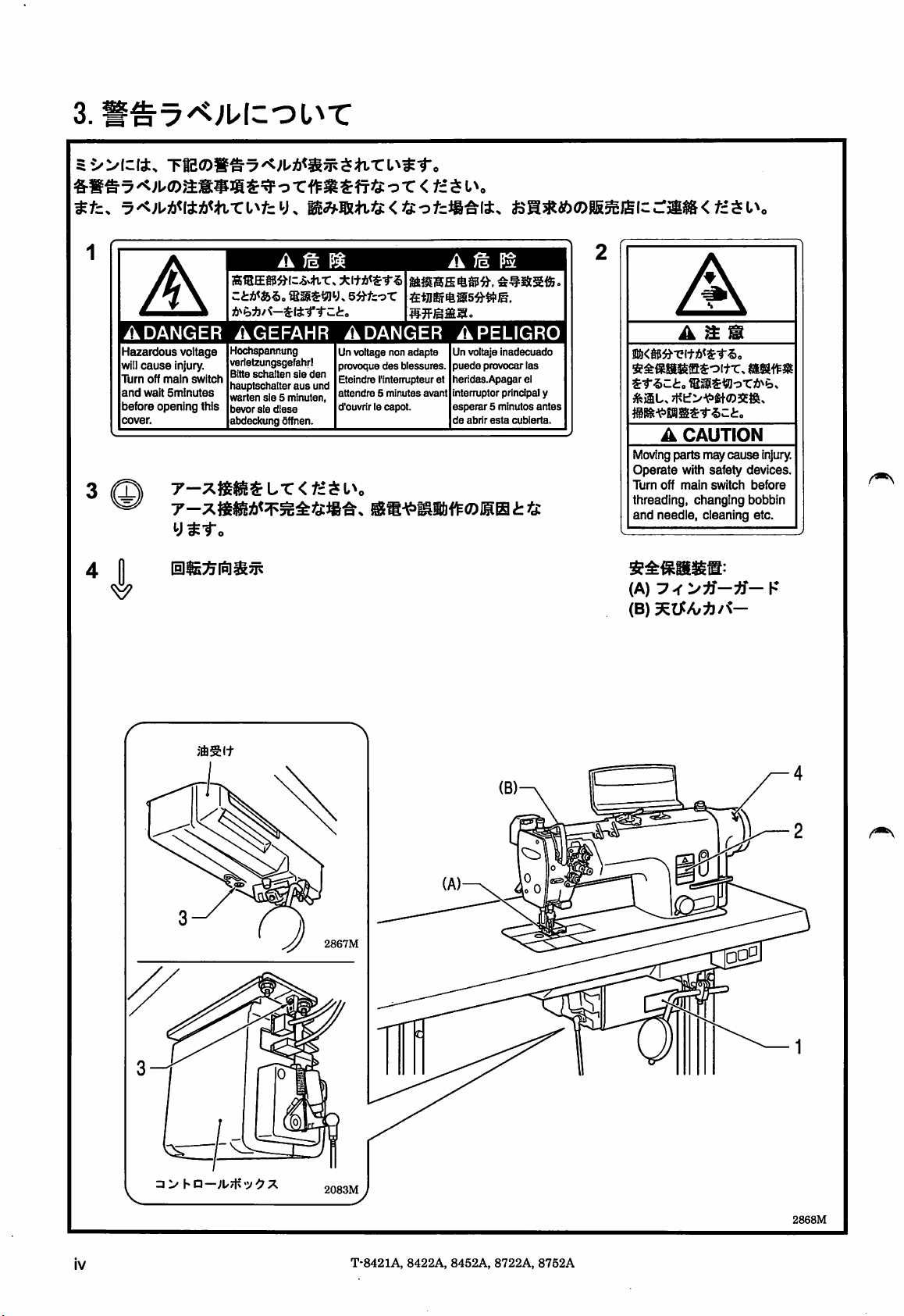
3.
^tz.
1
A
A\
ADANGER
Hazardous
will
Turn
and
before opening this
cover.
voltage
cause
Injury.
off
main
wait
switch
Sminutes
T-XfilSI$Lr<f£^Uo
y^-To
m^^Hi3:<i3:'Dtzm'^\t.
A
/g
B®ES5»l=-5-*iT»
ztii<&^o
®as^«jy.
AGEFAHR
Hochspannung
verielzungsgefahrl
Bitte
sch^ten sie den
hauptschalter
warten
bevor
abdeckung fiffnen.
aus
sie5minuten,
sie
diese
Pt
5ij-fcoT
ADANGER
Un
voltage
provoque
Eteindre I'internjpteur et
und
attendre5minutes
d'cuvrir le
ncn
des
capot.
adapte
biessures.
avant
fcl^«)0l55SJ£lc
A ^ P^
APELIGRO
Un voltaje
puede
lieridas-Apagar el
interrupter principal y
esperar
de
provocar las
5 minutes
abrir
esta
inadecuado
cubierta.
antes
c:^$&<fi$l^.
A
mm
m<m-Q\imt^o
s^ftssfflsoi+TT.
ife>iL,7t?lf>A;>W0SESi,
sss^Worjb^b.
A
CAUTION
Movingparts may
Operate
Turn
with safety devices.
off
main
switch
cause
«isaf^i8
injury.
before
threading, changing bobbin
and
needle, cleaning etc.
(A)
(B)
• >
hn—
®SI+
2867M
2083M
IV
T-8421A,
8422A,
8452A, 8722A,
8752A
2868M
Page 8
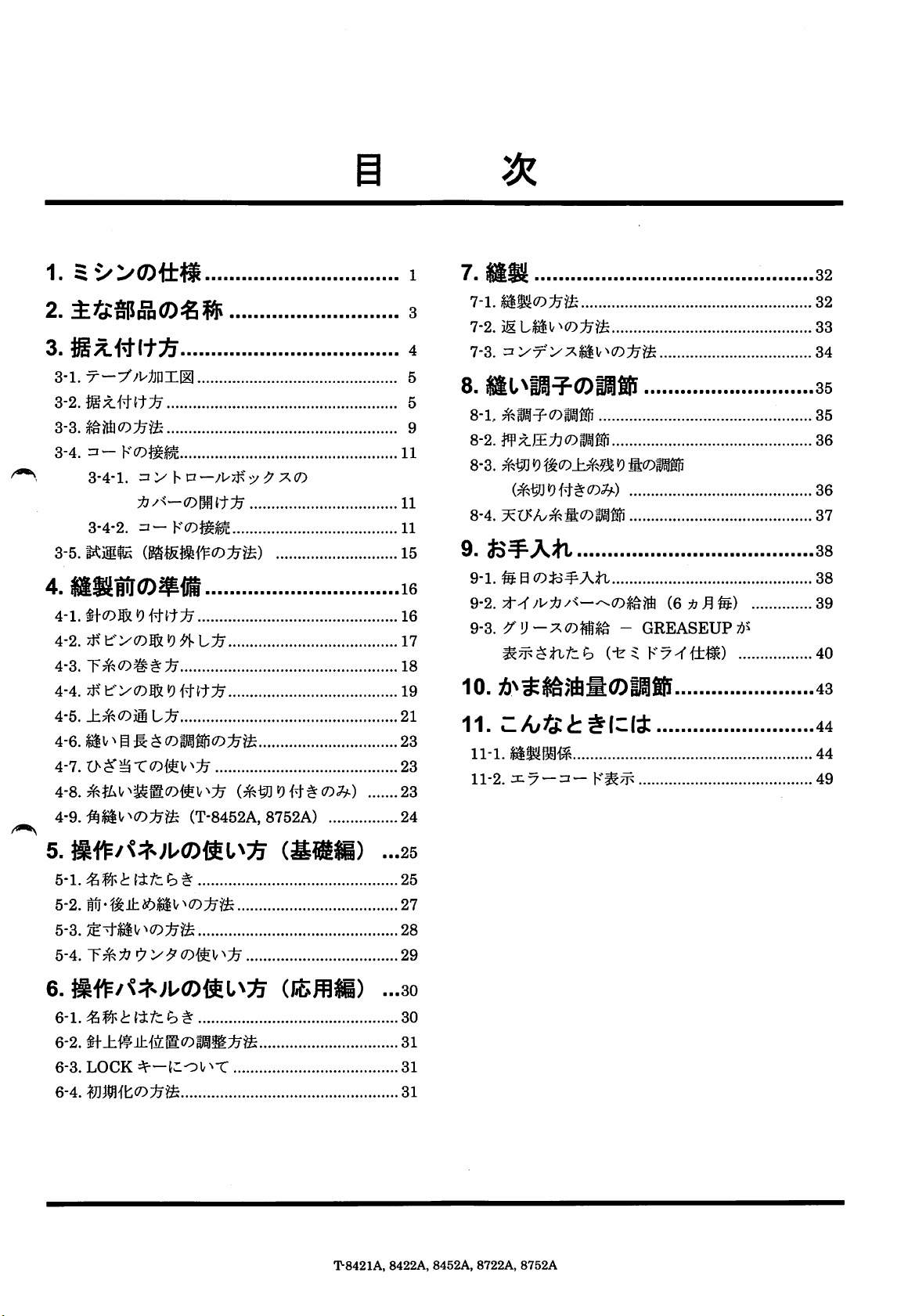
1.
1
7a
mm
32
2.
p|5pp(D€l$
3 a aaaaaaaaaaaaaaaaaaaaaaaaaaaaaaaaaaaa 4
3-1.
X—-//l^APXIgl
3-2.^;t#{t;^
3-4.
n-
Y(D^^
3-4-1.=1>'hP—/PtK
t)
3-4-2.
3-5.KillE
5/^XCO
4.«lilfr®*fii
4-1.
4-2.
4-3.
4-4.
4-5.
^
Ai^<Dm\^1j
4-6. HV ^g fi: ^
4-7.
4-8.
4-9. (T-8452A, 8752A) 24
19^LIj
19#it
(D^^(D:^^
(^^19
##(79^)
11
11
11
15
16
16
17
18
19
21
23
23
23
3
5
5
9
7-1.
7-2.
7-3.
8.
8-1,
8-2.W^J£t}(Dfm
8-3.
m]^'ik(o}jhmm(Dwm
(^^Jf9##C0^)
8-4.
9a a
9-1.
fe0(7)iQ^Att
^•2.-^^{6:fjM^)
9-3.
a.aaaaa
-
GREASEUP;7,s
(ir^Ky^tt^)
10.
11.
ll-l.i^«M«
11-2.
X y —=1— \^'^7jk
32
33
34
35
35
36
36
37
38
38
39
40
43
44
44
49
5a
5-1.
5-2.
5-3.
5-4.
6.
6-l.^W^tittch
6-2.
^±W±i\LW:(DmM:fyW:
6-3.
LOCK
Q-AAJ]M\t(Dlom
dr-^^oV^-C
^
i^^m)
(JBfflli)
T-8421A,
...25
25
27
28
29
...30
30
31
31
31
8422A,
8452A,
8722A,
8752A
Page 9
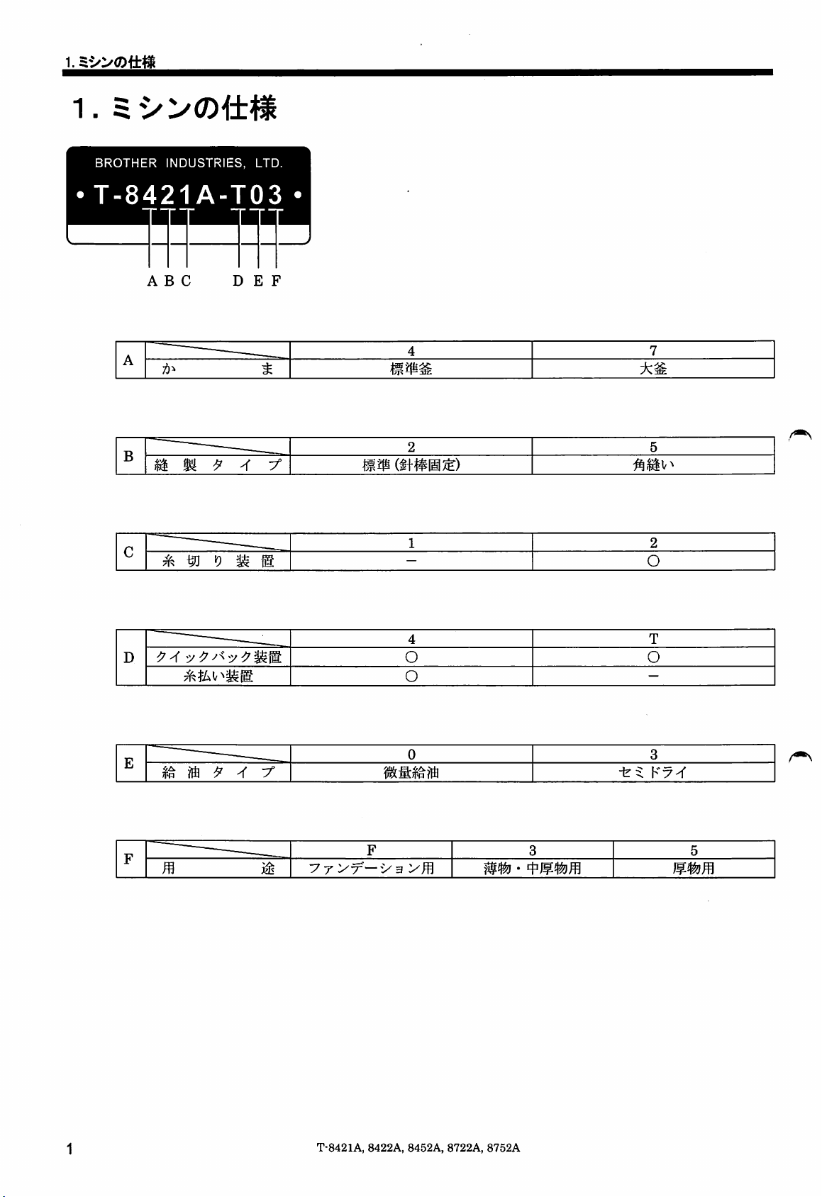
1.
1.
BROTHER
INDUSTRIES,
T-8421A-T03
ABC
A
/j'
B
m m
C
^ ^
—
19
LTD.
D E F
t
^ ®
mm
4
2 5
1 2
—
7
O
4 T
^ y{
D
E
1?
r
® ^
"
J1
-r
yf—y-B
ji^
y T
o o
o
0 3
F
3 5
yWi
—
T-8421A,
8422A, 8452A,
8722A,
8752A
Page 10
T-8421A
——
§ v^
^ ± ^
V^
ii
ii it
M -X m ^ ^ ^
^ X ^ ^ ^
Jf
t>
±
(f
T r
±
ffl ( D P X 5 )
ftiij
T-8422A
^ a
m m m
Jh J6 ^
V^
ii
ji
^ X m ^ ^
X.
ill
(7)t^$
^9
n
XX\-fX
t>
H
CO
±
1^ ^
^ ^ ( D P X 5 )
0 SS
1.
-T3F
it
3,000rpm
-T33
3,000rpm
-T03
4,000rpm
-T05
3,000rpm
250~l,800rpm
l,000rpm
4mm
7mm
(f
$
#9~#14
13mm
1mm
#11'-#16
5mm
#14~#22
(4li550W)
-y'^
-403
®
4,000rpm
-433
—^
-405
3,000rpm
250~l,800rpm
g
4mm
:l
(f
#11~#16
AC
f—(4
l,000rpm
7mm
13mm
1mm
^ U ::n
yi:°
m
^ —
5mm
#14~#22
550W)
T-8452A
.
^
^ ± i6 ^
;9c
^
X.
<79
^
l'"^
^f
ii
V^
ii
@ ^
X. ±
ff
-c
x> X
iH
19
it
(79
( D P X 5 )
$IJ
T-8722A,
T-8752A
:& H
tu±a6
•
i§^Jlii6^V^i§it
^ ± a6 ^
^
^ X ^ (D m ^
i^
*9
#
V""
V'*
^ X
r>
<79
0 gg
i^
ii it
@
ft
Xif
X Z
±
rWi
m m n ( D P X 5 )
m m m ^
-403
^
3,000rpm
-405
250^1,800rpm
^
r
if
$
#11~#16
AC (4 m
-403
l,000rpm
5mm
7mm
13mm
1mm
#14~#22
550W)
-405
3,000rpm
250~l,800rpm
l.OOOrpm
^
(f
^
#11~#16
AC
7mm
7mm
13mm
1mm
(4 lig
#14~#22
550W)
T-8421A,
8422A,
8452A,
8722A,
8752A
Page 11
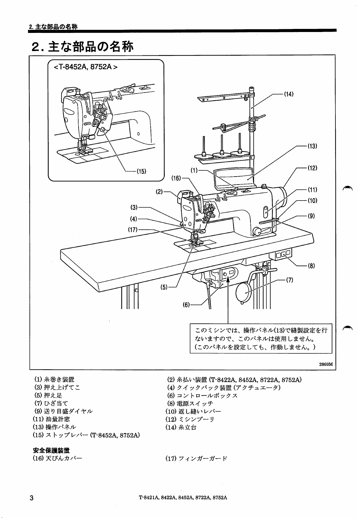
2.
2.
<T-8452A,
on
8752A>
0
(2) (T-8422A, 8452A, 8722A, 8752A)
(S)W:k.±ifX^
(5) X.JS
(7)r>$'^T
(9)
ill
19
(11)
(13)
(15) X h
(16)
yyuy<—
(T-8452A, 8752A)
T-8421A,
(4) X
(6) =i h D
(8)m^!^.>5.^
(10)
(12)
(14)
(17) y
8422A,
8452A,
—:y
5/f-
8722A,
(r^^3L:n—^)
8752A
2869M
Page 12
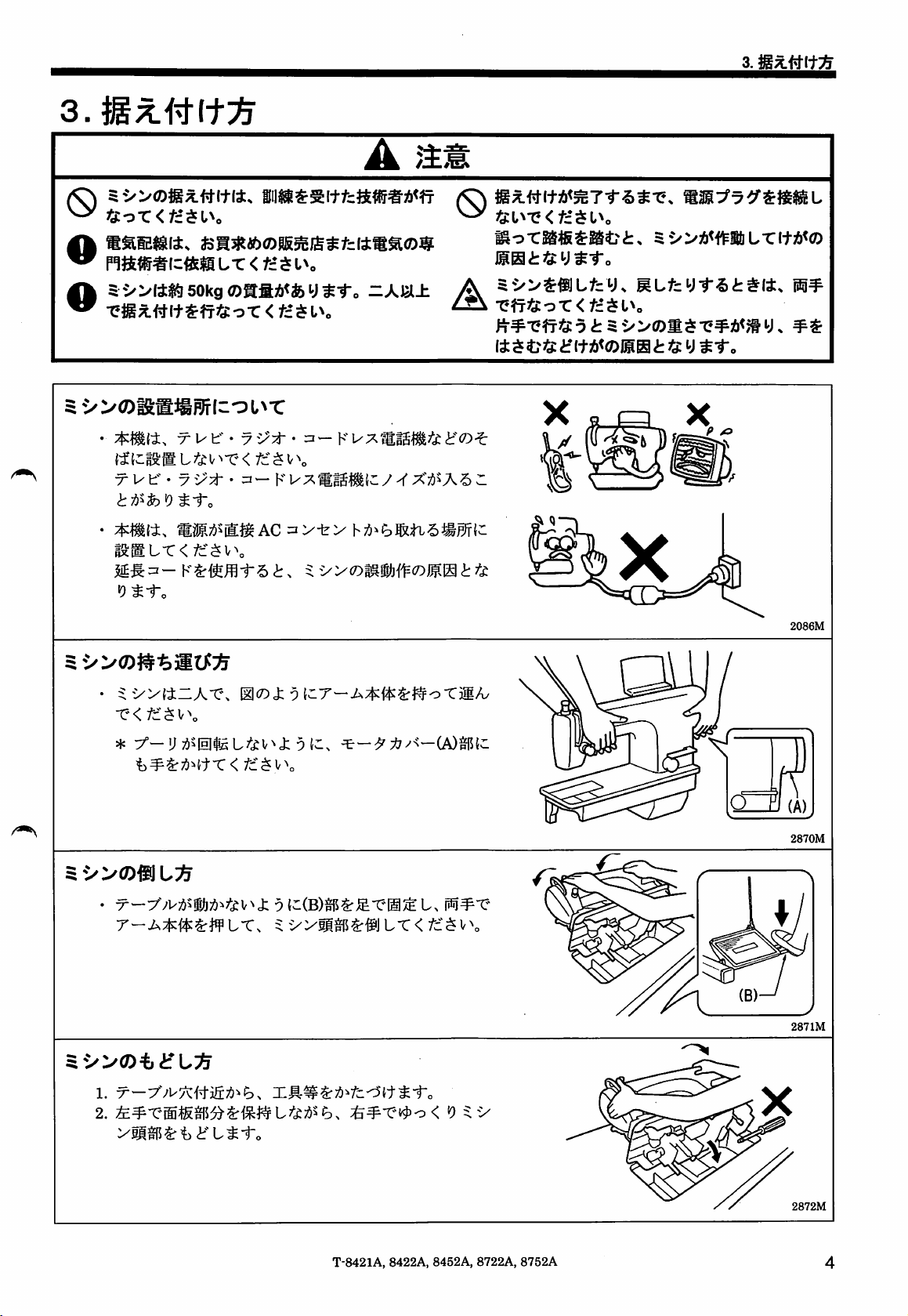
3.
0
'S:or<fc*$U,
na«#i=«EffiL-c<fc-su.
©5
5
'»l4«f|50kg®aSA<fcy$-r.
-ejijiwi+^ff'So-c
W(DiSg:®Rlrl-•^L^•C
•
(^lclS;BL^^cl<^•C•<
•r
ut"
• •
•
*«l±,
S9:BL-C<fc*$V\
i5
liS/iiitg^AC
41-„
A ^
iiisa$aitfca»#A<ff
-AUl±
<
fc'su.
K^;^fl;K^'fcif®-^•
fc*Sv\
3—
Ku-^fliaS^ty-I"X/jSASc:
3V-fe>
h7)>e>®ti.5»0flc
M.
Borasffisatri:.
iSHi'Sys-r.
,,
5-»SfflLfcy.
^ •eff)S:or<fc*su.
fi#-eff'S5t5-»®«s-e#A<jsy.
Ii S 4?jS:if(+A<®ISHi:jS y
5-»A<<^MLTItA<®
RLfcyf'5i:#tt.
S-r.
9
{-(B)§P^J£-ei§^
2086M
2870M
t.
i^^-e
287IM
T-8421A,
8422A,
8452A, 8722A,
8752A
2872M
Page 13
3.
3-1.
•
X—
t-c</c^v\
• > h •
-;u7t?
->^7
520.5
3-
80.6 , V
i
19.5
19.5
3-2.
1200
1.
•>
(1)
=ih
(2)
7}^VH-[3^]
(3)
i-y
(4)
(5)
J^^[3jg|]
2.
(6)
-Ty
(7)
hP—
P
h[3M
h
P
A-A
2873M
—5/
2091M
T-8421A, 8422A, 8452A, 8722A,
8752A
Page 14
(1)
A i
(1)
(2)
yfv;feC[2^]
3.
(2)-^
2092M
4.
asit
(1) sJM=^•i^(:fe)[2^li|]
giM^'A(^)[2fi]
(2)
(3)
(4) ^ V y —
/^\
2874M
T-8421A, 8422A,
8452A,
8722A,
2875M
8752A
5.li®t:>i?S(t=rA
(1)
(2) <
6.
(3)
siait
t>?±(f}f
viJgit
#'[4
*]
0'^±lflf
bit
JA[2e]
L^$
Page 15
3.
7.
(1) t
yi^[2M\
(2)
(3) ^ < lb
[n
t<
ib(3){i.
^X'Lo-f}^'OnhihAyX'<fd
il
^ "C
2876M
^jA
t.
^'yytm^mLfzt^(0
8.
^ixT V^ V^
2877M
(1)
(2)
if??^i:[2^]
9.3^3;^
(1)
^iL-^
[crajS]
ri'i^(2)[2{®]
?r
Lo;6^i9
J; 9
<!rlfi5J6#(tT<
7^5;
h(4)
;rc$
2878M
T-8421A,
8422A, 8452A,
8722A,
8752A
Page 16
1
0.
ut^^x
(1)
(2) h
2880M
2881M
L-"C"n/t
2879M
^ V
"^o
<U?±(f0
1. J:«9T{f
2.
#;t±(f-Cr(4)T?J¥;tJS&(5)^TJf^i-o
^-Tc
13mm
iUR
LTML^i-o
Xy
h(6)^Lo;6^«9^i?)^-ro
t3ii:(lO);65t>^±(f(7)J:'9±(C|i^
5mm
(DXi^^\Z.
l?f5:t3ii:(lO)^IiIL^-ro
^^X'O J: lf^:feC(lO)
h(9)^Lo75^i9lfi5J6^-ro
2882M
T-8421A, 8422A,
8452A,
8722A,
8752A
Page 17
3.
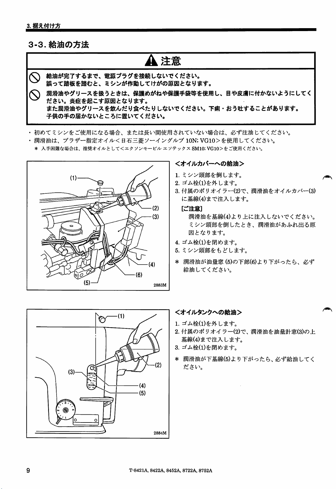
3-3.
(S)
0
fztsi\
^fzmmm'p<f
^^^0)^(7)ii36^^^:L^i:
*
t^it.
y-:^^&^/utzy^^tzy
Z 5
fc®
L^r<tz^l\
05H^y—r
LTCii^
Ltju^x<
yy>y
y^'^-f/Wznyx-y^^'X
tztsi\
ion;
1. ^
2.
3.
{^-^<7)71^V:t4
Tm-tsoet-r^z<tj&^fey^to
vGio>^^ffi
SM10;VGl0>?rr:'teffl<fc'^V\
(-Sl^(4)^
P^?ft^S/^(4)J:
5:
S dr
4.
5. 5:
*
tT<
B'pm\zm^t6ii^^o\zLx<
lt<
fc:^v^o
t^i"o
y—i2)X\
-e-^At^i'o
<9±{c:?iAt?'^v^-C<
PM;6Sfc^tL{±S'5i^
df^L^i-o
(5)(7)T^(6)J:i9T;6Sofc^.
(3)
;^c^v\
2883M
2884M
<:d--r;U^>^^(7)i^;'S>
2.Hm(D:r^V:tXy~(2)X\
pmiS^?ffifttm(3)(D±
^m(4)1^X^AL^iro
*
mmm:^^^rmm(6)x^r-f)>^fzh.i$^^-r'i^mLx<
/c$V\
T-8421A,
8422A,
8452A,
8722A,
8752A
Page 18
<4z5
3.
U^i"c
i
i
m m
T-8421A,
8422A, 8452A,
8722A,
n
8752A
Page 19
3.
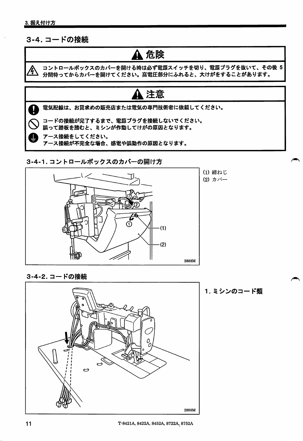
3-4.
A
O
3-4-1.
A
7-7.mm^Lx<fz^i\
(1) C
(2)
3-4-2.
2888M
n-KOgSi
1.
I
2889M
11
T-8421A,
8422A, 8452A, 8722A,
8752A
Page 20
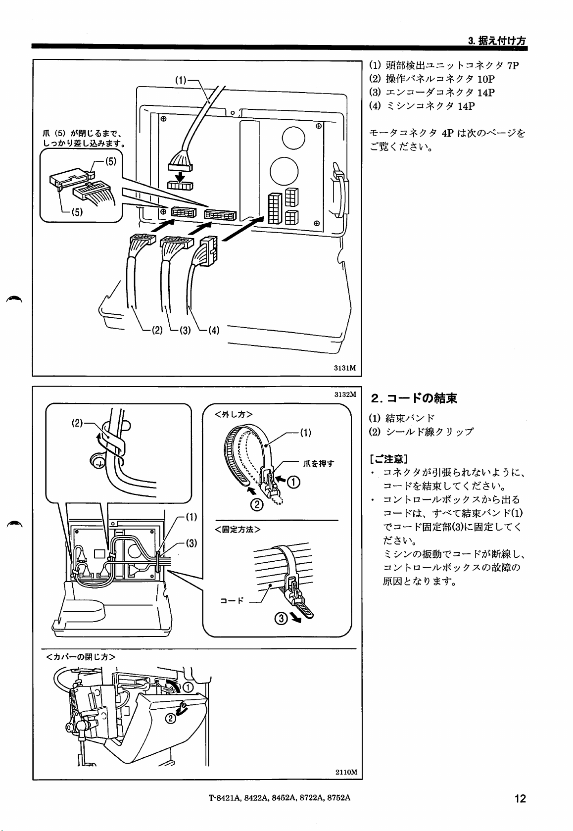
(1)
(2)
(3)
:x.i^^~-y^
(4)
IF
lOP
14P
14?
M
(5)
r N
\—f9^\—
(2)
^(3)
^(4)
<9\-Lyj>
®
4P
{tKk(0^—i>^
::n<fz^\^\
3131M
3132M
2.
=i-Ka)JiSS
<i2/<—0WiC'^>
=i-K
®V
m$}9-r
(2) V
=3—
K^Ji;S^L-C<
. n
:/h
p—/l^xK
=1—K(l)
KI§^^(3)tC@^LT<
^
^»'(Dmmx^=^-
3 > h p
—/WxK
^f^v\
y ^
y.(D^^$:(D
t.
2110M
T-8421A,
8422A,
8452A,
8722A,
8752A
12
Page 21
3.
h
* oiloa
2890M
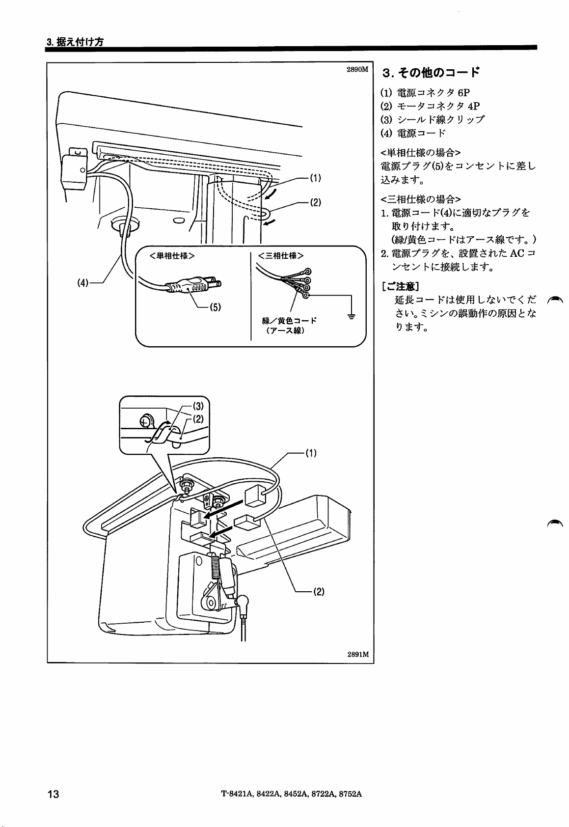
3.
(1)
(2)
(3) V
(4) K
<m^i±m(Dm^>
^{5)^^y±y
3A^^i-o
<~mii:m(Dm^>
[-aiS]
^;g:zi-
$1/\ 5:
"9^1-0
KMffl
yy<r)mw\\^(DWM
6P
4P
K
h
L/c^V^•X;<
L
(c
/c
t
2891M
13
T-8421A,
8422A,
8452A, 8722A,
8752A
Page 22
28g2M
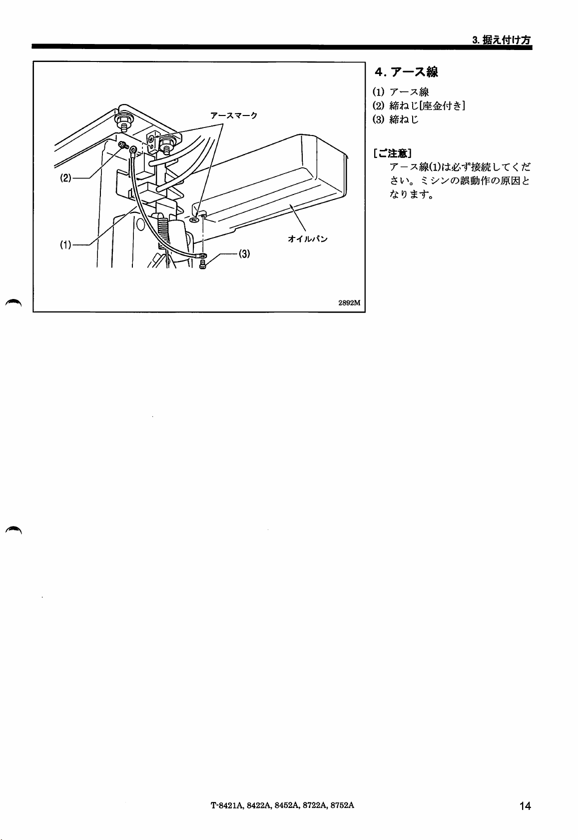
4.
T-
(1)
(2)
(3) C
T -
;^^(l){i£^-f
3.
LT
<
T-8421A,
8422A,
8452A,
8722A,
8752A
14
Page 23
3.
3-5.
IS^Ik
a<®»i=^*i.fcy.
ltA<.
Sfcli5-»©®ll®llHi:<£yS-r,
mm.
a-effLfcy
2114M
U'Su-e<fc*$i-\
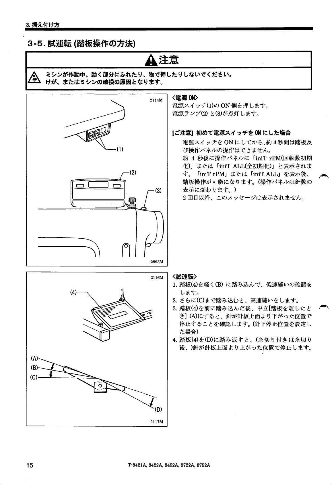
<®3iON>
fffo
4 TiniT
it)]
-To
2[H|g^(^,
y^(D<D
riniTrPMj
TiniT
L^-t-o
rPM(0aiJ],^
ALL(^^,^fb)j
TiniTALLj
5/ir—
2893M
2116M
2117M
1.
®ig(4)^^<(B)
t^-fo
4.
^^S(4)^(D){c:I®^iIi-^.
ik.
Ji:^>ofdM-e^ihl.^-ro
15
T-8421A,
8422A, 8452A,
8722A,
8752A
Page 24
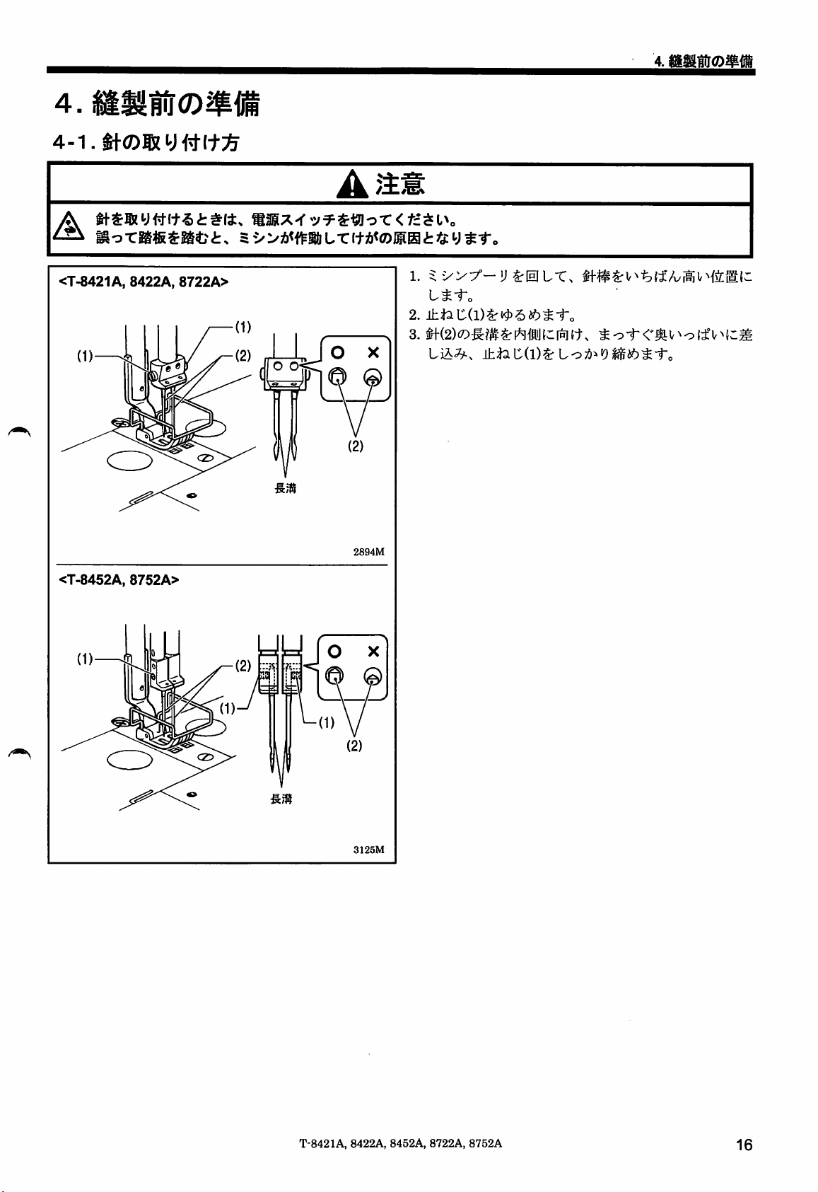
4.
A
^ 5->
<T-8421A,
<T-8452A,
8422A,
8752A>
8722A>
O O
an@
ur
itA<®BEgttty^-r.
O X
®
(2)
28g4M
L^-fo
LiA^y-,
3125M
T-8421A,
8422A,
8452A,
8722A,
8752A
16
Page 25
4.
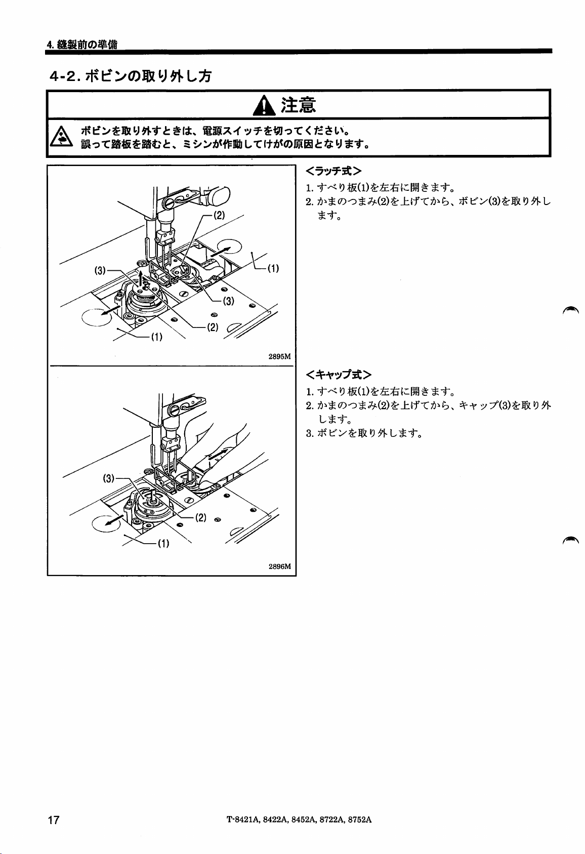
4-2.7Kt?>(7)ffiy^L^
A
A
o-CKfiSKfei:.
5
L.TI+)!i<©ISHi:<i:yS"T.
2895M
2.
^^:S(7)o^;^(2)^_h{fT:^i^^.
L^i-o
3.
ytsify^M^^L^iTo
=^-\'19
2896M
17
T-8421A,
8422A,
8452A,
8722A,
8752A
Page 26

4-3.
A
A
2897M
n
iftK
M<y.
tiTJff
sfctt5-»ro®«<DiiHt)S:y^-r.
Lfey
LiSI^T?<
1.
i~o
tztSl\
^^5SIStT</c
^¥^_h^fTc.-e±(f^i-o
ftA80%^-e(:iLT<
2123M
T-8421A,
2124M
8422A,
8452A,
8722A,
8752A
fc$v\
18
Page 27
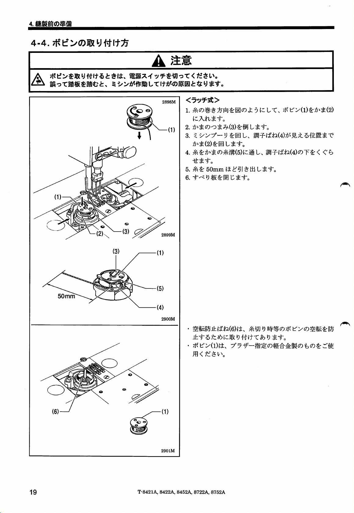
4-4.
A
2898M
1. i t*C>
(dAtv^-fo
2.
t^i-o
/Kt:-':/(l)^;^i^^(2)
4.
5.
6.
(3)
50
mm
2899M
2900M
50mm
fi
^1^ tU
m^{ti2(4)(Dr^<
L^i"o
<h
±-t6fcibl,Z^'0Hi^Xh'0^iro
-/yfiy(D^
2901M
19
T-8421A,
8422A,
8452A, 8722A,
8752A
Page 28

50
mm
50
mm
2g02M
1. 0
y(2){::AtL^i-o
2.
<A>
y(2)(i<A>
<B> <C>(D 3
^"t'o
2)^^^A(8){;iiiL.
<B>
<0
^•to
imn-^-To
3)7!^^:^
A(8){^j@
{-LT.
*9
^i'o
TEOcfcp
50mm{5i'§lttUL^-ro
50mm{J<lf51# HjL ^ "^o
5/
50
mm
3126M
3127M
3.
4.
5.
yy'{2)^f)^~^\CAtli^i-.
t^-f-o
(9)
(^5^
2903M
|5^±1-6/c
dSl19#ftT fo19^ 1~o
m<fz.^\^\
2904M
T-8421A,
8422A,
8452A,
8722A,
8752A
20
Page 29
4-5.
±^<0)1
m o
r®««Kfc
;->vy-!J^igL,
ltSrl»#*i1-„
:fc{RiJ<D^b
5fe
SSX-f<
t.
5 •>
>»
^0'A/(i)Srft±f4;stL-t*%aL-r<fcSv\
(-ii
L r </c$ V\
L T ItA<(!5HEatfty
«SIV
Sf.
^#aL^-f-<.
21
T-8421A, 8422A, 8452A, 8722A, 8752A
Page 30
4.
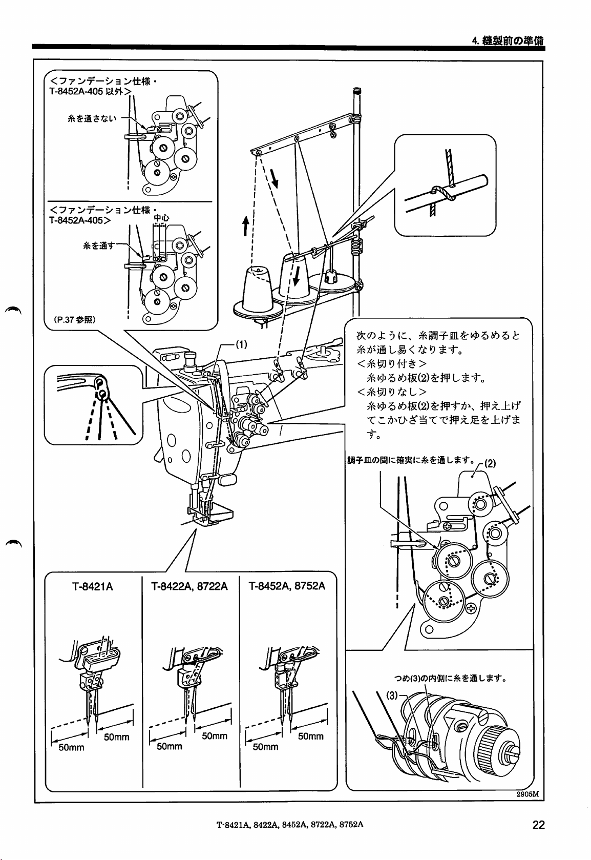
<:?7>"7—V
T-8452A-405
<:7T>x-va>tt^
T-8452A-405>
a
T-8421A
T-8422A,
8722A
T-8452A,
8752A
<^^•9
r r ;6^t> ^
T-e^f
;t
1-
|@^jni©r^ic5t^lz^$jiL^-ro
Oft(3)<Drt®JIC SiiL
^ ±Jf^
_(2)
50mm
50mm
50mm
50mm
T-8421A,
50mm
8422A,
50mm
8452A,
8722A,
8752A
2905M
22
Page 31

4.
4-6.
4-7.
(7)110!®^,^
2S06M
1.
(C0t-C.
•
3.
n
* 3^19
yi^L^-to
X2y^:^9\'l.t.'ro
mm'^m
^
-e^t?
mniLx<fz^\^\
y^
)
kM2)(D^^^k-^^hk(Dk\^\^
L0/0^19
i:fe(::lHjLT.
<h^5SI&Lr<
2907M
4-8^tLi^mm<D^i^i3
®
x^t-to
2908M
(^^y##(D^)
2909M
2209M
"Mu
2910M
23
T-8421A, 8422A, 8452A,
8722A,
8752A
Page 32

4.
4-9.
(T-8452A, 8752A)
cram)
c ® 5
•»11
5
•>i
TiH0^#f?±0:^^li^T^j:t><£l^-e
4-9-1.
m±
UTffiffl-r•5«^i4.
<
tztsl\
CO
JH
o
3128M
5
I
IL.
I
#1-
?S:y-^to
f-^ih L t r < fc $ V\
O
T-e^l^LT<;^c:$v\
o
O
<£>
>?.
h :y
:/!//•<—(1)^,
h(1)^,
GO
Rfig(;it^i"o
uras
ur
<«s
^ofc{5;®-e
l,000rpm
CO
u<
e
O
4-9-2.
3131M
CO
o
3129M
-fy-ya.
h :y
(2)^#t^1-o
l//<—(l){i.
g ^ i:
o:>\)L\
'to
3130M
1.5
140°
1.1
110°
3.2
2.1
1.6
1.3
100°
2.7
1.8
1.3
50°
40°
2
4.4
3.5
2.9
2.5
2.2
4.6
3.4
2.7
2.3
2.0
1.7
3
4
5
6
7
8
4.8
4.0
3.7
3.0
70°
4.6
3.5
3.0
2.8 2.3
2.2
1.9
1.6
1.8
1.5
3.8
2.5
1.9
1.5
1.3
2.2
1.5
120°
1.8
1.2
<fitil®i/4a)«^>
^J]
liv^:^;^40°
2.9mm
T-8421A,
8422A,
tffcfi
8452A,
6
8722A,
8752A
24
Page 33

5.
5.
5-1.
7
y^(Dh6^-nm
€IS^i:(ifcb^
16 15 4) 3
c
:}yj: <
LTv^^
:^c:$v\
ly-y-^nmr
(12 11
L^fc
/*N
(l)
^ ly0:7j^
A p_B O p D
SB88
(2) —
/TN
A
A A A
y y y y
(3)
Oa
m
(4)
^^±i6||V^dr-
Oa
(14) (17) (13) (5)
8888.:
/O^
•
A^—0~99^iiiPL^i-o
• S7
V^a t|-i5:(0- 99) ^
rcD:3f—^IfL.
•To
r^±i6^v^j
cD^\<^.'j:rL.
• B • c •
D.
99~o^i^{i'^t^i~o
BIJ
± V>b
yyXr\^.-nLX\^^^t^it.
^-f
(8) (7) (9)
ABCD;6\^,j:Tt.
e • f
o
Lt-To)
A • B • C • D
<!r
2137M
C'D
t^-to
2138M
Km^^nx
2135M
2136M
2139M
2140M
it
OFF^:^;OS-e#^i-„
(5)
Oa
yyX^'\'^.'}:JLX\^^6t^it^
7<-f A • B • C • D
$n-CV^6#ffc(0-99)^igicihi6liV^L^i-o
L^-To
25
T-8421A,
8422A, 8452A, 8722A,
8752A
A • B • C • D O 1
2141M
f--r
2142M
Page 34

(6)
(7)
(8)
(9)
'm
19
.
nMl
V^^#l-ic(l-1999)-C\
iV^^—
yyXi^'^^.-nLX\^^^t^it.
-1999)
LfXik.
g
{-f^±
L ^ -To
;^^-^V^(7)i^^^|^l9igL^-ro
yyX^\^.'nLX^^6t^it.
E
{;l|g^^tl•CV^'5tl-^(l-1999)^3gLi|i|V^L^-fo
5.
/Xym^E
{d^/Tc^ti-CV^-S
2143M
• F
2144M
2145M
(10)
(11)
(12)
(13)
(14)
(15)
AUTO(^-h)^-
Qi
lEI
©
§Z§)®
Ni#M1S|(l*-
\Q000
Ouuu
v\
Mt^-to
/<?-;^,s-f^-r^'^;l:Tt•rv^;5i:t(i, |g:ii(220rpm)^^:bL-Cl/^;^i-o ^
(^^19
##(7)^)
•
U±i$±L^Xo
i-yyAi»±LX^^?,t^,
S+o
r^t!
«9
l0^fii^^^i(^^
L-CV^-5 t #
xn^-iW-rmz,
L^-To
^iUit
rij
L^ir,
it.
-f^M'PLt.-to
2149M
2150M
<9
itU^tiotiX.
»^±Tii»A>i--i:/)>-c-t
2146M
2147M
2148M
2151M
2152M
2153M
2154M
(16)
^§
t
#L^-To
(P. 25
•"(•3)
(17)
RESET(y-fe5/
h)=^-
+°<P-25M)
T-8421A,
8422A,
8452A,
8722A,
8752A
#]f)
2155M
26
Page 35

5.
5-2.
T
1
Jl
II R
iff -
4'
°//
*
V
^/II
iiD
ii
r^
2giiM
ON
-i
'(j®
•=!>
T
A(0-99)
B(0-99)
2157M
<rji3S>
ON
i
ft-_hff±L^i"o
Ti
• A I A
!*•«*
!*•••
! 1 1
'V.*I
'v.*j
«VJIV1
C(0-99)
A
V
D(0-99)
(d;^).
2158M
2159M
if±-c
2160M
27
T-8421A, 8422A, 8452A, 8722A,
8752A
Page 36

5-3.
5.
2912M
1
2161M
ON
^T's
/TN
1 A
•V«I
A
1
1
VJ
Iv)
y
(1-19) X
T\
fi-±T^-(p.
(0-99)
1-1999
26^m)x^m'^Ltcimnx^w±
^1-0
2159M
2160M
<sil)^«Jy|col^T
c-^l^T>
AUTO
HH
<fr•^±to«ii,M=oi\r>
tfff
•
cBi
•
I®
{^m^)n^<D^)>
=3r-^1f
{t-e^^-||V>^iSit-T
*fIJj:»;®l.^if~
SI".
«±i6l|V^
0FFtLT/!i>?3aHtT<fc$l'\
ASr-SSi".
LT.
AUTO
L^-to
•
C-D
)
T-8421A, 8422A, 8452A, 8722A,
ON
LT,
(;>-^ CD >).
.i:.
Jt»»V^l»0g^O
8752A
NtdSS-TS
L.
< T
ti.
- i }4S-e#
1
28
Page 37

5.
5-4.
L.
r-5j
aT^::?'=eofci:#^^#^ilJ^tSrtT?'=^v^^•to
<^]]^fil©is^>
AI
___ZZ
m2
' L^-to
"(•~A)
(2
#j^>.jqi-r)
19.
!>
T^nn
Cjuu
u^tt^
.
w:wm?)iocoif^
RESET
2
n&i±nt
(2)
^-r.
2167M
2168M 2169M
Mr
$
•
1.
(
roj
i^T^i-(-^^•:^^)^^^l:\
2.
r-5j
3.
E^t5^^'A£i::<bi:'Ur
•
RESET
•
RESET
^-(2)^ft-f-i:.
^-(2)^
10^\-'^{^T^::i]^yy-^^TikcD^iU-^^
^->:-999
^'ydWm^L.
^
•X:-;^/>>
5
?^->>-{^^21^1
^
V)
=3
v(l);i5m^TE.
2Mffic^s^cit^^D^i-o
T-8421A,
8422A, 8452A,
Hj
•fo^^'>L"CV^#^i-„
V h
U^'t'o
L^-To
8722A,
)
^-To
8752A
L/.e</.C
<9
fcfc"LI@
Page 38

6.
6.
rr-c-iftefli-5)imi,
6-1.
^mtlttzibt
&m^Ain^£-ox<
(23) (21) (19)
tc^i,\
bfother
• o o
LOCK
(8)
(18)
(20)
(22)
:^n—h=3f—
MIEi^V^dr-
fl-±T=^-
(24) (18) (20) (22)
•
.
TX
TM7i.t.i~o
ti:or<b;65-e#^t*o
(250rpm)T'IIM
•
.
ylJ-^;/1f;t^v^:3r-(8)(7)y
# ^i±"Ayo
.
r4
=^y(2iU^MJLx\/^^
r^ffL^j-o
2i]-^
lOOrprnX^mmV^-to
L^i-o
affi#L
=^y{19Wj^nL.
5gU^V^(C7:^t9^•to
T <f£$
LNo
rX-=i'y{X9)i)^
MEUVMi-C
T4=='y(2iW
2171M
2172M
2173M
• i
•
nrr4=^y
T-8421A, 8422A,
(23);i5^:l:TLTV^6i:#(t.
-J-
(24);6\^'j:TLTV^§
8452A,
8722A,
8752A
±T'^±U^-fo
2207M
2208M
2174M
30
Page 39

6.
6-2.
B8B8
(-10-20)
2210M
1.
§f±T=3r-(l)^ff
t^i"o
2. 4
y^^{2)iiZ^^'X:^n.
(xx
3.
A^^c:{iV^-(3)^J¥LT.
ON
{z
0
xxj
^mimt
roj
-e-fo)
6-3.
"(O)
rd)
LOCK
IZOl>r
(2)
W
(1) ( ) (4)
iS<^C'S
brother
(£5)9
2913M
2212M
•
±^±i<LW.{'im
4.
ENTER
i"c
ON
1"o )
rti{-ij:i9.
^-{4)^
rioj
rm
<ti:^t.i~o
2
fm±W
fi,
ON
CiL^ci:
Kft.i-o(T4^
s
10
L^-To
#.LOCK(p
y(2W,^j):T
if
10°
2138M 2139M
^):^-(l)
LTV^;S
6-4.
RESET
ENTER
31
^-5r}fL/£iSib.
^-Sr»-ri,
TiniTALLj
1&
(3) (4) (5) (
9.m^^
-y^Sr
t*7SStl.
ON Ic
T-8421A,
Lil",
8422A,
FUNC(7
ENTER(:3^
MAXi-^
*
rtL^£Odr~{::ov^T.
tc^\^\
8452A, 8722A,
y^-)^-{4)
y ^
8752A
^)=^-(3)
t ^ o
61
#
1 #
L^-to
L^-to
il".
Page 40

7.
A
A
'
^ML
y
witrBa
5
e/>36<f^i[i
A
Lr
<
tz^i\
LTlt;b<(D]Segi:«:
y
^to
A
7-1.
^^4".
ifi^s
5i/>$iaL/cy.
i(l<SB^(wSHtLfcy.
^tzlt^iy>(D^m<om^ttj:^J^to
mLfz^)t^tt\ts
mvWLtz^)Ltj:l^V<tz^l\
m^vmj:z>x<tztsi\
2914M
2915M
1.
2.
T.^^^t^J{^5lv^-C.
T:^;^i5;^A-X{::<
i9t±}$tt
T-8421A,
2114M
2893M
8422A,
3.
5.
8452A,
Wi^.y
•to
8722A,
y^(i)(D
xX(2)t(3)/i\'^^Tt^i"o
8752A
oNimnL^-To
mm^ii^^^-to
32
Page 41

7-2.
2916M
2917M
<T^5^iLX-^<Dlil^^tl>
m(DXoK9
0°
0|a$-a:6^<b
2918M
33
T-8421A,
8422A,
8452A,
8722A,
8752A
Page 42

7-3.
•
3
2919M
2920M
1.
^V-^/L-n
Lt-fo
5/^
(3)^;&(C[h]
tr.
n-jO
3.
C(5)^{^5
w^-M7){::
4.
Ifi5:fei:(5)^l^i6-C.
-to
<ilSiil^^>
2.
-to
3.
mW:^i^^t-to
ttzltm
LI|V^
K/i^.^ h
^/c6^^-To
^^>'
1//N—(3)^:fe{C0L-C.
u/^—(2)^jfp
L^-fo
5/^^{6)^3S
h :y
T-8421A,
2921M
8422A,
8452A,
fi,
8722A,
K/l^;^ h
^itW:t-eT{ft
8752A
<;/^'?(6)^MLllV^
</c^
W<—;|S(7){^^
V\
34
Page 43

8.
8.
8-1.
IELl^i||L^g
-±^
-T^
0572M
<+A'^v:^5£>
0573M
0574M
-t^01^
•?•
2922M
t ^
<T^(D3i^>
A
9l-DX<tz^l\
SorKfiSaSti:,
roSHttcy^i".
C(l)^lHl
T^0i)i^^ii<-ri)
T^s(om=f-^^<t^
5e/>/)<f^l!lLTIf)!l<
LTW»
Li-t".
2923M
<±^a)5i^>
35
ri
2924M
T-8421A, 8422A, 8452A, 8722A, 8752A
1.
2.
h(2)^[HlL-CML^1-.
Page 44

8-2.
iELL^^l^S
at"
0894M
0895M
0896M
.1 I. I I
8-3.
Vx_
1 r
T—r
y y
0897M
l|L^gA<IS^Ta^'5
'j
47mm
2g25M
a®!®®
»LT<fc$VV
(Tmn
fc'^vv
1.
r}ffi^is®teCroiS$j
)
W»fcDoi^).•:^•y
2.
3.
i0»feDoi;Z(.-f
fflii
tsstc,
Kl)Sri^>5J6J1-»
C(2)^0LTl
•;/
KDSrSefeJ-to
^
mS.LX<
34mm
34mm
29mm
2926M
33-37mm
T-8421A,
2927M
8422A,
•
y
8452A,
U-xVi/3
8722A,
>9
8752A
33~37mm
V(l)^m
;0S^2p-ei-o
LL^
1-0
36
Page 45

OtV^—va>tt^-T-8452A-405
2928M
•to
:7T>-T-i/a>tt^-T-8452A-405
^
LT:fc#^-to
<:77>ir—va>ttli
•T-8452A-405>
:7r>-r-i/a>tt3|i
•
yry'f-^y3yi±^<D^iyyvh.
t #
•
liV^@:g$
^
2mm
•
T-8452A-405
J£i>T'C||
0
2g29M
37
T-8421A,
8422A,
8452A,
8722A,
8752A
Page 46

9.
9.
A
«
Si
m-oxmwu^tih.
^
fcStv
ifeftSEc-rHHtJfeys-r.
sfciH»»•¥>•yy-;^^l):^fc•yfi'<fcy
A5-»«fflLfcy,
9-1.SS©fc^A+l
>y9^$«!loT<fc*SU.
5-»A<<^8!lLTItA<©llHi:'S:ySf,
MUfcyr-St^tt.
5'yxnmtx^tf^y.
^7lc<
rSffiv>fc/ci<5
U!Eft^-c<K$tv
t«
•
W¥-C{T«i:oT<fSI,*.
^^{mus-EWomsitis.yt.t.
{cS0tT^^oT<
<m^>
1.
2.
3.
5.
^mLT.
" Vjaj/ -
2930M
ION;
VGlO>?r^ffitr<yc^v\
r .y y X
1.
mmm-Mnmi)(Drmmi2)x<ort^^r>x^^tL
h.
5
2931M
<mm>
2.
±;^;iSIEL<
(P.22
3.
^LliV'^^
SMIO;
VGIO
> ^
(P.9#fiSJ
jioTV^6;^)^«|gL^-f-o
L^'^o
r-ggffl
< fc ^ V\
2932M
T-8421A,
8422A,
8452A,
8722A,
8752A
38
Page 47

9.
9-2.
3002M
1.
2.
JKy
:^'i'7—
igIEIc»aL-C<fcSv^
2933M
i|s&U-C<yi:$V\
ion;
VGio>^i^ffiLT<:^c$v\
*
A^EIiT^e^i-n
1.
X •;/y y
5;
SMio;
2.
(P.9
#m)
3. ^
{±, tVL'
VGio
> ^ r.'{^ffl < fc $ v\
(l)(cS^(2)^-e?iAL^i"o
tti-o
39
T-8421A,
8422A, 8452A, 8722A,
8752A
Page 48

9-3,
'^f'J-X0MI&-GREASEUP;!)<«^$tlfcb
roREASEUPj
zOrtHStilP
lOOOO
UULOJ
mmiu.h
ABCD
"°
(-tS
1.
RESET
[w'ilfe]
TGREASEUPj
•
tgreaseupj
X(niM^n.
=^-(2)^^tpU^1-o
TErrlOOj
o
O
FUNC
^-f-o
yv-y<Dm^i^
t.
^
vrim^ry^£<>x<tL^\.\
vrm¥)^n^j:t^^i^X(Dii^-'^mm^mLx
5:
MAXALOCK
T-8421A,
8422A,
8452A,
8722A,
8752A
Page 49

9.
GREASE
(SA2694-001)
30
mm
l.f-n.—-^(0^1^15
® ^
2.
BZL-301
bfot^ ^
2934M
[-aic]
•
y7f-'-fl^(7)<GREASE
(SA2694-OOl)W0!)^i—:^>
• <
sa)^rL—•^>
•
<GREASE
(t.
r<
GREASE
$;H'"CVLi'fev'*'C<C
yg-Xli
r^ij-xsis
<tztsi\
GREASE
BZL-301
BZL-301
LX<fz^\^\
BZL-300(SA2355-001)
L/^v
</f^ V^
(SA2694-00l)#O^^-:/>
(SA2693-001)J
BZL-301
tmm
^v"^o
2935M
SI—
1.
2.
l$:j3tC(2)^^L^i-o
^y^^OFF
4.
(2)
l-L^-To
yj-x^#:A:icfc.SxtL^
niticjiA-r^o
i5^'y-x^#LiA;9.^-r„
5.
lfi5:taC(2)<DjilS(Cfo^tl/ci/'y
6.
[^1t{-LT.
t.i-0
j
R
s
s
sia
s
s
pmi
s
s
-d)
/f
^)
—®
Kk^-i>{C^i-r^X<Dmm^X
(2)
2936M
/^\
«9
^"t'o
^J
•
ll^l=t#(D^'y—xii^oL—XVi/^^j^L.
^rmx.
41
2937M
T-8421A,
•
a-<DX%
8422A, 8452A, 8722A,
i:yxvi^f^fc^ofc^v^y'y
)
8752A
Lo:^^'0^fz
—
x^^T
Page 50

9ct^:
^
ii''C\
t^-fo
^ y
—^
5-lOmm
9.
2g38M
^
*
mmz.
8888
"(•
t^j\.i3/^-izmm^^^^^^Lx<tztsi\
u
7-^^>
i^rEBSEUn
y*
i A p B C p D
J^BM88B88
A)
(2)
m
rl
<1^
® ^ ^
n n 1
0-0-®
/T\
/^
_ w
€
(6) (5) (7) (3)
(^
•)©
(p. 9
1.
ON{c
t^-fo
TGREASEUPj
2.
RESET
3.
LOCK
4.
FUNG
V|g;^(l)b:^fe"C
(xxx
5.
6.
ENTER(^V^-)=3r-(7)?r2#i^±#b^-ro
gV^y-y-'—;0'^n|y
iZ^t>V
=^-(2)^J¥
L^-fo
=^-(3)^2|:ybl-b#t^-To
L.
n 5' ^
dr-(5)^Jf
rn.l34xxxj
y
V=3p-(6)^J¥L^1-o
^ y(
-Y
ti~o
5-10mm
ftZt(3)(D±TSa
0 4
-Y
Txxxj
y
^"to
L^-To
2939M
foj
K
2940M
8.
-y^^oFFizLti-o
-c-f-o )
T-8421A,
8422A,
8452A,
8722A,
8752A
(^vrmmt^r
2139M
42
Page 51

10.
1
A
0.
(cLr<t£$l^o
/±.m
M<<DllSi:J5:y^-ro
^<td:^
'ptji<tjih
/}
294IM
[9-14mm
2942M
<i|i&jftiillsa)iS>
1. ^
i/:/eIgi5^|&JL^1-o
2.
C(l)^0
WiLti-o
1.
2.
-^nhi)^h^%'Q(D^
3.
4.
5.
6. ^
LTx
t-to
iyymum.x-^
^ ^
9~14mm
1
x\
sfm^'yy^mmL^iTo
<|g^sa)iiliT>
43
miE^m
T-8421A,
2943M
8422A, 8452A, 8722A,
2.
;t4'/^M;fel:(l)^0L-C.
<9
•fo
8752A
'9
t^-To
3lLT<
Page 52

^
A
1.
Am.
M
11.
zAjls.t^\z[t
Aftm©«ii=msx'f
^oTSSSSati:.
1
1-1.
1
I
Ib/c^v^
5
•>LT
fz
y.
^iit ^
X
Ki
{xmn
<tiii\
lt)!i<®HH
^5
(DM^^h(D:^^h^
^(Dmm^^mLx<fz:^\^\
T V^ ii:/u/?) ^?
h
y^<(D\iLW.^^<
^;=^=¥C>$)'54f
IE
t<
X-to
;tJ£tCi^5i^L-C</c^V\
LT<
LT</f^V\
/c$V\
18-22
35
*
^
•
0573M
0574M
tz^\^\
yX^^^LX<fz^V\
0977M
T-8421A,
8422A,
8452A,
8722A,
8752A
2g44M
37
44
Page 53

11.
tl-'vtrillo
r <
TV
^V-ti-^/J^
—
iy
HV N?t^t>'
2945M
t'h:d^:XXl'^fzt
W
:tJ±Xl
Jf
;t)±^
1
yy^J:i^(DiU'imV^XX<fz^l\
y^M*9if
?!)m}§
^TV
S7)>
#•
tcl(/9']!|5
t T <ti$1/\
^
^ -ti:^7^)\
$ < L r < /!:^^I \
IEL<fl-^IX'9#{tT<
t"C
< fc ^
^mw
LT<Ac
tT<Ac
^ V\
/AllXi9 fi'fec7:)f^afijrtiR{1A^:^t iiii^7:feiA
h
^
WKi)^ho:>X.^^^v)
Xuf-yi^B
yh<
li!^>JriililliKi
{:J:I&'9#;iT
AcV
-CliTFCA)\ Ife
<
Ac^i/\
^A\
tT<
Ac^V\
>9
yict" ^ -ti:^ A)\
1 7 > 7 ^1^:>C9i'f{C®t19#;t'C<Ac
xp
A^
—L-C<
#•
it
/j
1/\
^ V\
tr<Ac^v\
AcAsv^
tj:\^^X-tt\
'C <Ac^
$ V\
v\
fz^l\
16
18~22
36
*
*
37
*
*
36
)70
*
30
2946M
t\lLW±\<iMoyM^^^ii^S:o
-elf
$;ibtl'Cl^AJr^^i:
^u.^mM2)(DmmiL
® ^ L 'C <
l#co
fo ^
f#(DACV
«9
®
^J^-19
Ac:
$ V
jl
t T V^^
-C<Ac^ V\
/v
LX<fc^l\
LT<Ac^1/
isx+
31
*
2947M
\
1
u
2944M
45
T-8421A,
8422A,
8452A,
8722A,
8752A
Page 54

11.
—i/
5
36
6
7
Hv^-ftt
vj^
V_^
«9
^l;6SoV^-CV^6^#{i.
2948M
^ L T < $ V\
teLT<fc:$v\
#;tT
<
LT<^c^V\
V-
V-
O"
v_
S-
2949M
(f;j3Ly5.h5,/<(D{tLW^.
;ti
^PS
r\
^:xJ£:h^mMLX<
LT
< fc $ V\
^V>)iit^{i/L-foii<
LT<i^c
fz^\^\
X^^ti\iM<\^X<
$ V\
tc
tT<fc:^V\
*
35
35
*
*
36
26
37
36
8
^ V at)
<9
B#0
{c:
TtI^^
7}<
^'>-(7)^
2950M
2951M
Tjf
(7)015;^LT<
V\
•
7i<
/=*
2Q„/
19
T:^##fi(i80%^T'
{>lt-C<fc:^V\
^
Hi-fX
•
tg^(D7K
19fc
t:'':/(c:®i19#;t-C
^9
< ^ V\
< fc $ V\
2124M
18
19--20
19~20
T-8421A,
8422A, 8452A,
8722A,
8752A
46
Page 55

11.
_h^
•
X<tc^^\
10
0471M
^ii
L ^
^X.
X<tz^^\
Ai^tr^(Dmti^mmLx<
^®tf9
^7^l^
^®'9{f^3i:^
i^fzit.
IE t <
f|-^®i<9f^itT
r V^tit^/9\
IEL<
tz
LT<
$ v\
19•^<•f;a^^^L-cv^^it^/^)^
±^;65fc6^-ev^:^it
h
^/i5oV^-CV^:5gRp"p^®^^9#;tT<
'9
^it/ul^^o
<!::
<E'T'^V^T<
^/i5ov^-CV^6§^5p"p^®l^#;x-C<
Lx<fz^h\
tc$V\
<
tc$l/\
tc^V^
tc:^V\
16
18-'22
9
35
38
*
*
fz^\^\
*
37
11
^mti
•n.
/
12
LT{^1S^{^^JA^-e
19
(C^|v>tc'9jf
^
L-CV^;^it^}6\
>9
it
"fV
LT<
\
/
f|-1$:^^iIl^L•rv^;5i:
mWLX<fz:^^\
>—
/i.,Sx
i];(DW^t<W.7LX^^^X\
0469M
ON
\z
r3:/f>
n —/I^/K y ^ y.
(D^
L/c<9
^
tf$V\
tli.
m}^^^LX<tz^l\
L^-To
LTV^^ii•^;^l^
ittT^tfTC'f
>E^{ci1-/55g:
im^mVXlEL^Mtm^
16
*
*
^/ii^^i-ti/'CV^;^it
hi)\
mm^^WjhhX<fz
^ V
^*0
13
47
T-8421A,
8422A,
8452A,
8722A,
8752A
2952M
Page 56

13
11.
26
14
oT
15
L7t^V^
16
1-6
5:
9
y^^
rOREASEUPj
O^
LT.
yy'X^OFF{zLX<tc^\^\
26
mwMf£-^m<^j:^'x-r^\
mm
zi:/1^n —/I^/Jn y ^
ll^(-^LiA^T'<
^ V
=r:/
h p
^O
—y^
^?si§
L T </f^ V\
7>.
(D"^
/f
y.\^(D
2952M
3154M
\l
*
13
12*
40*
T-8421A,
8422A, 8452A,
8722A,
8752A
48
Page 57

1
1-2.
31 ^ — :n — K
Err
(ii§Si±)
Err
x-^
1
—3—
zilyhP—>;/
1.
^7—=1—ti~,
ii±tt^:i^'^o
<!r.=3
X V^ i-;i)^o
V h p
—/l^T}^'
y^7.(D
•p
^ A ^
>
Sit.
2198M
2199M
Err
(31V3I
y—)
Err
(^
3
—
4
^ p -/
ZI n
p:/
h
^
tl
—y
p—y
T V^
LjAAX
iir/u/O
< fc $ V\
^
yff^CO::r^y=i^-^'
^
y(D^~^
*
3155M
n
LoJ_
fl
t
12*
M
fe°J-
c-fl
3156M
^
13
mx-r
r.i:^?SISLr<
49
yOFF
T-8421A,
iz
/c^V\
8422A,
LX^i^yX-
8452A,
8722A,
V
^¥X0
8752A
L.
<0^X#6
2953M
Page 58

zcy—n—
Err
(ir—•7'r
^y^iW})
4
K
5
^
zi:/1>p
—/u-^y
^
iyym^^h
^ y^\H(D ^ ^
t^LX<
ti$
12*
V\
3157M
Err
(mi±p$T)
Err
A)
Err
5/
hoiy—)
Err
(f—5:
y-)
Err
6
8
13
21
100
(GrEASEUP)
%3
5>Jt^l±]l^L^c<!r
m:^X
=iy}>p—y
=I:yh
n—y
m^^c^LiA^-e<fc:^V^o
TGREASEUpj
mm:^X
tr.
#.
y^^AtiW.LX.
^
yp^(D
CN16
::(7)
y^^
J: 9
ON
ii^
{zL^^/uXLfzf)\
on{zlt<fc$v\
tT<fc:^v\
(•^''jrmm
*
3158M
3159M
inf£
40*
Err
(diP
101
SW
4)
±IBm^(Dx^-zi-
=iy
y^M)^
rV
ON
\zfi:-^X\^%^ht\
yXy^
T-8421A,
yZfyX
y^4^0FF{zLX<
fcl±lfa)l555J3l^crffiii<
8422A,
8452A,
8722A,
8752A
*
3160M
t£$t\
50
Page 59

T-8421A
TWIN
TWIN
TWIN
NEEDLE
NEEDLE
NEEDLE
LOCK
DIRECT
T-8422A
DIRECT
WITH
THREAD
T-8452A
DIRECT
STITCHER
DRIVE
WITH
T-8722A
DRIVE
DRIVE
TRIMMER
THREAD
LOCK
LOCK
SPLIT
STITCHER
STITCHER
NEEDLE
TRIMMER
BAR
TWIN
WITH
TWIN
NEEDLE
LARGE
NEEDLE
LOCK
DIRECT
HOOK
DRIVE
AND
THREAD
T-8752A
DIRECT
STITCHER
AND
THREAD
DRIVE
WITH
TRIMMER
LARGE
LOCK
SPLIT
STITCHER
TRIMMER
NEEDLE
HOOK
BAR
Page 60

Thank you very much for buying a BROTHER sewing machine. Before using your new machine, please read the safety
instructions
below
and
the
explanations
given in
the
instruction
manual.
With industrial sewing machines, it is normal to carry out work while positioned directly in front of moving parts
needle and thread take-up, and consequently there is always a
the instructions from training personnel and instructors regarding
that
you will know
1.
Safety
This instruction manual
safe
operation of this
indications
howtouse
indications
and
machine
DANGER
CAUTION
it correctly.
SAFETY
and
their
the indications
and
to prevent
The
instructions
The
instructions
equipment
meanings
and
symbols that
accidents
instructions
may
instructions
could
and
INSTRUCTIONS
are
and
injury to yourself or
which
follow
result in
which
surroundings.
deathorserious
follow
cause
danger
injury
of injury that
safe
and
usedonthe
this
term
this
term
when
canbecausedbythese
correct operation before operating the machine
machine itself
other
people.
indicate
indicate
using
situations
injury.
situations
the
are
provided in
where
where
ordertoensure
failuretofollow
failuretofollow
machineorphysical
Symbols
A
This symbol ( ) indicates
indicates
(For example,
the
natureofthe
the
symbol at left
something
caution
that
means
that
you should be careful of.
mustbetaken.
"beware
of injury".)
The
picture inside
suchasthe
parts. Follow
so
the
the
damage
the
to
triangle
0
O
This symbol ( ) indicates something
This
symbol
natureofthe
(For example,
( ^ )
thing
the
symbolatleft
indicates
that
mustbedone.
something
means
that
that
"you
you
you
must
must
must
make
not do.
do.
The
picture
the
ground connection".)
inside
the
circle
indicates
the
T-8421A,
8422A, 8452A,
8722A,
8752A
Page 61

2.
Notes
on
safety
A
DANGER
Wait at least 5 minutes after turning off the power switch and disconnecting the power cord from the wall outlet
before opening the face plate of the control box. Touching areas where high voltages are present can result In
A
severe
Injury.
Environmental
Use
the
sewing
from
sources
electrical
Sources of strong electrical noise may
problems
Any fluctuations In
should be within ±10% of
machine.
Voltage fluctuations which
may
cause
The
power supply capacity should be
the
o
requirements for
consumption.
Insufficient
problems
machineInan
of strong electrical noise
line
noiseorstatic
with
correct
operation.
the
the
problems with correct operation.
the
sewing
power
with
supply capacity may
correct
operation.
A
area
which Is
electric
power supply voltage
noise.
rated voltage for
are
greater
greater
machine's
CAUTION
free
such
as
cause
the
than this
than
power
cause
requirements
The
ambient
range
o
o
o
of 5°C to
Temperatures
may
cause
The
relative humidity
45%to85%
should
occurInany
Excessively dry or humid
formation may
operation.
In
the
event
and
disconnect
Lightning
operation.
temperature
which
problems
of an electrical storm, turn off
may
35°C
during
cause
the
cause
during
are
lower or higher
with
correct
should
use,
devices.
power
cord
should
use.
operation.
be within
and
no
environments
problems with correct
from
problems
be
within
the
dew
the
wall outlet.
with
the
than
this
range
formation
and
dew
the
power
correct
of
Machine Installation should only be carried out by
a qualified
(S)
Contact your Brother
electrician for
o
be
The
The
o
more
Do not
complete.
0
Is
depressed
Injury.
Turn off the power switch before Inserting or
Q
removing
control
Be
connection Is not
O
receiving a serious electric shock,
with
technician.
dealer
any
electrical work
done.
sewing machine
Installation should be carried out by two or
people.
connent
The
the
box
could
sure
to connect
correct
operation
weighs
the
power
machine may
by mistake, which could result In
plug, otherwise
result.
the
secure,
may
that
approximately 50 kg.
cord until Installation Is
operateIfthe
damage
ground. If
you run a high risk of
also
occur.
Installation
or a qualified
may
need
treadle
to
the
the
ground
and
problems
When
securing
excessivelyorfasten
otherwise
shocks
0
to
should
cannot
tilting It
A
only
when
0
theydonot
otherwise
vomiting
could
If using a work
be
move.
Use
both
back
one
head
may
may
get
caught.
Be
suretowear
handling
Furthermore, do not drink
under
any
and
Keep
the
the
cords,
do not
them
thereIsthe
occur.
table
securedinsuchaway
hands
or returning It to Its original position. If
handIsused,
cause
the
get
Inflammation
circumstances,
diarrhea.
oil
outofthe
danger
which
has
to
hold
the
the
your
hand
protective goggles
lubricating oil
Into
your
eyesoronto
can
result.
the
reach
bend
the
too
hard
with
that fire or electric
casters,
machine
weight of
to slip,
and
oil or
as
of children.
the
so
that
head
the
and
your
and
grease,sothat
your
eat
the
they
can
cords
staples,
casters
they
when
machine
hand
gloves
skin,
grease
cause
T-8421A,
8422A, 8452A,
8722A,
8752A
Page 62

A
CAUTION
Sewing
This sewing machine should only be
0
0
O
A
O
operators
in
safe use
The
applications
Be
machine.
Ifgoggles
needle
enter
Turn off
The
depressed
•
•
•
If using a work
should
cannot
who
beforehand.
sewing
other
suretowear
are
breaks,
your
eyes
the
power
machine may
by mistake, which could result in injury.
When
threading
When
replacing
When
not
the
machine
be
secured
move.
have
received
machine
should
than
sewing.
protective
not wom, there is the
partsofthe
and
injury
switch at
operate
the
needle
the
bobbin
using
the
unattended
table
which
in
suchaway
the
notbeused
goggles
may
the
and
machine
has
used
necessary
when
using
danger
broken
result.
following times.
if
the
needle
and
casters,
needle
treadle is
when
the
so
that
training
for
any
the
that
ifa
may
leaving
casters
they
by
A
Attach all
machine.
devices
Do not touch
objects
may
machine.
Use
tilting it
only
head
may
Ifanerror
or
power
dealer
If
the
nearest
safety
If
the
attached,
anyofthe
against
resultinpersonal
both
hands
back
or returning it to its original position. If
one
handisused,
may
cause
get
caught.
occursinmachine,orif
smells
are
switch.
or a qualified technician.
machine
Brother
devices
machine
injury may result.
the
to
your
noticed, immediately
Then
developsaproblem,
dealer
before using
is
used
moving
machine
injury or
hold
the
hand
contact
or a qualified technician.
partsorpress
while
the
machine
weightofthe
to slip,
your
the
sewing
without
sewing,asthis
damage
and
abnormal
nearest
head
machine
your
tum
contact
these
to
when
hand
noises
off
Brother
any
the
the
your
Tum
cleaning.
depressedbymistake,
Use
both
tilting it
A
only
one
head
may
may
get
off
the
power
The
machine
hands
back
or returning it to its original position. If
handisused,
cause
caught.
to
your
hold
switch
may
which could
hand
before
operateifthe
the
machine
the
weight of
to slip,
result
carrying
head
the
and
Cleaning
out
treadle
in injury.
your
is
when
machine
hand
Be
0
when
they
otherwise
Furthermore,donot
under
vomiting
Keep
Use
Q
by Brother.
suretowear
handling
do not
any
the
only
the
get
inflammation
circumstances,
and
diarrhea.
oil
outofthe
the
proper replacement partsasspecified
protective
lubricating oil
into
your
can
drink
reach
goggles
and
grease,sothat
eyesoronto
result.
the
oil or
eat
as
they
of children.
and
the
can
your
gloves
skin,
grease
cause
T-8421A, 8422A,
8452A,
8722A,
8752A
III
Page 63

S.Warning
labels
The followingwarning labels
Please
follow
the
instructions on the labels at all times when using the machine. If
difficult to read,
t ^
1
please
A
1A
DANGER
Hazardous voltage
cause
off
wait
injury.
main
Sminutes
Be
secure,
and
will
Turn
and
before opening this
cover.
AGEFAHR
Hochspannung
verletzungsgefahrl
Bitte
switch
hauptschalteraus
warten
bevorsia
abdeckung fiffnen.
sure
to connect the ground. If
you run a high risk of receiving a
problems with correct operation may
contact
A
schalten
sie5minuten,
diese
appear
your
/g
sle
den
und
on the sewing machine.
nearest
Brother dealer.
A /b 1
5»f=oT
ADANGER
Un voltage non
provoque
des
Eteindre I'interrupteuret
attendre5minutes
d'ouvrlr le
blessures.
capoL
the
APELIGRO
adapte
Un voltaje
puedeprovocarlas
heridas.Apagarel
interruptor principaly
avant
esperar
de
abrir
ground connection is not
serious
also
inadecuado
5 minutos
esta
cublerta.
electric shock,
occur.
antes
the
labels have
been
A ^
A
CAUTION
Movingparts may
Operate
Turn
threading, changing bobbin
and
Safety
(A) Finger
(B)
with safety devices.
off
main
needle, cleaning etc.
devices:
guard
Thread
take-up
removed or
iC.\
cause
switch
before
cover
are
injury.
Direction of
Oil
operation
pan
2867M
Control
box
IV
2083M
T-8421A,
8422A, 8452A, 8722A,
8752A
2868M
Page 64

1.
MACHINE
2.
NAMES
3.
INSTALLATION
3-1.
Table
3-2.
Installation
3-3.
Lubrication
3-4.
Connecting
3-4-1.
3-4-2. Connecting
3-5.
Test
4.
PREPARATION
4-1.
Installingthe needle 16
4-2.
Removing
4-3.
Winding
4-4.
Installing
4-5.
Threading
4-6. Adjusting
4-7.
Using
4-8. Using
(Models with
4-9.
Corner
5.
USING
SPECIFICATIONS
OF
processing
the
Opening
operation
the
the
the
the
the
the
knee
the
thread
MAJOR
cords
the
(Operating
bobbin 17
lower
bobbin 19
upper
stitch length 23
lifter
thread
PARTS
diagram
control
the
BEFORE
cords
the
box
cover
treadle)
SEWING....
thread
thread
wiper
trimmer only) 23
sewing method (T-8452A, 8752A) 24
THE
OPERATION
PANEL
CONTENTS
1
3
4
5
5
9
11
11
11
15
16
18
21
23
7.
SEWING
7-1.
Sewing
7-2. Backtacking 33
7-3.
Sewing
8.
THREAD
8-1. Adjusting
8-2. Adjusting
8-3. Adjusting
trimming
8-4. Adjusting
9.
CLEANING
9-1. Daily
9-2. Lubricating via
condensed
TENSION
the
the
the
(Models
the
cleaning
stitches
thread
presser
tension
foot
trailing length
with
thread
thread
take-up
procedures
the
oil
cover
pressure
after
trimmer
amount
thread
only)....36
(every6months)
9-3. Applying
appears
10.
ADJUSTING
LUBRICATION
11.
TROUBLESHOOTING
11-1.
Sewing
11-2. Error
grease-When
(Semi
dry
THE
code
displays
"GREASEUP"
specifications)
ROTARY
AMOUNT
HOOK
32
32
34
35
35
36
37
38
38
39
40
43
44
44
49
(BASIC OPERATIONS) 25
5-1.
Names
5-2.
Sewing
5-3.
Sewing
5-4. Using
6.
USING
and
start
fixed
the
THE
functions
and
end
stitches
lower
thread
OPERATION
backtack
counter
stitches
PANEL
(ADVANCED OPERATIONS) 30
6-1.
Names
6-2. Adjusting
6-3. LOCK
Resetting
6-4.
and
functions
the
needleupstop
key
all
settingstotheir
position 31
defaults
25
27
28
29
30
31
31
T-8421A,
8422A,
8452A,
8722A,
8752A
Page 65

1.
MACHINE
1.
MACHINE
SPECIFICATIONS
SPECIFICATIONS
BROTHER
INDUSTRIES.
T-8421A-T03
ABC
Rotarv
hook
LTD.
D E F
Standard
hook
Large
hook
Quick
Thread
Lubncation
reverse
wiper
tvoe
For
Minimum
foundation
lubrication
For light-weight
medium-
weight
and
materials
3
Semi
For
heavy-weight
d
materials
T-8421A,
8422A,
8452A,
8722A.
8752A
Page 66

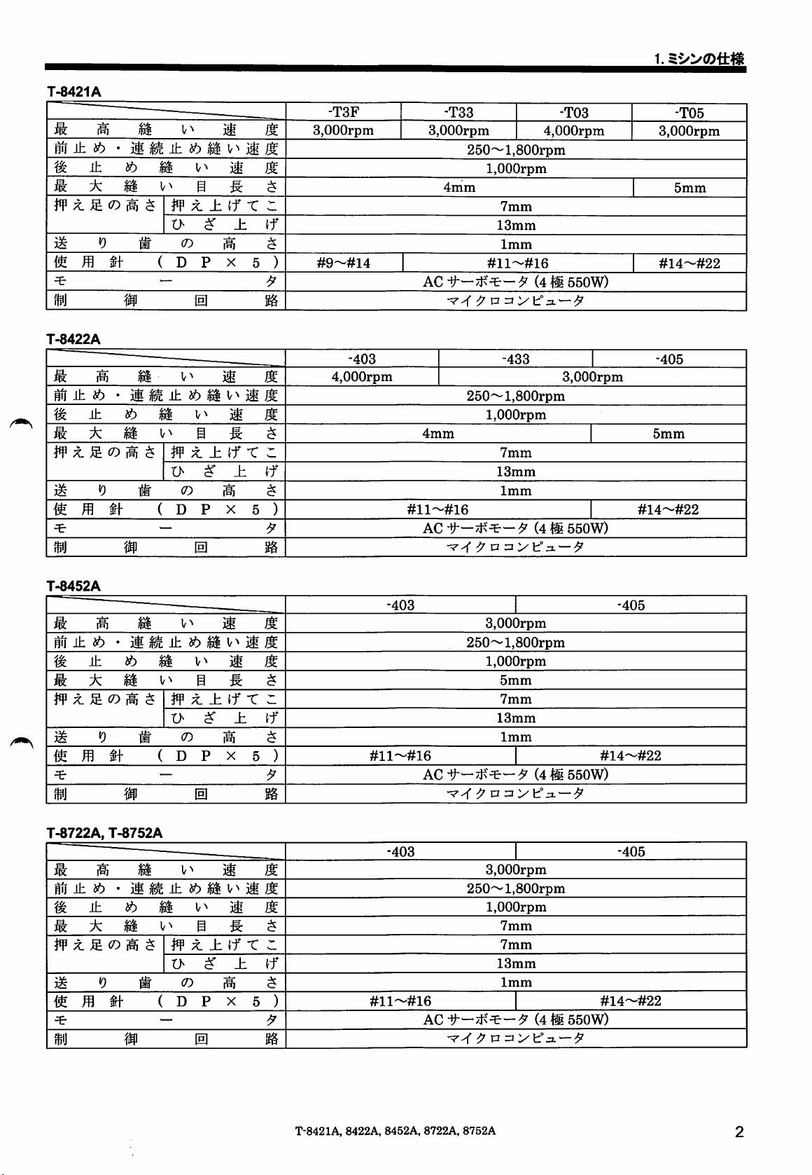
T-8421A
Max.
sewing
Start
backtacking
End
backtacking
Max.
stitch
Presser
height
Feed
dog
Needle
Motor
Control
T-8422A
Max.
sewing
Start
backtacking
End
backtacking
Max.
stitch
Presser
height
Feed
dog
Needle
Motor
Control
speed
backtacking
speed
speed
length
foot
height
(DPx5)
circuit
speed
backtacking
speed
speed
length
foot
height
(DPx5)
circuit
Lifting
Knee
Lifting
Knee
and
lever
lifter
and
lever
lifter
continuous
continuous
-T3F
3,000
#9-#14
-403
4,000
rpm
rpm
1.
-133
3,000
rpm
250-1,800
1,000
rpm
4,000
rpm
MACHINE
-103
rpm
SPECIFICATIONS
3,000
4 mm 1 5 mm
7
mm
13
mm
1
mm
AC
servo
motor
Microprocessor
250-1,800
1,000
#11-#16
(4-pole,
-433 1
rpm
rpm
550W)
3,000
rpm
#14-#22
-405
4 mm 1 5 mm
7
mm
13
mm
1
mm
#11-#16 #14-#22
AC
servo
motor
(4-pole,
Microprocessor
550W)
-105
rpm
T-8452A
Max.
sewing
Start
backtacking
End
backtacking
Max.
stitch
Presser
height
Feed
dog
Needle
Motor
Control
T-8722A,
Max.
sewing
Start
backtacking
End
backtacking
Max.
stitch
Presser
height
Feed
dog
Needle
Motor
Control
speed
backtacking
speed
speed
length
foot
height
(DPx5)
circuit
8752A
speed
backtacking
speed
speed
length
foot
height
(DPx5)
circuit
Lifting
Knee
Lifting
Knee
and
lever
lifter
and
lever
lifter
continuous
continuous
-403 1 -405
3,000
rpm
#11-#16
_yinQ
-4UO
#11hIS^16
AC
AC
250-1,800
1,000
servo
motor
Microprocessor
3,000
250-1,800
1,000
servo
motor
Microprocessor
5
7
13
1
7
7
13
1
rpm
mm
mm
mm
mm
(4-pole,
1
1
rpm
rpm
mm
mm
mm
mm
(4-pole,
rpm
#14-#22
550W)
rpm
#14-#22
550W)
ylHK
-4UD
T-8421A,
8422A,
8452A,
8722A,
8752A
Page 67

2.
NAMES
2.
NAMES
OF
MAJOR
PARTS
OF
MAJOR
PARTS
<T-8452A,
8752A
>
Bobbin
(1
Lifting
(3
Presser
(5
Knee
(7
Stitch length dial
(9
(11
Oil
Operation
(13
(15
Stop
Safety
devices
(16)
Thread
winder
lever
foot
lifter
assembly
gauge
window
panel
lever (T-8452A. 8752A )
take-up
cover
T-8421A,
The
settings
using
the
used.
(Settings
machine
for this
operation
made
operation.)
sewing
panel
(13),
using this panel will not affect sewing
(2) Thread wiper (T-8422A, 8452A, 8722A. 8752A)
(4) Quick reverse (Actuator)
(6)
Control
(8)
Power
(10)
Reverse
(12) Machine pulley
(14)
Cotton
(17)
Finger
8422A,
8452A,
8722A,
box
switch
lever
stand
guard
8752A
machine
andsothis
are
carried
panel
out
is not
2869M
Page 68

3.
INSTALLATION
A
CAUTION
3.
INSTALLATION
Machine installation should only be carried out by a
Q
qualified technician.
Contact your Brother
for
O
O
About
• Do not
• The sewing machine should be plugged directly into an AC wall
Carrying
•
The
any
electrical work that may
The
sewing machine weighs approximately 50 kg.
The
installation should be carried out by two or
people.
the
machine
set
up this
sewing
televisions, radios
equipment
sewing
outlet. Operation problems may result if extension
used.
showninthe
* Hold
not
machine.
the
machine
the
rotate.
may
be affected by electronic interference from
machine
should be carried by
illustration.
motor cover (A) by
set-up
or
dealer
machine
cordless
or a qualified electrician
need
to be
done.
more
location
near
other
equipment
telephones,
the
hand
alsosothat
arm
otherwise
by two
the
such
cords
people
pulley
0
A
such
the
are
does
Do not
complete.
depressedbymistake,
Use
tilting it
only
head
may
as
as
connect
The
both
hands
back
one
handisused,
may
cause
get
caught.
the
power
cord until installation is
machine
or returning it to its original position. If
may
operateifthe
which could result in injury.
to
hold
the
machine
the
weightofthe
your
hand
to slip,
and
treadle
head
machine
your
when
hand
2086M
is
Tilting
• Hold
Returning
1.
2. While holding
section
and
then
head.
Clear
machine
back
push
the
away
headtothe
the
(B) with
the
machine
any
tools,
the
machine
your
arm
head
footsothat
with both
headtothe
etc.
which
face
plate with
upright position with
the
table
hands
to tilt
upright
maybenear
your
left
hand,
your
T-8421A,
back
the
right
does
the
table
gently
hand.
8422A,
not
move,
machine
position
holes.
retum
8452A,
the
8722A,
2870M
287IM
2872M
8752A
Page 69

3.
INSTALLATION
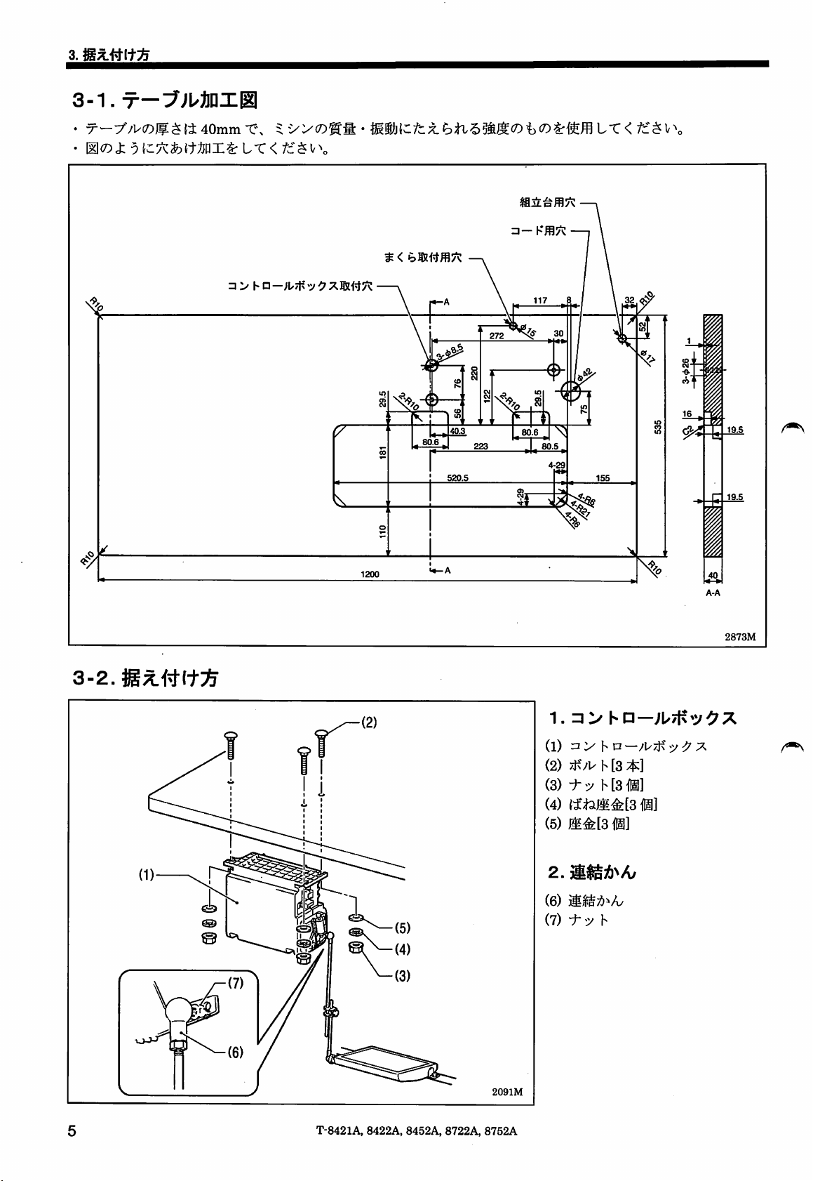
3-1.
Table
The top of
vibration of
Drill
holesasIndicatedInthe
processing
the
table should be 40 mm in thickness and should be strong enough to hold
the
sewing
machine.
diagram
Illustration
below.
Head
rest
hole
Cotton
stand
Cord
Control box mounting hole
cr
60.6.
520.5
hole
60.5.
hole
4-29
the
weight and with-stand the
I
1
16
19.5
#1
3-2.
(L
Installation
1200
1.
Control
(1) Control box
(2) Bolts [3 pcs]
(3) Nuts [3 pcs]
(4) Spring
(5)
Washers
Z
Connecting
box
washers
[3 pcs]
(6) Connecting rod
(7) Nut
i
2873M
[3 pcs]
rod
2091M
T-8421A,
8422A,
8452A,
8722A,
8752A
Page 70

Operator
(1)
3.
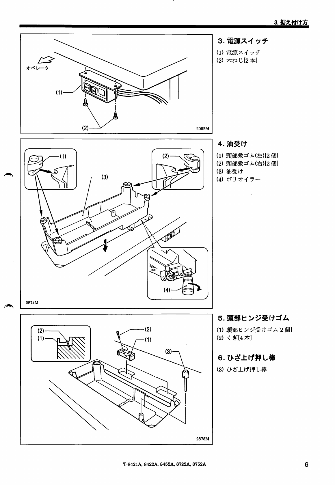
(1)
(2)
Power
Power
Screws
switch
switch
[2 pcs]
3.
INSTALLATION
(2)—^
2092M
4 Oil
(1) Head cushions (left) [2 pcs]
(2)
(3) Oil
(4) Oiler
Head
pan
cushions
pan
(right) [2 pcs]
2874M
T-8421A, 8422A,
8452A,
0
8722A,
2875M
8752A
5.
Rubber
(1)
Rubber
(2) Nails [4
6.
Knee
(3)
Knee
cushions
cushions
pcs]
lifter
liftercomplying
[2 pcs]
compiying
bar
bar
Page 71

3.
INSTALLATION
2876M
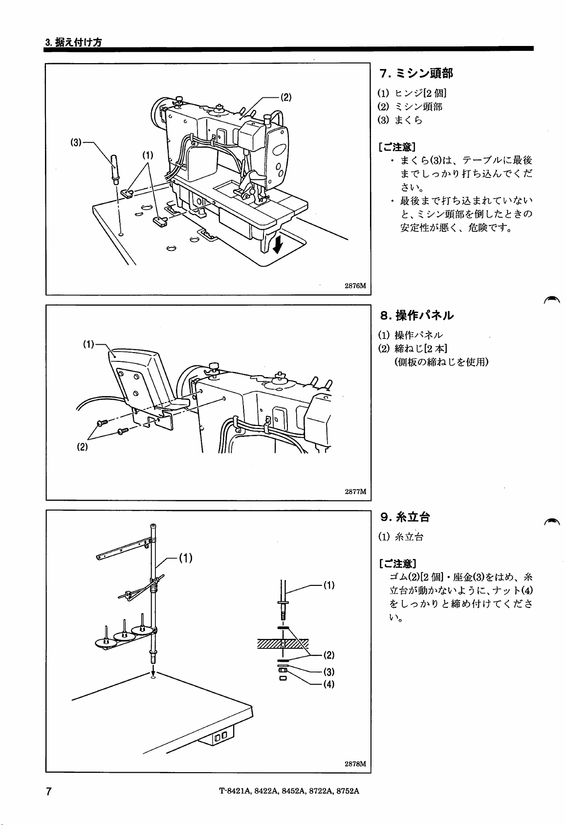
7.
Machine
(1)
Hinges
(2)
Machine
(3)
Head
NOTE:
Tap
the
the
table
not
pushedinas
machine
stable
8.
Operation
(1)
Operation
(2)
Screws
(Use
head
[2 pcs]
head
rest
head
rest
hole. If
head
will
whenitis
tilted
panel
panel
[2 pcs]
for tightening
(3)
securely
the
head
rest
farasit will go,
notbesufficiently
back.
rear
cover)
into
(3) is
the
T-8421A,
8422A,
8452A,
8722A,
2877M
2878M
8752A
9.
Cotton
(1) Cotton
NOTE:
stand
stand
Securely tighten the nut (4)sothat
the
two
rubber
washer
so
that
move.
(3)
the
are
cotton
cushions
securely
stand
(2)
and
clamped
(1)
does
the
and
not
Page 72

2879M
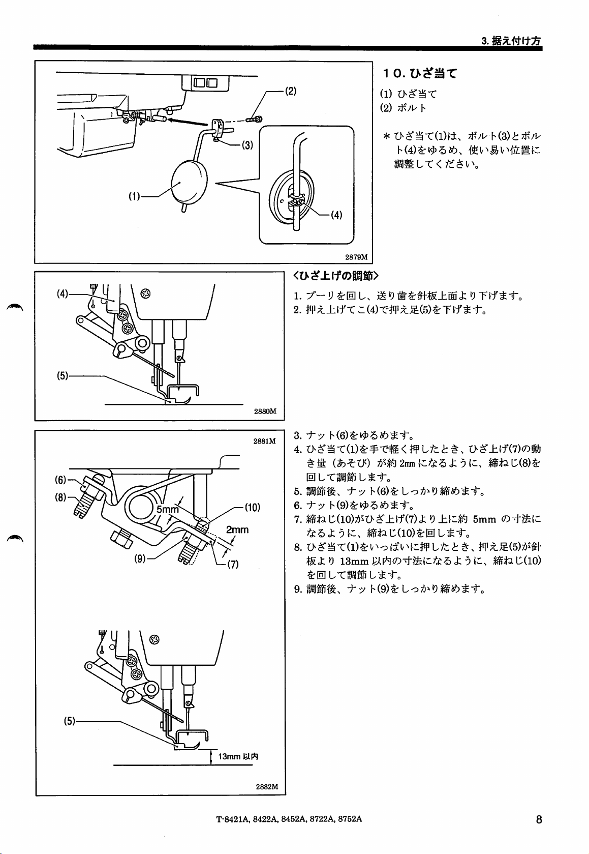
10.
Knee
(1)
Knee
(2) Bolt
*
Loosen
and
a position
lifter
move
lifter
the
where
plate
bolt (3)
the
3.
INSTALLATION
plate
and
knee
lifter
it is
easytouse.
the
plate
bolt (4),
(1) to
V>
2880M
2881M
<Knee
1. Turn
2. Lower
3.
4. Turn
lifter
the
topofthe
the
Loosen
the
the
knee
adjustment>
machine
needle
presser
the
nut
screw
lifter (7) is approximately 2 mm when
lifterplate (1) is gently
5.
Securely
6.
Loosen
7.
Tum
the
mm.
8.
Tum
the
screw
the
tighten
the
nut
screw
(10)
adjusting
foot (5) isatthe
mm of
fully
9. After
(9).
the
needle
pressed.
adjustment
pulleysothat
plate.
foot (5) by using
(6).
(8) to
adjustsothat
pressed.
the
nut (6).
(9).
(10) until
and
desired
the
screw
plate
the
knee
(10) to
when
position within a
is completed,
the
feed dog is below
the
liftinglever (4).
the
amount
distance
lifter (7) is approximately 5
between
adjustsothat
the
knee
securely
the
distance
liter
plate
tighten
of play in
the
knee
the
end
presser
of 13
(1) is
the
the
of
nut
Within13mm
2882M
T-8421A,
8422A, 8452A,
8722A,
8752A
8
Page 73

3.
INSTALLATION
3-3.
Lubrication
A
CAUTION
Do not
0
treadleisdepressed
Be
0
into
Furthermore,
diarrhea.
Keep
The
sewing machine should always be lubricated
after
long
Use
only the lubricating oil (Nisseki Mitsubishi Sewing Lube ION;VG10) specified by Brother.
* Ifthis type of lubricating oil is difficultto obtain, the
connect
suretowear
your
the
periodsofnon-use.
the
protective
eyesoronto
do
not drink
oil
outofthe
power
cord until lubrication
has
been
by mistake, which could result in injury.
your
reach
goggles
skin,
the
and
otherwise
oil or
of children.
gloves
inflammation
eat
the
and
recommended
when
handling
can
grease
under
the
oil supply replenished before it is
oilto
<Lubr!cating
1.
2.
3.
completed, otherwise
the
lubricating oil
result.
any
circumstances,asthey
use
is <Exxon Mobil
via
Tilt
back
the
machine
Remove
Use
oil
the
cover
the
rubber
accessory
(3) until
(4).
NOTE:
Do not
fill
with lubricating oil
If you
pourintoo
when
the
machine
4.
Replace
5. Return
* If
oil
the
rubber
the
machine
the
lubricating oil level
gauge
window (5),besuretoadd
the
the
the
machine
and
grease,sothat
can
used
Essotex
oil
cap
oiler (2) to
cover>
head.
(1).
oil level
SM10; \/G10>.
pour
reaches
past
much
lubricating oil, it
headistilted
cap
(1).
head
to its original position.
drops
below
may
operateifthe
they
do not
cause
vomiting
for the first time,
lubricating oil into
the
reference
the
reference
may
back.
the
bottom (6) of
more
oil.
get
and
and
line (4).
spill
also
the
line
out
the
2883M
2884M
<Lubricating
1.
Remove
2.
Use
the
gauge
Replace
3.
* If
the
line (6),besuretoadd
via
the
rubber
the
accessory
oil level
reaches
window (3).
the
rubber
lubricating oil level
the
oil
tank>
cap
(1).
oiler (2) to
the
cap
pour
top reference line (4) of
(1).
drops
below
more
oil.
in lubricating oil until
the
oil
the
bottom
reference
T-8421A,
8422A, 8452A, 8722A,
8752A
Page 74

•
Lubrication
Apply
1-2
drops of oilto the places indicated by the arrows.
3.
INSTALLATION
<Senii
dry
type
and
minimum
lubrication
type>
<T-8452A,
8752A>
i
m
n
T-8421A,
8422A,
8452A,
8722A,
8752A
Page 75

3.
INSTALLATION
3-4.
Connecting
Wait at least 5 minutes after turning off the power switch and disconnecting the power cord from the wall outlet
before opening the face plate of the control box. Touching
A
severe
Contact your Brother
o
Do
The
(S)
Be
electric
o
injury.
not
connect
machine
suretoconnect
shock,
the
may
and
the
cords
dealer
or a qualified electrician for
power
cord
operateifthe
the
ground. If
problems
with
A
A
until all
cords
have
treadleisdepressed
the
ground connection is not
correct
operation
DANGER
areas
where high voltages
CAUTION
any
electrical work
been
connected.
by mistake, which could result in injury.
secure,
may
also
occur.
that
may
you run a high risk of receiving a
need
are
present can result in
to be
done.
serious
3-4-1.
3-4-2.
Opening
the
Connecting
control
the
cords
box
cover
(1)
Screw
(2) Cover
1.
Sewing
machine
cords
2889M
11
T-8421A,
8422A,
8452A,
8722A,
8752A
Page 76

3.
INSTALLATION
Pushinsecurely
the
tabs
(5)
engage.
r
until
(1) 7-pin
(2) 10-pin
(3) 14-pin
(4) 14-pin
Refer to
motor
connector.
head
operating
encoder
machine
the
following
detector
panel
connector
connector
unit
page
connector
connector
for
the
4-pin
1
<Removal>
<Securing>
Cords
(Dv
Press
the
tab.
3131M
3132M
2.
Repeat
(1)
Repeat
cable
cable
tie
tie
(2) Wire clip
NOTE:
• Bind
• All
the
cordsinsuchaway
connector
control
cords
does
not
get
that
come
box
shouldbesecuredtothe
cord holder (3) using
pulled out.
out
from
the
cable tie (1), otherwise vibration from
the
sewing machine may
cords
which
operation of
to
can
become
cause
the
problems with
control box.
cause
disconnected,
that
repeat
the
the
the
the
<Closing
the
cover>
T-8421A, 8422A, 8452A, 8722A,
2110M
8752A
12
Page 77

3.
INSTALLATION
^
<Single-phase>
???.
,0000
<Three-phase>
Green
and
(ground wire)
yellow wire
2890M
3.
Other
(1) 6-pin
(2) 4-pin
cords
power
motor
supply
connector
(3) Wire clip
Power
(4)
<For
Insert
wall
<For
1. Attach
cord
single-phase
the
power
outlet.
three-phase
an
specifications>
appropriate
power cord (4). (The
yellow wire is
2. Insert
the
the
properly-grounded AC
NOTE:
Do
not
use
othenwise
problems
may
machine
result.
connector
specifications>
cord plug (5) into a
ground
plug to
green
wire.)
the
and
plug into a
power
supply.
extension
cords,
operation
2891M
13
T-8421A, 8422A, 8452A, 8722A,
8752A
Page 78

Ground symbol
2892M
3.
INSTALLATION
4
(1)
(2)
(3)
NOTE:
Ground
Ground
Screw
Screw
Always
wire
[With
be
wire
washer]
sure
to
connect
ground wire (1), othen/vise problems
may
occur
with
sewing
operation.
the
machine
T-8421A, 8422A,
8452A,
8722A,
8752A
14
Page 79

3.
INSTALLATION
3-5.
Test
operation
(Operating
the
treadle)
A
CAUTION
« Do not touch any of the moving parts or press any objects against the machine while sewing, as this may result in
A
personal
injury or
damagetothe
machine.
2114M
<Turningonthe
Press
theONpower
The
power
NOTE:
When
The
treadle
approximately four
turned
After approximately 4
initialization) or "iniT
displayedonthe
ALL" is displayed,
operation
This
message
times
that
power>
indicator (2)
turning
and
on.
panel
the
power
switch (1).
and
the
the
seconds
operation
the
will
changetothe
will
not
(3) will illuminate.
power
switchonfor
operation
ALL"
appear
switch is
panel
after
seconds,
(full initialization) will
panel.
treadle
the
turned
the
first
time
will
not
operate
the
power
switch is
"inlT rPM"
After "iniT rPM" or "iniT
can
be
operated.
stitch
number
second
and
on.
(speed
(The
display.)
subsequent
for
be
2893M
2116M
2117M
<Test
operation>
1.
Check
that the machine
treadle (4) is gently
2.
Then
check
that it
(4) is gently
3. After pressing
needle
treadle (4) is retumed to
needle
the
4. If
pressed
the
is lowered to the top of
down stopping
treadle (4) is
sews
at low
speed
when
pressed
sews
treadle (4) forward, check that
to position (B).
at high
to position (0).
the
the
neutral position (A), (when
has
been
set.)
pressed
to position (D), (thread
speed
when the treadle
needle plate when
trimming is carried out for models with thread trimmer)
and
the
needle
rises
above
the
needle
plate
and
stops.
the
the
the
15
T-8421A,
8422A, 8452A,
8722A,
8752A
Page 80

4.
PREPARATION
4-1.
Installing
A
Turn
off
The machine may operate ifthe treadle is depressed by mistake, whichcould result in
the
power
the
needle
switch
before
BEFORE
A
CAUTION
installing
the
needle.
SEWING
4.
PREPARATION
injury.
BEFORE
SEWING
<T-8421A,
<T-8452A,
8422A,
8752A>
G
8722A>
Long
groove
2894M
1. Turn the machine pulley to move the needle
highest
2. Loosen
3. Insert the needle (2) straight in
long groove is facing inward, and then securely tighten the
screws
position.
the
screws
(1).
(1).
as
farasit
bar
willgoso
to its
that the
Long
groove
T-8421A,
3125M
8422A,
8452A,
8722A,
8752A
16
Page 81

4.
PREPARATION
4-2.
Removing
BEFORE
the
SEWING
bobbin
A
CAUTION
Turn off
The
machine may
the
power
switch
operate
before
removing
ifthe treadle is
the
bobbin.
depressed
2895M
by mistake, which could result in injury.
<Latch
1. Open
2. Pull
<Bobbln
1.
2.
3.
type>
the
left.
the
the
bobbins
case
Open
the
left.
Liftupthe
bobbin
Remove
slide plates (1) by moving them to
rotary hook
(3).
type>
slide
latch (2) of
case
(3).
the
bobbin.
latches
plates
(2) upward,
(1) by moving
the
rotary hook,
the
and
them
themtothe
and
then
right
remove
right
remove
and
and
the
2896M
17
T-8421A,
8422A,
8452A, 8722A,
8752A
Page 82

4-3.
A
4.
Winding
the
lower
thread
A
CAUTION
PREPARATION
BEFORE
SEWING
Do not touch any of the moving parts or press any objects against the machine whilewindingthe lower thread,asthis
may
result in
personal
injury or
damagetothe
machine.
2897M
1. Turn on
2.
Place
3. Wind
direction indicated by
the
the
the
power
bobbin (1)
thread
several
switch.
onto
the
the
bobbin winder
times
around
arrow.
shaft
the
bobbin (1) in
(2).
* Check that the thread is not loose anywhere along the
thread
path.
4.
Push
the
bobbin
5.
6.
7.
8.
Raise
Depress
Once
winding of
presser
After
the
and
cut
presser
the
presser
the
treadle.
the
arm
(3) willreturn automatically.
thread
has
the
thread
arm (3) toward the bobbin (1).
foot with
with
Lower
lower
been
the
the
liftinglever.
thread
thread
wound
knife (4).
winding will
is completed,
on,
remove
then
the
the
the
start.
bobbin
bobbin
2123M
Less
\
thread
More
thread
T-8421A,
80%
2124M
8422A,
Loosen
adjust
NOTE:
8452A,
the
The
amountofthread
a
maximum
8722A,
8752A
the
screw (5)
and
move
amount of thread wound onto the bobbin.
wound
of 80 % of
the
the
bobbin
onto
the
bobbin
bobbin capacity.
presser
should
(6) to
be
18
Page 83

4.
PREPARATION
4-4.
Installing
BEFORE
the
SEWING
bobbin
A
CAUTION
A
Turn off
The
machine
the
power
switch before installing
may
operateifthe
the
bobbin.
treadleisdepressed
(3)
2899M
by mistake, which could result in injury.
2898M
<Latch
1. Insert
2. Return
3. Turn
4.
5. Pull out
6.
type>
the
bobbin (1) into
winding direction isasshowninthe
the
rotary
hook
the
machine pulley to rotate
the
tension
Pass
passitunder
Close
spring (4) is visible.
the
thread
through slit (5) in
the
thread
the
thread to a length of approximately 50 mm.
the
slide
plates.
the
rotary hook (2)sothat
illustration.
latch (3) to its original position.
the
rotary hook (2) until
the
rotary hook
tension spring.
and
the
then
50
mm
2900M
2901M
There is an anti-spin spring (6) inside the rotary hook. The
anti-spin spring (6) prevents the bobbin fromracing at times
suchasduring thread trimming.
Use bobbins (1) made of light alloy
BROTHER.
as
specified by
19
T-8421A,
8422A,
8452A,
8722A,
8752A
Page 84

4.
PREPARATION
BEFORE
SEWING
50
mm
50
mm
<Bobbln
1. Insert the bobbin (1) Into
2. There
50
mm
3. Insert
4.
5.
3126M
3127M
case
type>
the
bobbin
winding direction isasshowninthe
are
three types of
Thread the thread by
accordance
used.
<A>
1)
2)
<B>
1)
2)
3)
Push
Close
with
Pass
thread
Pass
the
out
about
<C>
Pass
thread
Pass
the
through
Pass
the
out
about
the
bobbin
latch (9) of
the
slide plates.
the
the
thread
tension spring (4).
thread
50
the
thread
tension
thread
the
spring
thread through
50
case
the
cap
one
of the following methods in
shapeofthe
through
through
mm.
through
spring
(4).
through
(7).
mm.
(2) into
rotary
hook
(2) (<A>, <B>
the
slots
the
the
flat.
case
illustration.
bobbin
slot
(3)
and
thread
hole (8)
slot
(3)
and
(5)
and
thread
hole (8)
rotary hook.
(2)sothat the
and
<C>).
case
(2) being
under
the
and
pull
under
the
(6),
and
then
and
pull
2903M
There
is an anti-spin spring (10) inside
anti-spin spring (10) prevents the bobbin from racing at
times
T-8421A,
2904M
8422A,
Use bobbins (1)
BROTHER.
8452A,
8722A,
suchasduring
8752A
thread
made
trimming.
of light alloy
the
rotary hook.
as
The
specified by
20
Page 85

4.
PREPARATION
4-5.
Threading
A
Turn
This
will
Thread
Turn
off
The
machine
the
machine
make
the
left-side
BEFORE
the
power
may
pulley
threading
SEWING
the
switch
operateifthe
and
easier
thread
first.
upper
before
raise
the
and
thread
A
CAUTION
threading
treadleisdepressed
thread
it will
take-up
prevent
the
upper
the
thread.
by mistake, which could result in injury.
(1) before threading
thread
from
coming
the
upper
outatthe
thread.
sewing
start.
21
T-8421A, 8422A, 8452A, 8722A, 8752A
Page 86

4.
PREPARATION
BEFORE
SEWING
/I.
not
Do
thread
<For
foundation
and
T-8452A-405>
Pass
the
through
(Refertop.37)
pass
through
thread
the
specifications
Center
N
If
the
follows,
to
thread.
<Models
Press
<Models
Press
or
operate
lifterto
tension
the
with
the
without
the
raise
discs
thread
thread
tension
tension
the
lifting
the
are
will
trimmer>
release
thread
release
lever or
presser
opened
become
plate (2).
trimmer>
foot
as
easier
plate (2),
the
knee
50mm
T-8421A
50mm
T-8422A,
50mm
8722A
50mm
T-8452A,
50mm
8752A
5Gmm
The
in
between
Pass
thread
the
canbepassed
the
tension
threadonthe
securely
discs. _ (£)
-f-
insideofthe
tab
(3)
T-8421A, 8422A, 8452A, 8722A,
8752A
2905M
22
Page 87

4.
PREPARATION
4-6.
Adjusting
BEFORE
the
SEWING
stitch
iength
Unlock
the
stitch length dial (2) by turning
(1) to
the
right until a click is
Turn
the
stitch length dial (2) clockwise or counterclockwise
so
that
the
desired
on
the
dial.
•
The
larger
(The
numbersonthe
length of
type
looking at
•
When
setting to a
if
position.
Tum
length dial (2).
Check
the
and
thickness
turning
the
reverse
the
dial lock lever (1) firmly to
that
the
stitch length isatthe
the
number,
finished
the
finished stitches.)
the
smaller
lever
stitch length dial (2)
the
dial
stitches
of material being
stitch length dial (2) from a
setting, itwillbe
(3) is
heard.
uppermost
longer
the
stitch length willbe.
are
for
useasa guide.
may
vary
sewn.
easier
pushedtothe
the
left to lock
does
the
dial lock
dependingonthe
to turn
halfwaydown
not
rotate.
lever
position
The
Adjust while
larger
the
dial
the
stitch
Locked
4-7.
Using
2907M
4-8. Using
Unlocked
the
the
knee
1 (2
thread
2906M
lifter
2908M
wiper (Models with
2909M
The
presser
plate
thread
Pressthe
(1).
foot (2)
can
trimmer only)
thread
wiper
switch
be raised by pressing
(1)
tothe0 side.
the
knee lifter
After thread trimming is carried out, the thread wiper (2)
pull up
the
thread.
2209M
will
2910M
23
T-8421A,
8422A, 8452A,
8722A,
8752A
Page 88

4.
PREPARATION
4-9.
Corner
NOTE:
sewing
method
(T-8452A, 8752A)
Ifusing this machine in place ofa single-needle machine, remove the needle which is not being used. In such
BEFORE
SEWING
cases,
use the procedures given belowto stop the unused needle bar from moving,otherwise damage to the machine may result.
e
o
do not
4-9-1.
To
stop
the
needle
Needle
stop
bars
(right
and
-jH
3128M
IL
I
o
O
CO
.
Needle
stop
3129M
left)
I
Operate
material
Do not
needle
<To
Move
<To
Move
<To
Press
The
the
and
sewatspeedsofover
bars
stop
operationofthe
the
stop
stop
operationofthe
the
stop
resume
the
push
stop
lever (1) will
automatically.
stop
lever
has
stopped
has
been
lever (1) to
lever (1) to
twin-needie
lever (2).
after
the
needle
has
moving.
1,000
rpm while
stopped.
left
CO
the
right
the
o
needle
"L"
"R"position.
position.
needie
bar>
bar>
sewing>
then
return to its original position
penetrated
oneofthe
the
Push
4-9-2.
Sewing
<For
Numberofstitches:
angle
40° \ ^ ^
No.ofstitches
1/4"
needle
6
width>
quick-reference
3131M
Stitches
e
Determine the stitch length from the chart
The
numberofstitchesofthe
outer
needle
[Example]
For a
sewing
angleof40°
and
a stitch length of 2.9 mm,
3130M
guide
Sewing
2
3
4
5
6
7
8
above
varies
4.8
4.0
3.7
3.0
to make beautiful corner stitching.
according to
50'
40°
4.6
3.4
4.4
2.7
3.5
2.3
2.9
2.0
2.5
1.7
2.2
the
combination of sewing
the
numberofstitches
60'
3.5
2.8
2.2
1.9
1.6
70'
4.6
3.0
2.3
1.8
1.5
becomes
80'
3.8
2.5
1.9
1.5
1.3
100'
3.2
2.7
2.1 1.8 1.5 1.2
1.6
1.3
1.3
angle
and
6.
110'
120'
2.2
1.8
stitch length.
1.5
CO
o
1.1
T-8421A,
8422A,
8452A,
8722A,
8752A
24
Page 89

5.
5.
USING
THE
OPERATION
USING
THE
PANEL
(BASIC
OPERATIONS
OPERATION
PANEL
(BASIC
5-1.
Names
•
The
operation
Select
• In
the
when
the
and
panel
the
keys
and
caseofkeys
key is
pressed
OPERATIONS)
functions
keys
cannotbeoperated
set
the
numberofstitches
with Indicators,
once
more.
the
ABCD
* *
while
before
indicator illuminates
Q u u O 0 u 0 u
O O O O O O 0 U
OCDO
sewing
starting
is in
sewing.
when
progress.
that
function is
CD O
operating,
AUTO
and
the
indicator
switches
off
(14) (17) (13) (5)
The
power
indicator
(1) Main display
1-F—r
8888
(2)
Setting
fAi
(3)
Start
(4) End backtack key
illuminates
8888,
keys
fAi
backtack
5-E—P
a
key
WBB
(5) Continuous backtack key
when
the
powerIsturned
In
start
backtack
displayed.
In
end
backtack
displayed.
In
continuous
andDare
In fixed stitch display, E or F illuminates
displayed.
These
numberoffixed
•
When
keys
the A
displayed.
are
stitches
key
• When the V keyispressed, the setting decreases
When this key is
stitches
When
stitches
depressed
threadistrimmed
Ifthe treadle
to ON,
When
(0-99)
in the A
this
keyispressed
(0-99)intheCandDstitch
backward,
has
the
numberofstitches
this key is
on.
display, AS illuminates
display, CD illuminates
backtack
usedtoset
display, ABCD illuminates
the
numberofbacktack
forEand
F.
ispressed,the
setting
and
the
and
the
and
increases
numberofstitches
numberofstitches
and
the
stitches
from
from
pressedsothat the indicator illuminates,
and
B stitch
so
end
backtackingiscarried
automatically.)
not yet
pressedsothat
been
number
that
the
indicator
number
depressed
canbechanged
the
backward, the
indicator illuminates,
displays is
illuminates,
displaysissewn.
out.
(For
and
the function
the
numberofstitches
number
of stitches for E or F
for A, B, C
0 upto 99.
99 downto0.
the
numberofstart
sewn.
the
numberofend
models
end
backtack function
canbeset
the
numberofbacktack
with
for A
for C
2137M
When
thread
andBare
andDare
for A, B, C
andDand
2138M
the
treadle
trimmer,
canbeset
back
to OFF.
2139M
backtack
2140M
backtack
2141M
stitches
(0-99) in the A, B, C and D stitch number displays is sewn continuously. The sewing
machine
thread
sews
a single cycle of A, B, C
is trimmed automatically.
andD,and
for models with
thread
trimmer,
2142M
are
the
is
the
the
T-8421A,
8422A, 8452A,
8722A,
8752A
Page 90

Fixed stitch key
(6)
When this key is pressed so that the indicator illuminates, the number of stitches (1-1999)
inthe E stitch number display is sewn, and then the sewing machine stops automatically.
Name
Pleat
©
label key
presser
speed
speed
When this key is pressed so that the indicator illuminates, fixed stitch sewing of the number
of stitches (1-1999) in the E and F stitch number displays is carried out repeatedly.
sewing key
When
(1-1999) in
• This can only be
•
• This
•
control display
This
• If all
• Ifail
control keys
These
j
(0
the
The
this key is
(7).
When
(start or
trimmed automatically.
can
stitch key (6) or
When
(start or
is then trimmed (models with thread trimmer only) simply by
once.
shows
bars
bars
keys
maximum
sewing
pressedsothat
the
E stitch number display
set
for
this key is
end
onlybeset
this key is
end
the
are
are
let you
pressedsothat
backtack stitches or fixed stitches)
for
the
name
pressedsothat
backtack stitches or fixed stitches)
sewing
speed
illuminated, it indicates
switched off, it indicates
adjust
amount.
speed
can
alsobeadjusted
(7)
(8)
(9) Thread trimming key (Models with thread trimmer only)
(10) AUTO key
(11) Sewing
(12) Sewing
• When the • key is pressed, the sewingspeed becomes faster.
•
When
the
(13)
Thread
(14) Half stitch key
trimming lock key (Models with
®When
(15) Lower
(16) Lower
(17)
•
RESET
thread
thread
key
counter
counter
A)
•
When
the
depressed
• If
the
the
needle
stitches
the
pressing
display
This
shows
The
counterisreduced
keys
These
keys
This
key is
conditions.
^ key is
thread
this key is
needle
up position without
backward.
indicator of
up position without thread trimming being carried
have
sewing
this key.
the
are
used
(Refer
pressed,
trimmer only)
pressedsothat
the
thread
been
sewn.
machine
lower
thread
by "1" for
usedtoset
to return
to p.25.)
the
indicator illuminates,
can
be sewn by pressing
use
together with the fixed stitch key (6) or the name label key
the
indicator illuminates,
use
together
label key (7).
when
the
sewing
the
thread
trimming key (9) is illuminated,
is
stopped,
counter
every
the initialvalue for
the
lower
with
the
the
indicator illuminates,
the
treadleisdepressedtothe
that
the
maximum
the
minimum
speed
thatisused
while
sewing
sewing
speed
becomes
the
indicator illuminates,
trimming being carried
the
needle
value.
ten
stitches
the
lower thread counter. (Refer to p.25.)
thread
counter
to its initial
the
are
sewn,
continuous
are
sewn
speed
speed
when
is in
progress.
slower.
bar
can
sewn.
numberofbacktack
the
actuator.
the
set
numberofstitches
and
then the thread is
backtack
the
automatically
canbeset.
(220 rpm).
the
the
out
the
out
be
moved
value
key (5),
set
numberofstitches
and
depressing
maximum
treadleisdepressed
2149M 2150M
sewing
evenifthe
sewing
after
machine
machine
the
up
andtocancel
stitches
the
the
the
amount.
stops
treadle
stops
set
number
and
down
waming
2143M
2144M
2145M
2146M
fixed
thread
treadle
2147M
2148M
to
2151M
in
is
in
of
2152M
by
2153M
2154M
2155M
2156M
T-8421A, 8422A, 8452A, 8722A, 8762A
26
Page 91

5.
USING
5-2.
1
THE
OPERATION
Sewing
Setting
start
//
start
llD
2911M
backtack
PANEL
and
stitches
(BASIC
end
ON
-4
OPERATIONS)
backtack
stitches
=0
V V
I * I
.V.I .V.I
Example:
Setting
end
backtack
A(0-99)
B(0-99)
stitches
Example:
ON
4
4>
Start backtacking is carried out. After it
the
treadle
remains
NOTE:
If the treadle is returned to the neutral position, the sewing machine
operating
End backtacking is cam'ed out. After it
(models with thread trimmer) and the sewing machine stops in the needle up position.
NOTE:
• If
the
treadle is
stitches is complete,
• For models with thread trimmer, if the indicator of the thread trimming lock key is
illuminated, the sewing machine
trimming
until
being
depressed.
the
set
numberofstart
depressed
carried
backward before sewing of the
end
backtacking
out.
1 « ^ 1 * ^
1*•«^ 1* '
• •
• 1
'V7i
t V J
'V.*i
IV1
•R
y
0(0-99)
D(0-99)
has
finished, normal sewing continues foraslong
backtack
has
will
stitches
has
been
sewn.
finished, the thread is trimmed automatically
set
will
not be carried out.
stop in
the
number of
needle up position without thread
start
will
2157M
2158M
as
continue
2159M
backtack
2160M
27
T-8421A,
8422A,
8452A,
8722A,
8752A
Page 92

5-3.
Sewing
fixed
2912M
stitches
5.
USING
THE
OPERATION
PANEL
(BASIC
OPERATIONS)
1
<Automatlc
thread
After
stopsinthe
this, normal sewing is carried
After
and
trimming
Press
the
continuously
ON
-i
the
the
the
(Models
thread
depressed,
set
numberofstitches
needle
position
treadleisdepressed
sewing
machine
with
thread
trimming key to
trimmer
thread trimming is carried
that
outifthe
backward,
switches
tum
lA^,
'A^
'v7i
'v.*
IV
J \ V J
in E (fixed
has
been
to fixed stitch sewing
only)>
on
stitches)
setbythe
treadle is
the
the
thread
out
depressed.
thread
after
I
(1-19)
(0-99)
From1to
have
been
needle
up/down key (referto p.26). After
is trimmed
mode.
trimming function.
the
fixed stitches
(models
1999
sewn,
have
Example:
E-^120
stitches
the
with
When
been
sewing
thread
the
sewn.
2161M
canbeset.
machine
2159M
trimmer)
2160M
treadle
is
<Automatic
in
<Start
and
m
sewing>
end
When
simply by
backtack
sewing>
The
function.
If
changing
temporarily turn off
the
the
AUTO key is
depressing
the
start backtack key
the
numberofend
numberofstitches
pressedtotumonthe
treadle
once
without
and
end
backtack key
backtack
the
fixed stitch function before making
and
the
setting
T-8421A,
8422A,
8452A,
automatic
needingtodepress
stitches
can
thenbechanged.)
8722A,
sewing
function,
it continuously.
canbepressed
in C
and
the
8752A
to tum on
D,
press
change.
the
fixed
stitches
the
backtack sewing
the
fixed stitch key to
(The CD display
are
will
sewn
show
28
Page 93

5.
USING
THE
OPERATION
PANEL
(BASIC
OPERATIONS
5-4.
•
• The value displayed by the lower thread
<inltlal
Using
The
lower
machine
value
Press
thread
sews
10 stitches,
setting>
for2seconds
pjnn
CJUU
the
counter
lower
canbeused
and
or
more
thread
a warning is given
After
will
counter
to let you know
counter
about2seconds,
show
the
When
theAkeyispressed,
When
the•keyispressed,
Ifyou hold down the keys, the setting
Ifa value of "0" is set, the lower thread
The
initialsetting value
approximately
display is reduced by 1 from the initial setting value
when
the
counter
the
initial
value
buzzer
which
how
reaches
will
was
set
the
the
willbeaccepted
much
"-5".
sound
previously.
setting
setting
will
lower
thread
and
increases.
decreases.
change
counter
when
Is remaining.
the
lower
more quickly.
will
not
operate.
sewing starts.
each
thread
time
counter
the
sewing
display
<Lower
thread
(Initial
counter
value)
oonn
Cjuu
operatlon>
Reduces
for
stitches
every
by 1
sewn
10
Press
RESET
the
key (2).
(D)
Press
for2seconds
1.
When
sewingiscarried
(After
the value reaches zero
2. When the value Is "-5"or less, a warning icon (1) Illuminates and an electronic buzzer
3.
After
the treadle returnstothe
even ifthe treadle is depressed.
trimmer) and the sewing machine
out,thevalue shownInthe
"0",
a minussignappears and countingcontinues to a
neutral
position
However,
stops
and the
ifthe treadle is depressed backward, the thread is
in the needle up stop position.
lower
threadcounter
sewing
display
is reducedby1 forevery10 stitchessewn.
machine stops, the
2167M 2168M 2169M
the
RESET key (2)
or
more.
maximumof"-999".)
sounds
sewing
for 5 seconds.
machine
will
trimmed
-
000
000
"(•3)
not start up again
(models
with
thread
• If you press the
depressed.
• Ifyou press and hold the RESET key (2) for2 seconds or more, the display
RESET
key (2), the warning
T-8421A,
icon
8422A,
(1)
will
8452A, 8722A,
disappear and sewing
will
return to the
8752A
will
be possible when the treadle Is
initial
value.
Page 94

6.
6.
USING
THE
OPERATION
(ADVANCED OPERATIONS)
The
6-1.
operations
Names
described
and
in this section should only be carried out by a technician.
functions
(23) (21) 19
ABCD
USING
PANEL
THE
OPERATION
PANEL
(ADVANCED
brother
OPERATIONS
(18)
(20)
Slow
start
Correction
key
key
(24) (18) (20) (22)
When
this
keyispressed
stitches
700rpm.
If
When this key is
canbecarried
If
while
NOTE:
Ifyou
that
are
sewn
After this,
you
press
this key
out.
the
sewing machine is
the
actuatorisbeing
• If you
• Correction sewing
press
sewn.
sewing
press
key (8) is illuminated.
this key again while the Icon (21) is illuminated, the icon (21)
^
These
operating
They
so
that
the
immediately
the
sewing
again
while
pressedsothat the correction icon (21) illuminates, correction sewing
stopped,
pressed.
the
actuator
cannot
after
speed
the
icon (19) is illuminated,
sewing
while sewing is in progress, backtack stitches
be carried out while
sBSSm
FUNC^B^ni^^^^MAX^^^LOCK
are
used
settings.
should
onlybeused
slow
start
the
treadleisdepressed
correspondstothe
will
be carried out at slow
® M
for making
icon (19) illuminates,
treadle
the
the
indicator of
advanced
by a
technician.
backward
depression
icon (19) willturn off.
speed
the
the
are
pleat
will
first two
sewn
amount.
(250 rpm)
will
presser
turn off.
be
at
(22)
Needle
up/down
key
Use
when
•
•
this key to
the
When
When
position.
select
treadleisreturnedtothe
theneedleup
the needle
T-8421A.
whether
the
needle
neutral position
iconX(23)isilluminated,
down
icon
-J-
(24)isilluminated,
8422A,
8452A,
8722A.
8752A
bar
stops
in the up position or
and
sewing
stops.
theneedlebarstopsintheup
the needle bar stopsinthe
the
2207M
down position
position.
down
2208M
2174M
Page 95

6.
USING
6-2.
& © w
THE
OPERATION
Adjusting
the
,.8888
PANEL
needle
8888r.
(1) (3)
(ADVANCED
up
stop
(-10-20)
(3ZZ5)e
OPERATIONS
position
1. While pressing
power
switch.
2. "n.O xx" will
("xx" is
and
"0" is
appearinthe
the
setting
the
needle
value
default
up/down key (1), turn on the
main
for
setting.)
display
the
(2).
needleupstop
position,
the
3. Press theA orV key (3) to change the setting value
for
the
•Ifyou
up
lower.
•Ifyou
downto-10
become
4.
Press
the
A long buzzer
change
the
needleupstop
needleupstop
press
to 20
and
presstheVkey, the
higher.
ENTER
to stitch
position.
theAkey,
the
needleupstop
and
the
key
(4) for two
will
sound
number
position
the
setting
value
position
setting
value
needle
and
display mode. (This
setting.)
up
stop
seconds
the
or more.
main display (2)
will
increase
will
become
will
decrease
position will
completes
will
6-3.
LOCK
—? ® E ®
88
fJL\
A A A
key
8888.^.
f
A\
.V V V,
A setting value of "10"
^ \
Becomes
M
^I
Becomes
f
higher
lower
'i®
of approximately 10° for the
When the power switch is turned on, the LOCK key (1)
ON. (The icon (2) is illuminated.)
In this state, the following
that setting
FUNG
This key is
ENTER
This key is
MAX
This key is
* Refer to the Service Manual for details on using
keys.
key
key (4)
key (5)
values
(3)
usedtomake
usedtoaccept
usedtochange
corresponds
upper
three
key operations
cannotbechanged
settings
function settings.
the maximum sewing
to an
angle
of rotation
shaft.
2138M 2139M
are
invalid
accidentally.
for various functions.
speed.
these
turns
so
(3) (4) (5) (1)
6-4.
Resetting
While holding down the RESET key, turn on the power switch.
Ifyou
press
the ENTER key,
Oncethe settingshavebeen reset,
default
settings.
Once the above display appears, normal operation
all
settings
the
settings
"iniT
to
their
will
thenbereset.
ALL"
appears inthe
T-8421A, 8422A, 8452A, 8722A,
defaults
display
will
then be possible.
and the operation panelsettingsare reset to their
8752A
factory
Page 96

7.
SEWING
CAUTION
A
7.
SEWING
A
A
A
7-1.
Attach all safety devices before using
injury
may
result.
Turn off the power switch at
The
machine may
•
When
threading
•
When
replacing
• When not using
Do not touch
personal
Use
is
injuryordamagetothe
both
hands
used,
the weight of the machine
operateifthe
the
the
the
anyofthe
to hold
the
needle
bobbin
machine
moving
the
machine
following times.
treadle is
and
and
partsorpress
Sewing
Lower
thread
the
needle
when leaving
machine.
head
head
may
sewing machine. If
depressed
when
cause
2914M
by mistake, which could result in injury.
the
machine unattended
any
objects
tilting it
back
your hand to slip,
While holding
the
threads
Pull
out
the
machine is
against
the
or returning it to its original position. Ifonly
and
machine
come
the
lower
smoothly.
used
machine
the
pulley by
out
threads
while sewing,asthis may result in
your hand may
two
upper
onto
toward
without
hand
the
threads
feed
these
get
toward
dog.
you
and
caught.
with
you until
check
devices attached,
one
hand
your
fingers,
that
the
tum
lower
they
pull
Lower
thread
(2)
2gi5M
2114M
(3)
Press
3.
The
4.
Use
which is
(Refertothe
Depress
5.
theONpower
power
indicator (2)
the
operating
necessary
chapter
the
treadletostart
switch (1).
and
(3) will illuminate.
panel
to carry
for sewing.
on "5. using
sewing.
out
the
the
operating
programming
panel".)
n
T-8421A,
2893M
8422A, 8452A,
8722A,
8752A
32
Page 97

7.
SEWING
7-2.
Backtacking
2916M
2917M
When
the
actuator (1) or the reverse lever (2) is
during sewing,
released,
the
the
feed direction
feed
direction
willbereversed.
will
returntonormal.
pressed
When
it is
2918M
<Actuator
The
actuator
illustration.
rotation
can
Select
function>
be
rotated 90
the
position (A or B)
degrees
as
showninthe
thatiseasiertouse.
33
T-8421A,
8422A, 8452A, 8722A,
8752A
Page 98

7-3.
Sewing
condensed
I
Sewing
stitches
direction
If you
press
the
actuator
sewing is in progress, you
direction) with small stitch lengths.
Before carrying
condensed
out
stitches
sewing,
as
follows.
(1)orthe
can
set
reverse
sew
the
lever
stitches (forward
stitch length for
7.
SEWING
(2) while
Locked
Unlocked
Condensed
stitches
2gi9M
2920M
<Settlng>
1. Unlock
lever (3) to
2. Turn
used
3. Loosen
touches
the
stitch length dial (4) by turning
the
right.
the
stitch length dial (4) to the stitch length to be
for
condensed
the
screw
the
reverse
stitches.
(5)
stitching
4. Tighten the screw (5) to
<Sewlng>
1. Return
normal
2. Turn
the
stitch length dial (4) to
sewing.
the
dial lock lever (3) firmly to
stitch length dial (4).
3.
Start
sewing.
4. At
the
position
condensed
lever
(2).
(Condensed
reverse
To
backtack
touch
lever (2) is being
stop
sewing
function, lower
the
stitches,
stitches
reverse
where
press
condense
stitching
and
lift up
the
lever
plate
secure
the
stopper
you would like to
the
actuator
are
sewn
while
pressed.)
stitches
the
lever
and
stopper
plate
the
dial lock
stopper
(7).
(6) until it
(6).
the
stitch length for
the
left to lock
start
sewing
(1) or
the
reverse
the
actuator
retum
to using
(6)sothatitdoes
(7).
the
(1) or
the
not
2921M
T-8421A,
8422A,
8452A,
8722A,
8752A
34
Page 99

8.
THREAD
8.
THREAD
8-1.
Adjusting
Good
even
TENSION
stitches
TENSION
the
thread
0572M
0573M
tension
Upper
Lower
Upper
thread
lower
thread
Upper
thread
or
lower
thread
thread
thread
tension
tension
tension
tension
too
too
weak
strong
too
too
strong
weak
or
Increase
Decrease
Decrease
Increase
the
the
the
the
upper
lower
upper
lower
thread
thread
thread
thread
tension.
tension.
tension.
tension.
<Latch
<Bobbin
type>
Becomes weaker (p) Becomes stronger
case
type>
Becomes
2922M
stronger
<Lower
Turn
thread
tenslon>
A
Turn
off
the
lower
thread
tension.
The
machine
depressedbymistake,
the
adjusting
screw
CAUTION
power
switch
may
(1) to adjust.
before
operate
which could
if
adjusting
the
result
treadle
in injury.
the
is
2923M
Becomes
weaker
<Upper
thread
tenslon>
After the lower thread tension
upper
thread
tensionsothatagood,
Becomes
Becomes
/S
weaker
(2)
stronger
EBecomes
1. Lower
2. Adjust by tuming
weaker
the
presser
foot.
the
tension
i
Becomes
35
stronger
T-8421A,
2924M
8422A,
8452A,
8722A,
8752A
has
nut
been
adjusted, adjust
even
stitch is
(2).
the
obtained.
Page 100

8-2.
Adjusting
the
presser
foot
pressure
8.
THREAD
TENSION
Correct
=x X
* r
stitches
zzzrx
Becomes
7=^
X• X—z=x=. M Upperthread
0894M
Skipped
Uneven
Stitches
stronger
18mm-47mm
I I
weaker
/I 1
n
0897M
0895M
0896M
u-
Becomes
stitches
stitch length
are
occur
puckered
The
presser
but strong
foot
pressure
enoughsothat
(Referto"Adjusting
guidetoadjustment.)
1. Loosen
2. Turn the
foot
3. Tighten
the
presser
pressure.
the
Reference
For
For
light-weight
medium- weight
For
adjusting nut (1).
adjusting nut (1).
values
Use
foundation
materials
heavy-weight
materials
Increase
Decrease
screw
the
pressure
the
pressure.
should beasweakaspossible,
the
material
height"inthe
does
not slip.
table
adjusting screw (2) to adjust
Adjusting
and
screw
Approx.
Approx.
Approx.
tielow
the
34mm
34mm
29mm
as a
presser
height
^ 8-3.
2926M
Adjusting
the
trimmer only)
I'l -
I
Longer))!^
Shorter
trailing
length
Trailing
thread
2925M
after
33-37mm
2927M
thread
At
loosened
The
mm.
If
lengthsofthe
reduced;ifthe
increased.
Adjust by turning
trimming
the
timeofthread
and
standard
the
tension of
(Models
trimming,
tension is applied by
trailing length for the upper thread is
the
pretension (1) is
threads
the
trailing from
tensionisreduced,
pretension
(1).
with
the
the
pretension (1) only.
the
needle
the
thread
increased,
lengths
thread
tension
tips will
33-37
will
is
the
be
be
T-8421A,
8422A, 8452A,
8722A,
8752A
36
 Loading...