

Page 1
PTOUCHIr^
PROFESSIONAL LABELING SYSTEM
USE R’ S GU ID E
"*S“
bfothec
Page 2

Congratulations
Thank you for purchasing the P-TOUCH PC EDITOR and the P-TOUCH PC Printer.
Your new system will help you design and print labels for any application. Extremely versatile,
it can create characters of many styles and sizes, as well as barcodes and graphics. You will be
able to store label data and formats into database files and import graphics and text from other
applications.
In addition, by using the variety of tape cassettes available, you can print labels with different
widths and exciting colors.
FCC NOTICE
This equipment has been tested and found to comply with the limits for a Class B digital device, pursuant to
Part 15 of the FCC Rules. These limits are designed to provide reasonable protection against harmful inter
ference in a residential installation. This equipment generates, uses and can radiate radio frequency energy
and, if not installed and used in accordance with the instructions, may cause harmful interference to radio
communications. FHowever, there is no guarantee that interference will not occur in a particular installa
tion. If this equipment does cause interference to radio or television reception, which can be determined by
turning the equipment off and on, the user is encouraged to try to correct the interference by one or more of
the following measures:
— Reorient or relocate the receiving antenna.
— Increase the separation between the equipment and receiver.
— Connect the equipment into an outlet on a circuit different from that to which the receiver is con
nected.
— Consult the dealer or an experienced radio,TTV technician for help.
Important - About the interface cable
This printer has been certified to comply with FCC standards, which are applied to the U.S.A. only. A
shielded interface cable should be used according to FCC 1 5.27(c). In addition, a grounded plug should be
plugged into a grounded AC outlet after checking the rating of the local power supply for the printer to
operate properly and safely.
Changes or modifications not expressly approved by Brother Industries, Ltd. could void the user's authority
to operate the equipment.
This product is covered by one or more of the following patents.
USP4839742
USP4922063
USP4927278
USP4966476
USP4976558
USP4983058
USP5009530
USP5069557
USP5120147
EP315369
EP322918
EP322919
GB2223740
Page 3

Table of contents
Unpacking......................................................................................................................................1
P-TOUCH PC Printer............................................................................................................................ 1
Connection cables (for IBM and Macintosh compatible computers)
P-TOUCH PC Printer software..............................................................................................................2
AC adaptor............................................................................................................................................2
Guarantee............................................................................................................................................2
Tape catalog.........................................................................................................................................2
Order form...........................................................................................................................................2
Laminated tape (one piece).................................................................................................................3
Precautions....................................................................................................................................4
Connecting the P-TOUCH PC Printer.................................................................................5
Tape cassettes..............................................................................................................................6
Inserting a tape cassette......................................................................................................................6
Label stick..................................................................................................9
...............................................
1
Cleaning the print head and rollers..........................................................
How to clean the print head and rollers...........................................................................................10
10
Troubleshooting.......................................................................................ii
Specifications.............................................................................................................................
Hardware.......................................................................................................................................... 12
Software............................................................................................................................................ 13
Interface connector...........................................................................................................................14
Transmission controls....................................................................................................................... 15
Commands........................................................................................................................................ 15
Escape sequences............................................................................................................................. 16
Tape width and print area................................................................................................................ 18
12
Page 4
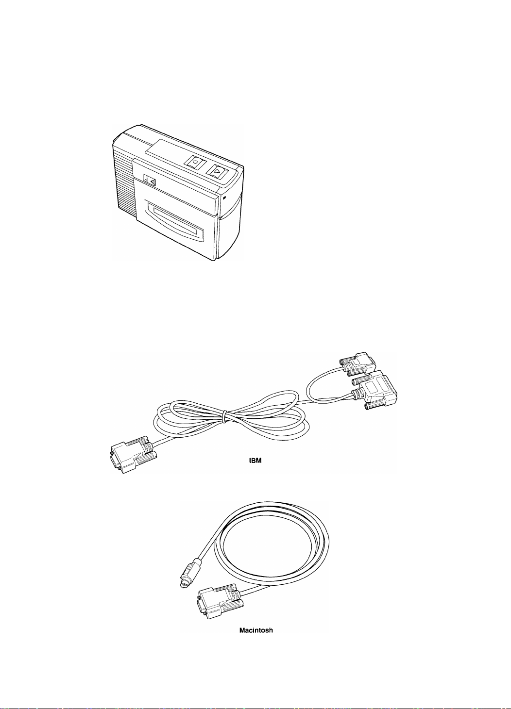
Unpacking
P-TOUCH PC Printer
Connection cables (for IBM and Macintosh compatible
computers)
Page 5
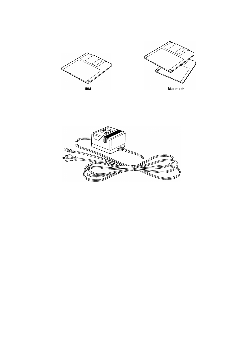
P-TOUCH PC Printer software
AC adaptor
This AC adaptor has been speciaMy designed for use with your P-TOUCH
PC Printer. Do not attempt to use it to power another electrical appliance,
and never try to power your P-TOUCH PC Printer with another AC adap
tor.
Guarantee
Please read this guarantee carefully and keep it in a safe place.
Tape catalog
The tape catalog gives you a list of the many different tapes that you can
use with your P-TOUCH PC Printer.
Order form
Use this order form to order new tapes.
Page 6

Laminated tape (one piece)
This tape is supplied so that you can start using your P-TOUCH PC Printer
immediately. Consult the tape catalog to order the specific kind of tape
that you may need.
Page 7

Precautions
I P-TOUCH PC Printer
• To avoid injuries^ do not touch the cutter's edges.
• Do not touch the printer head. The printer head becomes hot when
workings and remains hot for a while after the power has been
switched off.
• Do not place the printer too close to a source of electromagnetic
interference such as a television set.
• Keep the printer out of direct sunlight.
• Avoid using the printer in extremely dusty places.
• Use the AC adaptor designed exclusively for the P-TOUCH PC
Printer.
• Disconnect the AC adaptor from the wall outlet if you do not
intend to use the printer for a long time.
• Do not clean the printer with alcohol or other organic solvents.
Use only a soft, dry cloth.
• Do not leave any rubber or vinyl on the machine for an extended
period of time. Doing so may cause staining.
I
Tape
• Do not pull on the tape. This may damage the tape cassette.
• After cutting a lettering tape, immediately remove the cut portion
of the tape to avoid jamming the tape exit.
I
Floppy disks
• Never open the shutter or touch the magnetic material.
• Keep floppy disks away from magnets or other sources of magnetic
field.
• Never expose the disk to extremely high or low temperatures.
Page 8

Connecting the P-TOUCH PC Printer
Warning: Before you make any connection, be sure to switch off the
power to both the P-TOUCH PC Printer and the computer.
1. Connect the connection cable to the P-TOUCH PC Printer and to
the COM connector (IBM) or printer connector (Macintosh) of
your computer.
Note: (IBM only) The end of the cable with two connectors goes to the
computer side. Use the connector that is compatible with the COM port
of your computer, and leave the other connector unconnected.
2. Connect the AC adaptor to the P-TOUCH PC Printer and to an
AC outlet.
3. Switch the P-TOUCH PC Printer on.
4. Switch the computer on.
Note: To switch the system off, switch the computer off first, then the
P-TOUCH PC Printer and other peripherals.
Page 9

Tape cassettes
A laminated tape cassette is supplied with the P-TOUCH PC Printer for
temporary use.
Other tapes are available in a wide range of background colors, type col
ors, and tape sizes. We encourage you to use this variety of tapes for color
coding and other style-intensive uses.
With this in mind, we have designed the P-TOUCH PC Printer to allow
quick and easy insertion and changing of tape cassettes.
Inserting a tape cassette
Note: When you insert or remove a tape cassette, be sure to place the
P-TOUCH PC Printer on a flat, stable surface.
1. Flip the cassette compartment cover knob to release the cassette
compartment cover.
2. Lift the cover so you can easily reach the tape cassette.
Page 10

3. If there is a tape cassette already in the compartment, pull it
straight up to remove it.
4. Remove the stopper from a new tape cassette.
5. If the tape inside the cassette is loose, use your finger to wind it in
the direction of the arrow on the plastic tape cassette until it is
taut.
Page 11

6. Insert the tape cassette firmly into the cassette compartment.
7. Shut the cassette compartment cover. The cover knob will auto
matically lock.
8. Put the P-TOUCH PC Printer in its working position (as shown
below), and press power switch to turn the LED indicator on.
Note: The LED indicator is lit when the printer is powered and operation is normal. It flashes when an error is detected. See “Troubleshoot
ing” on page 11 for details.
9. Press the tape FEED/CUT button to remove any slack from the
tape.
Note: When you attempt solid black (or other color) printing, white
spots may appear in characters or graphics. This is caused by a printer
I protection function and is not a sign of malfunction.
Page 12

Label stick
The attached stick enables the label backing of the tape to be removed
easily. You can also use it to rub instant lettering tapes.
To remove the tape backing
1. Hold the tape in the left hand with the printed surface upside,
and the stick in the right hand.
2. Pass the tape halfway through the slot of the stick.
3. After turning the stick inward halfway, pull the stick to the right.
To transfer the label to paper
Instant lettering tapes act as rub-on character transfers. After creating a
label, simply position the characters over a sheet of paper. By rubbing the
instant lettering tape's non-printed side with the attached label stick, you
can transfer the tape's contents directly onto paper.
Note: Hold the paper very firmly and do not allow it to move while rub
bing the tape.
Page 13

Cleaning the print head and rollers
Occasionally, specks of dust or dirt may attach themselves to this
machine's print head or rollers. This is particularly likely when using the
unit outdoors, or in very dusty environment. When this occurs, the print
element obstructed by the dust cannot print, causing unprinted (blank) line
to stretch across the label. Vertical lines indicate dirty rollers; horizontal
lines indicate dirty print head.
Therefore, like a tape recorder, this machine's head and rollers may need
to be cleaned from time to time.
How to clean the print head and rollers
1. Turn off the machine.
2.
Open the cassette compartment cover and remove the tape cas
sette. The print head and rollers are located in the cassette com
partment.
3.
Print head: Wipe the print head gently with a dry cotton swab in
the up-down direction.
Rollers: Wipe each roller vertically with a dry cotton swab while
rotating the roller with your finger.
4.
Again try a practice print. If dust still remains^ dip the cotton
swab in isopropyl (rubbing) alcohol and repeat step 3.
5.
If none of the above works, contact your service representative.
Warning: Do not touch the printer head with your finger. The printer
head becomes hot when working, and remains hot for a while after the
power has been switched off.
10
Page 14

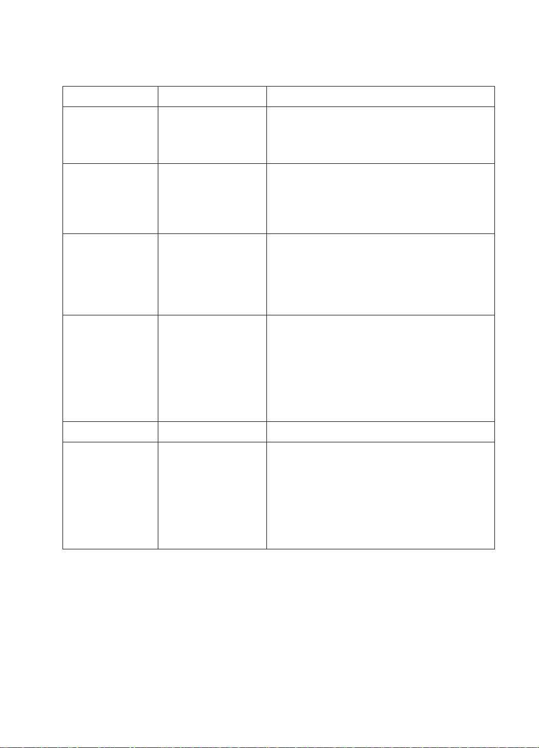
Troubleshooting
Problem
The printer does not print.
Zebra tape appears.
The LED indicator is not lit.
The LED indicator flashes.
Possible causes Remedy
The adaptor cable is
not firmly connected.
The tape cassette is not
properly inserted.
The cassette compart
ment cover is open.
Tape end Install a new tape cas
The adaptor cable is
not firmly connected.
• Cutter error
Connect the adaptor
cable firmly.
Insert the tape cassette
properly.
Close the cover.
sette, then press the
Feed/Cut button or
switch the printer off
and on again.
Connect the cable
firmly.
If this does not solve
the problem, contact
your dealer.
Remove any jammed
tape or adhesive from
the cutter.
Press the Feed/Cut but
ton or turn the printer
off and on again.
Lines appear on the printout
11
No tape cassette
The tape cassette was
replaced during data
transmission
Tape end
The print head and/or
the rollers are dirty.
Install a new tape cas
sette, then press the
Feed/Cut button or
switch the printer off
and on again.
Press the Feed/Cut but
ton or turn the printer
off and on again.
Install a new tape cas
sette, then press the
Feed/Cut button or
switch the printer off
and on again.
Clean the print head
and/or the rollers.
Page 15

Specifications
Hardware
Main
unit
Interface
Tape cassette
Sensors
Power-on checks
When the power is turned on and the system initialized, if an error is detected, the LED is
turned off, DTR is set to BUSY (no Xoff) and the power remains on.
External error detection
When an error caused by noise or other external factors is detected, the power is turned
off.
Operation
Printer
Power source
Dimensions
Weight
Display: LED (Power/Error)
Switches: Power switch
Feed and cut switch
Printing system: Thermal copy laminating / thermal transfer
Print head: 180 dpi, 128 dots
Printing height: 18 mm
Print speed: 30 mm/s
AC Adaptor 9V 2A
82(W)x226(D)x167(H) mm
approximately 1.300 kg
RS232C or equivalent (9-pin)
Type: Laminating 6, 9, 12, 18, 24 mm
Non-laminating (thermal film tape) 24 mm
Lettering 12 mm
Tape length: 15 m
Tape: Tape end sensor (photo sensor)
Cutter: Cut position sensor (leaf switch)
Cassette: Cassette sensors (x4) (mechanical sensors)
12
Page 16

Software
Printing
Buffer
Transmission
control
Commands
Print type:
Print condition:
Bit image only
Auto tape cut: ON / OFF
Left and right margins: small, medium, large, none
*Print buffer (normal):
**Reception buffer;
Baud rate;
Approximately 30KB (27 cm)
512B
9600 (fixed); data reception at 9600 bps
Busy output: Xon/off and DTR
Length:
Parity:
CR
LF
FF
CTRL-Z
ETX
ESC J
8 bits (fixed)
none (fixed)
Carriage return
Line feed
Print command
Print command with feed
Same as CTRL-Z
Line feed
ESC$ Absolute position assignment
ESC\
ESC*
ESC@
**
Relative position assignment
Bit image selection
Initialization
ESCiS Status request
ESCiM
ESCiD
Mode specification
Print density control
ESCiP Printing command for continuous page
Others
Tape cut ON / OFF
Tape end detection
Cutter error detection
Tape type / Tape detection (with or without)
*Print buffer: stores the print image that is printed by the thermal head
**Reception buffer: stores a received interface data temporarily until it is sent to the print
buffer
13
Page 17

Interface connector
Q
Type
Pins
0
D-SUB9 PIN
© CD carrier detection
© RXD reception data
© TXD transmission data
© DTR data terminal ready
© GND signal earth
® DSR data set ready
© RTS transmission request
® CTS transmission enabled
0
(input) ignored
(input)
(output)
(output)
(input) ignored
(output) always on
(input) ignored
® Not connected
Items marked "ignored" are irrelevant and can be connected or left disconnected.
14
Page 18

Transmission controls
Busy
Busy output
ON if one of the following is ON:
1. Buffer busy
ON if the remaining data area in the reception buffer is 256 bytes or less;
OFF if the remaining space in the reception buffer is 384 bytes or more.
2. Printer busy
ON during printing; OFF when not printing.
1. Entering busy condition:
Outputs a Xoff (13h) and requests to stop data transmission.
Turns off DTR and requests to stop data transmission.
2. Exiting busy condition:
Outputs a Xon (11 h) and allows data transmission.
Turns on DTR and allows data transmission.
Commands
Name Function
CR Carriage return
LF
FF Printing command
Line feed
code
OD
OA
OC
Hex
Moves to the beginning of the same line.
Feeds line by 24 dots; does not move when the print
buffer is empty; does not move to the beginning of
line.
Print the buffer data without ejecting; when the cut
mode is set to ON, the tape is cut when the cutting
position is reached; invalid when the print buffer is
empty.
Description
CTRL-Z Printing command
with feed
ETX
15
Printing command
with feed
1A
03 Same as CTRL-Z.
Print the buffer data and ejects; when the cut mode
is set to ON, the tape is cut after printing; when the
print buffer is empty, feeds the tape and cuts it off.
Page 19
Escape sequences
Sequence
ESC+J+n
ESC+$+n1 +n2 Absolute position
ESC+\+n1 +n2 Relative position Moves by n1-i-256xn2=N dots from the current
ESC+*+m+n1+n2
+data bytes
Line feed
Selects bit image
printing
Function Description
Feeds line by 24 dots; invalid when the print
buffer is empty; does not move to the beginning
of line.
Any value can be used for n.
Moves by n1+256xn2=N dots (1/60 inch) from
the beginning of the line.
0<n1<255; 0<n2<2
The target position must be inside the page or
else an error is detected.
position. N is a signed integer. For a negative
number (-N), use 65536-N
0<n1<255; 0<n2<255
The target position must be inside the page or
else an error is detected.
Prints the bit image data “data byte”.
m=39 is the only valid value. Other values result
in the command being ignored.
n1=total number of dots modulus 256.
n2=total number of dots/256 (integer).
(n1-h256xn2)x3 image bytes are required.
Detects a print buffer error if the image extends
beyond the page limits.
ESC+@
ESC+i+D+byte
Initialization
Print density and bar
code controls
Clears all data in the print buffer.
bit 0 ~3: Print density control (default=3)
0: no change
1 ~5: five levels (other values invalid)
bit 4 and 5: Barcode control (default=3)
0: no change
1: no barcode
2: barcode only
3: including barcode
16
Page 20

Sequence
Function
Description
ESC+i+M+byte
ESC+i+P
ESC+\+S
Mode setting
Print command for
continuous pages
Status information
request
bit 0 ~ 4: Feed amount (default=large)
0 ~ 7 none
8 ~11 small
12-25 medium
26 ~ 31 large
bit 6: Auto cut (default=ON)
OOFF
1 ON
bit 7: Mirror print (default=OFF)
OOFF
1 ON
This command should be set before sending
data.
Mirror printing is not possible with non-laminated
(thermal film) tapes.
Feed amount is automatically set to large with
lettering tapes.
Images longer than 27 cm can be printed contin
uously on connected pages; invalid when the
print buffer is empty; prints even if the only data
in the print buffer are spaces.
I -8 header: 80h, 20h, 42h, 30h, 30h, 30h,
OOh,OOh
9 error code
bitO: no tape
biti: tape end
bit2: cutter jam
10 error code
bitO: tape change error
biti: print buffer full
bit2: transmission error
bit3 reception buffer full
II tape width (1 ~127mm)
0: no tape
12 tape type (0-127)
0: unidentified tape
1: laminated tape
2; lettering (iron copy)
3: Non-laminated (thermal film) tape
13-15 OOh (fixed)
16 mode (same as for “Mode setting”)
17 print density (same as for “Print density
and barcode controls”)
18-32 irrelevant
17
Page 21

Tape width and print area
The following illustration shows the relationship between the tape width and the print
area.
12mm
2mm
___1_______
2mm
9mm
1mm
1mm
6mm
1mm
3mm
3mm
24mm
18mm
10.5mm
Top Margin
Bottom Margin
Right Margin
Tape
Width
Left Margin
3mm
Page Length
The page maximum length is 1 m regardless of the tape width.
Left and right margins are as follows:
None
29 dots
Small
56 dots
Medium Large
86 dots
185 dots
Upper and lower margins are fixed. The following table shows the total height of the print
area for different tapes.
Tape width
Print area
(mm) (mm/dots)
24 18.0/128
Upper and lower margins
(mm)
3
Dot positions
U128
Printable lines
(1 llne=24 dots)
5 lines + 8 dots
18
t C. o.u/0/
9 6.9/49
6
12.0/85
3.9/28
3
o 0/1
c.
1 6M09
1
U85
UU 1
6U88
3 lines + 13 dots
L. Ill ICO T yj uu io
2 lines + 1 dot
1 line + 4 dots
18
Page 22

brother»
UB7438001(B)
Printed in Japan
 Loading...