

Page 1
INST
.RUCTION
FOR
MANUAL
BROTHER
LH4-B814-2,
-3, -5
BROTHER
NAGOYA,
INDUSTRIES,
JAPAN
LTD.
Page 2
~
FEATURES
~
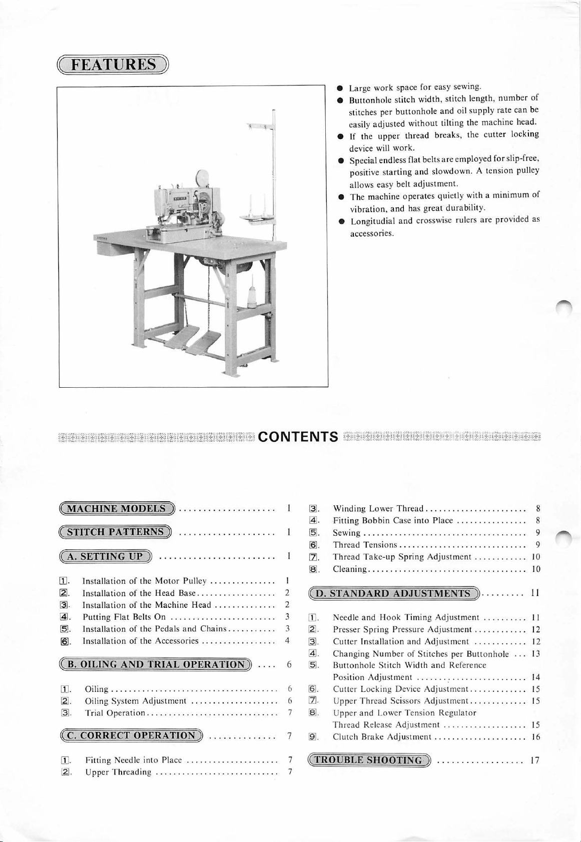
• Large
e
Buttonhole
s
titches per
easily
e If the
device will
•
Special
positive s
allows
e
The
vi
bration,
e
Longitudial
accessories.
work
adjusted
upper
work.
endless flat
tarting
easy
machine
and has
space
for
stitch
width, stitch
butt
onho
without
thread
belts
and
belt
adjus
opera
tes
great
and
crosswise rulers
easy
sewing.
length,
numb
er
of
le
and
oil s
upply rate can
tilting
the
machine
break
s,
the
cutter
are
employed
slowdown. A tension pulley
tment.
quietly
durability.
with a
are
for
minimum
provided
be
head
loc
king
slip-free,
of
as
.
~
MACHINE
~
STITCH PA:rTERNS » ............
« A. SETTING
[I]. In
~-
!3].
@.
~-
[2]
~ B
[1].
~C.
[I].
st
In
sta
I
nstallation
Putting
In
stallation
. Ins
.
OILING
Oiling . . . . . . . . . . . . . . . . . . . . . . . . . . . . . . . . . . . . . . 6
~-
Oiling
~-
Trial
CORRECT
Fitting
[2]
.
Upper
MODELS ~ ...............
UP
» .......................
allation
tallation
of the
Motor
llation
of the
Head
of
the
Mach
Flat
Belts
On
of the
Pedals
of
the Accessories . . . . . . . . . . . . . . . . . 4
AND
TRIAL
System
Operation................
Adjustment
OPERATION
eedle
int o Pla
Threading
. . . . . . . . . . . . . . . . . . . . . . . . . . . . 7
Pulley . . . . . . . . . . . . . . . I
Base................
ine
Head
. . . . . . . . . . . . . . 2
. . . . . . . . . . . . . . . . . . . . . . . . 3
and Chains...
OPERATION
. . . . . . . . . . . . . . . . . . . . 6
.
.......
~
. . . . . . . . . . . . . . 7
ce
. . . . . . . . . . . . . . . . . . . . . 7
...
. .
......
. .
.
..
. . . . . . . . 3
~
..
. . 6
......
~-
~-
~-
!21.
rll.
~-
2
~
D.
STANDARD
[1]
.
~-
~
-
~-
~-
!21.
[ZI.
7
~-
~-
~
TROUBLE
Winding Lower
Fitting
Bobbin
Sewing... ..
Thr
ead Tensions.
Thread
Cleaning.
Case
.....................
Take-up
. . . . . . . . . . . . . . . . . . . . . . . . . . . . . . . . . . . I 0
ADJUSTME
eed
le
and
Hook
Pre
sser
Spring Pressure
Cutter Installat
Ch
anging
Buttonhole Stitch
Positi
on
C
utt
er Locki
Upper
Thread Scissors
Upper
and
Thr
ead
Clut ch Br
ion
Number
Adjustment
ng Device
Lower Tens
Release
ake
Adjust
SHOOT
Thr
ead..
..........
into Place
. . . . . . . . . . . . . . . . . . . . . . . . . . . . 9
Spring Adjustment
.
..........
. . . . . . . . . . . . . . . . 8
...........
. . . . . . . . . . . . I 0
NTS] .........
Timing
Width
Adjustment
ING
Adjus
tment
..........
Adjustment
and
Adjustme
of
Stitches
and
. . . . . . . . . . . . . . . . . . . . . . . . . 14
Adjustment........
Adjustment.
ion Regu
...................
ment
...............
~
. . . . . . . . . . . . . . . . . . 17
.........
nt . . . . . . . . . . . . 12
per Buttonhole
Reference
..... 15
. . . . . . . . . . . .
lator
......
. . .
. . .
8
9
II
II
12
13
15
15
16
Page 3
~
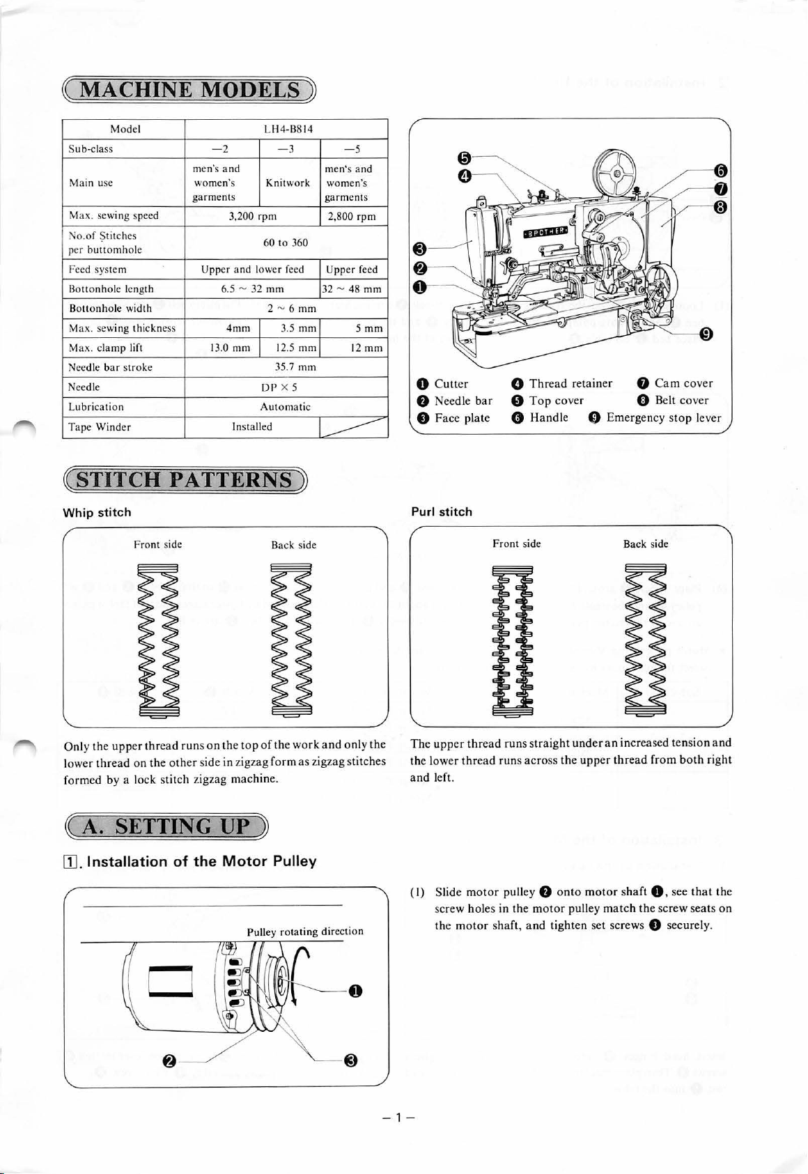
MACHINE
Model LH4-B814
Su
b-class - 2
Main usc
Ma
x. sewing speed
N
o.of
~titches
p
er
buttomhole
Feed system Upper
Botto nhole length 6.5 - 32
Bot
tonhole
wid
th
Max. sewing thic
Max.
clamp lift
Needle
bar str
Needle
Lubr
icati
Tape
Win
kness
oke
on
der
MODELS
men's
and
women's
gar
ments
3.200 rpm 2,800 rpm
and
4mm
13.0
mm
Installed
-3
Kn
itwork
60 to 360
lower feed
mm
2-6
3.5
12.5
35.7
DP
X 5
Automatic
~
- 5
men's and
women's
garments
Upper
32-48
mm
mm
mm
mm
5mm
12
-----
feed
mm
mm
0 C
utter
f)
Needle
bar
8 Face plate
0
0 T
0
Thread
retain
er
op
cover 0 Belt
Handle
f)
Emergency s
8 Ca m cover
cover
top
lever
( STITCH
Whip
stitch
Fro
nt side
Only the
lower thread on the ot
formed
~
[]]
upp
er
thr
ead runs on the
by
a lock stitch zigzag machine.
A.
SETTING UP
. Installation
PATTERNS
top
her
side in zigzag form
Back side
of
the work
~
and only
as
zigzag stitches
~
of
the
Motor
Pulley
the
Purl stitch
The
upper
the l
ower
and left.
Fron
t side B
thread
runs
thre
ad runs across the
straight
under
upper
an
increased
thread
ack side
fro m
ten
sion and
both
right
(
I)
Slide
motor pull
screw holes in the
the
motor shaf
- 1-
t,
ey
motor
and
f)
onto
motor sh
pulley
tig
ht
en set screws e sec
matc
aft
0,
h the scr
see that
ew
seats on
ur
ely.
the
Page 4
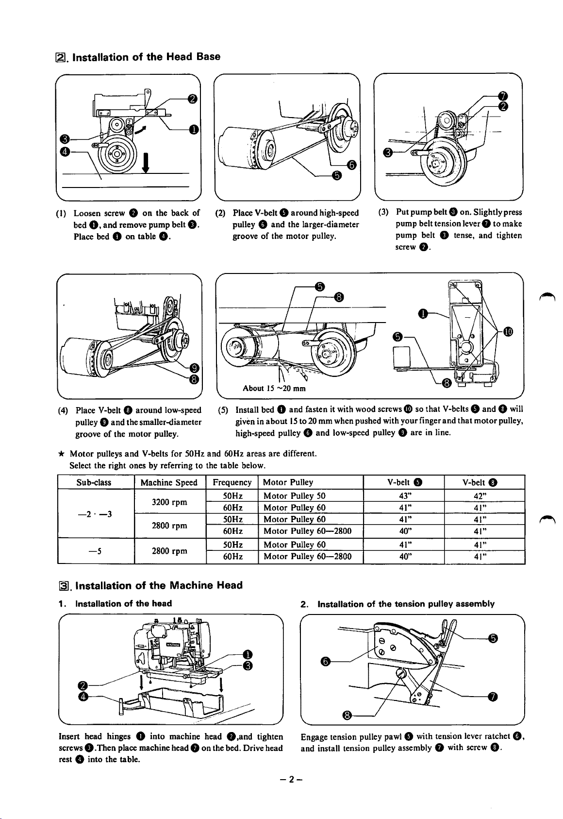
121.
Installation
(I) Loosen screw 8
0.
bed
Place bed 0 on table
and remove pump belt
of
the
on
Head Base
the back of
8.
8.
(2)
Place V-belt 8 around high-speed
8 and the larger-diameter
pulley
of
groove
the motor pulley.
(3)
Put pump belt 8 on. Slightly press
pump belt tension lever
pump belt
screw
8 tense, and tighten
8.
0 to make
About
15
-20
mm
(4)
Place V-belt 0 around low-speed
pulley
0 and the smaller-diameter
groove of the motor pulley.
(5) Install bed
given in about
high-speed pulley 8 and low-speed pulley 0 are
0 and fasten
15
to
20
* Motor pulleys and V-belts for 50Hz and 60Hz areas are different.
Select the right ones by referring to the table below.
Motor
Sub-class Machine Speed
3200 rpm
-2·-3
2800
rpm
2800
the
head
rpm
Machine
-5
~.Installation
1.
Installation
of
of
the
Frequency
50Hz Motor Pulley
60Hz
50Hz
60Hz
50Hz
60Hz
Head
Pulley
Motor Pulley 60
Motor Pulley
Motor Pulley
Motor Pulley
Motor Pulley
2.
it
with wood screws
mm when pushed with your finger and that motor pulley,
50
60
60-2800
60
60-2800
Installation
of
V-belt 8
the
tension
fli)
so that V-belts 8 and 0
in
line.
V-belt 0
43"
41"
41"
40"
41"
40"
pulley
assembly
will
42"
41"
41"
41"
41"
41"
Insert head hinges 0 into machine head 8 ,and tighten
screws
8.
Then place machine head 8 on the bed. Drive head
8 into the table.
rest
Engage tension pulley
and install tension pulley assembly 0 with screw
-2-
pawl8
with tension lever ratchet
0.
0.
Page 5
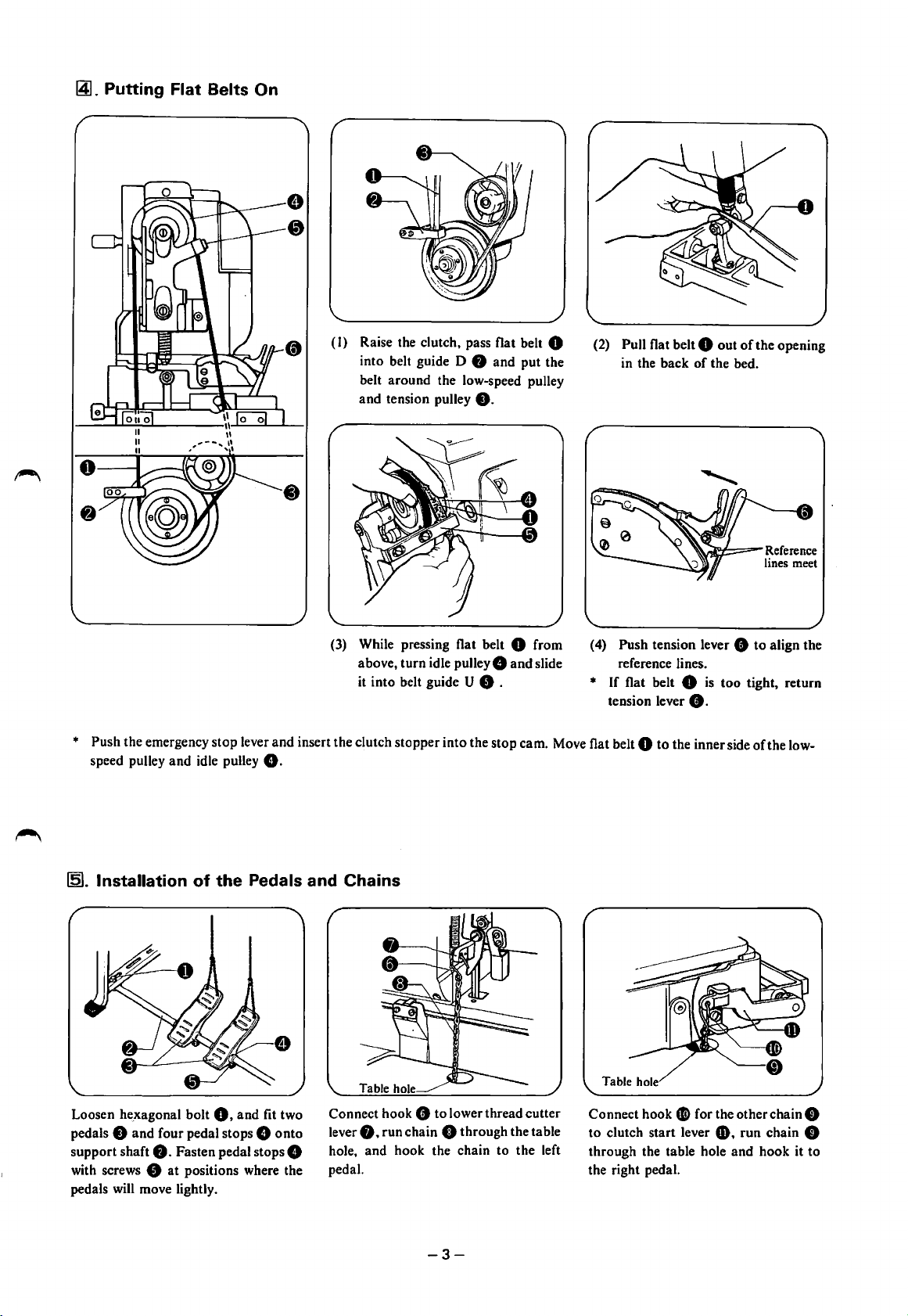
~.
Putting Flat Belts On
(I)
Raise the clutch, pass flat belt 0
into belt guide D 8 and put the
belt around the low-speed pulley
and tension pulley
8.
(2)
Pull flat belt 0 out
in the back of the bed.
of
the opening
~~=~Reference
(3)
While pressing flat belt 0 from
above, turn idle
it into belt guide
pulley&
and slide
U 8 .
(
4)
Push tension lever 8 to align the
reference lines.
* If flat belt 0
tension lever
is
too tight, return
8.
* Push the emergency stop lever and insert the clutch stopper into the stop cam. Move flat belt 0 to the inner side
speed pulley and idle pulley
151.
Installation
of
the Pedals and Chains
8.
lines meet
of
the low-
Loosen
pedals
support shaft
with screws 8 at positions where the
pedals will move lightly.
he_xagonal
bolt
0.
and fit two
8 and four pedal stops 8 onto
8.
Fasten pedal stops 8
Connect hook
0.
lever
hole, and hook the chain to the left
pedal.
8 to lower thread cutter
run chain 8 through the table
-3-
Connect hook
to clutch start lever
through the table hole and hook it to
the right pedal.
Gi>
for the other chain 8
G).
run chain 0
Page 6
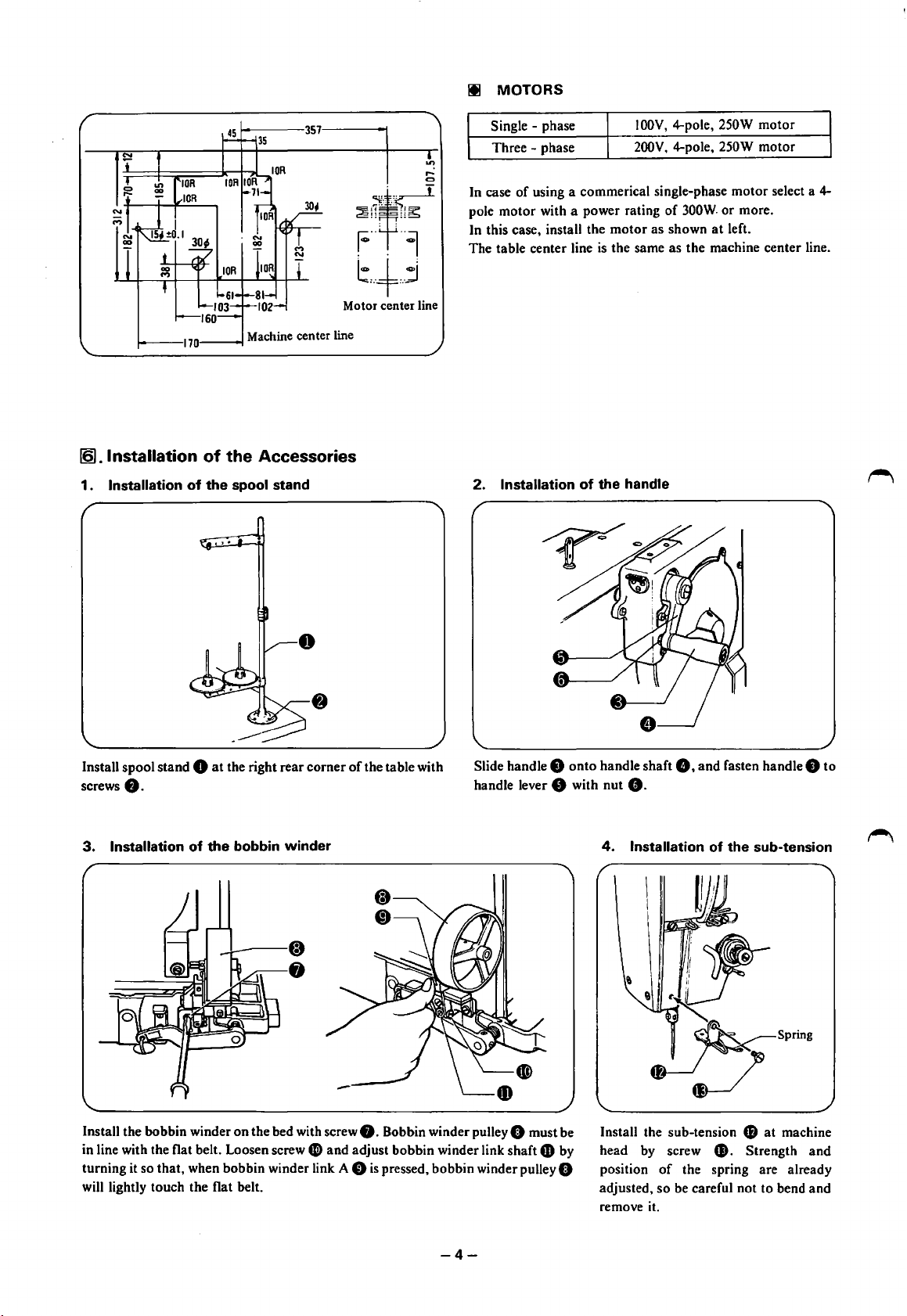
12)
.Installation
of
the
Accessories
Ill MOTORS
Single - phase
Three-
~
,...
C)
In case
pole motor with a power rating
~i~~
In this case, install the motor as shown
The table center line
phase
of
using a commerical single-phase motor select a 4-
is
the same as the machine center line.
t,+j
Motor center line
IOOV,
4-pole, 250W motor
200V,
4-pole, 250W motor
of
300W.
or more.
at
left.
1 . Installation
Install spool stand 0
screws
0.
3.
Installation
of
of
the
spool stand
at
the right rear corner
the
bobbin
winder
of
the table with
2. Installation
Slide handle 8 onto handle shaft
handle lever
of
the
8 with nut
4.
handle
8.
Installation
8.
and fasten handle 8 to
of
the
sub-tension
Install the bobbin winder on the bed with screw
in line with the flat belt. Loosen screw
turning it so that, when bobbin winder link A
will lightly touch the flat belt.
0 and adjust bobbin winder link shaft 0 by
0.
Bobbin winder pulley 0 must be
0
is
pressed, bobbin winder pulley 0
-4-
fB
at
Install the sub-tension
head
by
screw
position
adjusted, so be careful not to bend and
remove it.
of
$.
the spring are already
machine
Strength and
Page 7

5.
Installation
of
the
crosswise
ruler
and
longitudinal
ruler
(I) Fasten crosswise ruler • to length
(2)
Fasten longitudinal ruler 8 to bed cover
* In case of sub-class
6.
Installation
When elastic materials such
be
material to
sewn altogether.
of
-5,
fix ruler directly on the bed.
the
tape
winder
as
knitted materials
·----
•
(I) Install tape winder
e.
fl
on top cam cover
feed
and
plate
41
with bolts
41)
with
bolts.
tape
guide
(in case
is
used, a strong buttonhole can
I)
with screws
and washers
(2)
(3)
CD
and washers
41.
fD.
of
sub-class
Fasten tape guide rear
length feed plate
Fasten tape guard front 8 in case
fasten tape guard front
screws G).
-2
and
-3)
be
made with a tape at the backside
fa
41
by screws
fJ) in case
and tape guide front
•.
of
sub-class
of
sub-class
of
-2
-3
the
fD
to
and
by
7.
Installation
(4) Pass a tape through as per the picture at the above.
Fasten belt cover G to the back
G and screws G).
hinge
-5-
of
the
belt
cover
of
the bed with belt cover
Page 8

~B.
(]].Oiling
(I)
(2) Connect vinyl tube joint (black) 0 with joint nut (black)
OILING
Remove belt
AND
and
tilt the machine.
TRIAL
OiPE.R~Aflt(Q)~-~
f).
(3) Connect vinyl tube joint (white) 8 with
joint
nut (white)
••
© Oiling
'-------·
(4)
Gently pour oil into oil tank 0 under the table through
filter 8 until the tank
••
If oil level falls below reference line 8 .
is
filled up to upper reference line
* Remove the face plate, side cover and belt cover, and oil all working parts.
* Pour a drop
~.
Oiling
or
two of oil to the arrow-indicated points daily. *Note: Use white spindle oil.
System
Adjustment
8-~~=
======~~~=====
_/
Base
A
few
minutes after the power
of
the base by turning it until oil level can be seen in gauge pipe
• Oil level falls during sewing.
is
switched on, adjust oil flow regulator 8
~Moreoil
Less oil
on
the right
0.
-6-
©
Hook
oil
flow
adjustment
Adjust oil flow to the hook by turning
oil regulator shaft 8 on the front
bed.
of
the
Page 9

~.Trial
Operation
At stop
(I)
Before star
clut
(2)
Switch
(3) The ma
~
C.
CORR
ting
ch stopper
the ma
chine will s
the
f)
is in stop c
chine
on.
tart
ECT
machine,
whe n the rig
be
am
OPERATION
!]] . Fitting Needle into Place
I
sure
to confirm
asse mbly O.
ht
peda l is stepped
that
on.
~
(4) Release the peda l
pedal
is kept
stepped
(5)
After
a fixed
num
sto
ps.
When
(6)
Repeat
DP
Use a
Lo
ose
n set screw
facing in
th
your
e needl e hole.
the left p
X 5 needle
abov
dire
e s
edal
tep
f)
ctio
At s
tart
once
the machine s
on,
the mac
ber
of s
titch
es
is
stepped
s (3), (4)
and
on,
(5) a few
0.
.
ho
ld the needle with its
n. a nd insert
the
tarts runnin
hine will n
are
made, the
the work
nee
dle
all the way
clamp
tim
groo
g. (If
ot
sto p.)
machine
es.
ved si
rise
the
s.
de
into
[21
.
Upper
Threading
I I
*When
threading
other side to this side
the needle. pass from the
Pass a
Thr
thread
Pass a
and
ead han
onl
<
Synthetic fith
thread
sprin
g.
<
Co
tton thr
ger
y
throug
~
thread han
th rough thread
er
ead
thread
I I
'
'
hang
ger
>
>
er
Spr
ing
.
- 7-
Page 10

~-
Winding
Lower
Thread
(I)
Check the power switch that it
(2)
Slide bobbin 0 onto bobbin winder spindle
(3)
Pass the thread in the order
wind a
few
turns
of
the thread around bobbin 0 in the
arrow direction.
(4) Push bobbin winder link A
will wind on the bobbin.
(5)
After the bobbin finishes winding the thread, bobbin
winder link A
(6)
Remove the bobbin 0 and cut the thread with the thread
cutter
*
Turn
screw 0 to adjust the bobbin to the correct thread
winding volume.
8 automatic return to its original position.
8.
is
on.
of
the numbers shown, and
8 and release it. The thread
f).
• If the thread winds unevenly on the bobbin
screw
G. and move bobbin winder tension guide
left
or
right as necessary.
right
Uneven with
more thread
wound on left
bobbin
case
Uneven with
more thread
wound
on
© Threading
After winding the thread on the bobbin, pass the thread in the order shown below.
0,
f)
loosen
to the
~-
Insert the bobbin into the bobbin case.
~.
~itting
Bobbin
Case
into
Pass the thread through a slit in the
bobbin case and under the tension
spring.
Place
Hold the bobbin case by latch
Let
the thread end fall in front
-8-
Pass the thread through another slit
and pull it out of the thread hole.
0.
and insert it into the hook.
of
the bobbin case.
Page 11

~-Sewing
©
How
to
use
the
emergency
stop
lever
-8
(I) Make sure that the clutch stopper
then switch the power on.
(2)
Depress the left pedal to raise work clamp
work under it, and release the left pedal.
(3)
Depress the right pedal to start the machine.
When the machine starts running,
(4)
The machine
stop.
(5)
Depress the left pedal and take out the work.
©
How
to
use
will
sew a fixed number
the
cutter
locking
device
is
in
the stop cam, and
0,
place your
release the right pedal.
of
stitches and then
Push emergency stop lever 8 down and immediately release
it. The machine will stop.
©
How
to
use
the
handle
Keep cutter lock lever 8 lightly depressed with your finger
until the machine stops. The cutter
Turn handle 8 after confirming that the needle is not in the
work.
will
I§). Thread Tension
* Thread tensions vary with sewing conditions. Refer to the following when selecting suitable tensions.
1.
Lower
thread
tension
ttfoake
Spring
Turn adjusting screw 0 to such an extent that you will
little resistance when pulling the thread out
Standard
tensions
not drop.
ofthe
feel
bobbin case.
a
~
0
Brake spring
s
-2
-3
-5
in
the bobbin case reduces bobbin racing.
-9-
About.
About.
About.
Purl
15
15
15
"'
"'
"'
20g
20g
20g
Whip
About. 30g
About. 30g
About. 30g
Page 12

2.
Upper
Whip stitch
thread
___
tension
~
(~}
Purl
stitch
--r--~
(B)
Upper
~--1--~
~---1~(~)
(A):
Bar
tacking
(B): Zigzag stitches
IZ]. Thread
(1) Thread
Take-up
take-up
Spring
spring
height
ment
Turn tension regulator nut 8 to adjust
thread tension for
Adjustment
tension
regulator
bar
tacking (A).
(2) Thread
adjust-
Less tension
Lower
ment
Turn
thread tension for zigzag stitches
(Decrease tension for whip stitches; and
Increase tension for purl stitches.)
take-up
tension
tension regulator nut 0 to adjust
spring
tension
regulator
About
20
Less tension
adjust-
"'
30g
(B).
Adjust the working scope
loosening set screw
regulator .itself. (Standard range
IBI.
Cleaning
Remove lint and dust from thread
passages.
of
thread take-up spring 0 by
0 and turning the upper thread tension
is
about 8 mm)
Adjust the thread take-up spring tension
0.
stud
Remove lint and dust from around the
work clamp.
(Standar~
by
turning tension
ten~ion
is
about 20 to 30g.)
Remove the bobbin case, and remove
lint and dust from around the shuttle.
And wipe the bobbin to remove oil.
-10-
Page 13

(
D.
STANDARD
[].
Needle and
*
The
correct
from
*
When
s
ure
that the needle
1.
Needle
timing
the lowest
adjusting
bar
Hook
position
the n
upward stroke
Timing
of
the needle
eedle
bar upward stroke,
is
at
the
ADJUSTMENTS
~
Adjustment
and
the
hook
center
of
the n
is necessary
needle
eed
le hole plate.
bar
for
the
height
hook
point to
and the clea
scoop an
ran
ce
upper
between
the
thre
needle
ad
loop
and
as
hook
the needle rises
point
make
Loosen screws 0
Mo
de l 8814-2 · -5)
2.
Needle bar
Loosen
screw 0 an
top
end
of
the needle eye when
and
height
d raise
turn
or
shuttle 0
3.5
mm
or lower
hook
I
I I
I I
I I
\.1
,,
unti
(for
-----
needle
point
l h
ook
Model
0
bar
f)
0
point
8814- 3)
f)
until there
meet
f)
the
meets
from
is a
center
the
center
the
lowest position.
clearance
line
of
needle
c
line
of
the needle wh
of a
bout
1.5
to
0.
en need
*N
eve r loosen scr
2
mm
between
e
~
0
le 0
ri
ews
the hook
ses
0 in
by
2.5
mm
any case
point and
(fo r
.
the
3.
Clearance between
Loosen
screws
0 and move h
h
ook
point
f).
4.
Clear
ance
Ab
out 1.0
between
-l.Sm
needle
ook 0 forward
bobbin
m
and
case
hook
holder
point
or
back
and
until
ther
bobbin
e is a cle
arance
case
holder
Loosen scr
case hold
to 1.5 mm.
Mak
e sure that hook
bracke
of
about
0.
03
bracket
ews
f0
and
adj
er 0 and bobbin case h
4D
t e wh
en
it
rotat
es.
to
0.08
ust the
will
mm
older
not
clear
touch
betwecnneed
ance between
bracke
t e to
bobbin
le 0
and
bobbin
abou
t 1.0
case holder
-
11
-
Page 14

12).
1.
Presser
Presser
Spring
spring
Pressure
adjustment
Adjustment
2.
Work
clamp
tilt
adjustment
About
77
mm
Compress presser spring
bottom
8
and retighten screw
131.
of
washer 0 and the top
to
about
77
mm with presser
Cutter
Installation
0.
8.
adjust the distance between the
of
presser bar guide bracket
bar
guide bracket set screw
and
Adjustment
---cl--
Fabric
Loosen screw 8 , and turn work clamp support spring shaft
8 until the bottom of work clamp 8
the work.
0,
Top
of
needle plate
f Parallel
is
parallel to the top
___
)
of
About
0.2
mm
-~n--
(I)
Temporarily fasten cutter 0
8.
screw
(2)
Turn the machine pulley by hand until the needle
nearly
at
the lowest position.
(3)
Loosen screw
back until the clearance between cutter 0 and the needle
bar
is
(6)
Keep cutter lock
the machine pulley with the other hand until cutter
falls to the lowest position.
0.
and move cutter
approximately 0.2 mm.
arm
8 pulled with one hand, and turn
to
cutter holder 8 with
holder8
bar
forward
(4)
Turn the machine pulley by hand until the needle
comes up to nearly the highest position.
is
(5)
Turn the handle until stop cam piece 8 8 rides on the
center of stop cam piece
or
8.
.,.--.--0
~--·
Top
of
needle plate
About 2
(7)
Loosen screw 8 and make an adjustment so that the
0
blade edge
needle plate.
(8) Turn the machine pulley by hand until the clutch
automatically engages.
mm
will
enter about 2 mm deep from the top
of
bar
the
-12-
Page 15

© Feed
adjustment
B
Loosen adjusting nut G and move pointer 0 to the line
directly under the same number as the cutter number
~-
Changing
The number
Any of the numbers
1 . Change
(Example:
L STITCH R L STITCH R
54
52
51
50
48
46
44
42
40
(I) See the above table for
(2)
Loosen thumb screw 0 and raise gear case cover
(3)
Fit change gear
(4)
Fit change gear 42 onto shaft R
(5)
After replacing the gears, be sure to close gear case cover
Number
of
stiches varies with buttonhole size. Select a suitable number.
of
gear
replacement
Selecting
360
319
300
283
252
226
203
182
164
34
of
Stitches
stitches shown in the below table (gear case cover) can be selected by change gear combinations.
119
stitches)
22
38
24
36
34
25
32
26
28
30
28
30
26
32
24
34
22
36
119
stitches, and look
onto shaft L.
147
133
119
107
96
86
77
68
60
in
such away that it will engage the other gear.
A.
per
Buttonhole
at
the
38
40
42
44
46
48
50
52
54
8.
Loosen adjusting nut
under the same number as the cutter number
Land
R columns.
G)
and move token
8.
CD
to the line directly
B.
2.
Stop
cam
replacement
(in case
Stop cam segment
Stop cam segment
of
sub-class
-2
AL
AS
and
-3)
(1) Remove the cam cover.
(2)
Turn the handle until stop cam piece 8 comes to a point
where it can
(3)
Loosen screws 8 and replace stop cam piece
If
the number
If it
is
107
of
stitches
stitches
-13-
be
easily taken off.
is
96
or less, use stop cam piece AL.
or
more, use stop cam piece AS.
8.
Page 16

~.
Buttonhole
1 .
Buttonhole
WI
Reference line A Reference line B
The
machine swings the needle to the left from the right
reference position in sewing forward
2.
Reference
Stitch
stitch
position
Width
width
adjustment
adjustment
and Reference
W2
and
back.
Backward
1
Position
Adjustment
Adjust after raising the small cover
Turning WI adjusting screw
clockwise increases the needle swing motion and turning it
counter-clockwise decrease it.
0.
f)
or
W2 adjusting screw 8
Reference line A
Adjust reference line A by loosening
Reference line B
Adjust reference line 8
adjustment
adjustment
by
e--
nut
0 with a box wrench
loosening nut G with box wrench and turning screw 8 in a similar way.
and
......
turning screw
0.
© Follow the under mentioned procedure when changing the stitch width and stitch reference pasition.
Left
zigzag
stitches
t !
Forward Backward
Wl
Reference line A
(
1)
Adjust reference line A so
stitches will not be cut by a falling
cutter.
(2) Adjust zigzag stitch width WI with
adjusting screw
f).
Wl
that
the
Reference line B
(3) Adjust reference line B so
right zigzag stitches will not be cut
by a falling cutter.
Right
stitches
zigzag
that
the
W2
(4)
Adjust
bar
tacking width
adjusting screw
width varies with manual turning
and high-speed operation due to
different thread tensions. Adjust it
by actually sewing.
Bar
tacking
8.
Bar tacking
W2
with
* The needle swing width
or
if a reference line
sewing forward
After turning the machine pulley by hand, be sure
cam. Then you may start the machine.
or
is
adjustable in excess
is
moved,
turn
back.
of
the work clamp width. If bar tacking width
the machine pulley by hand and make sure
to
use the emergency stop lever
-14-
that
is
adjusted to more
the needle will not touch the work clamp in
to
insert the clutch stopper into the
than
4 mm,
stop
Page 17

1§1.
Cutter
locking
Device
-
Adjustment
About 7--10 mm
.
~
Loosen screw 8
part
of
the upeer thread which
between cutter lock
!ZI.
Upper
Thin reference line
Thread Scissors
and
adjust the clearance between cutter lock
is
at
the tip
of
thread break sensor 8
arm
0 and cutter lock lever 8
Adjustment
to
about
arm 0 and
0.5 mm when
(I)
cutter lock lever 8 to
is
taut. Also, loosen screw 0
cutter
lever 8 shifts onto
Loosen screw
with one
0,
and
align upper thread cutter level S 8
of
the reference lines
L8.
Sub-class
-2
-3
-5
Loosen screw
clamp as possible. (If the scissors
thread end remains
* If the thread end
scissors open either
and move scissors guide 0 forward
sooner,
* In case
Thickness
Less
3 mm to 4 mm
Less
3 mm
Less
3 mm to 5 mm
than
than
to
than
of
3 mm
3 mm
3.5 mm
3 mm
8 and install scissors D 8
on
the work after the thread is cut.)
is
not sewn into stitches, it
too
or
backward
of
sub-class
to
-5,
about 7 to
of
cloth
are
soon
or
open the scissors later.
no
return spring 0
10
mm when that
and
adjust the clearance
cutter
clutch
upper thread cutter level
Reference line
Thin reference line
Thick reference line
Thin
reference line
Thick reference line
Thin reference line
Thick reference line
as
close
positioned
is
too
late. Loosen screw 8
to
open the scissors
bar
8 .
to
the work
too
high, the
because the
is
available.
IBJ.
Upper
1.
Upper tension regulator
Upper tension discs 0 tighten
Loosen screws
and
Lower
Tension
adjustment
at
Regulator
high speed sewing, and rise as the machine stops.
8 and move upper tension releaser 8 up
Thread Release
At
high speed
or
down,
to
the right
Adjustment
or
-15-
At
low speed
left to adjust the discs.
At
stop
Page 18

2.
Lower
tension regulator
adjustment
11:
iiL---~-------~
b·:.-:::-~:::::::::
Loosen screws 8 at. the machine stop position, and make
release cam piece
' Loosen screw 0 and move thread release bar 0 to the right
191.
Clutch
Unless the clutch brake
operation, and machine durability may be adversely affected
1.
Clutch
Loosen screw 8 and move spring
adjuster
spring
possible
stop the clutch stopper positively.
8
0 to as weak a tension as
which, however, is sufficient to
0.
Brake
return
to
Adjustment
is
properly adjusted, the machine will stop half way
spring
adjust clutch return
tension
2.
Clutch
Loosen nut 0 and turn bolt 8
adjust the clearance between clutch
lever pin 8 and bolt 0
1.0
mm
at
an
start
the machine stop position.
adjustment so thread release lever 8 will
or
left so that discs 8 will rise about 0.5 mm
or
fail to start; and extra power may be required for
lever clearance
3.
•
f3
Stop
spring A
·----~:::---
Turn
nuts
to
about
to
0.5 to
of stop spring shaft
mm
out
f)
of
the bottom
be
on top
of
thread
at
this time.
tension
and 8 until the lower end
0
is
about 4.5 to 5
of
nut
0.
4.
Clutch
Clutch
Loosen bolt
stopper
Clutch
Loosen bolt 8 and move clutch pawl 8
mm deep when the tip of stop cam segment 8
pawl
A and B
pawl A adjustment
CD
and move clutch pawl A
G)
will be about 3
pawl B adjustment
adjustments
mm
when the tip stop cam segment 8
49
to the right
CD
up or down so that clutch paw 8
CD
comes to
or
left so that the shortest distance between stop cam
part®
CD
comes to
CD
of
stop cam segment A
-16-
part®
will engage clutch pawl A
of
stop cam segment A
41).
49
CD
and clutch
about
G!).
I to
1.5
Page 19

~
TROUBLESHOOTING
.__
__ T_ro
_u_h_le
__
___.ll
._ ___
-
Needle bent or blunt.
~
c_au_s_e _ _ _
___JII .__
__
~
Needle.
c_h_e_c_k _P_o_in_t _
____JII._
___
Replace needle.
1--
R_e_m_e_d_v
__
__J_IP_a_g
7
-
__Ji
thr
start
ead breaks.
of
sewing.
Upper
Lower thread breaks.
Thread end remains·
at
I--
Needle installed
-
improperly.
Wrong threading.
-
Upper thread tensi
-
too strong.
Needle and shuttle
-
timing wrong.
Lower th read tension
r-
too strong.
1--
Oil
'-
r-
and lint around Remove lint and wipe
bobbin case.
Upper thread scissors
too
high.
Needle bent or blunt.
on
~
Needle direction.
Threading.
-
Upper and lower
tens1on regulat
-
tensions.
Needle and shuttle.
-
Tension
thread tension adjusting
1--
screw.
1--
Bobbin case.
Height of scissors
r-
r-
Needle -
of
or
lower
D.
In
sta
ll
1---
1---
-
-
r-
r-
t---
needle in the
right direction.
Refer
to
fo
r upper
Adjust to correct
tension.
Refer to instructio ns
for needle and s
timing.
Adjust lower thread
tension correctly.
off
oil.
Refer to instructions
fo_r
upper
S
CISSO
rS a
Replace needle.
instruction
th_rea
ding.
hut
~hread
djUStment.
tle
7
7 -
10
II
9 .
10
15
7
Stitches skip.
Thread loose.
Needle break
-
s.
-
1--
'----
r-
r-
L-
improperly.
Wr
ong upper threading.
we
r thre
Lo
too strong.
Bar
tack stitches loose.
Zi
gzag stitches loose.
Needle install
r-
improperly.
Ne
1---
'--
edle and shuttle
timing wrong.
Stitch width wrong.
ad
tension
ed
Needle installed
r-
Needle direction,
r-
heig
ht.
Upper threading.
1--
t---
Lower thread te
Upper tension dis
-
tension.
Lower tension di
t-
tension.
Needle direction
1---
height.
1---
Nee
dle a
Needle swin
t---
nd
nsi
cs
scs
shuttle.
g.
on.
Put needle in the
- correct direction a
height
Pas
r-
-
-
t---
-
r-
-
s upper thread
correctly.
Adjust lower
thread tensi
Ad
just upper
tension regulator.
Adjust lower
tension regulator.
Put needle in the
correct direction and
height.
Adjust timing of
needle and rotary hook.
Adj
ust stitch width
an stitch
position.
on.
refereu
ce
nd
7
7
9
10
9
7
II
14
-17
-
/
Page 20

__,.....
118-814-2,-3,-5
192814-3-02
Printed
in
Japan
 Loading...