

Brother KM-4300 Instruction Manual
INSTRUCTION
MANUAL
yiOAA
IVIVI"T'wUU
LOCKSTITCH
Please
Please
HOCHLEISTUNGS-STEPPSTICHRIEGELMASCHINE
Bitte vor
Bitte halten
MACHINE
Veuillez
Veuillez
MAQUINA
Por
Por
read
keep this manual within
Gebrauch
lirecemanuel
gardercemanuel pr6sdevous
favor
favor
BAR
TACKER
this manual before using
der
Maschine
Sie
diese
Anieitung
POINTS
DE
lea
este
guarde
D'ARRET-POINT
avant
d'utiliserlamachine.
PRESILLAS
manual
este
antesdeusarlamSquina.
manual al
the
machine.
easy
reach for quick reference.
diese
Anieitung leseni
stets
griffbereit
pour
Y
PASADORES
alcancedela
zur
NOUE
une
mano
schnellen
verification rapide.
para
OrientierungI
una
rapida
BEDIENUNGSANLEITUNG
MANUEL
MANUAL
MIT
EINPEDALBEDIENUNG
referenda.
D'INSTRUCTIONS
DE
INSTRUCCIONES
brother.

Contents
Kindsofmachines
Power
table
Installing
Installing
Installing
Motor
Installing
Installing
Installing
Installing
Lubrication
Trial
Checking
Basic
Basic
Basic
Basic
Installing
Upper
Selectinganeedle
Bobbin
Inserting
Lower
Upper
Thread
Using
Cleaning
Replacing
Needle
Needle
Shuttle
Needle
Shuttle
Brake
Needle
Thread
Tack
Tack
Work
Moving
Thread
Drive lever
the
motor
the
machine
the
motor
pulley
and
the
spool
the
bobbin
the
pedal
the
belt
operation
the
basic
operationofthe
operationofthe
operationofthe
operationofthe
the
needle
threading
winding
and
removing
and
lower
threading
thread
thread
tension
take-up
the
stop
the
shuttle
the
bar
height
bar
stroke
driver and needle
and
shuttle
race
thread
spring
tension
and
feed
take-up
length
adjustment
width
adjustment
clamp
stroke
blade
position
wiper
adjustment
plate
tension
lever
fixed
(Mechanical
Drive
lever
plate
(Mechanical
Troubleshooting
head
pulley
and
belts
holder
base 9
winding
cover
operationofthe
power
upper
clutch
thread
presser
tension
moving
and
thread
the
bobbin
spring
race
and
moving blades
adjustment
adjustment
contact
hook
clearance
guide
adjustment
adjustment
timing
adjustment
lever
adjustment
adjustment
adjustment
stopperAposition
two-pedal
stopperBposition
two-pedal
systems)
systems)
belts 8
guide 10
machine
lifter
discs 16
blade
case
adjustment 26
adjustment
adjustment
adjustment
....
10
12
12
13
14
15
17
18
18
19
19
20
21
21
22
22
23
23
24
25
25
26
27
27
28
29
30
30
31
32
33
34
35
36
Inhaltsverzeichnis
1
5
6
7
Einteilung
Motorgestell 5
Aufstellung
Aufstellung
Montage
9
Motorriemenscheibe
Der
Anbringungsanleitung
Montage
Montage
Schmierung
Probebetrieb
der
der
des
der
Riemenscheibe
Spulentrager
des
pedals 10
des
Riemenschutzes
Nahmaschinen 2
Maschine 6
Maschinenoberteils
und
der
Gurte
und
Gurte
des
Spuler-Fadenfiihrers
....
10
12
12
13
7
8
9
9
Oberpriifung des Nahmaschinenbetriebs 14
Arbeitsweise
Arbeitsweise
Arbeitsweise
Arbeitsweise
Nadelbefestigung
Einfadein
Nadel
Der Spulvorgang
Einlegen
und
Unterfadenspannung
Oberfadenspannung
Fadenabnahmefeder
Der
Stopphebel
des
und
Nahfaden
und
Einfadein
des
Stoff
driickerlufters
der
oberen
Spannscheiben
der
Kupplung 17
des
beweglichen
Oberfadens
Entnehmen
des
Unterfadens
Messers 18
der
Spulenkapsel
15
16
18
19
19
20
21
21
22
22
23
Reinigung des Schiffchen-Laufrings 23
Auswechsein
und
Einstellung
Einstellung des Nadelstangenhubs
Einstellung
Schiffchen-Mitnehmer
Einstellung des
und
Einstellung
der
beweglichen
festen
Messer
der
Nadelstangenhdhe 25
der
Beruhrungsflache zwischen
Abstands
Schiffchennase
des
Fadenfiihrers im
und
Nadel
zwischen Nadel
24
25
26
26
Schiffchen-Laufring 27
der
Einstellung
Bremsenfederspannung
Einstellung des Nadel
Transporteurgleichlaufs
und
27
28
Einstellung des Fadenabnahmehebels 29
Einstellung
Einstellung
der
Verriegelungslange
der
Verriegelungsweite
30
30
Hubverstellung des StoffdruckerfuRes 31
Positionierung
Einstellung
des beweglichen Messers
des
Fadenwischers
32
33
Positionierung des Plattenanschlags A
(Die
mit
zwei mechanisch
ausgeriistet sind)
betatigten
pedalen
34
Positionierung des Plattenanschlags B
(Die
mit
zwei mechanisch
ausger iistet sind)
Fehlersuche
betatigten
pedalen
35
38

Table
des
matieres
Differentes
Plateaudela
Installation
Installation
Installationdela
et
Pouliedumoteuretcourroies
machinesacoudre
machine
du
delat§tedela
des
courroies
moteur
machine
pouliedumoteur
Socleduporte-bobine
Montageduguide-fil
Installationdela
Installation
du
pedale
couvercle
des
courroies
Huilage
Essaidela
Verification
machine
des
fonctions
de
base
Fonctiondebasedureleveurdupresseur
Function
Fonction
Fonction
MiseenplacedeI'aiguille
Enfilage
de
base
des
tendeurs
de
fil
de base de I'embrayage 17
de
basedela
lame
mobile
superieur
Aiguilleetfil 19
Bobinagedela
Mise en
canetteetenfilage
Tension
Tension
Ressortdutendeur
Utilisation
Nettoyagedulogementdela
Changer
Reglagedela
Reglagedela
ReglageducontactdeI'entrainement
navetteetde
Reglage de la
du
crochetdela
Reglageduguide-fildulogementdela
Reglagedela
Reglagedela
canette
placeetdeposeduboitierdela
inferieur
du
fildedessous
de
fildedessus
du
levier
d'arr§t
navette
les lames fixeetmobile
hauteurdela
coursedela
barre
barre
S aiguille
a aiguille
I'aiguille
distance
aiguille-pointe
canette
tensionduressortdefrein
synchronisation
de
la
navette
....
aiguille-alimentation
Reglageduguide-fil
Reglagedela
Reglagedela
Reglagedela
Positionnement
longueurdupoint
largeurdupoint
coursedupied-de-biche 31
delalame
mobile
ReglagedeI'ote-fil
Reglage de la
levier
position
d'entrainement
de la
butee
(Systfeme a
A de la
deux
plaque
p^dales
du
mecaniques)
Reglagedela
levier
mecaniques)
position
d'entraTnement
de la
butee
(Syst^meadeux
B de la
plaque
pedales
du
Guidededepannage
10
10
12
12
13
14
15
16
18
18
19
20
21
21
22
22
23
23
24
25
25
26
26
27
27
28
29
30
30
32
33
34
35
40
Indicedecontenido
3
5
6
7
8
9
9
Diferentes
Mesadela
Montaje
Montajedela
Montajedela
La
polea
Basedeporta-conos
Instalaciondela
canilla
Montaje
Montajedela
Lubricacion
Pruebadeoperacion
Comprobacidn
delamaquina
Operacion
prensordeenergi'a
Operacion
de
Operacion
Operacion
Montajedela
Hilo
La
aguja
Como
Para
canillaehilo
Tension
Tension
Muelle
Como
Como
Reemplazar
Ajustedela
Ajuste
Ajustedela
y
tiposdeMaquinas
maquina
del
motor
del
del
motor
pedal
cabezadela
polea
gufa
del
y las
del
maquina
motoryde
correas
hilo
del
cubiertadecorreas
delaoperacion
basica
del
levantador
basicadelos
tension
superior
fundamental
fundamentaldela
discos
del
embrague
cuchilla
aguja
superior
y el
hilo
llenarlacanilla
insertarysacarlacajadela
inferior
del
hilo
inferior
del
hilo
superior
del
tira
hilo
usarlapalancadeparade
limpiarlacarreradela
las
cuchillas
alturadela
del
cursodela
polea
del
contactodela aguja
barradela aguja
impulsoradela
lanzadera
moviblesyfijadas
barradela aguja
las
correas
devanadordela
basica
del
movible
lanzadera
4
5
6
7
8
9
9
10
10
12
12
13
14
15
16
17
18
18
19
19
20
21
21
22
22
23
23
24
25
25
26
Ajuste del espacio de la aguja y del gancho
delalanzadera
Ajustedela gui'a
delalanzadera
Ajustedela
Ajustedela
ydela
Ajustedela
Ajustedela
del
hilo
de la
tension
sincronizaciondealimentacion
del
frenodemuelle
aguja
palanca
del
tira
larguradepuntada
Ajustedeanchuradepuntada
Ajuste
del
curso
del
pie
prensor
Ajustedeposiciondela
Ajuste
del
libra-hilo
Ajustedela
posicidn
palancademando
pedales)
Ajustedela
palancademando
pedales)
Localizacidndefallas
posicidn
cuchilla
del
topeAde
(Sistemas
del
topeBdelaplacadela
(Sistemas
carrera
hilo
movible
la placadela
mecanicosdedos
mecanicosdedos
26
27
27
28
29
30
30
31
32
33
34
35
42
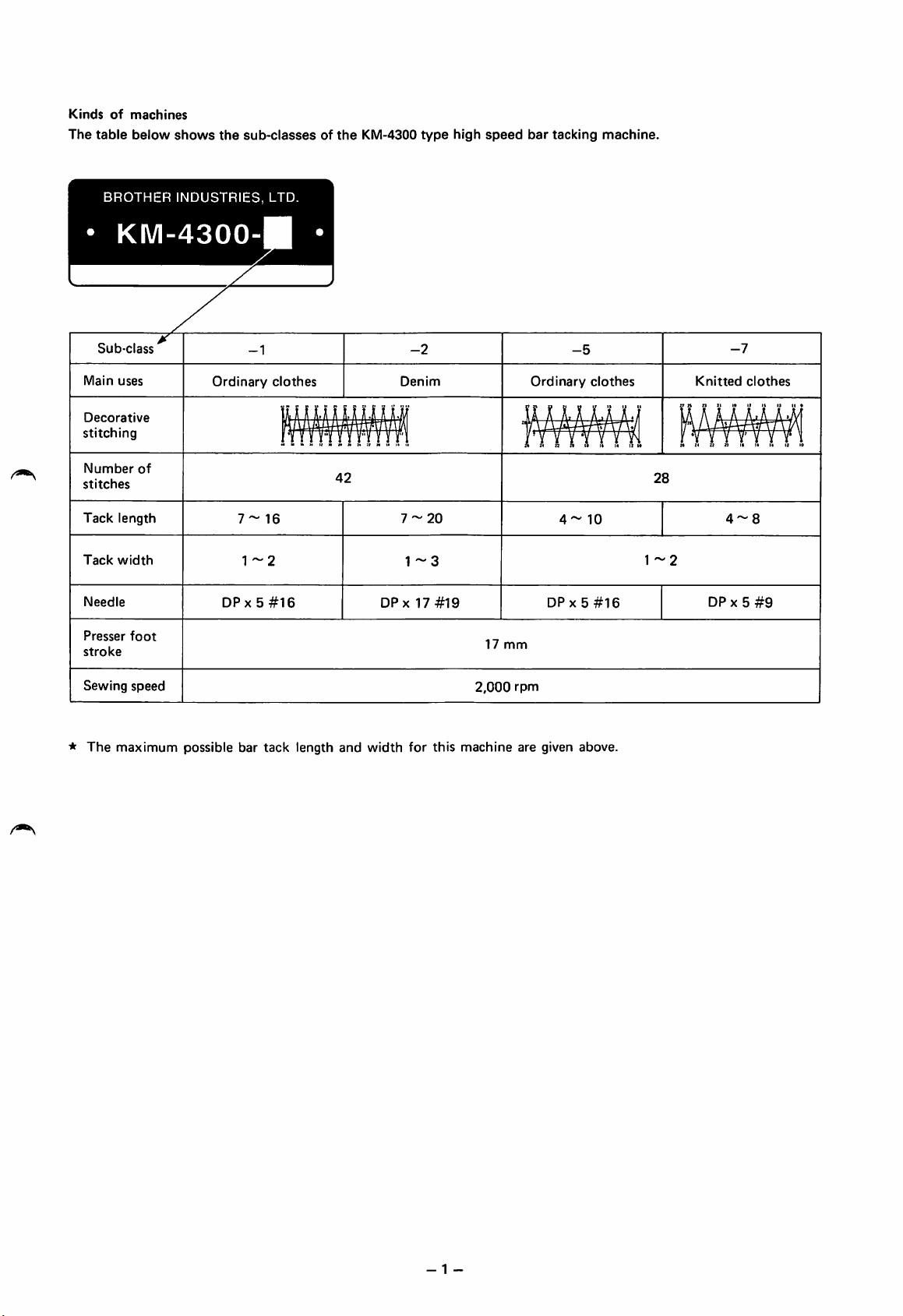
Kinds
The
of
table
machines
below
shows
the
sub-classesofthe
KM-4300
type
high
speed
bar
tacking
machine.
BROTHER
KI\/l-4300
Sub-class
Main
uses
Decorative
stitching
Number
stitches
Tack
length
Tack
width
Needle
Presser
foot
stroke
of
INDUSTRIES,
Ordinary
7-16
1-2
DPx5#16
-1
LTD.
clothes
1
Knitted
DP
4-8
-7
X 5
clothes
#9
42
-2
Denim
7-20
1-3
DPx17#19
-5
Ordinary
17
mm
clothes
4-10
DPx5#16
28
1
-2
*
Sewing
The
speed
maximum
possible
bar
tack
length
and
width
for
this
2,000
machine
rpm
are given
above.
- 1 -

Einteilung
In
der untenstehenden
der
Unterklasse
Nahmaschinen
Liste
ERTlTl
sind alle Unterklassen der Verriegelungsstich-Schnellnahmaschine
KI\/l-4300
angefuhrt.
Anwendung
Zierstiche
Stichzahl
Verriegelungsiange
Verriegelungsweite
Hub
des
StoffdruckerfuBes
Nahgeschwindigkeit
gewohnliche
Kleidungsstucke
pmMHnii
mmun^nruaam
TMl'B'ilB'MllWi
7-16
DP X 5
Nr.16
Denim
7-20
DP x 17
Nr.19
17
2.000/min
gewohnliche
Kleidungsstucke
DP
mm
4-10
X 5
Nr.16
Wirkwaren
DPx5Nr.9
* Die maximalen, auf dieser Maschine nahbaren Verriegelungslangen und -weiten sind oben aufgelistet.
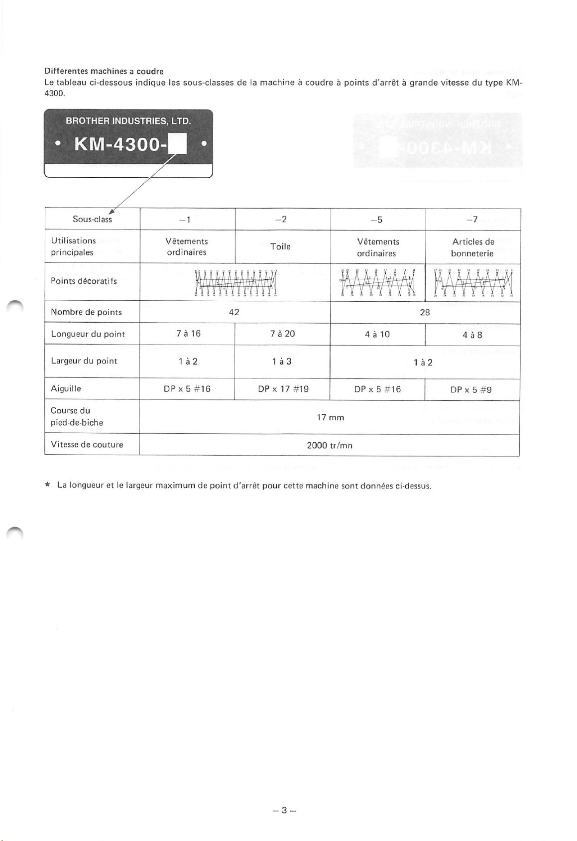
Differentes
Le
tableau
4300.
machinesacoudre
ci-dessous
indtque
les
sous-classes
delamachineacoudreapoints
d'arretagrande
vitessedutype
KM-
BROTHER
INDUSTRIES,
KM-4300-
Utilisations
principales
Points
decoratifs
Nombredepoints
Longueurdupoint
Largeurdupoint
Aiguille
LTD.
Vetements
ordinaires
7a
DPx5#16
Vetements
ordinaires
16
DFx
7 a
20
17
#19
4 a
DPx5#16
10
Articles
bonneterie
DP
X 5
de
#9
Course
du
pied-de-biche
Vitesse
de
couture
* La
longueuretle largeur
maximumdepoint
d'arret
pour
cette
17
mm
2000
machine
tr/mn
sont
donnees
ci-dessus.
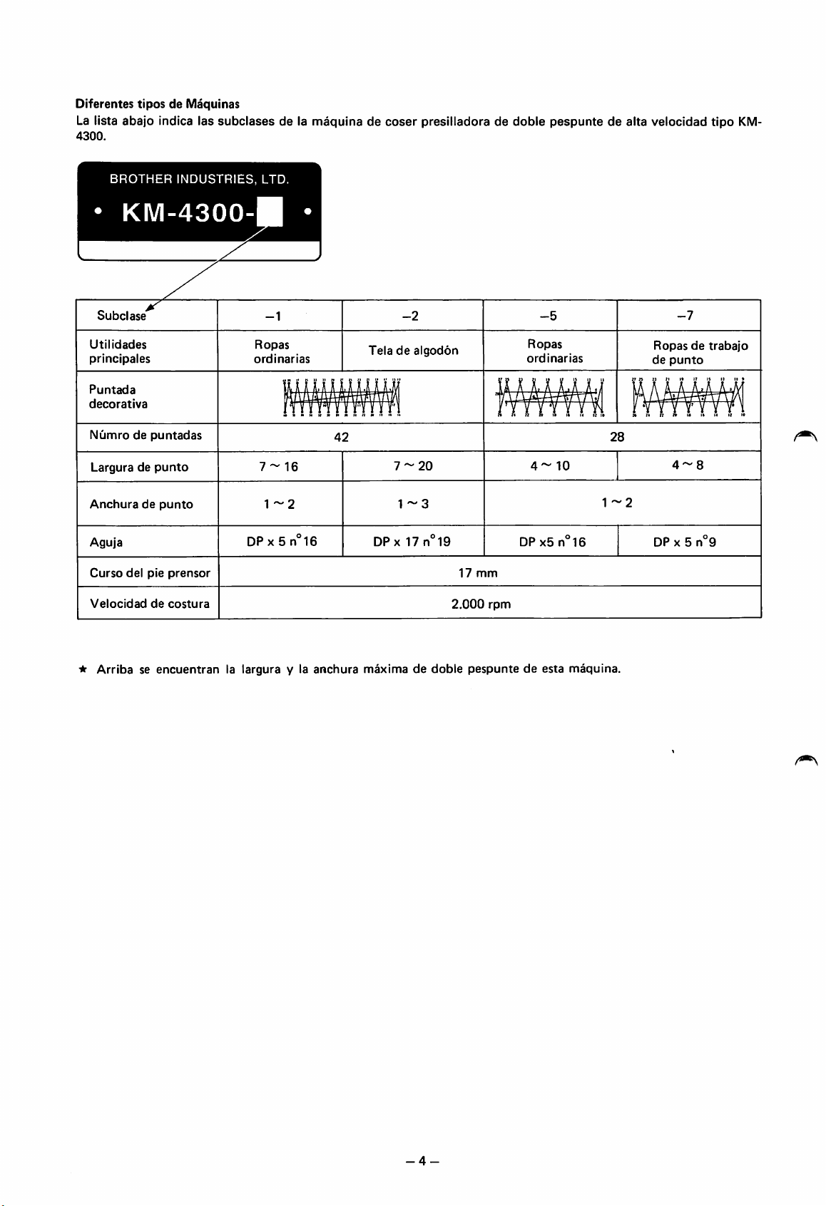
Diferentes
La lista
4300.
tipos
abajo
de Maquinas
indica las
subclases
de la
maquinadecoser
presilladora de
doble
pespunte
de alta velocidad tipo
KM-
BROTHER
INDUSTRIES,
KM-4300
Subclase
Utilidades
principales
Puntada
decorative
Numrodepuntadas
Larguradepunto
Anchuradepunto
Aguja
Curso
del
pie
prensor
LTD.
-1
Ropas
ordinaries
7-16
1-2
DPx
5 n
-2
Teladealgodon
42
7-20
1-3
16
DPx
17n19
17
mm
-5
Ropas
ordinaries
4-10
DPx5n
28
1-2
16
-7
Ropasdetrabajo
de
punto
4-8
DP
X 5 n 9
Velocidad
-At
Arribaseencuentranlalargura
de
costura
y la
anchura
maximadedoble
2.000
rpm
pespuntedeesta
maquina.
-4-

Power
table
Use
oneofthe
Motor
and
switch
assembly
ic If
purchasingamotor
lowing
types.
following special KM-4300
Single
phase
Three
phase
separately,
184-257-001 (220V)
184-258-001 (235V)
184-270-001 (220V, 380V)
184-269-001 (415V)
select
type
Model
eitherofthe
power
code
tables.
fol
Motorgesteii
Verwenden
Motorgestelle.
Motor-
und
Schaltgestell
★
Wenn
Sie
untenstehenden
Sie
einen
eins
der
einphasig
dreiphasig
Motor
separat
Motortypen:
unten
aufgelisteten
Modell-Code
184-257-001 (220V)
184-258-001 (235V)
184-270-001 (220V, 380V)
184-269-001 (415V)
kaufen,
wahlen
KM-4300-
Sie
eine
der
Single
Three
Plateau
Utiltser
Element
moteur
commutateur
ic Si le
suivants.
Monophase
Thriphase
phase
phase
delamachine
une
des
tablesdetype
~
et
moteur
est
100V
200V
Monophase
Tri
phase
achete
separement,
100V
200V
4
pole
250W
motor
4
pole
250W
motor
KM-4300
speciales
Codedemodele
184-257-001 (220V)
184-258-001 (235V)
184-270-001 (220V, 380V)
184-269-001 (415V)
choisir I'un
Quadripdie
Quadripdie
250W
250W
suivantes.
des
types
Einphasig, 100V 4
Dreiphasig, 200V 4
Mesadela
Utilizer
Conjunto
de
e
interruptor
unadelas
motor
m^quina
siguientes
Rase
Rase
unica
triple
•k Sisecompraelmotor
unodelos
Rase
Rase
unica
triple
siguientes
100V
200V
tipos.
poliger
poliger
mesas
especialesdetipo
Cddigo del
184-257-001 (220V)
184-258-001 (235V)
184-270-001 (220V, 380V)
184-269-001 (415V)
separadamente
cuatripole
cuatripole
250W-Motor
250W-Motor
modelo
habra
que
250W
250W
KM-4300
escoger
If
usingacommercially
2-016
126:0.2
65:0.2
included
appropriate
Falls
legen Sie die
bohren
'"^0
For
B43S
\
Si
pourlamachine,
la
machineetpercer
Si se
que
hacer
RlOv
R)7
>
-5
table
holes.
ein
handlesiiblicher
mitgelieferte
Sie
die
entsprechenden
une
table
quelconque
usa
una
mesa
colocarlalamina
los
agujeros
sheet
on
placer
sur
les
trous
adquisible
incluidaenla
en los lugares
available
the
table
Nahtisch
Vorlage
Locher.
est
utilisee
celle-ci le
necessaires.
enelmercado,
apropiados.
table,
place
and
make
verwendet
auf
den
Tisch,
comme
tapis
support
fourni
mesayproceder
the
the
wird,
und
avec
habra
a
Center
Motormittellinie
Centredemoteur
Centro
del
motor
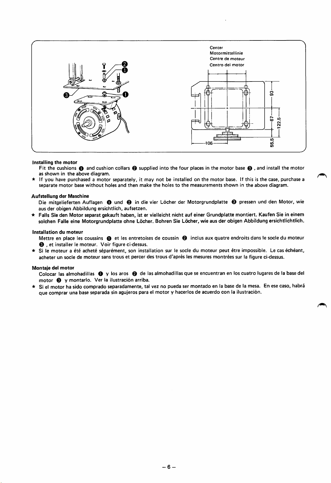
Installing
* If
Aufstellung
the
Fit
the
cushions
as
showninthe
you
have
separate
motor
O
above
purchasedamotor
motor
base
without
der
Maschine
cushion
diagram.
holes
collars Q
supplied
separately,itmay
and
then
make
into
not
be installed on
the
holestothe
the
four
places in
measurements
the
the
motor
motor
base O ,
base. If
showninthe
thisisthe
and
above
install
case,
diagram.
the
motor
purchase
Die mitgelieferten Auflagen O und O in die vier Locher der Motorgrundplatte €) pressen und den Motor, wie
aus
der
obigen Abbildung ersichtlich,
aufsetzen.
* Falls Sie den Motor separat gekauft haben, ist er vielleicht nicht auf einer Grundplatte montiert. Kaufen Sie in einem
solchen Falle eine Motorgrundplatte ohne Locher. Bohren Sie Locher, wie aus der obigen Abbildung ersichtlichtlich.
Installation
Mettre en place les coussins O ^t les entretoises de coussin 0 inclus aux
e , et installer le
* Si le
acheter
Montaje
Colocar las almohadillas O Y los aros 0 de las almohadillas
motor
du
moteur
moteuraete
un socle de
del
motor
0 y
montarlo.
moteur.
achete
moteur
Voir figure ci-dessus.
separement,
sans
Ver la
ilustracion
son
trousetpercer
installation
des
arriba.
sur le socledumoteur
trous
d'apres
les mesures
queseencuentran
quatre
peut
montrees
en los
endroits dans le socle du moteur
etre
impossible. Le cas
echeant,
sur la figure ci-dessus.
cuatro
lugares de la base del
* Si el motor ha sido comprado separadamente, tal vez no pueda ser montado en la base de la mesa. En esecaso, habra
que comprar una base separada sin agujeros para el motor y hacerlosde acuerdo con la ilustracion.
a
-6-
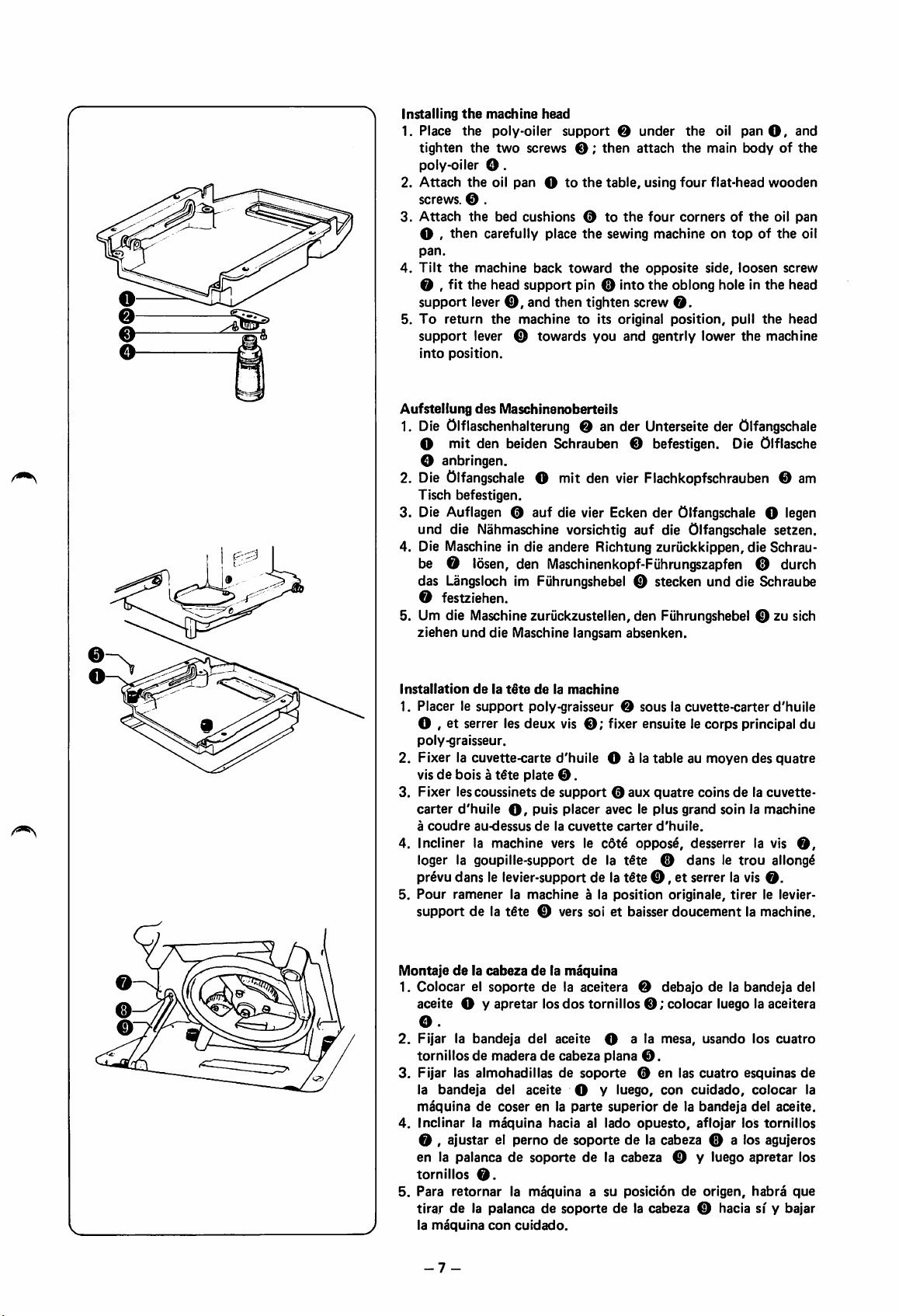
Installing
1. Place
tighten
the
the
the
machine
poly-oiler
two
screws
head
support
O;
then
O
under
attach
the
the
oil
main
panO,
bodyofthe
poly-oiler O •
2.
Attach
screws. 0 .
3.
Attach
O ,
pan.
4.
Tilt
0 , fit the head
support lever0,and then tighten screw
5.
To
the
the
then
carefully place
the
machine
return
oil
panOto
the
bed cushions 0
the
back
toward
support
the
machinetoits original
pin 0 into
table,
to
the
sewing
the
using
four
flat-head
four
corners of
the
machineontopofthe
opposite
the
side,
loosen
oblong hole in
0.
position,
pull
the
support lever 0 towards you and gentrly lower the machine
into
position.
and
wooden
oil pan
screw
the
head
head
oil
Aufsteliung
des
Maschinenoberteils
1. Die Olflaschenhalterung 0 an der Unterseite der Olfangschale
O mit den beiden Schrauben 0 befestigen. Die Olflasche
O anbringen.
2. Die Olfangschale O mit den vier Ftachkopfschrauben 0 am
Tisch befestigen.
3. Die Auflagen 0 auf die vier Ecken der Olfangschale O legen
und die Nahmaschine vorsichtig auf die Olfangschale setzen.
4. Die Maschine in die andere Richtung zuriickkippen, die Schrau-
be 0
Idsen,
den Maschinenkopf-Fiihrungszapfen 0 durch
das Lingsloch im Fiihrungshebel 0 stecken und die Schraube
0
festziehen.
5. Um die Maschine zuruckzustellen, den Fiihrungshebel 0 zu sich
ziehen
und
die Maschine langsam
Installation
1. Placer le
9
O , et serrer les
poly-graisseur.
2. Fixer la cuvette-carte
visdeboisat€te
3.
Fixer
carter
a
delatStedela
support
machine
poly-graisseur 0 sous la
deux
vis0;fixer ensuite le corps principal du
d'huile
plate
0.
lescoussinetsdesupport0aux
d'huile
coudre
O,
au-dessus
puis
placer
delacuvette
4. Incliner la machine vers le
loger la goupilie-support de la t€te 0 dans le
prevu dans le levier-supportde la t€te0,et serrer la vis
5.
Four
ramenerlamachine
support
de la
t§te
0 vers soi et baisser
absenken.
O a la
avecleplus
carter
cdte
a la
position
cuvette-carter
tableaumoyen
quatre
coinsdela
grand
soinlamachine
d'huile.
d'huile
des
cuvette-
oppose, desserrer la vis
trou
allonge
0.
originale,
doucement
tirer
le levier-
la machine.
quatre
0,
Montajedela
1. Colocar el
aceite
O.
2.
Fijar la
tornillosdemaderadecabeza
3.
Fijar
la
bandeja
maquinadecoser
4.
Inclinarlamaquina
0 , ajustar el
cabezadela
soporte
O y
apretar
bandeja
las
almohadillasdesoporte
del
maquina
de la aceitera 0
los
dos
del
aceite
aceite
en la
hacia al lado
pernodesoporte
tornillos0;colocar
O a la mesa,
plana
0.
0
O y luego,
parte
superiordela
opuesto,
de la cabeza 0 a los agujeros
en la palanca de soporte de la cabeza 0 y luego apretar los
tornillos
5.
Para
tirardela palanca de
la
-7
0.
retornarlamaquina
maquina
con
cuidado.
-
a su
soporte
posicidndeorigen,
de la
debajo
en
con
cabeza
de la bandeja del
luego la aceitera
usando
las
cuatro
cuidado,
bandeja
aflojar los
0 hacia sf y
los
cuatro
esquinas
colocar
del
aceite.
tornillos
habra
de
la
que
bajar
o
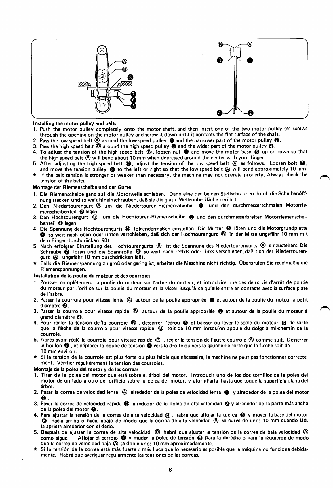
Installing
1. Push
2.
3.
4. To adjust the tension of the high speed belt
5. After adjusting the
* If
Montage
the
motor
pulley
and
the
motor
pulley
through
Pass
Pass
the
opening on the motor pulley and screw it down until it contacts the flat surface of the shaft.
the low speed belt ® around the low speed pulley O and the narrower part of the motor pulley
the high speed belt ® around the high speed pulley 0 and the wider part of the motor pulley O-
belts
completely
onto
the
motor
shaft,
and
then
insert
oneofthe
©,
loosen nut © and move the motor base © up or down so that
two
motor
the high speed belt © will bend about 10 mm when depressed around the center with your finger.
high
speed belt
and move
the
tensionofthe
the
tension pulley © to
belt tension is stronger or weaker than necessary, the machine may
belts.
der
Riemenscheibe
und
der
®,
the
Gurte
adjust the tension of the low speed belt ® as
left or right so
that
the
low speed belt ® will bend approximately 10 mm.
not
operate properly. Always check the
follows.
pulley
0.
Loosen
set
screws
bolt
O,
1. Die Riemenscheibe ganz auf die Motorwelle schieben. Dann eine der beiden Stellschrauben durch die Scheibenoff-
nung stecken und so weit hineinschrauben, daU sie die glatte Wellenoberflache beriihrt.
2. Den Niedertourengurt ® um die NIedertouren-Riemenscheibe O und den durchmesserschmalen Motorrie-
menscheibenteil
3. Den
4.
Hochtourengurt
benteil O legen.
Die
Spannungdes Hochtourengurts ©
0 legen.
© um die Hochtouren-Riemenscheibe 0
folgendermaBen
einstellen;
und
den durchmesserbreiten Motorriemenschei-
Die
Mutter ©
losen
und die Motorgrundplatte
© so weit nach oben oder unten verschieben, daB sich der Hochtourengurt © in der Mitte ungefahr 10 mm mit
dem
Finger
5.
Nach
durchdriicken
erfolgter
Einstellung
laBt.
des
Hochtourengurts
© ist
die
Spannung
des
Niedertourengurts®einzustellen:
Die
Schraube © losen und die Spannrolle ® so weit nach rechts oder links verschieben,daB sich der Niedertouren
gurt
® ungefahr 10 mm durchdriicken laBt.
* Falls die Riemenspannung zu
Riemenspannungen.
Installationdela
1. Pousser
du
moteur
de
I'arbre.
2. Passer la courroie
diametre
3.
Passer
grand
4. Pour
diametre
r^gler
pouliedumoteuretdes
completementlapouliedumoteur
par
I'orifice
pour
0.
la courroie pour
O.
la tension
groB
oder gering ist, arbeitet die
courroles
sur
la poulie du
vitesse lente ®
vitesse
rapide © autour de la poulie appropriee 0 et autour de la poulie du moteur d
dela
courroie © , desserrer I'ecrou © et
sur I'arbre du
moteur
autour
et la visser
de la poulie appropri^e O et
Maschine
moteur,etintroduire
jusqu'dcequ'elle
nicht richtig. Qberprufen Sie
entreencontacte
baisseroulever
regelmaBig
une
des
deux
vis
d'arretdepoulie
avec la
autour
de la poulie du
moteur
le socle du moteur © de sorte
surface
die
plate
a petit
que la fidche de la courroie pour vitesse rapide © soit de 10 mm lorsqu'on appuie du doigt b mi-chemin de la
courroie.
5. Apres avoir
r6gl6
la courroie pour vitesse rapide © , regler la tension de I'autre courroie ® comme suit. Desserrer
le boulon 0 , et d^placer la poulie de tension © vers la droite ou vers la gauche de sorte que la fleche soit de
10
mm
* Si la tension de la courroie est plus
Montajedela
1.
Tirardela
environ.
ment.
Verifier regulierement la
polea
motordeun
arbol.
polea
ladoaotro
del
motoryde
del
motor
del
tension
las
que
orificio
forte
des courroies.
correas
esta
sobreelarbol
sobrelapolea
ou plus faible que necessaire, la machine ne
del
motor.
del
motor,yatornillaria
Introducir
unodelos
hasta
peut
pas
fonctionner
dos
que
tornillosdela
toquelasuperficie
correcte-
polea
del
plana
del
2. Pasar la correa de velocidad lenta ® alrededor de la polea de velocidad lenta O y alrededor de la polea del motor
0
3.
Pasarlacorreadevelocidad
de
la polea del
motor
©.
rapida
alrededordela
poleadealta
velocidad
0 y
alrededordela
parte
mas
ancha
4. Para ajustar la tension de la correa de alta velocidad @ , habra que aflojar la tuerca © y mover la base del motor
© hacia arriba o hacia
la
aprieta
alrededor
abajodemodo
coneldedo.
quelacorrea
de alta velocidad (D se curve de
unos
10 mm
cuando
Ud.
5. Despu^s de ajustar la correa de alta velocidad © habra que ajustar la tension de la correa de baja velocidad ®
como sigue. Aflojar el cerrojo 0 y mudar la polea de tensidn © para la derecha o para la izquierda de modo
quelacorrea
* Si la
mente.
tensiondela
de velocidad baja ® se
que
correa
averiguar
Habra
esta
mas
regularmente
doble
unos
fuerteomas
las
tensionesdelas
10 mm
aproximadamente.
flaca
quelonecesarioesposible
correas.
quelamaquinanofuncione
debida-
-8-
Motor
pulley
The
maximum
should
be usedata
1,800or2,300
Frequency
50
Hz
60
Hz
and
belts
rpmofthis
speedof2,000
rpm
motor
sewing
pulley
Sewing
2,300
2.000
1,800
2,300
2,000
1,800
machineis2,300.
rpmtoprevent
and
belts,
speed
purchase
Motor
154540-0-01
153109-0-01
154541-0-01
153108-0-01
But if
the
thread
oneofthe
pulley
synthetic
from
following
fiber
is used
breaking
models
High
speed
082105-2-90
082105-1-90
082105-1-90
082105-0-90
for
through
separately.
belt
(in.)
(52)
(51)
(51)
(50)
the
cloth
and
overheating. If
Low
thread,
you
wishtouse a
speed
082104-8-91
the
belt
machine
(in.)
(48)
Motorriemenscheibe
Die maximale Drehzahl dieser Nahmaschine ist
und
Gurte
2.300
U/min.
Aber
wenn
Stoff
und
Faden aus
Synthetics
sind, sollte
die Maschme mit 2.000/min arbeiten, damit der Faden nicht durch Oberhitzung reiBt. Um die Maschine mit 1.800/min
Oder
2.300/minzubetreiben,
untenstehenden
Netzspannungsfrequenz
50
60
Pouliedumoteuretcourroies
Le
nombre
tissu en
due
de
La
Las
fibre
au surchauffage.
moteuretdes courroies
Frequence
50
Hz
60
Hz
polea
revoluciones
del
Hz
Hz
de
motor
Liste
aus:
tours-minute
synthetique
Acheter
Vitessedecouture
2.300
2.000
1.800
2.300
2.000
1.800
y las
maximas
wahlen
Nahgeschwindigkeit
maximum
la vitesse
Sie
die
2.300
2.000
1.800
2.300
2.000
1.800
de
recommandee
Motorriemenscheibe
cette
s^parementundes
pour
les vitesses
1.800ou2.300
Pouliedemoteur
154540-0-01
153109-0-01
154541-0-01
153108-0-01
correas
por minuto de esta maquina
Motorriemenscheibe
154540-0-01
153109-0-01
154541-0-01
153108-0-01
machineacoudre
de la
machine
meddles
mentionnes
tr/mn.
Courroie
Megan
a 2.300. En el caso cuando se usa hilo y tela de fibra
und
die
Hochtourengurt
est
2.300
estde2.000
ci-dessous, s'il
pour
vitesse
082105-2-90
082105-1-90
082105-1-90
082105-0-90
Gurte
(als
082105-2-90
082105-1-90
082105-1-90
082105-0-90
tr/mn.
tr/mn
rapide
(52)
(51)
(51)
(50)
Sonderzubehbr
(Zoll)
(52)
(51)
(51)
(50)
Danslecas
pour
empficher
est
necessaire
Courroie
(po.)
erhaltlich) aus
Niedertourengurt
082104-8-91
d'utilisation
toute
rupture
d'utiliser
pour
vitesse
082104-8-91 (48)
(48)
une
lente
(Zoll)
de
poulie
der
fil
de fil
(po.)
sintetica la velocidad recomendada es de 2.000 rpm a fin de evitar que el hilo se rompa por causa de acaloramiento
excesivo. Si hay necesidad de usar una polea de motor y correasde velocidad de 1.800 o 2.300 rpm, habraque comprar
unodelos
Frecuencia
50
60
modelos
Hz
Hz
siguientes:
Velocidad
2.300
2.000
1.800
2.300
2.000
1.800
de
costura
Polea
del
154540-0-01
153109-0-01
154541-0-01
153108-0-01
motor
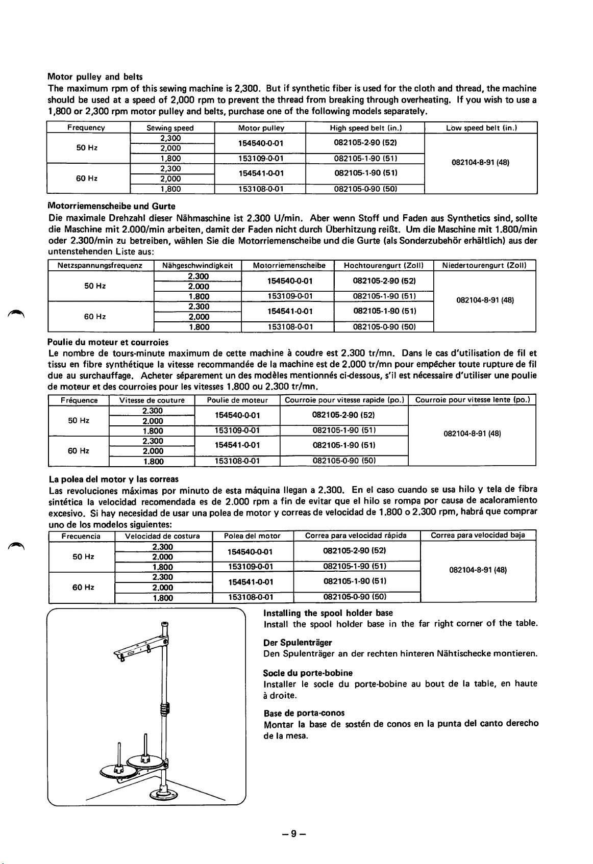
Installing
Correa
the
para
082105-2-90
082105-1-90
082105-1-90
082105-0-90
spool
holder
velocidad
(52)
(51)
(51)
(50)
base
rapida
Correa
para
velocidad
082104-8-91
baja
(48)
Install the spool holder base in the far right corner of the table.
et
Der
Spulentrager
Den
Spulentragerander
rechten
hinteren
Socleduporte-bobine
Installerlesocle
a
droite.
Basedeporta-conos
du
porte-bobine
au
Montar la base de sosten de conos en la
delamesa.
-9-
Nahtischecke
boutdela
punta
montieren.
table,enhaute
del
canto
derecho
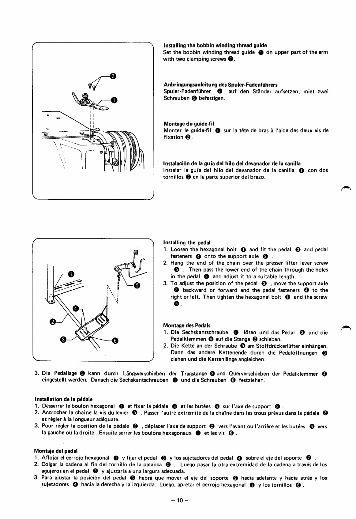
Installing
Set
the
the
bobbin
bobbin
winding
winding
with two clamping screws
thread
O.
thread
guide O
guide
on
upper
partofthe
arm
Anbringungsanleitung
des
Spuler-Fadenfiihrers
Spuler-Fadenfuhrer O auf den Stander aufsetzen, miet zwei
Schrauben
Montageduguide-fil
Monter
fixation
Instalaciondela gui'a del
Instalar
tornillos0enlaparte
Installing
1.
Loosen
fasteners
2.
Hang
in
3.Toadjust
O befestigen.
le guide-fil O
la gui'a
the
the
O
the
del
pedal
hexagonal
onto
endofthe
0 . Then pass
the
pedal 0 and adjust it to a suitable length.
the
surlat§tedebras
hilo
del
hilo
del
devanador
superior
bolt
the
support
chain
the
lower end of the chain through
positionofthe
devanadordela canilla
delacanilla
del
brazo.
O
and
fit
axle
0 .
over
the
pedal 0 ,
a I'aide
the
presser
move
pedal
des
lifter
the
deux
O
0
and
lever
the
support
con
vis
dos
pedal
screw
holes
axle
0 backward or forward and the pedal fasteners O to the
right or left.
0.
Then
tighten
the
hexagonal
bolt
O
and
the
screw
de
Montage
1.
des
Pedals
Die
Sechskantschraube
O
Ibsen
und
das
Pedal
0
und
die
Pedalklemmen O auf die Stange 0 schieben.
2. Die Kette an der Schraube 0 am Stoffdriickerliifter einhangen.
Dann das andere Kettenende durch die Pedalbffnungen 0
ziehen
und
die Kettenlange angleichen.
3. Die Pedallage 0 kann durch Langsverschieben der Tragstange 0 und Querverschieben der Pedalklemmer O
eingestellt
Installationdela
werden.
pedale
Danach
die
Sechskantschrauben
O
und
die
Schrauben
0 festziehen.
1. Desserrer le boulon hexagonal O et fixer la pedale 0 et les but^es O sur I'axe de support 0 .
2. Accrocher la chalne la vis du levier 0 . Passer I'autre extr6mit6 de la chaine dans les trous prevus dans la pedale ©
et
r§gler a la
longueur
adequate.
3. Pour r^gler la position de la pedale 0 , deplacer I'axe de support 0 vers I'avant ou I'arriere et les butees O vers
la gauche ou la droite. Ensuite serrer les boulons hexagonaux O et les vis 0 .
Montaje
del
pedal
1. Aflojar el cerrojo hexagonal O y fijar el pedal 0 y los sujetadores del pedal O sobre el eje del soporte 0 .
2. Colgar la
cadena
al fin del
tornillo
de la palanca 0 . Luego pasar la
otra
extremidaddela
cadenaatravesde
los
agujeros en el pedal 0 y ajustaria a una largura adecuada.
3. Para ajustar la posicion del pedal 0
habra
que
mover el eje del
soporte
0 hacia
adelante
y hacia
atras
y los
sujetadores O hacia la derecha y la izquierda. Luego, apretar el cerrojo hexagonal O y los tornillos 0 .
-
10-

0
O0
Si
For sewingmachinesequipped with mechanicaltwo-pedal systems
1. Loosen
2. Attach
the
flat-head screwO,then remove the metal washer©,and the power pulley
the
hexagonal bolts O to
the
drive lever
0;
attach
the
drive lever plateO.metal washersO,and
0.
the
nuts
0 , to the tips of the hexagonal bolts.
the
3. Attach the clutch tension spring ® to
4. Attach
the
drive lever tension spring 0 to
second hole.
the
drive lever plate, and
the
clutch tension spring
mount.
5. Loosen the hexagonal bolt 0 , and attach the pedals 0 , and the pedal fasteners 0 , to the support axle 0 .
6. Hook
7.
the
and
chain to
adjustittoanappropriate
Hook
the
adjustittoanappropriate
other
the
presser lifter lever screw 0 , then pass
chaintothe
length.
drive lever
length.
plate0,then
pass
the
the
lower end through
lower
end
through
the
the
hole in
hole in
the
right-hand pedal
the
left-hand pedal,
and
S Nahmaschinen, die mit zwei mechanisch betatigten Pedalenausgeriistet sind
1. Die Flachkopfschraube O losen, die Unter lagscheibe 0 und die Antriebsscheibe 0 entfernen.
2. Die Sechskantschrauben Q am Betatigungshebel 0 anbringen. Den Hebel 0 und die Unterlagscheiben 0 aur die
Sechskantschrauben
3.
Die
Kupplungsfederamzweiten
stecken
und
die
Muttern0festziehen.
Loch
einhangen.
4. Die Betatigungshebelfeder 0 am Hebel und an der Aufhangung der Kupplungsfeder anbringen.
5. Die Sechskantschraube 0 losen, die beiden Pedale 0 und die Pedalklemmen 0 auf die Stange 0 schieben.
6. Die Kette an der Schraube 0 einhangen. Die Kettenenden durch die Locher des rechten Pedals ziehen
richtige Kettenlange einstellen.
7. Die andere Kette am Hebel 0 einhangen. Die Kettenenden durch die Locher des linken Pedals ziehen
richtige Kettenlange einstellen.
Pour
les machines a
1. Desserrer la vis a tSte plateO,retirer ensuite la rondelle metallique 0 et la poulie de commande
2.
Fixer
les
boulons
rondelles metalliques 0etles Serous 0
3. Fixer le ressort de tension de I'embrayage 0 au deuxiSme
4.
Fixer
le ressort de
ressortdetensiondeI'embrayage.
coudre
possedant un systdma a
hexagonaux
tension
O au levier
0
du
deux
p6dales
d'entraTnement
aux
extremites
levier
d'entraTnementauplateauduleveir
des
micaniques
0;
boulons
trou.
fixerleplateau0du
hexagonaux.
d'entraTnementeta la
0.
levier
d'entrainement,
und
und
monture
5. Desserrer le boulon hexagonal 0 , et fixer les pedales 0 ainsi que les arr^ts 0 de pedale a I'axe de soutien 0 .
6. Accrocher la chaTne la visdulevier 0 . Passer ensuite I'extremite inferieure de la chaTne
pddale de
7.
Accrocher
dansletrou
droiteetregler a la
I'autre
chaTne au
situ§
danslap^ale
longueur
plateau0du
appropriee.
levier
d'entraTnement;
de gaucheetregler a la longueur appropriee.
passer
ensuit
I'extremite
dansletrou
inferieuredela chaTne
situ§
dans
SB Para maquinas de coser equipadas con sistemas mecdnicos de dos pedales
1. Aflojar el tornillo de cabeza plena
2.
Colocar
arandelas
3.
Colocarelmuelle
4.
Colocarelmuelle
tensordeembrague.
5. Apretar el perno
los
pernos
metalicas0,y las
hexagonales O en la palancademando
tensordeembraque
tensordela
hexagonal
tuercas0,en los
0 y colocarlos pedales
0,
quitar
0 en
palancademando
extremosdelos
segundo
la arandela metalica0,y hacer girar la polea
0,
orificio.
0 en la placadela
0,
pernos
y los retenesde los pedales 0 en el ejede soporte
colocar
la place de la palancademando
hexagonales.
palancademando,
y en la
0.
montura
del
0,
muelle
0.
6. Enganchar la cadena al collar de colocacion de la cadena 0 , pasar el extremo inferior a traves del orificio del pedal
derecho,yajustarlo
7. Enganchar la
pedal izquierdo, y ajustarlo a la longitud
otra
a la
longitud
cadena
adecuada.
a la placa de la palanca de
adecuada.
mando
0 , pasar el
extremo
inferior a traves del orificio del
die
die
les
du
la
las
-11-
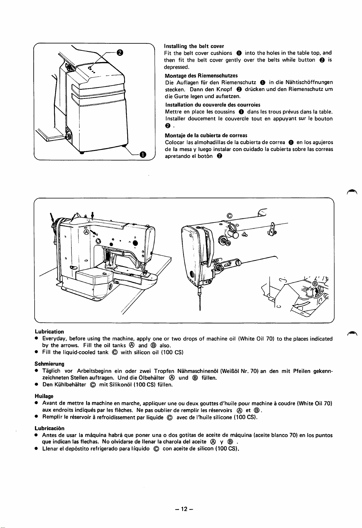
Installing
Fit
then
depressed.
Montage
Die Auflagen fiir
stecken,
die
Installation
Mettreenplace
Installer
O
Montajedela
Colocar
delamesayluego
apretandoelboton
the
belt
cover
the
belt
cover
cushions
fit the belt cover gently over
des
Riemenschutzes
den
Dann
den
Knopf
Gurte
legen
und
aufsetzen.
du
couvercle
les
coussins
doucementlecouvercle
cubiertadecorreas
las
almohadillasdela
instalar
O
O
into
Riemenschutz
O driicken
des
courroies
O
dans
cubiertadecorrea
con
cuidadolacubierta
the
holesinthe
the
belts while
O in
die
Nahtischoffnungen
und
den
Riemenschutz
les
trous
prevus
toutenappuyant
Q
table
top,
button
danslatable.
surlebouton
sn
los
agujeros
sobre
las
and
O is
um
correas
Lubrication
• Everyday, before using
by the arrows. Fill the oil tanks
• Fill
the
liquid-cooled tank
Schmierung
• Taglich vor Arbeitsbeginn ein
the
machine,
<§)
apply
(S)
and ® also.
with silicon oil (ICQ CS)
oder
zwei
oneortwo
Tropfen
drops
of machine oil (White Oil 70)tothe
Nahmaschinendl (WeiBol Nr. 70) an den
zeichneten Stellen auftragen. Und die Olbehalter (§) und (g) fullen.
• Den Kuhlbehalter ©
Huilage
• Avant de
mettre
aux endroits indiqu^s par les fleches. Ne pas oublier de remplir les reservoirs (g)
mit
Silikondl
(100
CS) fullen.
la machine en marche, appliquer une ou
deux
gouttes
d'huile
pour
et©.
• Remplir le reservoir a refroidissement par liquide © avec de I'huile silicone (100 CS).
Lubrlcacion
•
Antesdeusar la
que
indican las flechas. No olvidarse de llenar la charola del aceite (g) y © .
• Llenar el
depostito
maquina
habra
refrigerado para
que
poner
liquido
unaodos
©
con
gotitasdeaceitedemaquina
aceite de silicon
-12-
(100
CS).
machine a
(aceite
bianco
places indicated
mit
Pfeilen gekenn-
coudre
(White Oil 70)
70) en los
puntos
 Loading...