

Page 1
KE-430FX
Basic Operation Manual
KE-430FS
BE-438FX
ELECTRONIC DIRECT DRIVE LOCKSTITCH BAR TACKER
ELECTRONIC DIRECT DRIVE LOCKSTITCH BUTTON SEWER
Please read this manual before using the machine.
Please keep this manual within easy reach for quick reference.
This basic operation manual describes basic
operations including sewing machine operations.
For cleaning, standard adjustments and more details,
please refer to the instruction manual contained in
the Document CD.
Page 2

Thank you very much for buying a BROTHER sewing machine. Before using your new machine,
please read the safety instructions and the explanations given in the instruction manual.
With industrial sewing machines, it is normal to carry out work while positioned directly in front of moving parts
such as the needle and thread take-up, and consequently there is always a danger of injury that can be caused
by these parts. Follow the instructions from training personnel and instructors regarding safe and correct
operation before operating the machine so that you will know how to use it correctly.
KE-430FX/KE-430FS, BE-438FX
Page 3
SAFETY INSTRUCTIONS
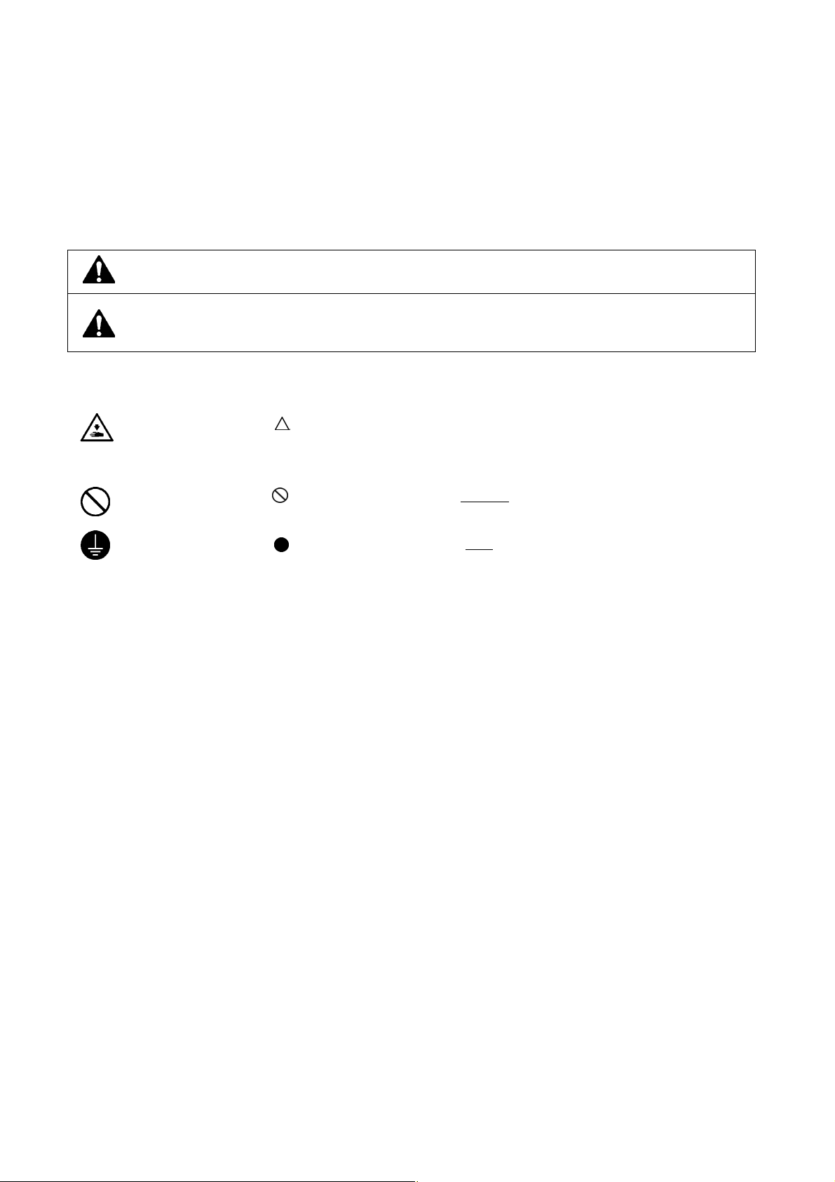
1. Safety indications and their meanings
This instruction manual and the indications and symbols that are used on the machine itself are provided in order to ensure
safe operation of this machine and to prevent accidents and injury to yourself or other people.
The meanings of these indications and symbols are given below.
Indications
DANGER
CAUTION
Symbols
・・・・・・
This symbol ( ) indicates something that you should be careful of. The picture inside the triangle
indicates the nature of the caution that must be taken.
(For example, the symbol at left means “beware of injury”.)
The instructions which follow this term indicate situations where failure to follow the
instructions will result in death or serious injury.
The instructions which follow this term indicate situations where failure to follow the
instructions could cause injury when using the machine or physical damage to equipment
and surroundings.
・・・・・・
・・・・・・
This symbol ( ) indicates something that you must not do.
This symbol ( ) indicates something that you must do. The picture inside the circle indicates the
nature of the thing that must be done.
(For example, the symbol at left means “you must make the ground connection”.)
KE-430FX/KE-430FS, BE-438FX
i
Page 4
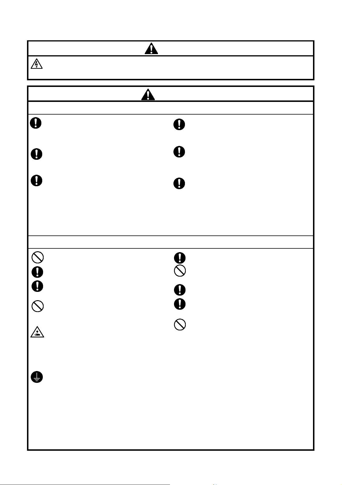
2. Notes on safety
Wait at least 5 minutes after turning off the power switch and disconnecting the power cord from the wall outlet
before opening the face plate of the control box. Touching areas where high voltages are present can result in
severe injury.
DANGER
CAUTION
Environmental requirements
Use the sewing machine in an area which is free from
sources of strong electrical noise such as electrical
line noise or static electric noise.
Sources of strong electrical noise may cause
problems with correct operation.
Any fluctuations in the power supply voltage should
be within ±10% of the rated voltage for the machine.
Voltage fluctuations which are greater than this may
cause problems with correct operation.
The power supply capacity should be greater than the
requirements for the sewing machine’s power
consumption.
Insufficient power supply capacity may cause
problems with correct operation.
Installation
Machine installation should only be carried out by a
qualified technician.
Contact your Brother dealer or a qualified electrician
for any electrical work that may need to be done.
The sewing machine weighs approximately 57 kg.
The installation should be carried out by two or more
people.
Do not connect the power cord until installation is
complete, otherwise the machine may operate if the
foot switch is depressed by mistake, which could
result in injury.
Hold the machine head with both hands when tilting it
back or returning it to its original position.
Furthermore, after tilting back the machine head, do
not push the face plate side or the pulley side from
above, as this could cause the machine head to
topple over, which may result in personal injury or
damage to the machine.
Be sure to connect the ground. If the ground
connection is not secure, you run a high risk of
receiving a serious electric shock, and problems with
correct operation may also occur.
The ambient temperature should be within the range
of 5°C to 35°C during use.
Temperatures which are lower or higher than this
may cause problems with correct operation.
The relative humidity should be within the range of
45% to 85% during use, and no dew formation should
occur in any devices.
Excessively dry or humid environments and dew
formation may cause problems with correct operation.
In the event of an electrical storm, turn off the power
and disconnect the power cord from the wall outlet.
Lightning may cause problems with correct operation.
All cords should be secured at least 25 mm away
from any moving parts. Furthermore, do not
excessively bend the cords or secure them too firmly
with staples, otherwise there is the danger that fire or
electric shocks could occur.
Install the safety covers to the machine head and
motor.
If using a work table which has casters, the casters
should be secured in such a way so that they cannot
move.
Be sure to wear protective goggles and gloves when
handling the lubricating oil and grease, so that they
do not get into your eyes or onto your skin, otherwise
inflammation can result.
Furthermore, do not drink the oil or eat the grease
under any circumstances, as they can cause vomiting
and diarrhoea.
Keep the oil out of the reach of children.
ii
KE-430FX/KE-430FS, BE-438FX
Page 5
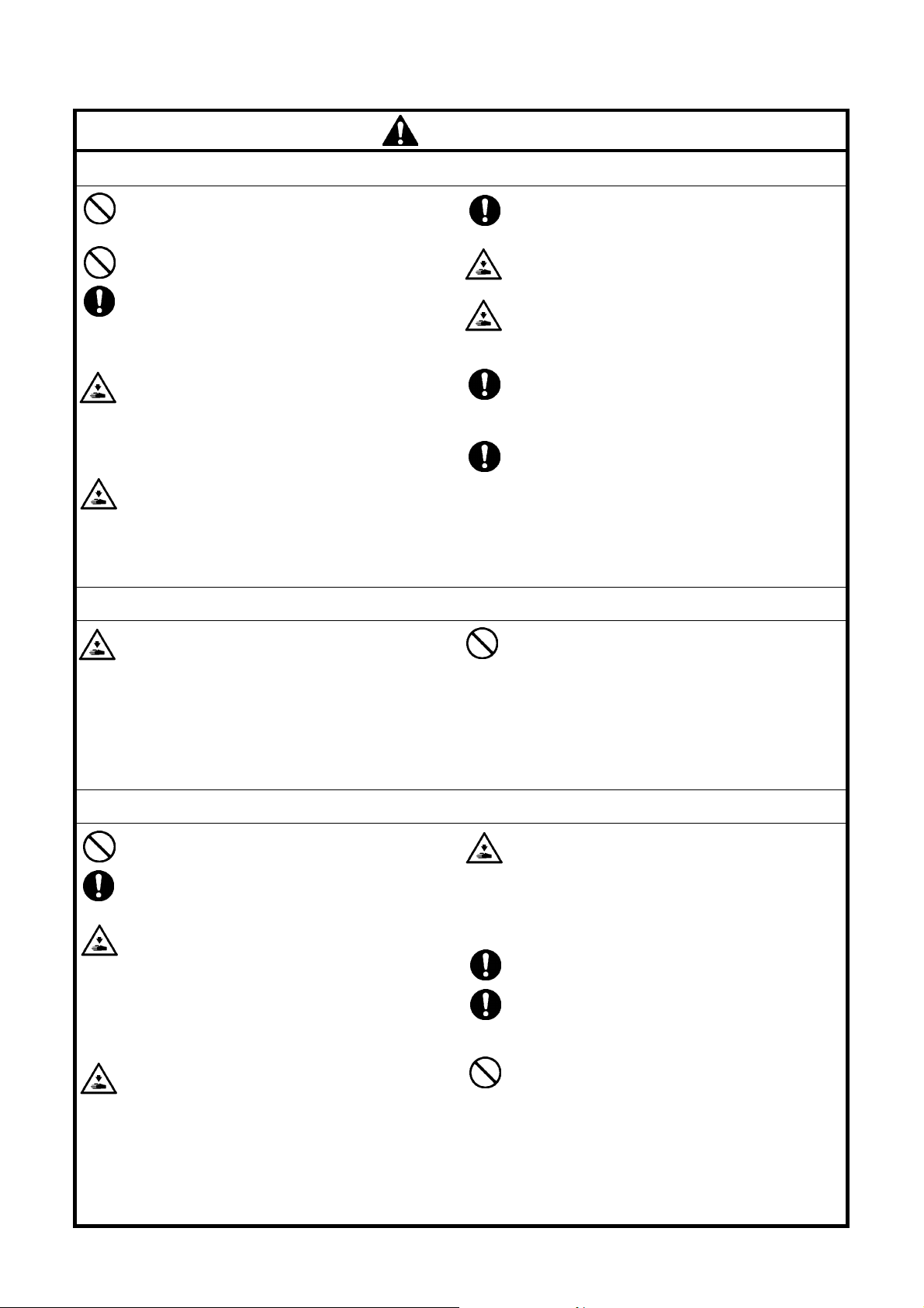
CAUTION
Sewing
This sewing machine should only be used by
operators who have received the necessary training
in safe use beforehand.
The sewing machine should not be used for any
applications other than sewing.
Be sure to wear protective goggles when using the
machine.
If goggles are not worn, there is the danger that if a
needle breaks, parts of the broken needle may enter
your eyes and injury may result.
Turn off the power switch at the following times,
otherwise the machine may operate if the foot switch
is depressed by mistake, which could result in injury.
• When replacing the needle and bobbin
• When not using the machine and when leaving the
machine unattended
Use threading mode or turn off the power first in order
to carry out threading.
Cleaning
Turn off the power switch before carrying out
cleaning, otherwise the machine may operate if the
foot switch is depressed by mistake, which could
result in injury.
If using a work table which has casters, the casters
should be secured in such a way so that they cannot
move.
Attach all safety devices before using the sewing
machine. If the machine is used without these
devices attached, injury may result.
Do not touch any of the moving parts or press any
objects against the machine while sewing, as this
may result in personal injury or damage to the
machine.
If an error occurs in machine operation, or if abnormal
noises or smells are noticed, immediately turn off the
power switch. Then contact your nearest Brother
dealer or a qualified technician.
If the machine develops a problem, contact your
nearest Brother dealer or a qualified technician.
Be sure to wear protective goggles and gloves when
handling the lubricating oil and grease, so that they
do not get into your eyes or onto your skin, otherwise
inflammation can result.
Furthermore, do not drink the oil or eat the grease
under any circumstances, as they can cause vomiting
and diarrhoea.
Keep the oil out of the reach of children.
Maintenance and inspection
Maintenance and inspection of the sewing machine
should only be carried out by a qualified technician.
Ask your Brother dealer or a qualified electrician to
carry out any maintenance and inspection of the
electrical system.
Turn off the power switch and disconnect the power
cord from the wall outlet at the following times,
otherwise the machine may operate if the foot switch
is depressed by mistake, which could result in injury.
• When carrying out inspection, adjustment and
maintenance
• When replacing consumable parts such as the
rotary hook
If the power switch needs to be left on when carrying
out some adjustment, be extremely careful to observe
all safety precautions.
KE-430FX/KE-430FS, BE-438FX
Hold the machine head with both hands when tilting it
back or returning it to its original position.
Furthermore, after tilting back the machine head, do
not push the face plate side or the pulley side from
above, as this could cause the machine head to
topple over, which may result in personal injury or
damage to the machine.
Use only the proper replacement parts as specified
by Brother.
If any safety devices have been removed, be
absolutely sure to re-install them to their original
positions and check that they operate correctly before
using the machine.
Any problems in machine operation which result from
unauthorized modifications to the machine will not be
covered by the warranty.
iii
Page 6
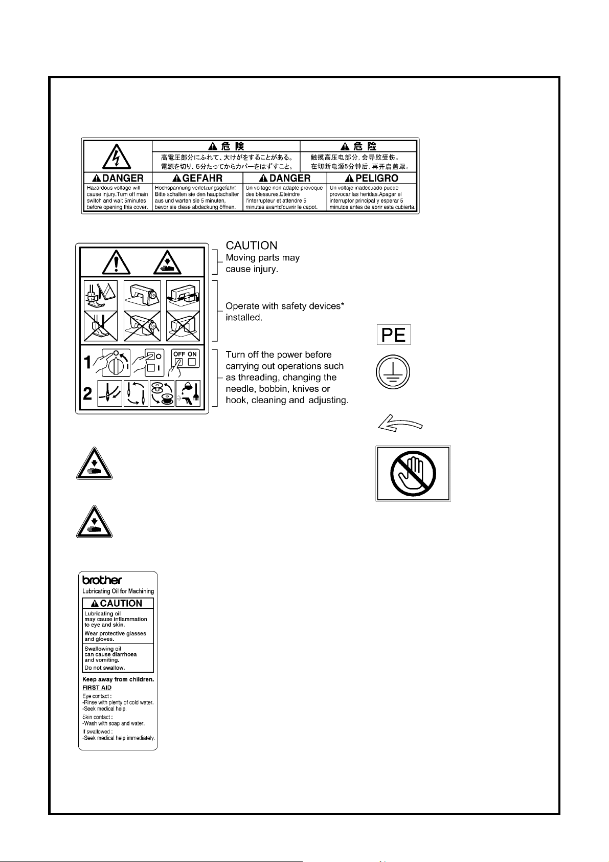
3. Warning labels
The following warning labels appear on the sewing machine.
Please follow the instructions on the labels at all times when using the machine. If the labels have been removed or are
difficult to read, please contact your nearest Brother dealer.
1
2
3
4
Be careful to avoid injury from the moving thread
take-up.
Be careful not to get your hands caught when
returning the machine head to its original position
after it has been tilted.
*Safety devices
Eye guard
Finger guard
DT solenoid cover
Thread take-up cover
Side cover
Rear cover, etc.
5
Be sure to connect the ground. If
the ground connection is not
secure, you run a high risk of
receiving a serious electric shock,
and problems with correct
operation may also occur.
6
7
Direction of operation
Do not hold, otherwise
problems with
operation or injury may
occur.
8
iv
KE-430FX/KE-430FS, BE-438FX
Page 7
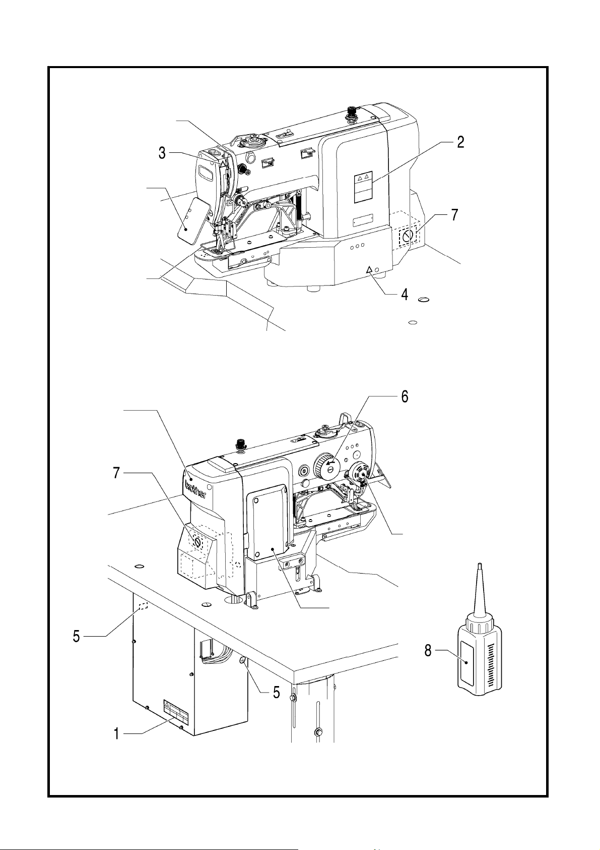
r
r
Thread take-up cove
Eye guard
Finger guard
3162B
Rear cove
DT solenoid
cover
Side cover
oil tank
2506B
3163B
KE-430FX/KE-430FS, BE-438FX
v
Page 8

CONTENTS
1. NAMES OF MAJOR PARTS ................ 1
2. USEFUL FUNCTIONS
FOR OPTIMUM SEWING ..................... 2
3. LIST OF SEWING PATTERNS ............. 3
3-1. List of sewing patterns (KE-430FX・FS) ......... 3
3-2. List of sewing patterns (BE-438FX) ................ 8
4. INSTALLATION .................................... 11
4-1. Table processing diagram .............................. 11
4-2. Installing the control box ................................. 12
4-3. Installing the oiler ............................................ 12
4-4. Installing the machine head ............................ 13
4-5. Installing the operation panel ......................... 14
4-6. Installing the cotton stand ............................... 15
4-7. Installing the button tray (BE-438FX) ............. 15
4-8. Installing the eye guard .................................. 15
4-9. Connecting the cords ...................................... 16
4-10. Connecting the ground wire ......................... 19
4-11. Installing the rear cover ................................ 20
4-12. Lubrication .................................................... 21
4-13. Connecting the power cord .......................... 22
4-14. Checking the machine head switch .............. 25
4-15. Starting up .................................................... 25
6. USING THE OPERATION PANEL
(BASIC OPERATIONS) .......................
6-1. Name and function of each
operation panel item ....................................... 34
6-2. Program setting method .................................. 36
6-3. Copying programs ........................................... 40
6-4. Checking the sewing pattern
(KE-430FX・FS) ............................................... 41
6-5. Checking the sewing pattern (BE-438FX) ...... 42
6-6. Correcting the upper thread tension
<For KE-430FX and BE-438FX> .................... 43
34
7. SEWING ............................................... 44
7-1. Sewing ............................................................ 44
7-2. Changing sewing conditions ........................... 45
Document CD ........................................... 46
5. PREPARATION BEFORE SEWING ..... 26
5-1. Installing the needle ........................................ 26
5-2. Threading the upper thread ............................ 26
5-3. Winding the lower thread ................................ 28
5-4. Installing the bobbin case ............................... 29
5-5. Thread tension ................................................ 29
5-5-1. Lower thread tension........................... 29
5-5-2. Upper thread tension........................... 30
5-6. Thread nipper device
<KE-430FX-03, -0K, -0F> ............................... 31
5-7. Inserting the button (BE-438FX) ..................... 33
5-8. Adjusting the button clamp (BE-438FX) ......... 33
5-9. Installing the accessory spring (BE-438FX) ... 33
KE-430FX/KE-430FS, BE-438FX
Page 9
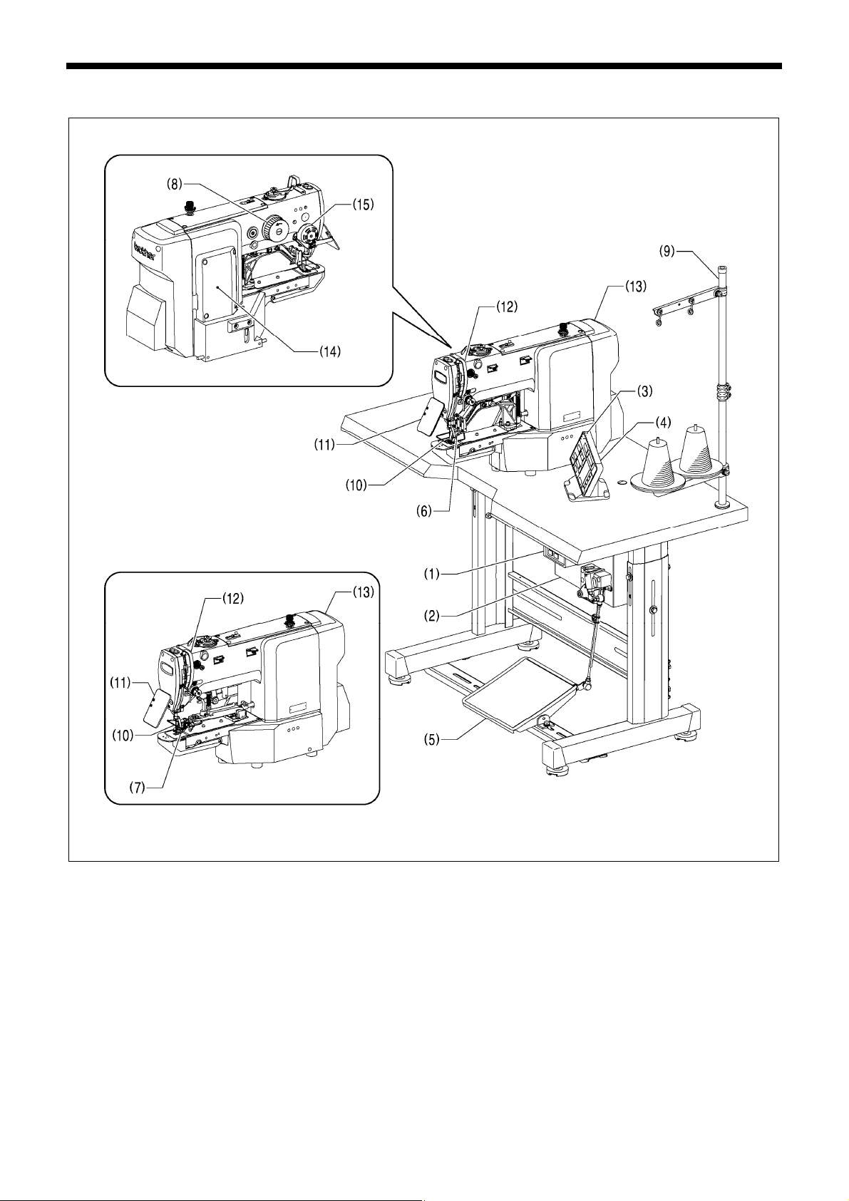
1. NAMES OF MAJOR PARTS
(1) Power switch
(2) Control box (10) Finger guard
(3) SD card slot (11) Eye guard
(4) Operation panel (12) Thread take-up cover
(5) Foot switch (13) Rear cover
(6) Work clamp (KE-430FX・FS)
(7) Button clamp (BE-438FX) (15) DT solenoid cover
(8) Pulley
(9) Cotton stand
BE-438FX
Safety devices
(14) Side cover
1. NAMES OF MAJOR PARTS
3164B
KE-430FX/KE-430FS, BE-438FX
1
Page 10
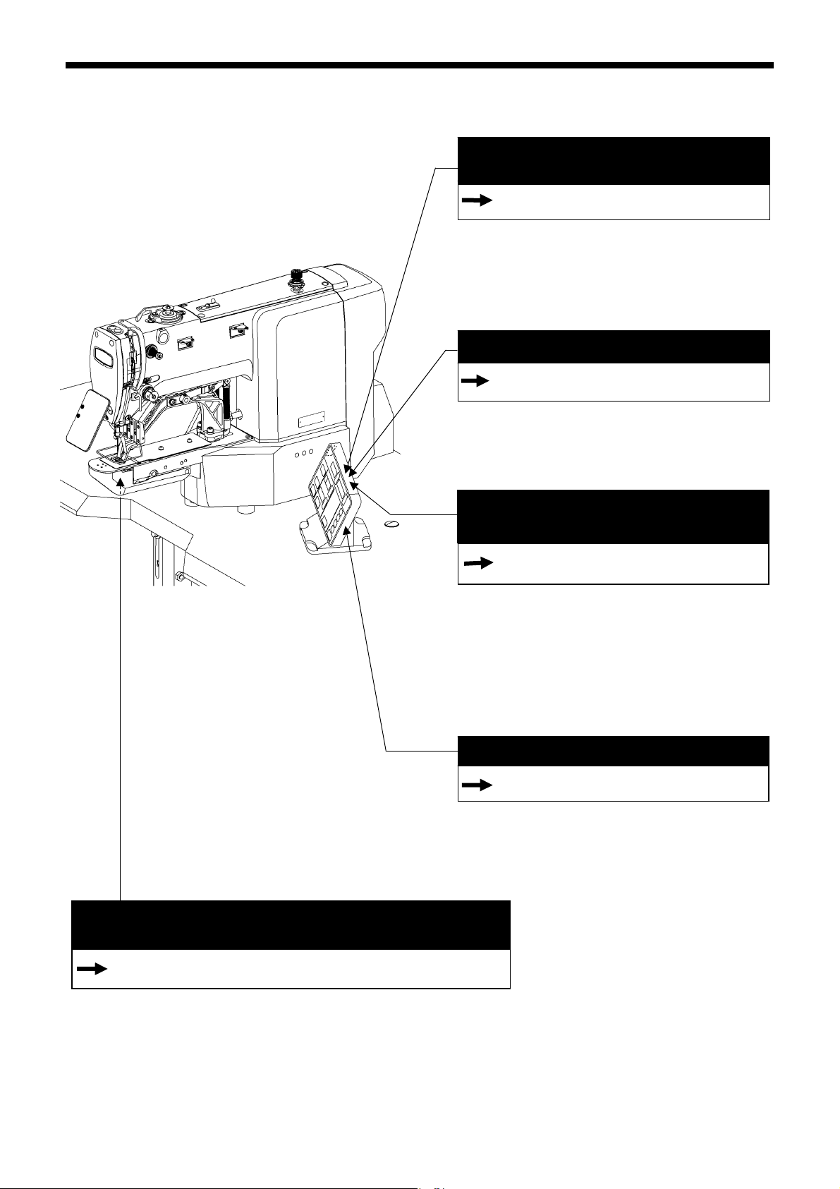
2. USEFUL FUNCTIONS FOR OPTIMUM SEWING
p
2. USEFUL FUNCTIONS FOR OPTIMUM SEWING
Original programs can be set easily using the
anel
Page 36
Patterns, X-scale, Y-scale, sewing speed, slow start
pattern and upper thread tension can be recorded
into programs.
When a program number is selected, the program
which has been set for that number can then be
sewn.
Copying programs can be done easily
Page 40
To create a program with parameters that are
almost exactly the same as those of another
program, you can copy the original program and
change just the parts which need to be changed.
Correcting the upper thread tension can be
done easily
<A. Basic method of use>
The changes made at this time will be reflected in
each program, so this is a useful way of changing
programs while checking actual sewing.
<B. Overall correction>
This function is useful if you would like to change
the tension values for all programs at once.
This is used to stop the thread from pulling out at the
sewing start, and at times when skipped stitches might
easily occur.
The starting-up speed at the sewing start can be
adjusted easily.
The thread nipper device prevents the thread from pulling out at the
sewing start (-03, -0K, -0F specifications).
Page 43
Slow start pattern setting is easy
Page 39
3186B
Page 31
This is used to stop the thread from pulling out at the sewing start, and at
times when skipped stitches might easily occur.
* The default setting for this memory switch is "OFF".
2
KE-430FX/KE-430FS, BE-438FX
Page 11
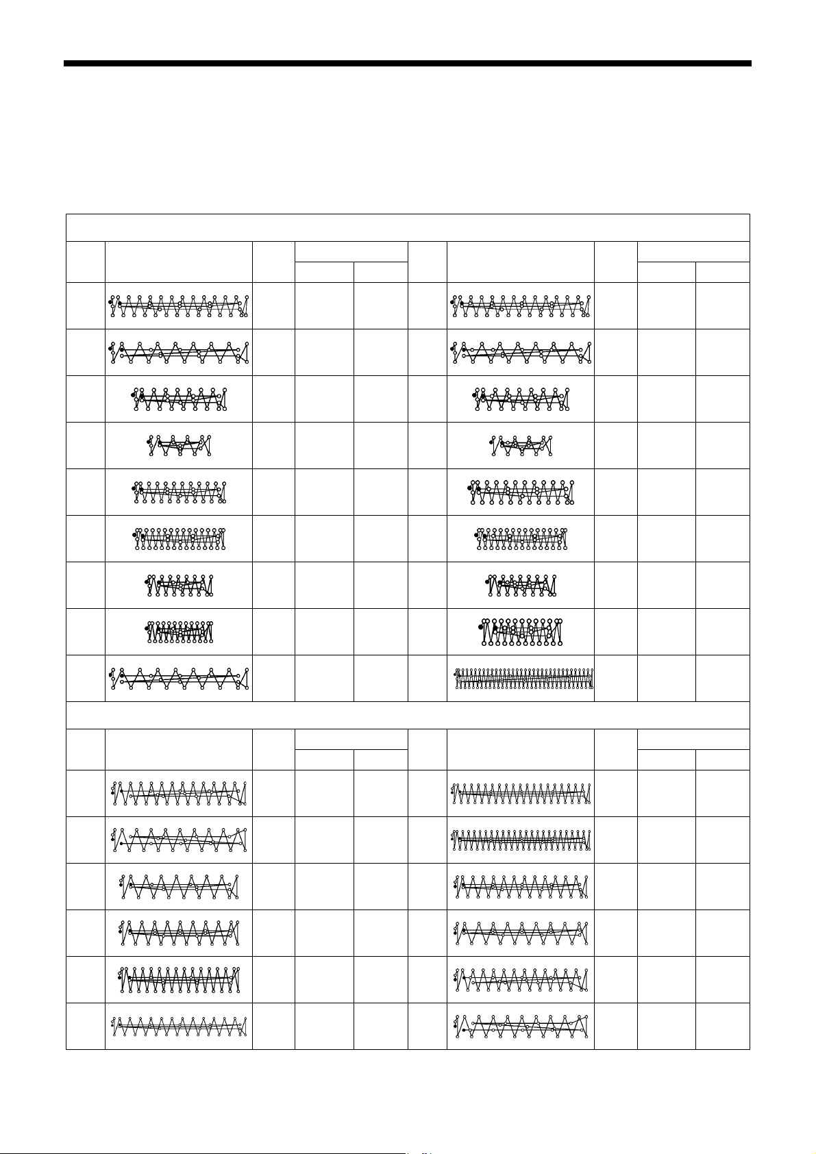
3. LIST OF SEWING PATTERNS
3. LIST OF SEWING PATTERNS
3-1. List of sewing patterns (KE-430FX・FS)
The sewing patterns shown below have been preset into the sewing machine and can be selected according to specifications.
(Any sewing pattern is available as long as it is within the work clamp and feed plate in size.)
Use the work clamp and feed plate that match the respective sewing pattern selected.
The sewing size is the length when the enlargement/reduction ratio is 100%.
For medium-weight materials (-03)
No. Pattern
1 42 16 2 65
4 31 16 2 66
5
8
13
15
20
21
No. of
stitches
Tacking size (mm)
Length
29 10 2 67
21 7 2 68
35 10 2 69
42 10 2 70
28 7 2 71
35 7 2 72
Width
No. Pattern
No. of
stitches
Tacking size (mm)
Length
43 16 2
32 16 2
30 10 2
22 7 2
36 10 2
43 10 2
29 7 2
36 7 2
Width
64 30 16 2 89
For heavy-weight materials (-05)
No. Pattern
2 42 20 3 18
3 35 20 3 19
6
14
16
17 42 24 3 79
No. of
stitches
Tacking size (mm)
Length
30 16 3 62
35 16 3 63
43 16 3 78
Width
No. Pattern
90 24 3
No. of
stitches
Tacking size (mm)
Length
56 24 3
64 24 3
42 20 3
35 20 3
43 20 3
36 20 3
Width
KE-430FX/KE-430FS, BE-438FX
3
Page 12
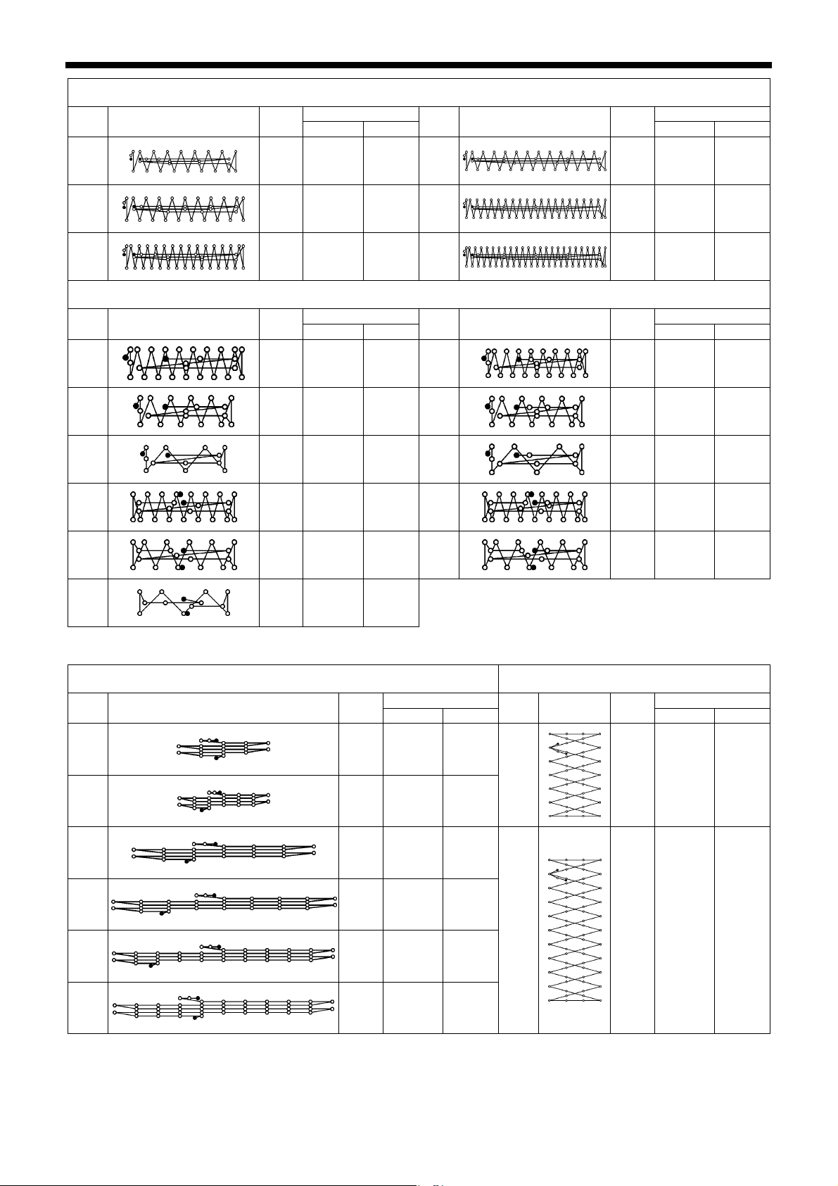
3. LIST OF SEWING PATTERNS
No. Pattern
No. of
stitches
For heavy-weight materials (-05)
Tacking size (mm)
Length
Width
No. Pattern
No. of
stitches
Tacking size (mm)
Length
Width
80
81
82
No. Pattern
7
9
22
31*
32*
31 16 3 83
36 16 3 84
44 16 3 85
For knitted materials (-0K) and foundation garments (-0F)
No. of
stitches
Tacking size (mm)
Length
Width
No. Pattern
28 8 2 73
21 7 2 74
14 7 2 75
28 8 2 76*
22 8 2 77*
43 24 3
57 24 3
65 24 3
No. of
stitches
Tacking size (mm)
Length
29 8 2
22 7 2
15 7 2
29 8 2
23 8 2
Width
33*
15 8 2
* The sewing start and sewing end are in the middle of the pattern.
Straight bar tacking Vertical zigzag stitching
No. Pattern
10
11
12
23
24
25
No. of
stitches
Tacking size (mm)
Length
21 10 0.3
28 10 0.3
28 20 0.3
35 25 0.3
42 25 0.3
45 25 0.3
Width
No. Pattern
44
45
No. of
stitches
Tacking size (mm)
Length
Width
46 9 15
70 9 25
4
KE-430FX/KE-430FS, BE-438FX
Page 13
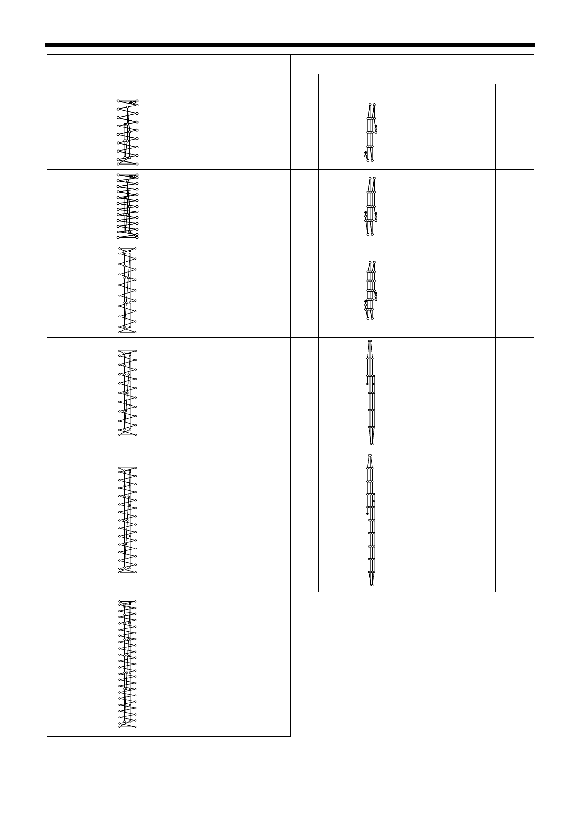
Vertical bar tacking Vertical straight bar tacking
No. Pattern
No. of
stitches
Tacking size (mm)
Length
Width
No. Pattern
3. LIST OF SEWING PATTERNS
No. of
stitches
Tacking size (mm)
Length
Width
26
27
40
41
28 3 10 28
35 3 10 29
32 3 16 30
19 0.3 10
21 0.3 10
28 0.3 10
36 3 16 46
27 0.3 20
42
43
44 3 20 47
44 0.3 25
68 3 24
KE-430FX/KE-430FS, BE-438FX
5
Page 14
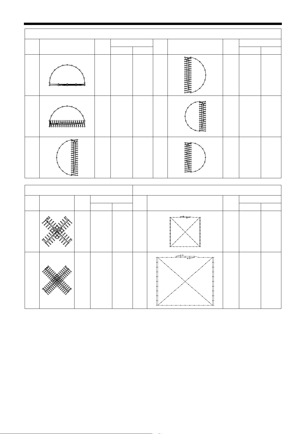
3. LIST OF SEWING PATTERNS
Crescent bar tacking
No. Pattern
34
35
36
Crossed stitching
No. of
stitches
Tacking size (mm)
Length
Width
No. Pattern
35 12 7 37
58 12 7 38
57 7 12 39
Crossed tacking
No. of
stitches
Tacking size (mm)
Length
Width
57 7 12
53 7 10
53 7 10
No. Pattern
48
49
No. of
stitches
Tacking size (mm)
Length
Width
70 10 10 50
93 9.6 9.6 51
No. Pattern
No. of
stitches
Tacking size (mm)
Length
Width
84 16 16
105 30 26
6
KE-430FX/KE-430FS, BE-438FX
Page 15
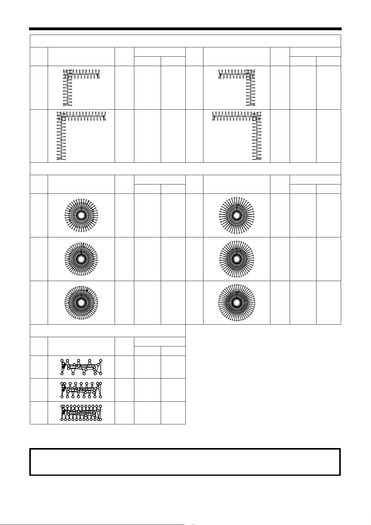
3. LIST OF SEWING PATTERNS
L-pattern tacking
No. Pattern
52
54
No. Pattern
56
No. of
stitches
Tacking size (mm)
Length
Width
No. Pattern
60 11.3 11.2 53
78 15.3 15.2 55
Circular stitching
No. of
stitches
Tacking size (mm)
Length
Width
No. Pattern
106 9 9 59
No. of
stitches
Tacking size (mm)
Length
Width
60 11.3 11 .2
78 15.3 15.2
No. of
stitches
Tacking size (mm)
Length
Width
104 10 10
57
58
116 9 9 60
127 9 9 61
114 10 10
124 10 10
For eyelet buttonhole
No. Pattern
86
No. of
stitches
Tacking size (mm)
Length
Width
21 6 2
87
28 6 2
88
35 6 2
If you want to sew a sewing pattern other than standard sewing patterns, you can create your original pattern using the
PS-300B. Consult with your local Brother sales office for details.
Note when creating additional sewing patterns
When sewing data with a small number of stitches (15 stitches or less) is sewn repeatedly (short cycle operation), the
upper shaft motor may overheat and the “E150” error code may be generated.
KE-430FX/KE-430FS, BE-438FX
7
Page 16
3. LIST OF SEWING PATTERNS
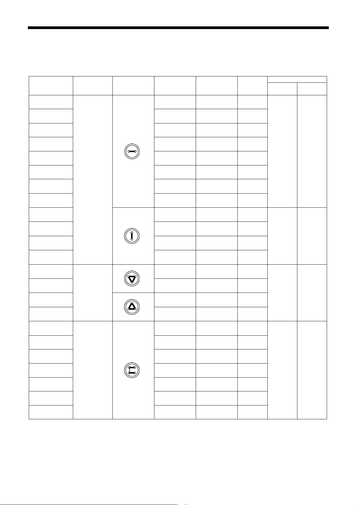
3-2. List of sewing patterns (BE-438FX)
The sewing patterns shown below have been preset into the sewing machine. Any sewing pattern can be selected as long as
the needle will drop down into the holes of the buttons.
When sewing patterns that do not have crossover stitches, the thread is trimmed after sewing of one side is completed, and
then the other side is sewn.
No.
1
No. of holes
in button
Pattern
No. of
threads
6 ― 12
No. of
crossover
stitches
No. of
stitches
Sewing size (mm)
X Y
*1
54
2 8 ― 14
*1
55
3 10
4 12 ― 18
*2
5
*2
6
*1
56
*3
7
*3
23
*3
8
*3
9
*3
24
*3
25
*3
26
*1
57
2
3
6 ― 12
8 ― 14
3.4 0
―
16 ― 22
20 ― 26
6 ― 11
6 ― 12
10 ― 16
12 ― 18
5-5-5 ― 21
7-7-7 ― 27
5-5-5 ― 21
7-7-7 ― 27
6-6 1 18
16
0 3.4
2.6 2.4
10 6-6 1 19
*1
58
11 8-8 1 23
12 8-8 3 25
13 10-10 1 27
27 12-12 1 31
*1 Use for buttons with small holes.
*2 Check that the diameter of the holes in the buttons is 2 mm or greater before using the programs.
*3 Do not use the button lifter spring.
8
4
KE-430FX/KE-430FS, BE-438FX
8-8 1 22
3.4 3.4
Page 17
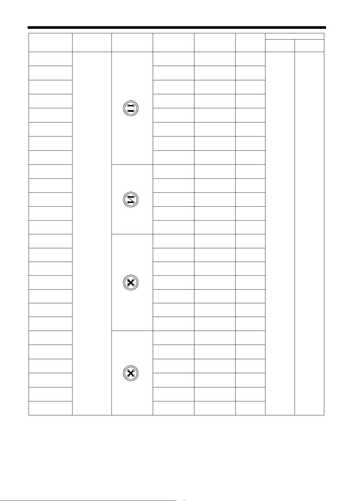
3. LIST OF SEWING PATTERNS
No.
14
36
28
37
15
38
29
39
59
No. of holes
*4
*5
*4
*5
*4
*5
*4
*5
*1
in button
Pattern
No. of
threads
No. of
crossover
stitches
No. of
stitches
6-6 0 24
6-6 0 24
8-8 0 28
8-8 0 28
10-10 0 32
10-10 0 32
12-12 0 36
12-12 0 36
6-5 1 17
Sewing size (mm)
X Y
16 6-5 1 18
60
*1
8-7 1 21
17 8-7 1 22
30 10-9 1 26
61
*1
4
6-6 1 18
3.4 3.4
18 6-6 1 19
*1
62
8-8 1 22
19 8-8 1 23
*1
63
10-10 1 26
31 10-10 1 27
45 12-12 1 31
20
40
32
41
33
42
*4
*5
*4
*5
*4
*5
6-6 0 24
6-6 0 24
8-8 0 28
8-8 0 28
10-10 0 32
10-10 0 32
*1 Use for buttons with small holes.
*4 When sewing of one side is completed, the button clamp rises and the thread is trimmed. To finish sewing, press the foot
switch until sewing of the other side starts, or press the foot switch again after sewing of the other side is completed.
*5 When sewing of one side is completed, the thread will be trimmed without the button clamp rising, and then the other
side will be sewn.
KE-430FX/KE-430FS, BE-438FX
9
Page 18
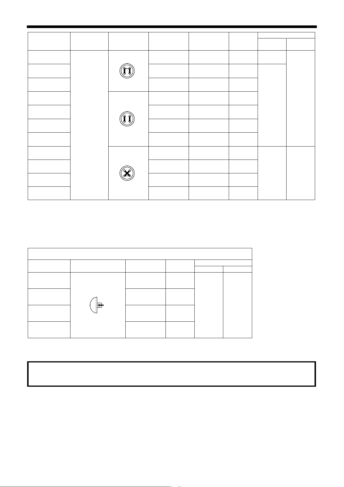
3. LIST OF SEWING PATTERNS
No.
No. of holes
in button
*1
64
*3
21
*3
34
*3*4
22
*3*5
43
*3*4
35
4
*3*5
44
Pattern
No. of
threads
No. of
crossover
stitches
No. of
stitches
Sewing size (mm)
X Y
6-6 1 18 3.4
6-6 1 19
10-10 1 27
6-6 0 24
3.4
2.4
6-6 0 24
10-10 0 32
10-10 0 32
46
6-7 1 19
47 8-9 1 23
3.4 3.4
48 10-11 1 27
49 12-13 1 31
*1 Use for buttons with small holes.
*3 Do not use the button lifter spring.
*4 When sewing of one side is completed, the button clamp rises and the thread is trimmed. To finish sewing, press the foot
switch until sewing of the other side starts, or press the foot switch again after sewing of the other side is completed.
*5 When sewing of one side is completed, the thread will be trimmed without the button clamp rising, and then the other
side will be sewn.
For shank button
No. Pattern No. of threads
50
6 12
No. of
stitches
Sewing size (mm)
X Y
51 8 14
3.4 0
52 10 16
53 12 18
Note when creating additional sewing patterns
When sewing data with a small number of stitches (15 stitches or less) is sewn repeatedly (short cycle operation), the
upper shaft motor may overheat and the “E150” error code may be generated.
10
KE-430FX/KE-430FS, BE-438FX
Page 19
4. INSTALLATION
4. INSTALLATION
CAUTION
Machine installation should only be carried out by a
qualified technician.
Contact your Brother dealer or a qualified electrician
for any electrical work that may need to be done.
The sewing machine head weighs approximately 57
kg. The installation should be carried out by two or
more people.
Do not connect the power cord until installation is
complete, otherwise the machine may operate if the
foot switch is depressed by mistake, which could
result in injury.
Hold the machine head with both hands when tilting it
back or returning it to its original position.
Furthermore, after tilting back the machine head, do
not push the face plate side or the pulley side from
above, as this could cause the machine head to
topple over, which may result in personal injury or
damage to the machine
.
All cords should be secured at least 25 mm away
from any moving parts. Furthermore, do not
excessively bend the cable or secure it too firmly
staples, otherwise there is the danger that fire or
electric shocks could occur.
Be sure to connect the ground. If the ground
connection is not secure, you run the risk of receiving
a serious electric shock, and problems with correct
operation may also occur.
Install the safety covers to the machine head and
motor.
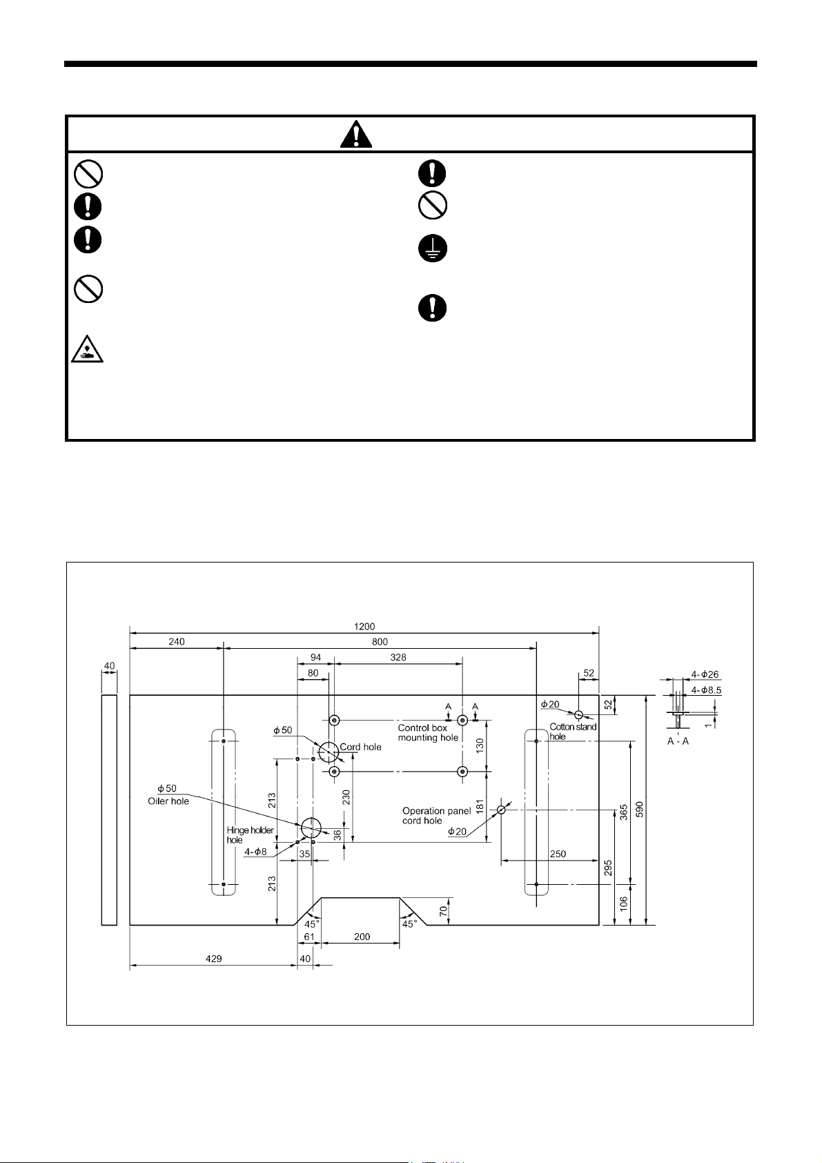
4-1. Table processing diagram
• The thickness of the table should be at least 40 mm, and it should be strong enough to bear the weight and vibration of the
sewing machine.
• Check that the control box is at least 10 mm away from the leg. If the control box and the leg are too close together, it may
result in incorrect sewing machine operation.
2453B
11KE-430FX/KE-430FS, BE-438FX
Page 20
4. INSTALLATION
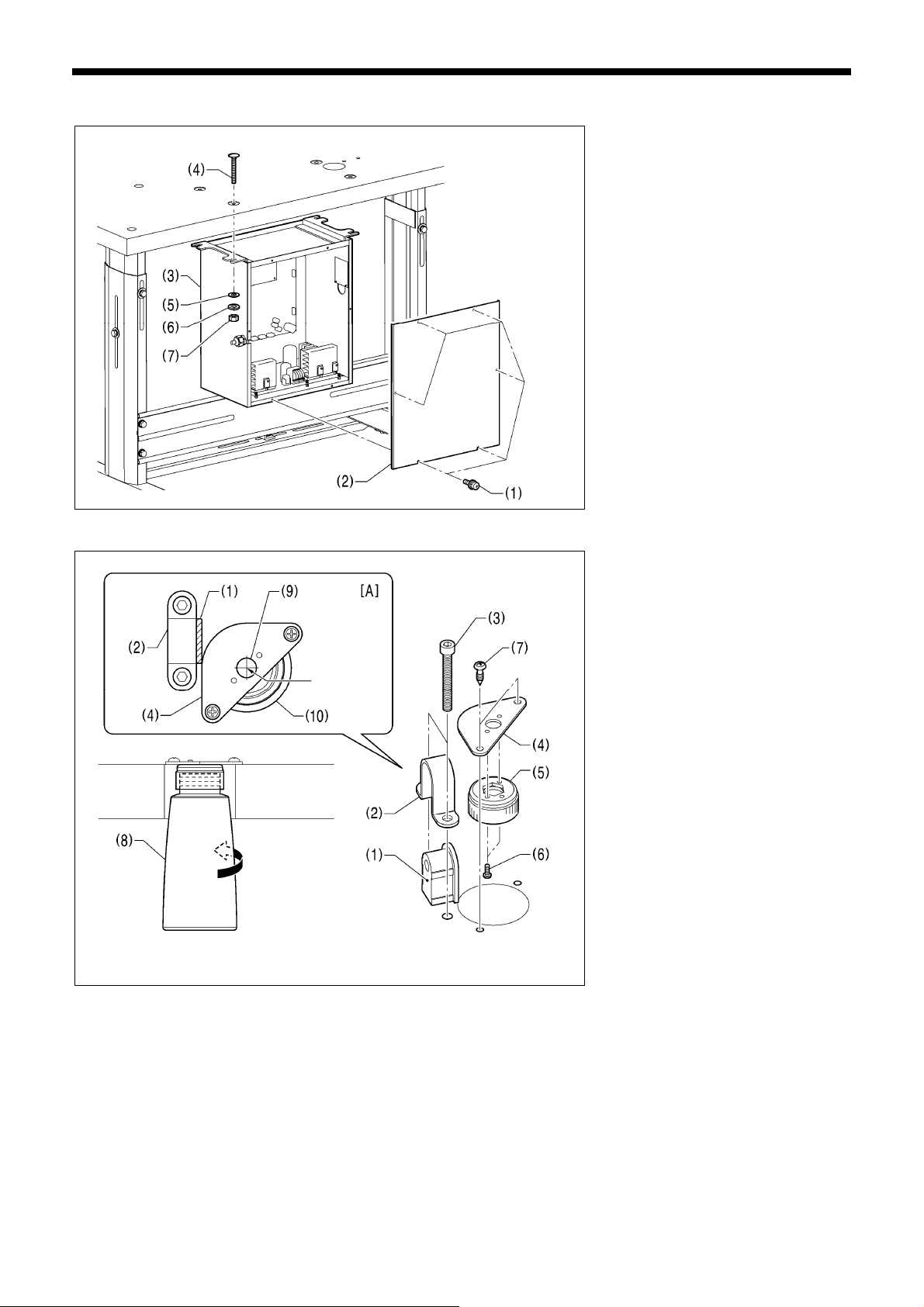
4-2. Installing the control box
2280B
Remove the six screws (1), and then
remove the control box cover (2).
(3) Control box
(4) Bolts [4 pcs]
(5) Plain washers [4 pcs]
(6) Spring washers [4 pcs]
(7) Nuts [4 pcs]
4-3. Installing the oiler
Center
Before installing the oiler, provisionally
install the rubber cushion (1) and the
hinge holder (2) to the table with the two
bolts (3).
(4) Dust oiler setting plate
(5) Dust oiler
(6) Screws [2 pcs]
(7) Wood screws [2 pcs]
(8) Oiler
* Install the dust oiler setting plate (4) so
that the hole (9) in the dust oiler setting
plate (4) is in the center of the hole (10)
in the table for installing the oiler (8) as
shown in figure [A].
NOTE:
• Make sure that the dust oiler setting
plate (4) does not interfere with the
hinge holder (2).
2281B
12 KE-430FX/KE-430FS, BE-438FX
Page 21
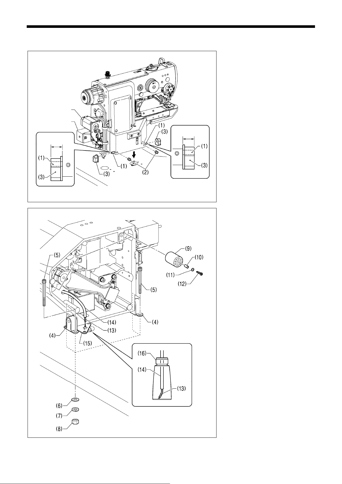
4-4. Installing the machine head
Pulse motor
Solenoid
Approx. 20mm
Approx. 20mm
3166B
4. INSTALLATION
(1) Pins [2 pcs]
(2) Set screws [2 pcs]
(3) Rubber cushion assembly [2 pcs]
Place the machine head gently on top of
the table.
NOTE:
• Be careful not to clamp any cords
between the machine head and the
table.
• When holding the machine head, do
not hold it by the pulse motor or the
solenoid, otherwise it may damage the
pulse motor or solenoid.
(4) Hinge holders [2 pcs]
(5) Bolts [4 pcs]
(6) Plain washers [4 pcs]
(7) Spring washers [4 pcs]
(8) Nuts [4 pcs]
(9) Rubber cushions [3 pcs]
(10) Collar [3 pcs]
(11) Plain washers [3 pcs]
(12) Screws [3 pcs]
(13) Felt
(14) Oil tube
Pass the felt (13) and the oil tube (14)
through the hole in the dust oiler setting
plate (15) into the oiler (16).
3167B
KE-430FX/KE-430FS, BE-438FX
13
Page 22
4. INSTALLATION
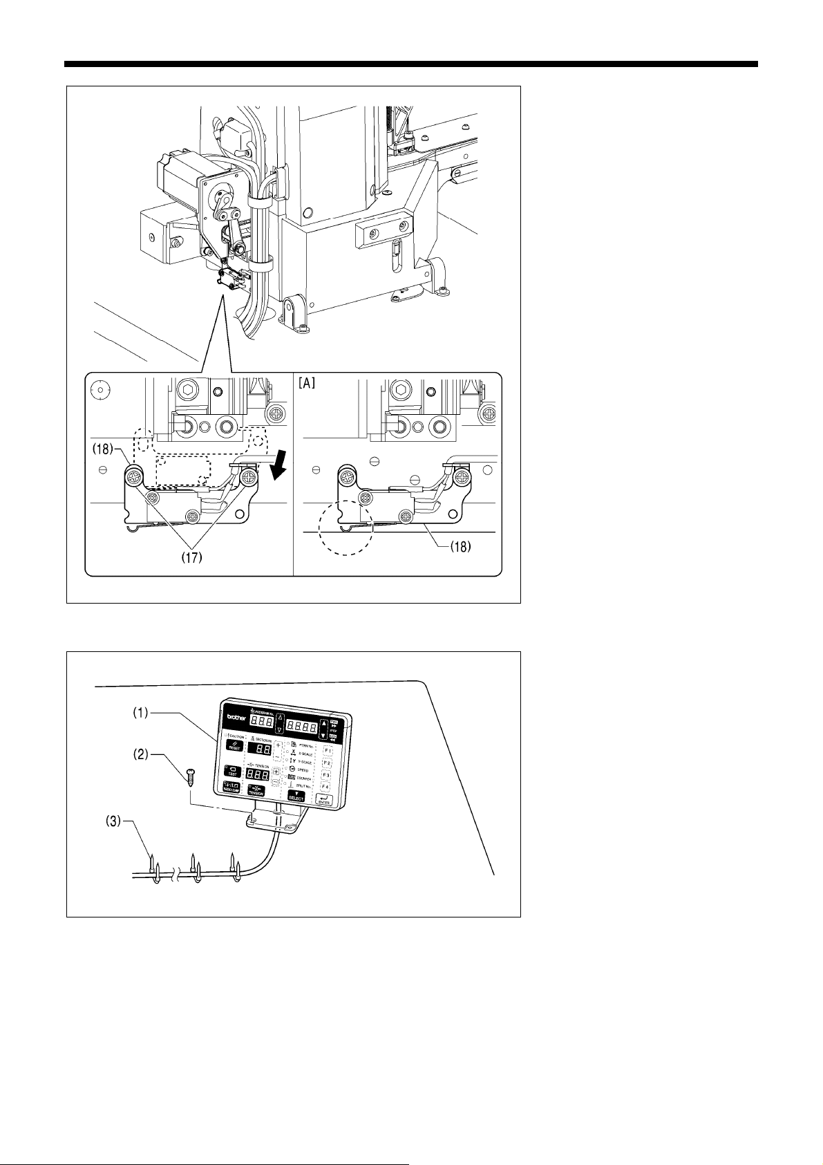
2284B
2285B
1. Remove the two screws (17), and
then temporarily remove the machine
head switch (18).
2. Use the two screws (17) which were
removed to install the machine head
switch (18) in the position shown in
the illustration.
3. Check that the machine head switch
as turned on as shown in figure [A].
* If the machine head switch is not
turned on, adjust the installation
position while referring to “4-14.
Checking the machine head switch”.
4-5. Installing the operation panel
2286B
(1) Operation panel
(2) Wood screws [4 pcs]
* Pass the panel cord through the
hole in the table, and then insert it
into the control box through the
hole in the side of the control box.
(3) Staples [3 pcs]
14 KE-430FX/KE-430FS, BE-438FX
Page 23
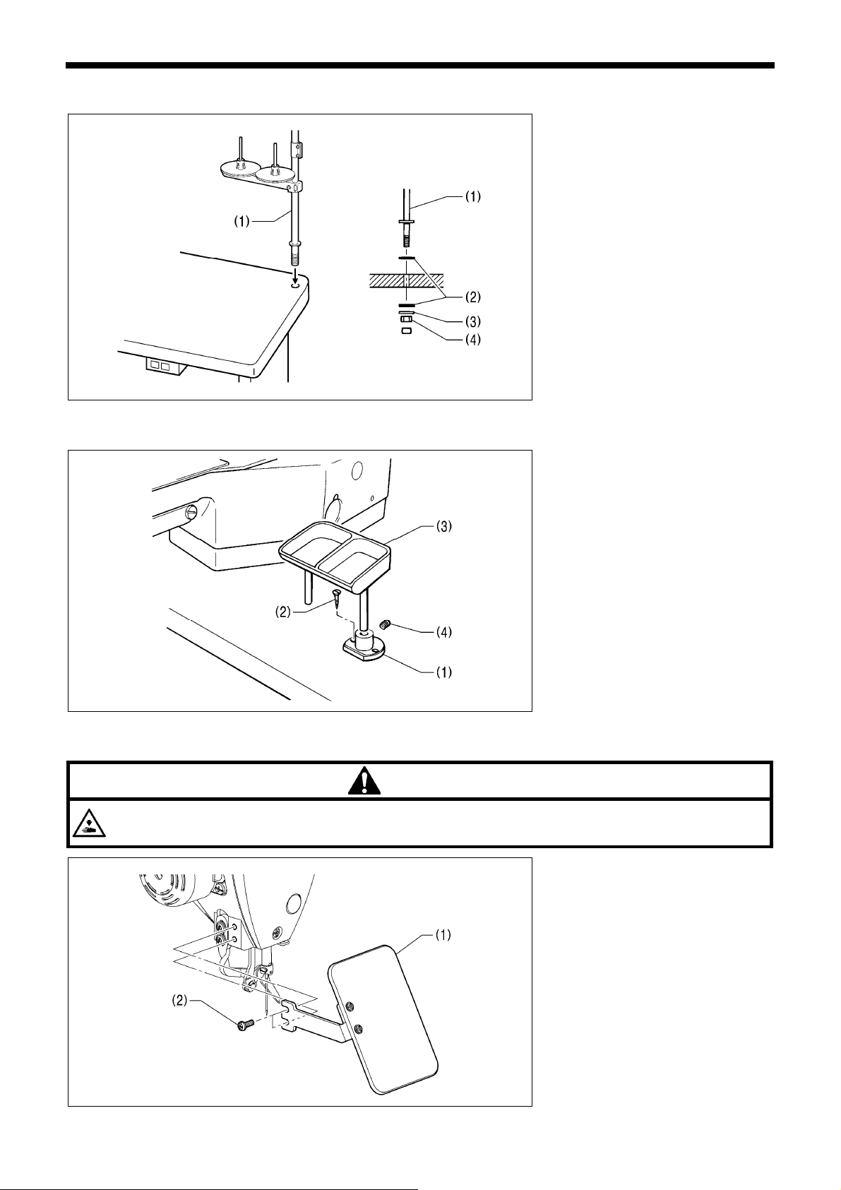
4-6. Installing the cotton stand
4-7. Installing the button tray (BE-438FX)
3636M
4410Q
4. INSTALLATION
(1) Cotton stand
NOTE:
Securely tighten the nut (4) so that the
two rubber cushions (2) and the
washer (3) are securely clamped and
so that the cotton stand (1) does not
move.
Install the button tray at a place
convenient for operation.
(1) Button tray holder
(2) Wood screws [2 pcs]
(3) Button tray
(4) Set screw
4-8. Installing the eye guard
Attach all safety devices before using the sewing machine.
If the machine is used without these devices attached, injury may result.
CAUTION
(1) Eye guard assembly
(2) Screws [2 pcs]
2287B
15KE-430FX/KE-430FS, BE-438FX
Page 24
4. INSTALLATION
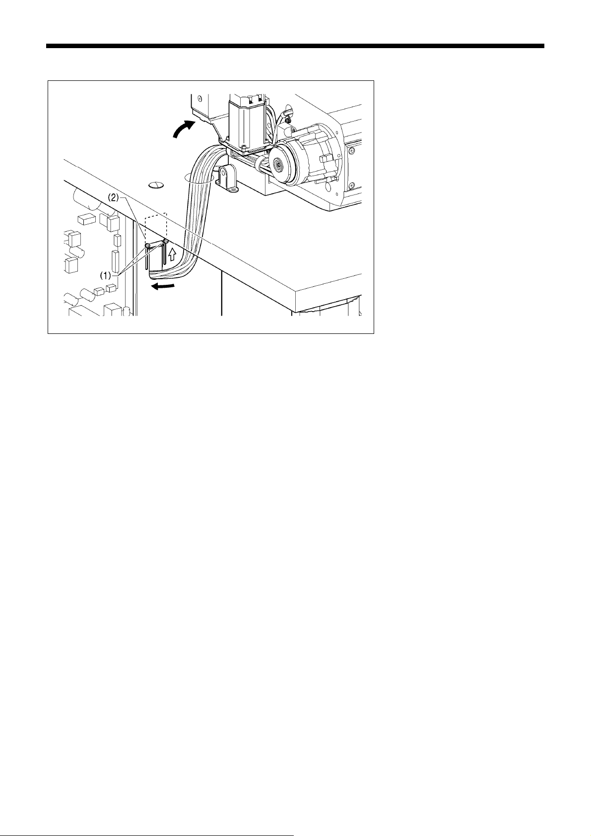
4-9. Connecting the cords
2288B
1. Gently tilt back the machine head.
2. Pass the cord bundle through the hole
in the work table.
3. Loosen the two screws (1), and then
open the cord presser plate (2) in the
direction of the white arrow and pass
the cord bundle through the opening.
4. Securely connect the connectors as
indicated in the table below.
(Refer to following page.)
NOTE:
• Check that the connector is facing the
correct way, and then insert it firmly
until it locks into place.
• Secure the cables with cable ties and
cord clamps, while being careful not to
pull on the connector.
(Continued on next page.)
16 KE-430FX/KE-430FS, BE-438FX
Page 25
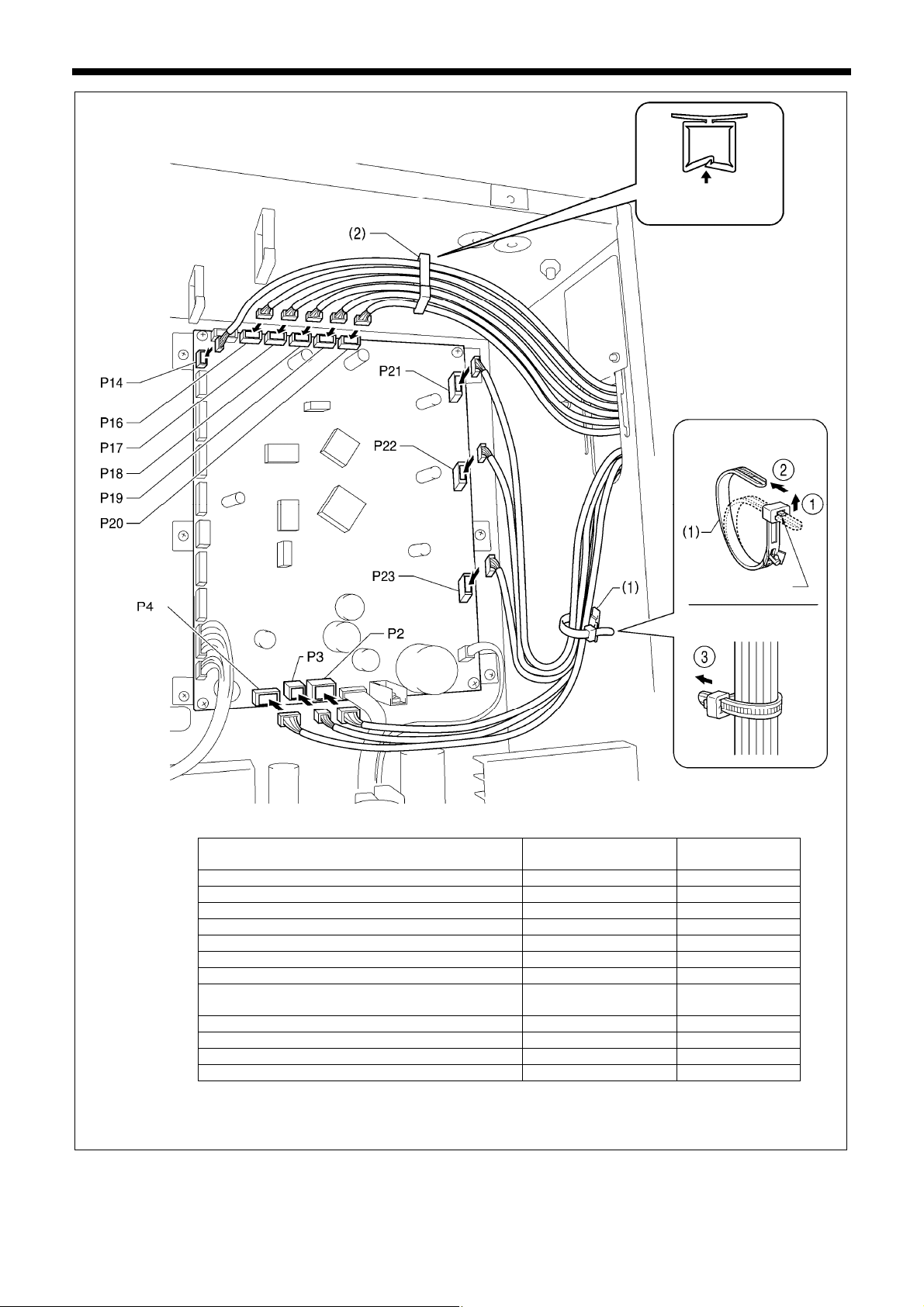
4. INSTALLATION
k
X
Y
k
< Main P. C. board >
Lock the cord
clamp securely.
<Removal>
<Securing>
2289B
X pulse motor encoder [5-pin] White P17 (X-ENC) (2)
Y pulse motor encoder [5-pin] Blue P18 (Y-ENC) (2)
Work clamp pulse motor encoder 5-pin Blac
Thread nipper pulse motor encoder 5-pin Red P20 (T-ENC) (2)
Machine head switch [3-pin] P14 (HEAD-SW) (2)
Machine head memory [6-pin] P16 (HEAD-M) (2)
Thread trimmer solenoid [6-pin] P2 (SOL1) (1)
Digital tension 4-pin
/Tension release solenoid 4 -pin
Thread clamp pulse motor [4-pin] Red P4 (TPM) (1)
pulse motor [4-pin] White P21 (XPM) (1)
pulse motor [4-pin] Blue P22 (YPM) (1)
Work clamp pulse motor [4-pin] Blac
Connectors
Connection location on
main P. C. board
Cord clamps
P19 (P-ENC) (2)
P3 (SOL2) (1)
P23 (PPM) (1)
NOTE: Route the X, Y and work clamp pulse motor harnesses so that they do not touch the power supply P.C. board.
Press
the tab.
(Continued on next page.)
17KE-430FX/KE-430FS, BE-438FX
Page 26
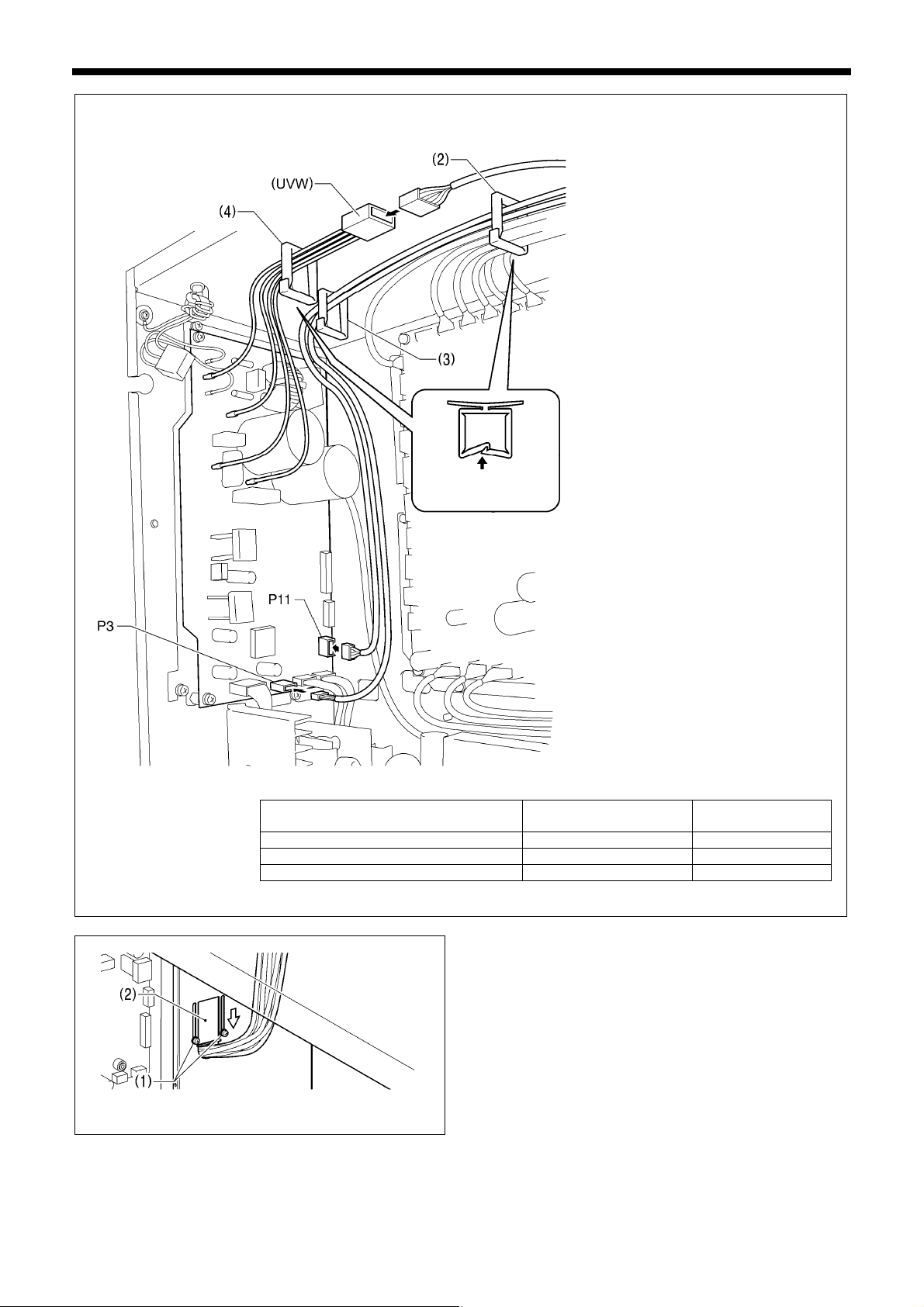
4. INSTALLATION
/
< Motor P. C. board >
2290B
Lock the cord clamps
(2) and (4) securely.
Connectors
Connection location on
motor P. C. board
Cord clamps
cable ties
Upper shaft motor [4-pin] (UVW) (4)
Synchronizer [10-pin] P11(SYNC) (2) (3)
Operation panel [4-pin] P3 (PANEL) (2) (3)
5. Close the cord presser plate (2) in the direction of the white
arrow, and secure it by tightening the two screws (1).
NOTE:
Close the cord presser plate (2) securely so that no
foreign objects, insects or small animals can get inside the
control box.
6. Check that the cords do not get pulled, and then gently return
the machine head to its original position.
2291B
18 KE-430FX/KE-430FS, BE-438FX
Page 27
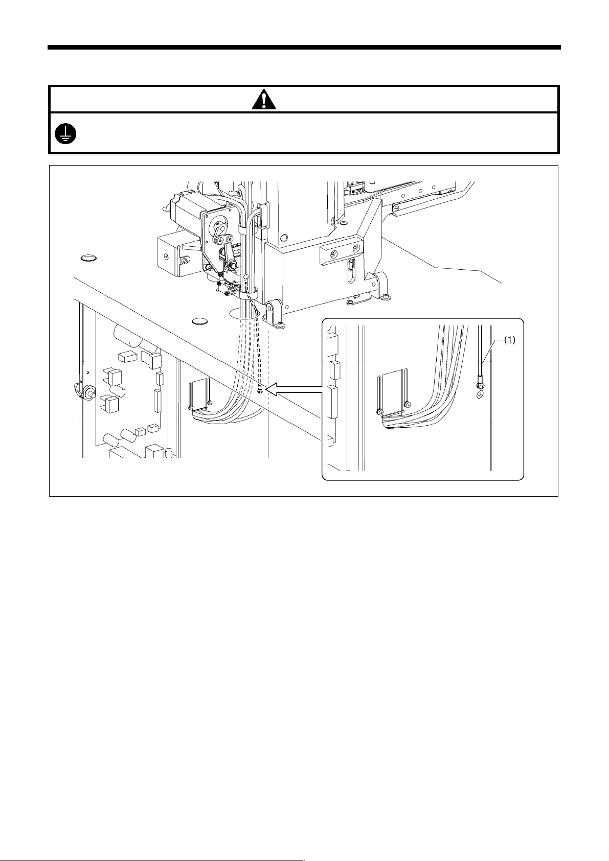
4-10. Connecting the ground wire
CAUTION
Be sure to connect the ground. If the ground connection is not secure, you run the risk of receiving a serious electric
shock, and problems with correct operation may also occur.
(1) Ground wire from the machine head (Ground mark position)
* The recommended tightening torque for the ground screws is 1.0±0.1 N・m.
NOTE:
Make sure that the ground connections are secure in order to ensure safety.
4. INSTALLATION
2292B
19KE-430FX/KE-430FS, BE-438FX
Page 28
4. INSTALLATION
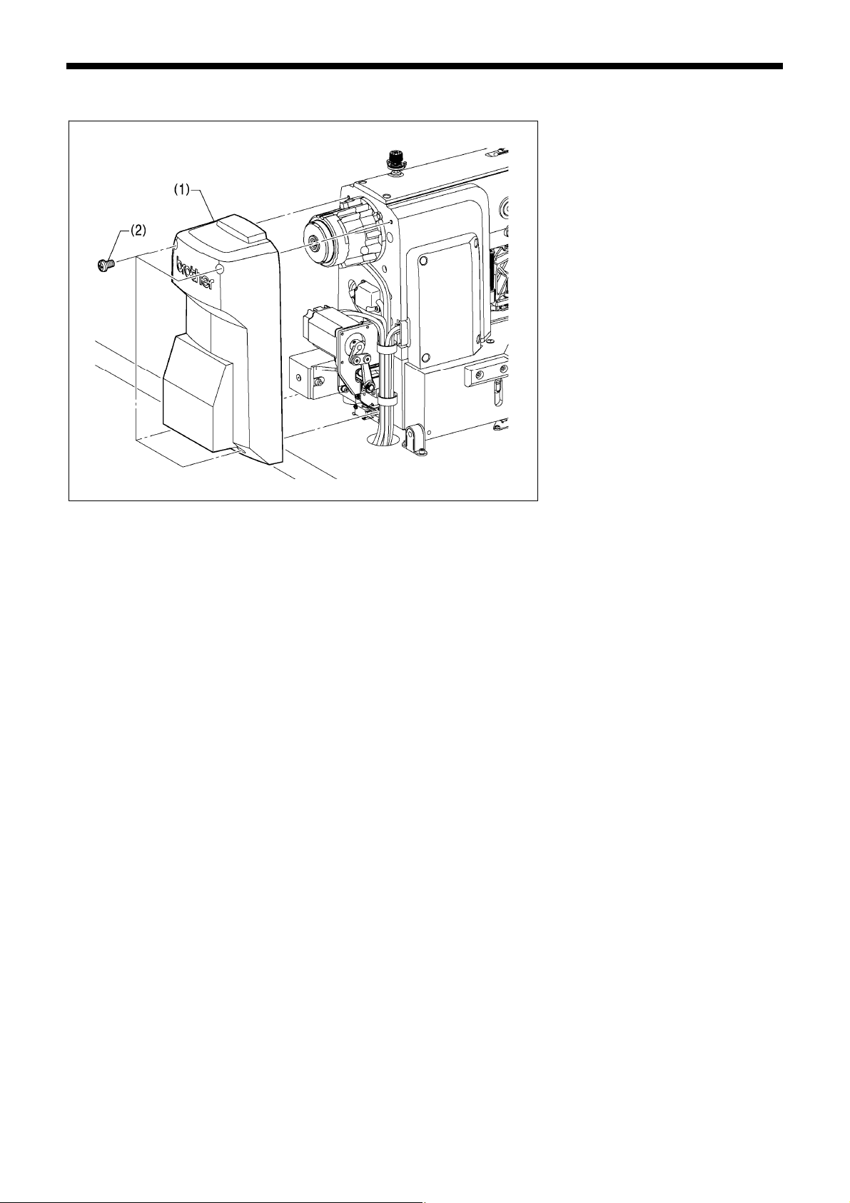
4-11. Installing the rear cover
(1) Rear cover
(2) Screws [4 pcs]
NOTE:
Be careful not to clamp the cords when
installing the rear cover (1).
3168B
20 KE-430FX/KE-430FS, BE-438FX
Page 29
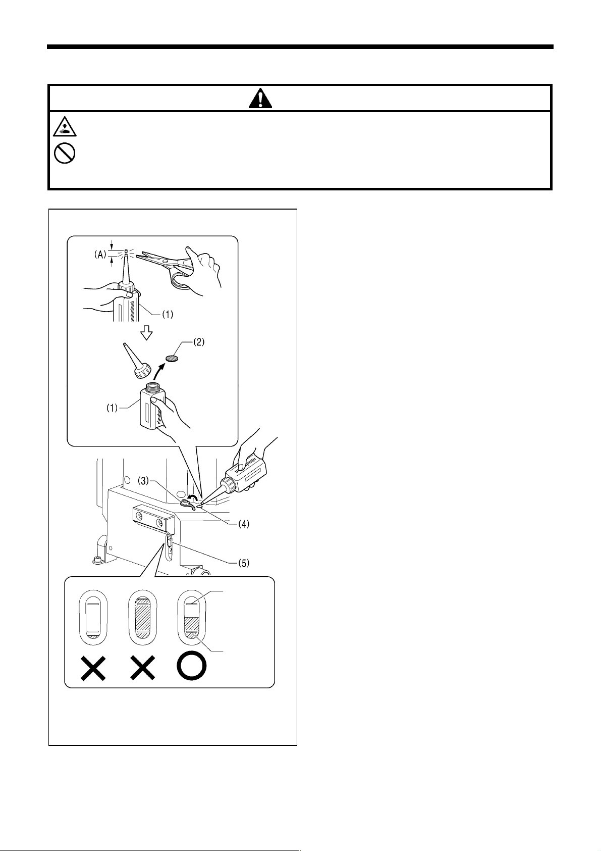
4-12. Lubrication
Do not connect the power cord until lubrication has been completed, otherwise the machine may operate if the foot switch
is depressed by mistake, which could result in injury.
Be sure to wear protective goggles and gloves when handling the lubricating oil and grease, so that they do not get into
your eyes or onto your skin, otherwise inflammation can result.
Furthermore, do not drink the oil or eat the grease under any circumstances, as they can cause vomiting and diarrhoea.
Keep the oil out of the reach of children.
CAUTION
・ The sewing machine should always be lubricated and the oil
supply replenished before it is used for the first time, and also
after long periods of non-use.
・ Use only the lubricating oil <Nippon Oil Corporation Sewing
Lube 10N; VG10> specified by Brother.
* If this type of lubricating oil is difficult to obtain, the recommended oil
to use is <Exxon Mobil Essotex SM10; VG10>.
1. Hold the base of the nozzle of the accessory oil tank (1), and
use scissors to cut about half-way along the straight section
(A) of the nozzle.
2. Loosen and remove the nozzle, and then remove the seal
(2).
3. Tighten the nozzle.
4. Open the oil feeding pocket cover (3).
5. Insert the nozzle of the oil tank (1) deeply into the oil feeding
pocket (4), and then add lubricating oil.
6. Check that the oil level is between the upper reference line
and the lower reference line in the oil gauge window (5).
NOTE:
• When the oil level drops below the lower reference line in the
oil gauge window, be sure to add more oil. If the oil level drops
below the lower reference line, problems with operation of the
sewing machine such as seizing may occur.
• Do not add oil so that the oil level goes above the upper
reference line, otherwise the oil may spill out when the
machine head is tilted back
Upper
reference
line
Lower
reference
line
4. INSTALLATION
(Continued on next page.)
2294B
KE-430FX/KE-430FS, BE-438FX
21
Page 30
4. INSTALLATION
B
s
2381B
2454B
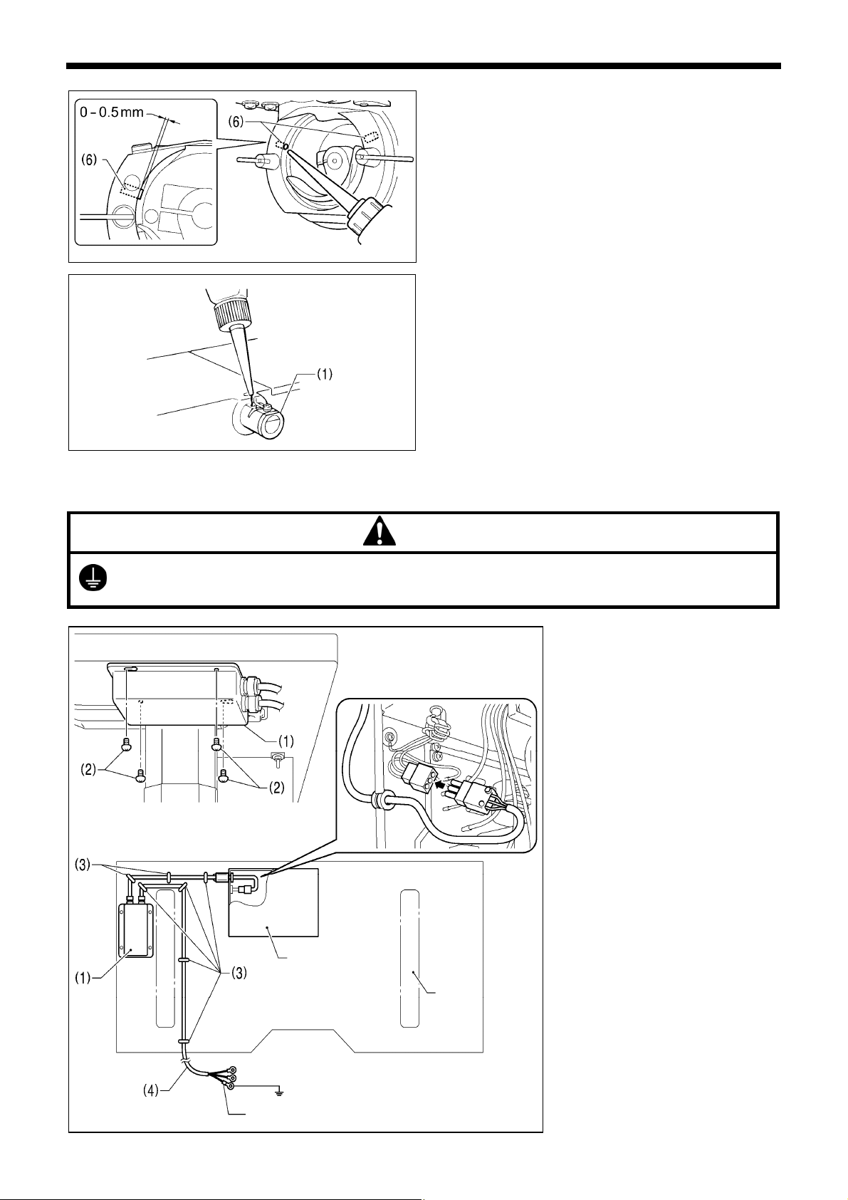
7. Pour oil in through the two holes of the shuttle race base
assembly so that the felt (6) is lightly moistened.
NOTE:
• The two pieces of felt (6) should normally project by 0 to 0.5
mm from the hook race. Be careful not to push in the felt (6)
when lubricating.
• If there is no more oil on the felt (6) of the shuttle race base
assembly, problems with sewing may result.
< When using the needle cooler (option)>
If using the needle cooler (option) (1), fill it with silicon oil.
4-13. Connecting the power cord
CAUTION
< Seen from underneath table >
e sure to connect the ground. If the ground connection is not secure, you run a high risk of receiving a serious electric
hock, and problems with correct operation may also occur.
Control box
Leg
Connect cords that match the voltage
specifications.
< EU specifications>
(1) Filter box
(2) Screws [4 pcs]
(3) Staples [7 pcs]
(4) Power cord
1. Attach an appropriate plug to the
power cord (4). (The green and yellow
wire is the ground wire.)
2. Insert the power plug into a
properly-grounded electrical outlet.
NOTE:
• Take care when tapping in the staples
(3) to make sure that they do not pierce
the cords.
• Do not use extension cords, otherwise
machine operation problems may
result.
Green and yellow wire (ground wire)
22 KE-430FX/KE-430FS, BE-438FX
2353B
Page 31
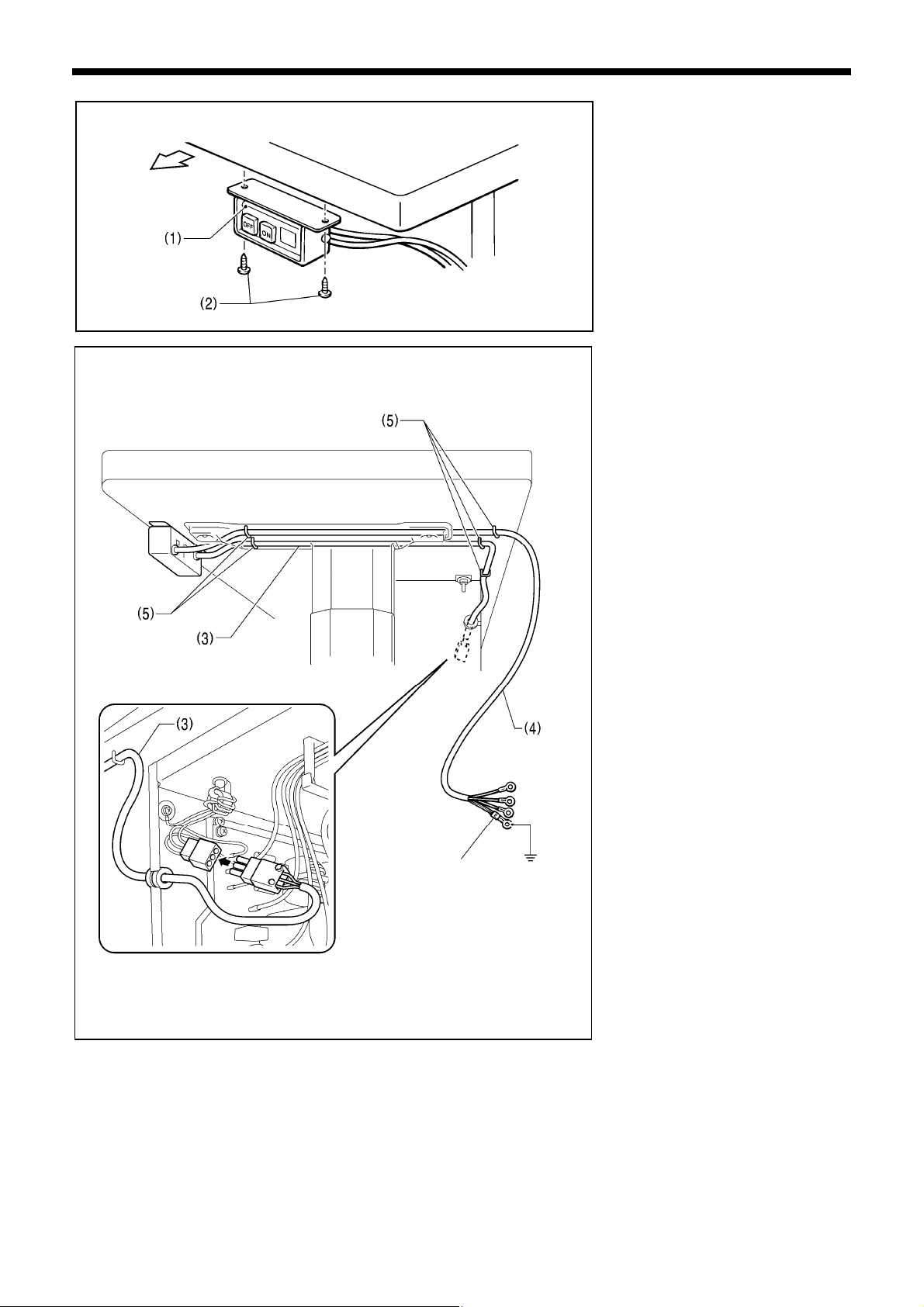
Operator
Green and yellow wire
(ground wire)
4145M
2347B
4. INSTALLATION
<200 V system >
(1) Power switch
(2) Screws [2 pcs]
(3) 3-pin power supply connector
(4) Power cord
(5) Staples [5 pcs]
1. Attach an appropriate plug to the
power cord (4). (The green and yellow
wire is the ground wire.)
2. Insert the power plug into a
properly-grounded electrical outlet.
NOTE:
• Take care when tapping in the staples
(5) to make sure that they do not pierce
the cords.
• Do not use extension cords, otherwise
machine operation problems may
result.
3. Use the six screws to tighten the cover
of the control box. Check that none of
the cords are being clamped by the
cover at this time.
KE-430FX/KE-430FS, BE-438FX
23
Page 32
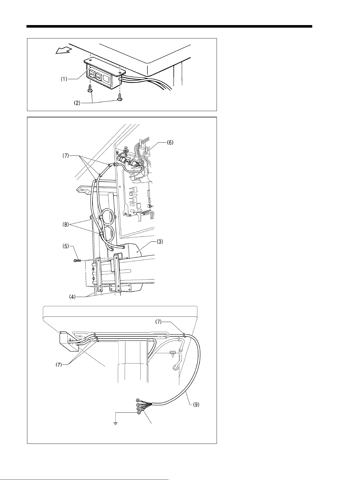
4. INSTALLATION
B
M
Operator
Green and yellow wire
(ground wire)
<100 V / 400 V system >
(1) Power switch
(2) Screws [2 pcs]
4145
2348
(3) Transformer box
(4) Transformer box plates [2 pcs]
(5) Screw [with washer]
(6) 3-pin power supply connector
(7) Staples [6 pcs]
(8) Cord clamps [2 pcs]
(9) Power cord
1. Attach an appropriate plug to the
power cord (9). (The green and yellow
wire is the ground wire.)
2. Insert the power plug into a
properly-grounded AC power supply.
* The inside of the control box uses
single-phase power.
NOTE:
• If the ground connection is not secure,
electric shocks, operating errors or
damage to electronic components such
as P.C. boards may occur.
• Take care when tapping in the staples
(7) to make sure that they do not pierce
the cords.
• Do not use extension cords, otherwise
machine operation problems may
result.
3. Use the six screws to tighten the cover
of the control box. Check that none of
the cords are being clamped by the
cover at this time.
2351B
24 KE-430FX/KE-430FS, BE-438FX
Page 33
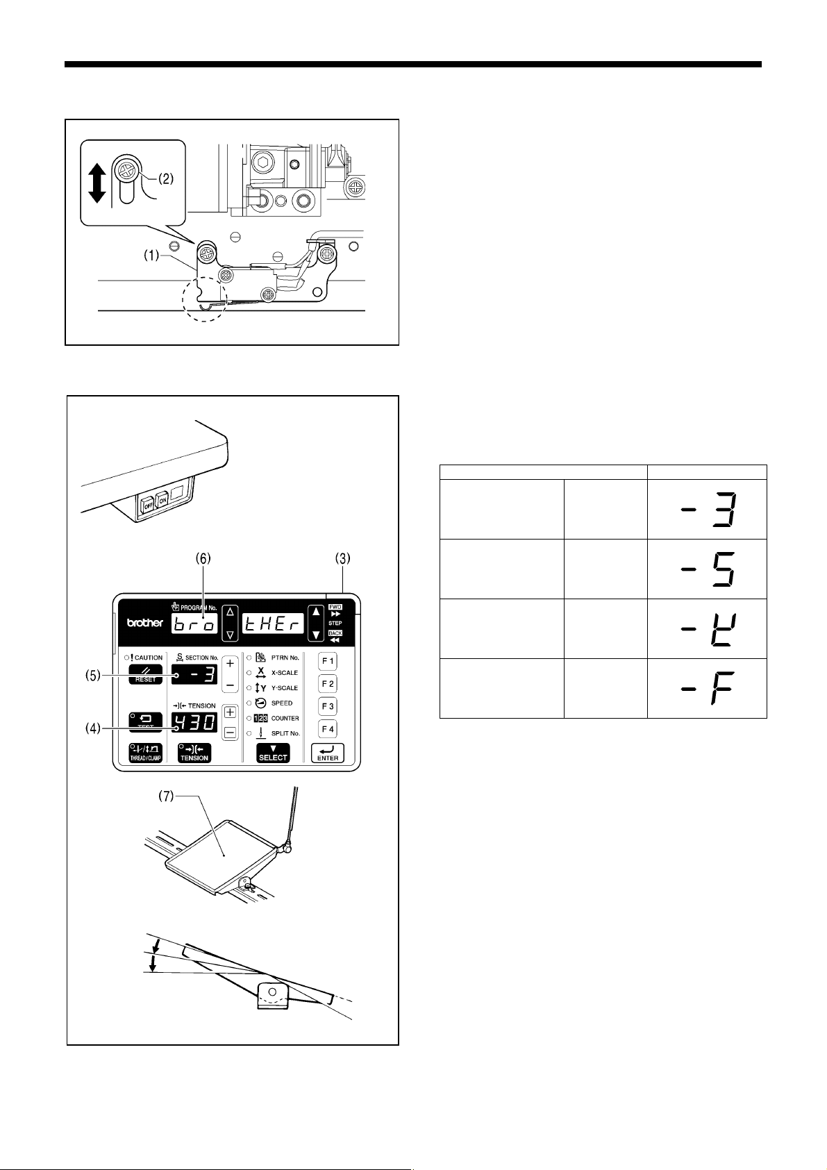
y
4-14. Checking the machine head switch
1. Turn on the power switch.
2. Check that no error numbers appear on the operation panel.
<If error [E050], [E051] or [E055] is displayed>
If the machine head switch (1) is not turned on, error [E050],
[E051] or [E055] will occur.
Use the screw (2) to adjust the installation position of the
machine head switch as shown in the illustration.
2295B
4-15. Starting up
4421Q
1. Turn on the power switch.
4. INSTALLATION
The POWER indicator (3) will illuminate, and the model
name will appear in the tension value display (4) and the
specifications will appear in the section No. display (5).
2346B
2nd step
2339B
Specifications Displa
Medium-weight
materials
Heavy-weight
materials
Knitted materials [ - 0K]
Foundation
garments
After this, the program number will flash in the program No.
display (6).
2. Depress the foot switch (7) to the 2nd step.
The feed mechanism will move to the home position and the
work clamp / button clamp will rise.
[ - 03]
[ - 05]
[ - 0F]
KE-430FX/KE-430FS, BE-438FX
25
Page 34
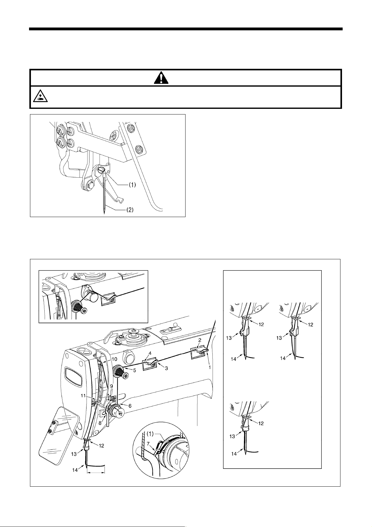
5. PREPARATION BEFORE SEWING
A
5. PREPARATION BEFORE SEWING
5-1. Installing the needle
CAUTION
Turn off the power switch before installing the needle, otherwise the machine may operate if the foot switch is depressed
by mistake, which could result in injury.
2300B
1. Loosen the set screw (1).
2. Insert the needle (2) in a straight line as far as it will go,
making sure that the long groove on the needle is at the
front, and then securely tighten the screw (1).
5-2. Threading the upper thread
Thread the upper thread correctly as shown in the illustration below.
* When using threading mode for threading, the tension discs (1) will open so that the thread can be threaded more easily. (Refer
to following page.)
[When using the needle cooler (option)]
[Two holes]
Spun rayon yarn
[One hole]
Synthetic thread
pprox. 40mm
26 KE-430FX/KE-430FS, BE-438FX
3169B
Page 35
5. PREPARATION BEFORE SEWING
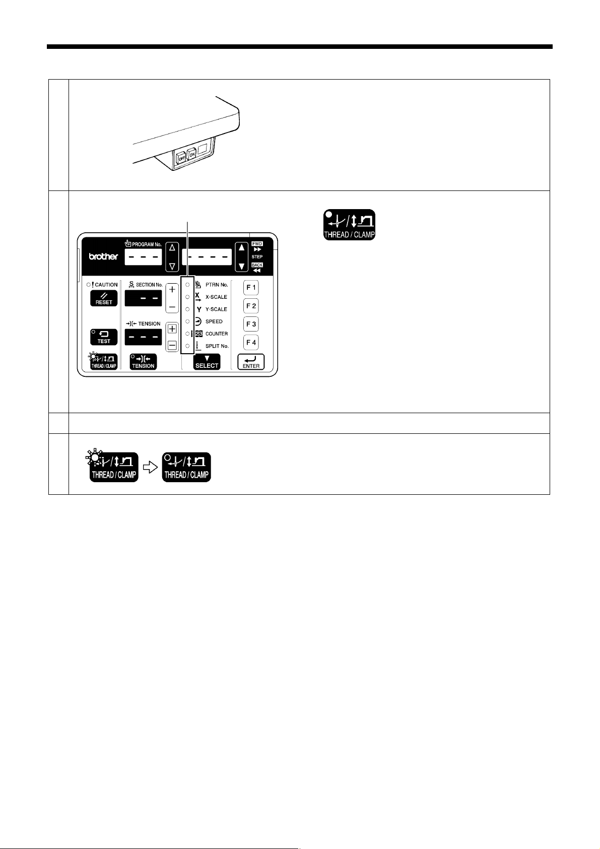
<Threading mode>
Threading mode is safe because the sewing machine will not start even when the foot switch is depressed.
1
2
Threading the thread.
3
Ending threading mode
4
All indicators switch off
THREAD/CLAMP indicator flashes
Menu indicators switch off
THREAD/CLAMP indicator switches off
Turn on the power switch.
Press the THREAD/CLAMP key.
• The work clamp /button clamp will lower.
Press the THREAD/CLAMP key.
• The work clamp/button clamp will return to where it was
before threading mode was started.
4421Q
2340B
2389B
2390B
KE-430FX/KE-430FS, BE-438FX
27
Page 36
5. PREPARATION BEFORE SEWING
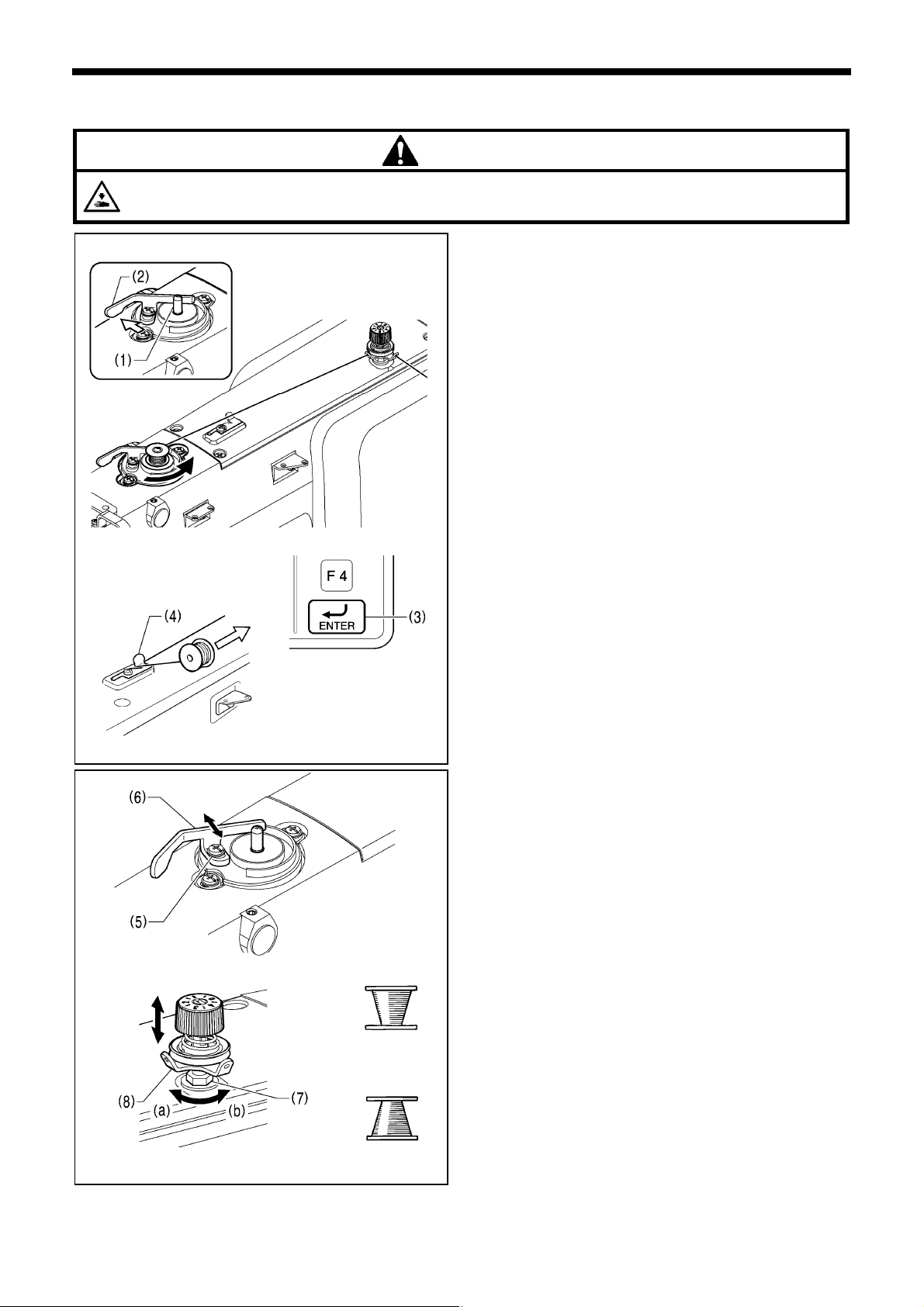
5-3. Winding the lower thread
Do not touch any of the moving parts or press any objects against the machine while winding the lower thread, as this may
result in personal injury or damage to the machine.
CAUTION
3170B
3171B
3172B
3173B
Case A
Case B
2341B
1. Place the bobbin onto the bobbin winder shaft (1).
2. Thread the thread as shown in the illustration, wind the
thread around the bobbin several times, and then press the
bobbin presser arm(2).
3. Turn on the power switch.
4. Depress the foot switch to the second step. The feed
mechanism will move to the home position.
5. Check that the needle is not touching the work clamp/button
clamp, and then while pressing the ENTER key (3), depress
the foot switch to the second step.
6. Release the ENTER key (3) after the machine starts
operating, and keep depressing the foot switch until the
lower thread stops being wound onto the bobbin.
(If you release the foot switch before winding is complete,
and then depress it again while pressing the ENTER key (3),
winding will start again.)
7. Once winding of the set amount of lower thread (80 - 90% of
the bobbin capacity) is completed, the bobbin presser arm
(2) will return automatically.
8. Remove the bobbin, hook the thread onto the knife (4), and
then pull the bobbin in the direction of the arrow to cut the
thread.
Adjusting the bobbin winding amount
Loosen the screw (5) and move the bobbin presser (6).
If the thread winds onto the bobbin unevenly
Loosen the nut (7) and move the bobbin winder tension
assembly (8) up and down to adjust.
* For case A, turn the bobbin winder tension assembly (8)
clockwise (a), and for case B, turn it counterclockwise (b).
28 KE-430FX/KE-430FS, BE-438FX
Page 37
5. PREPARATION BEFORE SEWING
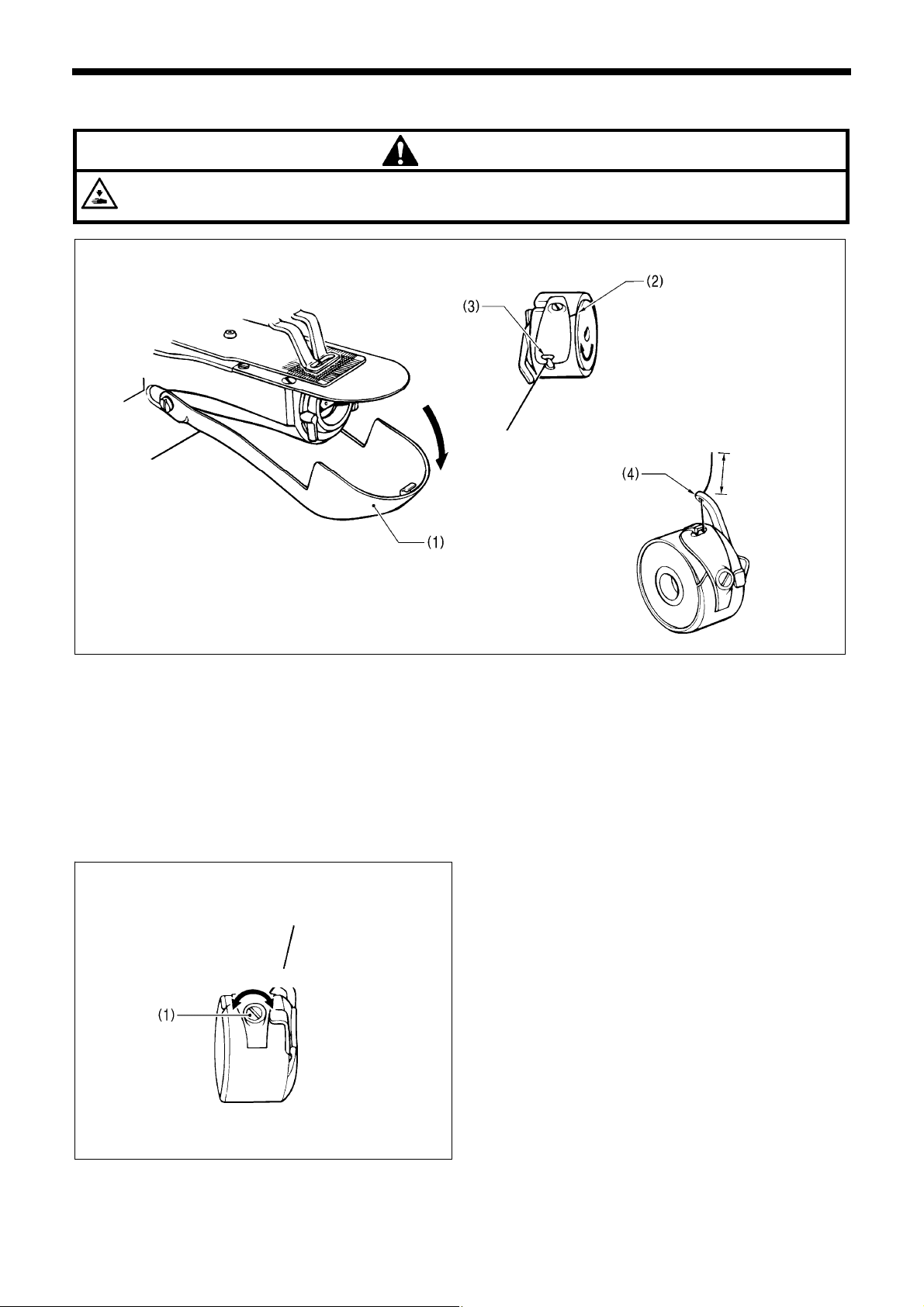
5-4. Installing the bobbin case
CAUTION
Turn off the power switch before installing the bobbin case, otherwise the machine may operate if the foot switch is
depressed by mistake, which could result in injury.
4433Q
1. Pull the shuttle race cover (1) downward to open it.
2. While holding the bobbin so that the thread winds to the right, insert the bobbin into the bobbin case.
3. Pass the thread through the slot (2) and pull it out from the thread hole (3).
4. Check that the bobbin turns in the direction of the arrow when the thread is pulled.
5. Pass the thread through the lever thread hole (4), and then pull out approximately 30 mm of thread.
6. Hold the latch on the bobbin case and insert the bobbin case into the rotary hook.
2534Q
30mm
2535Q
5-5. Thread tension
5-5-1. Lower thread tension
weaker stronger
Adjust the thread tension to the weakest possible tension by
turning the thread tension nut (1) until the bobbin case will
not drop by its own weight while the thread end coming out
of the bobbin case is held.
2536Q
KE-430FX/KE-430FS, BE-438FX
29
Page 38
5. PREPARATION BEFORE SEWING
r
y
–
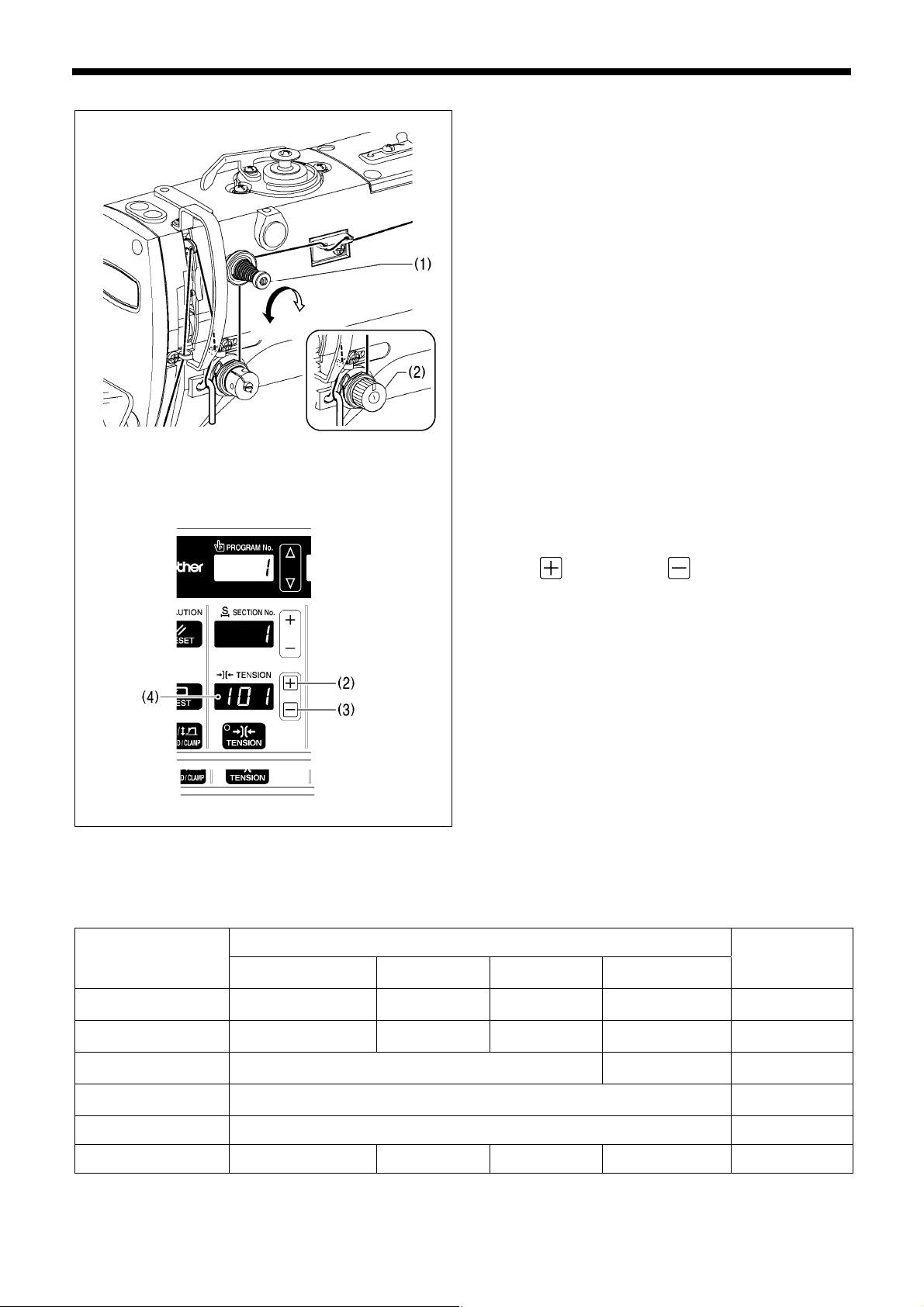
5-5-2. Upper thread tension
Stronger
Weaker
3174B
Use the digital tension or the tension nut (2) to adjust the
tension as appropriate for the material being sewn. (Refer
to "Setting the tension value".)
Furthermore, turn the tension nut (1) (sub-tension) to adjust
the remaining length of upper thread to 35 - 40 mm, when
the
thread take-up lever is not used.
Setting the tension value
<For KE-430FX and BE-438FX>
Press the
key (2) or the key (3) to change the
tension value (4).
* The tension value which has been set will be applied the
next time sewing is carried out.
2345B
[Reference thread tension]
KE-430FX・FS
Use
Medium-weight
materials (-03)
Upper thread #50 or equivalent
Lower thread #50 or equivalent
Upper thread tension
(N) [Tension value] *
1
Lower thread tension
(N)
Knitted wea
(-0K)
#60 or
equivalent
#80 or
equivalent
0.8 - 1.2
[80 - 120]*2
0.2 - 0.3 0.2 - 0.3
Foundation
garments (-0F)
#60 or
equivalent
#60 or
equivalent
Heav
-weight
materials (-05)
#30 or equivalent #60 or equivalent
#50 or equivalent #60 or equivalent
1.2
1.8
2
[70 - 130]*
Pre-tension (N) 0.05 - 0.3 0.1 - 0.4
2382B
2383B
BE-438FX
0.5 - 1.2
[50 - 150]*2
Needle DP x 5 #14 DP x 5 #9 DP x 5 KN#11 DP x 17NY #19 DP x 17NY #12
*1: For KE-430FX and BE-438FX.
*2: This is the tension value when the pretension is 0.05 N.
30 KE-430FX/KE-430FS, BE-438FX
Page 39
[Guide to maximum sewing speed for KE-430FX・FS]
5. PREPARATION BEFORE SEWING
Use
Standard hook Large hook
8 layers of denim 3,200 2,500
12 layers of denim 2,700
Ordinary materials 2,700 2,500
For knitted materials and
foundation garments
NOTE:
The thread may break due to heat under some sewing conditions. If this happens, reduce the sewing speed, or use the
needle cooler (option).
Max. sewing speed (sti/min)
2,500
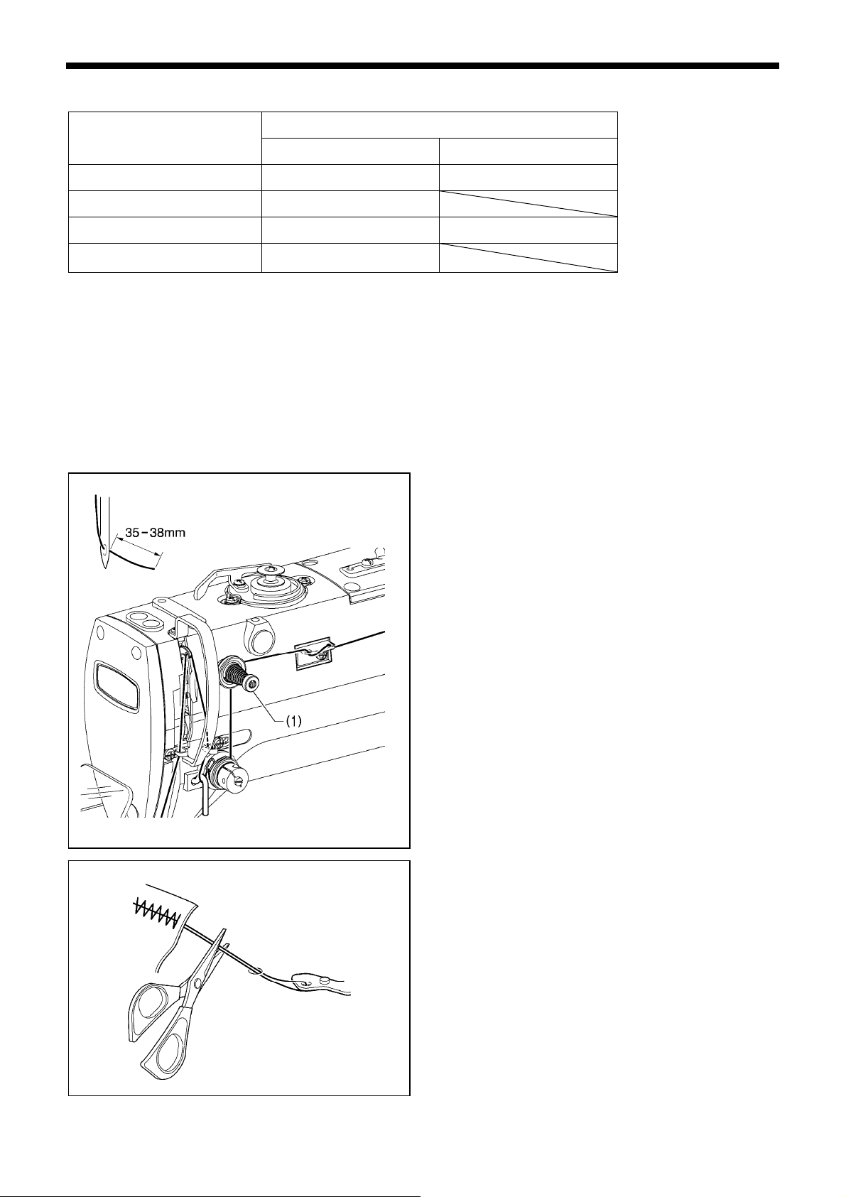
5-6. Thread nipper device <KE-430FX-03, -0K, -0F>
This is used to stop the thread from pulling out at the sewing start, and at times when skipped stitches might easily occur.
The thread nipper device operates when memory switch no. 500 is set to "ON". However, some limitations apply. Refer to
"6-2. List of memory switches" in the instruction manual CD for details.
* The default setting for this memory switch is "OFF".
[Notes on use]
1. When using the thread nipper device, turn the tension
nut (1) (sub-tension) to adjust the upper thread trailing
length to 35 - 38 mm.
* Adjust the upper thread trailing length to less than 40
mm after replacing the upper thread also.
3175B
4475Q
KE-430FX/KE-430FS, BE-438FX
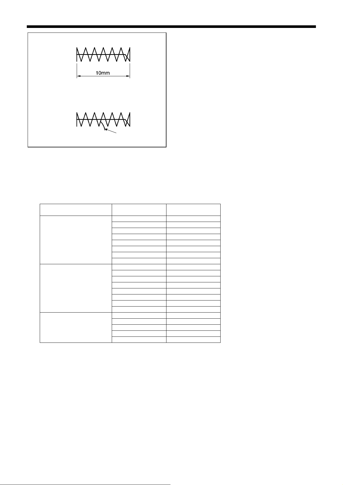
2. If the upper thread trailing length is 40 mm or more, or if
the upper thread tension is weak and the upper thread
does not form a good seam at the first stitch, the end of
the thread that is being held by the thread nipper may
become wound around the seam.
Furthermore, if using thick thread that is #30 or higher or
if the thread trailing length is too long, an error [E691]
may occur.
In any of these cases, use scissors to cut the thread
without pulling it up too hard.
31
Page 40
5. PREPARATION BEFORE SEWING
3. For sewing patterns with a short bar tack length (10 mm
or less), the end of the thread that is being held by the
(Front)
thread nipper may poke out from the seam on the
underside of the material. It is recommended that you
change the thread nipper setting to "OFF" for patterns
such as these.
4. If error [E690] or [E691] frequently occurs, remove the
needle plate and remove any thread scraps from
underneath the needle plate.
(Back)
Upper thread
4487Q
5. With the KE-430FX, the lower thread may poke out from the underside of the material on the 2nd stitch for some types of
material and thread. If this happens, it is recommended that you use sewing patterns that are designed for use with the
thread nipper device.
Refer to "3-1. List of Sewing Patterns (KE-430FX・FS)" for details of the sewing patterns.
<Program No. Reference Table>
Specifications Standard pattern No.
For medium-weight
materials (-03)
For heavy-weight materials
(-05)
For knitted wear (-0K)
For foundation garments (-0F)
Pattern No. for
thread nipper device
1 65
4 66
5 67
8 68
13 69
15 70
20 71
21 72
2 78
3 79
6 80
14 81
16 82
17 83
18 84
19 85
7 73
9 74
22 75
31 76
32 77
32 KE-430FX/KE-430FS, BE-438FX
Page 41
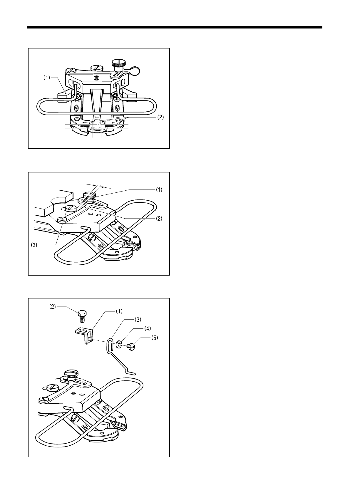
5-7. Inserting the button (BE-438FX)
1. Press the button clamp plate cam (1) to open the button
holder (2).
2. Insert the button, making sure that the button is facing
the directing shown in the illustration, then release the
button clamp plate cam (1).
4115M
5-8. Adjusting the button clamp (BE-438FX)
1. Insert the button in the button clamp, and then confirm
0.5 - 1.0mm
2660Q
that the button is securely held by the clamp and that the
button can be turned by hand.
2. Loosen the shoulder screw (1), while the button is held
by the clamp. Move the adjusting plate (2) so that the
space between the adjusting plate (2) and screw (3) is
approximately 0.5 - 1.0 mm, then tighten the shoulder
screw (1).
5. PREPARATION BEFORE SEWING
5-9. Installing the accessory spring (BE-438FX)
If you would like the button to be raised up more after it is
sewn, install the accessory spring.
1. Install the spring support (1) with the bolt (2).
2. Install the spring (3) with the washer (4) and the screw
(5).
* Adjust so that the spring (3) is in the middle of the
button.
2308B
KE-430FX/KE-430FS, BE-438FX
33
Page 42
6. USING THE OPERATION PANEL (BASIC OPERATIONS)
6. USING THE OPERATION PANEL (BASIC OPERATIONS)
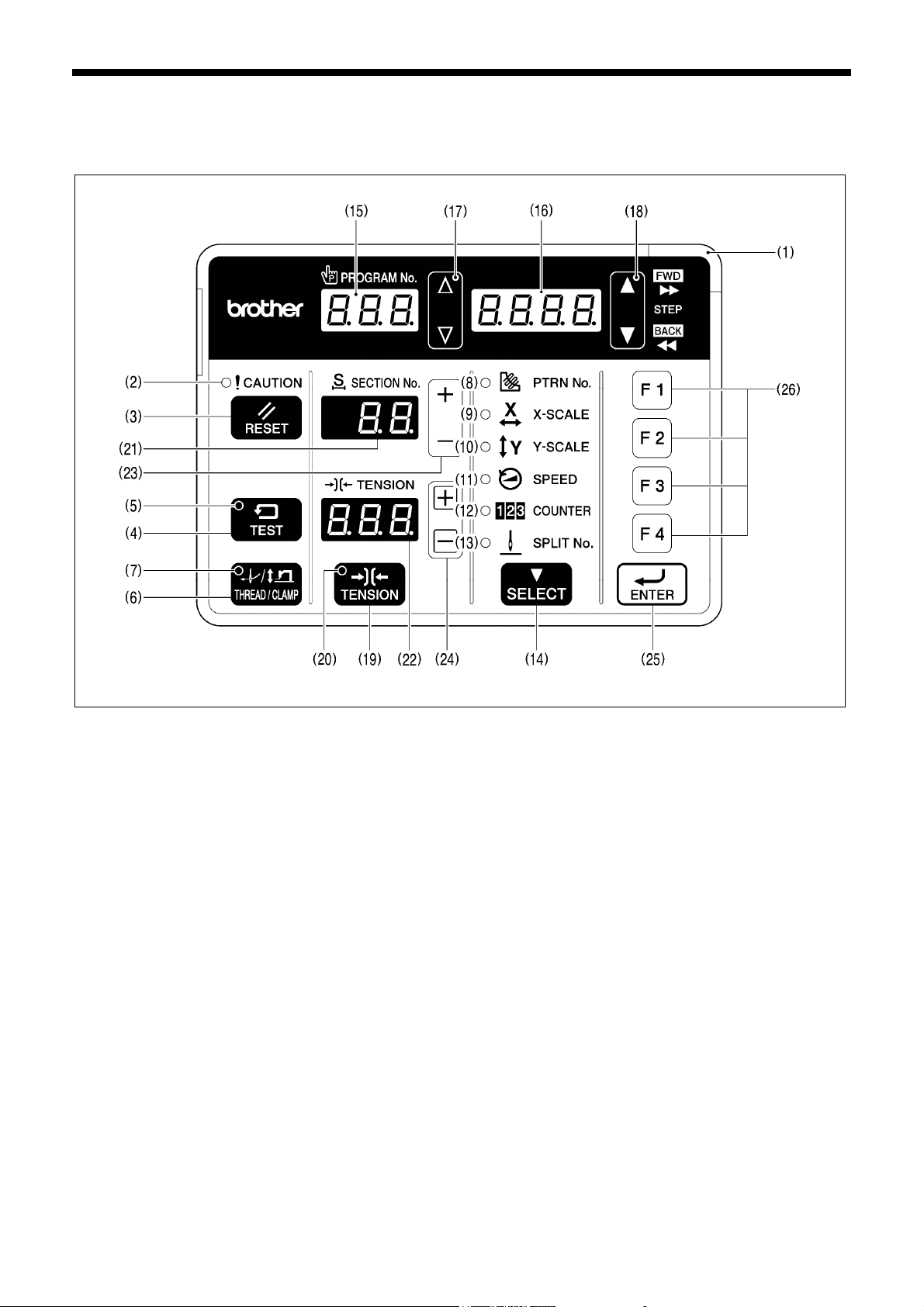
6-1. Name and function of each operation panel item
(1) Power indicator
Illuminates when the power is turned on.
(2) CAUTION indicator
Illuminates when an error occurs.
(3) RESET key
Used to reset errors.
(4) TEST key
Used to switch to test mode, or it can be used in combination with other keys to switch to other setting modes.
(5) TEST indicator
Illuminates when the TEST key (4) has been pressed.
(6) THREAD/CLAMP key
Used to switch to threading mode.
(7) THREAD/CLAMP indicator
This illuminates when the work clamp/button clamp is switched in threading mode or by using the SELECT key (14).
(8) PATTERN No. indicator
Illuminates when the SELECT key (14) is pressed to switch to the pattern number.
(9) X-SCALE indicator
Illuminates when the SELECT key (14) is pressed to switch to the X-scale setting.
(10) Y-SCALE indicator
Illuminates when the SELECT key (14) is pressed to switch to the Y-scale setting.
(11) SPEED indicator
Illuminates when the SELECT key (14) is pressed to switch to the sewing speed setting.
2395B
34
KE-430FX/KE-430FS, BE-438FX
Page 43

6. USING THE OPERATION PANEL (BASIC OPERATIONS)
(12) COUNTER indicator
Illuminates when the SELECT key (14) is pressed to switch to the lower thread or production counter setting.
(13) SPLIT No. indicator
Illuminates when the SELECT key (14) is pressed to show the split setting when split data (for specifying a pause while the
program is running) exists.
(14) SELECT key
Used to switch the menu display (pattern No., X-scale and Y-scale, sewing speed, work clamp/button clamp lift amount,
counter).
(15) PROGRAM No. display
This shows information such as program numbers.
(16) Menu display
Displays information such as menu setting values, memory switch settings and error codes.
(17) Setting keys
Used to change the value which is displayed in the PROGRAM No. display (15).
(18) Setting keys
Used to change the value which is displayed in the menu display (16).
(19) TENSION key
Used to switch to tension correction value display mode.
(20) TENSION indicator
Illuminates when in tension correction value display mode.
(21) SECTION No. display
Shows the section number when you select a pattern in which the upper thread tension changes while the pattern is being
sewn.
(22) TENSION display <For KE-430FX and BE-438FX>
Shows the upper thread tension value.
(23) Setting keys [+, -]
Used to change the value which is displayed in the SECTION No. display (21).
(24) Setting keys [ ]
Used to change the value which is displayed in the TENSION display (22).
(25) ENTER key
Used to accept the values which are displayed in places such as the menu display (16).
(26) Function keys [F1, F2, F3, F4]
Used to directly select program numbers and cycle program numbers.
KE-430FX/KE-430FS, BE-438FX
35
Page 44
6. USING THE OPERATION PANEL (BASIC OPERATIONS)
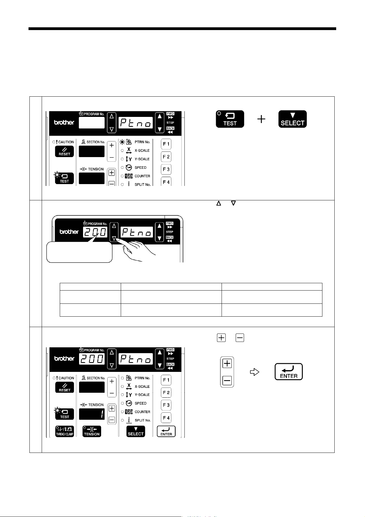
6-2. Program setting method
Patterns, X-scale, Y-scale, sewing speed, slow start pattern and upper thread tension can be recorded into programs.
When a program number is selected, the program which has been set for that number can then be sewn.
Program numbers 1 to 89 (1 to 64 for the 438FX) have patterns preprogrammed into the program numbers with the same numbers
as the pattern numbers, and these pattern numbers cannot be changed. All items in program numbers 200 to 999 can be set as
desired by the user.
Switch to program mode.
1
While pressing the TEST key, press the SELECT key.
TEST indicator flashes, PTRN No. indicator illuminates
Select the program number that you would like to
2
change the parameters for.
For example, program
number 200
Restrictions due to program numbers selected
Program No.
Pattern selection
1 to 89 (430FX・FS), 1 to 64 (438FX)
Not possible Can be recorded as desired
operation
Patterns that can be
recorded
Patterns with same number as program
number already recorded
・ The program number will be displayed in the
PROGRAM No. display, and “Ptno” will be displayed in
the menu display.
・ If a pattern has been recorded in a program, the number
for that pattern will be displayed in the TENSION
display, and if no pattern has been recorded, “—“ will be
displayed.
2396B 2397B
Press the or key to set the program number that you
would like to record.
・ Program numbers 1 to 89 (1 to 64 for the 438FX) have
the following restrictions. If you would like to create your
own programs using sewing patterns, use program
numbers 200 to 999.
2398B
200 to 999
All patterns recorded in the sewing
machine
(If program number 200 to 999 is selected)
3
Record a pattern.
36
Press the
and then press the ENTER key to apply the change.
・ The setting ranges for other items will vary in
accordance with the pattern which is recorded, so
record the pattern first.
・ If “---“ is recorded as the pattern number, that particular
program will no longer have anything recorded.
・ If the display is flashing, it means that no pattern number
has been entered and applied. If you press the SELECT
2399B
KE-430FX/KE-430FS, BE-438FX
key or the TEST key, the changes to the program
contents will be canceled.
or key to change the pattern number,
2400B
Page 45
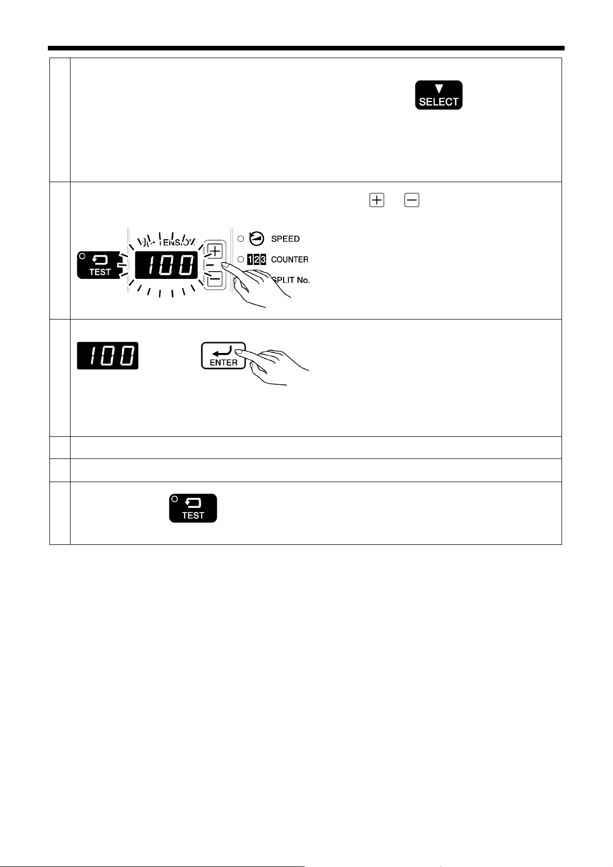
Select the item to be changed.
4
Pattern Æ X-scale Æ Y-scale Æ Sewing speed Æ Slow start patternÆ Upper thread tension
Change the setting for the parameter.
5
(Refer to “List of parameters” on the next page for details
on parameter changes. )
6. USING THE OPERATION PANEL (BASIC OPERATIONS)
Press the SELECT key.
・ The selected parameter changes in the order shown in
the illustration below each time the SELECT key is
pressed.
Press the
setting.
・ The flashing display means that the parameter setting
has not yet been applied.
・ You can make the initial setting appear in the display
by pressing the RESET key.
or key to change the parameter
2401B
2382B 2383B
Apply the changed parameter setting.
6
Repeat steps 4 to 6 above to record the settings for each parameter.
7
If you would like to continue setting another program, repeat steps 2 to 7 above.
8
Exit program mode.
9
2404B
TEST indicator switches off
2402B
2403B
Press the ENTER key.
・ The display will change from flashing to illuminated,
and this means that the setting has been applied.
・ If you press the SELECT key or the TEST key without
pressing the ENTER key, you can cancel the
parameter changes.
Press the TEST key.
・The display will return to the normal display.
KE-430FX/KE-430FS, BE-438FX
37
Page 46
6. USING THE OPERATION PANEL (BASIC OPERATIONS)
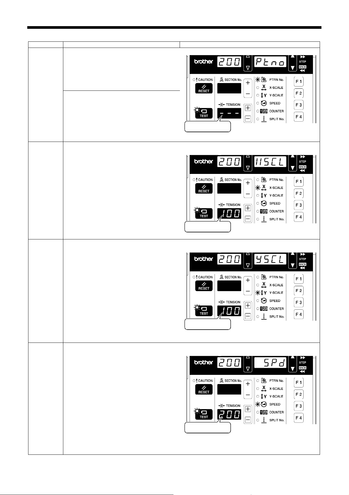
<List of parameters>
Parameter Setting range and initial value Display
[For program numbers 1 to 89 (1 to 64 for the
438FX)]
The setting cannot be changed.
Pattern
[For program numbers 200 to 999]
“---“, 1 to 89 (1 to 64 for the 438FX), additional
recorded pattern numbers.
Initial value
X-scale
20% - 200%
(Limited by available sewing area.)
(Initial value is 100%.)
* The setting can be displayed in “mm” units by
setting memory switch No. 402 to “ON”.
2405B
Y-scale
Sewing
speed
20% - 200%
(Limited by available sewing area.)
(Initial value is 100%.)
* The setting can be displayed in “mm” units by
setting memory switch No. 402 to “ON”.
430FX・FS: 200 sti/min to 3200 sti/min
438FX: 200 sti/min to 2700 sti/min
Setting units are 100 sti/min.
(Initial value is 2000 sti/min.)
* The setting is displayed in units of 10 sti/min.
For a setting of 2000 sti/min, the display will
be “200”.)
Initial value
2406B
Initial value
2407B
38
Initial value
2408B
KE-430FX/KE-430FS, BE-438FX
Page 47
6. USING THE OPERATION PANEL (BASIC OPERATIONS)
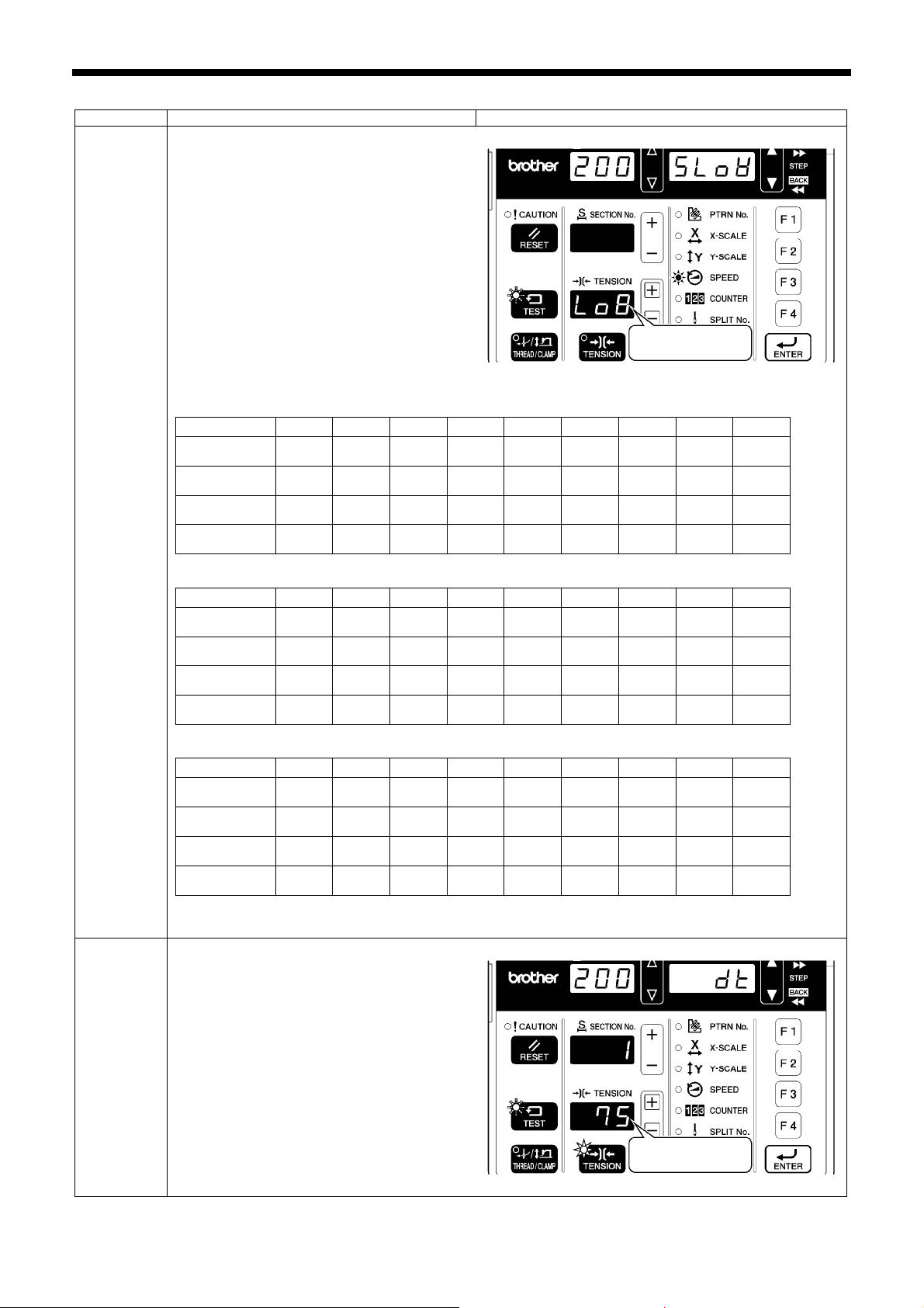
Parameter Setting range and initial value Display
Lo1-Lo9
(Initial values: 430FX・FS: Lo8, 438FX: Lo7)
The starting-up speed at the sewing start can
be adjusted.
* The smaller the number, the slower the start.
* This is used to stop the thread from pulling
out at the sewing start, and at times when
skipped stitches might easily occur.
Initial value
Slow start
pattern
430FX・FS: Medium-weight materials (-03), knitted wear (-0K), foundation garments (-0F)
Sewing speed
for 1st stitch
Sewing speed
for 2nd stitch
Sewing speed
for 3rd stitch
Sewing speed
for 4th stitch
430FX・FS: Heavy-weight materials (-05)
Sewing speed
for 1st stitch
Sewing speed
for 2nd stitch
Sewing speed
for 3rd stitch
Sewing speed
for 4th stitch
438FX
Sewing speed
for 1st stitch
Sewing speed
for 2nd stitch
Sewing speed
for 3rd stitch
Sewing speed
for 4th stitch
* The speed will not be faster than the sewing speed which has been set.
* The thread nipper device will not operate for settings other than Lo8 and Lo9.
Lo1 Lo2 Lo3 Lo4 Lo5 Lo6 Lo7 Lo8 Lo9
200 200 300 400 400 400 400 800 1500
200 300 400 400 500 600 800 1200 3000
300 400 500 600 800 800 1200 2500 3200
500 600 700 900 1200 1200 2500 3200 3200
(sti/min)
Lo1 Lo2 Lo3 Lo4 Lo5 Lo6 Lo7 Lo8 Lo9
200 200 300 400 400 400 800 1500 1500
200 300 400 400 600 800 1200 2000 3000
300 400 500 600 800 1200 2500 2500 3200
500 600 700 900 1200 2500 3200 3200 3200
(sti/min)
Lo1 Lo2 Lo3 Lo4 Lo5 Lo6 Lo7 Lo8 Lo9
200 200 300 300 300 400 400 400 400
200 200 300 300 400 400 400 600 900
300 300 300 400 400 400 600 900 1500
300 400 400 400 400 400 900 2000 2000
(sti/min)
2456B
Upper thread
tension
<For
KE-430FX and
BE-438FX>
0 - 300
(Initial setting is “75”.)
* The later the value, the stronger the upper
thread tension.
KE-430FX/KE-430FS, BE-438FX
Initial value
2409B
39
Page 48
6. USING THE OPERATION PANEL (BASIC OPERATIONS)
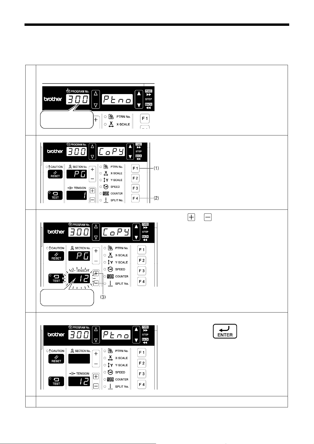
6-3. Copying programs
To create a program with parameters that are almost exactly the same as those of another program, you can copy the original
program and change just the parts which need to be changed.
Select the program number to be used for creating
1
the new program.
For example, to create
program number 300:
Switch to program copy mode.
2
2410B
Carry out steps 1 and 2 in “6-2. Program setting method”
to select the program number to be used for creating the
new program.
• Select a program number from 200 to 999.
While pressing the F1 key (1), press the F4 key (2).
• “CoPy” will be displayed in the menu display, “PG”
will be displayed in the SECTION No. display, and the
number of the program containing the original data will
be displayed in the TENSION display.
Select the program containing the original data.
3
For example, to copy
program number 12:
Copy the program.
4
• The displays will not appear in this way unless a
program number from 200 to 999 has been selected
as the new program number.
2411B
Press the or key (3) to change the number of
the program containing the original data.
• The value in the TENSION display will flash.
• If you press the RESET key, you can cancel the copy
operation and return to program mode.
2412B
Press the ENTER key.
• All parameters in the program will be copied, and the
sewing machine will then return to the status in step 3
of “6-2. Program setting method”.
2382B 2383B
Change the necessary parameters.
5
40
2413B
Carry out the steps from step 4 onward in “6-2. Program
setting method” to change the necessary parameters.
KE-430FX/KE-430FS, BE-438FX
2414B
Page 49
6. USING THE OPERATION PANEL (BASIC OPERATIONS)
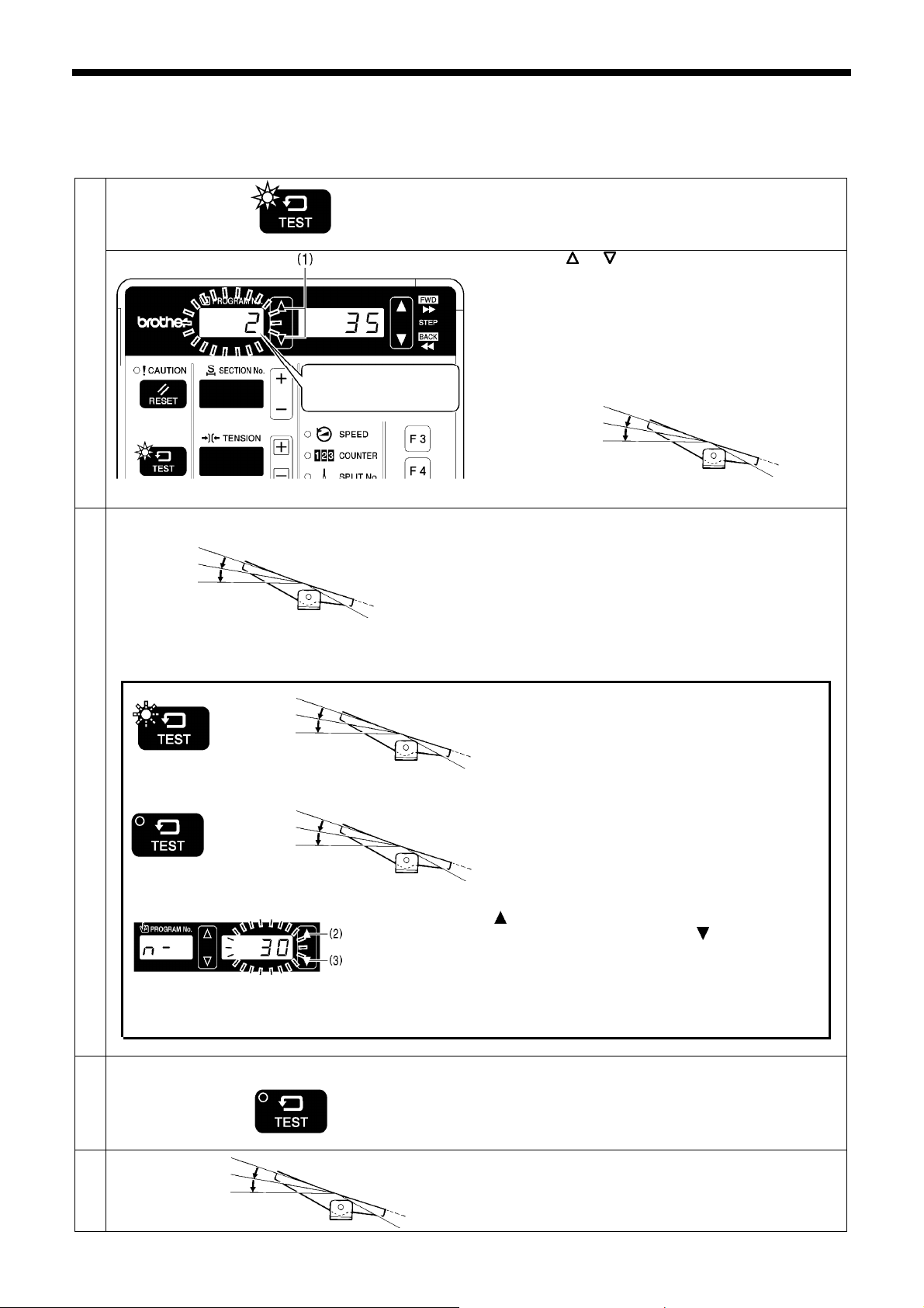
6-4. Checking the sewing pattern (KE-430FX・FS)
Use test feed mode to check the needle movement with only the work clamp operating.
Check that the needle hole does not come out from the frame of the work clamp.
1
1. Press the TEST key.
• The number of stitches remaining until the final stitch
TEST indicator lights
For example, program
number 2
Program No. flashes Æ illuminates
Start continuous test feed mode.
2
4441Q
[Test interrupt mode]
TEST indicator flashes
[Paused sewing standby mode]
TEST indicator switches off
Once the test feed reaches the final stitch, the work
3
clamp stops moving.
2nd step
2nd step
・ If you press the
move forward by one stitch, and if you press the
clamp will move back by one stitch. (It will move quicker if you keep the
key pressed down.)
・ If you press the RESET key, the work clamp will return to the sewing
start position.
will be displayed in the menu display.
2. Press the
that you would like to check.
If the PROGRAM No. display is flashing, depress the foot
switch to the 2nd step.
・ The feed mechanism will move to the home position
and the program number will change from flashing to
illuminated.
Depress the foot switch to the 2nd step and then release it.
・ The work clamp will start moving continuously one
stitch at a time.
(The stitch number display will be decremented by
one stitch at a time.)
・ The TEST indicator will flash.
[Fast-forward test mode]
If you depress the foot switch to the 1st step while the
work clamp is moving, the feeding speed will become
faster while the foot switch is being depressed.
If you would like the work clamp to stop moving, press
the TEST key.
・ When the foot switch is depressed to the 2nd step,
the work clamp will start moving again.
If you would like sewing to resume from the point where it
was paused, press the TEST key while test feeding is
paused to switch off the TEST indicator.
・ When you depress the foot switch to the 2nd step,
sewing will start.
key (2) while in this mode, the work clamp will
Press the TEST key.
or key (1) to set the program number
2nd step
2404B 2416B 4441Q
key (3), the work
2416B
2415B 4441Q
2417B
4
TEST indicator switches off
1st step
KE-430FX/KE-430FS, BE-438FX
Depress the foot switch to the 1st step.
The work clamp will rise and the preparation for sewing
will be completed.
2404B
4441Q
41
Page 50
6. USING THE OPERATION PANEL (BASIC OPERATIONS)
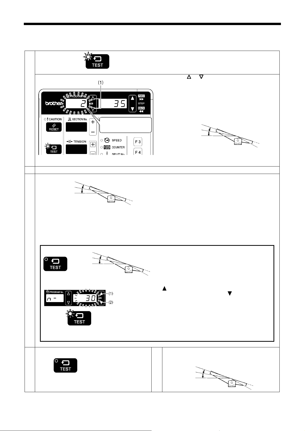
6-5. Checking the sewing pattern (BE-438FX)
Use test feed mode to check the needle movement with only the button clamp operating.
1
TEST indicator lights
For example, program
number 2
Press the TEST key.
・ The number of stitches remaining until the final stitch
will be displayed in the menu display.
2. Press the
or key (1) to set the program number
that you would like to check.
If the PROGRAM No. display is flashing, depress the foot
switch to the 2nd step.
・ The feed mechanism will move to the home position
and the program number will change from flashing to
illuminated.
2nd step
2416B
Program No. flashes Æ illuminates
Set the button. (Refer to “5-7. Inserting the button”.)
2
Start single-stitch test feed mode.
3
2nd step
Depress the foot switch to the 2nd step and then release
it.
・ The button clamp will move by one stitch only.
・ The TEST indicator will flash.
4441Q
After this, the button clamp will move forward by one stitch each time you depress the foot switch to the 1st step. Turn
the pulley by hand each time the button clamp moves by one stitch, and check whether the needle drops into the hole
of the button without touching the button. (If you turn the machine pulley one full rotation in the direction of sewing
machine operation at this time, the button clamp will move forward by one stitch when the needle bar is near the
needle up position.)
In addition, when the foot switch is depressed to the 2nd step, the button clamp will move continuously by 1 stitch at a time as
long as the foot switch is kept depressed.
[Paused sewing standby mode]
TEST indicator switches off
TEST indicator flashes
2nd step
・ If you press the key (1) while in this mode, the button clamp will
move forward by one stitch, and if you press the
clamp will move back by one stitch. (It will move quicker if you keep
the key pressed down.)
・ If you would like to start single-stitch test feed once more, press the
TEST key so that the TEST indicator flashes.
・ If you press the RESET key, the button clamp will return to the sewing
start position.
If you would like sewing to resume from the point
where it was paused, press the TEST key while test
feeding is paused to switch off the TEST indicator.
・ When you depress the foot switch to the 2nd step,
sewing will start.
2404B 4441Q
key (2), the button
End test feeding.
4
Press the TEST key.
Depress the foot switch to the 1st step.
5
The button clamp will be raised and preparation for
sewing will be complete.
1st step
TEST indicator switches off
2404B
2415B
4441Q
2417B
2416B
4441Q
42
KE-430FX/KE-430FS, BE-438FX
Page 51
6. USING THE OPERATION PANEL (BASIC OPERATIONS)
B
B
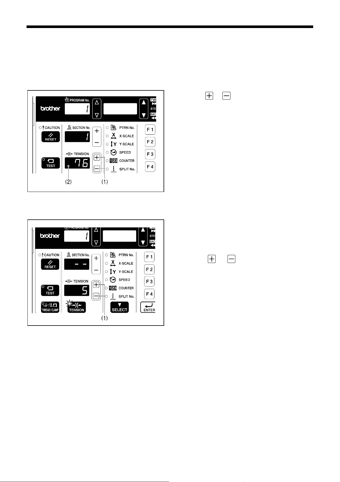
6-6. Correcting the upper thread tension <For KE-430FX and BE-438FX>
The upper thread tension value is always displayed during sewing standby mode, and it can be changed at any time.
<A. Basic method of use>
The changes made at this time will be reflected in each program, so this is a useful way of changing programs while checking actual
sewing.
1. Press the
or key (1) to change the value in the
TENSION display (2).
・ The upper thread tension value which is set will be
applied the next time sewing is carried out.
2418
<B. Overall correction>
This function is useful if you would like to change the tension values for all programs at once.
1. Press the TENSION key.
・ The TENSION indicator will illuminate.
・ The overall correction value will be displayed in the
TENSION display.
2. Press the
or key (1) to change the overall
2419
correction value in the TENSION display.
・ The upper thread tension value which is set will be
applied the next time sewing is carried out.
* The upper thread tension which matches the overall
correction value which has been set for the upper thread
tension will be applied during sewing, regardless of whether
the TENSION indicator is illuminated or switched off.
(In this case, the setting value of “76” which was set in <A.
Basic method of use> has the setting value of “5” added to it
in <B. Overall correction> so that the upper thread tension
applied will be “81”. )
2382B 2383B
KE-430FX/KE-430FS, BE-438FX
43
Page 52
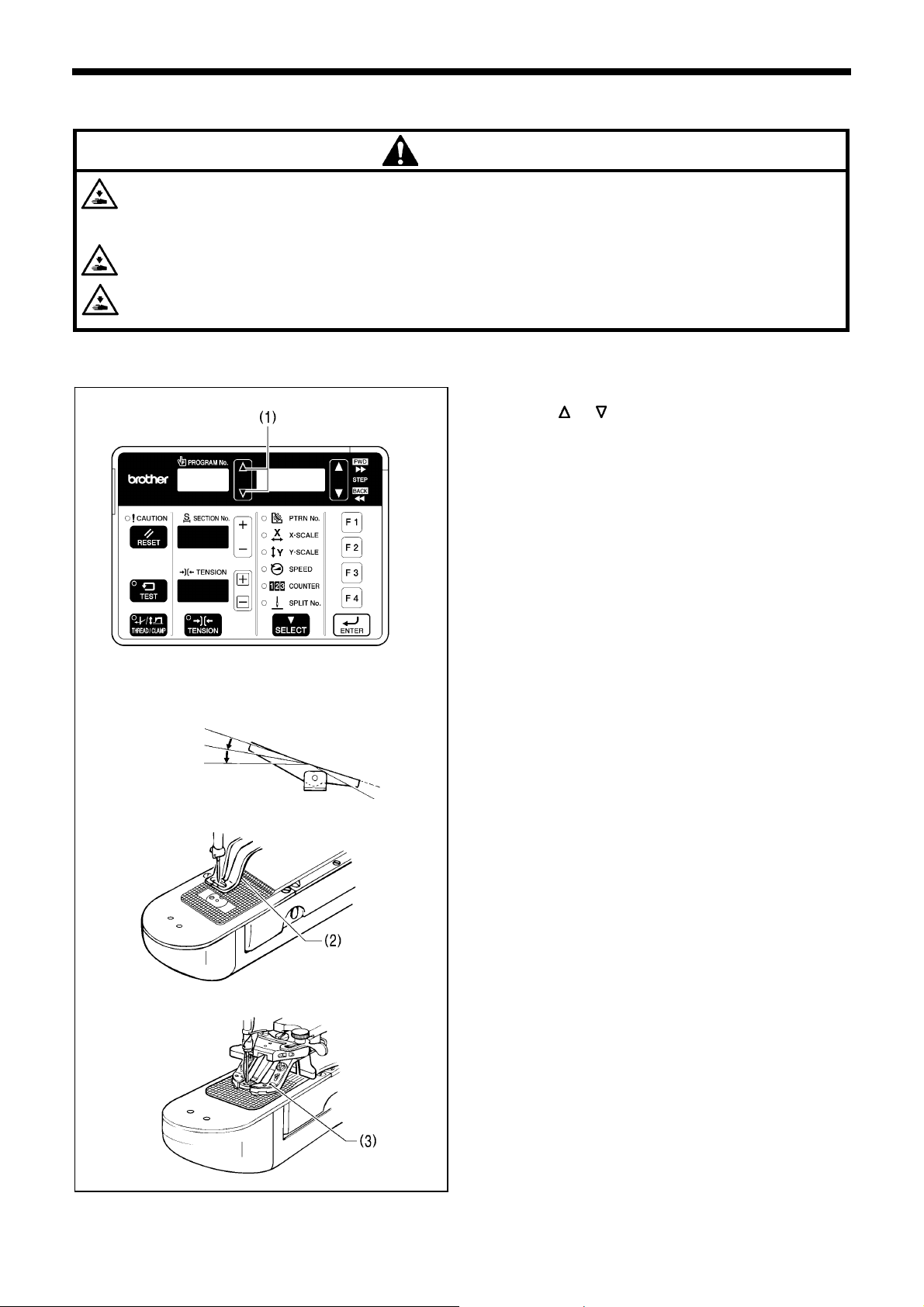
7. SEWING
7. SEWING
Turn off the power switch at the following times, otherwise the machine may operate if the foot switch is depressed
by mistake, which could result in injury.
• When replacing the needle and bobbin
• When not using the machine and when leaving the machine unattended
Use threading mode or turn off the power first in order to carry out threading.
Do not touch any of the moving parts or press any objects against the machine while sewing, as this may result in
personal injury or damage to the machine.
7-1. Sewing
1st step
2nd step
CAUTION
2342B
4441Q
2384B
1. Turn on the power switch.
2. Press the
program to be sewn.
3. Depress the foot switch to the 2nd step.
The feed mechanism will move to the home position.
4. Set the material under the work clamp (2).
(For the BE-438FX, insert the button and place the
material under the button clamp (3). (Refer to “5-7.
Inserting the button”.)
5. Depress the foot switch to the 1st step.
The work clamp (2) / button clamp (3) will be lowered.
6. Depress the foot switch to the 2nd step.
The sewing machine will start sewing.
7. Once sewing is completed and the thread has been
trimmed, the work clamp (2) / button clamp (3) will rise.
or key (1) to select the number for the
4116M
KE-430FX/KE-430FS, BE-438FX 44
Page 53
7. SEWING
7-2. Changing sewing conditions
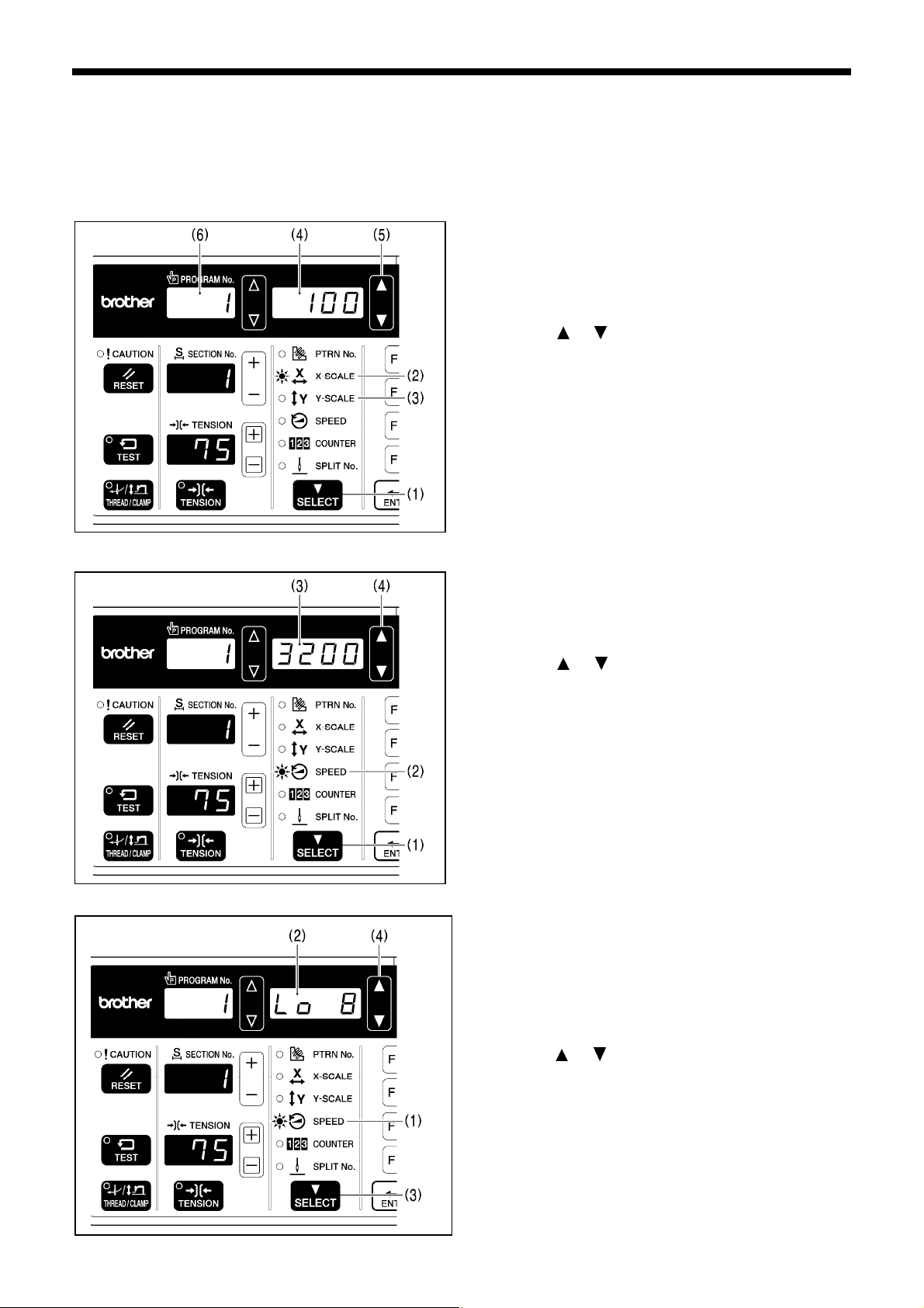
“X-scale”, “Y-scale” and “Sewing speed” can be changed even during sewing standby.
The changes made at this time will be reflected in the program, so this is a useful way of changing programs while checking
actual sewing.
<Changing X-scale and Y-scale>
2450B
1. Press the SELECT key (1) so that the X-SCALE
indicator (2) (for X-scale setting) or the Y-SCALE
indicator (3) (for Y-scale setting) is illuminated.
・ The setting value (%) will be displayed in the menu
display (4).
2. Press the
・ The program number in the PROGRAM No. display
(6) will flash.
3. Depress the foot switch to the 2nd step.
・ The work clamp will move to the sewing start
position and the program number will change from
flashing to illuminated.
NOTE:
Once the setting is complete, be sure to carry out the
steps in "6-4./6-5. Checking the sewing pattern" to check
that the needle drop position is correct.
or key (5) to set the scale (20 - 200).
<Changing the sewing speed>
<Changing slow start pattern>
2451B
1. Press the SELECT key (1) so that the SPEED indicator
(2) is illuminated.
・ The setting value (sti/min) will be displayed in the
menu display (3).
2. Press the
(Sewing speed values: KE-430FX・FS: 200 to 3200;
BE-438FX: 200 to 2700)
* This setting cannot be made when memory switch No.
100 is set to “OFF”.
1. While the SPEED indicator (1) is illuminated and the
sewing speed is being displayed in the menu display (2),
press the SELECT key (3).
• The setting value will be displayed in the menu display
(2).
2. Press the or key (4) to set the slow start pattern.
* Refer to the list of parameters in “6-2. Program setting
method”.
or key (4) to set the sewing speed.
KE-430FX/KE-430FS, BE-438FX 45
Page 54

Document CD
For cleaning, standard adjustments and more details, please refer to the instruction
manual contained in the Document CD.
3168M
Contents of the Document CD
The following documents are contained in PDF format.
Basic Operation Manual
Instruction Manual
Parts Book
Recommended system configuration for using the Document CD
OS: Windows® XP Service Pack 2, Windows Vista®, Windows® 7
Browser version: Microsoft® Internet Explorer 6 Service Pack 1 or higher
Screen resolution: 1024 x 768 pixeles or more
Plug in (required to access): Adobe Reader 8.0 or higher
Adobe, the Adobe logo, and Reader are either registered trademarks or trademarks of Adobe Systems Incorporated in the
United States and/ or other countries.
Windows® and Microsoft® Internet Explorer are either registered trademarks of Microsoft Corporation in the United States
and/ or other countries.
* Please note that the contents of this manual may differ slightly from the actual product purchased as a result of product improvements.
© 2013 Brother Industries, Ltd. All Rights Reserved.
This is the original instructions.
KE-430FX/KE-430FS, BE-438FX
SB4759-001 E
2013.08.B(1)
 Loading...