

Page 1

KE-430B, 430C, 431B, 431C
KE-432B, 432C, 433B
KE-434B, 434C, 435B, 435C
KE-436B, 436C, 484C
SERVICE MANUAL
BE-438B, 438C
Please read this manual before using the machine.
Please keep this manual within easy reach for quick reference.
ELECTRONIC LOCKSTITCH BAR TACKER
ELECTRONIC LOCKSTITCH BELT LOOP BAR TACKER
ELECTRONIC LOCKSTITCH PATTERN TACKER
ELECTRONIC LOCKSTITCH BUTTON SEWER
Page 2
This service manual is intended for KE-430B series, KE-430C series, BE-438B, BE-438C, KE-484C; be sure to read the
KE-430B series, KE-430C series, BE-438B, BE-438C, KE-484C instruction manual before this manual.
Carefully read the “SAFETY INSTRUCTIONS” below and the whole of this manual to understand this product before you
start maintenance.
As a result of research and improvements regarding this product, some details of this manual may not be the same as those
for the product you purchased.
If you have any questions regarding this product, please contact a Brother dealer.
SAFETY INSTRUCTIONS
1. Safety indications and their meanings
This service manual and the indications and symbols that are used on the machine itself are provided in order to ensure
safe operation of this machine and to prevent accidents and injury to yourself or other people.
The meanings of these indications and symbols are given below.
Indications
DANGER
The instructions which follow this term indicate situations where failure to follow the
instructions will almost certainly result in death or severe injury.
CAUTION
Symbols
・・・・・・
・・・・・・
・・・・・・
The instructions which follow this term indicate situations where failure to follow the
instructions could cause injury when using the machine or physical damage to equipment
and surroundings.
This symbol ( ) indicates something that you should be careful of. The picture inside the triangle
indicates the nature of the caution that must be taken.
(For example, the symbol at left means “beware of injury”.)
This symbol ( ) indicates something that you must not do.
This symbol ( ) indicates something that you must do. The picture inside the circle indicates the
nature of the thing that must be done.
(For example, the symbol at left means “you must make the ground connection”.)
i
KE-430B, 430C series
Page 3
2. Notes on safety
Wait at least 5 minutes after turning off the power switch and disconnecting the power cord from the wall outlet
before opening the face plate of the control box. Touching areas where high voltages are present can result in
severe injury.
DANGER
CAUTION
Environmental requirements
Use the sewing machine in an area which is free from
sources of strong electrical noise such as
high-frequency welders.
Sources of strong electrical noise may cause problems with correct operation.
Any fluctuations in the power supply voltage should
be within 10% of the rated voltage for the machine.
Voltage fluctuations which are greater than this may
cause problems with correct operation.
The power supply capacity should be greater than the
requirements for the sewing machine’s electrical
consumption.
Insufficient power supply capacity may cause problems with correct operation.
The pneumatic delivery capability should be greater
than the requirements for the sewing machine’s total
air consumption.
Insufficient pneumatic delivery capability may cause
problems with correct operation.
Installation
Machine installation should only be carried out by a
qualified technician.
Contact your Brother dealer or a qualified electrician
for any electrical work that may need to be done.
The sewing machine weighs more than 52 kg. The
installation should be carried out by two or more
people.
Do not connect the power cord until installation is
complete, otherwise the machine may operate if the
foot switch is depressed by mistake, which could
result in injury.
Hold the machine head with both hands when tilting it
back or returning it to its original position.
Furthermore, after tilting back the machine head, do
not push the face plate side or the pulley side from
above, as this could cause the machine head to
topple over, which may result in personal injury or
damage to the machine.
Be sure to connect the ground. If the ground connec-
tion is not secure, you run a high risk of receiving a
serious electric shock, and problems with correct
operation may also occur.
The ambient temperature should be within the range
of 5C to 35C during use.
Temperatures which are lower or higher than this
may cause problems with correct operation.
The relative humidity should be within the range of
45% to 85% during use, and no dew formation should
occur in any devices.
Excessively dry or humid environments and dew formation may cause problems with correct operation.
Avoid exposure to direct sunlight during use.
Exposure to direct sunlight may cause problems with
correct operation.
In the event of an electrical storm, turn off the power
and disconnect the power cord from the wall outlet.
Lightning may cause problems with correct operation.
All cords should be secured at least 25 mm away
from any moving parts. Furthermore, do not
excessively bend the cords or secure them too firmly
with staples, otherwise there is the danger that fire or
electric shocks could occur.
Install the belt covers to the machine head and motor.
If using a work table which has casters, the casters
should be secured in such a way so that they cannot
move.
Be sure to wear protective goggles and gloves when
handling the lubricating oil and grease, so that they
do not get into your eyes or onto your skin, otherwise
inflammation can result.
Furthermore, do not drink the oil or eat the grease
under any circumstances, as they can cause vomiting
and diarrhoea.
Keep the oil out of the reach of children.
KE-430B, 430C series
ii
Page 4
CAUTION
Sewing
This sewing machine should only be used by operators who have received the necessary training in safe
use beforehand.
The sewing machine should not be used for any
applications other than sewing.
Be sure to wear protective goggles when using the
machine.
If goggles are not worn, there is the danger that if a
needle breaks, parts of the broken needle may enter
your eyes and injury may result.
Set the needle to the needle up stop position before
turning off the power.
If this is not done, the wiper may strike the needle,
which might cause the needle to break.
Turn off the power switch at the following times,
otherwise the machine may operate if the foot switch
is depressed by mistake, which could result in injury.
When threading the needle
When replacing the needle and bobbin
When not using the machine and when leaving the
machine unattended
Cleaning
Set the needle to the needle up stop position before
turning off the power.
If this is not done, the wiper may strike the needle,
which might cause the needle to break.
Turn off the power switch before carrying out
cleaning, otherwise the machine may operate if the
foot switch is depressed by mistake, which could
result in injury.
If using a work table which has casters, the casters
should be secured in such a way so that they cannot
move.
Attach all safety devices before using the sewing
machine. If the machine is used without these
devices attached, injury may result.
Do not touch any of the moving parts or press any
objects against the machine while sewing, as this
may result in personal injury or damage to the
machine.
If an error occurs in machine operation, or if abnormal
noises or smells are noticed, immediately turn off the
power switch. Then contact your nearest Brother
dealer or a qualified technician.
If the machine develops a problem, contact your
nearest Brother dealer or a qualified technician.
Be sure to wear protective goggles and gloves when
handling the lubricating oil and grease, so that they
do not get into your eyes or onto your skin, otherwise
inflammation can result.
Furthermore, do not drink the oil or eat the grease under any circumstances, as they can cause vomiting
and diarrhoea.
Keep the oil out of the reach of children.
Maintenance and inspection
Maintenance and inspection of the sewing machine
should only be carried out by a qualified technician.
Ask your Brother dealer or a qualified electrician to
carry out any maintenance and inspection of the
electrical system.
Set the needle to the needle up stop position before
turning off the power.
If this is not done, the wiper may strike the needle,
which might cause the needle to break.
Turn off the power switch and disconnect the power
cord from the wall outlet at the following times,
otherwise the machine may operate if the foot switch
is depressed by mistake, which could result in injury.
When carrying out inspection, adjustment and main-
tenance
When replacing consumable parts such as the ro-
tary hook
Disconnect the air hoses from the air supply and wait
for the needle on the pressure gauge to drop to “0”
before carrying out inspection, adjustment and repair
of any parts which use the pneumatic equipment.
If the power switch and air need to be left on when
carrying out some adjustment, be extremely careful to
observe all safety precautions.
Hold the machine head with both hands when tilting it
back or returning it to its original position.
Furthermore, after tilting back the machine head, do
not push the face plate side or the pulley side from
above, as this could cause the machine head to
topple over, which may result in personal injury or
damage to the machine.
Use only the proper replacement parts as specified
by Brother.
If any safety devices have been removed, be absolutely sure to re-install them to their original positions
and check that they operate correctly before using
the machine.
Any problems in machine operation which result from
unauthorized modifications to the machine will not be
covered by the warranty.
iii
KE-430B, 430C series
Page 5
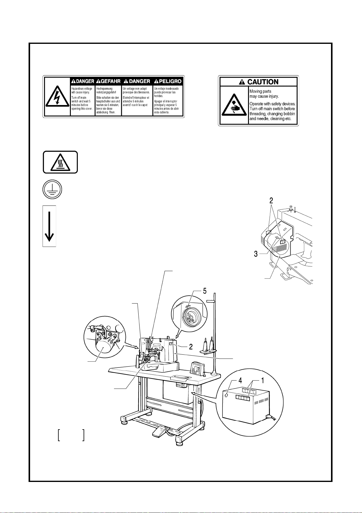
3. Warning labels
The following warning labels appear on the sewing machine.
Please follow the instructions on the labels at all times when using the machine. If the labels have been removed or are
difficult to read, please contact your nearest Brother dealer.
1
2
3
High temperature warning display
Safety devices
Eye guard
Finger guard
Thread take-up cover
Thread take-up solenoid cover
Belt cover
Frame side cover, etc.
4
5
Be sure to connect the ground. If the ground connection is not secure, you run a high risk of receiving a
serious electric shock, and problems with correct operation may also occur.
Direction of operation
Thread take-up cover
Frame
side
cover
e guard
Ey
Thread take-up
solenoid cover
Belt cover
2670Q
Finger guard
KE-430B
KE-430C
KE-430B, 430C series
2737Q
iv
Page 6

CONTENTS
1. SPECIFICATIONS ............................... 1
1-1. SPECIFICATIONS ........................................... 1
1-2. Standard thread tension................................... 5
2. MECHANICAL DESCRIPTIONS ......... 7
2-1. Needle b ar and thread take-up
mechanisms..................................................... 7
2-2. Lo wer shaft and shuttle race mechanisms....... 9
2-3. Work clamp lifter mechanism........................... 10
2-4. Work clamp open-close mechanism
(KE-432B, 432C).............................................. 12
2-5. Thread wiper mechanism................................. 13
2-6. Feed mechanism ............................................. 15
2-7. Thread trimmer mechanism............................. 17
2-8. Thread nipper mechanism ............................... 19
2-9. Thread take-up mechanism ............................. 21
3. DISASSEMBLY ................................... 22
3-1. Covers.............................................................. 22
3-2. Work clamp ar m mechanism
(KE-430B, 430C, 431B, 431C)......................... 24
3-3. Work clamp ar m mechanism
(KE-432B, 432C).............................................. 25
3-4. Work clamp arm mechanism (KE-433B).......... 26
Work clamp arm mechanism (KE-434B, 434C,
3-5.
435B, 435C, 436B, 436C, 484C)
Work clamp arm
3-6.
3-7. Shuttle hook mechanism.................................. 30
3-8. Needle bar mechanism.................................... 31
3-9. Stepping foot mechanism
(KE-435B, 435C, 436B, 436C)......................... 32
3-10. Upper shaft mechanism.................................... 33
3-11. Lower shaft mechanism.................................... 35
3-12. Feed mechanism (1)......................................... 37
3-13. Feed mechanism (2)......................................... 39
3-14. Work clamp lifter mechanism
(Solenoid specifications).................................. 41
3-15. Stepping foot lifter mechanism
(KE-435B, 435C, 436B, 436C)......................... 43
(BE-438B, 438C) ..................... 29
........................... 27
3-16. Thread wiper mechanism.................................. 44
3-17. Thread nipper mechanism ................................ 47
3-18. Thread take-up mechanism .............................. 49
3-19. Thread trimmer mechanism.............................. 51
4. ASSEMBLY......................................... 54
4-1. Thread trimmer mechanism (1)........................ 54
4-2. Thread nipper mechanism................................ 56
4-3. Thread wiper mechanism................................. 59
4-4. Thread take-up mechanism.............................. 62
4-5. Work clamp lifter mechanism
(Solenoid specifications)................................... 65
4-6. Feed mechanism (1)......................................... 70
4-7. Feed mechanism (2)......................................... 74
4-8. Upper shaft mechanism.................................... 76
4-9. Stepping foot lifter mechanism
(KE-435B, 435C, 436B, 436C)......................... 79
4-10. Stepping foot mecha nism
(KE-435B, 435C, 436B, 436C)......................... 80
4-11. Needle bar mechanism..................................... 82
4-12. Lower shaft mechanism.................................... 83
4-13. Thread trimmer mechanism (2) ........................ 86
4-14. Shuttle hook mechanism.................................. 87
4-15. Work clamp arm mechanism
(KE-430B, 430C, 431B, 431C)......................... 89
4-16. Work clamp arm mechanism
(KE-432B, 432C).............................................. 90
4-17. Work clamp arm mechanism (KE-433B)........... 91
4-18. Work
4-19. Work clamp arm mechanism
4-20. Work clamp arm mechanism
4-21. Covers.............................................................. 97
clamp arm mechanism (KE-434B, 434C,
435B, 435C, 436B, 436C, 484C)
(BE-438B, 438C).............................................. 94
(Applying grease) ............................................. 95
........................... 92
KE-430B, 430C series
Page 7

5. ADJUSTMENT..................................... 99
5-1. Adjusting the needle bar height........................ 99
5-2. Adjusting the needle bar lift amount................. 100
5-3. Adjusting the driver needle guard .................... 101
5-4. Adjusting the needle clearance........................ 101
5-5. Adjusting the shuttle race thread guide ............ 102
5-6. Adjusting the clearance between the shuttle
hook and bobbin case holder position bracket
(KE-484C)........................................................ 103
5-7. Adjusting the work clamp lift amount
(KE-430B, 430C, 431B, 431C, 433B) .............. 104
5-8. Adjusting the work clamp lift amount
(KE-432B, 432C).............................................. 104
5-9. Adjusting the work clamp lift amount (KE-434B,
434C, 435B, 435C, 436B, 436C, 484C)........... 105
5-10. Adjusting the button clamp lift amount
(BE-438B, 438C).............................................. 106
5-11. Work clamp pressure adjustment
(KE-432B, 432C).............................................. 107
5-12. Adjusting the holding pressure
(BE-438B, 438C).............................................. 107
5-13. Work clamp closing-distance adjustment
(KE-432B, 432C).............................................. 108
5-14. Adjusting the position of the button holder
(BE-438B, 438C).............................................. 109
5-15. Work clamp adjustment
(KE-435B, 435C, 436B, 436C)......................... 109
5-16. Changing the work clamp lift
(KE-435B, 435C, 436B, 436C)......................... 110
5-17. Adjusting the thread wiper................................ 111
5-18. Adjusting the thread take-up amount................ 114
5-19. Adjusting the movable knife.............................. 116
5-20. Adjusting the position of the thread trimming
link mechanism ................................................ 122
5-21. Adjusting the backlash...................................... 123
5-22. Adjusting the presser solenoid position
(Solenoid specifications) .................................. 124
5-23. Adjusting the sensor perceive plate position
(Solenoid specifications) .................................. 125
5-24. Adjusting the home position.............................. 126
5-25. Adjusting the needle up stop position ............... 129
5-26. Adjusting the tension of the upper shaft timing
belt ................................................................... 129
5-27. Checking the head position switch.................... 130
5-28. Work clamp interchangeability
(KE-433B)....................................................... 131
5-29. Work clamp interchangeability (KE-434B,
434C, 435B, 435C, 436B, 436C, 484C) ........... 131
5-30. Adjustment of air pressure (Pneumatic
specifications)................................................... 132
5-31. Adjustment of inner clamping device ................ 132
6. TROUBLESHOOTING ........................ 133
7. OPTIONAL PARTS............................. 136
8. ELECTRIC MECHANISM.................... 138
8-1. Precautions at the time of adjustment................. 138
8-2. Components inside the control box and
the operation panel........................................... 138
8-3. Fuse explanation ................................................ 139
8-4. Connectors ......................................................... 140
8-5. Explanation of the DIP switches ......................... 147
8-6. Explanation of the memory switches
(KE-430*, 431*, 432*, 433B, 434*, 435*,
484C, BE-438*) ................................................ 150
8-7. Explanation of the memory switches
(KE-436B, 436C).............................................. 155
8-8. Setting the work clamp mode.............................. 159
8-9. Checking the input sensor and DIP switch
input.................................................................. 161
8-10. Checking the input voltage................................ 163
8-11. Clearing all memory settings............................. 164
8-12. Confirming software version ............................. 165
8-13. Table of error codes.......................................... 167
8-14. Troubleshooting................................................ 171
8-15. Control circuit block diagram............................. 190
KE-430B, 430C series
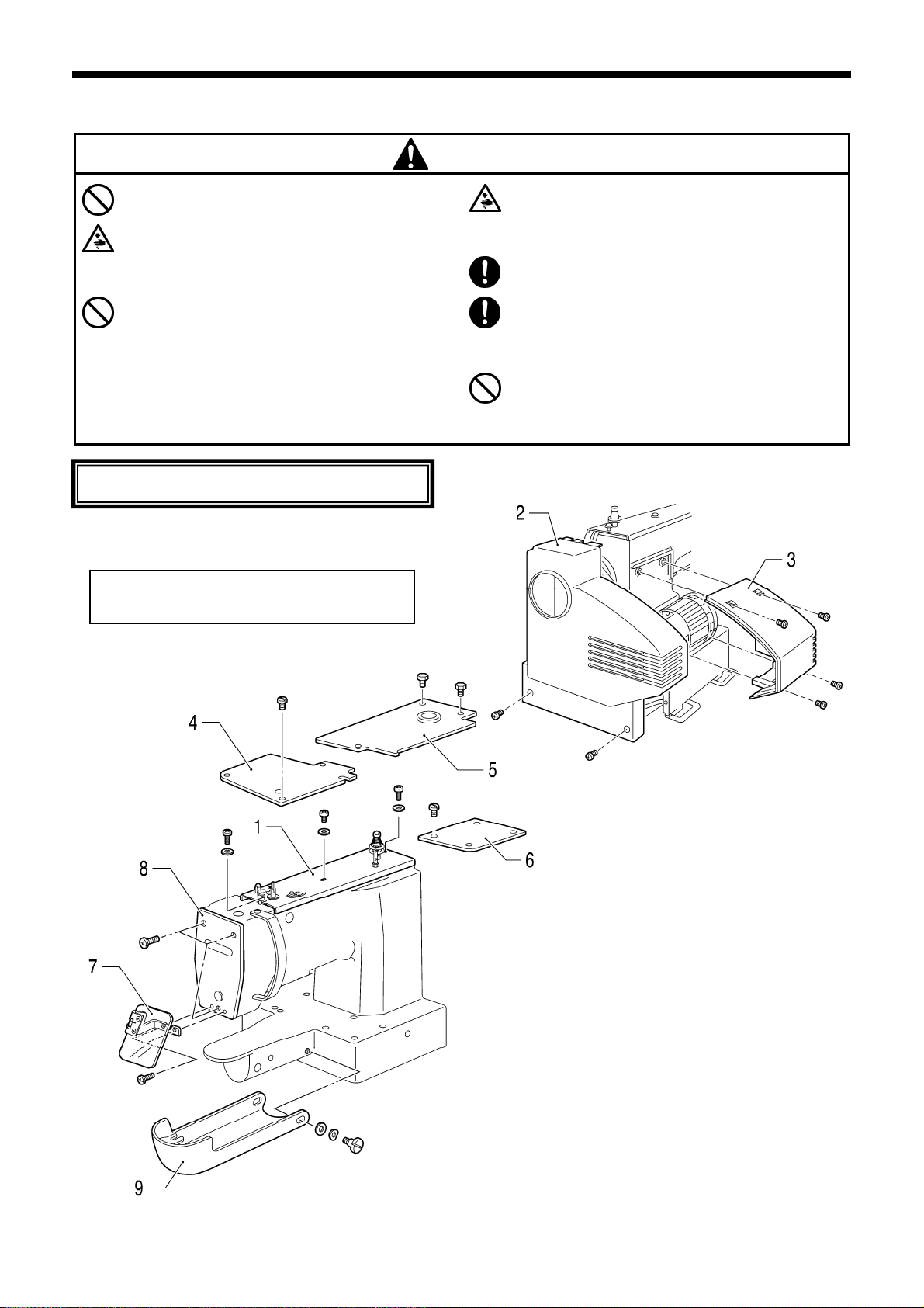
Page 8
1. SPECIFICATIONS
1. SPECIFICATIONS
1-1. SPECIFICATIONS
1
Ordinary materials 2
5
2 Denim
7 Knitted materials
Stitch formation Single needle lock stitch
Maximum sewing speed
Maximum pattern size
Feed mechanism
Stitch length
Number of stitches
Maximum stitch number 20,000 stitches (including 10,000 stitches which can be added)
Work clamp lifter Solenoid type
Work clamp height
Rotary hook Shuttle hook (shuttle hook 2, optional)
Electronic lockstitch
Bar tacking length
Bar tacking length
3
KE-430B
bar tacker
6 -14 mm
14 - 25 mm
30 10 mm max. 12 3 mm max. 30 30 mm max.
R- intermittent feed mechanism (pulse-motor driven mechanism)
KE-431B
Electronic lockstitch
belt loop bar tacker
2,700 rpm 2,500 rpm
0.1 - 10.0 mm
17 mm max.
KE-432B
Electronic lockstitch
eyelet buttonhole
end bar tacker
Variable
1 Ordinary materials
2 Denim
7 Knitted materials
Electronic lockstitch
decorative pattern
KE-433B
tacker
Wiper device Standard equipment
Thread trimmer device Standard equipment
Thread take-up device Standard equipment
Data storage method P-ROM (Any sewing pattern can be added using PS-3000.)
Number of user programs
Number of cycle programs
35 sewing patterns are
Number of stored data
Motor Three-phase 400W induction motor
Weights
Power source
set already
(Up to 100 patterns can be added. Total number of stitches of stored data
6 sewing patterns are
set already
which can be added is within 10,000.)
Machine head: 52 kg, Operation panel: 0.6 kg,
Control box: 9 - 19 kg (depending on destination)
Single-phase 110, 220 - 230, 240V
3-phase 220-230, 380, 400V
Maximum electric power consumption; 600VA
16
4
3 sewing patterns are
set already
1
KE-430B, 430C series
Page 9

1 Medium
materials
2 Heavy materials
KE-436B
KE-434B
Electronic lockstitch
pattern tacker
KE-435B
Electronic lockstitch
pattern tacker
with stepping foot
Electronic lockstitch
pattern tacker
with stepping foot
and programming
function
Stitch formation Single needle lock stitch
1. SPECIFICATIONS
BE-438B
Electronic lockstitch
button sewer
Maximum sewing speed
Maximum pattern size 100 60 mm max.
2,500 rpm (Pitch 3 mm) 2,500 rpm
0 - 6.4 0 - 6.4 mm
Feed mechanism R- intermittent feed mechanism (pulse-motor driven mechanism)
Stitch length
Number of stitches
0.1 - 10.0 mm
Variable
20,000 stitches
Maximum stitch number
20,000 stitches (including 10,000 stitches
which can be added)
20,000 stitches
(One pattern)
(including 10,000
stitches which can
be added)
Work clamp lifter
Work clamp height
Rotary hook
Solenoid type or
pneumatic type
Pneumatic type Solenoid type
17 mm max. (for solenoid)
25 mm max. (for pneumatic) (Max. 17 mm for inner clamping device)
Shuttle hook (shuttle hook 2, optional)
13 mm max.
Wiper device Standard equipment
Thread trimmer device Standard equipment
Thread take-up device Standard equipment
Stepping foot lift amount 18 mm
Stepping foot stroke 0 mm, 3 - 8 mm
Safety device
built-in stopping mechanism
P-ROM (Any sewing
Data storage method
P-ROM (Any sewing pattern can be added
using PS-3000.)
3.5 floppy disk
2HD/1.44MB, 2DD
pattern can be
added using
PS-3000.)
Number of user programs
Number of cycle programs
16
4
16
4
49 sewing patterns are
set already
Number of stored data
(*)
Motor Three-phase 400W induction motor
Weights
Machine head: 56 kg, Operation panel: 0.6 kg (2.8 kg: KE-436B),
Control box: 9 - 19 kg (depending on destination)
Single-phase 110, 220 - 230, 240V
Power source
3-phase 220-230, 380, 400V
Maximum electric power consumption; 600VA
* Up to 100 patterns can be added. Total number of stitches of stored data which can be added is within 10,000.
KE-430B, 430C series
(*)
2
Page 10

1. SPECIFICATIONS
1 Ordinar
y materials
2 Denim
Knitted materials
7
Bar tacking length
2
Bar tacking length
3
6 -14 mm
14 -25 mm
KE-430C
Electronic lockstitch
bar tacker
KE-431C
Electronic lockstitch
belt loop bar tacker
KE-432C
Electronic lockstitch
eyelet buttonhole
end bar tacker
Electronic lockstitch
Stitch formation Single needle lock stitch
Maximum sewing speed
Maximum pattern size
Feed mechanism
Stitch length
Number of stitches
30 26 mm max. 30 10 mm max. 12 3 mm max. 0 - 6.4 0 - 6.4 mm
R- intermittent feed mechanism (pulse-motor driven mechanism)
2,700 rpm 2,500 rpm
0.1 - 10.0 mm
Variable
Maximum stitch number 20,000 stitches (including 10,000 stitches which can be added)
Work clamp lifter Solenoid type
Work clamp height
17 mm max. 13 mm max.
Rotary hook Shuttle hook (shuttle hook 2, optional)
BE-438C
button sewer
Wiper device Standard equipment
Thread trimmer device Standard equipment
Thread take-up device Standard equipment
Data storage method P-ROM (Any sewing pattern can be added using PS-3000.)
Number of user programs
Number of cycle programs
Number of stored data
61 sewing patterns are
set already
(Up to 100 patterns can be added. Total number of stitches of stored data
6 sewing patterns are
set already
16
4
3 sewing patterns are
set already
49 sewing patterns are
which can be added is within 10,000.)
Motor Three-phase 400W induction motor
Weights
Machine head: 52 kg, Operation panel: 0.6 kg,
Control box: 9 - 19 kg (depending on destination)
Single-phase 110, 220 - 230, 240V
Power source
3-phase 220-230, 380, 400V
Maximum electric power consumption; 600VA
set already
3
KE-430B, 430C series
Page 11
1. SPECIFICATIONS
1 Medium
2 Heavy materials
Stitch formation Single needle lock stitch
Maximum sewing speed
Maximum pattern size 100 60 mm max.
Feed mechanism R- intermittent feed mechanism (pulse-motor driven mechanism)
materials
KE-434C
Electronic lockstitch
pattern tacker
KE-435C
Electronic lockstitch
pattern tacker
with stepping foot
2,500 rpm (Pitch 3 mm)
KE-436C
Electronic lockstitch
pattern tacker
with stepping foot
and programming
function
Electronic lockstitch
pattern tacker
with treble hook
KE-484C
2,200 rpm
(Pitch 3 mm)
Stitch length
Number of stitches
0.1 - 10.0 mm
Variable
20,000 stitches
Maximum stitch number
20,000 stitches (including 10,000 stitches
which can be added)
20,000 stitches
(One pattern)
(including 10,000
stitches which can
be added)
Work clamp lifter
Work clamp height
Rotary hook Shuttle hook (shuttle hook 2, optional)
Solenoid type or
pneumatic type
Pneumatic type
17 mm max. (for solenoid), 25 mm max. (for pneumatic)
(Max. 17 mm for inner clamping device)
Treble hook
Wiper device Standard equipment
Thread trimmer device Standard equipment
Thread take-up device Standard equipment
Stepping foot lift amount 18 mm
Stepping foot stroke 0 mm, 3 - 8 mm
Safety device
built-in stopping mechanism
P-ROM (Any sewing
Data storage method
P-ROM (Any sewing pattern can be added
using PS-3000.)
3.5 floppy disk
2HD/1.44MB, 2DD
pattern can be
added using
PS-3000.)
Number of user programs
Number of cycle programs
16
4
16
4
Number of stored data (*)
Motor Three-phase 400W induction motor
Weights
Machine head: 56 kg, Operation panel: 0.6 kg (2.8 kg: KE-436C),
Control box: 9 - 19 kg (depending on destination)
Single-phase 110, 220 - 230, 240V
Power source
3-phase 220-230, 380, 400V
Maximum electric power consumption; 600VA
* Up to 100 patterns can be added. Total number of stitches of stored data which can be added is within 10,000.
KE-430B, 430C series
(*)
4
Page 12

1. SPECIFICATIONS
1-2. Standard thread tension
[KE-430B, 430C, 431B, 431C, 432B, 432C, 433B, 434B, 434C, 435B, 435C, 436B, 436C]
Use
Upper thread
Lower thread
Upper thread tension
(N)
Lower thread tension
(N)
T hread take-up
spring height
(mm)
Thread take-up
s pring tension
(N)
Pre-t (N) ension
Medium materials
(Ordinary materials)
Standard hook Large hook Standard hook Large hook Standard hook
#50 or
equivalent
#60 or
equivalent
0.8 - 1.2 1.0 - 1.3 1.2 - 1.6 1.4 - 1.8 0.8 - 1.2
0.2 - 0.3
6 - 8
0.3 - 0.4
0.5 - 0.8
←
←
←
←
←
←
Heavy materials (Denim) Knitted materials
#30 or
equivalent
#50 or
equivalent
0.2 - 0.3
6 - 8
0.5 - 0.6
0.3 - 0.5
← #60 or equivalent
← #80 or equivalent
←
←
←
←
0.25 - 0.3
6 - 8
0.3 - 0.4
0.5 - 0.8
Needle
[BE-438B, 438C, KE-484C]
Model BE-438B BE-438C KE-484C
Needle
Upper thread #60 or equivalent #60 or equivalent #4 or equivalen t
Lower thread
Upper thread tension
Lo n
T hread take-up
T
spring tension
Pre-tension (N)
(N)
wer thread tensio
(N)
spring height
(mm)
hread take-up
(N)
DP×5#14 ← DP×17NY#19 ← DP×5#9
TQ×1#12 TQ×1# NY#12 12 DP×17 DP×17#25
#60 or equivalent or equivale #4 or equivalent #60 nt
0.7 - 1.3 0.7 - 1.3 0.7 - 1.5 4.5 - 5.0
0 0 1
.3 - 0.4 .3 - 0.4 .0 - 1.2
6 - 8 6 - 8 0 - 5
0.4 - 0.6 0.4 - 0.6 2.0 - 2.5
0.1 - 0.3 0.1 - 0.3 0.05 - 0.3 0.3 - 0.5
5
KE-430B, 430C series
Page 13

1. SPECIFICATIONS
1-2-1. Measuring tension
Upper thread tension Lower thread tension
3564Q 3565Q
Thread take-up spring height Thread take-up spring tension
3566Q
1–2 mm
Measure the value when the thread take-up
spring starts to extend.
3567Q
* When the spring height (stroke) is great or the spring tension is insufficient, it may cause the thread end length to vary after
thread trimming.
KE-430B, 430C series
6
Page 14
2. MECHANICAL DESCRIPTIONS
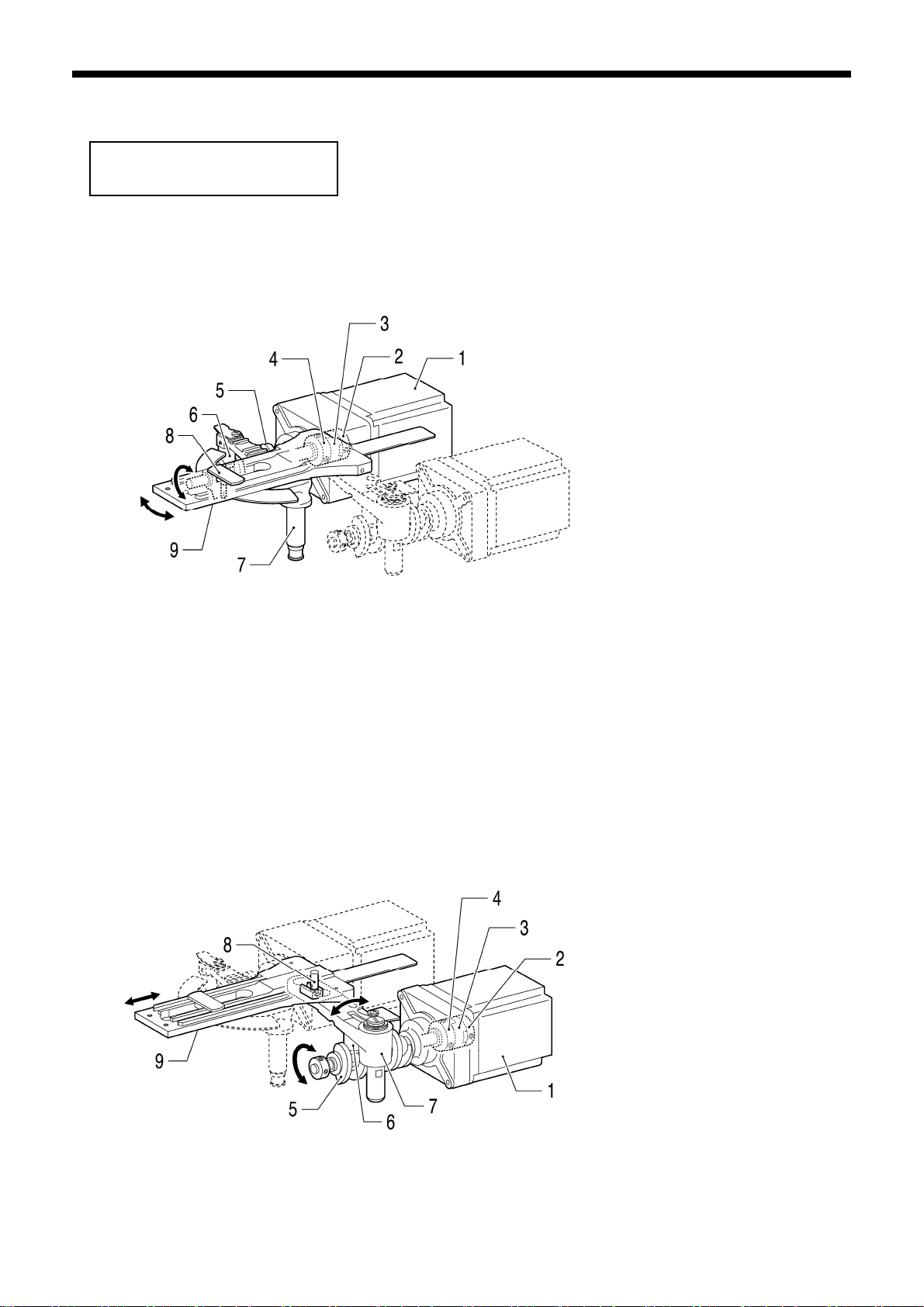
2. MECHANICAL DESCRIPTIONS 2. MECHANICAL DESCRIPTIONS
The mechanisms operate in the order of the numbers given in the illustrations.
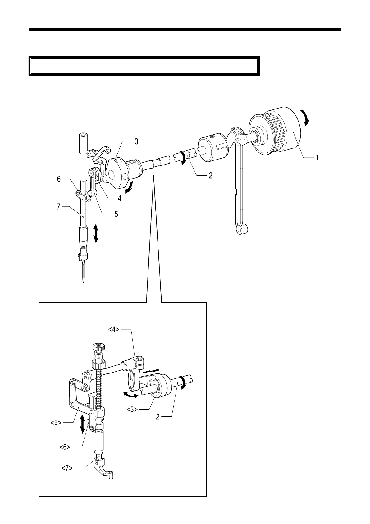
2-1. Needle bar and thread take-up mechanisms 2-1. Needle bar and thread take-up mechanisms
With stepping foot
3240Q 40Q
7
<3> Stepping foot connecting rod
<4> Stepping foot arm
<5> Stepping link assy
<6> Presser bar lifter
<7> Stepping foot
KE-430B, 430C series
1. Pulley
2. Upper shaft
3. Thread take-up crank
4. Needle bar crank
5. Needle ba r conne cting ro d
6. Needle bar clamp
7. Needle bar
Page 15

KE-484C
3241Q 41Q
2. MECHANICAL DESCRIPTIONS
1. Pulley
2. Upper shaft
3. Thread take-up crank
4. Ne
edle bar crank
5. Needle ba r conne cting ro d
6. Needle bar clamp
7. Needle bar
KE-430B, 430C series
8
Page 16
2. MECHANICAL DESCRIPTIONS
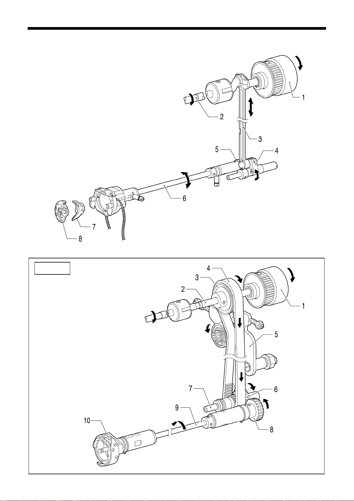
2-2. Lower shaft and shuttle race mechanisms 2-2. Lower shaft and shuttle race mechanisms
3242Q Q
KE-484C
1. Pulley
2. Upper shaft
3. Timing pulley
4. Timing belt
5. Tensi on pulley arm
6. Lower shaft timing pulley
7. Lower shaft
8. Lower gear
9. Rotary hook shaft
1
0.Treble hook assy
1. Pulley
2. Upper shaft
3. Cra
nk rod assy
4. Rock gear
5. Lower gear
6. Lower shaft
7. Driver
8. Shuttle hook
3243
Q3243Q
9
KE-430B, 430C series
Page 17
2. MECHANICAL DESCRIPTIONS
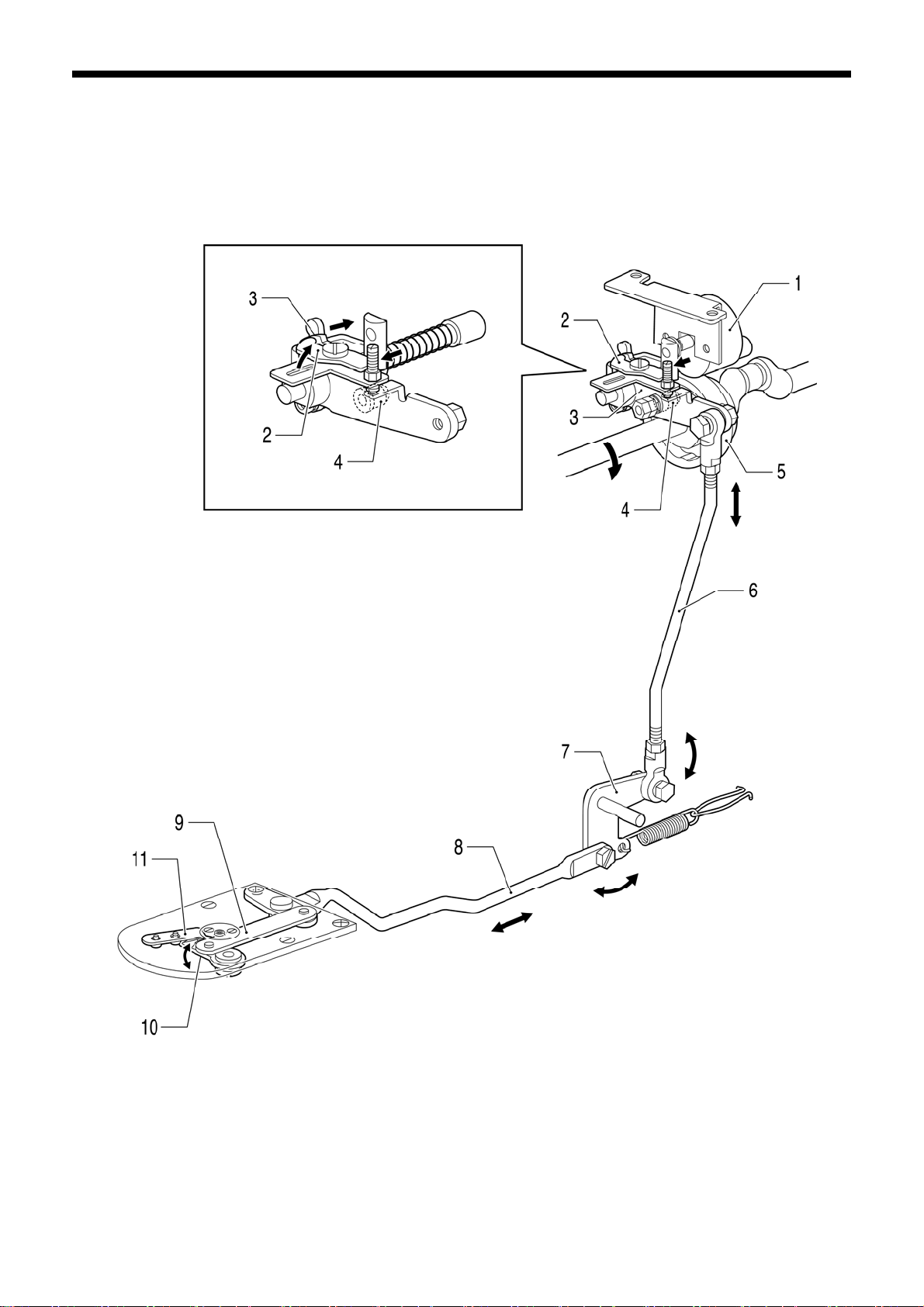
2-3. Work clamp lifter mechanism
1. Work clam p solenoi d
2. Plunger
3. Link assy, C
4. Link shaft, B
5. Link, B
6. Link shaft, C
7. Work clam p plate
8. Work clamp a rm lever plate
9. Work clamp a rm lever shaft
10.Work clamp arm lever
11.Work clamp
* When the presser solenoid is turned off, the
presser plate rises, and work clamp s lo wer.
KE-432B, 432C BE-438B, 438C
3266Q 3267Q
7. Work
clamp lifting rod
8. Work clamp lifter lever
9. Presser adjusting plate assy
10. Button clamp holder shaft
11. Work clamp
7. Work
clamp lifting rod
8. Button clamp lifting lever
9. Button clamp holder hook assy
10. Button clamp holder shaft
11. Button clamp
3244
Q
KE-430B, 430C series
10
Page 18
2. MECHANICAL DESCRIPTIONS
Pneumatic specifications
3245Q45Q
1. Air cylinder
2. Work clamp a rm lever shaft
3. Work clam p arm leve r
4. Work clamp
11
KE-430B, 430C series
Page 19
2. MECHANICAL DESCRIPTIONS
2-4. Work clamp open-close mechanism (KE-432B, 432C)
3262Q
1. Solenoid assy
2. OY solenoid pin
3. Sensor plate
4. Work cla mp c arri er ro d as sy
5. Lever
6. Roller
7. Work clam p carrier plat e
8. Work clam p guid e plate
9. Screw
10.Work clamp
KE-430B, 430C series
12
Page 20
2. MECHANICAL DESCRIPTIONS
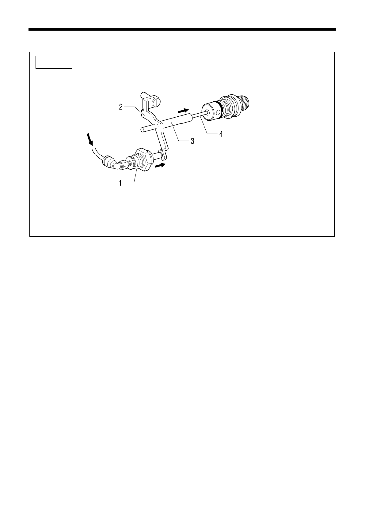
2-5. Thread wiper mechanism 2-5. Thread wiper mechanism
Solenoid type thread wiper
3246Q3246Q
When the presser solenoid is turned off, the
presser plate rises, and thread wiper operates in
the opposite direction.
1. Work clam p solenoi d
2. Plun
ger
3. Link assy, C
4. Link shaft, B
5. Thread wi pe r drivin g lever
6. Thread wi pe r ro d assy
7. Thread wi pe r arm assy
8. Thread wiper
3247QQ
1. Thread wi pe r so le noid
2. Thread wi pe r co nne cting rod as sy
3. Thread wi pe r arm assy
4. Thread wiper
13
KE-430B, 430C series
Page 21

Stepping foot specifications
3248Q Q
KE-484C
3249Q 3249Q
2. MECHANICAL DESCRIPTIONS
1. Thread wi pe r so le noid
2. Thread wi pe r co nne cting rod as sy
3. Thread wi pe r arm assy
4. Thread wiper
1. Thread wi pe r cyli nd er
2.
Thread wiper connecting rod lever
3. Thread wi pe r co nne cting rod
4. Thread wi pe r arm assy
5. Thread wiper
KE-430B, 430C series
14
Page 22

2. MECHANICAL DESCRIPTIONS
2-6. Feed mechanism
Sewing patterns are created through combination s of X and Y movements.
KE-430B, 431B, 432B, 433B, BE-438B
KE-430C, 431C, 432C, BE-438C
X direction
3250Q
Y direction
3251Q
1. Pulse motor, X
2. Coupling hub, 6.35
3. Coupling spacer
4. Coupling hub, 8
5. Feed cam, X
6. Feed cam roller
7. X-feed lever
8.
Tack length regulator block assy
9. Feed bracket
1. Pulse motor, Y
2. Coupling hub, 6.35
3. Coupling spacer
4. Coupling hub, 8
d cam, Y
5. Fee
6. Feed cam roller
7. Y-feed lever
8. Tack width feed shaft
9. Feed bracket
15
KE-430B, 430C series
Page 23
KE-434B, 435B, 436B
KE-434C, 435C, 436C, 484C
X direction
Y direction
2. MECHANICAL DESCRIPTIONS
1. Pulse motor, X
2. Coupling hub, 8
3. Coupling spacer
3252Q
4. Coupling hub, 8
5. Feed cam, X
6. Feed cam roller
7. X-feed lever
8. Tack length regulator block assy
. Feed bracket
9
1. Pulse motor, Y
2. Coupling hub, 8
3. Coupling spacer
4. Coupling hub, 8
3253
Q
5. Feed cam, Y
6. Fee
d cam roller
7. Y-feed lever
8. Tack width regulator block assy
9. Feed bracket
KE-430B, 430C series
16
Page 24
2. MECHANICAL DESCRIPTIONS
2-7. Thread trimmer mechanism
3254Q
1. Thread trimmer solenoid
2. Driving lev er push lever
3. Thread driving lever
4. Thread trimmer roller
5. Thread trimmer cam
6. Thread trimmer rod
7. Thread trimmer lever
8. Connecting rod lever assy
9. Thread trimmer connecting rod
10. Movable knife
11. Fixed knife
17
KE-430B, 430C series
Page 25

KE-484C
3255Q
2. MECHANICAL DESCRIPTIONS
1. Thread trimmer solenoid
2. Driving lev er push lever
3. Thread driving lever
4. Thread trimmer roller
5. Thread trimmer cam
6. Thread trimmer rod
7. Thread trimmer lever
8. Thread trimmer rod, L
9. Thread trimmer connecting rod
10. Movable knife
11. Thread trimmer cylinder
12. Extension rod
13. Fixed knife
KE-430B, 430C series
18
Page 26
2. MECHANICAL DESCRIPTIONS
2-8. Thread nipper mechanism
Manual operation
In thread trimming
3256Q
1. Thread trimmer solenoid
2. Driving lev er push lever
3. Thread driving lever
4. Tension release driving lever
5. Lower thread retainer collar
6. Thread trimmer cam
1. Lifting lever
2. Lifting crank
3. Tensi on release lever
4. Tension release stud
5. Tension release pin
3257Q
7. Tension release driving lever
8. Tension release lever, U
9. Tension release rod assy
10. Tension release lever
11. Tension release stud
12. Tension release pin
19
KE-430B, 430C series
Page 27
KE-484C
3258Q
2. MECHANICAL DESCRIPTIONS
1. Tension release cylinder
2. Tensio n release pin push leve r
3. Tensio n release pin, L
4. Ten
sion release pin
KE-430B, 430C series
20
Page 28
2. MECHANICAL DESCRIPTIONS
2-9. Thread take-up mechanism
Stepping foot specifications
KE-484C
3260
3259Q
1. Th
read take-up solenoid
2. Solenoid joint
3. Thread take-up lever crank
4. Thread take-up lever
Q
3261Q
1. Thread take-up cylinder
2. Thread take-up lever
21
KE-430B, 430C series
Page 29
3. DISASSEMBLY
3. DISASSEMBLY
Disassembly should only be carried out by a
qualified technician.
Turn off the power switch before disassembly,
otherwise the machine may operate if the foot
switch is depressed by mistake, which could
result in injury.
Be sure to wear protective goggles and gloves
when handling the lubricating oil and grease,
so that they do not get into your eyes or onto
your skin, otherwise inflammation can result.
Furthermore, do not drink the oil or eat the
grease under any circumstances, as they can
cause vomiting and diarrhea.
Keep the oil out of the reach of children.
Disassemble each part in order of the numbers.
3-1. Covers
KE-430B, 431B, 432B, 433B, BE-438B
KE-430C, 431C, 432C, BE-438C
CAUTION
3268Q
Disconnect the air hoses from the air supply
and wait for the needle on the pressure gauge
to drop to “0” before disassembly of any parts
which use the pneumatic equipment.
Use only the proper replacement parts as
specified by Brother.
If any safety devices have been removed, be
absolutely sure to re-install them to their
original positions and check that they operate
correctly before using the machine.
Any problems in machine operation which
result from unauthorized modifications to the
machine will not be covered by the warranty.
3269
1. Top cover
2. Belt cover
3. Frame side cover
4. Bed cover, L F
5. Bed cover, L R
6. Bed cover, R
7. Eye guard assy
8. Face plate assy
9. Shuttle race cover assy
Q
KE-430B, 430C series
22
Page 30
3. DISASSEMBLY
KE-434B, 435B, 436B
KE-434C, 435C, 436C, 484C
<KE-435B, 435C>
<KE-436B, 436C>
3269Q
1. Top
cover
3270Q
2. Belt cover
3. Frame side cover
4. Bed cover, L F
5. Bed cover, L R
6. Bed cover, R
7. Eye guard assy
8. B o lt s [2 pcs]
9. Face plate assy
10. Shuttle race cover assy
11. Auxiliary plate supports [2 pcs]
12. Needle plate auxiliary plate
13. Auxiliary plate supports [4 pcs]
23
KE-430B, 430C series
Page 31

3-2. Work clamp arm mechanism (KE-430B, 430C, 431B, 431C)
1. Set screw
2. Needle
3. Needle ba r thre ad gui de
4. B o lt s [2 pcs]
5. Work clamp arm assy
6. Work clamp felt
7. Screws [2 pcs]
8. Feed plate
Be careful not to drop these two bearing balls
when removing the feed bracket assembly.
9. Rubber cap
10. Set screw [Loosen]
11. Tack width feed shaft
12. Rod end
13. Screws [8 pcs]
14. Feed bracket guide plate
15. Feed bracket assy
16. Flat screws [2 pcs]
17. S
crews [2 pcs]
18. Ne
edle plate
Be careful not to drop these three bearing balls
when removing the work clamp arm assembly.
Remove the feed bracket guide
plate and the feed bracket
assembly together as a single unit.
3. DISASSEMBLY
3271Q
3272
Q
KE-430B, 430C series
24
Page 32

3. DISASSEMBLY
3-3. Work clamp arm mechanism (KE-432B, 432C)
Be careful not to drop these two bearing balls
en removing the feed bracket assembly.
wh
1. Set screw
2. Ne
edle
3. Needle ba r thre ad gui de
4. Bolt
5. Nuts [2 pcs]
Adjusting screw
Compression spring
[Push upward and remove horizontally]
6. Set screw s [2 pcs: Loosen]
7. Button c
lamp holder shaft
8. Work clamp arm assy
9. Bolts [2 pcs]
10. Button clamp holder support
11. Work clamp felt
12. Screws [2 pcs]
13. Feed plate
14. Rubber cap
15. Set screw [Loosen]
3273
Remove the feed bracket
guide plate and the feed
bracket assembly together
as a single unit.
3274Q
16. T
ack width feed shaft
17. Rod end
18. Screws [8 pcs]
19. Feed bracket guide plate
20. Feed bracket assy
21. Flat screws [2 pcs]
22. Screws [2 pcs]
23. Needle plate
Q
25
KE-430B, 430C series
Page 33

3-4. Work clamp arm mechanism (KE-433B)
Q
3275
9. Rubber cap
10. Set screw [Loosen]
11. Tack width feed shaft
12. Screws [8 pcs]
13. Feed bracket guide plate
[Pull upward]
14. Screw
15. Cover support stand
16. Feed bracket cover
17. Set
18. Tack length regulator block
19. Feed bracket guide shaft assy
20. Retainer assys [2 pcs]
21. Spacers [2 pcs]
22. Feed bracket assy
23. X fe
24. Y feed cover
25. Flat screws [2 pcs]
26. Screws [2 pcs]
27. Needle plate
screw [Loosen]
[Pull out]
ed cover
Be careful not to drop these three bearin g balls
when removing the work clamp arm assembly.
3. DISASSEMBLY
1. Set screw
edle
2. Ne
3. Needle ba r thre ad gui de
4. B o lt s [2 pcs]
5. Work clamp arm assy
6. Work clamp felt
7. B o lt s [2 pcs]
8. Feed plate
Remove the feed bracket guide plate as a single
assembly with the feed
bracket and other parts
still assembled.
Be careful not to drop the two bearing balls
wh
en removing the feed bracket guide shaft
assembly.
3276Q
KE-430B, 430C series
26
Page 34

3. DISASSEMBLY
3-5
. Work clamp arm mechanism (KE-434B, 434C, 435B, 435C, 436B, 436C, 484C)
KE-434B, 434C Solenoid specification
3277Q
1. Set screw
2. Ne
edle
3. Needle ba r thre ad gui de
4. Bolts [2 pcs: pneum ati c spec. only]
5. Cylinder support
[pneumatic spec. only]
6. B o lt s [2 pcs]
7. Work clam p arm assy
8. B o lt s [2 pcs]
9. Feed plate
10. Feed bracket cover
27
KE-430B, 430C series
Page 35

11. Rubber cap
12. Set
13. Tack length regulator block assy
14. Retainer assys [2 pcs]
15. Spacers [2 pcs]
16. Screws [2 pcs]
17. Flat screws [2 pcs]
18. Feed bracket guide plate, R
19. Feed bracket assy
20. X-feed lever cover
21. Flat screws [2 pcs]
22. Screws [2 pcs]
23. Needle plate
screw [Loosen]
3279Q
Tack width regulator
block assy
-feed lever
Y
3. DISASSEMBLY
3278Q
1) Turn the Y-feed lever forward as
far as it will go.
2)
Lift up feed bracket guide plate R
and the feed bracket assembly
together, remove the tack width
regulator block assembly from the
Y-feed lever, and pull all of them
forward to remove them.
KE-430B, 430C series
28
Page 36

3. DISASSEMBLY
3-6. Work clamp arm mechanism (BE-438B, 438C)
1. Set screw
2. Ne
3. Needle ba r thre ad gui de
4. Nuts [2 pcs]
Adjusting screw
Compression spring
[Push upward and remove horizontally]
5. Set screw s [2 pcs: Loosen]
6. Button clam p hol der sh aft
Be careful not to drop these two bearing balls
when removing the feed bracket assembly.
7. Butto
edle
8. Bolts [2 pcs]
9. Button clamp holder support
10. Work clamp felt
11. Screws [2 pcs]
12. F
13. Ru
14. Set screw [Loosen]
n clamp holder
eed plate
bber cap
3280Q
3281
Remove the feed bracket
de plate and the feed
gui
bracket assembly together
as a single unit.
15. Tack width feed shaft
16. Rod end
17. Screws [8 pcs]
18. Feed bracket guide plate
19. Feed bracket assy
20. Fl
at screws [2 pcs]
crews [2 pcs]
21. S
22. Needle plate
Q
29
KE-430B, 430C series
Page 37

3-7. Shuttle hook mechanism
KE-484C
3. DISASSEMBLY
3282Q
1. Bobbin case assy
2.
Shuttle race base setting claw
[Open to right and left]
3. Shuttle race base
4. Shuttle hook
1. Bobbin case assy
2. Screw
3. Hook stopper setting base
4. Set screw [Loosen]
5. Treble hook assy
3283
Q
KE-430B, 430C series
30
Page 38

3. DISASSEMBLY
3-8. Needle bar mechanism
Q
3286Q
Do not remove the needle bar guide if possible to
preve
bar rubbing.
3284
nt the machine from overheating due to needle
Q
3285
1. Rubber cap
2. Screw
3. Needle bar
4. Slide block
5. Needle bar clamp
[Pull out]
6. Rubber cap
7. Set screw [Loosen]
8. Wick
[Pull out from arm]
9. Thread take-up support
shaft
10. Thread take-up support
11. Oil cap
12. Set screw [Loosen]
13. Set screw [Loosen]
14. Ne
edle bar connect-
ing rod
edle bearing
15. Ne
hread take-up lever
16. T
17. Rubber caps [2 pcs]
18. Screws [2 pcs]
19. Needle bar guide
31
KE-430B, 430C series
Page 39

3-9. Stepping foot mechanism (KE-435B, 435C, 436B, 436C)
3287Q
Note:
Remove the presser adjusting screw gently, as the presser bar
spring guide and the presser bar spring may fly out at this time.
Remove the stepping link assembly and the
sser bar lifter together as a single u nit.
pre
1. Screw
2
. Finger guard
3. Presser foot
4. Presse r adj us ting screw
5. Presse r ba r spring gu id e
6. Presse r ba r spri ng
7. Wa
sher
8. Screw [Loosen]
9. Presse r ba r clam p
10. Cushion
11. Presser bar
12. Screws [2 pcs]
13. Stepping link assy
14. Presser bar lifter
15. Nut
16. Feed lifter lever shaft
17. Bolt [Loosen]
18. Stepping foot arm, R
19. Stepping foot arm, F [Pull out]
3. DISASSEMBLY
KE-430B, 430C series
32
Page 40

3. DISASSEMBLY
3-10. Upper shaft mechanism
<KE-435B, 435C>
<
KE-436B, 436C>
3289Q
3288
1. Screw [Loosen]
2.
Set screw [Loosen]
3. Th
read take-up crank
4. Screws [2 pcs]
5. Thread trimmer solenoid
6. Screw
7. Wick support
8. Screws [2 pcs]
9. Crank rod (Upper pa rt)
10. Cran
k rod (Lower part)
[Lower downward]
11. Set screws [2 pcs: Loosen]
<11> Set screws [2 pcs: Loosen]
12. Set screws [2 pcs: Loosen]
13. Motor connector
14. Nut [Loosen]
15. Bolt [Loosen]
16. Bolts [3 pcs]
17. Motor bracket
18. Upper shaft timing belt
19. Set screws [2 pcs: Loosen]
20. Timing pulley assy, U
21. Screws [2 pcs]
22. Syn
chronizer assy
23. Upper shaft
24. Thrust washer
25. Bobbin winder pulley
<25> Stepping foot connecting ro d
26. Thread trimmer cam
Q
33
KE-430B, 430C series
Page 41

KE-484C
1. Screw [Loosen]
2. Set screw [Loosen]
3. Thread take-up crank
4. Screws [2 pcs]
5. Thread trimmer solenoid
6. Belt cover support pillars [2 pcs]
7. Screws [4 pcs]
8. Blind plate
9. Frame side cover
10. Setting plate packing
11. Nut
12. Plain washer
13. Nuts [2 pcs: Loosen]
14. Adjusting screw [Loosen]
15. Adjusting screw [Loosen]
16. Tension pulley arm
17. Set screws [2 pcs: Loosen]
18. Set screws [2 pcs: Loosen]
19. Set screws [2 pcs: Loosen]
20. Motor connector
21. Nut [Loosen]
22. Bolt [Loosen]
23. Bolts [3 pcs]
24. Motor bracket
3. DISASSEMBLY
3290Q
3291Q
25. Upper shaft timing belt
26. Set screws [2 pcs: Loosen]
27. Timing pulley assy, U
28. Screws [2 pcs]
29. Synchronizer assy
30. Upper shaft
31. Thrust washer
32. Bobbin winder pulley
33. Thread trimmer cam
34. U-timing pulley, F
35. U-timing belt, F
KE-430B, 430C series
34
Page 42

3. DISASSEMBLY
3-11. Lower shaft mechanism
KE-430C series
BE-
438C
1.
Support [Turn in the direction of the arro w] 9. Set screws [2 pcs: Loosen]
2. Felt holder 10. Wick [Untie the knot]
3. Bolt [Loosen] 11. Set screws [2 pcs: Loosen]
4. Driver 12. Rock gear shaft
5. Retaining ring [Pull out from the rear of the machine]
6. Set screw s [2 pcs: Loosen] 13. Set scre w collar
7. Lower shaft assy 14. Rock gear
[Pull out from the rear of the machine]
8. Set screw collar
Tilt the machine head.
KE-430B series
BE-438B
Remove the rock gear and the
nk rod together as a single unit.
cra
15. Crank rod (Lower part)
3292Q
3293Q
35
KE-430B, 430C series
Page 43

KE-484C
Note:
This part consists of three smaller parts
which should not be disassembled.
3295Q
3. DISASSEMBLY
Tilt the machine head.
1. Set screw [Loosen]
wer gear
2. Lo
3. Set screw s [2 pcs: Loosen]
4. Rotary hook shaft
5. Set screw collar
6. Lower shaft gear spacer
7. Thrust bearing
8. Set screw [Loosen]
9. Wick [Untie the knot]
10. Lower shaft
[Pull out from the rear of the machine]
11. Lower shaft timing pulley
12. U-timing belt, F
3294
Q
KE-430B, 430C series
36
Page 44

3. DISASSEMBLY
3-12. Feed mechanism (1)
KE-430B, 431B, 432B, 433B, BE-438B
KE-430C, 431C, 432C, BE-438C
3296
Q
If the tack width feed lever shaft cannot
be rem
oved, remove the retaining ring.
Oil supply
hole
3298Q
Tilt the machine head.
Retaining
ring
1. Set screw s [2 pcs: Loosen]
screw collar
2. Set
3. Set screw [Loosen]
4. Tack width feed lever shaft (with retaining
ring) [Pull upward]
5. Thrust washer
6. Wicks [3 pcs: Pull out from oil supply hole]
7.
Y-feed lever assy [Pull upward]
Thrust washer
8.
9. X-feed lever assy [Pull upward]
10. Screw
11. Home sensor setting plate
12. Screw
13. Cord holder
14. Screw
15. Home sensor setting plate
16. Screw
17. Cord holder
Return the machine head to its
original position.
3297Q
37
KE-430B, 430C series
Page 45

KE-434B, 435B, 436B
KE-434C, 4
35C, 436C, 484C
3296
Q
If the tack width feed lever shaft cannot
be removed, remove the retaining ring.
Oil supply
hole
3300Q
3. DISASSEMBLY
Tilt the machine head.
Return the machine head to its
original position.
Retaining
ng
ri
3299Q
1. Set screw s [2 pcs: Loosen]
screw collar
2. Set
3
. Set screw [Loosen]
Tack width feed lever shaft (with retaining
4.
ring) [Pull upward]
5. Thrust washer
6. Wicks [3 pcs: Pull out from oil supply hole]
7. Y-feed lever assy [Pull upward]
8. Thrust washer
9. X-feed lever assy [Pull upward]
10. Screw
11. Y-sensor setting plate
12. Screw
13. X-sensor setting base
crews [3 pcs]
14. S
15. Cord clamps [3 pcs]
KE-430B, 430C series
38
Page 46

3. DISASSEMBLY
3-13. Feed mechanism (2)
KE-430B, 431B, 432B, 433B, BE-438B
KE-430C, 431C, 432C, BE-438C
Same for both
X and Y
3302Q
Q
3301
1. B o lt s [4 pcs]
2.
Pulse motor assy, X
[Disconnect the harness]
3. B o lt s [4 pcs]
4. Pulse m otor assy, Y
[Disconnect the harness]
5. Coupling spacer
6. Set screw s [2 pcs: Loosen]
7. Coupling hub, 6.35
8. Screws [2 pcs]
9. Feed cam bracket
10. Positioning pins [2 pcs]
11. Screw
12. Feed home position dog
13. Set screws [2 pcs: Loosen]
14. Coupling hub, 8
15. Set screws [2 pcs: Loosen]
16. Cam shaft
17. Ball bearings [2 pcs]
18. Feed cam
39
KE-430B, 430C series
Page 47

KE-434B, 435B, 436B
KE-434C, 4
35C, 436C, 484C
3. DISASSEMBLY
1.
Bolts [4 pcs] 13. Positioning pins [2 pcs]
3303
3304Q
Q
2. Pulse motor assy, X [Disconnect the harness] 14. Set screws [2 pcs: Loosen]
3. PM bracket, X 15. Coupling hub, 8
4. Ball bearing 16. Coupling spacer
5. Bolts [4 pcs] [3 pcs: KE-484C] 17. Set screws [2 pcs: Loosen]
6. Pulse motor assy, Y [Disconnect the harness] 18. Feed cam
7. Set screw s [2 pcs: Loosen] 19. Ball bearing [X side only]
8. Set screw collar 20. Ball bearing
9. PM bracket, Y 21. Cam shaft
10. Ball bearing 22. Set screws [2 pcs: Loosen]
11. Screws [2 pcs]
23. Coupling hub, 8
12. Y-feed cam bracket
KE-430B, 430C series
40
Page 48

3. DISASSEMBLY
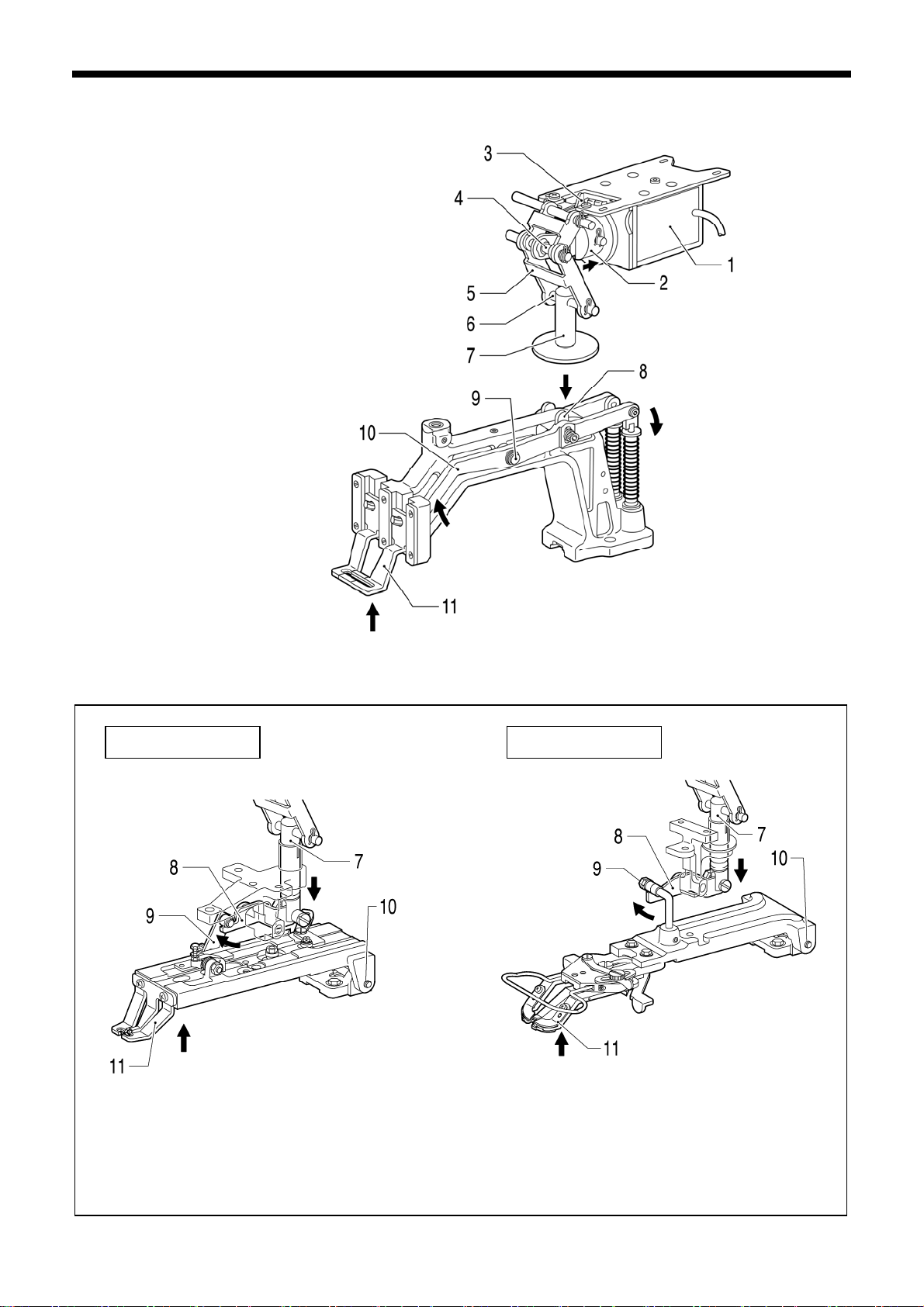
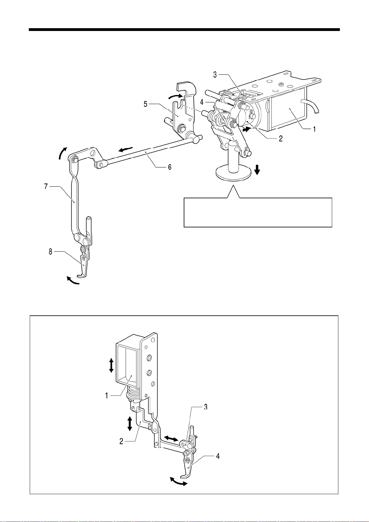
3-14. Work clamp lifter mechanism (Solenoid specifications)
KE-430B, 431B, 433B, 434B
KE-430C, 431C, 434C
l cap
11. Oi
12. Snap pin
13. Link shaft, C [Pull out]
14. Work clamp plate
15. Work clamp lifter link-related parts
16. Rubber caps [2 pcs]
17. Screws [2 pcs]
18. Screws [4 pcs]
19. Presser solenoid assy
[Disconnect the harness]
3305Q
Note:
Hold the work clamp plate
when removing link shaft
C, otherwise the work
clamp plate may fall
down.
3307
Q
1. Springs [2 pcs]
Screws [2 pcs]
2.
3. Guide
4. Snap pins [2 pcs]
5. Rubber cap
6. Link shaft, D [Pull out]
7. Set screws [2 pcs: Loosen]
8. Snap pins [2 pcs]
9. Link shaft, A [Pull out]
10. Washers [2 pcs]
Be careful not to drop.
<KE-433B, 434B, 434C>
3306Q
Do not remove,
otherwise the work
clamp will not move
smoothly.
41
KE-430B, 430C series
Page 49

KE-432, 432C
BE-438, 4
38C
3308Q
11. Oil cap
12. Snap pin
13. Link shaft, C [Pull out]
14. Presser lifter link-related parts
15. Set screw [Loosen]
16. Button clamp lever shaft [Pull out]
17. Work clamp lifter lever
[KE-432B, 432C]
Button clamp lifting lever
[BE-438B, 438C]
18. Retaining ring [BE-438B, 438C]
19. Work clamp lifting rod
[Pull downward]
20. Rubber caps [2 pcs]
21. Screws [2 pcs]
22. Screws [4 pcs]
23. Presser solenoid assy
[Disconnect the harness]
Springs [2 pcs]
1.
2. Screws [2 pcs]
3. Guide
4. Snap pins [2 pcs]
5. Rubber cap
6. Link shaft, D [Pull out]
7. Set screw s [2 pcs: Loosen]
8. Snap pins [2 pcs]
9. Link shaft, A [Pull out]
10. Washers [2 pcs]
Be careful not to drop.
<BE-438B, 438C>
3. DISASSEMBLY
Q
3309
KE-430B, 430C series
42
Page 50

3. DISASSEMBLY
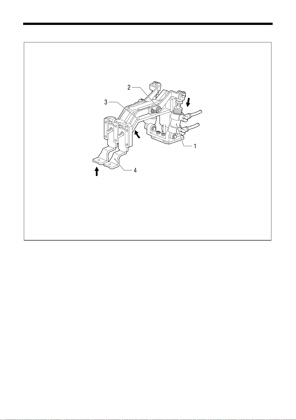
3-15. Stepping foot lifter mechanism (KE-435B, 435C, 436B, 436C)
1. Ret
aining ring
2. Plain washer
3. Screws [4 pcs]
4. Air cylinder setting pl ate
[Pull upward after disconnecting the air tubes]
3310Q
43
KE-430B, 430C series
Page 51

3-16. Thread wiper mechanism
Solenoid specifications
3312
Q
R
emove the thread wiper rod assembly from the
work clamp lever lifter shaft, and then lift it up
together with the thread wiper driving lever to
remove them.
Work clamp lever
lifter shaft
3. DISASSEMBLY
3311Q
1. Screw
2. Plain
washer
3. Thread wiper
4. Retaining ring
5. Set screw [Loosen]
Thread wiper arm assy
6.
[Pull downward]
7. Set screw [Loosen]
8. Thread wi pe r sh aft
9. Retaining ring
10. Tension release lever spring
11. Retaining ring
12. Thread wiper rod assy
13. Thread wiper driving lever
KE-430B, 430C series
44
Page 52

3. DISASSEMBLY
Pneumatic specifications
3313Q
1. Screw with w ashe r
2. Liftin
g lever
3. Plunger pin
4. B o lt s [2 pcs]
5. Solenoid box assy
[Disconnect the harness]
6. Screws [2 pcs]
7. Thread wi pe r co nne cting rod as sy
8. Set screw [Loosen]
9. Thread wiper arm assy [Pull downward]
45
KE-430B, 430C series
Page 53

Stepping foot specifications
KE-484C
3. DISASSEMBLY
3314Q
1. Plunger pin
2.
Bolts [2 pcs]
3. Solenoid box assy
[Disconnect the harness]
4. Set screw [Loosen]
5. Thread wi pe r co nne cting rod as sy
Q
3315
1. Screw
2. B o lt s with washers [2 pcs]
3. B o lt s [2 pcs]
4. Cyli
nder box
[Disconnect the harness]
5. Set screw [Loosen]
6. Thread wi pe r co nne cting rod
KE-430B, 430C series
46
Page 54

3. DISASSEMBLY
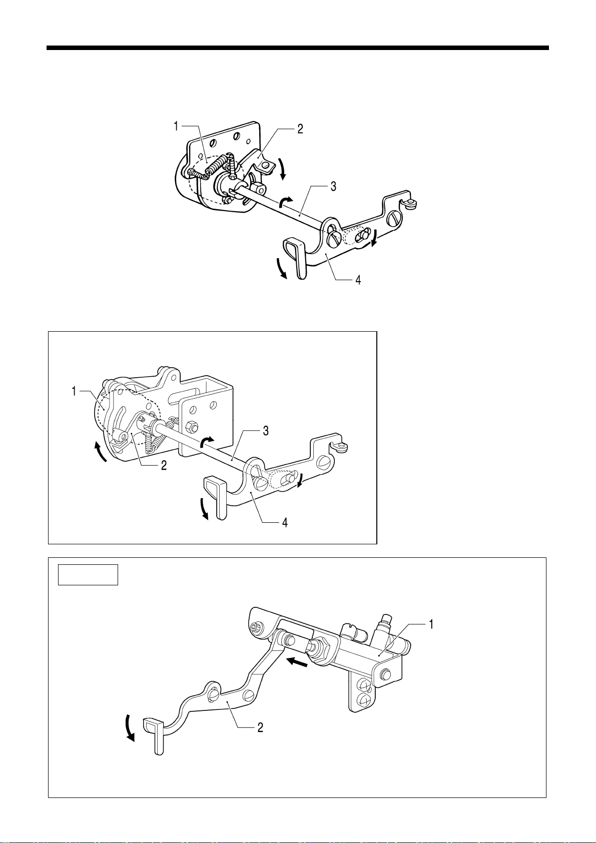
3-17. Thread nipper mechanism
1. Set
screw
2. Thread tension assy [Pull out]
3. Tension release pin
4. Tension release stud
5. Shoulder screw
6. Shoulder screw
7. Tension release rod assy
8. Driving lev er push lever
9. Set screw [Loosen]
10. Work clamp lever lifter shaft
11. Collar
12. Tension release lever
13. Screw with washer
14. Lifting lever
15. Screw [KE-434B, 434C Pneumatic spec.]
16. Tension release rod [KE-434B, 434C Pneumatic spec.]
17. Presser bar lifter crank
3316Q
47
KE-430B, 430C series
Page 55

Stepping foot specifications
KE-484C
3. DISASSEMBLY
3317
1. Set screw
2. Thread tension assy [Pull out]
3. Tension release pin
4. Tensio n release pin, L
5. Shoulder screw
6. Shoulder screw
7. Tension release rod assy
8. Driving lev er push lever
9. Screw
10. Tension release bracket
3318Q
1. Set screw
2. Thread tension assy [Pull out]
3. Tension release pin
4. Tensio n release pin, L
5. Tensi on release cylinder assy
6. Rubber cap
7. Set screw [Loosen]
8. Lever shaft
9. Tensio n release pin push leve r
Q
KE-430B, 430C series
48
Page 56

3. DISASSEMBLY
3-18. Thread take-up mechanism
3319Q
Stepping foot specifications
1. Screws [2 pcs]
2. Solenoid setting plate
3. Spring
4. Set screw s [2 pcs: Loosen]
5. Solenoid joint
6. Screw
7. Spring washer
8. Plain washer
9. Nut
10. Shoulder screws [2 pcs]
11. Thread take-up lever
12. Retaining ring
13. Thread take-up lever crank
14. Plain washer
3320
Q
49
KE-430B, 430C series
Page 57

KE-484C
3. DISASSEMBLY
3321Q
1. Pin
2. Screws [2 pcs]
3. Setting plate
4. Shoulder screws [2 pcs]
5. Thread take-up lever
KE-430B, 430C series
50
Page 58

3. DISASSEMBLY
3-19. Thread trimmer mechanism
Return the machine head to its normal
sition, and then remove the
po
connecting rod lever assembly and the
thread driving lever assembly.
Tilt the machine head.
Be careful not to drop.
3323Q
Be careful not to drop.
3322Q
1. Rubber cap
2
. Set screw [Loosen]
3. Lever shaft
bber cap
4. Ru
5. Set screw [Loosen]
6. Retaining ring
7. Driving lever gui de shaft
[Pull out]
8. Cu
shion
9. Thread release driving lever
assy
10. Washer
11. Spring
12. Spring
13. Spring hook
14. Nuts [2 pcs]
15. Shoulder screws [2 pcs]
16. Washers [2 pcs]
17. Set screw [Loosen]
18. Thread trimmer lever shaft
19. Thread trimmer lever
20. Connecting rod lever assy
21. Thread driving lever assy
51
KE-430B, 430C series
Page 59

KE-484C
Be careful not to drop.
Return the machine head to
its normal position, and then
remove the thread trimmer
rod L and the thread driving
lever assembly.
Tilt the machine head.
3325Q
3. DISASSEMBLY
3324Q
1. Rubber cap
2. Set screw [Loosen]
3. Lever shaft
4. Rubber cap
5. Set screw [Loosen]
6. Ret aining rings [2 pcs]
7. Driving lever gui de shaft
[Pull out]
8. Cushion
9. Wa
sher
10. Spring
11. Spring
12. Bolts [2 pcs]
13. Thread trimmer cylinder
14. Nuts [2 pcs]
15. Shoulder screws [2 pcs]
16. Washers [2 pcs]
17. Set screw [Loosen]
18. Thread trimmer lever shaft
19. Thread trimmer lever
20. Thread trimmer rod, L
21. Thread driving lever assy
KE-430B, 430C series
52
Page 60

3. DISASSEMBLY
53
KE-430B, 430C series
Page 61

4. ASSEMBL Y
Assemble each part in order of the numbers.
grease to the required places when reassembling the parts and once ever y two years.
Apply
4-1. Thread trimmer mechanism (1)
Install the retaining ring between the thread
release driving lever assembly and the
washer.
Pla
ce the cushion against the edge of the
arm, set the various parts so that there is no
gap between them as shown in the
illustration, and then tighten the set screw as
far as the screw stop.
Adjust the position of the thread driving lever
assembly while referring to “5-20. Adjusting
the position of the thread trimming link
mechanism”.
3328Q
Tighten the set screw on the screw flat while
lightly pressing the lever shaft downward.
Apply grease.
Tilt the machine head.
Apply grease.
3330Q
Tighten the set screw on the screw flat while lightly
pressing the thread trimmer lever shaft upward.
Apply grease.
Apply grease.
Driving lever guide shaft
1.
2. Spri
3. Washer
4. Thread rel ea se driving lev er assy
5. Thread drivi n g lever assy
6. Cushion
7. Retaining ring
8. Set screw
9. Rubber cap
10. Connecting rod lever assy
11. Lever shaft
12. Set screw
13. Rubber cap
14. Thread trimmer lever
15. Thread trimmer lever shaft
(with washer and retaining ring)
16. Set screw
17. Thread trimmer rod assy
18. Shoulder screw
19. Nut
20. Washers [2 pcs]
21. Sh
22. Nut
23. Spring hook
24. Spring
4. ASSEMBL Y
3329Q
ng
oulder screw
KE-430B, 430C series
54
Page 62

4. ASSEMBL Y
KE-484C
Install the retaining ring between the thread
driving lever assembly and the washer.
ce the cushion against the edge of the
Pla
arm, set the various parts so that there is no
gap between them as shown in the
illustration, and then tighten the set screw as
far as the screw stop.
Adjust the position of the thread driving lever
assembly while referring to “5-20. Adjusting
the position of the thread trimming link
mechanism”.
3331Q
Tighten the set screw on the screw flat while
lightly pressing the lever shaft downward.
Apply grease.
Tilt the machine head.
Apply grease.
3333Q
Tighten the set screw on the screw flat while lightly
pressing the thread trimmer lever shaft upward.
3332Q
Apply grease.
Apply grease.
1. Driving lever gui de shaft
2. Spring
3. Washer
4. Thread drivi n g lever assy
5. Cushion
6. Ret aining rings [2 pcs]
7. Set screw
8. Rubber cap
9. Thread trimmer rod, L
10. Lever shaft
11. Set screw
12. Rubber cap
13. Thread trimmer lever
14. Thread trimmer lever shaft
(with washer and retaining ring)
15. Set screw
16. Thread trimmer rod assy
17. Shoulder screw
18. Nut
19. Washers [2 pcs]
20. Shoulder screw
21. Nut
22. Thread trimmer cylinder
23. Bolts [2 pcs]
24. Spring
55
KE-430B, 430C series
Page 63

4-2. Thread nipper mechanism
Solenoid specifications
After installing the lifting lever,
check that it moves smoothly.
3334Q
Apply grease.
4. ASSEMBL Y
Apply grease.
Driving lever
stopper
Install the driving lever push lever
an
d the tension release lever U to
the driving lever stopper with the
shoulder screw.
1. Presse r ba r lifter cran k
2. Liftin
g lever
3. Screw with w ashe r
4. Work clamp lever lifter shaft
5. Tensi on release lever
6. Collar
7. Tension release rod assy
8. Shoulder screw
9. Driving lev er push lever
10. Tension release lever, U
11. Shoulder screw
KE-430B, 430C series
56
Page 64

4. ASSEMBL Y
Pneumatic specifications
After installing the lifting
lever
, check that it moves
smoothly.
3335Q
3336Q
Tighten the set screw while lightly
pressing the work clamp lever lifter
shaft.
Apply grease.
Install the driving lever push lever
and the tension release lever U to
the driving lever stopper with the
shoulder screw.
Apply grease.
Driving lever
stopper
Adjust the thread take-up spring height
while referring to “1-2. Standard thread
tension”.
1. Presse r ba r lifter cran k 12. Retaining ring
2. Tension release rod 13. Tension release rod assy
3. Screw 14. Shoulder screw
4. Lifting lever 15. Driving lever push lever
5. Screw with w ashe r 16. Tension release lever, U
6. Work clamp lever lifter shaft 17. Shoulder screw
7. Tensi on release lever 18. Tension release stud
8. Collar 19. Tension release pin
9. Retaining ring 20. Thread tension assy
10. Set screw
21. Set screw
11. Tension release lever spring
57
KE-430B, 430C series
Page 65

Stepping foot specifications
sion release bracket
1. Ten
2. Screw
3. Tension release rod assy
4. Shoulder screw
Driving lever push lever
5.
6. Tensi on release lever, U
. Shoulder screw
7
Tension release pin, L
8.
9. Tension release pin
10. Thread tension assy
11. Set screw
KE-484C
3338Q
Apply sealant (Threebond 1212 or similar) to the
thread sec
Apply grease.
tion.
Adjust the thread take-up spring height
wh
ile referring to “1-2. Standard thread
tension”.
1. Tensio n release pin push leve r
2. Leve
3. Set screw
4. Rubber cap
5. Tension release cylinder assy
6. Tensio n release pin, L
7. Tension release pin
8.
9. Set screw
4. ASSEMBL Y
Apply grease.
Driving lever stopper
Install the driving
lever
push lever
and the tension
release lever U to
the driving lever
stopper with the
shoulder screw.
r shaft
Thread tension assy
3337Q
KE-430B, 430C series
58
Page 66

4. ASSEMBL Y
4-3. Thread wiper mechanism
Solenoid specifications
hten the set screw while lightly
Tig
pressing the work clamp lever lifter
shaft.
3341Q
Adjust the thread take-up spring height while
referring to “1-2. Standard thread tension”.
After installing the thread wiper, moved the forked
part of the thread wiper driving lever and check
that the thread wiper unit moves smoothly.
Not
e:
If the thread wiper unit does not move smoothly,
error E-60 may be displayed.
3339Q
Adjust while referring to “5-17. Adjusting the
thread wiper”.
Thread wiper rod assy
1.
[Insert from above]
2. Thread wi pe r drivin g lever
3. Thread wiper shaft (with washer and
retaining ring)
4. Set screw
5.
Thread wiper rod assy
[Place onto the work clamp lever lifter
shaft]
6. Retaining ring
7. Work clamp lever lifter shaft
8. Set screw
9. Tension release lever spring
10. Retaining ring
11. Thread wiper arm assy
12. Retaining ring
13. Set screw [Temporarily tighten]
14. Thread wiper
15. Plain washer
16. Screw
17. Tension release stud
18. Tension release pin
19. Thread tension assy
20. Set screw
59
KE-430B, 430C series
Page 67

Pneumatic specifications
When installing the sole-
d box assembly, pass
noi
the tension release rod
through the hole.
3342Q
After i
nstalling the plunger pin, push
the thread wiper connecting rod
assembly up and check that the thread
wiper unit moves smoothly.
4. ASSEMBL Y
Adjust while referring to “5-17.
Adjusting the thread wiper”.
1.
Thread wiper arm assy
2. Set screw [Temporarily tighten]
3. Thread wi pe r co nne cting rod as sy
4. Screws [2 pcs]
5. Solenoid box assy
6. Washers [2 pcs]
7. B o lt s [2 pcs]
8. Plunger pin
9. Lifting lever
10. Screw with washer
KE-430B, 430C series
60
Page 68

4. ASSEMBL Y
Stepping foot specifications
After installing the face pl
install the bolts, and then push the thread wiper connecting
rod assembly up and check that the thread wiper unit moves
smoothly.
ate while referring to “4-21. Covers”,
KE-484C
3343Q
Adjust while referring to “5-17.
sting the thread wiper”.
Adju
1. Thread wi pe r co nne cting rod as sy
2.
Set screw [Temporarily tighten]
3. Solenoid box assy
4
. Washers [2 pcs]
Bolts [2 pcs]
5.
6. Plunger pin
7. Bolts [ 2 pcs: Install to face plate]
3344Q
1.
Thread wiper connecting rod
2. Set screw [Temporarily tighten]
3. Cylinder box
4. Washers [2 pcs]
5. B o lt s [2 pcs]
6. B o lt s with washers [2 pcs]
7. Screw
61
KE-430B, 430C series
Page 69

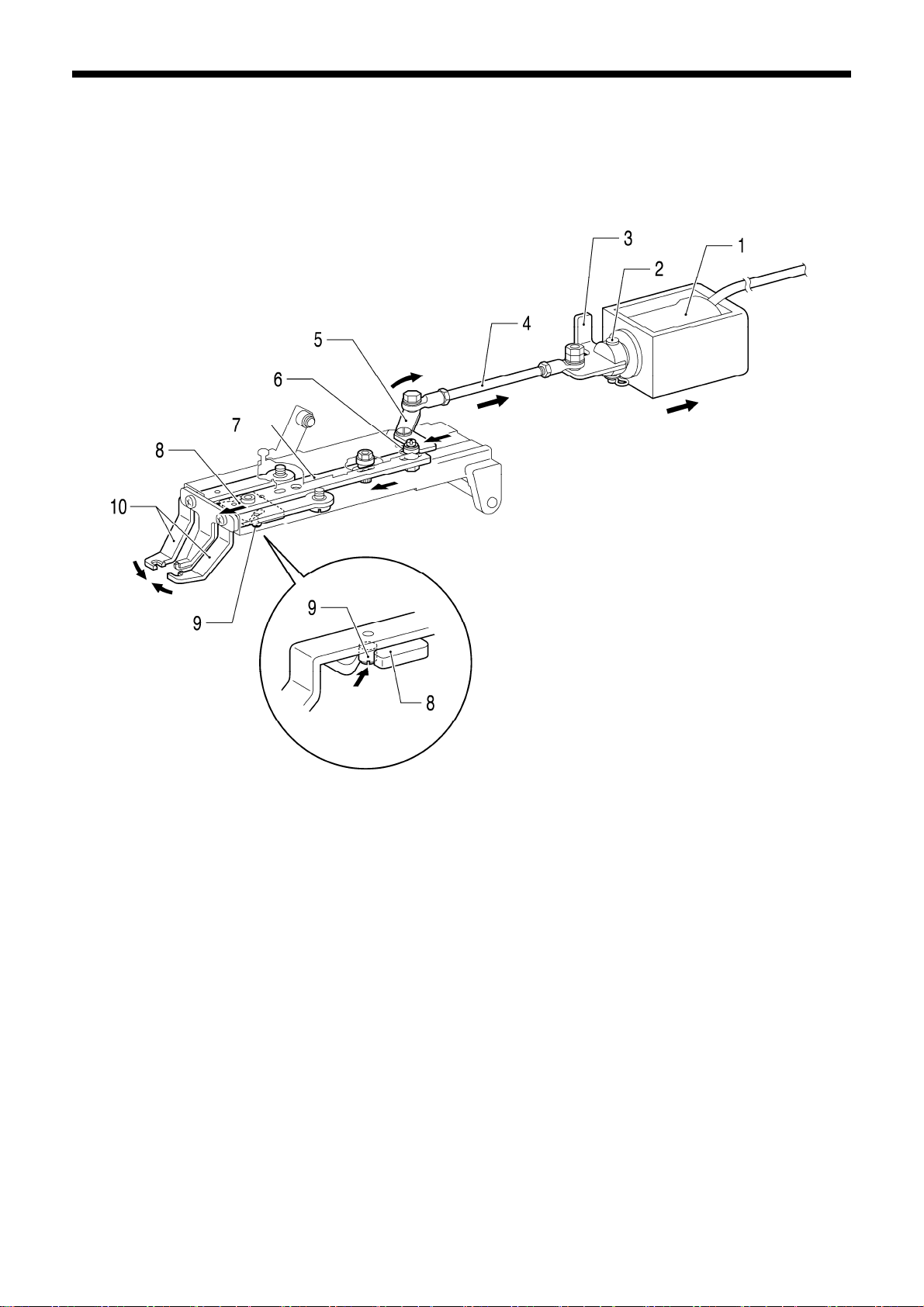
4-4. Thread take-up mechanism
3346Q
While pushing the solenoid joint
in the direction of the arrow, set
the solenoid setting plate and the
solenoid joint so that the gap
between them is 0.5 mm, and
then tighten the set screws.
* Move the solenoid joint and
check that the thread take-up
lever operates smoothly. If it
does not move smoothly, it
may damage the solenoid. If
the movement is not smooth,
make fine adjustments to the
position of the solenoid setting
plate until the thread take-up
lever operates smoothly.
Seen from the front
3345Q
Attach the spring to spring
ho
oks (A) and (B).
1) Provisionally install the solenoid
joint to the thread take-up solenoid
with the set screws.
2) Place the solenoid joint onto the
thread take-up lever crank so that
the flat surface is against the flat
part of the thread take-up crank,
and then install the solenoid setting
plate to the machine head.
Apply grease.
3347Q
Thread take-up lever crank
1.
2. Plain washer
3. Retaining ring
4. Thread take-up lever
5. Shoulder screws [2 pcs]
6. Set screw [Temporarily tighten]
7. Spring washer
8. Plain washer
9. Nut
10. Solenoid joint
11. Set screws [2 pcs]
12. Spring
13. Solenoid setting plate
14. Screws [2 pcs]
4. ASSEMBL Y
KE-430B, 430C series
62
Page 70

4. ASSEMBL Y
p
Stepping foot specifications
3346Q
While pushing the solenoid joint
in the direction of the arrow, set
the solenoid setting plate and the
solenoid joint so that the gap
between them is 0.5 mm, and
then tighten the set screws.
* Move the solenoid joint and
check that the thread take-up
lever operates smoothly. If it
does not move smoothly, it
may damage the solenoid. If
the movement is not smooth,
make fine adjustments to the
position of the solenoid setting
plate until the thread take-up
lever o
erates smoothly.
Attach the spring to spring
hooks (A) and (B).
1) Provisionally install the solenoid
joint to the thread take-up solenoid
with the set screws.
2) Place the solenoid joint onto the
thread take-up lever crank so that
the flat surface is against the flat
part of the thread take-up crank,
and then install the solenoid setting
plate to the machine head.
Apply grease.
3349Q
1.
Thread take-up lever crank
2. Plain washer
3. Retaining ring
4. Thread take-up lever
5. Shoulder screws [2 pcs]
6. Set screw [Temporarily tighten]
7. Spring washer
8. Plain washer
9. Nut
10. Solenoid joint
11. Set screws [2 pcs]
12. Spring
13. Solenoid setting plate
Seen from above 14. Screws [2 pcs]
3348Q
63
KE-430B, 430C series
Page 71

KE-484C
4. ASSEMBL Y
3350Q
1. Thread take-up lever
2. Shoulder screws [2 pcs]
3. Setting plate
4. Screws [2 pcs]
5. Pin
6. Retaining ring
KE-430B, 430C series
64
Page 72

4. ASSEMBL Y
4-5. Work clamp lifter mechanism (Solenoid specifications)
When assembling, apply grease to the required places while referring to “4-5-1. Applying grea se”.
KE-430B, 431B, 433B, 434B
KE-430C, 4
1.
Work clamp lifter link-related parts [Insert from above the arm]
2. Link shaft, B [Place into the forked section of the thread wiper driving lever (2)]
3. Link shaft, A [Pass through the washer and link A (3)]
4.
Snap pins [2 pcs: Attach to both ends of link shaft A]
5. Set screws [2 pcs]
6
. Work clamp lifter stopper rubber
7. Work clamp plate [Insert from below the arm]
8. Link shaft, C [Pass through link B (8) and the work clamp plate]
9. Snap pins [2 pcs: Attach to both ends of link shaft C]
10. Presser solenoid assy [Insert from above the arm]
31C, 434C
Secure link shaft, A using the set
scre
w so that link, B (8) is centered
in the bush.
<KE-433B, 434B, 434C>
3351Q
65
KE-430B, 430C series
Page 73

3352Q
Lastly, move the work clamp lifer link-related parts by
hand and check that they move smoothly.
11. Screws [2 pcs]
12. Screws [4 pcs]
13. Rubber caps [2 pcs]
14. Link shaft, D
15. Snap pins [2 pcs]
16. Guide
17. Screws [2 pcs]
18. Springs [2 pcs: Hook onto link shaft B and the grooved pins (18)]
19. Oil cap
20. Rubber cap
4. ASSEMBL Y
Tighten the screws so that the
presser solenoid assembly protrudes
by 110.0 ± 0.2 mm from the edge of
the arm.
Seen from above
3353Q
KE-430B, 430C series
66
Page 74

4. ASSEMBL Y
Wh
en assembling, apply grease to the required places while referring to “4-5-1. Applying grease”.
KE-432B, 432C
BE-438B, 4
38C
Secure link shaft A using the set
scre
w so that link B (10) is centered
in the bush.
<BE-438B, 438C>
1. Work clamp lifter link-related parts
[Insert from above the arm]
2. Link shaft, B
[Place into the forked section of the thread wiper driving lever (2)]
3.
Link shaft, A [Pass through the washer and link A (3)]
4. Snap pins [2 pcs: Attach to both ends of link shaft A]
5. Set screws [2 pcs]
6. Retaining ring
7. Plain washer
8. Rubber band
9. Work clam p lifting rod
10. Link shaft, C [Pass through link B (10) and the work clamp plate]
11. Snap pins [2 pcs: Attach to both ends of link shaft C]
12. Presser solenoid assy [Insert from above the arm]
13. Screws [2 pcs]
14. Screws [4 pcs]
15. Rubber caps [2 pcs]
3354Q
67
KE-430B, 430C series
Page 75

3355Q
Lastly, move the work clamp lifer link-related parts by
hand and check that they move smoothly.
16. Link shaft, D
17. Snap pins [2 pcs]
18. Guide
19. Screws [2 pcs]
20. Springs [2 pcs: Hook onto link shaft B and the grooved pins (20)]
21. Oil cap
22. Rubber cap
23. Work clamp lifter lever[KE-432B, 432C]
Button clamp lifting lever[BE-438B, 438C]
24. Button clamp lever shaft
25. Set screw
4. ASSEMBL Y
Tighten the screws so that the
presser solenoid assembly protrudes
by 110.0 ± 0.2 mm from the edge of
the arm.
en from above
Se
3356Q
KE-430B, 430C series
68
Page 76

4. ASSEMBL Y
4-5-1. Applying grease
If the work clamp does not move up and down smoothly, error E-60 may be displayed.
Check that the mechanism moves smoothly and also apply grease to all sliding parts during assembly.
-433B, 434B, 434C>
<KE
<KE-432B, 432C> <BE-438B, 438C>
Sliding portions of link shaft, C [1], link, B [2], and work clamp plate (work clamp lifting rod: KE-432B, 432C,
1.
BE-438B, 438C) [3]
2. Sliding portions of link shaft, B [4], link, B [2], link, A [5] and link assy, C [6]
3. Forked portion of the thread wiper driving leve r [7]
4. Sliding portions of link shaft, A [8] and link, A [5]
5. Slidi ng portions of link shaft, D [9] and link a ssy, C [6]
6. Forked portion of the plunger [10] where lin k assy, C [6] is fitted
7. Outer and inner surfaces of sphe rical bush [11] to be attached to link assy, C [6]
8. Shaft of work clamp pl ate (wor k cla mp lif ting rod: KE-432B/432C, BE-438B/438C) [3]
3357Q
69
KE-430B, 430C series
Page 77

4-6. Feed mechanism (1)
KE-430B, 431B, 432B, 433B, BE-438B
KE-430C, 431C, 432C, BE-438C
Fee
d cams X and Y both have index marks. Check these when using.
Assembly steps of the feed mechanism are the same for X and Y directions.
Tighten the set screw in the
illustration at the screw stop
position.
Set screw at screw stop
Ch
eck that the feed cam
turns smoothly.
3361Q
Place the coupling hub
onto the pulse motor shaft,
and then tighten the set
screw at the screw stop
position so that the pulse
motor shaft protrudes from
the edge by 2.5 mm.
3359Q
Place coupling hub 8 onto
the cam shaft so that there
is no play in the hub, and
then tighten the set screw
at the screw stop position
as shown in the illustration.
3362
Q
4. ASSEMBL Y
3358Q
Screw stop
Q
3360
1. Feed cam
. Ball bearings [2 pcs]
2
3.
Cam shaft (with retaining ring)
4.
Coupling hub, 8
5. Set screws [2 pcs]
Set screws [2 pcs]
6.
7. Feed home position dog
8. Screw [Provisionally tighten at
middle of slot]
9. Coupling hub, 6.35
Coupling hub, 8[KE-433B]
10. Set screws [2 pcs]
KE-430B, 430C series
70
Page 78

4. ASSEMBL Y
Assembly steps of the feed mechanism are the sam e for X and Y directions.
Apply grease.
Apply grease.
Apply grease.
Plac
coupling hub 8.
3363Q
Place the feed cam bracket onto the positioning
pin
s, and then install with the screws.
Set the coupling hub at the angle for inserting the
coupling spacer, and install the pulse motor to the
machine bed.
* Make sure that the harness faces correctly.
3365Q
3365Q
Q
3364
e the coupling spacer onto
11. Coupling spacer
sitioning pins [2 pcs]
12. Po
13. Feed cam bracket
14. Screws [2 pcs]
3366Q
15. Pulse motor assy, X
16. Bolts [4 pcs]
17. Pu
lse motor assy, Y
18. Bolts [4 pcs]
71
KE-430B, 430C series
Page 79

KE-434B, 435B, 436B
KE-434C, 435C, 436C, 484C
d cams X and Y both have index marks. Check these when using.
Fee
Assembly steps of the feed mechanism are the same for X and Y directions.
X direction
Place the cam onto the cam
shaft so that there is no play in
the cam, and then tighten the
set screws.
3369Q
Place the coupling hub 8
onto the pulse motor shaft,
and then tighten the set
screw at the screw stop
position so that the pulse
motor shaft protrudes from
the edge by 2.5 mm.
3362Q
4. ASSEMBL Y
Align the edges of coupling
hub 8 and the cam shaft.
3368Q
Y direction
1.
Coupling hub, 8
2.
Set screws [2 pcs]
3. PM bracket
4. Ball bearing [X: 2 pcs, Y: 1 pc]
5. Cam shaft
6. Feed cam
7. Set screws [2 pcs]
8. Coupling hub, 8
9. Set screws [2 pcs]
3367
Q
KE-430B, 430C series
72
Page 80

4. ASSEMBL Y
Apply grease.
While pressing the set collar,
tighten the set screw at the
screw stop position.
Place the feed cam bracket
onto the positioning pins, and
then install with the screws.
3371Q
Apply grease.
1) Place the coupling spacer onto coupling hub 8.
2) Set coupling hub 8 on the pulse motor shaft at the
Apply grease.
angle for inserting the coupling spacer, and install
the pulse motor to the machine bed.
* Make sure that the harness faces correctly.
3370Q
10. Ball bearing [Insert into the bed]
11. Coupling spacer
12. Pulse motor assy, X
13. PM bracket, X
14. Bolts [4 pcs]
15. Positioning pins [2 pcs]
16. Y-feed cam bracket
17. Screws [2 pcs]
18. Ball bearing
19. Coupling spacer
20. Pulse motor assy, Y
21. PM bracket, Y
22. Bolts [4 pcs: 3 pcs for KE-484C]
23. Set screw collar
24. Set screws [2 pcs]
73
KE-430B, 430C series
Page 81

4-7. Feed mechanism (2)
4. ASSEMBL Y
KE-430B, 431B, 432B, 433B, BE-438B
KE-430C, 4
31C, 432C, BE-438C
Feed home
posit
ion dog
O
il supply
hole
3372Q
Note:
Mak
e sure the wick does not
touch the connecting rod lever.
1) Insert the tack width feed lever shaft with the
thrust washer and retaining ring installed into
the Y-feed lever assembly, press down on
the top of it so that there is no play, and then
tighten the set screw at the screw stop
position.
*
Check that the Y-feed lever assembly
moves smoothly.
Q
3375
2) Put the driver into the
en
d of the Y-feed lever,
and press the X-feed
lever assy downward.
3)
Place the set screw
collar on the shaft of
the X-feed lever, press
it in the direction of the
arrow, and tighten the
set screws.
3376Q
Push the home position
sensor Y cable into the
recess.
Install home position sensors X and
Y so that there is a
gap of 0.5–0.9 mm
between the sensors and the feed
home position dog.
3374
Q
Q
3373
Feed home
ion dog
posit
1. X-feed lever assy [Insert onto bushing]
d cam roller
2. Fee
[Place into groove
of feed cam X]
3. Thrust washer
4. Y-feed lever assy
d cam roller
5. Fee
[Place into groove
of feed cam Y]
6. Thrust washer
7. Tack width feed lever shaft (with retaining
ring)
8. Set screw
9. Set screw collar
10. Set
screws [2 pcs]
11. Home sensor setting plate
12. Screw
13. Home sensor setting plate
14. Screw
15. Cord holder
16. Screw
17. Cord holder
18. Screw
19. Wick [Insert into oil supply hole]
20. Wick [Insert into oil supply hole]
KE-430B, 430C series
74
Page 82

4. ASSEMBL Y
KE-434B, 435B, 436B
KE-434C, 4
35C, 436C, 484C
Oil supply
hole
3377Q
1) Insert the tack width feed lever shaft with the
thrust washer and retaining ring installed into
the Y-feed lever assembly, press down on
the top of it so that there is no play, and then
tighten the set screw at the screw stop
position.
* Check that the Y-feed lever assembly
moves smoothly.
Note:
Make sure the wick does not
touch the connecting rod lever.
3575Q
2) Put the driver into the
end of the Y-feed lever,
and press the X-feed
lever assy downward.
3) Place the set screw
collar on the shaft of
the X-feed lever, press
it in the direction of the
arrow, and tighten the
set screws.
3376
Q
Push the home position
sensor Y cable into the
recess.
Home position
dog, X
3379Q
Home position
sensor X
Install the X-sensor setting base so that
there is a gap of 0.5–0.9 mm between the
sensing surface of home position sensor X
and the home position dog X.
3378Q
1. X-feed lever assy [Insert onto bushing]
2. Feed cam roller
[Place into groove of feed cam X]
3. Thrust washer
4. Y-feed lever assy
5. Feed cam roller
[Place into groove of feed cam Y]
6. Thrust washer
7. Tack width feed lever shaft (with retaining
ring)
8. Set screw
9. Set screw collar
10. Set screws [2 pcs]
11. X-sensor setting base
12. Screw
13. Y-sensor setting plate
14. Screw
15. Cord clamps [3 pcs]
16. Screws [3 pcs]
17. Wick [Insert into oil supply hole]
18. Wick [Insert into oil supply hole]
75
KE-430B, 430C series
Page 83

4-8. Upper shaft mechanism
Place the thread take-up crank onto the upper
shaft from the face plate end, tighten the
screw into the hole in the upper shaft, and
then tighten the set screw.
3381Q
3382Q
<KE-435B, 435C>
<
KE-436B, 436C>
Apply grease. Apply grease.
Make a gap of 1.0 mm between
the magnet of timing pulley
assembly U and the synchronizer assembly, and then
align the rear set screw in the
rotation direction of timing pulley
assembly U with the screw stop
position and tighten the set
screw at that position.
Rotation direction
Apply grease.
Upper shaft bu
Place the thread take-up crank, thrust
wa
(stepping foot connecting rod) into the
upper shaft bush so that there is no play
in the parts, and then tighten the set
screw at the screw stop position.
Rotation direction
4. ASSEMBL Y
Push the t
hread trimmer
cam onto the upper shaft
crank, align the forward set
screw in the rotation
direction with the screw
stop position, and tighten
the set screw at that
position.
Apply adhesive (Threebond
sh
14
01 or similar) to the outside
of the bearing.
sher and bobbin winder pulley
1. Upper shaft
2. Thread trimmer cam
3. Bobbin winder pulley
<3> Stepping foot
connecting rod
Thrust washer
4.
read take-up crank
5. Th
6. Screw
screw
7. Set
Set screws [2 pcs]
8.
<8> Set screws [2 pcs]
9. Set screws [2 pcs
10. Synchronizer assy
11. Screws [2 pcs]
12. Timing pulley assy, U
3383Q
13. Set screws [2 pcs]
3380Q
KE-430B, 430C series
76
Page 84

4. ASSEMBL Y
KE-484C
Make a gap of 3 mm
between the thread trimmer
cam and U-timing pulley F.
Align the ridge line at the back
of the groove in the upper
shaft with the edge of the
thread trimmer cam.
Apply grease.
Place the thread take-up crank onto the
upper shaft from the face plate end,
tighten the screw into the hole in the
upper shaft, and then tighten the set
screw.
3385Q
Upper shaft
bush
Apply adhesive (Threebond
3384Q
1401 or similar) to the outside of
the bearing.
Apply grease.
Place the thread take-up crank, thrust
asher and bobbin winder pulle y into the
w
upper shaft bush so that there is no play
in the parts, and then tighten the set
screw at the screw stop position.
per shaft 11. Set screws [2 pcs]
1. Up
2. Thread trimmer cam 12. Set screws [2 pcs]
3. U-timing pulley, F 13. Tension pulley arm
4. U-timing belt, F 14. Adjusting screw
5. Bobbin winder pulley 15. Nut
6. Thrust washer 16. Adjusting screw
7. Thread take-up crank 17. Nut
8. Screw 18. Plain washer
9. Set screw
19. Nut
10. Set screws [2 pcs]
77
KE-430B, 430C series
Page 85

3386Q
3387
4. ASSEMBL Y
20. Setting plate packing
21. Frame side cover
22. Bli
nd plate
23. Screws [4 pcs]
24. Belt cover support pillars [2 pcs]
25. Synchronizer assy
26. Screws [2 pcs]
27. Timing pulley assy, U
28. Set screws [2 pcs]
Q
3382Q
Make a gap of 1.0 mm between
the magnet of timing pulley
Rotation direction
assembly U and the synchronizer assembly, and then
align the rear set screw in the
rotation direction of timing pulley
assembly U with the screw stop
position and tighten the set
screw at that position.
3383Q
KE-430B, 430C series
78
Page 86

4. ASSEMBL Y
4-9. Stepping foot lifter mechanism (KE-435B, 435C, 436B, 436C)
Work clamp
lifter lever
Presser bar bush
3389Q
Install the air cylinder setting plate so that there
is a distance of 42.8–43.3 mm between section
A of the work clamp lifter lever and the top of
the presser bar bush when section A is at its
lowest point.
1. Stepping link, A
2. Plain
washer
3. Retaining ring
4. Air cylinder setting pl ate
5. Screws [4 pcs]
3388Q
79
KE-430B, 430C series
Page 87

4-10. Stepping foot mechanism (KE-435B, 435C, 436B, 436C)
4. ASSEMBL Y
Adjust while referring to
“5
-16. Changing the
work clamp lift”.
Adjust while referring to
“5-15. Work clamp
adjustment”.
Set
the presser adjusting screw so that the distance
from its top to the top of the machine head is
approximately 32 mm, and then secure the nut.
Nut
3391Q
Insert the presser bar spring and the
presser bar spring guide into the top of
the machine head, pass them through
the washer, and then place them onto the
presser bar.
3390Q
1. Stepping foot arm, R
2.
Feed lifter lever shaft
3. Washers [2 pcs]
4. Feed roller
5. Nut
Stepping foot arm, F
6.
7. Bush, L
8. Bush, R
9. Bolt
10. Presser bar [Insert from above]
11. Pr
esser bar lifter
12. Cushion
13. Pre
sser bar clamp
14. Screw
15. Washer
16. Presser bar spring
17. Presser bar spring guide
18. Presser adjusting screw
19. Stepping link assy
20. Screws [2 pcs]
21. Presser foot
2. Finger guard
2
23. Plain washers [2 pcs]
24. Screw
KE-430B, 430C series
80
Page 88

4. ASSEMBL Y
4-10-1. Adjusting the lowest point of the presser foot
Carry out the steps in “4-11. Needle bar mechanism” before making this adjustment.
3506Q 3507Q
Q 3509Q
3508
1.
Loosen the set screw (1).
2. Turn the machine pulley to raise the needle bar from its lowest position until reference line B (the lowest
reference line on the needle bar) or reference line b (second reference line from the top) is aligned with the
lower edge of the needle bar bush (2).
3. Turn the stepping work clamp cam (3) without turning the machine pulley to set the presser bar lifter (4) to its
lowest position, and then secure the stepping work clamp cam (3) to the upper shaft (5) with the set screw (1).
* At this time, push the stepping work clamp cam (3) in the direction of the arrow so that there is no play
between it and the upper shaft (5).
4. With the presser bar lifter (4) at its lowest point, loosen the bolt (8) of stepping work clamp arm R (7) an d
adjust so that the gap between the presser bar lifter (4) and the presser bar bush (6) is 0.5–1.0 mm. (A guide
to this is that the index mark on stepping work clamp arm F (9) should be about aligned with the index mark
on the arm.)
* Check that there is no forward or backward play in stepping work clamp arm F (9) at this time.
5. With the presser bar (10) at its lowest position , secure the presser bar c lamp (11) with the screw (12) so that
the distance from the bottom edge of the presser bar and the top of the needle plate is 23 mm.
Index marks
81
KE-430B, 430C series
Page 89

A
4-11. Needle bar mechanism
Press the thread
take-up support shaft
gently while tightening
the set screw.
After securing the needle bar, position the
ne
edle bar guide so that the machine pulley
turns smoothly, and then tighten the screws.
3394Q
lign the needle bar so that
reference line A (the second
lowest reference line on the
needle bar) or reference line a
(top reference line) is aligned
with the lower edge of the
needle bar bush when the
machine pulley is turned to raise
the needle bar from its lowest
position, and then set the cut
section so that it is facing
forward and tighten the screw.
3395Q
Apply grease.
Cut section
Oil supp
4. ASSEMBL Y
ly hole
Align th
e set screw with
3392Q
the screw stop.
Apply grease.
Apply grease.
Fit the chamfering side of the slide block
into th
e groove on the needle bar guide.
1. Needle bar guide
2. Scre
ws
[2 pcs: Temporarily tighten]
3. Thread take-up lever
4. Needle ba r conne cting ro d
edle bearing
5. Ne
6. Set screw
7. Set
screw
read take-up support
Needle bar
bush
8. Th
9.
Thread take-up support shaft
10. Set
screw
11. Slide block
12. Needle bar clamp
13. Needle bar [Insert from above]
14. Screw
15. Oil cap
16. Rubber caps [4 pcs]
17. Wick [Insert into oil supply
hole]
3393Q
KE-430B, 430C series
82
Page 90

4. ASSEMBL Y
4-12. Lower shaft mechanism
3398Q
KE-430C series
BE-438C
Place the driver against the
retaining ring and provisionally
tighten the bolt.
Apply grease.
Apply grease.
Mating mark
Clamp the rock gear with the stepped part
of the rock gear shaft and the set screw
collar so that there is no play in the rock
gear, and then tighten the set screws.
3396Q
Engage the lower shaft
gear with the rock gear.
Apply grease.
Lower shaft bush
Set the needle bar
to its lowest position
KE-430B series
BE-438B
and then insert the
lower shaft with this
screw stop facing
straight downward.
Clamp the lower shaft bush with the
lower shaft gear and the set screw collar
so that there is no play in the lower shaft
bush, and then tighten the set screws.
Insert the crank rod (lower part) into the crank of the
upper shaft, and then align the mating mark on the
crank rod (upper part) from above and gently tighten
the screws.
* Check that the machine pulley turns smoothly.
1. Rock gear shaft [Insert from the rear of the machine head]
2. Rock gear
3. Set screw collar
4. Set screws [2 pcs]
5. Lower shaft assy [Insert from the rear of the machine head]
6. Set screw collar
7. Set screws [2 pcs]
8. Retaining ring
9. Driver
10. Bolt [Temporarily tighten]
11. Crank rod (Lower part) [Insert into upper shaft crank]
12. Crank rod (Upper part) [Align the mating mark]
13. Screws [2 pcs]
3397
Q
83
KE-430B, 430C series
Page 91

While turning the machine pulley, move the
rock gear to the left and right to find the
position where it moves smoothly. Then
without moving the rock gear, turn the rock
gear shaft so that there is a gap of 0.05--0.12
mm at the end of the driver, and tighten the
set screws.
* Check that the machine pulley turns
smoothly.
3399Q
Carry out the steps in “5-26.
Adjusting the tension of the upper
shaft timing belt” before tightening.
3401Q
4. ASSEMBL Y
3400Q
Place the upper shaft timing
belt onto the upper shaft
pulley and the motor pulley.
14. Set screws [2 pcs]
15. Wick [Pass through the rock gear shaft and make a knot]
16. Upper shaft timing belt
17. Motor bracket
18. Bolts [3 pcs: Temporarily tighten]
19. Bolt
20. Nut
21. Motor connector
KE-430B, 430C series
84
Page 92

4. ASSEMBL Y
KE-484C
3402Q
Carry out the steps in “5-26. Adjus ting
the tension of the upper shaft timing
belt” before tightening.
Place the upper shaft timing belt
onto the upper shaft pulley and the
motor pulley.
3404Q
3403Q
Lower shaft [Insert from the rear of the
1.
machine head]
2. Lower shaft timing pulley
3. Thrust bearing
4. Lower shaft gear spacer
5. Wick [Pass through the lower shaft and
make a knot]
6. Set screw
7. U-timing belt, F
[Place onto the lower shaft timing pulley]
8. Rotary hook shaft
[Insert from the rear of the machine head]
9. Set screw collar
10. Set screws [2 pcs]
11. Lower gear
12. Set screw
13. Upper shaft timing belt
14. Motor bracket
15. Bolts [3 pcs: Temporarily tighten]
16. Bolt
17. Nut
18. Motor connector
85
KE-430B, 430C series
Page 93

A
4-13. Thread trimmer mechanism (2)
4. ASSEMBL Y
1) Place the thread connecting rod onto the
pin of the connecting rod lever assembly,
and then install the needle plate with flat
screws and screws so that the needle is at
the center of the needle hole.
<KE-484C>
3405Q
Connecting rod lever
assy
3406Q
Dr
iving lever
stopper
2) Turn the machine pulley to set the needle to its
lowest position.
Install the thread trimmer solenoid with the
3)
screws so that the gap between the thread
driving lever assembly and the driving lever
stopper is 0.5 mm when the plunger of the
thread trimmer solenoid is pushed all the way
in.
Plunger
Thread driving
lever assy
fter installing, carry out the steps in “5-19. Adjusting the movable knife”.
3408Q
Connecting rod lever
1. Thread co nn ecti ng rod
2. Needle plate
3. Flat screws [2 pcs]
4. Screws [2 pcs]
5. Thread trimmer solenoid
Screws [2 pcs]
6.
3407Q
KE-430B, 430C series
86
Page 94

4. ASSEMBL Y
4-14. Shuttle hook mechanism
3411Q
After installing the shuttle hook, carry out the adjustments in “5-2.
Adjusting the needle bar lift amount”, “5-3. Adjusting the driver needle
guard” and “5-4. Adjusting the needle clearan c e”.
3412Q
1. Needle ba r thre ad gui de
2. Ne
edle
3. Set screw
4. Shuttl
5. Shuttl
e hook
e race base
6. Bobbin
7. Bobbin case assy
. Felt holder
8
9. Support
[Return to original position]
<KE-430B series
, BE-438B>
3447Q
1) Place the felt support as shown in the
illustration so as not to clamp the felt.
Felt
87
2) Press the felt and the wick gently as shown in
the illustration.
KE-430B, 430C series
Wic
k
Felt
3419
3421Q3420Q
Q
Page 95

KE-484C
3422Q
Inst
distance from the tip of the bobbin case holder
position bracket to the needle drop surface is
approximately 0.8 mm.
Tu
rn the machine pulley to align the tip of the rotary hook with
the needle center line. Then tighten the set screw to adjust the
clearance between the needle and the tip of the rotary hook to
0.01–0.08 mm.
Tip of the rotary hook
Set s
crews
4. ASSEMBL Y
3423
Approx. 0.8mm
Bobbin case hold
ion bracket
posit
Shuttle h
er
ook
all the hook stopper setting base so that the
3424Q
3425Q
1. Needle ba r thre ad gui de
edle
2. Ne
3. Set screw
4. Treble hook assy
Set screws [2 pcs]
5.
Hook stopper setting base
6.
7. Screw
8. Bobbin
9. Bobbin case assy
Q
KE-430B, 430C series
88
Page 96

4. ASSEMBL Y
4-15. Work clamp arm mechanism (KE-430B, 430C, 431B, 431C)
Be careful not to drop these two ball
bearings when installing the feed bracket
assembly.
Align with the screw stop and push down
from above while tightening the set screw.
3426Q
Tack length feed
slide block
Place the tack length feed slide block
into the groove of the feed bracket
assembly, and then use the screws to
install it together with the feed bracket
guide plate.
Be careful not to drop these three
ball bearings when installing the
work clamp arm assembly.
Secure the work clamp arm support shaft with the set screw so
e bottom of the work clamp arm support plate and the ball
that th
bearings touch when the work clamp is rai se d.
Refer to “4-20. Work clamp
arm mechanism (Applying
grease)”
3427Q
Carry out the adjustment in “5-24. Adjusting the
home position” before installing the fee d plate.
d bracket assy
1. Fee
2. Feed bracket guide plat e
3. Screws [8 pcs]
4. Rod end
5. Tack width feed shaft
6. Set screw
7. Rubber cap
8. Feed plate
9. Screws [2 pcs]
10. Work clamp felt
11. Work clamp arm assy
12. Washers [2 pcs]
13. Bolts [2 pcs]
14. Work clamp arm support shaft
15. Set screw
After installing, carry out test feed ing and check that the needle hole is inside the work clamp and the
feed plate frame. If the needle hole is not inside the frame, adjust the position of the work clamp arm
assembly and feed plate.
89
KE-430B, 430C series
Page 97

4. ASSEMBL Y
4-16. Work clamp arm mechanism (KE-432B, 432C)
Be careful not to drop these two ball
bearings when installing the feed bracket
assembly.
3426Q
Tack length feed
slide block
First place onto A, then insert into B
d place onto C.
an
Carry out the adjustment in “5-24. Adjusting the home
position” before installing the feed plate.
After installing, carry out test feed ing and check that the needle hole is inside the work clamp and the
feed plate frame. If the needle hole is not inside the frame, adjust the position of the button clamp holder
support and feed plate.
Align with the screw stop and push down
from above while tightening the set screw.
Place the tack length feed slide
block into the groove of the feed
bracket assembly, and then use
the screws to install it together
with the feed bracket guide plate.
Refer to “4-20. Work clamp arm
mechanism (Applying grease)”
d bracket assy
1. Fee
2. Feed bracket guide plat e
3. Screws [8 pcs]
4. Rod end
5. Tack width feed shaft
6. Set screw
7. Rubber cap
8. Feed plate
9. Screws [2 pcs]
10. Work clamp felt
11. Button clamp holder
support
12. Plain washers [2 pcs]
13. Bolts [2 pcs]
14. Work clamp arm assy
15. Button clamp holder shaft
16. Set screws [2 pcs]
17. Nuts [2 pcs]
Adjusting screw
Co
mpression spring
18. Work clamp carrier rod assy
3428Q
19. Washer
20. Bolt
KE-430B, 430C series
90
Page 98

4. ASSEMBL Y
y
4-17. Work clamp arm mechanism (KE-433B)
Install parts 1 to 6, clamp them using
parts 7 and 8 so there is no play in them,
and tighten the set screw 9.
Note:
Install so that the two ball bearings of
the feed bracket guide shaft assembly
do not fit into the holes in the feed
bracket guide plate.
Be careful not to d
ball bearings when installing the
work clamp arm assembl
Secure the work clamp
arm support shaft with the
set screw so that the
bottom of the work clamp
arm support plate and the
ball bearings touch when
the work clamp is raised.
3430Q
After installing, carry out test feed ing and check that the needle hole is inside the work clamp and the
feed plate frame. If the needle hole is not inside the frame, adjust the position of the work clamp arm
Carry out the adjustment in “5-24. Adjusting the home
po
sition” before installing the feed plate.
rop these three
.
Refer to “4-20. Work clamp arm
mechanism (Applying grease)”
1. Feed bracket guide plat e
feed cover
2. X
feed cover
3. Y
4. Feed bracket assy
5. Spacers [2 pcs]
6. Retainer assys [2 pcs]
7. Feed bracket guide shaft as sy
8. Tack length regulator block
9. Set screw
10. Cover support stand
11. Screw
12. Feed bracket cover
13. Screws [8 pcs]
14. Tack width feed shaft
15. Set screw
16. Rubber cap
17. Feed plate
18. Plain washers [2 pcs]
19. Bolts [2 pcs]
20. Work clamp felt
21. Work clamp arm assy
22. Washers [2 pcs]
23. Bolts [2 pcs]
24
. Work clamp arm support shaft
25. Set
screw
assembly and feed plate.
3429Q
91
KE-430B, 430C series
Page 99

4. ASSEMBL Y
4-18.
Work clamp arm mechanism (KE-434B, 434C, 435B, 435C, 436B, 436C, 484C)
Align with the screw stop and push down gently
from ab
ove while tightening the set screw.
3431Q
d bracket assy
1. Fee
Feed bracket guide plate, R
2.
3. Flat screws [2 pcs]
Screws [2 pcs]
4.
5. X-feed lever cover
6. Spacers [2 pcs]
7. Retainer assys [2 pcs]
8. Tack length regulator block assy
9. Set screw
10. Rubber cap
1) Turn the Y-feed lever forward as far as i
2) Insert the tack width regulator block assembly and the feed guide slide
block into the grove in feed bracket guide plate R so that they face as
shown in the illustration, and then install the feed bracket assembly and
feed bracket guide plate R.
3)
Pass the Y-feed lever cover through the slot in the arm bed, and then
insert the tack width regulator block ass embly into th e ho le in the Y-feed
lever.
Seen from below
Y-feed lever
t will go.
Tack width regulator
block assy
Feed guide slide
-feed lever
Y
cover
block
3432Q
KE-430B, 430C series
92
Page 100

4. ASSEMBL Y
Refer to “4-20. Work clamp arm
mechanism (Applying grease)”
Refer to “4-20. Work clamp arm
mechanism (Applying grease)”
Work clamp arm assembly
installation position
(A) When using solenoid-type
work clamp S
Pneumatic-type
(B) When using solenoid-type
work clamp L
3434Q
Carry out the adjustment in “5-24. Adjusting the
home position” before installing the fee d plate.
11. Feed bracket cover
12. Feed plate
13. Plain washers [2 pcs]
14. Bolts [2 pcs]
15. Work clamp arm assy
16. Washers [2 pcs]
17. Bolts [2 pcs]
18. Cylinder support [Pneumatic spec. only]
19. Bolts [2 pcs: Pneumatic spec. only]
After installing, carry out test feed ing and check that the needle hole is inside the work clamp and the
feed plate frame. If the needle hole is not inside the frame, adjust the position of the work clamp arm
assembly and feed plate.
3433Q
3435Q
93
KE-430B, 430C series
 Loading...