

Page 1

FACSIMILE EQUIPMENT
SERVICE MANUAL
MODELS: FAX-2820/2825/2910/2920
MFC-7220/7225N
Confidential
Page 2

© Copyright Brother 2005
All rights reserved.
No part of this publication may be reproduced in any
form or by any means without permission in writing
from the publisher.
Specifications are subject to change without notice.
Confidential
Page 3

PREFACE
This Service Manual is intended for use by service personnel and details the specifications,
construction, theory of operation, and maintenance for the Brother machines noted on the front
cover. It includes information required for troubleshooting and service--disassembly, reassembly,
and lubrication--so that service personnel will be able to understand equipment function, repair the
equipment in a timely manner and order spare parts as necessary.
To perform appropriate maintenance so that the machine is always in the best possible condition
for the customer, service personnel must adequately understand and apply this manual.
HOW THIS MANUAL IS ORGANIZED
This manual is made up of nine chapters and appendices.
CHAPTER 1 PARTS NAMES AND FUNCTIONS
Contains external views and names of components and describes their functions. Information
about the keys on the control panel is included to help you check operation or make adjustments.
CHAPTER 2 SPECIFICATIONS
Lists the specifications of each model, which enables you to make a comparison of different
models.
CHAPTER 3 THEORY OF OPERATION
Gives an overview of the scanning and printing mechanisms as well as the sensors, actuators, and
control electronics. It aids in understanding the basic principles of operation as well as locating
defects for troubleshooting.
CHAPTER 4 TRANSFER OF DATA LEFT IN THE MACHINE TO BE SENT FOR REPAIR
Describes how to transfer data left in the machine to be sent for repair. The service personnel
should instruct end users to follow the transfer procedure given in this chapter if the machine at the
user site cannot print received data due to the printing mechanism defective. End users can
transfer received data to another machine to prevent data loss.
CHAPTER 5 DISASSEMBLY/REASSEMBLY AND LUBRICATION
Details procedures for disassembling and reassembling the machine together with related notes.
The disassembly order flow provided enables you to see at a glance the quickest way to get to
component(s) involved.
At the start of a disassembly job, you check a disassembly order flow that guides you through a
shortcut to the object components.
This chapter also covers screw tightening torques and lubrication points to which the specified
lubricants should be applied during reassembly jobs.
CHAPTER 6 ADJUSTMENTS AND UPDATING OF SETTINGS REQUIRED AFTER PARTS
REPLACEMENT
Details adjustments and updating of settings, which are required if the main PCB and some other
parts have been replaced.
CHAPTER 7 CLEANING
Provides cleaning procedures not covered by the User's Manual. Before starting any repair work,
clean the machine as it may solve the problem concerned.
i Confidential
Page 4

CHAPTER 8 MAINTENANCE MODE
Describes the maintenance mode which is exclusively designed for the purpose of checks, settings
and adjustments using the keys on the control panel.
In the maintenance mode, you can update memory (EEPROM: electrically erasable programmable
read-only memory) for setting the CIS scanner area, for example. You can also customize the
EEPROM according to the shipment destination of the machine concerned. In addition, you can
perform operational checks of the LCD, control panel PCB or sensors, perform a print test, display
the log information or error codes, and modify firmware switches (WSW).
CHAPTER 9 ERROR INDICATION AND TROUBLESHOOTING
Details error messages and codes that the incorporated self-diagnostic functions display if any
error or malfunction occurs. If any error message appears, refer to this chapter to find which
components should be checked or replaced.
The latter half of this chapter provides sample problems that could occur in the main sections of
the machine and related troubleshooting procedures. This will help service personnel pinpoint and
repair defective components.
APPENDIX 1 SERIAL NUMBERING SYSTEM
Shows the location of serial number labels put on some parts and lists the coding information
pertaining to the serial numbers.
APPENDIX 2 FIRMWARE INSTALLATION
Provides instructions on how to update firmware stored in the flash ROM on the main PCB or load
firmware to a new main PCB from the host PC.
No hardware replacement is required for updating.
APPENDIX 3 CUSTOMIZING CODES ACCORDING TO SHIPPING DESTINATION
Lists the customizing codes for the various preferences exclusively designed for each destination
(e.g. language). Those codes are stored in the memory (EEPROM) mounted on the main PCB. If
the main PCB is replaced with a new one, therefore, you will need to set the proper customizing
codes with the machine in the maintenance mode.
APPENDIX 4 FIRMWARE SWITCHES (WSW)
Describes the functions of the firmware switches, which can be divided into two groups: one is for
customizing preferences designed for the shipping destination (as described in Appendix 3) and
the other is for modifying preferences that match the machine to the environmental conditions.
Use the latter group if the machine malfunctions due to mismatching.
APPENDIX 5 WIRING DIAGRAM
Provides the wiring diagram that helps you understand the connections between PCBs.
APPENDIX 6 CIRCUIT DIAGRAMS
Provides the circuit diagrams of the NCU PCB and power supply PCB.
APPENDIX 7 LOCATION TO ATTACH THE SPRAY CAUTION LABEL
This manual describes the models and their versions destined for major countries.
The specifications and functions are subject to change depending upon each destination.
ii Confidential
Page 5

TABLE OF CONTENTS
CHAPTER 1 PARTS NAMES & FUNCTIONS
1.1 EQUIPMENT OUTLINE ............................................................................................ 1-1
1.2 CONTROL PANEL.................................................................................................... 1-2
1.3 COMPONENTS......................................................................................................... 1-5
CHAPTER 2 SPECIFICATIONS
2.1 GENGERAL .............................................................................................................. 2-1
2.1.1 General Specifications......................................................................................... 2-1
2.1.2 Paper Specifications ............................................................................................ 2-2
2.1.3 Printable Area................................................................................................................ 2-4
2.1.4 Toner Cartridge Weight Information........................................................................... 2-8
2.2 SPECIFICATIONS LIST............................................................................................ 2-9
CHAPTER 3 THEORY OF OPERATION
3.1 Overview................................................................................................................... 3-1
3.2 Mechanical Components ........................................................................................ 3-2
3.2.1 Scanner Mechanism ............................................................................................ 3-3
3.2.2 Document Feeding and Ejecting Mechanism ...................................................... 3-3
3.2.3 Scanner................................................................................................................ 3-3
3.2.4 Printing Mechanism ............................................................................................. 3-4
3.2.4.1 Paper supply................................................................................................ 3-4
3.2.4.2 Push-up function of paper tray .................................................................... 3-6
3.2.4.3 Paper registration ........................................................................................ 3-8
3.2.4.4 Paper eject .................................................................................................. 3-9
3.2.4.5 Drum unit ..................................................................................................... 3-9
3.2.4.6 Toner cartridge .......................................................................................... 3-10
3.2.4.7 Print process.............................................................................................. 3-13
3.2.5 Sensors and Actuators ...................................................................................... 3-16
3.3 Control Electronics ............................................................................................... 3-17
3.3.1 Components ...................................................................................................... 3-17
CHAPTER 4 TRANSFER OF DATA LEFT IN THE MACHINE TO BE SENT FOR REPAIR
4.1 TRANSFERRING RECEIVED FAX DATA ............................................................... 4-1
iii Confidential
Page 6

CHAPTER 5 DISASSEMBLY/REASSEMBLY AND LUBRICATION
5.1 DISASSEMBLY/REASSEMBLY .............................................................................. 5-1
Safety Precautions .......................................................................................................5-1
Tightening Torque ........................................................................................................ 5-2
Preparation ................................................................................................................... 5-3
How to Access the Object Component ........................................................................ 5-3
Disassembly Flowchart ................................................................................................ 5-4
5.1.1 Paper Eject Tray .................................................................................................. 5-5
5.1.2 Drum/Toner ASSY ............................................................................................... 5-5
5.1.3 Paper Tray ........................................................................................................... 5-6
5.1.4 Back Cover .......................................................................................................... 5-7
5.1.5 Rear Chute Cover................................................................................................ 5-8
5.1.6 Document Base ASSY......................................................................................... 5-9
5.1.7 Side Cover L ...................................................................................................... 5-10
5.1.8 Handset Holder.................................................................................................. 5-11
5.1.9 Speaker ASSY................................................................................................... 5-12
5.1.10 Side Cover R/Link Stopper ................................................................................5-13
5.1.11 Panel Unit ..........................................................................................................5-14
5.1.12 Hook PCB ASSY ............................................................................................... 5-20
5.1.13 Top Cover .......................................................................................................... 5-21
5.1.14 NCU PCB ASSY ................................................................................................ 5-32
5.1.15 Paper Stopper L/S ............................................................................................. 5-34
5.1.16 Front Cover........................................................................................................ 5-35
5.1.17 Pickup Roller Holder ASSY ...............................................................................5-36
5.1.18 Fixing Unit .......................................................................................................... 5-40
5.1.19 High-Voltage PS PCB ASSY ............................................................................. 5-45
5.1.20 Main PCB...........................................................................................................5-46
5.1.21 PS PCB Unit/Fan 40.......................................................................................... 5-48
5.1.22 Laser Unit........................................................................................................... 5-52
5.1.23 Sub Chute ASSY ...............................................................................................5-53
5.1.24 Link Lever ..........................................................................................................5-54
iv Confidential
Page 7

5.1.25 Tail Edge Actuator ............................................................................................. 5-55
5.1.26 Regist Front Actuator/Regist Front Spring......................................................... 5-55
5.1.27 Regist Sensor PCB ASSY ................................................................................. 5-56
5.1.28 Regist Rear Actuator/Regist Rear Spring.......................................................... 5-56
5.1.29 Fan Motor 60 Unit .............................................................................................. 5-57
5.1.30 Toner LED PCB ASSY/LED Holder................................................................... 5-58
5.1.31 New Toner Actuator/New Toner Actuator Spring.............................................. 5-59
5.1.32 New Toner Sensor Harness ASSY.................................................................... 5-59
5.1.33 Cover Sensor..................................................................................................... 5-60
5.1.34 Toner Sensor PCB ASSY .................................................................................. 5-60
5.1.35 Main Motor ASSY ..............................................................................................5-61
5.1.36 Develop Joint ..................................................................................................... 5-62
5.1.37 P/R Solenoid ASSY ........................................................................................... 5-63
5.1.38 F/R Solenoid ASSY ........................................................................................... 5-63
5.1.39 Main Frame L..................................................................................................... 5-65
5.1.40 Main Frame R .................................................................................................... 5-66
5.1.41 Harness Routing ................................................................................................ 5-67
5.2 LUBRICATION........................................................................................................ 5-74
CHAPTER 6 ADJUSTMENTS AND UPDATING OF SETTINGS, REQUIRED AFTER PARTS
REPLACEMENT
6.1 IF YOU REPLACE THE MAIN PCB ......................................................................... 6-1
[ 1 ] Load update programs/data ........................................................................ 6-1
[ 2 ] Initialize the EEPROM on the main PCB (Function code 01) ..................... 6-1
[ 3 ] Customize the EEPROM on the main PCB (Function code 74) ................. 6-1
[ 4 ] Check the control panel PCB for normal operation (Function code 13) ..... 6-1
[ 5 ] Adjust the handset volume (Function code 16) ........................................... 6-1
[ 6 ] Make a sensor operation check (Function code 32) ...................................6-1
[ 7 ] Adjust the scan start/end positions (Function code 54) .............................. 6-1
[ 8 ] Acquire of white level data and set the CIS scanner area
(Function code 55)....................................................................................... 6-1
[ 9 ] Setting the serial number............................................................................. 6-2
[ 10 ] Inputting the adjusted value of the laser scanner........................................ 6-3
[ 11 ] Switch back to standby ................................................................................ 6-3
v Confidential
Page 8

6.2 IF YOU REPLACE THE CIS ..................................................................................... 6-4
[ 1 ] Acquire of white level data and set the CIS scanner area setting
(Function code 55)....................................................................................... 6-4
6.3 IF YOU REPLACE THE LASER UNIT ..................................................................... 6-4
[ 1 ] Inputting the adjusted value of the laser scanner........................................ 6-4
CHAPTER 7 CLEANING
CHAPTER 8 MAINTENANCE MODE
8.1 ENTRY INTO THE MAINTENANCE MODE............................................................. 8-1
8.2 LIST OF MAINTENANCE MODE FUNCTIONS ....................................................... 8-2
8.3 USER-ACCESS TO THE MAINTENANCE MODE .................................................. 8-3
8.4 DETAILED DESCRIPTION OF MAINTENANCE MODE FUNCTIONS................... 8-5
8.4.1 EEPROM Parameter Initialization (Function code 01/91) ................................... 8-5
8.4.2 Printout of Scanning Compensation Data (Function code 05)............................ 8-6
8.4.3 ADF Performance Test (Function mode 08) ....................................................... 8-8
8.4.4 Test Pattern (Function mode 09)......................................................................... 8-9
8.4.5 Firmware Switch Setting and Printout ............................................................... 8-10
8.4.5.1 Firmware switch setting (Function mode 10) ............................................8-10
8.4.5.2 Printout of firmware switch data (Function mode 11)................................8-12
8.4.6 Operation Check of LCD (Function mode 12) ................................................... 8-13
8.4.7 Operational Check of Control Panel PCB (Function mode 13) ......................... 8-14
8.4.8 Adjustment of Handset Volume (Function code 16).......................................... 8-15
8.4.9 Sensor Operational Check (Function mode 32) ................................................ 8-16
8.4.10 Received Data Transfer Function (Function mode 53) ..................................... 8-17
8.4.11 Fine Adjustment of Scan Start/End Positions (Function mode 54) ................... 8-19
8.4.12 Acquisition of White Level Data and CIS Scanner Area Setting
(Function mode 55) ........................................................................................... 8-21
8.4.13 Continuous print Test (Function mode 67) ........................................................ 8-21
8.4.14 EEPROM Customizing (Function mode 74)...................................................... 8-22
8.4.15 Display of the Equipment’s Log Information (Function mode 80) .....................8-23
8.4.16 Machine Error Code Indication (Function mode 82).......................................... 8-25
8.4.17 Output of Transmission Log to the Telephone Line (Function mode 87).......... 8-25
8.4.18 Cancellation of the Memory Security Mode....................................................... 8-25
vi Confidential
Page 9

CHAPTER 9 ERROR INDICATION AND TROUBLESHOOTING
9.1 error indication ........................................................................................................ 9-1
9.1.1 Equipment Errors................................................................................................. 9-1
[ 1 ] Error messages appearing on the LCD....................................................... 9-1
[ 2 ] Error codes shown in "MACHINE ERROR X
X" messages........................ 9-6
9.1.2 Communications Errors ..................................................................................... 9-12
9.2 troubleshooting ..................................................................................................... 9-16
9.2.1 Introduction ........................................................................................................ 9-16
9.2.2 Precautions........................................................................................................ 9-16
9.2.3 Checking Prior to Troubleshooting .................................................................... 9-16
9.2.4 Troubleshooting Based on Problem Type ......................................................... 9-17
[ 1 ] Paper feeding problems ............................................................................ 9-17
[ 2 ] Software setting problems ......................................................................... 9-19
[ 3 ] Malfunction ................................................................................................ 9-22
[ 4 ] Image defects ............................................................................................ 9-28
[ 5 ] Incorrect printout........................................................................................ 9-49
[ 6 ] Network problem ....................................................................................... 9-51
[ 7 ] Troubleshooting of the control panel ......................................................... 9-55
[ 8 ] Troubleshooting of fax functions ............................................................... 9-57
APPENDIX 1 SERIAL NUMBERING SYSTEM
APPENDIX 2 FIRMWARE INSTALLATION
A2.1 INSTALLING THE UPDATE DATA TO THE MACHINE ................................ App. 2-1
A2.2 SETTING ID CODES TO MACHINES .............................................................App. 2-8
APPENDIX 3 CUSTOMIZING CODES ACCORDING TO SHIPPING DESTINATION
APPENDIX 4 FIRMWARE SWITCHES (WSW)
APPENDIX 5 WIRING DIAGRAM
APPENDIX 6 CIRCUIT DIAGRAMS
NCU PCB (U.S.A. and CANADA models)
NCU PCB (EUROPE models)
Power Supply PCB 100V (U.S.A. and CANADA models)
Power Supply PCB 200V (EUROPE models)
APPENDIX 7 LOCATION TO ATTACH THE SPRAY CAUTION LABEL
vii Confidential
Page 10
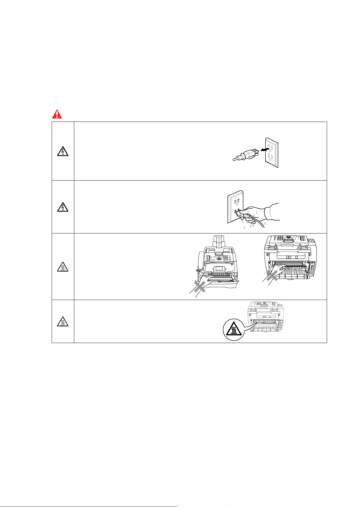
SAFETY PRECAUTIONS
To use the machine safely
Please keep these instructions for later reference and read them before attempting any maintenance.
NOTE: (For FAX-2820/2825 and MFC-7220/7225N) If there are faxes in the machine's memory,
you need to print them or save them before you turn off the power and unplug the machine.
WARNING
There are high voltage electrodes
inside the machine. Before you
clean the inside of the machine,
make sure you have unplugged
the telephone line cord first and then
the power cord from the AC
power outlet.
Do not handle the plug with wet
hands. Doing this might cause an
electrical shock.
After you use the machine, some
internal parts are extremely HOT!
To prevent injures, be careful not to
put your fingers in the area shown in
the illustration.
The fixing unit is marked with a
caution label. Please do not remove
or damage the label.
Use caution when installing or modifying telephone lines. Never touch telephone wires or
terminals that are not insulated unless the telephone line has been disconnected at the walljack.
Never install telephone wiring during a lightning storm. Never install a telephone wall jack in a
wet location.
This product must be installed near an AC power outlet that is easily accessible. In case of an
emergency, you must disconnect the power cord from the AC power outlet to shut off the power
completely.
Do not use a vacuum cleaner to clean up scattered toner. Doing this might cause the toner dust to
ignite inside the vacuum cleaner, potentially starting a fire. Please carefully clean the toner dust with
a dry, lint-free cloth and dispose of it according to local regulations.
Confidential
viii
Page 11

WARNING
DO not use any type of spray to clean inside or outside of the machine.
Doing this may cause a fire or electrical shock.
WARNING
IMPORTANT SAFETY INSTRUCTIONS
When using your telephone equipment, basic safety precautions should always be followed to
reduce the risk of fire, electric shock and injury to people, including the following:
1. Do not use this product near water, for example, near a bath tub, wash bowl, kitchen sink or
washing machine, in a wet basement or near a swimming pool.
2. Avoid using this product during an electrical storm. There may be a remote risk of electric
shock from lightning.
3. Do not use this product to report a gas leak in the vicinity of the leak.
4. Use only the power cord supplied with this machine.
SAVE THESE INSTRUCTIONS
Confidential
ix
Page 12
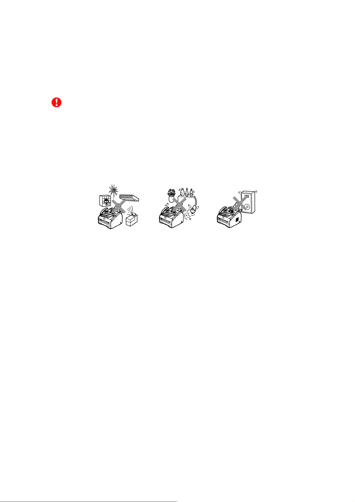
CHOOSING A LOCATION
Place your machine on a flat, stable surface that is free of vibration and shocks, such as a desk.
Put the machine near a telephone wall jack and a standard, grounded AC power outlet. Choose
a location where the temperature remains between 50°F and 90.5°F (10°C and 32.5°C).
CAUTION
• Avoid placing your machine in a high-traffic area.
• Do not place the machine near heaters, air conditioners, water, chemicals, or refrigerators.
• Do not expose the machine to direct sunlight, excessive heat, moisture, or dust.
• Do not connect your machine to an AC power outlet controlled by wall switches or automatic
timers.
• Disruption of power can wipe out information in the machine’s memory.
• Do not connect your machine to an AC power outlet on the same circuit as large appliances or
other equipment that might disrupt the power supply.
• Avoid interference sources, such as speakers or the base units of cordless phones.
Confidential
x
Page 13

CHAPTER
PARTS NAMES & FUNCTIONS
1
Confidential
Page 14

CHAPTER 1 PARTS NAMES & FUNCTIONS
This chapter contains external views and names of components and describes their functions.
Information about the keys on the control panel is included to help you check operation or make
adjustments.
CONTENTS
1.1 EQUIPMENT OUTLINE ................................................................................................... 1-1
1.2 CONTROL PANEL...........................................................................................................1-2
1.3 COMPONENTS................................................................................................................1-5
Confidential
Page 15
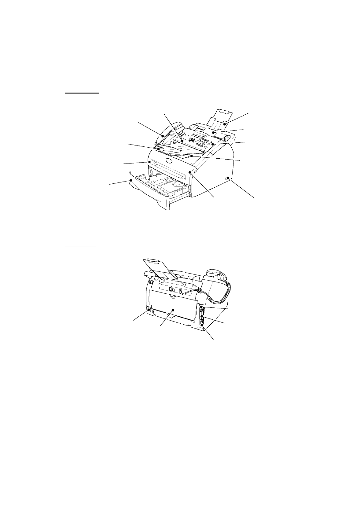
1.1 EQUIPMENT OUTLINE
Front view
Control Panel Cover
Telephone Handset
ADF Document Support
Automatic Document Feeder (ADF)
ADF Document Output Support
Manual Feed Slot
Paper Tray
Rear view
Control Panel
Face-down Output Tray
Support Flap with Extension
Front Cover
USB Interface Connector
Power Switch
AC Power Connector
Back Cover
1-1 Confidential
Parallel Interface Connector
10/100 Baser TX Port
Page 16
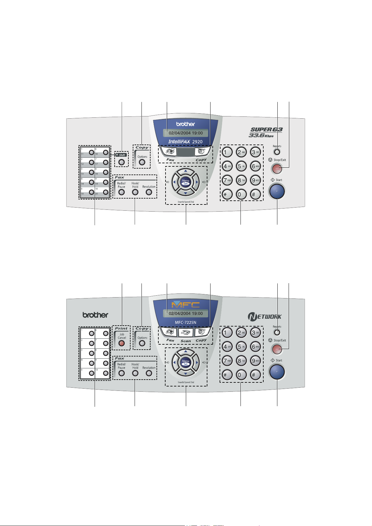
1.2 CONTROL PANEL
FAX-2820, FAX-2825, FAX-2910 and FAX-2920 have the same keys.
11
10
9 8
7
6
1
MFC-7220 and MFC-7225N have the same keys.
10 12
3 2
4
5
8 9
7
6
1
1-2 Confidential
2
3
5 4
Page 17
1. One-Touch Keys 4. Dial Pad
These 10 keys give you instant access to 10
(MFC-7220 and MFC-7225N) or 20
(FAX-2820, FAX-2825, FAX-2910 and FAX-2920)
previously stored dial numbers.
2. Fax and Telephone Keys 5. Start
Redial/Pause
Redials the last number you called. It also inserts a
pause in quick dial numbers.
Hook/Hold
Lets you dial telephone and fax numbers without lifting
the handset.
—OR—
Lets you place telephone calls on hold.
Resolution
Sets the resolution when you send a fax.
3. Navigation Keys 7. Reports
Menu/Set
The same key is used for Menu and Set operations. Lets
you access the Menu to program and store your settings
in the machine.
Volume keys
When using the handset, listening to the speaker in Fax
mode or on standby, you can press these keys to adjust
the volume.
Search/Speed Dial
Lets you look up numbers that are stored in the dialing
memory. It also lets you dial stored numbers by
pressing # and a three-digit number.
Press to scroll forward or backward to a menu selection.
Use these keys to dial telephone or fax numbers and as a
keyboard for entering information into the machine.
The # key lets you temporarily switch the dialing mode
during a telephone call from Pulse to Tone
only).
(For Canada
Lets you start sending faxes or making copies.
6. Stop/Exit
Stops an operation or exits from the menu.
Print the Transmission Verification Report, Help List,
Quick-Dial List, Fax Journal, User Settings and Network
Configuration*. (*MFC-7225N only).
8. Mode Keys
Fax
Lets you access Fax mode.
Scan
(MFC-7220 and MFC-7225N only)
Lets you access Scan mode.
Copy
Lets you access Copy mode.
or
Press to scroll through the menus and options.
1-3 Confidential
Page 18

9. Liquid Crystal Display (LCD) 11. Shift
(FAX-2820, FAX-2825, FAX-2910 and FAX-2920 only)
Displays messages on the screen to help you set up and
use your machine.
10. Copy Key (Temporary settings)
Options
You can quickly and easily select temporary settings for
copying.
To access One-Touch numbers 11 to 20, hold down
Shift as you press the One-Touch key.
12. Printer Key
(MFC-7220 and MFC-7225N only)
Job Cancel
You can cancel a print job and clear the printer memory.
1-4 Confidential
Page 19
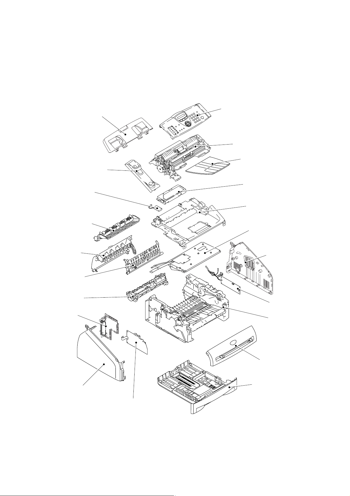
1.3 COMPONENTS
N
The equipment consists of the following major components:
Document Base ASSY
Handset Holder
Buttery ASSY
Inner Chute
Back Cover
Rear Chute Cover
Panel Unit
Document Chute ASSY
Paper Eject Tray
CU PCB & Shield Case
Inner Chute Cover ASSY
Laser Unit
Side Cover R
Fixing Unit
Main PCB
Side Cover L
High-voltage PS PCB
1-5 Confidential
PS PCB Unit
Frame Unit
Front Cover
Paper Tray
Page 20

CHAPTER
SPECIFICATIONS
2
Confidential
Page 21

CHAPTER 2 SPECIFICATIONS
This chapter lists the specifications of each model, which enables you to make a comparison of
different models.
CONTENTS
2.1 GENERAL........................................................................................................................ 2-1
2.1.1 General Specifications......................................................................................... 2-1
2.1.2 Paper Specifications ............................................................................................ 2-2
2.1.3 Printable Area................................................................................................................ 2-4
2.1.4 Toner Cartridge Weight Information........................................................................... 2-8
2.2 SPECIFICATIONS LIST .................................................................................................. 2-9
Confidential
Page 22

2.1 GENERAL
2.1.1 General Specifications
Memory Capacity 8 MB (FAX-2820/ FAX-2825)
Automatic Document Feeder (ADF) Up to 20 sheets
16 MB (MFC-7220/ FAX-2910/ FAX-2920)
32 MB (MFC-7225N)
Paper Tray
Printer Type Laser
Print Method Electrophotography by semiconductor laser beam
Liquid Crystal Display (LCD) 16 characters x 1 lines
Power Source 100 to 120V AC 50/60Hz
Power Consumption Sleep: 10W
Dimensions (W x D x H) 374 (W) x 374 (D) x 262(H)
Weight 16.21 b (7.35kg)
Noise Operating: 53 dB A or less
Temperature Operating: 50°F to 90.5°F (10 to 32.5°C)
Humidity Operating: 20 to 80% (without condensation)
250 Sheets (20 lb (80 g/m²))
scanning
220 to 240V AC 50/60Hz
Standby: 80W
Peak: 1040W
Standby: 30 dB A or less
Storage: 32°F to 104°F (0 to 40°C)
Storage: 10 to 90% (without condensation)
2-1 Confidential
Page 23

2.1.2 Paper Specifications
(1) Paper type
Paper type Tray1
Manual feed
slot
Select the paper type from the
printer driver
Plain paper
60 g/m2 to 105 g/m
(16 to 28 lbs.)
2
O O Plain paper
Recycled paper O O Recycled paper
Bond paper O O Bond paper
Thick paper
105 g/m2 to 161 g/m
(28 to 43 lbs.)
2
X O Thick paper or Thicker paper
O
Transparency
Up to 10 sheets
O
Transparency
A4 or Letter
Label X
Envelop X O
O
Thicker paper
Envelope or Env.Thick
or Env.Thin
Card Stock X O Thick paper or Thicker paper
(2) Paper size
Paper size
Paper Tray
A4, Letter, Legal*, B5 (ISO),
Executive, A5, A6, B6 (ISO),
B5 (JIS), Folio*
Width:
69.9 to 215.9 mm (2.75 to 8.5 in.)
Length:
Manual feed slot
116 to 406.4 mm (4.57 to 16.0 in.)
* Legal and Folio are not available in some regions.
(3) Other paper specifications
<Paper tray>
Cut sheet
Basis weight 60 to 105 g/m2 (16 to 28 lb.)
Caliper 0.08 to 0.12 mm (0.003 to 0.005 in.)
Moisture content 4% to 6% by weight
<Manual feed slot>
Cut sheet
Basis weight 60 to 161 g/m2 (16 to 43 lb.)
Caliper 0.08 to 0.19 mm (0.003 to 0.007 in.)
Moisture content 4% to 6% by weight
2-2 Confidential
Page 24

(4) Recommended paper
Europe USA
Plain paper Xerox Premier 80 g/m
Xerox Business 80 g/m
Modo Paper DATACOPY 80 g/m
IGEPA X-press 80 g/m2
2
2
Xerox 4200DP 20lb
Xerox 4024 28lb
2
Hammermill Laser Paper 24lb
Recycled paper
Transparency
Label
Xerox Recycled Supreme Xerox Recycled Supreme
3M CG3300 3M CG 3300
Avery laser label L7163 Avery laser label #5160
* This printer can use recycled paper that meets the DIN 19309 specification
CAUTION:
When you are choosing print media, be sure to follow the information given below to prevent
any paper jams, print quality problems or printer damage;
• It is recommended to use long-grained paper for the best print quality. If short-grained
paper is being used, it might be the cause of paper jams.
• Use neutral paper. Do not use acid paper to avoid any damage to the drum unit.
• Avoid using coated paper such as vinyl coated paper.
• Avoid using preprinted or highly textured paper.
• It is recommended to use labels or transparencies which are designed for use in laser
printers.
• Avoid feeding labels with the carrier sheet exposed, or the printer will be damaged.
• Before loading paper with holes such as organizer sheets, be sure to fan the stack well.
• Do not use organizer sheets that are stuck together. The glue that is used might caused
damaged to the printer.
• When printing on the back of pre-printed paper, if the paper is curled, be sure to
straighten the paper as much as possible.
Different types of paper should not be loaded at the same time in the paper tray to avoid any
paper jams or misfeeds.
(5) Paper tray capacity
Paper Tray
Manual feed slot
Paper Capacity 250 sheets (80 g/m2 or 21lb) Single sheet
(6) Print delivery
Face down output tray
2
capacity: Maximum 100 sheets (80 g/m
)
face down only
NOTE:
Face-down: Delivery with the printed face of the paper downwards.
2-3 Confidential
Page 25
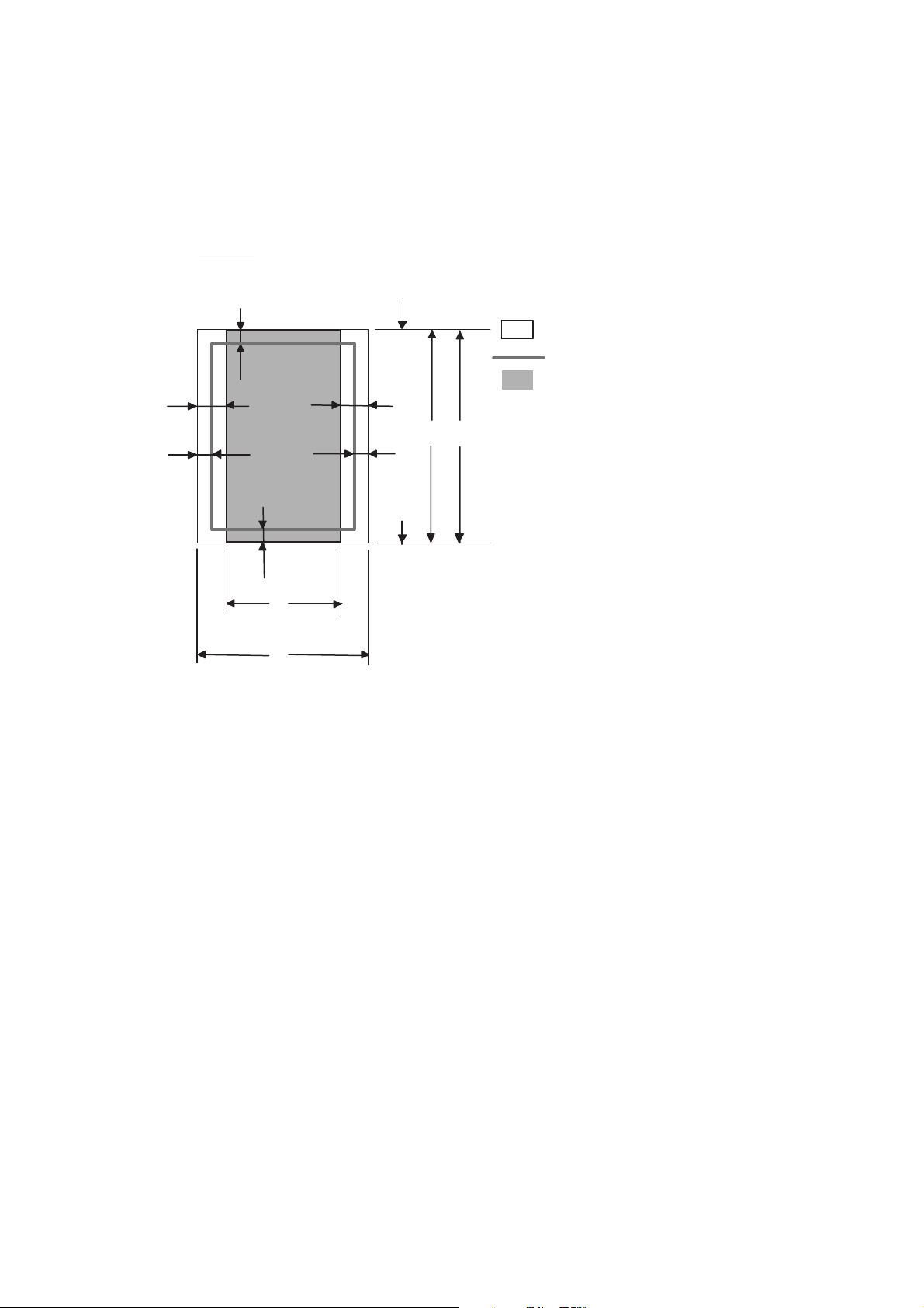
2.1.3 Printable Area
When using PCL emulation, the edges of the paper that cannot be printed on are shown below.
Portrait
G
E
G
G
C
A
F
Physical page
Printable area
Logical page
E
B
D
G
F
B Physical page length
D
F
Maximum logical page length
Distance from edge of physical page to
edge of logical page
NOTE:
• “Logical page” shows the printable area for a PCL driver.
• “Printable area” shows mechanical printable area of the machine.
• Therefore, the machine can only print within the shaded area when you use a PCL driver.
2-4 Confidential
Page 26

The table below shows the printable areas when printing on Portrait for each paper size.
Size A B C D E F G
Letter
Legal
Folio
Executive
A4
A5
A6
B5 (JIS)
B5 (ISO)
B6 (ISO)
COM10
MONARCH
C5
DL
DLL
215.9 mm
8.5”
(2,550 dots)
215.9 mm
8.5”
(2,550 dots)
215.9 mm
8.5”
(2,550 dots)
184.15 mm
7.25”
(2,175 dots)
210.0 mm
8.27”
(2,480 dots)
148.5 mm
5.85”
(1,754 dots)
105.0 mm
4.13”
(1,240 dots)
182.0 mm
7.1”
(2,130 dots)
176.0 mm
6.93”
(2,078 dots)
125.0 mm
4.92”
(1,476 dots)
104.78 mm
4.125”
(1,237 dots)
98.43 mm
3.875”
(1,162 dots)
162.0 mm
6.38”
(1,913 dots)
110.0 mm
4.33”
(1,299 dots)
220.0 mm
8.66”
(2,598 dots)
279.4 mm
11.0”
(3,300 dots)
355.6 mm
14.0”
(4,200 dots)
330.2mm
13.0”
(3,900 dots)
266.7 mm
10.5”
(3,150 dots)
297.0 mm
11.69”
(3,507 dots)
210.0 mm
8.27”
(2,480 dots)
148.5 mm
5.85”
(1,754 dots)
257.0 mm
10.11”
(3,033 dots)
250.0 mm
9.84”
(2,952 dots)
176.0 mm
6.93”
(2,078 dots)
241.3 mm
9.5”
(2,850 dots)
190.5 mm
7.5”
(2,250 dots)
229.0 mm
9.01”
(2,704 dots)
220.0 mm
8.66”
(2,598 dots)
110.0 mm
4.33”
(1,299 dots)
203.2 mm
8.0”
(2,400 dots)
203.2 mm
8.0”
(2,400 dots)
203.2 mm
8.0”
(2,400 dots)
175.7 mm
6.92”
(2,025 dots)
198.0 mm
7.79”
(2,338 dots)
136.5 mm
5.37”
(1,612 dots)
93.0 mm
3.66”
(1,098 dots)
170.0 mm
6.69”
(2,007 dots)
164.0 mm
6.46”
(1,936 dots)
164.0 mm
4.44”
(1,334 dots)
92.11 mm
3.63”
(1,087 dots)
85.7 mm
3.37”
(1,012 dots)
150.0 mm
5.9”
(1,771 dots)
98.0 mm
3.86”
(1,157 dots)
207.4 mm
8.17”
(2,450 dots)
279.4 mm
11.0”
(3,300 dots)
355.6 mm
14.0”
(4,200 dots)
330.2mm
13.0”
(3,900 dots)
266.7 mm
10.5”
(3,150 dots)
297.0 mm
11.69”
(3,507 dots)
210.0 mm
8.27”
(2,480 dots)
148.5 mm
5.85”
(1,754 dots)
257.0 mm
10.11”
(3,033 dots)
250.0 mm
9.84”
(2,952 dots)
176.0 mm
6.93”
(2,078 dots)
241.3 mm
9.5”
(2,850 dots)
190.5 mm
7.5”
(2,250 dots)
229.0 mm
9.01”
(2,704 dots)
220.0 mm
8.66”
(2,598 dots)
110.0 mm
4.33”
(1,299 dots)
6.35 mm
0.25”
(75 dots)
6.35 mm
0.25”
(75 dots)
6.35 mm
0.25”
(75 dots)
6.35 mm
0.25”
(75 dots)
6.01 mm
0.24”
(71 dots)
6.01 mm
0.24”
(71 dots)
6.01 mm
0.24”
(71 dots)
6.01 mm
0.24”
(71 dots)
6.01 mm
0.24”
(71 dots)
6.01 mm
0.24”
(71 dots)
6.35 mm
0.25”
(75 dots)
6.35 mm
0.25”
(75 dots)
6.01 mm
0.24”
(71 dots)
6.01 mm
0.24”
(71 dots)
6.27 mm
0.25”
(74 dots)
0 mm
0 mm
0 mm
0 mm
0 mm
0 mm
0 mm
0 mm
0 mm
0 mm
0 mm
0 mm
0 mm
0 mm
0 mm
NOTE:
• The paper sizes indicated here should confirm to the nominal dimensions specified by JIS
except B5 (ISO), B6 (ISO).
• The dot size is based on 300 dpi resolution.
4.2 mm
0.16”
(50 dots)
4.2 mm
0.16”
(50 dots)
4.2 mm
0.16”
(50 dots)
4.2 mm
0.16”
(50 dots)
4.2 mm
0.16”
(50 dots)
4.2 mm
0.16”
(50 dots)
4.2 mm
0.16”
(50 dots)
4.2 mm
0.16”
(50 dots)
4.2 mm
0.16”
(50 dots)
4.2 mm
0.16”
(50 dots)
4.2 mm
0.16”
(50 dots)
4.2 mm
0.16”
(50 dots)
4.2 mm
0.16”
(50 dots)
4.2 mm
0.16”
(50 dots)
6.27 mm
0.25”
(74 dots)
2-5 Confidential
Page 27
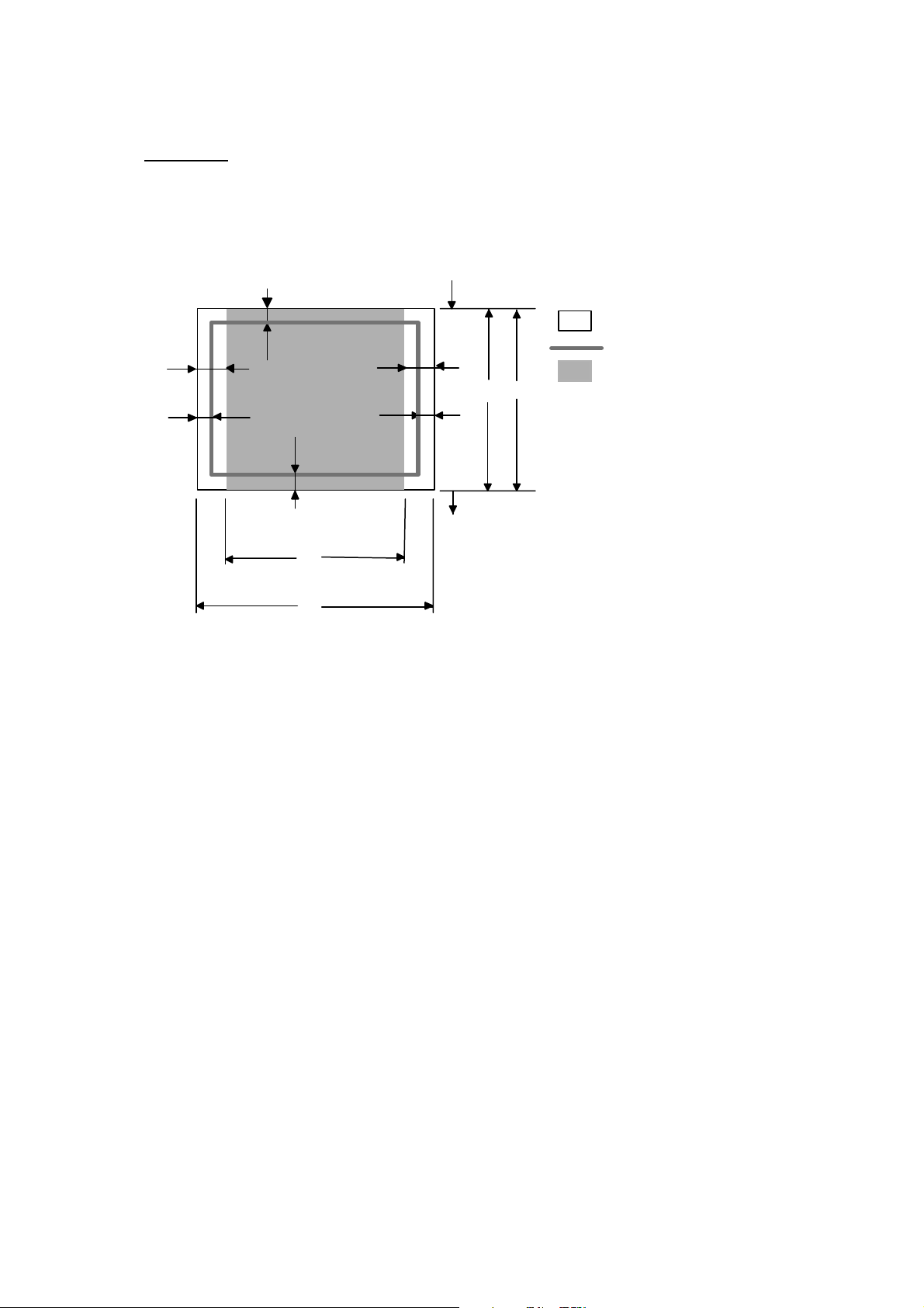
Landscape
G
E
G
G
C
A
F
Physical page
Printable area
E
D
B
G
B Physical page length
D Maximum logical page length
F Distance from edge of physical
page to edge of logical page
F
Logical page
NOTE:
• “Logical page” shows the printable area for a PCL driver.
• “Printable area” shows mechanical printable area of the machine.
• Therefore, the machine can only print within the shaded area when you use a PCL driver.
2-6 Confidential
Page 28

The table below shows the printable areas when printing on Landscape for each paper size.
Size A B C D E F G
Letter
Legal
Folio
Executive
A4
A5
A6
B5 (JIS)
B5 (ISO)
B6 (ISO)
COM10
MONARCH
C5
DL
DLL
279.4 mm
11.0”
(3,300 dots)
355.6 mm
14.0”
(4,200 dots)
330.2mm
13.0”
(3,900 dots)
266.7 mm
10.5”
(3,150 dots)
297.0 mm
11.69”
(3,507 dots)
210.0 mm
8.27”
(2,480 dots)
148.5 mm
5.85”
(1,754 dots)
257.0 mm
10.11”
(3,033 dots)
250.0 mm
9.84”
(2,952 dots)
176.0 mm
6.93”
(2,078 dots)
241.3 mm
9.5”
(2,850 dots)
190.5 mm
7.5”
(2,250 dots)
229.0 mm
9.01”
(2,704 dots)
220.0 mm
8.66”
(2,598 dots)
110.0 mm
4.33”
(1,299 dots)
215.9 mm
8.5”
(2,550 dots)
215.9 mm
8.5”
(2,550 dots)
215.9 mm
8.5”
(2,550 dots)
184.15 mm
7.25”
(2,175 dots)
210.0 mm
8.27”
(2,480 dots)
148.5 mm
5.85”
(1,754 dots)
105.0 mm
4.13”
(1,240 dots)
182.0 mm
7.1”
(2,130 dots)
176.0 mm
6.93”
(2,078 dots)
125.0 mm
4.92”
(1,476 dots)
104.78 mm
4.125”
(1,237 dots)
98.43 mm
3.875”
(1,162 dots)
162.0 mm
6.38”
(1,913 dots)
110.0 mm
4.33”
(1,299 dots)
220.0 mm
8.66”
(2,598 dots)
269.3 mm
10.6”
(3,180 dots)
345.5 mm
13.6”
(4,080 dots)
320.0 mm
12.6”
(3,780 dots)
256.6 mm
10.1”
(3,030 dots)
287.0 mm
11.2”
(3,389 dots)
200.0 mm
7.87”
(2,362 dots)
138.5 mm
5.45”
(1,636 dots)
247.0 mm
9.72”
(2,916 dots)
240.0 mm
9.44”
(2,834 dots)
166.4 mm
6.55”
(1,960 dots)
231.1 mm
9.1”
(2,730 dots)
180.4 mm
7.1”
(2,130 dots)
219.0 mm
8.62”
(2,586 dots)
210.0 mm
8.26”
(2,480 dots)
97.5 mm
3.84”
(1,151 dots)
215.9 mm
8.5”
(2,550 dots)
215.9 mm
8.5”
(2,550 dots)
215.9 mm
8.5”
(2,550 dots)
184.15 mm
7.25”
(2,175 dots)
210.0 mm
8.27”
(2,480 dots)
148.5 mm
5.85”
(1,754 dots)
105.0 mm
4.13”
(1,240 dots)
182.0 mm
7.1”
(2,130 dots)
176.0 mm
6.93”
(2,078 dots)
125.0 mm
4.92”
(1,476 dots)
104.78 mm
4.125”
(1,237 dots)
98.43 mm
3.875”
(1,162 dots)
162.0 mm
6.38”
(1,913 dots)
110.0 mm
4.33”
(1,299 dots)
220.0 mm
8.66”
(2,598 dots)
5.0 mm
0.2”
(60 dots)
5.0 mm
0.2”
(60 dots)
5.0 mm
0.2”
(60 dots)
5.0 mm
0.2”
(60 dots)
4.8 mm
0.19”
(59 dots)
4.8 mm
0.19”
(59 dots)
4.8 mm
0.19”
(59 dots)
4.8 mm
0.19”
(59 dots)
4.8 mm
0.19”
(59 dots)
4.8 mm
0.19”
(59 dots)
5.0 mm
0.2”
(60 dots)
5.0 mm
0.2”
(60 dots)
4.8 mm
0.19”
(59 dots)
4.8 mm
0.19”
(59 dots)
6.27 mm
0.25”
(74 dots)
0 mm
0 mm
0 mm
0 mm
0 mm
0 mm
0 mm
0 mm
0 mm
0 mm
0 mm
0 mm
0 mm
0 mm
0 mm
NOTE:
• The paper sizes indicated here should confirm to the nominal dimensions specified by JIS
except B5 (ISO), B6 (ISO).
• The dot size is based on 300 dpi resolution.
4.2 mm
0.16”
(50 dots)
4.2 mm
0.16”
(50 dots)
4.2 mm
0.16”
(50 dots)
4.2 mm
0.16”
(50 dots)
4.2 mm
0.16”
(50 dots)
4.2 mm
0.16”
(50 dots)
4.2 mm
0.16”
(50 dots)
4.2 mm
0.16”
(50 dots)
4.2 mm
0.16”
(50 dots)
4.2 mm
0.16”
(50 dots)
4.2 mm
0.16”
(50 dots)
4.2 mm
0.16”
(50 dots)
4.2 mm
0.16”
(50 dots)
4.2 mm
0.16”
(50 dots)
6.27 mm
0.25”
(74 dots)
2-7 Confidential
Page 29
2.1.4 Toner Cartridge Weight Information
Toner Cartridge Weight (approximate weight)
TN-2000 EU/ EEU
Made in China
TN-2000 EU/EEU
Made in Malaysia
Brand new Toner Cartridge Weight 570g (± 10g)
(Recycle: 584g(± 10g))
460g (± 10g)
(Recycle: 474g(± 10g))
Toner Weight at Brand New Toner Cartridge 100g 100g
Toner Cartridge Weight at Toner Near Empty 516g 406g
Remain Toner Weight at Toner Near Empty 46g 46g
Toner Cartridge Weight at Toner Life End 514g 404g
Remain Toner Weight at Toner Life End 44g 44g
You can print 500 pages (± 100 pages) with 10g toner. (5% coverage)
For TN-2000 EU/ EEU:
• To distinguish the place of production is to check the serial number of toner cartridge. For
example, “F5J
xxxxxxxA” J stands for “Made in China”. “K5PxxxxxxxD” P stands for “Made in
Malaysia”.
• Due to a change of the developing roller, the weight of TN-2000 (Made in China) is reduced
about 50g with the serial number of toner cartridge, “B6JA018935A” or later.
TN-350 US/ TN-2025 AP/ TN-2075 RUS
Brand new Toner Cartridge Weight 570g (± 10g)
Toner Weight at Brand New Toner Cartridge 100g
Toner Cartridge Weight at Toner Near Empty 516g
Remain Toner Weight at Toner Near Empty 46g
Toner Cartridge Weight at Toner Life End 516g
Remain Toner Weight at Toner Life End 44g
You can print 500 pages (± 100 pages) with 10g toner. (5% coverage)
NOTE:
• Without yellow protector
• Toner cartridge weight may vary within 2 to 3g depending on the cartridge weight.
• The weight of the starter toner cartridge is as follows,
For TN2000 model, the starter toner cartridge weight is 610g, and the toner weight is 80g.
For TN350, TN2050 and TN2025 models, the starter toner cartridge weight is 550g, and the toner
weight is 80g.
• The toner weight at brand new toner cartridge is changed from 100g to 106g. (Serial number of
toner cartridge is from E5JA000001B.)
2-8 Confidential
Page 30
2.2 SPECIFICATIONS LIST
p
p
y
p
y
y
FAX-2820/2825/2920
(1/7)
Model Name
US/
Canada
Europe
FAX-2820/2825
Asia/
Pacific
US/
Canada
GENERAL
Print Engine
CPU S
eed
Back up Clock
Operating Environment
erature
Tem
Humidit
On/Off Switch
AC Cord inlet No No
Demo Print
Demo Model
Starter Toner Starter Starter
Simultaneous Operation
Input / Output Width
Input / Output Length
ADF
Paper Capacity
Optional Paper Tray
Multi-Pur
Output Paper
Capacity(sheets)
Lower Tra
LCD Size
LCD Back-Lit
On-Screen Programming
Memory Capacity (Standard
: MByte)
Memory BackUp
Optional Memory
Memory Security
Transmission Lock
Setting Lock
Dimensions w/ Carton
(WxDxH)
Dimensions w/o Carton
(WxDxH)
ose Tra
- Automatic
20% - 80% (without condensation)
(US only)
147.3-215.9 mm / 69.9-215.9 mm
100.0-356.0 mm/ 116.0-406.4 mm
up to 20 sheets (Conditional* 30
environment: temp. 20-30C humiditiy
Laser ( ALL)
SparcLite 96MHz
2hours
10 - 32.5 degrees Centigrade
Yes Yes
Yes
5.8"-8.5" / 2.75"-8.5"
3.9"-14" / 4.56"-16"
(*: XX4024 or 4200 20lbs,
50-70%)
250 sheets
up to 100 sheets
16 characters x 1 lines
8 Mbyte (RAM)
452 x 496 x 430mm
17.8 x 19.5 x 16.9 inch
374 x 374 x 262 mm 374 x 374 x 262 mm
14.7 x 14.7 x 10.3 inch 14.7 x 14.7 x 10.3 inch
N/A
N/A
Full Full
Yes
sheets)
N/A
N/A
N/A
N/A
Yes
N/A
N/A
N/A
Yes N/A
Yes Yes
10 - 32.5 degrees Centigrade
20% - 80% (without condensation)
147.3-215.9 mm / 69.9-215.9 mm
100.0-356.0 mm/ 116.0-406.4 mm
up to 20 sheets (Conditional* 30
(*: XX4024 or 4200 20lbs,
environment: temp. 20-30C humiditiy
452 x 496 x 430mm
17.8 x 19.5 x 16.9 inch
Europe
FAX-2920
Laser ( ALL)
SparcLite 96MHz
Yes (up to 4 days)
YesYes
N/A
N/A
Yes
5.8"-8.5" / 2.75"-8.5"
3.9"-14" / 4.56"-16"
sheets)
50-70%)
250 sheets
N/A
N/A
up to 100 sheets
N/A
16 characters x 1 lines
Yes (1-color)
Yes
16 Mbyte (RAM)
Yes (up to 4 days)
N/A
Yes
Pacific
Asia/
N/A
N/A
N/A
N/A
2-9 Confidential
Page 31

(2/7)
p
(
)
(
)
g
(
(
Model Name
US/
Canada
Europe
FAX-2820/2825 FAX-2920
Asia/
Pacific
US/
Canada
Europe
Asia/
Pacific
GENERAL
Approx.
Approx.
Weight w/ Carton
Weight w/o Carton (w/o
Process unit)
Color N/A
Power Source
Power Consumption
(Copying)
Power Consum
Power Save
Sleep Mode (00-99min : w/
Energy Star Compliant
Total Print pages Counter
(Internal / LCD / Print)
Copy pages Counter
(Internal / LCD / Print)
PC print pages Counter
(Internal / LCD / Print)
Fax RX pages counter
Internal / LCD / Print
tion N/A
CPU Sleep
10.8 kg
(Approx.
23.8 lbs.)
Approx.
7.35 kg
(Approx.
16.2 lbs.)
Front/TOP Cover : 1737Gray / Side
120V AC
50/60
(Canada)Hz
Yes Yes
Yes / Yes/
Yes
11.4 kg
(Average
weight. The
specific weight
varies country
to country)
Approx. 7.25 kg
cover : 1736Gray
220-240V AC 50/60Hz
475W
10W/80W/1032W 10W/80W/1032W
N/A N/A
Yes
Yes / Yes/ Yes
Yes / Yes/ Yes
No / No/ No
Yes / Yes/ Yes
Approx.
11.3 kg
N/A
Yes / Yes/
Yes
Approx.
10.8 kg
(Approx.
23.8 lbs.)
Approx.
7.35 kg
(Approx.
16.2 lbs.)
Front/TOP Cover :
1737Gray / Side cover :
120V AC
50/60
(Canada)Hz
Approx.
11.4 kg
(Average
weight. The
specific weight
varies country
to country)
Approx. 7.25 kg
1736Gray
220-240V AC 50/60Hz
475W
Yes
Yes / Yes/ Yes
Yes / Yes/ Yes
Yes / Yes/ Yes
Yes / Yes/ Yes
Yes / Yes/ Yes
N/A
N/A
N/A
TELEPHONE
<FAX-2820>
WEU: No
Handset Yes
Off Hook Alarm
Power Failure Phone
Power Failure Dilalling
Chain Dialing
Automatic Redial
PBX Feature N/A N/A
Speaker Phone
Handset Volume
Speaker Volume
Buzzer Volume
Ring Volume
Hold/Mute Key
Music on Hold
Monitorin
One-Touch Dial
the Line on Hold
(2 steps
&
volume
amplify)
EEU&Russia:
Yes
<FAX-2825>
Yes
N/A
N/A
N/A
Yes
Yes
N/A N/A
Yes (3 steps + OFF)
Yes (3 steps + OFF)
Yes (3 steps + OFF)
Yes Yes
N/A
N/A
10 x 2) locations
20
Yes Yes
Yes
(2 steps
&
volume
amplify)
WEU/EEU&
Russia
(No/Yes)
N/A
N/A
N/A
Yes
YesYes
N/AN/A
Yes
N/A N/A
Yes (3 steps + OFF)
Yes (3 steps + OFF)
Yes (3 steps + OFF)
N/A
N/A
20
10 x 2) locations
Yes
Yes
2-10 Confidential
Page 32

US/
A
p
p
)
)
g
Canada
Model Name
TELEPHONE
Speed Dial
Figures of One-Touch &
eed Dial
S
Resisterable Number Of
Characters
Group Dial
Tele
hone Index (Search
Pre-registered for FAX
BACK SYSTEM ( USA )
Caller ID Yes N/A
Call Waiting Caller ID
Call waiting Ready ( Only for
USA )
Distinctive Ringing Yes
Yes (with ▼
key)
Europe
FAX-2820/2825 FAX-2920
200 locations 200 locations
20 digits 20 digits
15 characters
Yes (up to 8 groups)
Yes (with ▼key)
N/A
N/A
Yes (U.K.,
Den. only)
Pacific
Yes(ARL/
NZ/SIN/HK
N/A
Yes(ARL/
NZ/SIN/HK
sia/
only)
only)
US/
Canada
Yes (up to 8 groups)
Yes N/A
Yes (with ▼
key)
Yes
(3/7)
Europe
15 characters
Yes (with ▼ key)
N/A
N/A
N/A
Yes (U.K.,
Den. only)
Asia/
Pacific
Yes(ARL/
NZ/SIN/HK
only)
Yes(ARL/
NZ/SIN/HK
only)
FAX
Modem Speed
Transmission Speed
ITU-T Group
Coding Method
Color FAX (Document Send
/ Receive)
Color FAX (Memory Send /
Receive
Fax/Tel Switch
Super Fine
Gray Scale
Contrast
Smoothing
Dual Access
Enhanced Remote Activate
Station ID
Remote Maintenance
RX Mode Indication
Resolution Indication
Delayed Timer
Polled Sendin
Multi Transmission
Multi Resolution
Transmission
Next-Fax Reservation
Batch Transmission
Call Reservation Over Auto
TX
Call Reservation Over
Manual TX
Quick-Scan(Memory
transmission)
Memory Transmission
14.400bps (Fax)
Approx. 6sec. (Brother #1 & ITU-T #1,
MMR)
G3
MH / MR / MMR
N/A
N/A
Yes
Yes (TX & RX)
64
Yes (Auto/Light/Dark)
N/A
Yes
Yes Yes
Yes (20digits / 20characters)
Yes
LCD
LCD
Yes (up to 50)
Yes (Eur : Secure Polling)
N/A
N/A
N/A
Yes
N/A
N/A
Approx. 3.5 sec./page (Letter/A4,
Standard Resolution)
up to 400 pages (ITU-T Test Chart,
Standard Resolution, MMR)
up to 500 pages ((Brother #1Chart,
Standard Resolution, MMR)
33.600bps (Fax)
Approx. 2sec. (Brother #1 & ITU-T #1,
JBIG)
Super G3
MH / MR / MMR / JBIG
N/A
N/A
Yes
Yes (TX & RX)
64
Yes (Auto/Light/Dark)
N/A
Yes
Yes (20digits / 20characters)
Yes
LCD
LCD
Yes (up to 50)
Yes (Eur : Secure Polling)
N/A
N/A
N/A
Yes
N/A
N/A
Approx. 3.5 sec./page (Letter/A4,
Standard Resolution)
up to 500 pages (ITU-T Test Chart,
Standard Resolution, JBIG)
up to 600 pages ((Brother #1Chart,
Standard Resolution, JBIG)
2-11 Confidential
Page 33

(
)
(
)
)
(
)
(4/7)
Model Name
US/
Canada
Europe
FAX-2820/2825 FAX-2920
Asia/
Pacific
US/
Canada
FAX
ECM(Error Correction Mode)
Error Re-Transmission
Broadcasting
Manual Broadcasting
Easy Receive/Fax Detect
Polling Receiving
Auto Reduction
Duplex Fax Receive
Out-of-Paper Reception
PC Fax
up to 400 pages (ITU-T Test Chart,
Standard Resolution, MMR)
up to 500 pages ((Brother #1Chart,
Standard Resolution, MMR)
Yes No Yes
Yes Yes
Yes Yes
Yes (270 locations)
Yes (50 locations )
Yes
Yes
Yes
N/A
up to 500 pages (ITU-T Test Chart,
Standard Resolution, JBIG)
up to 600 pages ((Brother #1Chart,
Standard Resolution, JBIG)
Download from Web Site (Send only)
LIST/REPORT
Activity Report/Journal
Report
Transmission Verification
Report
Coverpage
Help List
Call Back Message
Caller ID List Yes N/A
Quick Dial List
Quick Dial List
Tel Index List
Memory Status List
System Setup(User Setting)
List
Order Form N/A N/A
New *1
Yes (up to 200)
Yes
Yes (Super)
Yes
N/A
N/A
Yes
N/A
N/A
Yes
Yes
Yes(ARL/
NZ/SIN/HK
only)
Yes N/A N/A
Europe
Yes (270 locations)
Yes (50 locations )
Yes
Yes
Yes
N/A
Yes (up to 200)
Yes
Yes (Super)
Yes
N/A
N/A
Yes
N/A
N/A
Yes
Yes
Asia/
Pacific
INTERFACE
External TAD Interface
Host Interface (Serial)
Host Interface (IEEE1284)
Host Interface (Full-Speed
USB2.0)
Ether Net (10/100base-TX)
Cable included
Acceptable Media Card Slot
PRINTER
Color/Mono Mono N/A Mono
Engine Type Laser (ALL) N/A Laser (ALL)
Resolution
Speed(ppm)
Duplex Printing Speed (ppm)
Yes
Driver
Download
1200x600d
pi
up to
15ppm
Letter size
Yes
N/A
N/A
No (Hide
the USB
port)
N/A
N/A
N/A
N/A
N/A
N/A
N/A
Yes
Driver
Download
1200x600d
pi
up to
14ppm (A4
size
up to
15ppm
Letter size
Yes
N/A
N/A
Yes
N/A
N/A
N/A
Driver
Download
Mono
Laser (ALL)
1200x600dpi
up to 14ppm (A4 size)
N/A
2-12 Confidential
Page 34

(5/7)
(Pap
)
(
)
(
)
y
Model Name
PRINTER
First Print Out Time
Standard Print Language
Emulation
Secure Print
Resident Fonts
Fonts Disk Based
Paper Handling Size
Manual Feed Slot
Paper Type
Sheet Weight
er Cassette
Manual Feed Slot
ADF
Utility Software
Variable Dot Print
Shingling Print
Color Enhancement
COPY
Color/Mono
Speed
First Copy Out Time ( from
READY mode *2 )
Warm up Time ( from
SLEEP mode )
Multi Copy(Stack)
Multi Copy(Sort)
Reduction/Enlargement(%)
Resolution(dpi)
Manual Duplex Copy
N in 1
Poster
Image Enhancement
Paper Type(Media) Setting
SCANNER
Color/Mono
Resolution (Hardware)
Resolution (Interporated)
Gray Scale
Scanning Speed (color)
Scanning Speed (256 gray
level)
Color Depth (Int. / Ext.)
Scan Key
Scan Image Key
Scan / OCR Key
Scan to E-mail Ke
US/
Canada
Driver
Download
Less than
10secs
Windows
GDI
LTR, LGL,
A4, B5, A5,
B6, A6,
EXE
Custom Size (2.75x4.56 - 8.5x16)
Envelope (DL/C5/CM10/Monarch)
Plain Paper, Recycled Paper,
up to
15cpm
(Letter size)
Max. 18 sec. at 73.4 F (23C)
50% - 200% in 1% increments
Europe
FAX-2820/2825 FAX-2920
N/A
N/A
N/A
N/A
N/A
N/A
N/A N/A
LTR, A4,
B5, A5,
B6, A6,
EXE
Transparency, Envelopes,
Bond paper, Labels
60 - 105 g/m2 (16 - 28 lb)
60 -161 g/m2 (16 - 43 lb)
64 - 90 g/m2 (17 - 24 lb)
N/A
N/A
N/A
N/A
Mono
up to 14cpm (A4 size)
Less than 12 sec
Yes (up to 99)
Yes
200 x 300 dpi
N/A
Yes
N/A
N/A
Yes
N/A
N/A
N/A
N/A
N/A N/A
N/A
N/A
N/A
N/A
N/A
N/A
Asia/
Pacific
Driver
Download
Less than
10secs
Windows
GDI
LTR, LGL,
A4, B5, A5,
B6, A6,
EXE
US/
Canada
Europe
Asia/
Pacific
Driver
Download
Less than 10secs
Windows GDI
N/A
N/A
N/A
LTR, LGL,
A4, B5, A5,
B6, A6,
EXE
Custom Size (2.75x4.56 - 8.5x16)
Envelope (DL/C5/CM10/Monarch)
Plain Paper, Recycled Paper,
up to
15cpm
(Letter size)
Max. 18 sec. at 73.4 F (23C)
50% - 200% in 1% increments
LTR, A4,
B5, A5,
B6, A6,
EXE
Transparency, Envelopes,
Bond paper, Labels
60 - 105 g/m2 (16 - 28 lb)
60 -161 g/m2 (16 - 43 lb)
64 - 90 g/m2 (17 - 24 lb)
N/A
N/A
N/A
N/A
Mono
up to 14cpm (A4 size)
Less than 12 sec
Yes (up to 99)
Yes
200 x 300 dpi
N/A
Yes
N/A
N/A
Yes
N/A
N/A
N/A
N/A
N/A
N/A
N/A
N/A
N/A
N/A
LTR, LGL,
A4, B5, A5,
B6, A6,
EXE
2-13 Confidential
Page 35

Model Name
g
(Pap
)
)
)
(*5)
)
r
r
US/
Canada
Europe
FAX-2820/2825 FAX-2920
Asia/
Pacific
US/
Canada
MESSAGE
TAD Type
ICM Recording Time
OGM (MC;MC
Pro;Paging;F/T)
Memo/Recordin
Toll Saver
Remote Access
Fax Retrieval
Fax Forwarding
Paging Yes Yes
N/A
N/A
N/A
N/A
N/A
Yes
Yes
Yes
N/A
Europe
N/A
N/A
N/A
N/A
N/A
Yes
Yes
Yes
(6/7)
Asia/
Pacific
N/A
BUNDLED
Printer Driver
TWAIN (WIA for XP)
Viewer
Control Center
PC Fax Send : Fax Share
Software by Brother
PC Fax Receive (Parallel &
USB only)
Remote Setup
BRAdmin Professional
WebBRAdmin (*5
Network Print Software
( LPR ) (*5)
Network Print Software
( NetBIOS/SMTP)
Support OS version
erPort 9.0
BUNDLED
Printer Driver
TWAIN
Viewer (PageManager)
Control Center
PC Fax (Sending only by
Brother)
PC Fax Receive
Remote Setup
Support OS version
w/o CD-ROM w/o CD-ROM
Yes
(Download
from WEB
Site)
Yes
(Download
from WEB
Site
98/98SE/Me/2000/XP Drive
No
N/A
N/A
N/A
No
N/A N/A
No
N/A
N/A
N/A
N/A
Yes
(Download
from WEB
Site)
Yes
(Download
from WEB
Site
w/o CD-ROM
Yes
(Download
from WEB
Site)
Yes
(Download
from WEB
Site)
Mac OS 9.1 - 9.2, Mac OS X 10.2.4 or
No
N/A
N/A
N/A
No
N/A
No
greater
Yes
(Download
from WEB
Site)
Yes
(Download
from WEB
Site)
Yes (Download from WEB Site)
N/A
N/A
N/A
Yes (Download from WEB Site)
No
N/A
N/A
N/A
N/A
98/98SE/Me/2000/XP Drive
w/o CD-ROM
Yes (Download from WEB Site)
N/A
N/A
N/A
Yes (Download from WEB Site)
N/A
No
Mac OS 9.1 - 9.2, Mac OS X 10.2.4 or
greater
2-14 Confidential
Page 36

Model Name
PHOTO CAPTURE
Standard NETWORK
US/
Canada
(7/7)
Europe
Asia/
Pacific
FAX-2820/2825 FAX-2920
N/A N/A
US/
Canada
Europe
Asia/
Pacific
Share Scanner
Share PC FAX (Send)
Internet FAX (ITU T.37
simple mode)
N/A
N/A
N/A N/A
N/A
N/A
Scan to E-mail server N/A N/A
ITU SUB Addressing
Support OS version for PC client
Network connection
Support Protocols
Network Management
N/A
N/A
N/A
N/A
N/A
N/A
N/A
N/A
N/A
N/A
Optional NETWORK (*6)
Model Name
Share Printer
Share Scanner
Share PC FAX (Send)
N/A
N/A
N/A
N/A
N/A
N/A
N/A
N/A
ACCESORY
Life / Yield
Shelf life
Toner : Approx. 2,500 pages
Drum : 12,000 pages: 1 page/job
2 years (6 months after opening)
<Temperature>
Toner
Normal condition: 0 - 40
Storage condition at a temperature of 40 to 50℃: Up to 5 days
Storage condition at a temperature of -20 to 0℃: Up to 5 days
<Humidity>
Normal condition: 35 - 85%
Drum
Storage condition at a humidity of 85 to 95%: Up to 5 days
Storage condition at a humidity of 10 to 35%: Up to 5 days
℃
Toner : Approx. 2,500 pages
Drum : 12,000 pages: 1 page/job
SERVICE
MTBF
MTTR
4,000 hours 4,000 hours
30 minutes 30 minutes
2-15 Confidential
Page 37

MFC-7220/7225N
p
y
Europe
MFC-7225NMFC-7220
(1/7)
Asia/
Pacific
Model Name
US/
Canada
Europe
Asia/
Pacific
US/
Canada
GENERAL
Print Engine
CPU Speed
Back up Clock
erating Environment Temperature
O
Humidit
On/Off Switch
AC Cord inlet No No
Demo Print
Demo Model
Starter Toner Starter Starter
Simultaneous Operation
Input / Output Width
Input / Output Length
ADF
Paper Capacity
Optional Paper Tray
Multi-Purpose Tray
Output Paper Capacity(sheets)
Lower Tray - Automatic Detection
LCD Size
LCD Back-Lit
On-Screen Programming
Memory Capacity (Standard : MByte)
Memory BackUp
Optional Memory
Memory Security
Transmission Lock
Setting Lock
Dimensions w/ Carton (WxDxH)
Dimensions w/o Carton (WxDxH)
10 - 32.5 degrees Centigrade
20% - 80% (without condensation)
Yes
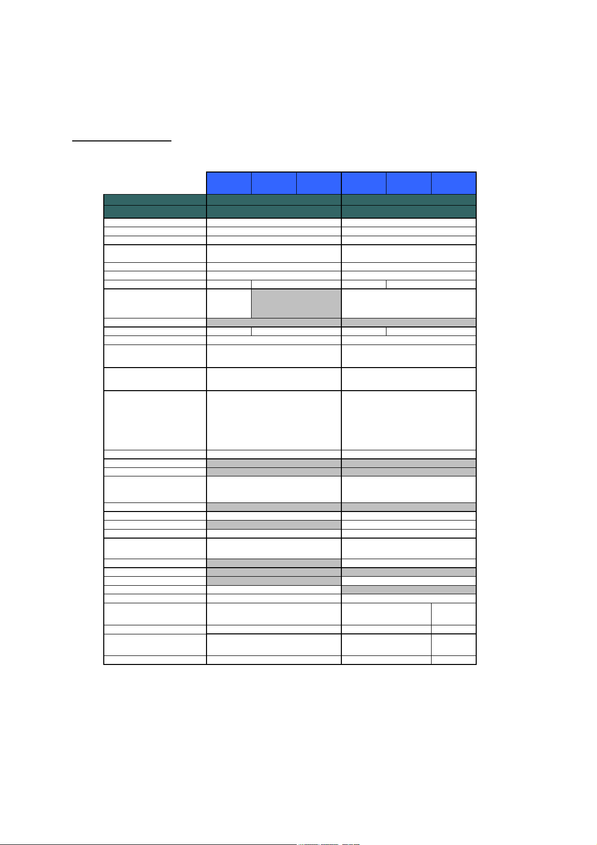
(US only)
147.3-215.9 mm / 69.9-215.9 mm
100.0-356.0 mm/ 116.0-406.4 mm
environment: temp. 20-30C humiditiy
452 x 496 x
430mm
17.8 x 19.5
x 16.9 inch
374 x 374 x
262 mm
14.7 x 14.7
x 10.3 inch
Laser ( ALL)
SparcLite 133MHz
2hours
Yes
Yes
N/A
Full (TBD)
Yes
5.8"-8.5" / 2.75"-8.5"
3.9"-14" / 4.56"-16"
up to 20 sheets
(Conditional* 30 sheets)
(*: XX4024 or 4200 20lbs,
50-70%)
250 sheets
N/A
N/A
up to 100 sheets
16 characters x 1 lines
N/A
N/A
Yes
16 Mbyte (RAM)
N/A
N/A
N/A
Yes
Yes
N/A
N/A
N/A
N/A
452 x 496 x
430mm
17.8 x 19.5
x 16.9 inch
374 x 374 x
262 mm
14.7 x 14.7
x 10.3 inch
20% - 80% (without condensation)
147.3-215.9 mm / 69.9-215.9 mm
100.0-356.0 mm/ 116.0-406.4 mm
environment: temp. 20-30C humiditiy
452 x 496 x 430mm
17.8 x 19.5 x 16.9 inch
374 x 374 x 262 mm
14.7 x 14.7 x 10.3 inch
Laser ( ALL)
SparcLite 133MHz
Yes (up to 4 days)
10 - 32.5 degrees Centigrade
Yes
Yes
N/AN/A
N/A
Full
Yes
5.8"-8.5" / 2.75"-8.5"
3.9"-14" / 4.56"-16"
up to 20 sheets
(Conditional* 30 sheets)
(*: XX4024 or 4200 20lbs,
50-70%)
250 sheets
N/A
N/A
up to 100 sheets
N/A
16 characters x 1 lines
Yes (1-color)
Yes
32 Mbyte (RAM)
Yes (up to 4 days)
N/A
Yes
N/A
Yes
N/A
N/A
N/A
N/A
2-16 Confidential
Page 38

p
(
)
)
g
g
g
g
(2/7)
Asia/
Pacific
N/A
N/A
N/A
N/A
N/A
Yes
Yes
its
Model Name
US/
Canada
Europe
MFC-7220
Asia/
Pacific
US/
Canada
GENERAL
Weight w/ Carton
Weight w/o Carton (w/o Process unit)
Color
Power Source
Power Consum
Power Consumption
(Sleep/Standby/Peak)
Power Save
Sleep Mode (00-99min : w/ OFF
mode
Energy Star Compliant ( USA Only )
Total Print pages Counter (Internal /
LCD / Print)
Copy pages Counter (Internal / LCD /
Print)
PC print pages Counter (Internal /
LCD / Print)
Fax RX pages counter (Internal / LCD
/ Print)
tion (Copying) 475W N/A 475W N/A
CPU Sleep
Approx.
10.8 kg
(Approx.
23.8 lbs.)
Approx.
7.35 kg
(Approx.
16.2 lbs.)
Front/TOP
Cover :
1581Gray /
Side cover :
1736Gray
120V AC
50/60
(Canada)Hz
10W/80W/
1040W
Yes Yes
N/A
N/A
N/A
220-240V AC 50/60Hz
N/A
N/A
Yes
Yes / Yes/ Yes
Yes / Yes/ Yes
Yes / Yes/ Yes
Yes / Yes/ Yes
Approx.
11.3 kg
(Approx.
23.8 lbs.)
Approx.
7.25 kg
Front/TOP
Cover :
1581Gray /
Side cover :
1736Gray
10W/80W/
1040W
N/A
Approx.
10.8 kg
(Approx.
23.8 lbs.)
Approx.
7.35 kg
(Approx.
16.2 lbs.)
Front/TOP Cover :
1581Gray / Side cover :
120V AC
50/60
(Canada)Hz
10W/80W/1040W
TELEPHONE
Handset Yes
Off Hook Alarm
Power Failure Phone
Power Failure Dilalling
Chain Dialing
Automatic Redial
PBX Feature N/A N/A
Speaker Phone
Handset Volume
Speaker Volume
Buzzer Volume
Ring Volume
Hold/Mute Key
Music on Hold
Monitorin
One-Touch Dial
Speed Dial
Fi
the Line on Hold with
ures of One-Touch & Speed Dial
Yes
(2 steps
& volume
amplify)
WEU/EEU&
Russia
(No/Yes)
N/A
N/A
N/A
Yes
Yes
Yes
N/A
N/A N/A
Yes (3 steps + OFF)
Yes (3 steps + OFF)
Yes (3 steps + OFF)
Yes
N/A
N/A
10 locations
200 locations
20 di
its
Yes Yes
Yes
(2 steps
& volume
amplify)
Europe
MFC-7225N
Approx.
11.4 kg
(Average
weight. The
specific weight
varies country
to country)
Approx.
7.25 kg
1736Gray
220-240V AC 50/60Hz
475W
N/A
Yes
Yes / Yes/ Yes
Yes / Yes/ Yes
Yes / Yes/ Yes
Yes / Yes/ Yes
WEU/EEU&
Russia
(No/Yes)
N/A
N/A
N/A
Yes
Yes
N/A
N/A N/A
Yes (3 steps + OFF)
Yes (3 steps + OFF)
Yes (3 steps + OFF)
Yes
N/A
N/A
10 locations
200 locations
20 di
2-17 Confidential
Page 39

Model Name
(
)
y)
y)
p
g
(
)
TELEPHONE
US/
Canada
(3/7)
Europe
MFC-7220 MFC-7225N
Asia/
Pacific
US/
Canada
Europe
Asia/
Pacific
Resisterable Number Of Characters
Group Dial
Telephone Index (Search)
Pre-registered for FAX BACK
SYSTEM
Caller ID Yes N/A
Call Waiting Caller ID
Call waiting Ready ( Only for USA )
Distinctive Ringing Yes N/A
USA
Yes (with ▼
FAX
Modem Speed
Transmission Speed
ITU-T Grou
Coding Method
Color FAX (Document Send/Receive)
Color FAX (Memory Send/Receive)
Fax/Tel Switch
Super Fine
Gray Scale
Contrast
Smoothing
Dual Access
Enhanced Remote Activate
Station ID
Remote Maintenance
RX Mode Indication
Resolution Indication
Delayed Timer
Polled Sendin
Multi Transmission
Multi Resolution Transmission
Next-Fax Reservation
Batch Transmission
Call Reservation Over Auto TX
Call Reservation Over Manual TX
Quick-Scan(Memory transmission)
Memory Transmission
ECM
Error Correction Mode
Error Re-Transmission
Approx. 6sec. (Brother #1 & ITU-T
Approx. 3.5 sec./page (Letter/A4,
up to 400 pages (ITU-T Test Chart,
up to 500 pages ((Brother #1Chart,
15 characters
Yes (up to 8 groups)
Yes (with ▼ key)
N/A
N/A
key)
14.400bps (Fax)
#1, MMR)
G3
MH / MR / MMR
N/A
N/A
Yes
Yes (TX & RX)
64
Yes (Auto/Light/Dark)
N/A
Yes
Yes
Yes (20digits / 20characters)
Yes
LCD
LCD
Yes (up to 50)
Yes (Eur : Secure Polling)
N/A
N/A
N/A
Yes
N/A
N/A
Standard Resolution)
Standard Resolution, MMR)
Standard Resolution, MMR)
Yes
Yes
Yes(ARL/
NZ/SIN/HK
only)
N/A
Yes(ARL/
NZ/SIN/HK
onl
15 characters
Yes (up to 8 groups)
Yes (with ▼ key)
N/A
Yes N/A
N/A
Yes (with ▼
key)
Yes
Approx. 2sec. (Brother #1 & ITU-T #1,
Yes (20digits / 20characters)
Approx. 3.5 sec./page (Letter/A4,
up to 500 pages (ITU-T Test Chart,
Standard Resolution, JBIG)
up to 600 pages ((Brother #1Chart,
Standard Resolution, JBIG)
Yes (U.K.,
Den. only)
33.600bps (Fax)
JBIG)
Super G3
MH / MR / MMR / JBIG
N/A
N/A
Yes
Yes (TX & RX)
64
Yes (Auto/Light/Dark)
N/A
Yes
Yes
Yes
LCD
LCD
Yes (up to 50)
Yes (Eur : Secure Polling)
N/A
N/A
N/A
Yes
N/A
N/A
Standard Resolution)
Yes
Yes
Yes(ARL/
NZ/SIN/HK
only)
N/A
Yes(ARL/
NZ/SIN/HK
onl
2-18 Confidential
Page 40

Model Name
g
pag
(
)
p
(ppm)
FAX
Broadcasting
Manual Broadcastin
Easy Receive/Fax Detect
Polling Receiving
Auto Reduction
Duplex Fax Receive
Out-of-Paper Reception
PC Fax
US/
Canada
up to 400 pages (ITU-T Test Chart,
Standard Resolution, MMR)
up to 500 pages ((Brother #1Chart,
Standard Resolution, MMR)
Europe
MFC-7220 MFC-7225N
Yes (260 locations)
Yes (50 locations )
Yes
Yes
Yes
N/A
Yes (Send & Receive)
Asia/
Pacific
(4/7)
US/
Canada
up to 500 pages (ITU-T Test Chart,
Standard Resolution, JBIG)
up to 600 pages ((Brother #1Chart,
Standard Resolution, JBIG)
Europe
Yes (260 locations)
Yes (50 locations )
Yes
Yes
Yes
N/A
Yes (Send & Receive)
Asia/
Pacific
LIST/REPORT
Activity Report/Journal Report
Transmission Verification Report
Cover
Help List
Call Back Message
Caller ID List Yes N/A
Quick Dial List
Quick Dial List
Tel Index List
Memory Status List
System Setup(User Setting) List
Order Form N/A N/A
e
New *1
INTERFACE
External TAD Interface
Host Interface (Serial)
Host Interface (IEEE1284)
Host Interface (Full-Speed USB2.0)
Ether Net (10/100base-TX)
Cable included
Acceptable Media Card Slot
PRINTER
Color/Mono
Engine Type
Resolution
Speed(ppm)
lex Printing Speed
Du
Yes (Auto Switching : IEEE1284/USB)
Yes (Auto Switching : IEEE1284/USB)
20ppm
(Letter size)
up to
Yes (up to 200)
Yes
Yes (Super)
Yes
N/A
Yes(ARL/
NZ/SIN/HK
only)
N/A
Yes
N/A N/A
N/A
Yes
Yes
Yes
N/A
N/A
N/A
N/A
Mono
Laser (ALL)
1200x600dpi
up to 20ppm (A4 size)
N/A
Yes N/A N/A
Yes (Auto Switching : IEEE1284/USB/
Yes (Auto Switching : IEEE1284/USB/
Standard (Auto Switching :
IEEE1284/USB/ 10/100Base-TX)
up to
20ppm
(Letter size)
Yes (up to 200)
Yes
Yes (Super)
Yes
N/A
N/A
Yes
N/A
Yes
Yes
Yes
N/A
10/100Base-TX)
10/100Base-TX)
N/A
N/A
Mono
Laser (ALL)
HQ1200
up to 20ppm (A4 size)
N/A
2-19 Confidential
Page 41

(5/7)
g
)
)
g
y
Model Name
PRINTER
First Print Out Time
Standard Print Language
Emulation
Secure Print
Resident Fonts
Fonts Disk Based
Paper Handling Size
Manual Feed Slot
Paper Type
Sheet Wei
(Manual Feed Slot
(ADF)
Utility Software
Variable Dot Print
Shingling Print
Color Enhancement
ht (Paper Cassette
COPY
Color/Mono
Speed
First Copy Out Time ( from READY
mode *2 )
Warm up Time ( from SLEEP mode )
Multi Copy(Stack)
Multi Copy(Sort)
Reduction/Enlargement(%)
Resolution(dpi)
Manual Duplex Copy
N in 1
Poster
Ima
e Enhancement
Paper Type(Media) Setting
SCANNER
Color/Mono
Resolution (Hardware)
Resolution (Interporated)
Gray Scale
Scanning Speed (color)
Scanning Speed (256 gray level)
Color Depth (Int. / Ext.)
Scan Key
Scan Image Key
Scan / OCR Key
Scan to E-mail Ke
US/
Canada
LTR, LGL,
A4, B5, A5,
B6, A6,
EXE
Custom Size (2.75x4.56 - 8.5x16)
Envelope (DL/C5/CM10/Monarch)
Plain Paper, Recycled Paper,
Yes (Remote Printer Console for
up to
20ppm
(Letter size)
Max. 18 sec. at 73.4 F (23C)
50% - 200% in 1% increments
Europe
MFC-7220 MFC-7225N
Less than 10secs Less than 10secs
N/A
N/A
N/A
Yes (35 Truetype Fonts)
LTR, A4,
B5, A5,
B6, A6,
EXE
Transparency, Envelopes,
Bond paper, Labels
60 - 105 g/m2 (16 - 28 lb)
60 -161 g/m2 (16 - 43 lb)
64 - 90 g/m2 (17 - 24 lb)
PCL6)
N/A
N/A
N/A
Mono
up to 20ppm (A4 size)
Less than 12 sec
Yes (up to 99)
Yes
200 x 300 dpi
N/A
Yes
N/A
N/A
Mono
200 x 400 dpi
1200 x 1200 dpi
256
x.x secs/line
x.x secs/line
N/A
Yes
N/A
N/A
N/A
Asia/
Pacific
LTR, LGL,
A4, B5, A5,
B6, A6,
EXE
US/
Canada
PCL : Bitmap font:Letter Gothic
16.66, OCR-A, OCR-B, Scalable font:
PS : PS compatible font : 66 fonts
LTR, LGL,
A4, B5, A5,
B6, A6,
EXE
Custom Size (2.75x4.56 - 8.5x16)
Envelope (DL/C5/CM10/Monarch)
Plain Paper, Recycled Paper,
Transparency, Envelopes,
60 - 105 g/m2 (16 - 28 lb)
Yes (Remote Printer Console for
up to
20ppm
(Letter size)
Max. 18 sec. at 73.4 F (23C)
50% - 200% in 1% increments
Europe
Windows GDIWindows GDI
PCL6 & BR-Script 3
N/A
49 fonts
Yes (35 Truetype Fonts)
LTR, A4,
B5, A5,
B6, A6,
EXE
Bond paper, Labels
60 -161 g/m2 (16 - 43 lb)
64 - 90 g/m2 (17 - 24 lb)
PCL6)
N/A
N/A
N/A
Mono
up to 20ppm (A4 size)
Less than 12 sec
Yes (up to 99)
Yes
200 x 300 dpi
N/A
Yes
N/A
N/A
YesYes
Mono
200 x 400 dpi
1200 x 1200 dpi
256
x.x secs/line
x.x secs/line
N/A
Yes
N/A
N/A
N/A
Asia/
Pacific
LTR, LGL,
A4, B5, A5,
B6, A6,
EXE
2-20 Confidential
Page 42

(6/7)
(Pap
)
(*5)
)
(
)
(Pag
(
)
Model Name
US/
Canada
Europe
MFC-7220 MFC-7225N
Asia/
Pacific
US/
Canada
MESSAGE
CENTER/MESSAGE
MANAGER
TAD Type
ICM Recording Time
OGM (MC;MC Pro;Paging;F/T)
Memo/Recording Conversation
Toll Saver
Remote Access
Fax Retrieval
Fax Forwarding
Paging Yes Yes
N/A
N/A
N/A
N/A
N/A
Yes
Yes
Yes
N/A
BUNDLED SOFTWARE
(For Windows)
Printer Driver
TWAIN (WIA for XP)
Viewer
Control Center
PC Fax Send : Fax Share Software
by Brother
PC Fax Receive (Parallel & USB
only)
Remote Setup
BRAdmin Professional
WebBRAdmin (*5
Network Print Software( LPR ) (*5)
Network Print Software
NetBIOS/SMTP
Support OS version
erPort 9.0
Yes (Download from Web Site)
98/98SE/Me/2000/XP, Win NT4.0WS
with Auto Installer Program
Yes
Yes
Yes
Yes
Yes
Yes Yes
Yes
Yes
Yes (Download from Web Site)
Yes
N/A
98/98SE/Me/2000/XP, Win NT4.0WS
Driver
with Auto Installer Program
Europe
N/A
N/A
N/A
N/A
N/A
Yes
Yes
Yes
Yes
Yes
Yes
Yes
Yes
Yes (USB/Parallel only)
Yes
Yes
N/A
Driver
Pacific
N/A
Asia/
BUNDLED SOFTWARE
(For MAC)
Printer Driver
TWAIN
Viewer
Control Center
PC Fax
PC Fax Receive
Remote Setup
Support OS version
eManager)
Sending only by Brother
Yes
Yes *3
Yes
Yes *2
Yes
N/A N/A
Yes (for Mac OS X and USB only)
Mac OS 9.1 - 9.2, Mac OS X 10.2.4
or greater
Yes (for Mac OS X and USB only)
Mac OS 9.1 - 9.2, Mac OS X 10.2.4 or
Yes
Yes *3
Yes
Yes *2
Yes
greater
2-21 Confidential
Page 43

)
)
(7/7)
Model Name
PHOTO CAPTURE CENTER
Standard NETWORK
Share Scanner
Share PC FAX (Send)
Internet FAX (ITU T.37 simple mode)
Scan to E-mail server
ITU SUB Addressing
Support OS version for PC client
Network connection
Support Protocols
Network Management
Optional NETWORK (*6)
Model Name
Share Printer
Share Scanner
US/
Canada
Europe
Asia/
Pacific
MFC-7220 MFC-7225N
N/A N/A
N/A
N/A
N/A
N/A
N/A
N/A
N/A
N/A
N/A
NC-2100P (Parallel external print
server) / NC-2200w (Wireless USB
NC-2100 : Yes / NC-2200w : Yes
NC-2100 : No / NC-2200w : Yes
server
US/
Canada
Europe
Asia/
Pacific
Yes
Yes
(SST Only)
(SST Only)
N/A
Win98/98SE/Me/2K/XP, Win
NT4.0WS
Mac OS 9.1 - 9.2, Mac OS X 10.2.4 or
greater
(Simple Network Configuration is
supported with OS 10.2.4 or greater)
Ethernet 10/100BASE-TX Auto
Negotiation
TCP/IP
TELNET, SNMP, HTTP, TFTP,
ARP,RARP, BOOTP, DHCP, APIPA
(Auto IP), WINS/NetBIOS, DNS,
LPR/LPD, Custom Raw
Port/Port9100, POP3/SMTP, IPP,
FTP, mDNS
BRAdmin Professional
MIB-II as well as Brother private MIB
NC-2100P (Parallel external print
server) / NC-2200w (Wireless USB
server
NC-2100 : Yes / NC-2200w : Yes
NC-2100 : No / NC-2200w : Yes
Share PC FAX (Send)
NC-2100 : No / NC-2200w : Yes
NC-2100 : No / NC-2200w : Yes
ACCESORY
Life / Yield
Shelf life
Toner
Drum
Toner : Approx. 2,500 pages
Drum : 12,000 pages: 1 page/job
2 years (6 months after opening)
<Temperature>
Normal condition: 0 - 40℃
Storage condition at a temperature of 40 to 50℃: Up to 5 days
Storage condition at a temperature of -20 to 0℃: Up to 5 days
<Humidity>
Normal condition: 35 - 85%
Storage condition at a humidity of 85 to 95%: Up to 5 days
Storage condition at a humidity of 10 to 35%: Up to 5 days
Toner : Approx. 2,500 pages
Drum : 12,000 pages: 1 page/job
SERVICE
MTBF
MTTR
4,000 hours 4,000 hours
30 minutes 30 minutes
2-22 Confidential
Page 44

CHAPTER
THEORY OF OPERATION
3
Confidential
Page 45

CHAPTER 3 THEORY OF OPERATION
This chapter gives an overview of the scanning and printing mechanisms as well as the sensors,
actuators, and control electronics. It aids in understanding the basic principles of operation as
well as locating defects for troubleshooting.
CONTENTS
3.1 OVERVIEW ...................................................................................................................... 3-1
3.2 MECHANICAL COMPONENTS.......................................................................................3-2
3.2.1 Scanner Mechanism ............................................................................................3-3
3.2.2 Document Feeding and Ejecting Mechanism....................................................... 3-3
3.2.3 Scanner ................................................................................................................ 3-3
3.2.4 Printing Mechanism..............................................................................................3-4
3.2.4.1 Paper supply ................................................................................................ 3-4
3.2.4.2 Push-up function of paper tray..................................................................... 3-6
3.2.4.3 Paper registration......................................................................................... 3-8
3.2.4.4 Paper eject...................................................................................................3-9
3.2.4.5 Drum unit......................................................................................................3-9
3.2.4.6 Toner cartridge........................................................................................... 3-10
3.2.4.7 Print process .............................................................................................. 3-13
3.2.5 Sensors and Actuators.......................................................................................3-16
3.3 CONTROL ELECTRONICS...........................................................................................3-17
3.3.1 Components .......................................................................................................3-17
Confidential
Page 46

3.1 OVERVIEW
Host Computer
Control
panel
NCU*Line Speak
Handset
Centronics
parallel interface
*1 piece
USB interface
LAN
interface
**
Control Section
Printer
Fax data
er
Scanner unit
- CIS
- ADF motor
data
Laser printing unit
Charging, exposing,
developing,
transferring, and
heat-fixing processes
- Electrical charger
- Laser unit
(including the polygon
motor)
- Exposure drum
- Developer roller
- Transfer roller
- Heat roller
- Main motor
- High voltage PS
Paper
feeding
mechanism
Power
supplies
AC
*MFC7220/MFC7225N only
**MFC7225N only
Confidential
3-1
Page 47

3.2 MECHANICAL COMPONENTS
r
r
r
r
r
r
r
r
r
r
r
y
r
r
t
r
r
r
t
r
Eject roller ASSY
Fixing uni
Heat rolle
Paper eject actuato
Pressure rolle
Paper tra
Back cove
Halogen heate
Pape
Brush
Corona wire
Exposure drum
Polygon moto
Transfer rolle
Developer rolle
Blade
Laser uni
Supply rolle
Pinch rolle
Regist rear actuato
Drum/toner ASSY
Paper feed rolle
Regist front actuator
Pinch rolle
Separation rolle
Tail edge actuato
Pressure roller
Separation pad
Feed rolle
Up plate
Confidential
3-2
Page 48

3.2.1 Scanner Mechanism
t
b
r
t
r
r
r
Documen
Document
3.2.2 Document Feeding and Ejecting Mechanism
ase ASSY
Separation roller
Separation rubbe
Actuator F
Pinch roller
This mechanism consists of the document base ASSY, automatic document feeder (ADF), document
ejection roller ASSY, and document sensors. (For details about the sensors, refer to Section 3.2.5.)
If you set documents on the document base ASSY with their faces down and start scanning
operation, then the scanner motor rotates so that the ADF (which consists of the document
separation roller, nip-related parts and ADF parts) feeds those documents into the equipment,
starting from the bottom sheet (first page) to the top (last page), page by page. Each document
advances with the LF roller to the CIS unit, and then it is fed out of the equipment with the
document ejection roller ASSY.
3.2.3 Scanner
CIS uni
Actuator R
Pressure roller
LF rolle
Document ejection rolle
ASSY
ejection tray
Pape
The scanner uses a contact image sensor (CIS) unit which consists of an LED array illuminating
documents, a self-focus lens array collecting the reflected light, a CIS PCB carrying out
photoelectric conversion to output picture element data, and a cover glass on which a document
advance. When the document passes between the document pressure bar and the cover glass, it is
scanned.
Confidential
The black/white scanner is provided with the machine.
3-3
Page 49

3.2.4 Printing Mechanism
r
r
r
r
r
r
n
3.2.4.1 Paper supply
The feed roller picks up a few sheets or one sheet of paper from the paper tray every time it is
rotated and feeds it to the separation roller.
Pinch roller
Regist front actuato
Separatio
roller
Pinch rolle
Paper feed rolle
Feed rolle
Tail edge actuato
Pressure rolle
Separation pad
Confidential
3-4
Page 50

(1) The paper is gripped between the separation roller and separation pad and separated into
A
N
r
n
individual sheets. The separation roller is connected to the gear 52 P/R.
(2) The section of the gear 52 P/R, where there is no cog, is normally fixed at the position as
shown in the figure below by the P/R solenoid ASSY.
(3) Therefore, the main motor drive is not transmitted to the gear 52 P/R.
(4) When the paper is fed, the P/R solenoid ASSY is activated first.
(5) Then, the gear 52 P/R is pulled by the spring extension P/R so that the gears are engaged.
(6) The main motor drive is transmitted to the gear 52 P/R, and the separation roller is turned.
The paper drawn out of the paper tray pushes against the regist front actuator, and the paper top
position or absence of paper is detected by the actuator movement. The tail edge actuator detects
the end of the paper fed.
Separation roller
1
Gear 52 P/R
Spring extension P/R
Gear 52 P/R
o cog
Gear 40/50 F/R
Spring extension P/R
P/R solenoid leve
”
“
6
3
2
4
Fixatio
P/R solenoid ASSY
5
<“A” arrow view>
Confidential
3-5
Page 51

3.2.4.2 Push-up function of paper tray
In order to improve the transfer function of the paper tray, the pressure plate in the paper tray is
lifted up by the motor.
(1) The pressure plate comes down while the recording paper tray is inserted into the machine.
When the main motor rotates, it drives through some gears to actuate the gear 45 arm/FR.
The driving force that 45 arm/FR received is to be transferred to gear 13 center P/R, it then
drives through some gears to gear 17. The gear 17 actuates the up plate gear of the recording
paper tray to push up the pressure plate.
(2) When the pressure plate is pushed up, the paper placed on the pressure plate is contacted with
the pick up roller holder ASSY so that the pick up roller holder ASSY is pushed up.
(3) When the pick up roller holder ASSY is pushed up more, one end of the link lever assembled
on the pick up roller holder ASSY is pushed up. Since the center of the link lever is held as a
fulcrum, the other end of the link lever comes down.
(4) The other end of the link lever is contacted with the hook B and hook C so that the hook B is
pushed down when the link lever comes down.
(5) When the hook B is pushed down, the catch of the hook B is released from the lock of the
sector cam.
(6) The sector cam is rotated by approximately three quarters when the catch of the hook B is
released.
(7) Then, the sector cam is stopped rotating by the catch of the hook C. (The hook B and hook C
is connected with the spring. When the hook B is pushed down, the hook C is also pushed
down, and the catch of the hook C is released from the lock of the sector cam.)
(8) When the sector cam is fixed at the position of the catch of the hook C, the hook A is lifted
up by the sector cam.
(9) The inside gear of the gear 13 center P/R, which has been fixed, is released.
(10) When the inside gear of the gear 13 center P/R is released, the central gear of the gear 13
center P/R is stopped rotating. Then, the gear pushing up the pressure plate in the paper tray
is stopped so that the pressure plate is stopped lifting up.
The gear 13 center P/R consists of the three gears, and power of the main motor is added onto the
outside gear. When the inside gear is fixed while the main motor power being added, the central
gear is started rotating. When the fixed inside gear is released, the central gear is stopped, and the
inside gear is rotated.
Confidential
3-6
Page 52

y
r
m
Hook B
r
m
r
y
Hook C
Link leve
Pickup roller holder ASSY
Pressure plate
Hook spring
Sector ca
Hook C
Paper tra
Up plate gea
Up plate
Gear 17
< Table side >
Hook A
Link leve
Hook B
Sector ca
Rotated b
approx. three
quarters.
Gear 13 center P/R
< Back side >
Confidential
3-7
Page 53

3.2.4.3 Paper registration
m
r
r
After the paper top position is detected by the regist front actuator, the paper, separated into
individual sheets by the separation roller, is fed further for a specified time, and the paper top
position reaches the paper feed roller so that the paper skew is adjusted. Then, the F/R solenoid is
turned off, the paper feed roller starts turning, and the paper is fed to the transfer roller in the
drum/toner ASSY.
Drum/toner ASSY
Exposure dru
Transfer rolle
Paper feed rolle
Regist rear actuator
The regist rear actuator in the path from the feed roller to the transfer roller controls the first print
position on the paper. The printer starts transferring an image when a definite time passes after the
paper is passed through the regist rear actuator.
Confidential
3-8
Page 54

3.2.4.4 Paper eject
r
After the printing image on the exposure drum is transferred onto the paper, the paper is fed to the
fixing unit to fix unfixed toner onto the paper.
Afterwards, the paper is ejected from the fixing unit by the heat roller and the pressure roller in the
fixing unit. The paper eject actuator detects whether the paper is ejected correctly or not.
After the paper exits from the heat roller, the paper is turned by the back cover and ejected face
down into the top output tray through the eject roller ASSY.
Back cover
Eject roller ASSY
Paper eject actuato
3.2.4.5 Drum unit
Exposure drum
Generates the latent electrostatic image and develops the image on the drum surface.
Primary charger
Forms a uniform charge on the drum surface.
(1) Corona wire
Generates the ion charge on the drum.
(2) Grid
Spreads the ion charge evenly over the drum surface.
Transfer roller
Transfers the toner image to the paper from the drum surface.
Cleaner
Removes the paper dust or dirt on the surface of the exposure drum.
Confidential
3-9
Page 55

3.2.4.6 Toner cartridge
Develops the electrostatic latent image on the exposure drum with toner and forms the visible
image.
Toner life end mode
The life of the toner cartridge is starter: 1,500, standard: 2,500 pages at the 5% coverage. In the
case of low- duty printing, “Toner Life End” is indicated by displaying the ‘Toner Life End’
message on the LCD before toner runs out because the developer roller surface or other toner
sealing is worn out due to rotation of the rollers. The upper limit of the drum rotation is 45,000 =
3000 sheets x 15 rotations.
The following graph shows the number of printable pages in the case of A4 printing.
Standard toner
Page/job 123456789101112
Cartridge life
Cartridge life+ON/OFF
Toner empty (5%)
Toner empty (4%)
Toner empty (3%)
Toner empty (2%)
Toner empty (1%)
Cartridge life = 15a x 3000 / ( 4.3 x (a - 1) + 15 ) a : Page / job
Cartridge life+ON/OFF = 15a x 3000 / ( 4.3 x (a - 1) + 15 + 8 )
12,500 12,500 12,500 12,500 12,500 12,500 12,500 12,500 12,500 12,500 12,500 12,500
3,000 4,663 5,720 6,452 6,988 7,397 7,721 7,982 8,198 8,380 8,534 8,668
1,957 3,297 4,272 5,014 5,597 6,067 6,455 6,780 7,056 7,293 7,500 7,681
2,500 2,500 2,500 2,500 2,500 2,500 2,500 2,500 2,500 2,500 2,500 2,500
3,125 3,125 3,125 3,125 3,125 3,125 3,125 3,125 3,125 3,125 3,125 3,125
4,167 4,167 4,167 4,167 4,167 4,167 4,167 4,167 4,167 4,167 4,167 4,167
6,250 6,250 6,250 6,250 6,250 6,250 6,250 6,250 6,250 6,250 6,250 6,250
Cartridge life (Mechanical limit) : 3000 ( 1page / job )
Cartridge life
14,000
12,000
10,000
8,000
Cartridge life+ON/OFF
Toner empty (5%)
Toner empty (4%)
Toner empty (3%)
Toner empty (2%)
Toner empty (1%)
6,000
Printable pages
4,000
2,000
0
123456789101112
Page / Job
Confidential
3-10
Page 56

New toner detection mechanism
N
r
N
r
N
N
t
The printer detects the amount of the remaining toner with the sensor and indicates the timing to
replace the toner cartridge by displaying ‘Toner Life End’ on the LCD to the user. The problem
such as toner leak or image defect may occur when low-duty printing is continued for a long time.
To prevent such a problem, the printer provides the function displaying the ‘Toner Low’ message
on the LCD when the toner is used to a certain degree to indicate it to the user.
When replacing the toner cartridge with a new one, the printer detects that the toner cartridge is
replaced with a new one by the new toner detection switch and cancels the message on the LCD.
The mechanism to detect the new toner cartridge is as follows:
(1) A new toner cartridge is installed into the drum unit, and the drum unit is installed into the
printer.
(2) The reset gear of the toner cartridge is contacted with the new toner actuator to push the new
toner actuator.
(3) Then, the new toner actuator pushes the new toner detection switch so that it is detected that
a new toner cartridge is installed.
(4) When the toner cartridge is installed into the printer, the reset gear is rotated by the main
motor drive and moved to the position of “Toner in use”.
When the reset gear is moved to the position of “Toner in use”, the new toner actuator is
pulled back by the new toner actuator spring and returned to the original position. When the
reset gear is at the position of “Toner in use”, the reset gear is not returned to the original
position since the reset gear and drive gear of the main motor are not engaged, and the reset
gear is not rotated.
ew toner sensor
ew toner actuator
Drum/toner ASSY
ew toner actuato
Main frame L
ew toner senso
gear
Rese
Confidential
3-11
Page 57

When the new toner detection switch detects that the toner cartridge is replaced with a new one,
the developing bias voltage is initialized at the same time.
The toner used for the printer has a property that print density is light first and gradually darker in
the course of usage. The developing bias controls the toner property so that the print density is
constant from first to last.
Tonerproperty Actualcontrol
[Density]
[Voltage]
Printdensity
[Density]
[Voltage]
Printdensity
Biasvoltage
[Usedtoneramount] [Usedtoneramount]
Biasvoltage
To always obtain a print result of a constant density, the printer counts the number of print pages
immediately after the toner cartridge is replaced and changes the bias voltage according to the
accumulated number of prints with the toner cartridge.
The bias voltage is changed with the steps described below:
(1) When the new toner sensor detects that the toner cartridge is replaced with a new (full) one,
the developing bias is set to 450V (initialized).
(2) After that, the bias voltage is stepped down according to the number of prints.
<Initialization Procedure>
(1) Open the front cover.
(2) Press the Options key.
(3) When using the starter toner
Press the keys in the order of *, 1, 0.
When using the standard toner
Press the keys in the order of *, 1, 1.
(4) Close the front cover.
Counter reset during indication of “Toner Life End”
The counter resetting method during indication of “Toner Life End” depends on the cause of toner
life end and the condition of the inserted toner cartridge. Refer to the following table for details.
Toner Life End
(Toner empty)
When a used toner is inserted
(Reset gear is at the position
of in use)
When a new toner is inserted
(Reset gear is at the position
of factory set)
Confidential
Toner exchange count: +0
Page counter of each toner: Continued
Coverage of each toner: Continued
Development bias: Reset (Default)
Toner exchange count: +1
Page counter of each toner: Reset (0)
Coverage of each toner: Reset (0)
Development bias: Reset (Default)
3-12
Toner Life End
(Developer count full)
Not used.
Page 58

3.2.4.7 Print process
t
r
m
r
m
r
r
m
Charging
The drum is charged to approximately 900V by an ion charge which is generated by the primary
charger. The charge is generated by ionization of the corona wire, which has a DC bias from the
high-voltage power supply applied to it. The flow of the ion charge is controlled by the grid to
ensure it is distributed evenly on the drum surface. The aluminum drum sleeve in the exposure
drum is grounded.
Curren
circuit
-
+
-
-
+
-
+
-
-
+
-
-
+
---
+
+
+
+
+
+
+
+
+
+
+
+
+
+
+
+
Aluminum drum sleeve
Organic photoconductor layer
Grid
HVPS
Exposure
drum
Corona wire
The primary charge uses a corona wire, but since the drum is positively charged, only less than
1/10 of the usual quantity of ozone is generated compared with the negatively charged drum. The
level of ozone expelled from the printer is therefore not harmful to the human body. Applicable
safety standards have been complied with.
Exposure stage
After the drum is positively charged, it is exposed to the light emitted from the laser unit.
Dru
Laser detecto
Toric lens
Laser diode
Laser bea
Pape
Laser bea
f θ lens
Polygon mirro
Moto
CO lens
< Laser exposure unit >
1. The laser beam radiated from a laser diode inside the laser unit are concentrated into a
constant width by a slit in the CO lens cell and then reflected by a polygon mirror rotating at
high speed.
2. The laser beam reflected by the polygon mirror are refracted by the theta lens and radiated
from the right through to the left end of the reflection mirror as the polygon mirror rotates.
At this time, blur of the vertical direction of the laser beam by inclination of a polygon mirror
is corrected by passing a TORIC lens.
Confidential
3-13
Page 59

3. The laser beams reflected by the reflection mirror go straight toward the exposure drum below
r
m
m
r
r
r
r
r
it, then expose the exposure drum.
The area exposed to the laser beam is the image to be printed. The surface potential of the
exposed area is reduced, forming the electrostatic image to be printed.
Surface
potential (V)
Dru
sleeve
+897
+400
+150
0
1 Cycle of d
1 23
um
(a)
(b)
Time
1 Primary charging
2 Laser bea
(a) Unexposed area
(b) Exposed area
3 Transfer the image to pape
exposure and developing
(Non image area)
(Image area)
Developing
Developing causes the toner to be attracted to the electrostatic image on the drum so as to
transform it into a visible image.
The developer consists of a non-magnetic toner. The developer roller is made of conductive
rubber and the supply roller (which is also made of conductive sponge) rotate against each other.
The toner is charged and carried from the supply roller to the developer roller. The toner adheres
to the developer roller and is conveyed to the exposure drum at an even thickness controlled by the
blade. The toner is nipped between the developer roller and the drum and developed onto the
latent image on the drum. The electrostatic field between the drum and the developer roller, which
is DC-biased from the high-voltage power supply, creates the electrostatic potential to attract toner
particles from the developer roller to the latent image area on the drum surface.
Blade
Develope
Corona wire
Confidential
Exposure drum
Transfer rolle
rolle
Supply rolle
3-14
Page 60

Transfer
r
r
r
(1) Transfer process
After the drum has been charged and exposed, and has received a developed image, the toner
formed is transferred onto the paper by applying a negative charge to the back of the paper.
The negative charge applied to the paper causes the positively charged toner to leave the
drum, and adhere to the paper. As a result, the image is visible on the paper.
(2) Cleaning process of transfer roller
If the toner is not transferred onto the paper perfectly it is possible that there may be residual
toner on the drum which will adhere to the transfer roller. The transfer roller voltage
changes to a positive voltage during non-printing rotation of the drum. Therefore the
transfer roller is cleaned by returning the positively charged toner adhering to the transfer
roller onto the exposure drum.
Fixing stage
The image transferred to the paper by static electricity is fixed by heat and pressure when passing
through the heat roller and the pressure roller in the fixing unit . The thermistor keeps the surface
temperature of the heat roller constant by detecting the surface temperature of the heat roller and
turning on or off the halogen heater lamp.
Heat rolle
Fixing unit
Pressure rolle
Halogen heate
Confidential
3-15
Page 61

3.2.5 Sensors and Actuators
r
r
r
r
r
N
r
r
r
r
Sensor name Sensor type Location
Cover sensor Mechanical switch Main frame L
Toner LED PCB (Light emission) Photo sensor Main frame R
Toner sensor PCB (Light reception) Photo sensor Main frame L
Paper eject sensor Photo sensor Main PCB
Regist front sensor Photo sensor Regist sensor PCB
Regist rear sensor Photo sensor High-voltage PS PCB
Tail edge sensor Photo sensor Regist sensor PCB
New toner sensor Mechanical switch Main frame L
Document front sensor Photo Panel PCB ASSY
Document rear sensor Photo Panel PCB ASSY
In casing temperature sensor Thermistor Main frame L
Panel PCB ASSY
Main PCB
Paper eject senso
High-voltage PS PCB
Main frame L
sensor PCB
Tone
(Light reception)
Regist rear sensor
Cover senso
Document front senso
Document rear senso
Main frame R
Tone
(Light emission)
Chute
Regist sensor PCB
Regist front senso
Tail edge senso
LED PCB
ew toner senso
< Sensors and Actuators Locations >
Confidential
3-16
Page 62

3.3 CONTROL ELECTRONICS
3.3.1 Components
The following illustration shows the hardware components for this machine. The corresponding
connection diagram appears in Appendix 5.
LAN
1
LAN I/F
*
Main
ASIC
ROM MODEM
EEPROM
PC
USB
SDRAM
PC
Parallel PCB
CDCC
20-pin
12-pin (with/out Handset model)
11-pin (with Handset model)
Main PCB
Heater
2-pin 2-pin 2-pin
Power supply PCB
12-pin
4-pin (with Handset model)
2-pin
6-pin
4-pin
17-pin
2-pin
19-pin
2-pin
Toner LED
Fan 40
AC line
NCU1
NCU PCB
NCU2
Speaker
Control panel
THM
STHM
High voltage PS PCB Toner sensor
Fan (Large)
Handset
Line
External telephone
Main motor
2-pin
6-pin
15-pin
2-pin
2-pin
7-pin
2-pin
4-pin
2-pin
Laser diode
Scanner motor
New toner sensor
Cover sensor
CIS unit
Hook
Scanning motor F
Backup battery
: MFC7225N only
1
*
< Machine Components >
Confidential
3-17
Page 63

CHAPTER
TRANSFER OF DATA LEFT IN THE MACHINE
TO BE SENT FOR REPAIR
4
Confidential
Page 64

CHAPTER 4 TRANSFER OF DATA LEFT IN THE MACHINE
TO BE SENT FOR REPAIR
This chapter describes how to transfer data left in the machine to be sent for repair. The service
personnel should instruct end users to follow the transfer procedure given in this chapter if the
machine at the user site cannot print received data due to the printing mechanism defective.
End users can transfer received data to another machine to prevent data loss.
CONTENTS
4.1 TRANSFERRING RECEIVED FAX DATA....................................................................... 4-1
Confidential
Page 65

4.1 TRANSFERRING RECEIVED FAX DATA
When the machine at the user site requires to be repaired, unplugging the power cord from the wall
socket for sending the machine for repair will lose received FAX data if unprinted and left in the
machine.
To prevent such data loss, the service personnel should instruct end users (e.g., by telephone) to
transfer data to another facsimile machine using the procedure below.
NOTE: The number of files that can be transferred at a time
carry out the following procedure more than one time.
Operating Procedure
(1) Connect the machine to be repaired (that has received data in the memory) to the telephone
line.
(2) Switch the machine on.
(3) Press the Menu/Set, Start, Menu/Set, 0, 5 and 3 keys in this order to access user-accessible
functions of the maintenance mode.
The "FAX TRANSFER" appears on the LCD.
(4) To check the number of received files
The "1.NO. OF JOBS" appears on the LCD.
Press the Menu/Set key, and the number of received files appears, just as "NO. OF. JOBS:
10."
(5) To transfer the activity report only
The "2.ACTIVITY" appears.
To transfer received files together with the activity report
The "3.DOCUMENTS" appears. Note that if there is no received file, the "NO
DOCUMENTS" appears.
(6) To transfer the communication list for the latest communication
The "4.COM.LIST (NEW)" appears.
To transfer the communication list for last three errors
The "5.COM.LIST (ERR3)" appears.
, press the 1 key.
, press the 2 key.
is 99. To transfer 100 files or more,
, press the 3 key.
, press the 4 key.
, press the 5 key.
(7) With the "2.ACTIVITY," "3.DOCUMENTS," "4.COM.LIST (NEW)," or "5.COM.LIST
(ERR3)" being displayed, press the Menu/Set key.
The "ENTER NO. &SET" appears.
(8) Enter the telephone number of the receiver machine and press the Menu/Set key again.
NOTE: Be sure to type the telephone number with the numerical keys. No one-touch dialing
is allowed in this procedure.
The machine displays the "ACCEPTED" for approx. two seconds and starts dialing
to transfer data.
No station ID will be attached. A cover page and end page as shown on the next
page will be automatically attached, instead.
Confidential
4-1
Page 66

Cover page sample
End page sample
Confidential
4-2
Page 67

CHAPTER
DISASSEMBLY/REASSEMBLY AND
LUBRICATION
5
Confidential
Page 68

CHAPTER 5 DISASSEMBLY/REASSEMBLY AND LUBRICATION
This chapter details procedures for disassembling and reassembling the machine together with
related notes. The disassembly order flow provided enables you to see at a glance the quickest
way to get to component(s) involved.
At the start of a disassembly job, you check the disassembly order flow that guides you through
a shortcut to the object components.
This chapter also covers screw tightening torques and lubrication points to which the specified
lubricants should be applied during reassembly jobs.
CONTENTS
5.1 DISASSEMBLY/REASSEMBLY .....................................................................................5-1
Safety Precautions ........................................................................................................5-1
Tightening Torque.........................................................................................................5-2
Preparation ...................................................................................................................5-3
How to Access the Object Component.........................................................................5-3
Disassembly Flowchart .................................................................................................5-4
5.1.1 Paper Eject Tray .................................................................................................. 5-5
5.1.2 Drum/Toner ASSY ...............................................................................................5-5
5.1.3 Paper Tray............................................................................................................ 5-6
5.1.4 Back Cover...........................................................................................................5-7
5.1.5 Rear Chute Cover ................................................................................................5-8
5.1.6 Document Base ASSY .........................................................................................5-9
5.1.7 Side Cover L.......................................................................................................5-10
5.1.8 Handset Holder ..................................................................................................5-11
5.1.9 Speaker ASSY ...................................................................................................5-12
5.1.10 Side Cover R/Link Stoper...................................................................................5-13
5.1.11 Panel Unit ...........................................................................................................5-14
5.1.12 Hook PCB ASSY ................................................................................................ 5-20
5.1.13 Top Cover........................................................................................................... 5-21
5.1.14 NCU PCB ASSY ................................................................................................5-32
5.1.15 Paper Stopper L/S.............................................................................................. 5-34
5.1.16 Front Cover ........................................................................................................5-35
Confidential
Page 69

5.1.17 Pickup Roller Holder ASSY ............................................................................... 5-36
5.1.18 Fixing Unit .......................................................................................................... 5-40
5.1.19 High-Voltage PS PCB ASSY ............................................................................. 5-45
5.1.20 Main PCB........................................................................................................... 5-46
5.1.21 PS PCB Unit/Fan 40 .......................................................................................... 5-48
5.1.22 Laser Unit........................................................................................................... 5-52
5.1.23 Sub Chute ASSY ............................................................................................... 5-53
5.1.24 Link Lever .......................................................................................................... 5-54
5.1.25 Tail Edge Actuator ............................................................................................. 5-55
5.1.26 Regist Front Actuator/Regist Front Spring......................................................... 5-55
5.1.27 Regist Sensor PCB ASSY ................................................................................. 5-56
5.1.28 Regist Rear Actuator/Regist Rear Spring.......................................................... 5-56
5.1.29 Fan Motor 60 Unit .............................................................................................. 5-57
5.1.30 Toner LED PCB ASSY/LED Holder................................................................... 5-58
5.1.31 New Toner Actuator/New Toner Actuator Spring ..............................................5-59
5.1.32 New Toner Sensor Harness ASSY.................................................................... 5-59
5.1.33 Cover Sensor..................................................................................................... 5-60
5.1.34 Toner Sensor PCB ASSY .................................................................................. 5-60
5.1.35 Main Motor ASSY ..............................................................................................5-61
5.1.36 Develop Joint ..................................................................................................... 5-62
5.1.37 P/R Solenoid ASSY ...........................................................................................5-63
5.1.38 F/R Solenoid ASSY ........................................................................................... 5-63
5.1.39 Main Frame L..................................................................................................... 5-65
5.1.40 Main Frame R .................................................................................................... 5-66
5.1.41 Harness Routing ................................................................................................ 5-67
5.2 LUBRICATION .............................................................................................................. 5-74
Confidential
Page 70

5.1 DISASSEMBLY/REASSEMBLY
Safety Precautions
To prevent the creation of secondary problems by mishandling, observe the following
precautions during maintenance work.
(1) Before starting disassembly/reassembly jobs, unplug the power cord and telephone line
In particular, when having access to the power supply inside the machine, make sure that
the power cord is unplugged from the electrical outlet; when having access to the main
PCB or NCU PCB, make sure that both the power cord and telephone line are unplugged
from the machine.
(2) Be careful not to lose screws, washers, or other parts removed for parts replacement.
(3) When using soldering irons and other heat-generating tools, take care not to damage the
resin parts such as wires, PCBs, and covers.
(4) Static electricity charged in your body may damage electronic parts. When transporting
PCBs, be sure to wrap them in conductive sheets.
(5) When replacing the PCB and all the other related parts, put on a grounding wrist band and
perform the job on a static mat. Also take care not to touch the conductor sections on the
flat cables or on the wire harness.
(6) Be sure to reinsert self-tapping screws correctly, if removed.
(7) Tighten screws to the torque values listed on the next page.
(8) After disconnecting flat cables, check that each cable is not damaged at its end or short-
circuited.
(9) When connecting flat cables, do not insert them at an angle. After insertion, check that the
cables are not at an angle.
.
(10) When connecting or disconnecting cable connectors, hold the connector bodies not the
wires. If the connector has a lock, always slide the connector lock to unlock it.
(11) Before reassembly, apply the specified lubricant to the specified points.
(Refer to Section 5.2 in this chapter.)
(12) After repairs, check not only the repaired portion but also that the connectors and other
related portions function properly before operation checks.
(13) After you use the machine, some internal parts are extremely HOT! To prevent injuries,
be careful not to put your fingers in the areas shown in the illustration.
Confidential
5-1
Page 71

Tightening Torque
Location of screw Screw type Q'ty Tightening torque
Document base ASSY
Side cover L
Speaker hold spring
Side cover R Taptite, bind B M4x12 2 0.79 ±0.1 (8 ±1)
ADF plate spring Taptite, cup B M3x6 1 0.49 ±0.1 (5 ±1)
Panel rear cover Taptite, cup B M3x8 3 0.46 ±0.05 (4.5 ±0.5)
Rear cover stopper Taptite, bind B M4x12 1 0.79 ±0.1 (8 ±1)
Inner chute Taptite, bind B M4x12 2 0.79 ±0.1 (8 ±1)
LV shield plate cover Screw, pan (s/p washer) M3.5x6 1 0.49 ±0.1 (5 ±1)
Top cover ASSY Taptite, bind B M4x12 2 0.79 ±0.1 (8 ±1)
LF ground plate Taptite, cup S M3x6 1 0.69 ±0.1 (7 ±1)
LF FG harness ASSY Taptite, cup B M3x4 1 0.39 ±0.1 (4 ±1)
Inner chute cover ASSY Taptite, bind B M4x12 4 0.79 ±0.1 (8 ±1)
Scanning driver ASSY Taptite, cup B M3x8 2 0.49 ±0.1 (5 ±1)
Scanning motor F sub ASSY Screw, pan (s/p washer) M3x6 1 0.69 ±0.1 (7 ±1)
NCU FG harness Screw, pan (s/p washer) M3.5x6 1 0.49 ±0.1 (5 ±1)
NCU unit Taptite, bind B M4x12 2 0.78 ±0.1 (8 ±1)
NCU PCB ASSY Taptite, cup S M3x6 2 0.49 ±0.1 (5 ±1)
Chute base Taptite, bind B M4x12 6 0.8 ±0.1 (8 ±1)
Fixing unit Taptite, cup B M4x12 2 0.78 ±0.1 (8 ±1)
Halogen heater Screw, pan (s/p washer) M3x8 2 0.59 ±0.05 (6 ±0.5)
Thermistor ASSY Taptite, cup B M3x12 1 0.59 ±0.1 (6 ±1)
High voltage PS PCB
CDCC PCB Screw, Pan M3x6 2 0.49 ±0.1 (5 ±1)
Main PCB Taptite, cup S M3x6 5 0.69 ±0.1 (7 ±1)
FG harness ASSY 1 Screw, pan (S/P washer) M3.5x6 1 0.59 ±0.1 (6 ±1)
LV shield plate cover Taptite, cup S M3x6 2 0.69 ±0.1 (7 ±1)
AC holder Taptite, bind B M4x12 1 0.59 ±0.1 (6 ±1)
PS PCB unit Taptite, cup S M3x6 2 0.69 ±0.1 (7 ±1)
Laser unit Taptite, cup S M3x6 4 0.69 ±0.1 (7 ±1)
FG harness ASSY 6 Taptite, cup S M3x6 1 0.69 ±0.1 (7 ±1)
Air duct Taptite, cup S M3x6 2 0.69 ±0.1 (7 ±1)
Sub chute ASSY Taptite, bind B M4x12 2 0.78 ±0.1 (8 ±1)
Regist sensor PCB ASSY Taptite, bind B M3x6 1 0.39 ±0.1 (4 ±1)
Base plate Taptite, bind B M4x12 3 0.78 ±0.1 (8 ±1)
Toner sensor PCB ASSY Taptite, cup B M3x6 1 0.25 ±0.05 (2.5 ±0.5)
Main shield plate Taptite, bind B M4x12 4 0.78 ±0.1 (8 ±1)
Gear plate calking ASSY Taptite, bind B M4x12 3 0.78 ±0.1 (8 ±1)
Main motor ASSY Taptite, cup S M3x6 3 0.69 ±0.1 (7 ±1)
P/R solenoid ASSY Taptite, bind B M3x10 1 0.49 ±0.1 (5 ±1)
F/R solenoid ASSY Taptite, bind B M3x10 1 0.49 ±0.1 (5 ±1)
Main frame L Taptite, bind B M4x12 2 0.78 ±0.1 (8 ±1)
Main frame R Taptite, bind B M4x12 3 0.78 ±0.1 (8 ±1)
Taptite, cup B M4x12
Taptite, bind B M4x12
Taptite, cup B M3x8
Taptite, bind B M4x12 2 0.78 ±0.1 (8 ±1)
Taptite, cup S M3x6 2 0.69 ±0.1 (7 ±1)
Taptite, bind B M4x12 2 0.78 ±0.1 (8 ±1) LV shield plate
Screw, pan (s/p washer) M3.5x6 1 0.59 ±0.1 (6 ±1)
2
2
1
N•m (kgf•cm)
0.79 ±0.1 (8 ±1)
0.79 ±0.1 (8 ±1)
0.49 ±0.1 (5 ±1)
Confidential
5-2
Page 72

Preparation
Prior to proceeding with the disassembly procedure,
(1) Unplug
- the modular jack of the telephone line,
- the USB cable, if connected (not shown below), and
- the modular jack of the external telephone set if connected (not shown below).
How to Access the Object Component
• On the next page is a disassembly flowchart which helps you access the object components.
To remove the fixing unit, for example, first find it on the flowchart and note its number
(5.1.18 in this case). To access it, you need to remove all the parts above the fixing unit on
the flowchart (5.1.4, 5.1.5, 5.1.10 and 5.1.13 in this case) before the unit itself can be
removed.
• Unless otherwise specified, all parts should be replaced in the reverse order to which they
were removed to reassemble the machine.
Confidential
5-3
Page 73

Disassembly Flowchart
Standard Operation
5.1.1
Paper Eject Tray
5.1.6
Document Base ASSY
5.1.7
Side Cover L
5.1.10
Side Cover R/Link Stopper
5.1.21
PS PCB Unit/Fan 40
5.1.13-2
5.1.8
5.1.11
5.1.11-5
1s / 3s
10s / 10s
15s / 30s
30s / 30s
60s / 60s
Top Cover
30s / 40s
Handset Holder
30s / 45s
Panel Unit
30s / 30s
Separation rubber
30s / 30s
5.1.2
5.1.15
5.1.13-1
5.1.18
Drum/Toner ASSY
5s / 5s
Paper Stopper L/S
10s / 15s
Battery
15s / 30s
Fixing Unit
20s / 20s
5.1.29
Fan Motor 60 Unit
40s / 60s
5.1.12
Hook PCB ASSY
5.1.11-1
Panel rear cover
5.1.11-2
Pnael PCB
5.1.11-3
Rubber key
5.1.11-4
Disassembly Time / Assembly Time
5.1.3
(Second)
Paper Tray
10s / 10s
5.1.19
High-Voltage PS PCB ASSY
5.1.32
New Toner Sensor
Harness ASSY
5.1.30
Toner LED PCB ASSY
/LED Holder
5.1.23
10s / 20s
30s / 30s
30s / 30s
30s / 30s
LCD
5.1.22
5.1.31
New Toner Actuator/
New Toner Actuator Spring
5.1.39
5.1.40
30s / 30s
5.1.4
5.1.16
5.1.17
Pickup Roller Holder ASSY
5.1.9
5.1.20
60s / 120s
Speaker ASSY
5s / 10s
Main PCB
60s / 60s
20s / 25s
15s / 15s
15s / 15s
Sub Chute ASSY
10s / 10s
Laser Unit
40s / 40s
20s / 25s
Main Frame L
10s / 10s
Main Frame R
15s / 15s
Back Cover
5s / 5s
Front Cover
40s / 50s
5.1.33
Cover Sensor
5.1.13-3
Inner cover Assy
5.1.13-4
Paper eject roller ASSY
5.1.14
NCU PCB ASSY
20s / 20s
30s / 40s
5s / 10s
30s / 50s
5.1.5
Rear Chute Cover
10s / 10s
5.1.24
Link Lever
10s / 10s
5.1.25
Tail Edge Actuator
5.1.26
Regist Front Actuator/Regist Front Spring
5.1.28
Regist Rear Actuator/Regist Rear Spring
10s / 15s
10s / 15s
10s / 15s
5.1.35
Main Motor ASSY
5.1.34
Toner Sensor PCB ASSY
30s / 30s
10s / 10s
5.1.13-5
Document chute Assy
30s / 40s
5.1.13-6
LF ground plate
5s / 5s
5.1.13-7
Document ejection
roller ASSY
10s / 10s
5.1.13-8
Pressure roller ASSY
5s / 5s
5.1.13
Top Cover
5.1.27
Regist Sensor PCB ASSY
5.1.13-9
5.1.13-10
15s / 30s
30s / 45s
5.1.36
Develop Joint
5.1.37
P/R Solenoid ASSY
5.1.38
F/R Solenoid ASSY
5.1.13-11
LF roller Assy
5.1.13-12
Scanning motor
LF roller
10s / 10s
CIS unit
10s / 10s
5s / 5s
10s / 20s
20s / 35s
10s / 10s
15s / 20s
Confidential
5-4
Page 74

5.1.1 Paper Eject Tray
r
y
(1) Remove the paper eject tray
5.1.2 Drum/Toner ASSY
(1) Open the front cover and remove the drum/toner ASSY.
Front cove
Paper eject tra
Drum/toner ASSY
Confidential
5-5
Page 75

5.1.3 Paper Tray
r
r
y
(1) Close the front cover and pull out the paper tray.
(2) Remove the paper from the paper tray.
(3) Remove the separation pad holder ASSY and the separation pad spring.
Separation pad holder ASSY
Front cove
Paper tra
Separation pad holder ASSY
Screwdrive
Hooks
Separation pad spring
Confidential
5-6
Page 76

5.1.4 Back Cover
r
n
r
(1) Remove the back cover.
NOTE: Remove the “A” section of the back cover while opening the back cover slightly.
Back cove
“A”
Pi
Back cover
Boss
Main frame R
Back cove
Confidential
5-7
Page 77

5.1.5 Rear Chute Cover
r
k
r
r
r
r
(1) Remove the rear chute cover.
Rear chute cover
Boss
Hoo
Rear chute cove
Rear chute cove
(2) Remove the paper eject actuator and the eject actuator spring.
Paper eject actuator
Paper eject actuator
Paper eject actuato
3
Eject actuator spring
4
2
1
Rear chute cove
Paper eject actuato
Hook
Confidential
5-8
Page 78

5.1.6 Document Base ASSY
(1) Remove the two cup B M4x12 taptite screws to remove the document base ASSY.
Document base ASSY
Taptite, cup B M4x12
Confidential
5-9
Page 79

5.1.7 Side Cover L
r
k
p
(1) Open the front cover.
(2) Remove the two bind B M4x12 taptite screws, and then remove the side cover L.
Hoo
Side cover L
Taptite, bind B M4x12
3
2
1
(3) Disconnect the connector of the speaker ASSY.
Hooks
Machine
Front cove
Taptite, bind B M4x12
Main PCB
Side cover L
eaker ASSY
S
Confidential
5-10
Page 80

5.1.8 Handset Holder
t
r
r
r
t
n
(1) Open the panel unit and remove the link stopper.
Handset holde
Panel uni
Pi
Link stoppe
(2) Release the four hooks to remove the handset holder.
Handset holde
Hooks
Hooks
Panel uni
Confidential
5-11
Page 81

5.1.9 Speaker ASSY
p
(1) Remove the cup B M3x8 taptite screw to remove the speaker hold spring and speaker ASSY.
Side cover L
Speaker ASSY
eaker hold spring
S
Taptite, cup B M3x8
Confidential
5-12
Page 82

5.1.10 Side Cover R/Link Stopper
k
k
r
r
(1) Remove the two bind B M4x12 taptite screws, and then remove the side cover R.
Taptite, bind B M4x12
Hoo
2
Side cover R
Hook
1
1
Taptite, bind B M4x12
Hoo
(2) Remove the link stopper from the top cover.
Top cove
Link stoppe
Confidential
5-13
Page 83

5.1.11 Panel Unit
t
r
r
t
t
(1) Disconnect the panel harness.
(2) Remove the panel unit.
Main PCB
Panel uni
2
1
Connecto
(3) Remove the cup B M3x6 taptite screw to remove the separation rubber, ADF plate spring
and front plate spring.
Tapti
, cup B M3x6
ADF plate spring
Separation rubbe
Front plate spring
Panel uni
Confidential
5-14
Page 84

(4) Remove the actuator R from the panel unit.
A
k
t
r
3
ctuator R
4
Hoo
2
1
Panel uni
(5) Remove the three cup B M3x8 taptite screws.
(6) Release the four hooks to remove the panel rear cover.
3
2
Taptite, cup B M3x8
Panel rear cover
Hooks
1
Hooks
Panel cove
Confidential
5-15
Page 85

(7) Remove the actuator F from the panel rear cover.
r
r
k
Actuator F
4
1
2
Panel rear cove
3
(8) Disconnect the LCD harness.
NOTE:
• After disconnecting flat cable(s), check that each cable is not damaged at its end or
short-circuited.
• When connecting flat cable(s), do not insert them at an angle. After insertion, check that
the cables are not at an angle.
Loc
Panel cove
Panel PCB ASSY (A)
LCD harness
Confidential
5-16
Page 86

(9) Release the three hooks to remove the panel PCB ASSY (A).
k
Panel PCB ASSY (A)
3
2
Hoo
1
(10) Release the two hooks to remove the panel PCB ASSY (B).
3
1
Hooks
Panel PCB ASSY (B)
Hooks
2
Confidential
5-17
Page 87

(11) Remove the rubber key.
y
r
k
k
Boss
Panel cove
Boss
(12) Release the two hooks to remove the back light holder.
Rubber ke
Boss
Back light holder
Hoo
1
4
Panel cover
2
1
3
Hoo
Confidential
5-18
Page 88

(13) Remove the back light film.
m
r
(14) Release the one hook to remove the LCD.
Back light fil
1
5
4
2
Hook
LCD
Panel cove
3
Confidential
5-19
Page 89

5.1.12 Hook PCB ASSY
A
(1) Disconnect the connector of the hook PCB ASSY.
(2) Release the one hook to remove the hook PCB ASSY.
Hook
Main PCB
Hook PCB ASSY
3
1
2
(3) Remove the actuator hook from the hook PCB ASSY.
ctuator hook
1
1
2
Hook PCB ASSY
Confidential
5-20
Page 90

5.1.13 Top Cover
k
t
r
b
b
k
(1) Remove the bind B M4x12 taptite screw, and then remove the rear cover stopper.
Tap
ite, bind B M4x12
Taptite,
Top cover
Hoo
Rear cover stoppe
Hoo
s
(2) Remove the two bind B M4x12 taptite screws, and the rear chute cover spring.
(3) Remove the inner chute.
Inner chute
ind B M4x12
Rear chute cover spring
Taptite,
Confidential
ind B M4x12
5-21
Page 91

NOTE: Re-assemble the inner chute while pushing onto the pinch roller of the inner chute
r
r
r
r
N
n
with the eject roller of the top cover.
Eject roller
Top cove
Pinch rolle
Inner chute
Pinch rolle
(4) Disconnect the three connectors from the main PCB.
Top cove
CU harness
CIS harness
Main PCB
ing motor F sub harness
Scan
Confidential
5-22
Page 92

(5) Remove the one pan (S/P washer) M3.5x6 screw to remove the NCU FG harness ASSY.
N
k
Main frame R
CU FG harness ASSY 1
Screws, pan (S/P washer) M3.5x6
(6) Disconnect the connector of the buttery.
(7) Release the one hook to remove the buttery.
CAUTION:
• There is a danger of explosion if the battery is incorrectly replaced.
• Use Brother genuine spare part when you replace the battery.
• Do not disassemble, recharge or dispose of in fire.
• Used battery should be disposed of according to local regulations.
(8) Disconnect the buttery harness from the main PCB.
Hoo
Buttery
Main PCB
Buttery harness
Confidential
5-23
Page 93

(9) Remove the two bind B M4x12 taptite screws and release the two hooks to remove the top
k
k
b
b
cover.
Top cover
Hooks
2
Hoo
1
Hoo
Taptite,
(10) Remove the paper eject roller ASSY from the top cover.
Paper eject roller ASSY
2
Hooks
ind B M4x12
Taptite,
ind B M4x12
1
Top cover
NOTE: When removing the paper eject roller ASSY, the spacer may come off easily. Be sure not
to lose
it.
Confidential
5-24
Page 94

(11) Remove the one cup S M3x6 taptite screw to remove the LF ground plate.
r
r
(12) Release the two hooks to remove the bushing 5.
Taptite, cup S M3x6
LF ground plate
Top cove
(13) Remove the document ejection roller ASSY
Document ejection roller ASSY
3
2
.
Top cove
Hooks
1
1
Confidential
5-25
Bushing 5
Page 95

(14) Release the hook to remove the pressure roller ASSY.
r
k
t
r
Pressure roller ASSY
Hoo
Top cove
4
3
2
1
(15) Remove the two pressure rollers from the pressure roller shaft.
Pressure roller shaf
Pressure roller
Pressure rolle
Confidential
5-26
Page 96

(16) Remove the LF spring from the top cover.
r
Top cover LF spring
(17) Release the two hooks to remove the bushing 5.
(18) Remove the LF roller.
LF rolle
Top cover
3
2
1
Bushing 5
Hooks
Confidential
5-27
Page 97

(19) Remove the cup B M3x4 taptite screw to remove the scanning drive LF FG harness
b
b
k
ASSY.
LF FG harness ASSY
Taptite, cup B M3x4
Taptite,
(20) Remove the four bind B M4x12 taptite screws.
(21) Release the four hooks to remove the document chute ASSY from the inner chute cover
ASSY.
Inner chute cover ASSY
ind B M4x12
Taptite,
Hooks
ind B M4x12
Document chute ASSY
Hoo
Confidential
5-28
Page 98

(22) Remove the CIS.
k
Hoo
Document chute ASSY
1
2
4
3
CIS
(23) Disconnect the CIS harness.
CIS
CIS harness
Document chute ASSY
Confidential
5-29
Page 99

(24) Remove the two CIS springs.
r
Document chute ASSY
CIS spring
CIS spring
(25) Remove the LF roller gear.
LF roller gea
1
2
Document chute ASSY
Confidential
5-30
Page 100

(26) Remove the separation roller.
r
Separation rolle
2
1
Document chute ASSY
(27) Remove the two cup B M3x8 taptite screws to remove the scanning driver ASSY.
Scanning driver ASSY
Document chute ASSY
Taptite, cup B M3x8
Confidential
5-31
 Loading...