

Page 1
INSTRUCTION MANUAL
BE-1204B-BC
BE-1206B-BC
Stand-Alone type
Please read this manual before using the machine.
Please keep this manual within easy reach for quick reference.
TWELVE NEEDLE FOUR HEAD EMBROIDERY MACHINE
TWELVE NEEDLE SIX HEAD EMBROIDERY MACHINE
Page 2

Page 3
Thank you very much for buying a BROTHER sewing machine. Before using your new machine,
jury
please read the safety instructions below and the explanations given in the instruction manual.
With industrial sewing machines, it is normal to carry out work while positioned directly in front of
moving parts such as the needle and thread take-up lever, and consequently there is always a danger
of injury that can be caused by these parts. Follow the instructions from training personnel and
instructors regarding safe and correct operation before operating the machine so that you will know
how to use it correctly.
SAFETY INSTRUCTIONS
1 Safety indications and their meanings
This instruction manual and the indications and symbols that are used on the machine itself are
provided in order to ensure safe operation of this machine and to prevent accidents and injury to
yourself or other people. The meanings of these indications and symbols are given below.
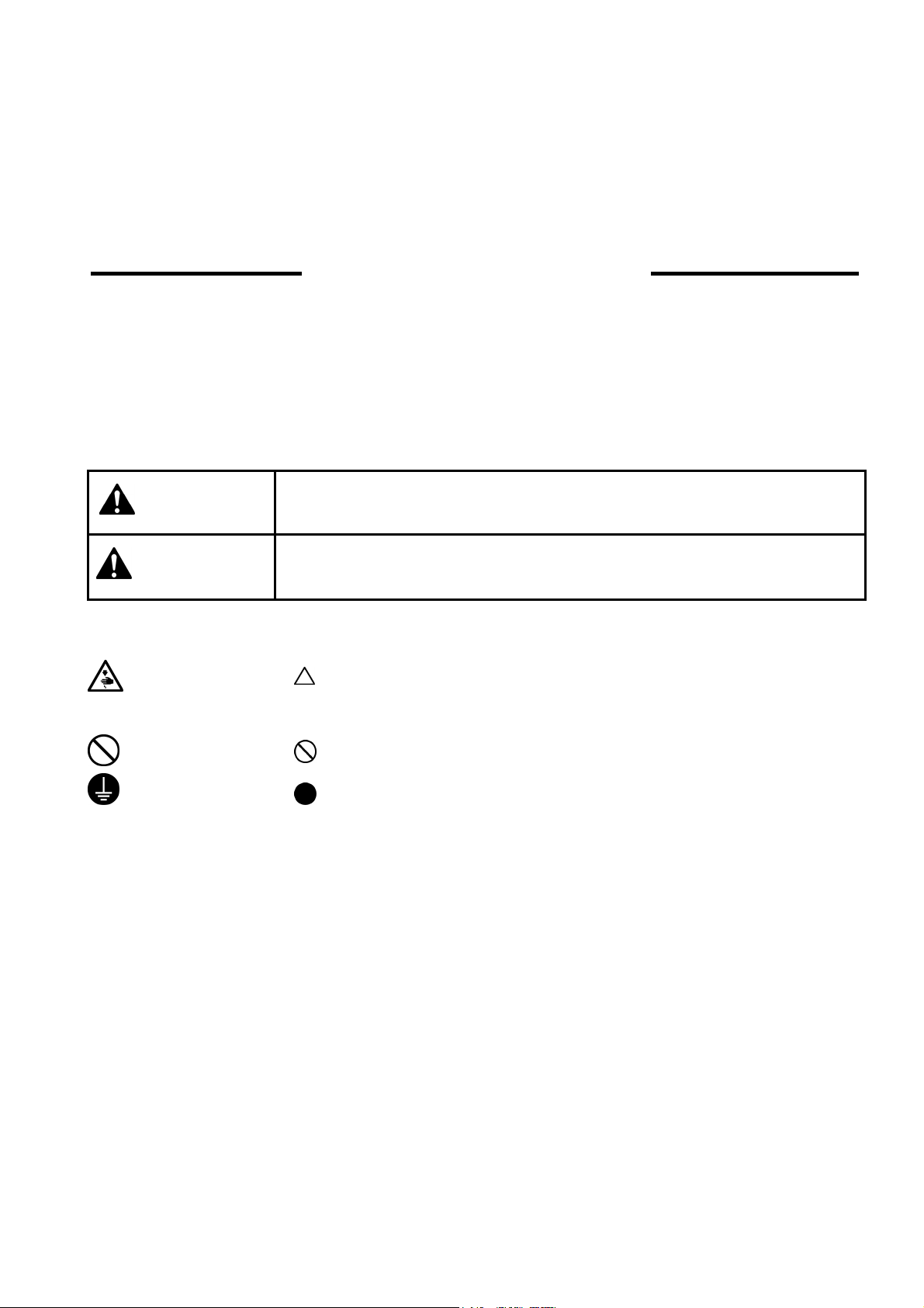
Indications
DANGER
CAUTION
Symbols
-------- This symbol (
The picture inside the triangle indicates the nature of the caution that must be taken. (For
example, the symbol at left means "beware of injury".)
--------- This symbol (
--------- This symbol (
The picture inside the circle indicates the nature of the thing that must be done.
(For example, the symbol at left means "you must make the ground connection".)
The instructions which follow this term indicate situations where failure to
follow the instructions will almost certainly result in death or severe injury.
The instructions which follow this term indicate situations where failure to
follow the instructions could cause in
damage to equipment and surroundings.
) indicates something that you should be careful of.
) indicates something that you must not do.
) indicates something that you must do.
when using the machine or physical
BE-1204B-BC • BE-1206B-BC 1
Page 4

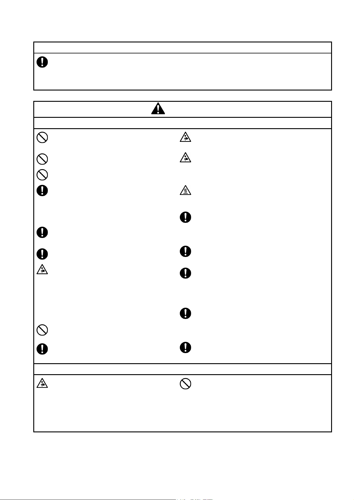
2 Notes on safety
p
g
y
g
Wait at least 5 minutes after turning off the power switch and disconnecting the power cord from the wall
outlet before o
can result in severe injury.
ening the face plate of the control box. Touching areas where high voltages are present
DANGER
CAUTION
Environmental requirements
Use the sewing machine in an area which is
free from sources of strong electrical noise
such as high-frequency welders.
Sources of strong electrical noise may cause
problems with correct operation.
Any fluctuations in the power supply voltage
should be within ±10% of the rated volta
the machine.
Voltage fluctuations which are greater than
this may cause problems with correct
operation.
The power supply capacity should be greater
than the requirements for the sewing
machine's electrical consumption.
Insufficient power supply capacity may cause
problems with correct operation.
The air supply should have a capacity greater
than the machine consumption. If air is not
supplied sufficiently, a machine malfunction
may occur.
e for
Installation
Machine installation should only be carried
out by a qualified technician.
Never operate the sewing machine with any
ventilation openings blocked.
Keep the ventilation openings of the sewing
machine free from the accumulation of lint or
dust.
The ambient temperature should be within the
range of 5°C to 35°C during use.
Temperatures which are lower or higher than this
may cause problems with correct operation.
The relative humidit
45% to 85% during use, and no dew formation
should occur in any devices.
Excessively dry or humid environments and dew
formation may cause problems with correct
operation.
Avoid exposure to direct sunlight during use.
Exposure to direct sunlight may cause problems
with correct operation.
In the event of an electrical storm, turn off the
power and disconnect the power cord from the
wall outlet.
Lightning may cause problems with correct
operation.
Do not use this machine outdoors.
Be sure to connect the ground. If the ground
connection is not secure, you run a high risk of
receiving a serious electric shock, and problems
with correct operation may also occur.
When securing the cords, do not bend the cords
excessively or fasten them too hard with staples,
otherwise there is the danger that fire or electric
shocks could occur.
should be within the range of
Contact your Brother dealer or a qualified
electrician for any electrical work that may
need to be done.
The sewing machine weights more than 700
Kg (600 Kg in four head models).
The installation should be carried out by four
or more people.
Do not connect the power cord until
installation is complete, otherwise the
machine may operate if the start switch is
pressed by mistake, which could result in
injury.
2 BE-1204B-BC • BE-1206B-BC
Be sure to wear protective goggles and gloves
when handlin
no oil or grease gets into your eyes or onto your
skin, otherwise inflammation can result.
Furthermore, do not drink the oil or grease under
any circumstances, as they can cause vomiting
and diarrhoea.
Keep the oil out of the reach of children.
Secure the machine with the adjustment bolts on
the sound floor so that it will not move.
the lubricating oil or grease, so that
Page 5
Avoid setting up the sewing machine near
p
g
sources of strong electrical noise such as
high-frequency welding equipment.
If this precaution is not taken, incorrect
machine operation may result.
Installation
CAUTION
Sewing
This sewing machine should only be used by
operators who have received the necessary
training in safe use beforehand.
Keep children away from the sewing machine.
The sewing machine should not be used for
any applications other than sewing.
Be sure to wear protective goggles when
using the machine.
If goggles are not worn, there is the danger
that if a needle breaks, parts of the broken
needle may enter your eyes and injury may
result.
Always use the proper needle plate. Any
wrong plate can cause needles to break.
Do not use a bent needle.
Turn off the power switch at the following
times, otherwise the machine may operate if
the start switch is pressed by mistake, which
could result in injury.
• When threading the needle
• When replacing the bobbin and needle
• When not using the machine and when
leaving the machine unattended
• When cleaning the machine.
Do not get on the table.
Table may be damaged.
Attach all safety devices before using the sewing
machine. If the machine is used without these
devices attached, injury may result.
Do not touch any moving parts, press any objects
against the machine, or pull/push the cloth during
sewing. Doing so may result in personal injury,
machine damage, or needle breakage.
Do not touch the
bed section during operation or for 30 minutes
after operation. Otherwise burns may result.
Never drop or insert foreign objects or a
screwdriver into the ventilation openings or the
machine inside.
Touching any high-voltage area may result in an
electric shock.
Never damage, alter, heat, or put a strain on the
power cable as well as other cables. Doing so
may result in a fire or an electric shock.
If the controller is exposed to water or a chemical
agent or if its entry is found inside the controller,
turn off the power switch immediately.
Continuing to use the machine under such a
condition may result in a fire or an electric shock.
If an error occurs in machine operation, or if
abnormal noises or smells are noticed,
immediately turn off the power switch. Then
contact your nearest Brother dealer or a qualified
technician.
ulse motor and sewing machine
Do not operate this machine where aerosol
(spray) products are being used or where
oxygen is being administered.
If the machine develops a problem, contact your
nearest Brother dealer or a qualified technician.
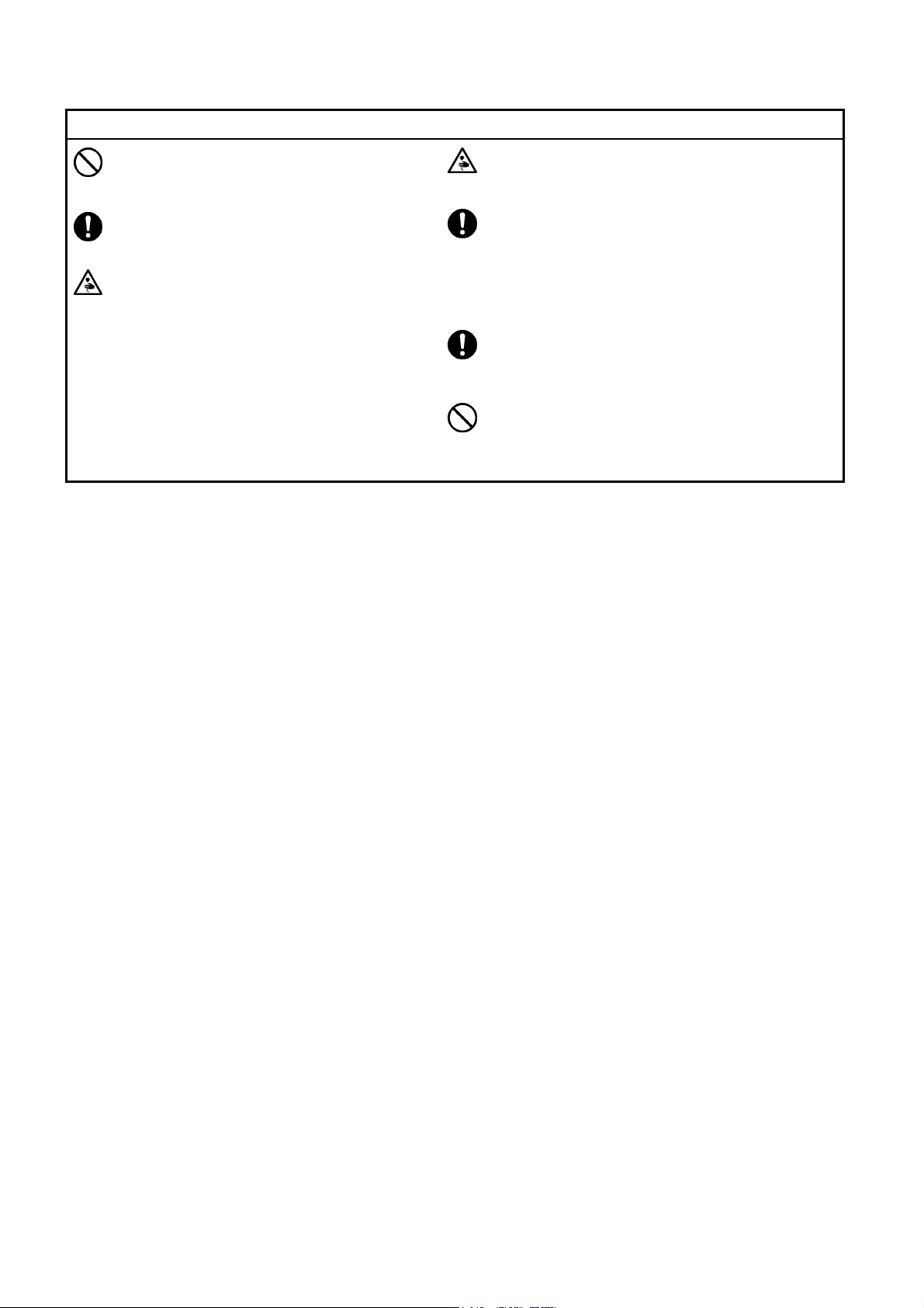
Cleaning
Turn off the power switch before starting any
cleaning work, otherwise the machine may
operate if the start switch is pressed by
mistake, which could result in injury.
BE-1204B-BC • BE-1206B-BC 3
Be sure to wear protective goggles and gloves
when handlin
no oil or grease gets into your eyes or onto your
skin, otherwise inflammation can result.
Furthermore, do not drink the oil or grease under
any circumstances, as they can cause vomiting
and diarrhoea.
Keep the oil out of the reach of children.
the lubricating oil or grease, so that
Page 6
Maintenance and inspection
p
ying
Maintenance and inspection of the sewing
machine should only be carried out by a
qualified technician.
Ask your Brother dealer or a qualified
electrician to carry out any maintenance and
inspection of the electrical system.
Turn off the power switch and disconnect the
power cable (do not pull on the cable itself)
from the wall outlet before attempting to
erform the following operations. Otherwise,
the machine is started if the start switch is
pressed by mistake. Injury may occur in
such a case.
• When carr
or maintenance
• When replacing consumable parts such
as a rotary hook, a knife, or a fluorescent
lamp
out inspection, adjustment,
If the power switch needs to be left on when
carrying out some adjustment, be extremely
careful to observe all safety precautions.
Use only the proper replacement parts as
specified by Brother.
When replacing a fluorescent lamp, use the
same-type lamp having a rating of 40 watts.
Wait until the fluorescent lamp cools off before
replacement. Failure to do so can result in
burns.
If any safety devices have been removed, be
absolutely sure to re-install them to their original
positions and check that they operate correctly
before using the machine.
Any problems in machine operation which result
from unauthorized modifications to the machine
will not be covered by the warranty.
4 BE-1204B-BC • BE-1206B-BC
Page 7
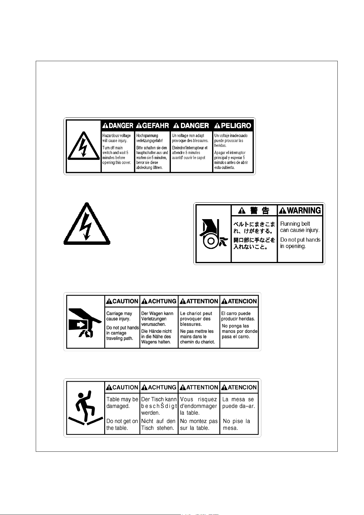
3 Warning labels
* The following warning labels appear on the sewing machine.
Please follow the instructions on the labels at all times when using the machine. If the labels
have been removed or are difficult to read, please contact your nearest Brother dealer.
1 Electric shock danger display
W1408Q
2 Electric shock danger display 3 Injury warning display
Hazardous voltage will
cause injury.
4 Injury caution display
5 Injury caution display
W1410Q
W1200Q
W1202Q
BE-1204B-BC • BE-1206B-BC 5
Page 8
6 Injury caution display
7 Injury caution display
Never touch or push the
thread take up during
operation as it may result in
injuries machine.
Never touch or push the needle
bar during operation as it may
result in injuries or damage to
the sewing machine.
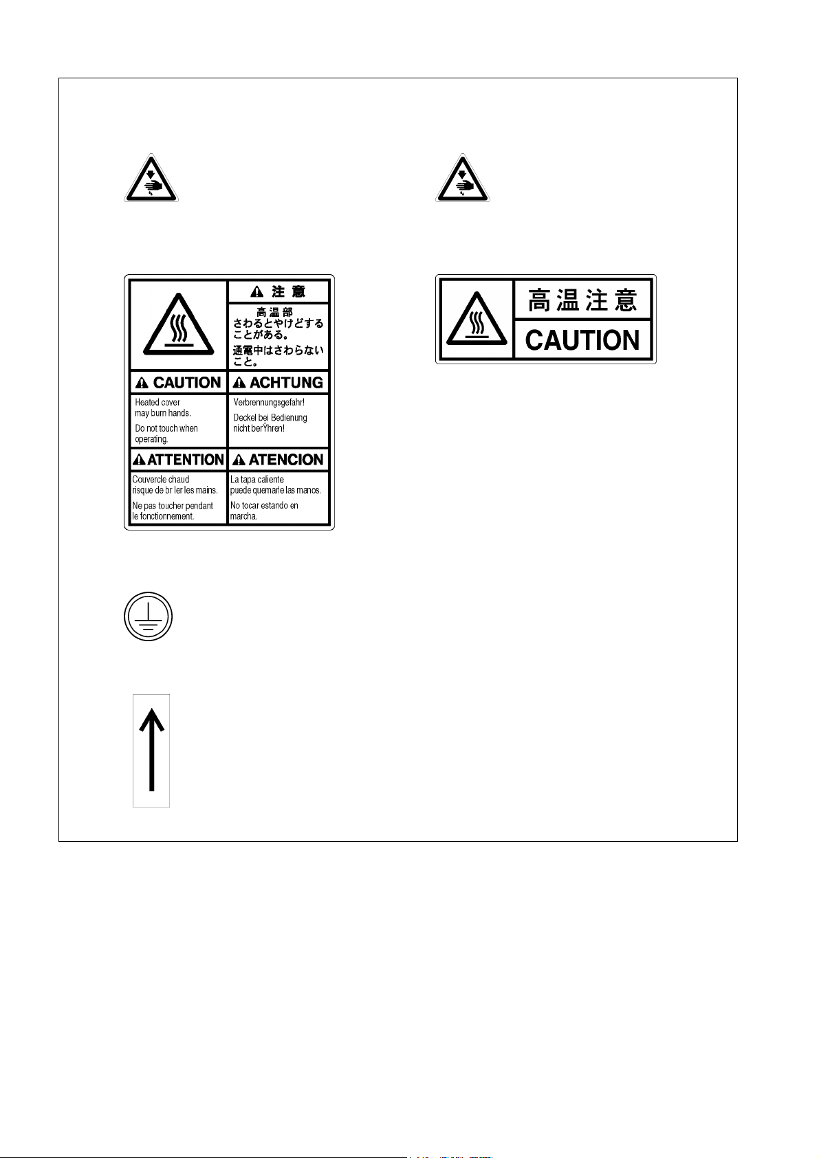
8 High temperature caution display 9 High temperature caution display
W1206Q
Do not touch this part during activitation
or for 30 minutes after shut-off. Otherwise
burns may result.
W1201Q
10 Ground mark
Be sure to connect the ground. If the ground connection is not secure, you run
a high risk of receiving a serious electric shock, and problems with correct
operation may also occur.
11 Direction of operation
W1205Q
6 BE-1204B-BC • BE-1206B-BC
Page 9
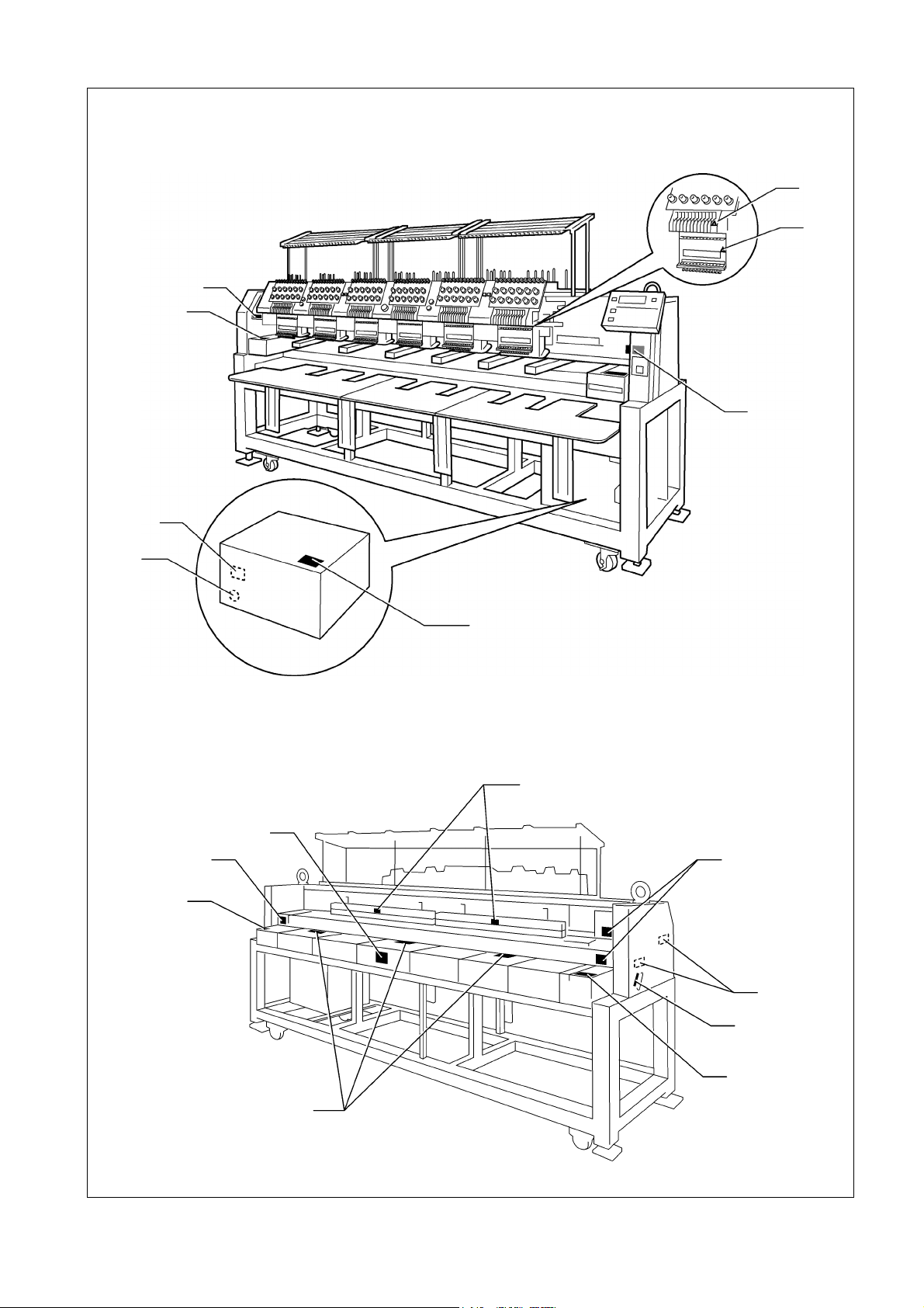
10
6
7
5
4
5
2
1
W1207Q
9
8
8
8
4
3
11
4
4
W1208Q
BE-1204B-BC • BE-1206B-BC 7
Page 10
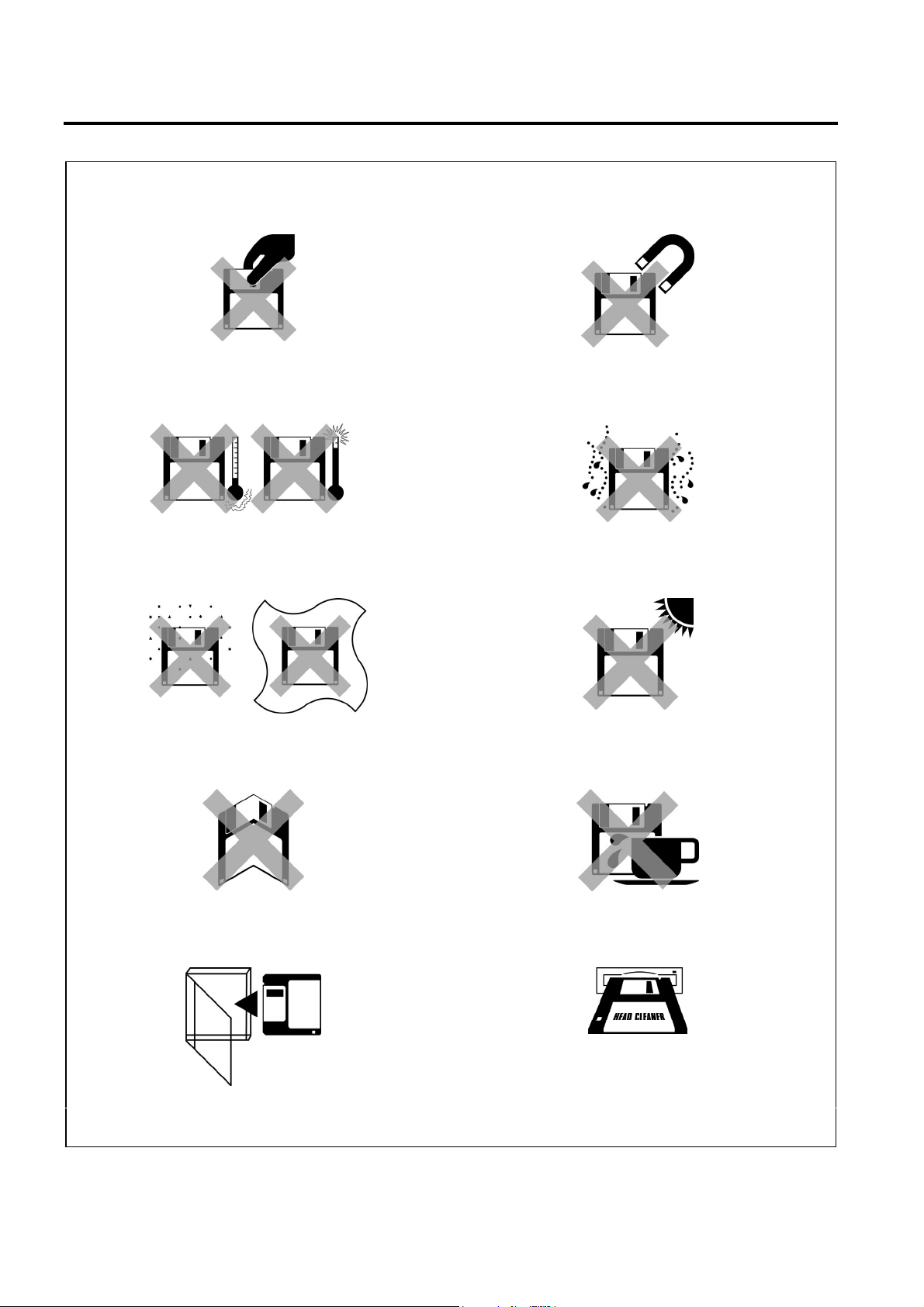
Before Starting Operation
Do not force open the shutter for direct contact
with the magnetic area.
W1209Q
Do not store floppy disks in an extremely high or
low ambient temperature.
W1211Q
Do not use or store floppy disks in a dusty place.
Do not place it on cloth.
Do not bring disks near magnetic matters such as
magnetic screwdriver or the back side of the
programmer.
W1210Q
Do not use floppy disks under high humidity.
W1212Q
Do not store floppy disks under direct sunlight.
W1213Q
Do not bend the disk. Do not put things on the
Avoid contact with solvent or drink.
disk.
W1215Q
Store it in the case immediately after using it to
protect it from dust and damage.
W1217Q
Use a commercially available cleaning disk to clean
the head of the floppy disk drive periodically.
Do not remove the disk out of the drive during the access lamp is lit.
W1214Q
W1216Q
W1218Q
8 BE-1204B-BC • BE-1206B-BC
Page 11
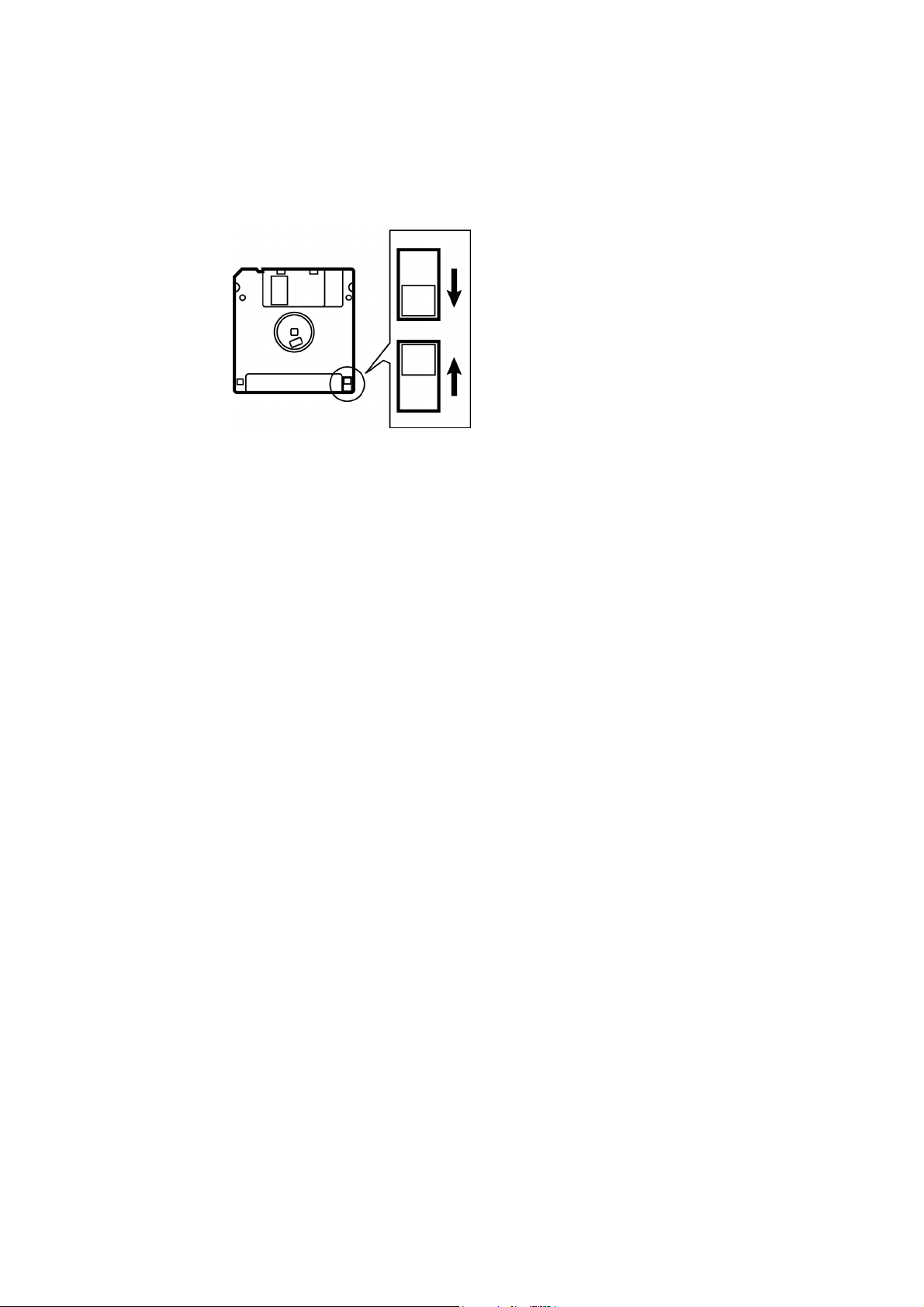
Protecting data in floppy disks
Write-protection is available for a floppy disk to prevent undesired data deletion.
A write-protected disk is read-only. It is recommended to provide write-protection for disks which
contain important data.
To do so, slide the write-protect notch to open the slot as shown below.
Slide the notch in this direction to
prevent data loss or overwriting.
Slide the notch in this direction to
write data.
W1219Q
BE-1204B-BC • BE-1206B-BC 9
Page 12

Procedure of Reading This Manual
Explanation of models
This manual explains two models:
- BE-1204B-BC
- BE-1206B-BC
Explanation for individual model is provided by identifying the model name. Check the model before
using the machine. The display is BE-1206B-BC.
Configuration of this manual
This manual consists of the following chapters:
Chapter 1 Preparation of Embroidery Machine
This Chapter describes the specifications, installation and preparatory procedures of starting up
the machine.
Chapter 2 Embroidering Procedures
Provides explanations on the operation panel and briefly reviews the flow of embroidering
processes.
Chapter 3 Selection of Data and Embroidering
This Chapter describes procedures of reading sewing data and sewing.
Chapter 4 Editing of Embroidering Data
Explains how to edit the embroidery data.
Chapter 5 Setting
This Chapter describes procedures of setting the machine and working environment.
Chapter 6 Operation of Machine
Provides information on machine operation during embroidering.
Chapter 7 Maintenance
Describes appropriate maintenance of the machine.
Chapter 8 Adjustment
Explains how to adjust the needles.
Chapter 9 List of Error Messages
Provides information on error codes and action to be taken.
Chapter 10 Troubleshooting
Provides troubleshooting for the machine.
Chapter 11 Connection and Installation of Optional Equipment
Describes connections between the machine/computer and optional equipment available.
10 BE-1204B-BC • BE-1206B-BC
Page 13

BE-1204B-BC • BE-1206B-BC 11
Page 14
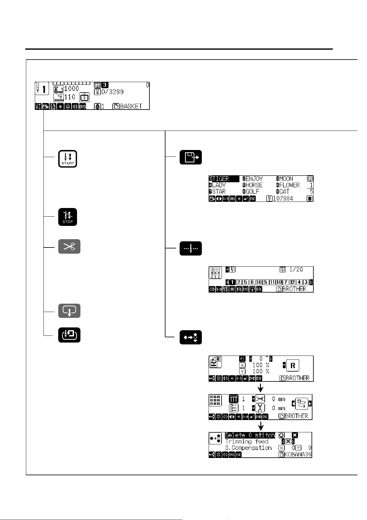
Screen Composition
A
Initial Screen
W0406Q
Starting Sewing
Operation (→ page 3-17)
Canceling of Sewing
Thread trimming
Hoop Retract
Selection of Embroidery data
(→ page 3-3)
W0397Q
Setting of Needle Bars
(→ page 5-4)
W0481Q
rea Check
Editing of Embroidery data
(→ page 4-1)
W0451Q
W0465Q
W0601Q
12 BE-1204B-BC • BE-1206B-BC
Page 15
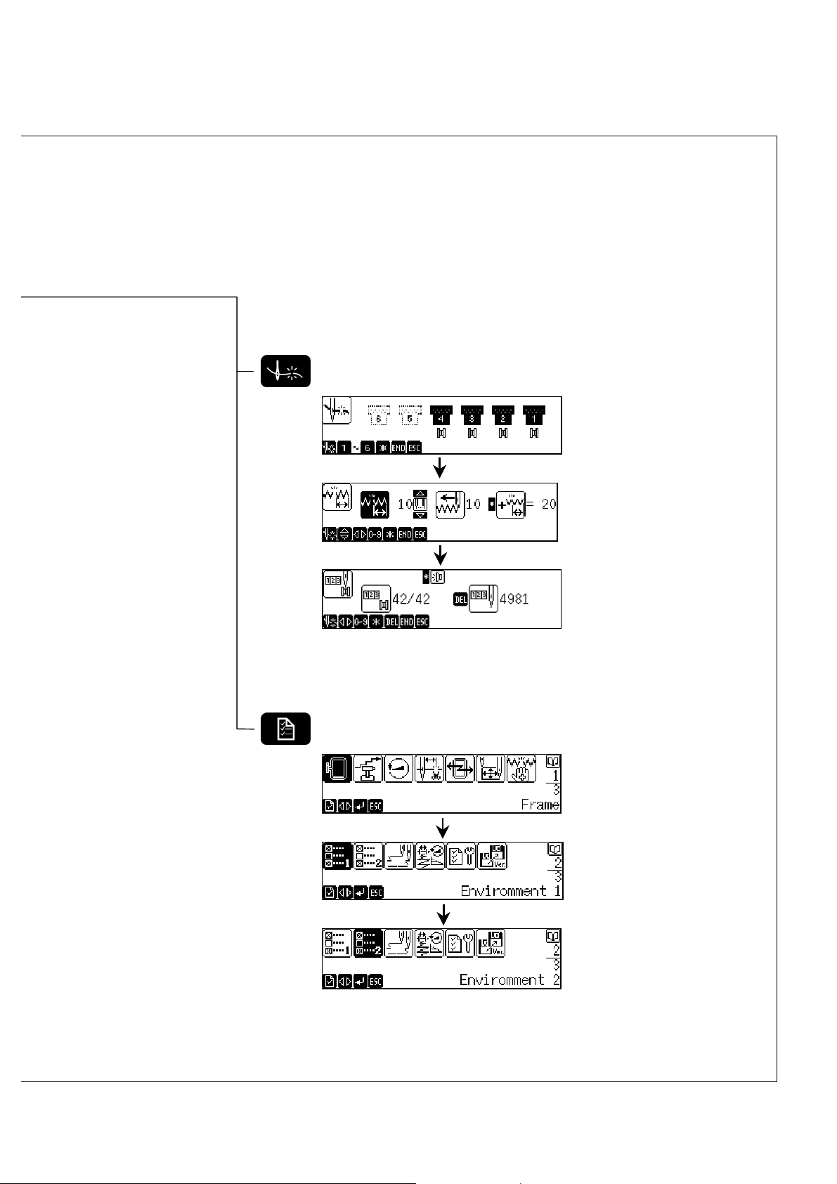
Setting of thread breakage sensor (→ page 5-6)
W0488Q
W0490Q
W0494Q
Setting of Machine (→ page 5-9)
W0609Q
W0620Q
W0621Q
BE-1204B-BC • BE-1206B-BC 13
Page 16

Contents
Contents
SAFETY INSTRUCTIONS................................................................................................................................................. 1
Before Starting Operation ............................................................................................................................................... 8
Procedure of Reading This Manual..............................................................................................................................10
Screen Composition...................................................................................................................................................... 12
Chapter 1 Preparation of Embroidery Machine
1. Specifications ........................................................................................................................................................... 1-2
2. Names of Machine Components ............................................................................................................................. 1-4
3. Installation.................................................................................................................................................................1-5
3-1 Transportation of Machine................................................................................................................................. 1-5
3-2 Installation of Machine.......................................................................................................................................1-7
3-3 Preparation of Needle Bar Case........................................................................................................................1-8
3-4 Mounting of Table .............................................................................................................................................. 1-9
3-5 Mounting of Cotton Stand................................................................................................................................ 1-12
3-6 Lubrication to Needle Bar Case.......................................................................................................................1-13
3-7 Grounding........................................................................................................................................................1-14
4. Preparation for Embroidering................................................................................................................................1-15
4-1 Upper Threading..............................................................................................................................................1-15
4-2 Replacement of Bobbin ................................................................................................................................... 1-17
4-3 Replacing and Selecting Needle......................................................................................................................1-19
4-4 Attachment of Embroidery Hoop and Frame ................................................................................................... 1-20
4-5 Adjustment of Thread Tension ......................................................................................................................... 1-24
Chapter 2 Embroidering Procedures
Functions of Operation Panel......................................................................................................................................2-2
Operation Panel.......................................................................................................................................................2-2
Switches at Machine Heads ....................................................................................................................................2-5
Lamps and switches on the thread tension stand .................................................................................................... 2-6
Flowchart of Preparation for Embroidering ...............................................................................................................2-7
Turn on the Machine Power..................................................................................................................................... 2-8
Retrieve the Embroidery Data ................................................................................................................................. 2-9
Start Embroidering................................................................................................................................................... 2-9
Chapter 3 Selection of Data and Embroidering
What Can the Machine Do? .........................................................................................................................................3-2
Selection of Embroidery Data....................................................................................................................... 3-2
Embroidering Operation...........................................................................................................................................3-2
Selection of Data .......................................................................................................................................................... 3-3
Registration of Embroidery Data from Floppy Disk..................................................................................................3-3
Reading from Memory ............................................................................................................................................. 3-7
Registration of Embroidery Data from BES-100E.................................................................................................... 3-8
Deletion of Embroidery Data from Machine Memory ............................................................................................... 3-9
Tape Reader Input Setting ......................................................................................................................................... 3-11
Modification of Embroidery Data Name....................................................................................................................3-13
Sewing Operation....................................................................................................................................................... 3-17
Before Starting Sewing ..........................................................................................................................................3-17
Starting Sewing Operation..................................................................................................................................... 3-17
Feedhold and Cancellation of Sewing ................................................................................................................... 3-18
Step Forward and Step-Back.....................................................................................................................................3-19
Step Forward/Step-Back Mode.............................................................................................................................. 3-19
Setting Amount or Timing of Step Forward/Step-Back........................................................................................... 3-19
14 BE-1204B-BC • BE-1206B-BC
Page 17
For Step Forward (Back) ........................................................................................................................................3-20
Resuming Sewing ..................................................................................................................................................3-20
Writing the embroidering data ...................................................................................................................................3-21
Chapter 4 Editing of Embroidering Data
What Can the Machine Do?..........................................................................................................................................4-2
Editing.............................................................................................................................................................4-2
Rotation .........................................................................................................................................................................4-3
Enlargement and Reduction ........................................................................................................................................4-4
Mirror .............................................................................................................................................................................4-6
Repetition ......................................................................................................................................................................4-8
Other Editing ...............................................................................................................................................................4-10
Chapter 5 Setting
What Can the Machine Do?..........................................................................................................................................5-2
Setting of Needle Bars..................................................................................................................................5-2
Setting of Thread Breakage Sensor .............................................................................................................5-2
Setting of Machine........................................................................................................................................5-2
Setting of Environment .................................................................................................................................5-2
Setting of Lock Stitch ......................................................................................................................................5-3
Setting of speed limit in a small pitch..............................................................................................................5-3
Display of Information...................................................................................................................................5-3
Hoop Retract Point .......................................................................................................................................5-3
Hoop Movement.......................................................................................................................................................5-3
Setting of Needle Bars..................................................................................................................................................5-4
Thread Breakage Sensor..............................................................................................................................................5-6
Setting of sensor validity/invalidity............................................................................................................................5-6
Thread Breakage Sensitivity ....................................................................................................................................5-6
Automatic Step-Back................................................................................................................................................5-7
Setting of Lower Thread Counter/Stitch Counter......................................................................................................5-8
Setting of Machine........................................................................................................................................................5-9
Embroidery Hoop .....................................................................................................................................................5-9
Speed Range .........................................................................................................................................................5-10
Speed of Each Speed Range................................................................................................................................. 5-11
Setting of Mending .................................................................................................................................................5-12
Thread Trimming Length ........................................................................................................................................5-14
Thread Withdrawal Feed Length ............................................................................................................................5-15
Inching ...................................................................................................................................................................5-16
Sewing Area...........................................................................................................................................................5-17
Registration of Sewing Start Position .....................................................................................................................5-18
Hoop Retract Point.................................................................................................................................................5-18
Hoop Automatic Retract .........................................................................................................................................5-19
Movement to Registered Sewing Start Point..........................................................................................................5-19
Setting of Environment ..............................................................................................................................................5-20
Return to Start Point...............................................................................................................................................5-20
Speed Range .........................................................................................................................................................5-21
Checking the Embroidery Area ..............................................................................................................................5-21
Slow sewing needle number at start-up .................................................................................................................5-22
Setting of RS-232C Communication Speed ...........................................................................................................5-23
Display Language ..................................................................................................................................................5-24
Alarm Sound ..........................................................................................................................................................5-25
Motive Speed .........................................................................................................................................................5-26
Small-Pitch Deletion...............................................................................................................................................5-27
Automatic pause insertion......................................................................................................................................5-28
Contents
BE-1204B-BC • BE-1206B-BC 15
Page 18

Contents
Lock Stitch ............................................................................................................................................................. 5-29
Speed Limit in a Short Pitch...................................................................................................................................5-32
Feed Timing...........................................................................................................................................................5-33
Automatic Input Setting..........................................................................................................................................5-34
Display of Information................................................................................................................................................5-37
Pattern Information ................................................................................................................................................ 5-37
Features of Machine.............................................................................................................................................. 5-38
Information about Versions .................................................................................................................................... 5-39
Chapter 6 Operation of Machine
1. Operating Procedures.............................................................................................................................................. 6-2
1-1 Power Source....................................................................................................................................................6-2
1-2 Preparation for Embroidering............................................................................................................................. 6-2
2. Machine Stop ............................................................................................................................................................ 6-3
2-1 Stopping the Machine........................................................................................................................................ 6-3
2-2 Emergency Stop of the Machine........................................................................................................................6-3
2-3 Resetting Emergency Stop ................................................................................................................................ 6-3
3. Measures against Thread Breakage .......................................................................................................................6-4
3-1 Remedies ..........................................................................................................................................................6-4
3-2 Mending.............................................................................................................................................................6-5
4. Jog Embroidering..................................................................................................................................................... 6-7
5. Hoop Feed Position.................................................................................................................................................. 6-8
6. Area Check................................................................................................................................................................ 6-9
6-1 External Tracing.................................................................................................................................................6-9
6-2 Automatic Hoop Movement in Area ................................................................................................................... 6-9
7. Jog Switches...........................................................................................................................................................6-10
7-1 Hoop Movement to Start Position .................................................................................................................... 6-10
7-2 Inching Mode during Embroidering (Forcible Hoop Movement) ...................................................................... 6-11
8. Detection of Home position................................................................................................................................... 6-12
Chapter 7 Maintenance
1. Cleaning .................................................................................................................................................................... 7-2
1-1 Cleaning and Lubrication of Rotary Hook .......................................................................................................... 7-2
1-2 Cleaning of Needle Plate................................................................................................................................... 7-3
2. Oiling .........................................................................................................................................................................7-4
2-1 Head.................................................................................................................................................................. 7-4
2-2 Lower shaft........................................................................................................................................................ 7-5
3. Greasing....................................................................................................................................................................7-6
3-1 Cam grooves ..................................................................................................................................................... 7-6
3-2 Lower gear ........................................................................................................................................................7-8
3-3 Diving shaft........................................................................................................................................................7-8
3-4 Needle bar flip-up mechanism........................................................................................................................... 7-9
3-5 Feed Guide Section.........................................................................................................................................7-10
16 BE-1204B-BC • BE-1206B-BC
Page 19

Chapter 8 Adjustment
1. Adjusting Needle Bar Height....................................................................................................................................8-2
2. Attachment and Adjustment of Rotary Hook ..........................................................................................................8-6
3. Adjustment of Presser Foot Height .........................................................................................................................8-8
4. Adjustment of Thread Trimmer ................................................................................................................................8-9
4-1 Attaching the Fixed Knife ...................................................................................................................................8-9
4-2 Checking the Movable Knife Position.................................................................................................................8-9
5. Thread Wiper Adjustment ......................................................................................................................................8-12
Chapter 9 Error code list
Chapter 10 Troubleshooting
Mechanical Section.....................................................................................................................................................10-2
Electrical Section........................................................................................................................................................10-4
Chapter 11 Connection and Installation of Optional Equipment
1. Attaching Bobbin Winder .......................................................................................................................................11-2
Contents
BE-1204B-BC • BE-1206B-BC 17
Page 20

Contents
18 BE-1204B-BC • BE-1206B-BC
Page 21

Chapter 1
Preparation of Embroidery Machine
Page 22

Chapter 1 Preparations of operation
1. Specifications
Embroidery machine used
Application Pattern embroidery
Sewing speed Maximum 1000 rpm
Distance between heads 360 mm
Maximum feed range
Sewing area
Feed system By timing belt and stepping motor drive
Stitch length 0.1 ~ 12.7 mm (minimum pitch: 0.1 mm)
Storage medium
Thread trimming Automatic thread trimmer
Thread breakage detect Upper and lower thread breakage detector
Power supply
Weight 700 kg 600kg
Dimensions
Options Embroidery hoops in different sizes, Bobbin winder
12 needle six-head embroidery
machine
450 (V) × 360 (H) mm
95 (V) × 360 (H) mm (With cap frame)
450 (V) × 360 (H) mm (With sash frame)
430 (V) × 300 (H) mm (With maximum-size tubular square hoop/flat hoop)
85 (V) × 360 (H) mm (With cap frame)
3.5 2DD floppy disk (Tajima format)
3.5 2HD floppy disk (the equivalent to Tajima format)
3.5 2DD floppy disk (Barudan FDR/FMC format)
3.5 2DD floppy disk (ZSK format)
3.5 floppy disk (brother ECS format)
Single phase 200 V, 220 V, 230 V, 240 V,1.7 kVA
Flourescent lamp: 92VA 49W (Maximum)
(Before assembly)
3036 (W) × 800 (L) × 1405 (H) mm
(After setup)
3112 (W) × 1345 (L) × 1750 (H) mm
12 needle four-head embroidery
machine
(Before assembly)
2320 (W) × 800 (L) × 1405 (H) mm
(After setup)
2396 (W) × 1345 (L) × 1750 (H) mm
1-2 BE-1204B-BC • BE-1206B-BC
Page 23

Accessories
Chapter 1 Preparations of operation
Standard Accessories Optional Accessories
Embroidery hoop
• Tubular square hoop 26 × 43
(6 head: 6, 4 head: 4)
• Tubular round arm set
• Holder base 30 × 43
(6 head: 6, 4 head: 4)
Other embroidery hoops in different sizes
(6 head: 7, 4 head: 5)
• Sash frame assembly
* Other Tajima embroidery hoops that can
be used with BAS-412A and BES-916AC
• Cap frame (6 head: 6, 4 head: 4)
Cap frame drive assembly
(6 head: 6, 4 head: 4)
Base frame set
(6 head: 12, 4 head: 8)
Set frame base set (1)
Others Table assembly • Bobbin winder
BE-1204B-BC • BE-1206B-BC 1-3
Page 24
Chapter 1 Preparations of operation
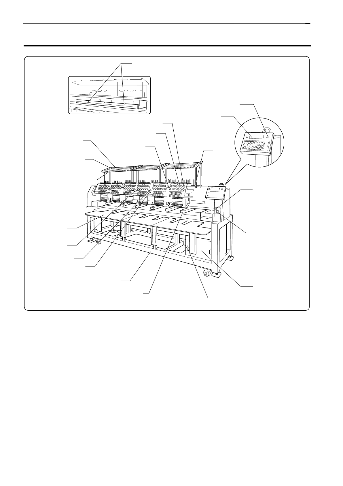
2. Names of Machine Components
Fluorescent lamp switch
Flat / Cap hoop select switch
Operation panel
Thread tension dial
Thread tension base switch
Thread guide C
STEP BACK /
FWD switch
Thread guide B
Thread guide A
Cotton
stand
Fluorescent lamp
switch
Table
Emergency stop
switch
Start switch
Stop switch
Leg
Rotary hook cover (Safety device)
Main power switch
Power switch
Control box
The machine heads are numbered 1 to 6 (1 to 4 in four head models) from the right front.
W1220Q
1-4 BE-1204B-BC • BE-1206B-BC
Page 25
3. Installation
y
q
Chapter 1 Preparations of operation
DANGER
Embroidery machines should be installed onl
by trained engineers.
Electric wiring should be laid by your
distributor or electric experts.
The sewing machine weights more than
700 Kg (600 Kg in four head models).
The installation should be carried out by four
or more people.
Do not connect the power source until
installation is completed. Doing so may start
the machine unintentionally through an
accidental activation of the START switch,
resulting in bodily injuries.
Install a machine in a place away from a highfre
uency welding machine or other machines that
may generate a strong electric noise. Failure to
do so may cause the embroidery machine to
malfunction.
Be sure to connect the ground. If the ground
connection is not secure, you run a high risk of
receiving a serious electric shock, and problems
with correct operation may also occur.
Secure the machine with the adjustment bolts on
the sound floor so that it will not move.
After installation is completed, get the power supply from a dedicated outlet.
When connecting multiple machines, exercise care not to exceed the capacity of the outlet.
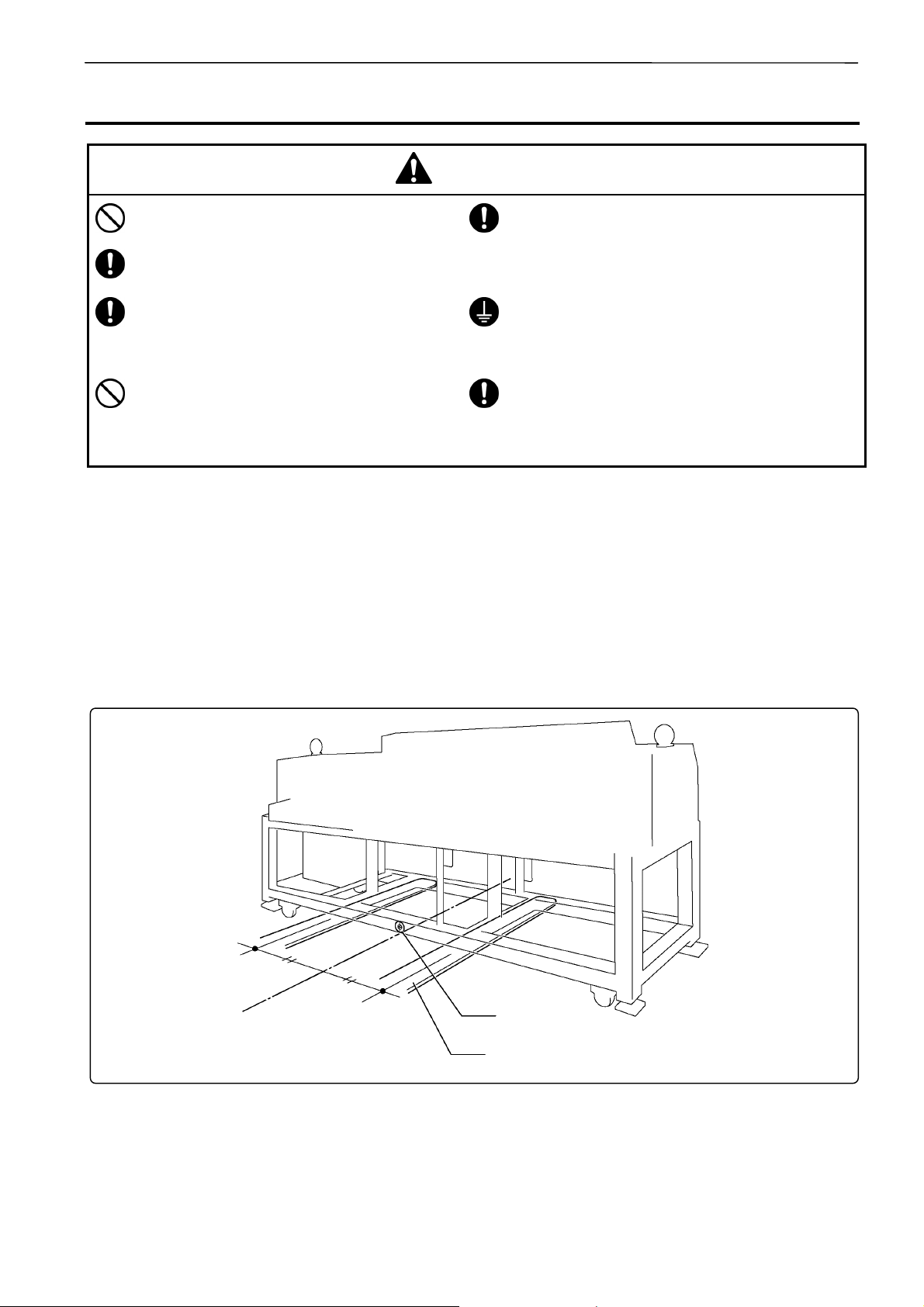
3-1 Transportation of Machine
When relocating the machine, push the steel frame. Never push the cover or carriage.
!!!! When using a fork lift
The central seal
Lift forks
W1222Q
1. Viewing the machine from the back, position their center at the central seal, insert the forks under
the legs and lift the machine.
BE-1204B-BC • BE-1206B-BC 1-5
Page 26
Chapter 1 Preparations of operation
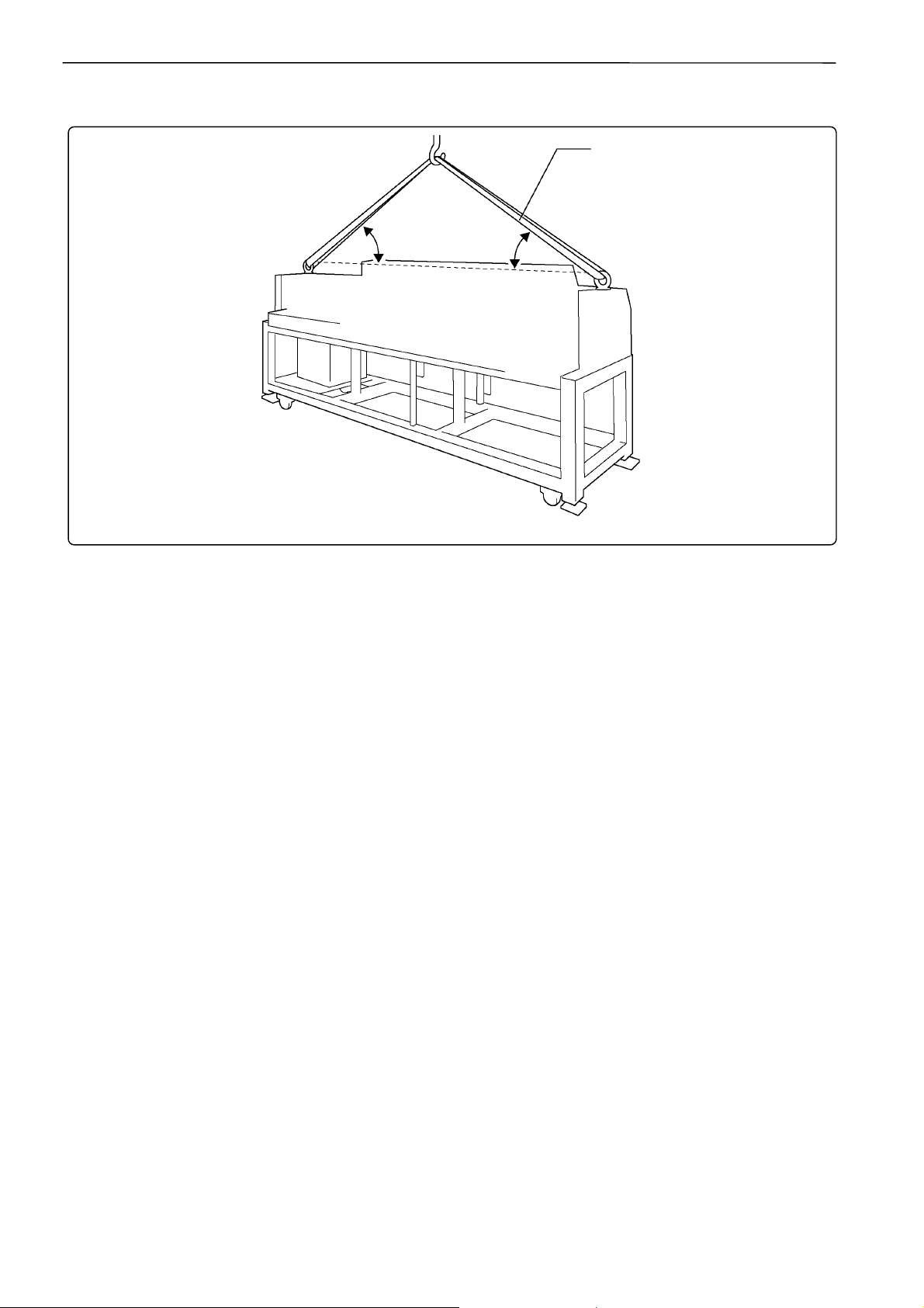
!!!! When using a crane
Belt
More than
45°
More than
45°
W1223Q
2. Hook on the eyebolts with each belt to lift up the machine.
When lifting the machine, make sure that the belts do not contact the machine table or the tension
plate.
1-6 BE-1204B-BC • BE-1206B-BC
Page 27
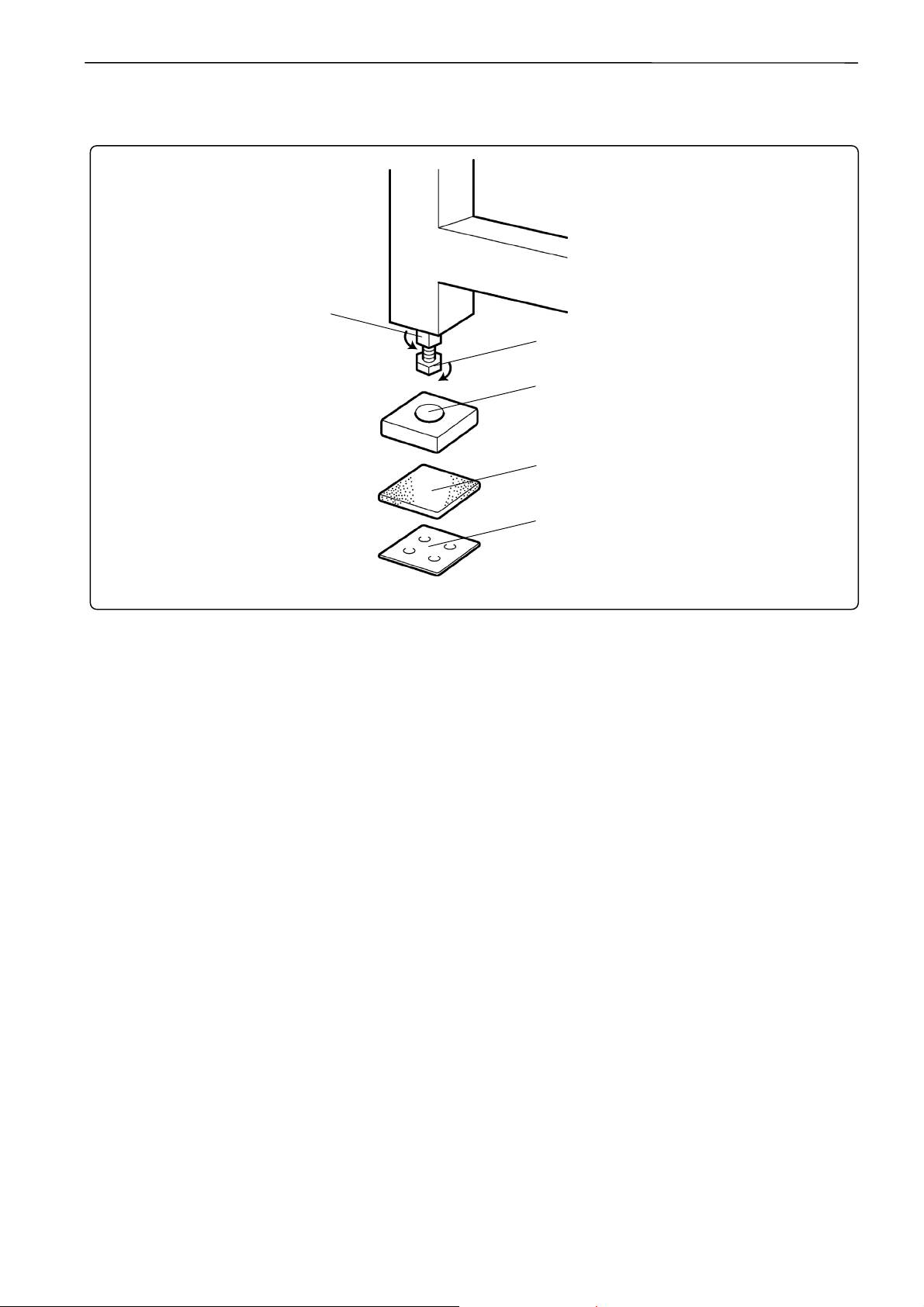
3-2 Installation of Machine
[5]
Chapter 1 Preparations of operation
[1]
[4]
[3]
[2]
W1224Q
1. Place Footboard [4], a rubber cushion 10 [3] (provided with the machine), and PE sheet [2] under
each of four adjustment bolts M20 [1]. The Footboard must be on the rubber cushion.
2. Fit four adjustment bolts M20 [1] into the hole of Footboard [4], and adjust the embroidery machine
in height.
The adjustment must be made in such a manner that the four bolts are under an equal load when
the machine is placed down. (To lower adjustment bolt M20 [1], turn it in the direction of the arrow.)
Also, the casters should be raised.
3. After adjusting four adjustment bolts M20 [1], turn nuts M20 [5] in the direction of the arrow to
fasten them.
If the floor is not strong enough, the embroidery machine may be rocked during operation. In such a
case, it is recommended that a secure base of concrete be placed below the embroidery machine.
BE-1204B-BC • BE-1206B-BC 1-7
Page 28
Chapter 1 Preparations of operation
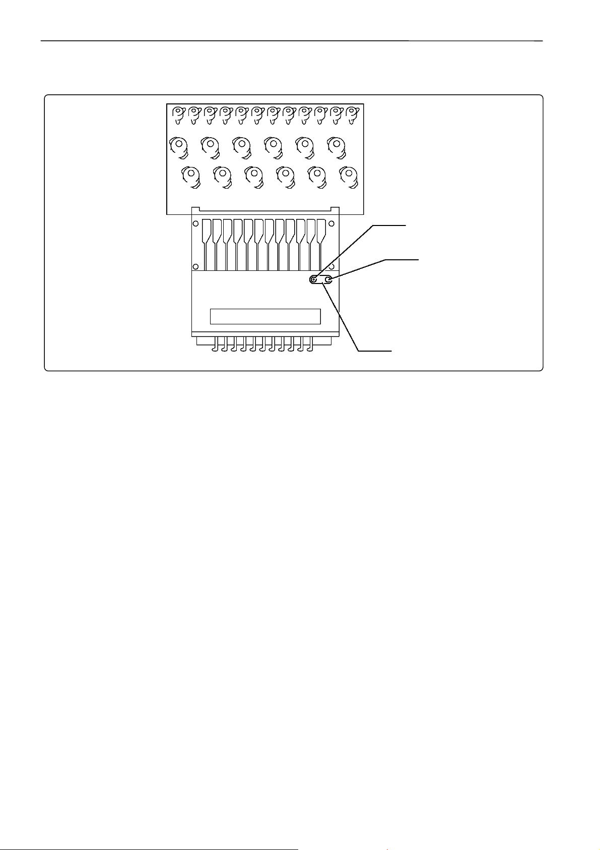
3-3 Preparation of Needle Bar Case
[1]
[2]
Repeat the procedures below for all the heads:
1. Unscrew the screw [1], then detach the bracket [3] and pin [2].
[3]
W1225Q
1-8 BE-1204B-BC • BE-1206B-BC
Page 29
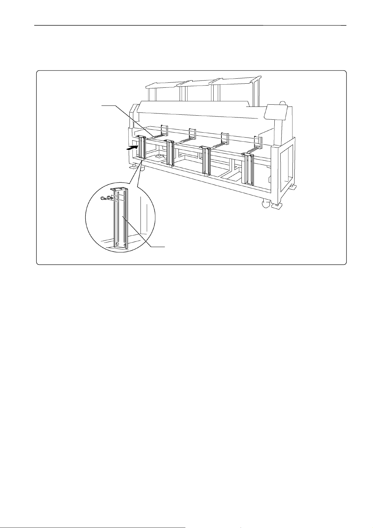
3-4 Mounting of Table
!!!! Preparation for mounting the table
Table guide bridge
Chapter 1 Preparations of operation
[1]
W1226Q
• This operation is required only when the table set is purchased separately from the machine.
• The table is a standard attachment.
1. Tentatively mount 4 (3 in four-head models) table supports Front [1] on the leg front using 4 bolts
each.
BE-1204B-BC • BE-1206B-BC 1-9
Page 30
Chapter 1 Preparations of operation
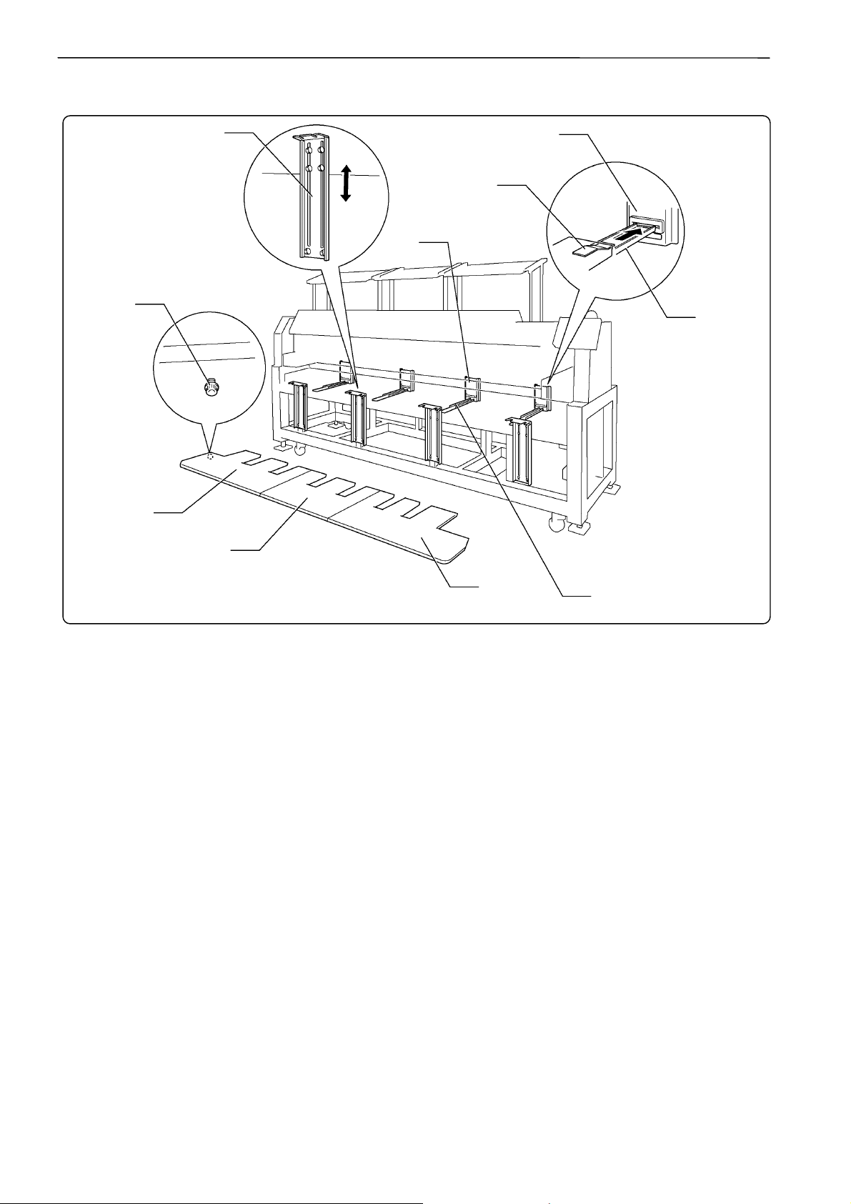
!!!! For embroidering with tubular square hoop or cap frame (lower position)
[8]
[3]
[7]
[6]
[4]
[6]
[5]
[2]
[1]
[5]
W1227Q
1. Attach four hexagon socket head cap screws to each of table parts R [1], M [2](six head models
only), and L [3] from the back.
2. Put the table backing plate [4] of each table on to the table guide bridge [5], and slide to the other
side. Insert the table backing plate [4] into the table backing rubber on the table support Rear [6].
3. Adjust table supports front [7] in height so as to make the table parallel with the floor.
4. Tighten all hexagon socket head cap screws [8] firmly.
1-10 BE-1204B-BC • BE-1206B-BC
Page 31

!!!! For embroidering with flat hoop/sash frame (upper position)
[5]
[4]
[2]
[3]
Chapter 1 Preparations of operation
[1]
[7]
[6]
W1228Q
1. Attach four hexagon socket head cap screws to each of table parts R [1], M [2](six head models
only), and L [3] from the back.
2. Insert the table backing plate [4] of each table into the table backing rubber on the table support
Middle [5].
3. Adjust the height of the table support Front [6] to be even with the upper surface of the bed.
4. Tighten all hexagon socket head cap screws firmly.
5. Attach four(three in four head models) thumb bolts to the lower front steel pipe of the leg section.
Fasten the table and the leg section using table stays (4 pcs(3pcs in four head models)) [7].
BE-1204B-BC • BE-1206B-BC 1-11
Page 32

Chapter 1 Preparations of operation
3-5 Mounting of Cotton Stand
Thread guide A
Thread guide B
Thread guide C
[5]
Front
[1]
[2]
[4]
[3]
[6]
W1229Q
1. Attach the cotton stand bars[2] to the cotton stand assembly[1].
2. Attach four thread guide support bars [3] to the cotton stand assembly [1], while fitting into the four
holes.
3. Mount the thread guide assembly [4] on the thread guide support bars [3] using the four screws
[5].
•When mounting, use one flat washer [6] below the thread guide support bar [3].
•Pay careful attention to the front and back directions of the thread guides (A, B, C).
1-12 BE-1204B-BC • BE-1206B-BC
Page 33

Chapter 1 Preparations of operation
3-6 Lubrication to Needle Bar Case
Proper lubrication is necessary for keeping the machine head in good condition.
CAUTION
Turn off the power switch before starting any cleaning work, otherwise the machine may operate if the
start switch is pressed by mistake, which could result in injury.
W1221Q
Before operating the machine for the first time after unpacking or after leaving the machine without
operation for a long period of time, supply one or two drops of oil to each needle bar from the oil supply
holes of the lower cover.
• Use the Brother’s specified oil (Nippon Oil, Embroidery Lube 10N; VG10) for this.
• Supplying an excessive amount of oil will cause dripping onto the material.
BE-1204B-BC • BE-1206B-BC 1-13
Page 34

Chapter 1 Preparations of operation
3-7 Grounding
Perform a grounding cable connection. Failure to do so may result in electric shock or machine
malfunction.
CAUTION
Grounding cable
W1231Q
When connecting the power supply, make sure to connect it to the grounding cable (with green and yellow
stripes). When plugging in the outlet, use a plug suited to the outlet.
1-14 BE-1204B-BC • BE-1206B-BC
Page 35

4. Preparation for Embroidering
CAUTION
Turn off the power switch before starting preparation.
Failure to do so may start the machine unintentionally through an accidental activation of the START
switch, resulting in bodily injuries.
4-1 Upper Threading
Chapter 1 Preparations of operation
[3]
Ten si on
stand inner
thread guide
[1]
[2]
Thread Guide
tension disc
Rotary
disc
[4]
Tension stand lower
thread guide
Inner thread guide
[5]
Lower thread
guide
Needle bar
No.3, 6, 9, 12
No.2, 5, 8, 11
No.1, 4, 7, 10
Spring
[6]
Needle bar
thread guide
Pressure foot
W1232Q W1233Q
BE-1204B-BC • BE-1206B-BC 1-15
Page 36

Chapter 1 Preparations of operation
1. Pass an upper thread from the cotton stand through the hole of the thread guide right above each
cotton stand bar. Pass the thread from the back to the front hole.
The cotton stand (top view)
Pass a thread in the order
indicated in the figure.
Front
W1234Q
2. Pass the thread through the upper hole of the pretension[1]. Push up the thread guide tension
disc with your finger, and pass it from the left to the lower hole.
3. Pass the thread through the upper hole of the 2nd pretension. Push up the thread guide tension
disc[2] with your finger, and pass it from the left to the lower hole.
4. Wind the thread clockwise once around the rotary disc and place it on the spring.
5. Pass the thread through the hole of tension stand inner thread guide [3].
6. After passing the thread through the hole of tension stand lower thread guide [4], insert the thread
into the right side of the inner thread guide and pass it through the hole of the thread take-up.
7. Bring the thread back to the inner thread guide. Insert the thread into the hole from the upper
section.
8. Pass the thread through the hole of the wire of the needle bar thread guide [6] and pass it through
the needle eye. Pass it through the presser foot. Pass it to presser spring at the front of lower
thread guide [5].
1-16 BE-1204B-BC • BE-1206B-BC
Page 37

4-2 Replacement of Bobbin
Remove dust, lint and oil from the bobbin case before replacement.
!!!! Removing bobbin case
[2]
[1]
[3]
Chapter 1 Preparations of operation
W1235Q
1. Open the rotary hook cover [1].
2. Hold the knob [2] and take out the bobbin case.
3. Close the knob and take out the bobbin [3].
!!!! Replacing bobbin
Pull out by
about 50 mm
[4]
[5]
[5]
W1238Q W1239Q W1240Q
1. Put a new bobbin in the bobbin case.
Check the winding direction.
Check that the bobbin is pushed out of the bobbin case by about 0.5 mm. If not, the slip prevention
spring of the bobbin case does not work. Adjust the height of the spring or replace it with a new one.
[6]
Bobbin
0.5mm
W1237Q
BE-1204B-BC • BE-1206B-BC 1-17
Page 38

Chapter 1 Preparations of operation
2. Slide the thread under the tension spring [5] through the notch [4].
3. Pull out the thread from the hole of the tension spring [5].
4. Pull out the thread by about 50 mm.
5. Pass the thread through the thread guide [6].
!!!! Attaching bobbin case
[2]
[1]
1. Hold the knob [2] and attach the bobbin case securely.
2. Close the rotary hook cover [1].
W1241Q
1-18 BE-1204B-BC • BE-1206B-BC
Page 39

4-3 Replacing and Selecting Needle
* Relationship between materials and needles
Material Needle Needle thickness
Chapter 1 Preparations of operation
Denim
Leather
Handkerchief #9, #10
Shirt
Towe l
DB × K5
#14,
#16, #18
#11,
#12, #13
!!!! Selecting needle
• When using special threads such as gold, silver, and rame yarn, use a heavy-duty needle (#11~
#16). For better finish, paste the waxed paper on the back of the material.
• In general, use DB×K5 #11 ~ #18 according to the material thickness. For knitted materials, use
DB×K23 #11 because its rounded point prevents the knit thread from breaking.
[1]
[2]
W1242Q
!!!! Removing needle
Loosen the set screw [1] and remove the needle [2].
!!!! Attaching needle
With the flat side facing the front, insert the needle all the way until it meets the end of the needle bar.
Tighten the set screw [1] firmly.
• Set the needle so that the notched part will come on the rotary hook side.
• The needle should not be angled to the left (when viewed from the front).
BE-1204B-BC • BE-1206B-BC 1-19
Page 40

Chapter 1 Preparations of operation
4-4 Attachment of Embroidery Hoop and Frame
!!!! Tubular square hoop
[4]
[3]
[1]
[2]
[5]
W1243Q
1. Loosen the thumb bolt M6 [1] to draw it to the center.
2. Align the positioning hole on the tubular round arm frame [4] with the positioning pin [3] (S58665)
on the X-feed sash [5] (S58650), and fit the tubular round arm fixing nut [2] on the back side of the
thumb bolt M6 [1] into the hole on the X-feed sash.
3. While keeping the nut in the hole, slide the thumb bolt M6 toward the edge and tighten it firmly at
the outermost point.
1-20 BE-1204B-BC • BE-1206B-BC
Page 41

!!!! Holder base (optional)
Y
Chapter 1 Preparations of operation
[8]
[1]
[10]
[5]
[9]
[12]
[7]
Table
Felt
[9]
[11]
[1] [3]
-axis cover
1mm 1mm
[2]
[4]
[6]
[3]
W1244Q
Attaching the holder base frame
1. Set the table. (Refer to “Mounting of Table” on page 1-9.)
2. Insert the frame connecting plate F [4] into the holder base frame L [1], flat frame C6-360 [2] and
holder base frame R [3], using bolts and washers.
3. Attach the flat frame S connecting plates L [5] and R [6] to the holder base frames L [1] and R [3].
4. Attach the flat frame S6-360 set [7] to the flat frame S connecting plates L [5] and R [6], using bolts
of 4×12 and washers of middle 4.
5. Remove 4 bolts [9] from the front of X-feed sash [8].
6. Put the frame connecting plates L [10] and R [11] on the X-feed sash [8]. Fix them with bolts and
washers.
7. Check that the clearance between the mounted flat frame C6-360 [2] and the table is even when
viewed from the machine front.
If adjustments are needed, loosen bolts of the F table support Front [12] and move it in the
direction of the arrow.
8. Tighten each bolt securely after the adjustment is completed.
BE-1204B-BC • BE-1206B-BC 1-21
Page 42

Chapter 1 Preparations of operation
Attaching the holder base
1. Mount the holder base vertically to the X-axis feed sash [1] and flat frame C6-360 [2] using the
thumb bolts [3].
[3]
[1]
[3]
[2]
W1246Q
1-22 BE-1204B-BC • BE-1206B-BC
Page 43

!!!! Sash frame (optional)
[4]
[1]
Chapter 1 Preparations of operation
[2]
[1]
[3]
[5]
[6]
[3]
[4]
[5]
[6]
[3]
[3]
W1247Q
Attaching the sash frame
1. Set the table. (Refer to "3-4 Mounting of Table" (Page 1-9) for details.)
2. Mount two vertical sash frames [1] on the holder base frames L and R, and two horizontal sash
frames [2] on the X-axis feed sash [3] and the holder base frame C6-360 [4], using the screws.
3. Set the material. Then set sash clips 290 [5] horizontally and set sash clips 220 [6] vertically.
Six head models: Sash clips 290 12 units, sash clips 220 10 units
Four head models: Sash clips 290 10 units, sash clips 220 6 units
BE-1204B-BC • BE-1206B-BC 1-23
Page 44

Chapter 1 Preparations of operation
4-5 Adjustment of Thread Tension
!!!! Adjustment of upper thread
0.8~1.4N
Upper stitch width
Upper
thread
Lower
W1248Q W1249Q
Lower stitch width
Adjust upper thread tension to 0.8~1.4N when the thread is pulled at the needle bar thread guide.
* Correct adjustment
thread
Turn the upper thread tension dial so that the needle thread can be pulled to the back of the material
and that the lower stitch width will be about 1/3 of the upper stitch width.
!!!! Adjustment of tension spring
[1]
6~8mm
14mm
[2]
0.2~0.3N
[3]
W1250Q
1. The standard height of the tension spring is the point from where the upper thread comes down by
about 14 mm when it is pulled with certain tension which does not pull out the thread.
2. The standard force of the tension spring is 0.2 to 0.3 N at the start of the motion when it is pulled in
the direction illustrated.
Adjust it so that the tension spring does not move when the upper thread is pulled out slowly from
the presser foot.
1-24 BE-1204B-BC • BE-1206B-BC
Page 45

Chapter 1 Preparations of operation
3. For adjusting the height, loosen the screw [1] and turn the tension spring bracket [2].
4. For adjusting the tension spring force, insert a driver tip in the groove of the thread tension bar [3]
and turn it.
!!!! Lower thread tension
To tighten
To loosen
W1251Q W1252Q
The standard tension of the lower thread is 0.15 ~ 0.3N.
This tension may vary depending on the used thread. In general, press the bobbin case to a smooth
vertical surface and hang the designated number of coins. Turn the thread tension screw so that the
lower thread will come out smoothly.
Check that the bobbin is pushed out of the bobbin case by about 0.5 mm. If not, the slip prevention spring
of the bobbin case does not work. Adjust the spring in height or replace it with a new one. (Refer to
“Replacing Bobbin” on page 1-17.)
We recommend the use of the optional gauge set TM-3 (S59956-001).
BE-1204B-BC • BE-1206B-BC 1-25
W1396Q
Page 46

Chapter 1 Preparations of operation
1-26 BE-1204B-BC • BE-1206B-BC
Page 47

Chapter 2
Embroidering Procedures
After installation of machine start embroidering.
This chapter explains about the operation panel
on the machine as well as precautions for the
actual embroidering process.
Page 48

Chapter 2 Embroidering Procedures
Functions of Operation Panel
Operation Panel
W1253Q
Starts embroidering.
Restarts after moving the carriage to embroidering start position by using the jog switch.
Restarts embroidering after a suspension.
Cancels errors during embroidering.
Suspends embroidering.
Sewing without home position detection (i.e. the frame does not move) is available when turning on the power
with this key pressed.
Selects sewing data. (→ "Chapter 3 Selection of Data and Embroidering" page 3-1)
Specifies a sequence of colors (sequence of needle changes) in sewing data.
(→ "Setting of Needle Bars" page 5-4)
2-2 BE-1204B-BC • BE-1206B-BC
Page 49

Edits sewing data. (→ "Chapter 4 Editing of Embroidering Data" page 4-1)
Sets the upper thread breakage sensor. (→ "Thread Breakage Sensor" page 5-6)
Machine motions can be set. (→ "Chapter 5 Setting" page 5-1)
Trims thread during suspension.
Chapter 2 Embroidering Procedures
Moves the hoop to a preset hoop retract position. When this switch is pressed again, the hoop returns to the
previous position.
Checks the embroidering area.
Moves the hoop automatically into the embroidering area when the embroidery position is out of the area.
W1254Q
Used for selecting data and setting functions.
Turning on the power with key pressed will display the memory clear selection screen.
Selects the flat or cap hoop. This selection should be done before turning the power ON to the machine.
The setting will not be changed if the selection is done after turning the power OFF.
BE-1204B-BC • BE-1206B-BC 2-3
Page 50

Chapter 2 Embroidering Procedures
A
Moves the hoop.
Step-back or forward is available during suspension. (Use
switches only.)
Changes the speed range during embroidering (Use switches only).
Carries out inching of the hoop when the switch is pressed in the inching mode.
Move the cursor for selecting sewing data and an icon.
Turning on the power with key pressed will display the test mode screen.
Moves the needle bar. The needle moves by the diameter every time this switch is pressed.
Change to the screen for selecting sewing data.
Operation panel
Contrast volume
djusts the screen contrast.
W1256Q
SBUS interface connector
Not used (Do not connects anything.)
RS-232C interface connector
Connect personal computer with BE-100 installed, etc.
2-4 BE-1204B-BC • BE-1206B-BC
Page 51

Switches at Machine Heads
Chapter 2 Embroidering Procedures
Step forward switchStep back switch
Start switch
Stop switch
W1257Q
! Stop switch
Stops embroidering operation. "Release stop SW to operate!" is displayed on the screen as
soon as the machine stops.
Refer to "Stopping the machine" ( page 6-3) to stop flashing.
In BE-1206B-BC models, this switch is located between the head 2 and 3, and also between the
head 5 and 6.
In BE-1204B-BC models, this switch is located between the head 1 and 2, and also between the
head 3 and 4.
! Start switch
Starts embroidering. Holding down this switch executes embroidering at a low speed.
When resuming embroidering after a stop, release stop before pressing this switch. Refer to
"Stopping the machine" ( page 6-3) for details.
In BE-1206B-BC models, this switch is located between the head 2 and 3, and also between the
head 5 and 6.
In BE-1204B-BC models, this switch is located between the head 1 and 2, and also between the
head 3 and 4.
! STEP BACK/FWD switch
When BACK switch is pressed, the machine steps back. When FWD switch is pressed, the
machine steps forward. If you keep the switch pressed for a while, the machine will continue
stepping even after you let the switch alone.
If any error occurs, it can be reset.
When the sewing is suspended during the area checking, pushing this switch can move the head to
the previous or the next vertex of the outlined rectangle pattern.
In BE-1206B-BC models, switches are located between the head 1 and 2, and also between the
head 5 and 6.
In BE-1204B-BC models, switches are located between the head 1 and 2, and also between the
head 3 and 4.
BE-1204B-BC • BE-1206B-BC 2-5
Page 52

Chapter 2 Embroidering Procedures
Lamps and switches on the thread tension stand
The thread tension stand has lamps and switches mounted on it.
Switches can set movements of the heads such as to drive, to suspend or mending, and those
statuses can be checked by lamps.
Thread tension stand lamp Thread tension stand switch
W1258Q
! Thread tension stand lamp
Shows statuses of each head of the machine.
Lamp illumination Machine head status
Off
Illuminates green The head is ready to drive.
Blinks green The head has an error. Blinking will change into illuminating when the error is cleared.
Blinks red
The head is suspended
The head is not suspended but its mending is set to OFF.
Some other head has an error.
The head has a thread breakage error. Blinking will change into illuminating when the
error is cleared.
! Thread tension stand switch
Sets drive/suspend of each head and ON/OFF of the mending.
Mending is a function to drive or suspend the head for the specified time period when the machine
steps back during embroidering.
• Switching of drive/suspend should be done when the machine is stopped.
• Switching of the mending should be done when the machine is suspended during embroidering.
Flip the switch up to
suspend the head.
Flip up the switch further to
switch ON/OFF the mending.
Flip the switch down
to suspend the head.
2-6 BE-1204B-BC • BE-1206B-BC
W1259Q
Page 53

Flowchart of Preparation for Embroidering
Turn on the machine power. (→ page 2-8).
Retrieve the embroidery data (→ page 2-9).
"Chapter 3 Selection of Data and Embroidering" (→ page 3-1)
Edit the retrieved embroidery data.
"Chapter 4 Editing of Embroidering Data" (→ page 4-1)
Press on the operation panel.
Chapter 2 Embroidering Procedures
Press on the operation panel.
BE-1204B-BC • BE-1206B-BC 2-7
Page 54

Chapter 2 Embroidering Procedures
A
A
A
A
A
A
A
Turn on the Machine Power
Main power switch
Emergency stop switch
W1262Q W1265Q W1404Q W1266Q
Flat / Cap hoop select switch
Power switch
1. Turn on the main power switch.
2. Reset the emergency stop switch.
3. Change the Flat / Cap hoop select switch on the operation panel according to the hoop to be used.
4. Press the power switch.
5. A message is displayed on the LCD as soon as the power is turned ON.
BE-1204B-BC
BE-1206B-BC
W1263Q
W1264Q
6. The alarm sounds three times. The hoop moves back to the zero point and the sewing screen is
displayed.
The speed range and actual speed is displayed.
sequence of changing colors is displayed.
sequence of colors is displayed.
total number of stitches is displayed.
data name is displayed.
number of colors registered in data is displayed.
kind of hoop is displayed.
Operational icons are basically displayed; however, some icons,
such as
n angle at which the hoop feeding finishes is displayed.
, may not be on the screen.
W0406Q
2-8 BE-1204B-BC • BE-1206B-BC
Page 55

Chapter 2 Embroidering Procedures
Retrieve the Embroidery Data
The description in this section is based on the method of reading data which is registered in the
memory unit of the machine.
Refer to "Selection of Data" (→ Page 3-3) for details.
1. Press
Data saved in the machine is displayed.
2. Select a screen by pressing
switch.
keys, and select required data by pressing ten keys or
.
When using ten keys for data selection, input a numerical figure (1 ~ 9) which indicates each data
name. Required embroidery data is selected and read.
W0397Q
3. Press key.
Required embroidery data is selected and read.
W0405Q
Selected embroidery data is read.
W0406Q
Start Embroidering
1. Press to check the embroidering area.
2. Press
Sewing is started and the next screen is displayed.
to start embroidering.
W0406Q
W0439Q
BE-1204B-BC • BE-1206B-BC 2-9
Page 56

Chapter 2 Embroidering Procedures
2-10 BE-1204B-BC • BE-1206B-BC
Page 57

Chapter 3
Selection of Data and Embroidering
This Chapter describes how to select embroidery data in order to start embroidering.
Page 58

Chapter 3 Selection of Data and Embroidering
What Can the Machine Do?
Selection of Embroidery Data
Registration of data from the floppy disk (→ Page 3-3)
Reading of data from the memory (→ Page 3-7)
Registration of data created by BE-100 (→ Page 3-8)
(These icons are displayed in the lower right of the screen.)
Modification of data name (→ Page 3-13)
Deletion of embroidery data (→ Page 3-9)
Embroidering Operation
Embroidering start (→ Page 3-17)
Embroidering feedhold (→ Page 3-18)
Embroidering cancel (→ Page 3-18)
Step forward/step back (→ Page 3-19)
Step forward (back) stitch by stitch
Step forward (back) by every 10 stitches
Step forward (back) by every 100 stitches
Step forward (back) until a next color change
Step forward (back) to the embroidering start point of a next pattern
Step forward (back) by a specified number of stitches
(→ Page 3-19)
3-2 BE-1204B-BC • BE-1206B-BC
Page 59

Chapter 3 Selection of Data and Embroidering
Selection of Data
Select data in order to start sewing.
! Data to use for actual embroidering is selected from data registered in the machine memory. A
maximum of 45 kinds or 480,000 stitches of embroidery data can be registered in the machine
memory; however, depending on the combination of embroidery data, the number of pieces or total
stitches available may become less.
! When using data in a floppy disk or in BES-100E, register it in the machine memory once before
selection.
If there is no space in the machine memory, delete unnecessary data to make a space.
Registration
Data in a floppy disk
Data created by BES-100E
Reading
Sewing
W0394Q
Registration of Embroidery Data from Floppy Disk
Register embroidery data from a floppy disk into the machine memory.
! Types of data to be registered are as shown below.
• DOS-formatted data
Data format Extension Icon
ECS Data with a name of [xxxx.ECS]
Tajima Data with a name of [xxxx.DST]
Barudan Data with a name of [xxxx.DSB]
Zanks (ZSK) Data with a name of [xxxx.DSZ]
Data received from BE-100 Data with a name of [xxxx.STH]
(These icons are displayed in the lower right of the screen.)
Machine memory
• Other data
Barudan FDR
Barudan FMC
Zanks ZSK
Data format Icon
(These icons are displayed in the lower right of the screen.)
BE-1204B-BC • BE-1206B-BC 3-3
Page 60

Chapter 3 Selection of Data and Embroidering
A
Loading and Loading of Floppy Disk
1. When loading a floppy disk, set it straight with the labeled surface facing this side.
W0395Q
2. When unloading a floppy disk, press the eject switch.
3. When it comes out, pull it straight.
When the access lamp if ON, never press the eject switch. Otherwise, embroidery data in the floppy
disk may be destroyed.
Registration of Sewing Data into Machine Memory
1. Load a floppy disk with sewing data.
Eject switch
ccess lamp
W0396Q
W0395Q
3-4 BE-1204B-BC • BE-1206B-BC
Page 61

2. Press .
Chapter 3 Selection of Data and Embroidering
3. Select a screen for data registration by pressing
Currently displayed screen
No. of screens to be selected
Data in machine memory
Currently selected
embroidery data
When there is no data
Number of stitches in selected
embroidery data
W0398Q
4. Select an area for registration, using ten keys or
W0399Q
A space available is automatically selected.
Pressing
automatically locates the first space in the memory.
.
W0397Q
, then press .
5. Data in the floppy disk is displayed. Press
Icon indicating a kind of selected data
Pressing displays a pattern name.
Name of a selected embroidery pattern
(It may be the same as a file name.)
to select a screen.
Currently displayed screen
No. of screens to be selected
Data in floppy disk
W0401Q
W0400Q
BE-1204B-BC • BE-1206B-BC 3-5
Page 62

Chapter 3 Selection of Data and Embroidering
6. Select data to register by pressing ten keys or
then press .
Data is newly registered in the machine memory.
W0402Q
Select embroidery data and press . The selected data is automatically registered in the memory
and the machine enters a standby status.
If registration is done without loading a floppy disk, the following screen is displayed after the step 4 is
finished.
Load a floppy disk for data registration.
W0588Q
3-6 BE-1204B-BC • BE-1206B-BC
Page 63

Chapter 3 Selection of Data and Embroidering
Reading from Memory
Data to use for sewing can be selected from the machine memory.
! A maximum 45 kinds or 480,000 stitches of embroidery data can be registered in the memory.
1. Press
Embroidery data registered in the memory is displayed.
2. Select a screen by pressing
.
.
Currently displayed screen
No. of screens to be selected
W0397Q
3. Select embroidery data to read by pressing ten keys or
W0404Q
4. Press .
Embroidery data is selected and read.
.
W0405Q
When a free space is specified in the memory, a screen for reading data from the floppy disk is
displayed.
Refer to "Registration of Sewing Data into Machine Memory" (steps 5 and afterward on Page 3-5).
5. The initial screen is displayed.
W0406Q
BE-1204B-BC • BE-1206B-BC 3-7
Page 64

Chapter 3 Selection of Data and Embroidering
Registration of Embroidery Data from BES-100E
Connect the operation panel and the personal computer with BES-100E installed in order to
register the embroidery data into the machine memory.
1. Connect the personal computer with BES-100E installed and the operation panel by means of the
RS-232C cable.
Personal computer with BES-100E installed
Operation panel
Dedicated communication cable (Option)
W0407Q
2. Press the .
3. Select the data registration screen by pressing the
W0397Q
4. Select an area for data registration by pressing ten keys or
W0399Q
5. Press the .
When a floppy disk is set
W0400Q
.
, and then press the key.
When no floppy disk is set
3-8 BE-1204B-BC • BE-1206B-BC
W0588Q
Page 65

Chapter 3 Selection of Data and Embroidering
6. Prepare the BES-100E, and then press the
W0589Q
W0590Q
.
7. The BES-100E embroidery data is displayed. Press the
W1198Q
8. Select embroidery data to register by pressing ten keys or
The data is registered in the machine memory.
and select a required screen.
, and then press the key.
W1199Q
Deletion of Embroidery Data from Machine Memory
Embroidery data can be deleted from the machine memory.
1. Press
A list of registered data is displayed.
2. Select a screen by pressing
3. Select embroidery data to delete by pressing ten keys or
.
.
Currently displayed screen
No. of screens to be selected
W0397Q
.
W0410Q
BE-1204B-BC • BE-1206B-BC 3-9
Page 66

Chapter 3 Selection of Data and Embroidering
4. When is pressed, the confirmation message is displayed.
W0591Q
5. When key is pressed, selected embroidery data is deleted from the memory.
W0592
W0413
When deleting embroidery data in the machine memory entirely:
All embroidery data can be deleted from the machine memory.
1. Turn ON the power to the machine while pressing
The confirmation message is displayed.
.
2. Confirm the description to delete, press switch.
W0770Q
Delete all embroidery data.
Reset settings.
Delete all embroidery data and reset settings.
3-10 BE-1204B-BC • BE-1206B-BC
Page 67

Chapter 3 Selection of Data and Embroidering
Tape Reader Input Setting
The followings describe how to input data from the tape reader.
! Tape reader is required in the registration of tape data.
! Confirm that the tape reader is connected properly to the operation panel before the operation.
! Compatible data formats for the reading are the followings:
• TAJIMA
• BARUDAN
• ZSK
! The data transfer rates of the tape reader and the embroidery machine have to be synchronized
each other before sewing.
! The stored data in the memory is titled as “Tape Date”.
1. Turn on the power switch of the tape reader.
2. Set the tape to read after the READ button is illuminated.
Power switch
READ button
Paper tape
3. Set device to read from to memory.
Refer to “Automatic input setting” (→ page 5-34) for the setting procedure.
4. Press four times.
The tape data selection screen is shown.
W0593Q
W0416Q
W0414Q
BE-1204B-BC • BE-1206B-BC 3-11
Page 68

Chapter 3 Selection of Data and Embroidering
5. Choose the type of the tape data with
6. Press .
The data will be read now.
W0417Q
W0594Q
keys.
3-12 BE-1204B-BC • BE-1206B-BC
Page 69

Chapter 3 Selection of Data and Embroidering
Modification of Embroidery Data Name
Name of embroidery data registered in the machine memory can be modified.
This example shows how to modify the data name "FLOWER" to "TEST003".
! A maximum number of characters to use for an embroidery data name is 8.
! The following kinds of characters can be used.
! It is impossible to input a " . " or space.
Alphabetical characters (A~Z) Numerical characters (0~9)
Use through . An input character changes depending on the number of times each is
pressed as shown below.
3 times
2 times
1 time
4times
2 times
1 time
5 times
4times
3 times
_ (underbar), - (hyphen)
Use .
3 times
2 times
1. Press .
Embroidery data saved in the memory is displayed.
2. A list of embroidery data is displayed. Select a screen by pressing
.
Currently displayed screen
No. of screens to be selected
3. Select embroidery data to modify the name by pressing ten keys or
BE-1204B-BC • BE-1206B-BC 3-13
W0397Q
.
Page 70

Chapter 3 Selection of Data and Embroidering
4. Press .
W0422Q
When selected data has a pattern name, the name is displayed. Press the key once again.
W0401Q
5. Input a new data name by pressing ten keys.
When modifying embroidery data names entirely
6. Pressing
deletes currently reversed characters.
7. Press twice.
"T" is input.
8. Press three times.
"E" is input.
W0423Q
W0424Q
W0425Q
9. Press five times.
"S" is input.
W0426Q
3-14 BE-1204B-BC • BE-1206B-BC
Page 71

Chapter 3 Selection of Data and Embroidering
10. Press twice.
"T" is input.
W0427Q
11. Press once.
"0" is input.
W0428Q
12. Press .
When inputting the same character continuously, press the to move the cursor to the right.
W0429Q
13. Press once.
"0" is input.
W0430Q
14. Press once.
"3" is input.
W0431Q
15. After inputting a data name, press .
A data name is modified by the above procedures.
W0432Q
BE-1204B-BC • BE-1206B-BC 3-15
Page 72

Chapter 3 Selection of Data and Embroidering
When modifying only one character:
[FLNWER] can be modified to [FLOWER] in the following procedures.
6. Press
.
W0433Q
7. Press twice and display "N" reversely.
W0434Q
8. Press .
"N" is deleted.
W0435Q
9. Press four times.
"O" is input.
W0436Q
10. Press .
A data name is modified by the above procedures.
W0437Q
3-16 BE-1204B-BC • BE-1206B-BC
Page 73

Chapter 3 Selection of Data and Embroidering
Sewing Operation
Before Starting Sewing
Select a hoop to set on the machine.
! The following operation should be done before turning the power ON to the machine. Otherwise, it
will damage the hoop.
1. Select either the flat hoop or cap hoop, using FLAT or CAP switch on the operation panel.
When a flat or tabular hoop, or a sash frame is set on the machine, select [FLAT].
When a cap hoop is set, select [CAP].
W0438Q
2. Specify an embroidery hoop set on the machine, referring to "Embroidery Hoop" (→ Page 5-9).
Starting Sewing Operation
! For details of specifying a sewing start position, refer to "Registration of Sewing Start Position" (→
Page 5-18).
! When
displayed for confirming whether or not to start sewing forcibly. Pressing
however, depending on the start position, an interference with the frame may occur. Exercise
added care when doing so.
1. Check that sewing data has been selected, then press
Sewing is started.
is pressed while the message "Area over" is indicated on the screen, a dialog box is
starts sewing;
.
The current embroidering status is indicated.
Indicates a sequence of color changes.
No. of current stitches
Indicates a name of data currently used for sewing.
Indicates the number of data currently used for sewing.
Currently selected speed range
The range can be modified by pressing
BE-1204B-BC • BE-1206B-BC 3-17
.
W0439Q
Page 74

Chapter 3 Selection of Data and Embroidering
Feedhold and Cancellation of Sewing
Feedhold
1. Press
Sewing is interrupted.
.
W0440Q
Cancellation
1. Press
When repetition of patterns is set, a pattern which is currently being sewn is canceled. When
canceling all patterns, press
while sewing is interrupted.
once again.
2. A message for confirmation is displayed. When canceling sewing, press .
W0595Q
3-18 BE-1204B-BC • BE-1206B-BC
Page 75

Chapter 3 Selection of Data and Embroidering
Step Forward and Step-Back
Stitches can be advanced (step forward) or retracted (step-back) without sewing.
Step Forward/Step-Back Mode
1. Press when selecting either mode before starting sewing and press when selecting a
mode during sewing.
Setting Amount or Timing of Step Forward/Step-Back
A step forward/step-back amount or timing can be selected as described below.
For stepping forward (back) stitch by stitch
For stepping forward (back) by 10 stitches
For stepping forward (back) by 100 stitches
For stepping forward (back) up to the next (previous) color change
For stepping forward up to the sewing start point of a next pattern if repetition
of patterns is set.
Specify the number of stitches for stepping forward (back).
1. Select a required item as described above by pressing .
When the number of stitches is specified, the needle steps forward (back) to an input position:
1. Press the
five times.
2. Input the number of stitches to move by pressing ten keys.
W0596Q
3. Press the .
The needle steps forward (back) as specified.
W0597Q
BE-1204B-BC • BE-1206B-BC 3-19
Page 76

Chapter 3 Selection of Data and Embroidering
4. The embroidery head advances (retracts) by a specified number of stitches.
W0598Q
For Step Forward (Back)
1. Press
Stitches steps forward (back) by a specified amount.
.
Resuming Sewing
1. Press .
Sewing is started.
3-20 BE-1204B-BC • BE-1206B-BC
Page 77

Chapter 3 Selection of Data and Embroidering
Writing the embroidering data
The embroidering data stored in the memory of the machine is written to the floppy disk.
! The format of the data to be written is brother ESC or TAJIMA TFD.
1. Press the
The embroidering data stored in the memory is displayed.
button.
2. The list of the embroidering data is displayed. Select the screen by pressing .
W0476Q
3. Select the embroidering data to be written with numeric keys or
W0480Q
.
4. Press the button.
5. Designate the thread trimming feed number with
It cannot be designated when the ECS data format is selected.
Use numeric keys,
, or the button to change the file name.
.
In any data format other than the ECS format In the ECS data format
W0599Q W0448Q
6. Highlight the icon of the data format with and designate the format of the data to be written
with
7. Highlight the edit value validating or invalidating icon with
invalidating of the edit value with
.
and designate validating or
.
8. Set the formatted floppy disk.
BE-1204B-BC • BE-1206B-BC 3-21
Page 78

Chapter 3 Selection of Data and Embroidering
9. Press the button.
The selected embroidering data is stored on the floppy disk.
W0600Q
W0476Q
3-22 BE-1204B-BC • BE-1206B-BC
Page 79

Chapter 4
Editing of Embroidering Data
Pressing on the operation panel after reading embroidering data displays the embroidering
data editing screen. Simple operation by using
embroidering data is available on this screen.
Page 80

Chapter 4 Editing of Embroidering Data
What Can the Machine Do?
Editing
! Enlargement/reduction is executed ahead of rotation. When an embroidery pattern is so set to
be rotated by 90° and then enlarged by 2 times in the X-axis direction, the X-axis enlargement is
executed first and rotation by 90° is executed afterwards. Therefore, a pattern is enlarged by 2
times at the sewing point.
Rotation of embroidery pattern (→ Page 4-3)
Enlargement/reduction of embroidery pattern in the X-axis direction
(→ Page 4-4)
Enlargement/reduction of embroidery pattern in the Y-axis direction
(→ Page 4-4)
Mirror pattern (→ Page 4-6)
Right/left mirror pattern
Up/down mirror pattern
Zero point symmetric mirror pattern
No. of repetitions in the horizontal direction (lines) (→ Page 4-8)
No. of repetitions in the vertical direction (rows) (→ Page 4-8)
Distance in the horizontal direction between two outer hoop centers
)
(
(
0 stitch deletion (→ Page 4-10)
Thread trimming feed number (→ Page 4-10)
Swing width correction (→ Page 4-11)
(→ Page 4-8)
Distance in the vertical direction between two outer hoop centers
)
(→ Page 4-8)
Direction of repetitions (→ Page 4-8)
Horizontal direction from upper left to lower right
Vertical direction from upper right to lower left
Horizontal direction from lower right to upper left
Vertical direction from lower left to upper right
Horizontal direction from upper right to lower left
Vertical direction from upper left to lower right
Horizontal direction from lower left to upper right
Vertical direction from lower right to upper left
4-2 BE-1204B-BC • BE-1206B-BC
Page 81

Rotation
A pattern can be rotated.
! A maximum range of rotation is 1 ~ 359 degrees.
! The rotating direction is counterclockwise.
! Rotating angle can be set in either of the following.
Chapter 4 Editing of Embroidering Data
W0558Q
By using
By using ten keys Angle can be specified in increments of one degree.
Angle can be specified in increments of 90°. Setting of 90°, 180° or 270° is available.
1. Read sewing data.
2. Press
3. Press
.
to select an angle or use ten keys to specify an angle.
W0451Q
4. Press .
The initial screen is displayed again.
W0452Q
BE-1204B-BC • BE-1206B-BC 4-3
Page 82

Chapter 4 Editing of Embroidering Data
Enlargement and Reduction
A pattern can be enlarged or reduced.
W0450Q W1395Q
! The enlargement and reduction ratio is 50 ~ 200%.
! The number of stitches does not change even by enlargement or reduction of a pattern. However,
stitches may become too rough or close if enlargement or reduction is excessive.
! There are the following two types of enlargement/reduction.
• Enlargement/reduction at the same ratio in both the X and Y directions
• Enlargement/reduction at different ratios in the X and Y directions
1. Read sewing data.
2. Press
.
Enlargement/reduction at the same ratio in the X/Y directions
3. Press
.
are reversed in black.
W0451Q
4. Input enlargement/reduction ratio by pressing ten keys.
W0453Q
5. Press .
The initial screen is displayed again.
W0454Q
4-4 BE-1204B-BC • BE-1206B-BC
Page 83

Enlargement/reduction at different ratios in the X/Y directions
Chapter 4 Editing of Embroidering Data
3. Press
twice.
is reversed in black.
W0451Q
4. Input enlargement/reduction ratio in the X direction by pressing ten keys.
W0455Q
5. Press .
is reversed in black.
W0456Q
6. Input enlargement/reduction ratio in the Y direction by pressing ten keys.
7. Press .
The initial screen is displayed again.
W0457Q
W0458Q
BE-1204B-BC • BE-1206B-BC 4-5
Page 84

Chapter 4 Editing of Embroidering Data
Mirror
A pattern can be reversed as if it is reflected in the mirror.
Right/left mirror patter
Up/down mirror patter
Zero point-symmetric mirror patter
W0560Q
! Up/down mirror pattern → Right/left mirror pattern → Zero point-symmetric mirror pattern.
Right/left mirror pattern
Up/down mirror pattern
Zero point-symmetric mirror pattern
1. Sewing data is read.
2. Press
.
Right/Left Mirror Pattern
3. Keep pressing
until is displayed.
The pattern is reversed in the right/left direction on the
basis of the embroidering start point.
The pattern is reversed in the up/down direction on the
basis of the embroidering start point.
The pattern is reversed on the basis of the
embroidering start point.
W0451Q
4. Press .
The initial screen is displayed again.
W0461Q
4-6 BE-1204B-BC • BE-1206B-BC
Page 85

Up/Down Mirror Pattern
Chapter 4 Editing of Embroidering Data
3. Keep pressing
until is displayed.
4. Press .
The initial screen is displayed again.
Zero Point-Symmetric Mirror Pattern
3. Keep pressing
until is displayed.
W0451Q
W0462Q
4. Press .
The initial screen is displayed again.
W0451Q
W0463Q
BE-1204B-BC • BE-1206B-BC 4-7
Page 86

Chapter 4 Editing of Embroidering Data
Repetition
A pattern is repeatedly copied as many times as specified.
W0450Q W0464Q
! The number of repetitions is 1 ~ 99 in both the vertical (row) and horizontal (line) directions.
! There are the following eight directions of repetitions.
Horizontal direction from upper left to lower right
Vertical direction from upper right to lower left
Horizontal direction from lower right to upper left
Vertical direction from lower left to upper right
Horizontal direction from upper right to lower left
Vertical direction from upper left to lower right
Horizontal direction from lower left to upper right
Vertical direction from lower right to upper left
! There are the following two types of intervals between repetitions.
By setting a distance between the outer hoops of each pattern
By setting a distance between the centers of each pattern
1. Read sewing data.
2. Press
twice.
3. Input the number of repetitions in the vertical and horizontal directions, by pressing ten keys.
The vertical and horizontal directions are changed over by pressing .
W0465Q
4-8 BE-1204B-BC • BE-1206B-BC
Page 87

4. Press .
W0466Q
5. Input intervals between repetitions by pressing ten keys.
The vertical and horizontal directions are changed over by pressing .
Chapter 4 Editing of Embroidering Data
Press
for setting a distance between the centers of each pattern.
For setting a distance between
the outer hoops of each pattern
W0467Q
For setting a distance between
the centers of each pattern
W0468Q
6. Select the direction of repetitions by pressing
W0469Q
7. Press .
.
The initial screen is displayed again.
W0470Q
BE-1204B-BC • BE-1206B-BC 4-9
Page 88

Chapter 4 Editing of Embroidering Data
Other Editing
Setting of other functions related to editing is available.
The following types of setting is available.
0 stitch deletion For deleting stitches at the same point without stepping forward or back.
This function is previously set to
For deleting 0 stitch
For not deleting 0 stitch
Thread trimming feed
number
Swing width correction For setting the needle swing width correction amount
For setting the number of feeds for thread trimming
This function is previously set to
upon shipment.
~ For thread trimming at the number of feeds indicated on the icon
For not thread trimming by feeding
The correction amount can be set in increments of 0.1mm.
The setting range is -0.5 ~ 2.0mm in both the X and Y directions. (The setting
range is displayed as "-5 ~ 20" on the screen.)
This function is previously set to 0(no swing width correction) upon shipment.
(for deleting 0stitch) upon shipment.
(ECS data) or (Except ECS data)
1. Read sewing data.
2. Press
three times.
0 Stitch Deletion
3. Select this function by pressing
4. Press after setting is finished.
Press when setting continuously.
.
W0601Q
W0602Q
Thread Trimming Feed Number
3. Select this function by pressing
4-10 BE-1204B-BC • BE-1206B-BC
.
W0601Q
Page 89

Chapter 4 Editing of Embroidering Data
4. Select the number of feeds by pressing
W0603Q
.
5. Press after setting is finished.
W0604Q
Swing Width Correction
Correction values within -5 ~ 20 can be input. However, excessively large values may result in
distortion of a pattern.
3. Select this function by pressing
.
W0601Q
4. Select a correction amount in the X direction by pressing
W0605Q
5. Reverse by pressing.
W0606Q
6. Input a correction amount in the Y direction by pressing
W0607Q
7. Press after setting is finished.
.
.
Press when setting continuously.
BE-1204B-BC • BE-1206B-BC 4-11
W0607Q
Page 90

Chapter 4 Editing of Embroidering Data
4-12 BE-1204B-BC • BE-1206B-BC
Page 91

Chapter 5 Setting
This Chapter describes how to set a sewing
speed, correct trouble including thread breakage and others related to machine motions.
Page 92

Chapter 5 Setting
What Can the Machine Do?
Setting of Needle Bars
Needle bars allocated in the sequence of embroidering (→ Page 5-4)
Setting of Thread Breakage Sensor
Thread breakage sensor ON/OFF (→ Page 5-6)
Thread breakage sensitivity (→ Page 5-6)
Number of stitches in automatic step back (→ Page 5-7)
Display of total stitch number in automatic step back (→ Page 5-7)
Lower thread counter counts (→ Page 5-8)
Stitch counter indication (→ Page 5-8)
Setting of Machine
Selection of embroidery hoop (→ Page 5-9)
Speed range (→ Page 5-10)
Speed in speed range (→ Page 5-11)
Thread trimming length (→ Page 5-14)
Thread removal feed length (→ Page 5-15)
Inching ON/OFF (→ Page 5-16)
Sewing area (→ Page 5-17)
Resetting of thread breakage error (→ Page 5-12)
Needle bar stop at mending stop point (→ Page 5-12)
Method of thread trimming before thread breakage error (→ Page 5-12)
Method of thread trimming before stop (→ Page 5-12)
Setting of Environment
Return to start point after embroidering end (→ Page 5-20)
Method of reflecting modified machine speed (→ Page 5-21)
Method of checking the embroidery area (→ Page 5-21)
Slow sewing needle number at start-up (→ Page 5-22)
Data transfer speed (→ Page 5-23)
Display language (→ Page 5-24)
Alarm sound (→ Page 5-25)
Motive speed (→ Page 5-26)
Small-pitch deletion (→ Page 5-27)
Auto pause ins. (→ Page 5-28)
5-2 BE-1204B-BC • BE-1206B-BC
Page 93

Setting of Lock Stitch
Lock stitch ON/OFF (sewing start position) (→ Page 5-29)
Lock stitch ON/OFF (sewing end position) (→ Page 5-30)
Lock stitch ON/OFF (sewing start position after thread trimming) (→ Page 5-31)
Setting of speed limit in a small pitch
Speed limit in a short pitch (→ Page 5-32)
Display of Information
Display of pattern information (→ Page 5-37)
Features of machine (→ Page 5-38)
Version information (→ Page 5-39)
Feed timing (→ Page 5-33)
Chapter 5 Setting
Automatic input setting (→ Page 5-34)
Hoop Retract Point
Hoop retract point (→ Page 5-18)
Automatic hoop retract ON/OFF (→ Page 5-19)
Hoop Movement
Registration of embroidering start point (→ Page 5-18)
Movement to registered sewing start point (→ Page 5-19)
BE-1204B-BC • BE-1206B-BC 5-3
Page 94

Chapter 5 Setting
Setting of Needle Bars
Needle bars allocated in the sequence of sewing can be modified.
! This setting is explained on the basis of the BE-1206B-BC screen.
! Either feedhold or hoop retract can be inserted.
1. Press
2. Select a sewing sequence to modify by pressing
The current embroidering sequence is selected while embroidering is interrupted.
Press for modifying all sequences at one time.
.
.
W0481Q
W0482Q
3. Input the number of a needle bar by pressing ten keys.
When inputting a numerical figure exceeding 10, press the first.
Insertion of Feedhold
Press
to highlight the position right next to the position to insert the feedhold, then press .
Insertion of Hoop Retract
Press
to highlight the position right next to the position to insert the hoop retract, then press .
W0483Q
W0484Q
W0486Q
5-4 BE-1204B-BC • BE-1206B-BC
Page 95

4. Press .
Modified setting is saved and the previous screen is displayed again.
W0485Q
Chapter 5 Setting
BE-1204B-BC • BE-1206B-BC 5-5
Page 96

Chapter 5 Setting
Thread Breakage Sensor
Validity or invalidity and sensitivity of the thread breakage sensor can be set.
Setting of sensor validity/invalidity
! This function is previously set to valid for all heads upon shipment.
! Each pressing on the key will switch the combination of the thread breakage sensors in the
following order:
Upper thread sensor and lower thread sensor both valid
Upper thread sensor valid, lower thread sensor invalid
Invalid
1. Press .
2. Specify the number of a machine head by pressing ten keys and validate or invalidate the thread
breakage sensor.
Each pressing on ten keys will switch the setting to valid or invalid.
Heads with which the sensor is valid
W0488Q
Pressing on key will switch the setting of the thread breakage sensor in each head to valid or
invalid.
W0489Q
3. Press .
Modified setting is saved and the initial screen or halt screen is displayed again.
Thread Breakage Sensitivity
Sensitivity of the thread breakage sensor can be set.
! The sensitivity can be set within the range of 1 ~ 100. Sensitivity increases as the figure decreases.
! This function is previously set to 10 upon shipments.
1. Press
2. Select the needle bar for which the sensitivity is modified by pressing
The number of needle bars changes in the sequence of :
ALL (all needle bars) → 1 → 2 → ... 9 or 12 (max.) → ALL → ...
twice.
.
Selected needle bar
(All needle bars :
W0490Q
5-6 BE-1204B-BC • BE-1206B-BC
Each needle bar : )
Page 97

Chapter 5 Setting
3. Select by pressing
.
4. Input sensitivity of the thread breakage sensor.
W0491Q
5. Press .
Modified setting is saved and the previous screen is displayed again.
Automatic Step-Back
The number of stitches to step back automatically in case of a thread breakage can be set.
! Setting can be done within the range of 0 ~ 10 stitches.
! This function is previously set to 0 stitches upon shipments.
1. Press
twice.
2. Select
by pressing
.
W0473Q
3. Input the number of stitches to step back automatically by pressing ten keys.
Pressing sets whether to execute an extra step-back by a sensitivity amount of the thread
breakage sensor in the automatic step-back mode.
Total number of stitches to step back in
the automatic step-back mode
When stepping back by a sensitivity
amount of the thread breakage sensor
When stepping back by preset number
of stitches
W0492Q
W0493Q
4. Press .
Modified setting is saved and the previous screen is displayed again.
BE-1204B-BC • BE-1206B-BC 5-7
Page 98

Chapter 5 Setting
Setting of Lower Thread Counter/Stitch Counter
! The lower thread counter reduces the indication each time one pattern is finished. After the
reduction is finished, an error message can be displayed.
! The stitch counter increases the indication stitch by stitch.
! The lower thread counter can be validated or invalidated by pressing .
! The stitch counter can be cleared to zero by pressing
1. Press
three times.
.
2. Input the number of counts of the lower thread counter by pressing ten keys.
Number of stitches
W0494Q
3. Press .
Modified setting is saved and the initial screen or halt screen is displayed again.
5-8 BE-1204B-BC • BE-1206B-BC
Page 99

Chapter 5 Setting
Setting of Machine
Machine motions can be set.
Embroidery Hoop
Specify a type of an embroidery hoop set on the machine.
! A type of a hoop to be selected varies depending on a type of a hoop (flat or cap) selected by a
switch on the operation panel.
When a flat hoop (FLAT) is selected Tabular square hoop
Flat hoop
Sash frame
Small flat hoop
When a cap hoop (CAP) is selected
1. Press .
2. Select
by pressing
.
3. Press .
4. Select a type of a hoop by pressing
W0609Q
W0496Q
Semi-wide cap frame
Wide cap frame
.
Currently selected hoop
5. Press .
Modified setting is saved and the previous screen is displayed again.
W0497Q
BE-1204B-BC • BE-1206B-BC 5-9
Page 100

Chapter 5 Setting
Speed Range
A range of speed for each needle bar can be set.
! This setting is explained on the basis of the BE-1206B-BC screen.
! The speed range can be set within the range of 1 ~ 6.
1. Press
2. Select
.
by pressing
.
W0609Q
3. Press .
W0610Q
4. Select a needle bar by pressing
When setting the same speed range for all needle bars, press .
When modifying the speed range for
one needle bar
W0499Q
.
When modifying the speed range for
all needle bars
W0500Q
5. Input a required speed range by pressing ten keys.
W0501Q
6. After modification is finished, press .
Modified setting is saved and the previous screen is displayed again.
5-10 BE-1204B-BC • BE-1206B-BC
 Loading...