

Page 1
SERVICE MANUAL
BE-1204B-BC
BE-1204C-BC
BE-1206B-BC
Please read this manual before making any adjustments
TWELVE NEEDLE FOUR HEAD EMBROIDERY MACHINE
TWELVE NEEDLE FOUR HEAD EMBROIDERY MACHINE<WIDE AREA>
TWELVE NEEDLE SIX HEAD EMBROIDERY MACHINE
Page 2

Page 3

This service manual is intended for BE-1204B, 1204C, 1206B; be sure to read the BE-1204B, 1204C,
1206B instruction manual before this manual.
Carefully read the “SAFETY INSTRUCTIONS” below and the whole of this manual to understand this
product before you start maintenance.
As a result of research and improvements regarding this product, some details of this manual may not
be the same as those for the product you purchased.
If you have any questions regarding this product, please contact a Brother dealer.
SAFETY INSTRUCTIONS
1 Safety indications and their meanings
This service manual and the indications and symbols that are used on the machine itself are provided
in order to ensure safe operation of this machine and to prevent accidents and injury to yourself or
other people. The meanings of these indications and symbols are given below.
Indications
DANGER
CAUTION
Symbols
-------- This symbol (
The picture inside the triangle indicates the nature of the caution that must be taken. (For
example, the symbol at left means "beware of injury".)
--------- This symbol (
--------- This symbol (
The picture inside the circle indicates the nature of the thing that must be done.
(For example, the symbol at left means "you must make the ground connection".)
The instructions which follow this term indicate situations where failure to follow the
instructions will almost certainly result in death or severe injury.
The instructions which follow this term indicate situations where failure to follow the
instructions could cause injury when using the machine or physical damage to
equipment and surroundings.
) indicates something that you should be careful of.
) indicates something that you must not do.
) indicates something that you must do.
BE-1204B-BC • BE-1204C-BC • BE-1206B-BC 1
Page 4
2 Notes on safety
Wait at least 5 minutes after turning off the power switch and disconnecting the power cord from the wall
outlet before opening the face plate of the control box. Touching areas where high voltages are present
can result in severe injury.
DANGER
CAUTION
Environmental requirements
Use the sewing machine in an area which is
free from sources of strong electrical noise
such as high-frequency welders.
Sources of strong electrical noise may cause
problems with correct operation.
Any fluctuations in the power supply voltage
should be within ±10% of the rated voltage for
the machine.
Voltage fluctuations which are greater than
this may cause problems with correct
operation.
The power supply capacity should be greater
than the requirements for the sewing
machine's electrical consumption.
Insufficient power supply capacity may cause
problems with correct operation.
The air supply should have a capacity greater
than the machine consumption. If air is not
supplied sufficiently, a machine malfunction
may occur.
Installation
Machine installation should only be carried
out by a qualified technician.
Never operate the sewing machine with any
ventilation openings blocked.
Keep the ventilation openings of the sewing
machine free from the accumulation of lint or
dust.
Contact your Brother dealer or a qualified
electrician for any electrical work that may
need to be done.
The sewing machine weighs approximately
700 kg.
The installation should be carried out by four
or more people.
Do not connect the power cord until
installation is complete, otherwise the
machine may operate if the start switch is
pressed by mistake, which could result in
injury.
The ambient temperature should be within the
range of 5°C to 35°C during use.
Temperatures which are lower or higher than this
may cause problems with correct operation.
The relative humidity should be within the range of
45% to 85% during use, and no dew formation
should occur in any devices.
Excessively dry or humid environments and dew
formation may cause problems with correct
operation.
Avoid exposure to direct sunlight during use.
Exposure to direct sunlight may cause problems
with correct operation.
In the event of an electrical storm, turn off the
power and disconnect the power cord from the
wall outlet.
Lightning may cause problems with correct
operation.
Do not use this machine outdoors.
Be sure to connect the ground. If the ground
connection is not secure, you run a high risk of
receiving a serious electric shock, and problems
with correct operation may also occur.
When securing the cords, do not bend the cords
excessively or fasten them too hard with staples,
otherwise there is the danger that fire or electric
shocks could occur.
Be sure to wear protective goggles and gloves
when handling the lubricating oil or grease, so that
no oil or grease gets into your eyes or onto your
skin, otherwise inflammation can result.
Furthermore, do not drink the oil or grease under
any circumstances, as they can cause vomiting
and diarrhoea.
Keep the oil out of the reach of children.
Secure the machine with the adjustment bolts on
the sound floor so that it will not move.
2 BE-1204B-BC • BE-1204C-BC • BE-1206B-BC
Page 5
Avoid setting up the sewing machine near
sources of strong electrical noise such as
high-frequency welding uipment.
If this precaution is not taken, incorrect
machine operation may result.
Installation
CAUTION
Sewing
This sewing machine should only be used by
operators who have received the necessary
training in safe use beforehand.
Keep children away from the sewing machine.
The sewing machine should not be used for
any applications other than sewing.
Be sure to wear protective goggles when
using the machine.
If goggles are not worn, there is the danger
that if a needle breaks, parts of the broken
needle may enter your eyes and injury may
result.
Always use the proper needle plate. Any
wrong plate can cause needles to break.
Do not use a bent needle.
Turn off the power switch at the following
times, otherwise the machine may operate if
the start switch is pressed by mistake, which
could result in injury.
• When threading the needle
• When replacing the bobbin and needle
• When not using the machine and when
leaving the machine unattended
• When cleaning the machine.
Do not get on the table.
Table may be damaged.
Do not operate this machine where aerosol
(spray) products are being used or where
oxygen is being administered.
Attach all safety devices before using the sewing
machine. If the machine is used without these
devices attached, injury may result.
Do not touch any moving parts, press any objects
against the machine, or pull/push the cloth during
sewing. Doing so may result in personal injury,
machine damage, or needle breakage.
Do not touch the pulse motor and sewing machine
bed section during operation or for 30 minutes
after operation. Otherwise burns may result.
Never drop or insert foreign objects or a
screwdriver into the ventilation openings or the
machine inside.
Touching any high-voltage area may result in an
electric shock.
Never damage, alter, heat, or put a strain on the
power cable as well as other cables. Doing so
may result in a fire or an electric shock.
If the controller is exposed to water or a chemical
agent or if its entry is found inside the controller,
turn off the power switch immediately.
Continuing to use the machine under such a
condition may result in a fire or an electric shock.
If an error occurs in machine operation, or if
abnormal noises or smells are noticed,
immediately turn off the power switch. Then
contact your nearest Brother dealer or a qualified
technician.
If the machine develops a problem, contact your
nearest Brother dealer or a qualified technician.
Cleaning
Turn off the power switch before starting any
cleaning work, otherwise the machine may
operate if the start switch is pressed by
mistake, which could result in injury.
BE-1204B-BC • BE-1204C-BC • BE-1206B-BC 3
Be sure to wear protective goggles and gloves
when handling the lubricating oil or grease, so that
no oil or grease gets into your eyes or onto your
skin, otherwise inflammation can result.
Furthermore, do not drink the oil or grease under
any circumstances, as they can cause vomiting
and diarrhoea.
Keep the oil out of the reach of children.
Page 6
Maintenance and inspection
Disassembly, assembly, maintenance and
inspection of the sewing machine should only
be carried out by a qualified technician.
Ask your Brother dealer or a qualified
electrician to carry out any maintenance and
inspection of the electrical system.
Turn off the power switch and disconnect the
power cable (do not pull on the cable itself)
from the wall outlet before attempting to
perform the following operations. Otherwise,
the machine is started if the start switch is
pressed by mistake. Injury may occur in
such a case.
• When carrying out inspection, adjustment,
or maintenance
• When replacing consumable parts such as
a rotary hook, a knife, or a fluorescent lamp
If the power switch needs to be left on when
carrying out some adjustment, be extremely
careful to observe all safety precautions.
Use only the proper replacement parts as
specified by Brother.
When replacing a fluorescent lamp, use the
same-type lamp having a rating of 40 watts.
Wait until the fluorescent lamp cools off before
replacement. Failure to do so can result in
burns.
If any safety devices have been removed, be
absolutely sure to re-install them to their original
positions and check that they operate correctly
before using the machine.
Any problems in machine operation which result
from unauthorized modifications to the machine
will not be covered by the warranty.
4 BE-1204B-BC • BE-1204C-BC • BE-1206B-BC
Page 7
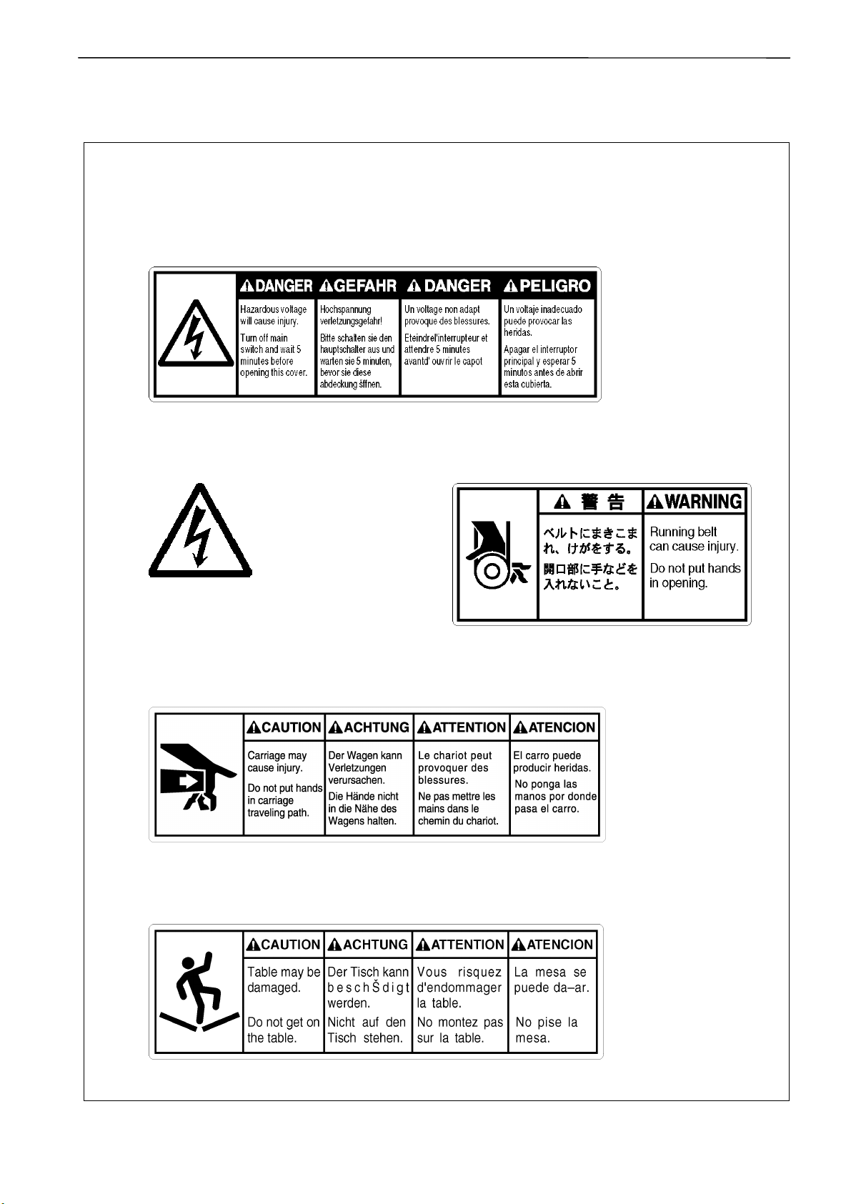
3 Warning labels
* The following warning labels appear on the sewing machine.
Please follow the instructions on the labels at all times when using the machine. If the labels
have been removed or are difficult to read, please contact your nearest Brother dealer.
1 Electric shock danger display
W1408Q
2 Electric shock danger display 3 Injury warning display
Hazardous voltage will
cause injury.
4 Injury caution display
5 Injury caution display
W1410Q
W1200Q
BE-1204B-BC • BE-1204C-BC • BE-1206B-BC 5
W1202Q
Page 8
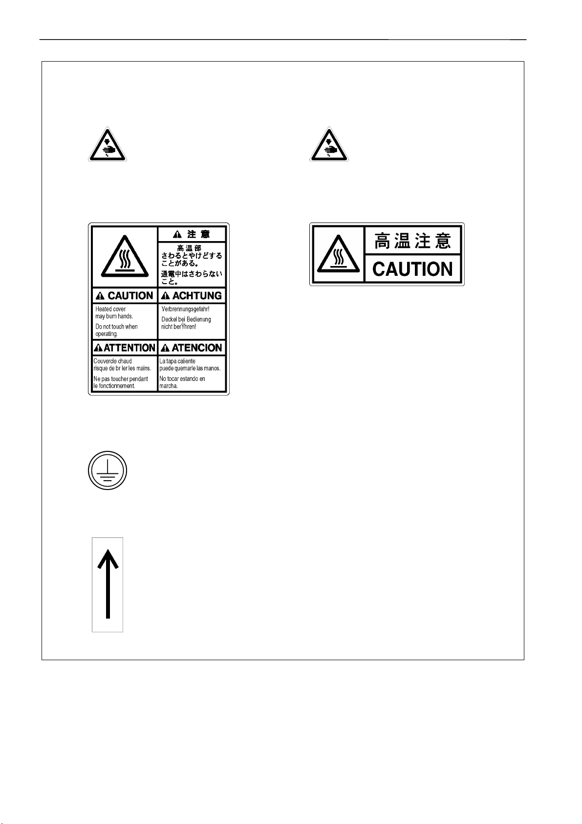
6 Injury caution display
7 Injury caution display
Never touch or push the
thread take up during
operation as it may result in
injuries machine.
Never touch or push the needle
bar during operation as it may
result in injuries or damage to
the sewing machine.
8 High temperature caution display 9 High temperature caution display
W1206Q
Do not touch this part during activitation
or for 30 minutes after shut-off. Otherwise
burns may result.
W1201Q
10 Ground mark
Be sure to connect the ground. If the ground connection is not secure, you run
a high risk of receiving a serious electric shock, and problems with correct
operation may also occur.
11 Direction of operation
W1205Q
6 BE-1204B-BC • BE-1204C-BC • BE-1206B-BC
Page 9
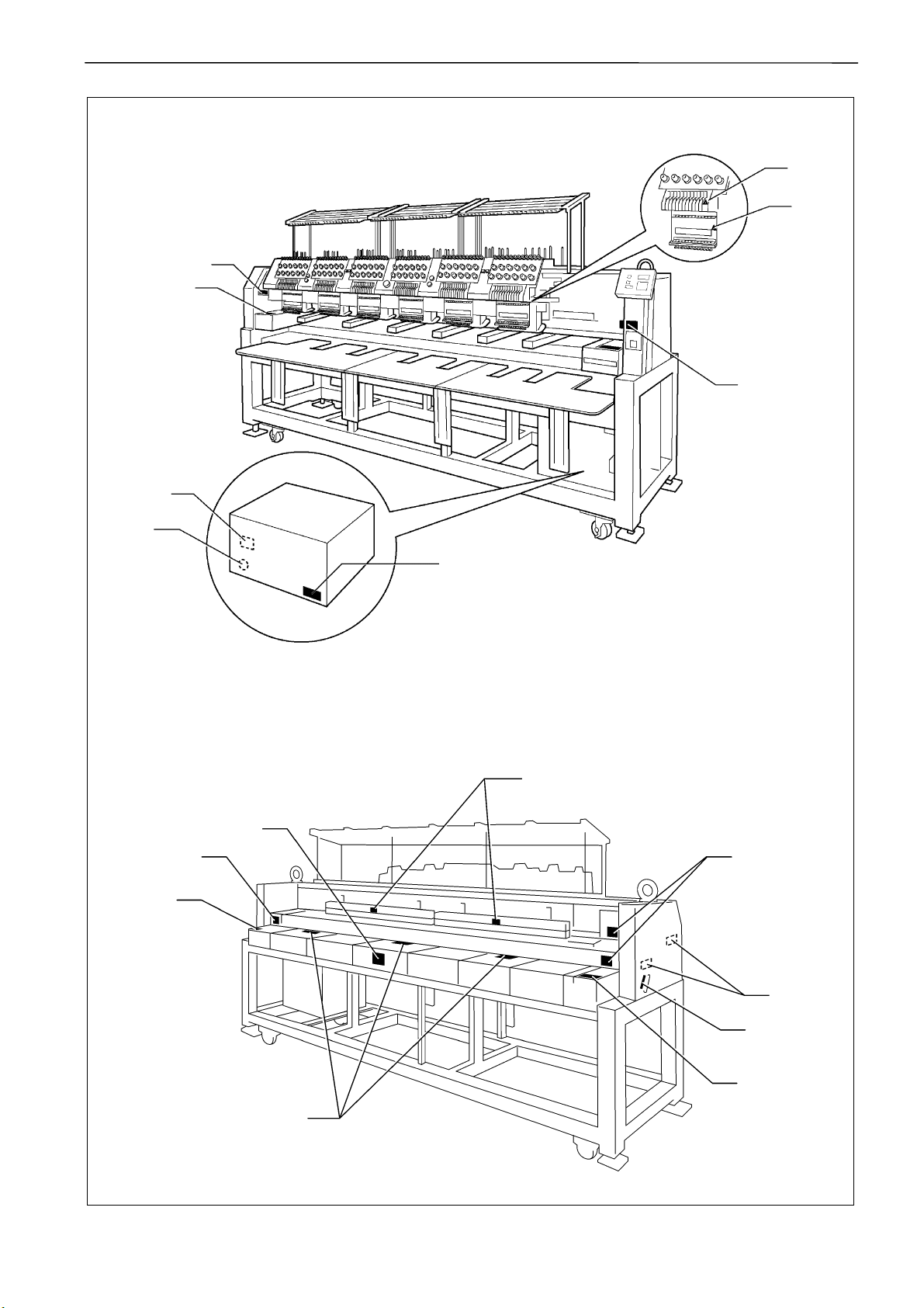
10
6
7
5
4
5
2
1
W1400Q
9
8
8
8
4
3
11
4
4
BE-1204B-BC • BE-1204C-BC • BE-1206B-BC 7
W1208Q
Page 10

Contents
Contents
Chapter 1 Mechanical Descriptions
1. Feed guide mechanism............................................................................................................................................ 1-1
2. Crank shaft mechanism ........................................................................................................................................... 1-2
3. Presser foot mechanism.......................................................................................................................................... 1-3
4. Thread take-up mechanism .....................................................................................................................................1-4
5. Needle bar mechanism ........................................................................................................................................... 1-5
6. Lower shaft and rotary hook mechanisms............................................................................................................. 1-6
7. Thread trimmer mechanism.....................................................................................................................................1-7
8. Thread wiper mechanism ........................................................................................................................................1-8
9. Picker mechanism.................................................................................................................................................... 1-9
10. Needle bar flip-up mechanism.............................................................................................................................1-10
11. Cap frame device.................................................................................................................................................. 1-11
Chapter 2 Parts replacement and adjustment
1. Replacement and adjustment of jump driving assy, cloth presser cam, thread take-up driving cam, needle bar
driving cam, driving belt and upper shaft sensor.................................................................................................. 2-1
2. Replacement and adjustment of thread take-up lever......................................................................................... 2-11
3. Replacement and adjustment of work clamp....................................................................................................... 2-12
4. Replacement and adjustment of stepping motor for thread sweeping and wiper sensor ............................... 2-13
5. Replacement and adjustment of picker solenoid ................................................................................................ 2-16
6. Replacement and adjustment of movable knife and fixed knife.........................................................................2-19
7. Replacement and adjustment of Timing belt, X ...................................................................................................2-21
8. Replacement and adjustment of Timing belt, Y ...................................................................................................2-23
9. Adjusting Needle Bar Height ................................................................................................................................. 2-26
10. Attachment and Adjustment of Rotary Hook......................................................................................................2-30
Chapter 3 Electrical components
1. Location of the PCB .................................................................................................................................................3-1
2. Replacement of PCB inside the control box ..........................................................................................................3-3
2-1. How to detach and attach the control box ........................................................................................................3-3
2-2. Replacement of the main PCB ......................................................................................................................... 3-5
2-3. Replacement of the power supply PCB ............................................................................................................ 3-7
2-4. Replacement of the drive PCB ...................................................................................................................... 3-10
2-5. Replacement of the SBUS PCB (For PC-type model).................................................................................... 3-12
2-6. Replacement of the relay PCB ....................................................................................................................... 3-14
2-7. Replacing the panel PCB (For PC-type model) .............................................................................................. 3-15
2-8. Replacement of the control panel PCB (For SA-type model) ......................................................................... 3-16
3. Replacement of head switch PCB of thread tension base and tension base PCB ........................................... 3-18
4. Replacement of I/O PCB (1, 2) and step back/forward switch PCB....................................................................3-21
5. Replacement of head PCB..................................................................................................................................... 3-23
6. Replacement of I/O PCB.........................................................................................................................................3-25
7. Replacement of picker PCB...................................................................................................................................3-26
8. Fuses ....................................................................................................................................................................... 3-27
8-1. Types and capacity of fuses ........................................................................................................................... 3-28
8-2. Replacement of fuses..................................................................................................................................... 3-28
9. Description of P-ROM ............................................................................................................................................ 3-29
10. Replacement of change color motor, collar, w/dog and change color sensor PCB ....................................... 3-30
11. Replacement and adjustment of index sensor................................................................................................... 3-32
8 BE-1204B-BC • BE-1204C-BC • BE-1206B-BC
Page 11

12. Description of connectors....................................................................................................................................3-35
12-1. Main PCB......................................................................................................................................................3-35
12-2. Drive PCB .....................................................................................................................................................3-42
12-3. Power supply PCB........................................................................................................................................3-47
12-4. IO PCB..........................................................................................................................................................3-53
12-5. Picker PCB....................................................................................................................................................3-57
12-6. Head switch PCB..........................................................................................................................................3-58
12-7. Tension base PCB ........................................................................................................................................3-59
12-8. Step switch PCB ...........................................................................................................................................3-60
12-9. Head PCB.....................................................................................................................................................3-61
12-10. Relay PCB ..................................................................................................................................................3-64
12-11. SBUS PCB ..................................................................................................................................................3-66
Chapter 4 Test Mode (For Stand – Alone type)
1. Entering into the test mode......................................................................................................................................4-1
2. Selecting the test mode menu .................................................................................................................................4-1
3. Function of the test mode ........................................................................................................................................4-3
3-1. Thread trimmer adjustment...............................................................................................................................4-3
3-2. Needle bar moving test ....................................................................................................................................4-3
3-3. Carriage sensor test (Fine adjustment of the carriage origin point) ..................................................................4-5
3-4. Encoder signal test ...........................................................................................................................................4-6
3-5. LED SW test .....................................................................................................................................................4-7
3-6. Port/voltage check ............................................................................................................................................4-8
3-7. Solenoid test .....................................................................................................................................................4-9
3-8. Main shaft motor rotation test..........................................................................................................................4-10
3-9. Detailed version of CPU in the machine .........................................................................................................4-11
3-10. Power supply voltage adjustment .................................................................................................................4-12
3-11. Modifications of X-direction slowing area of a cap frame and its reduction ratio ...........................................4-14
3-12. Modification of the stitch compensation value on the sewing machine .........................................................4-15
Contents
Chapter 5 Test mode (For PC Control type)
1.Test mode on the operation panel ............................................................................................................................5-1
1-1. Starting test mode.............................................................................................................................................5-1
1-2. Selecting test mode menu ................................................................................................................................5-1
1-3. Test mode functions..........................................................................................................................................5-2
2. Test mode and each function on the PC.................................................................................................................5-9
2-1. PC test mode ....................................................................................................................................................5-9
2-2. Confirming the program version......................................................................................................................5-10
2-3. Power supply voltage adjustment ...................................................................................................................5-14
2-4. Modifications of X-direction slowing area of a cap frame and its reduction ratio.............................................5-16
2-5. Modification of the stitch compensation value on the sewing machine ...........................................................5-18
Chapter 6 6. Upgrading version of machine program ...............................................................6-1
Chapter 7 Maintenance
1. Cleaning.....................................................................................................................................................................7-1
1-1. Cleaning and Lubrication of Rotary Hook .........................................................................................................7-1
1-2. Cleaning of Needle Plate ..................................................................................................................................7-2
2. Oiling..........................................................................................................................................................................7-3
2-1. Head .................................................................................................................................................................7-3
2-2. Lower shaft .......................................................................................................................................................7-5
3. Greasing ....................................................................................................................................................................7-6
3-1. Cam grooves.....................................................................................................................................................7-6
3-2. Lower gear........................................................................................................................................................7-8
3-3. Driving shaft......................................................................................................................................................7-8
3-4. The needle bar change mechanism and the case guide rail UL .......................................................................7-9
BE-1204B-BC • BE-1204C-BC • BE-1206B-BC 9
Page 12

Contents
Chapter 8 Troubleshooting
1. Mechanical Section .................................................................................................................................................. 8-1
2. Electrical Section......................................................................................................................................................8-2
Chapter 9 Error code list (For Stand Alone)............................................................................... 9-1
Chapter 10 Error code list (For PC Control type) .................................................................... 10-1
Chapter 11 Block Figure............................................................................................................ 11-1
10 BE-1204B-BC • BE-1204C-BC • BE-1206B-BC
Page 13
Chapter 1 Mechanical Descriptions
Chapter 1 Mechanical Descriptions
The mechanisms operate in the order of the numbers given in the illustrations.
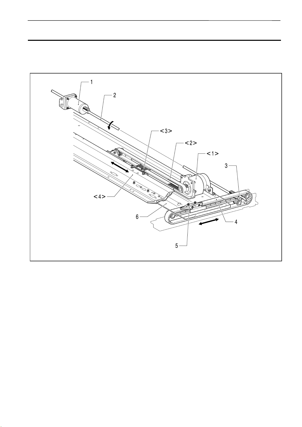
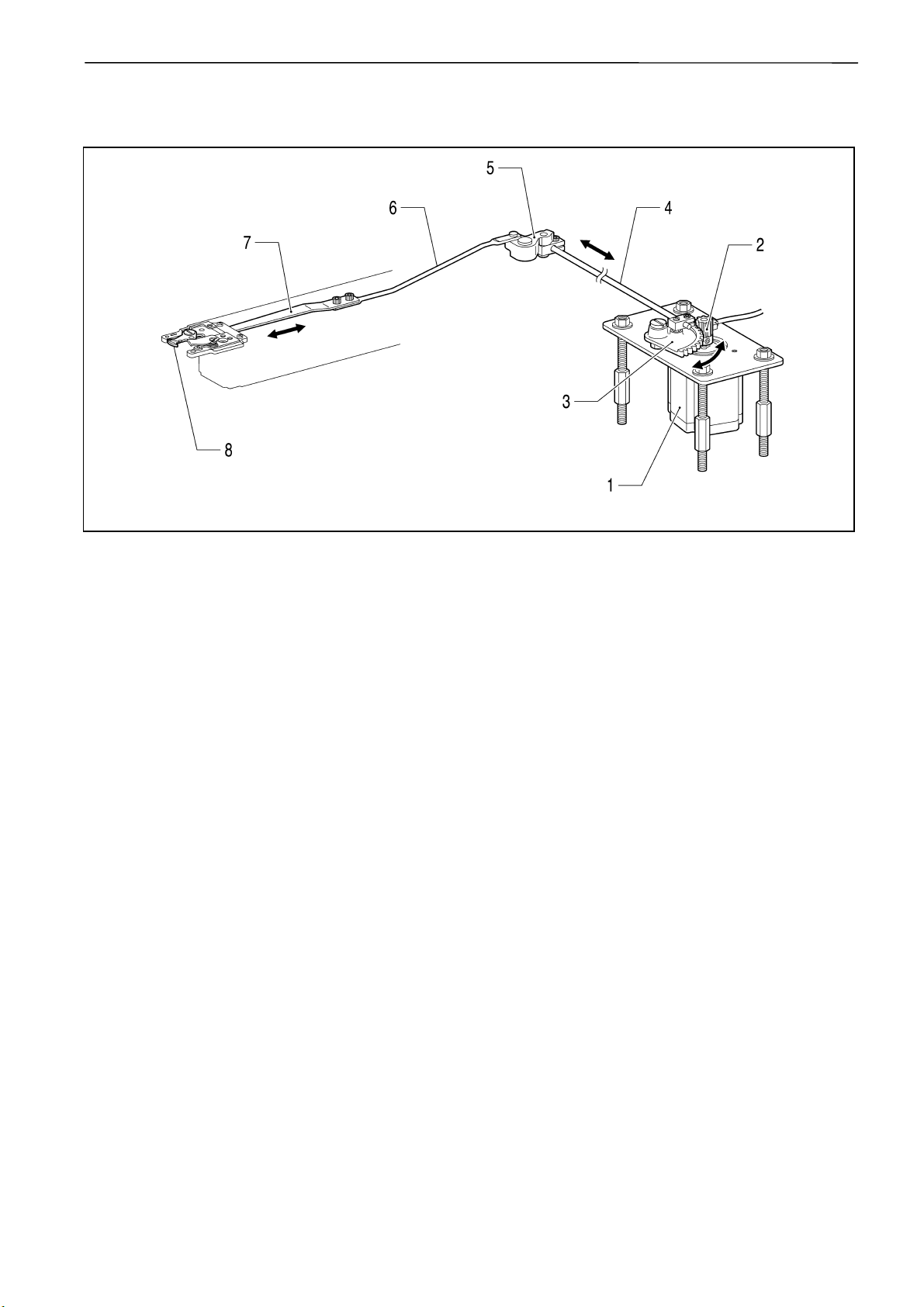
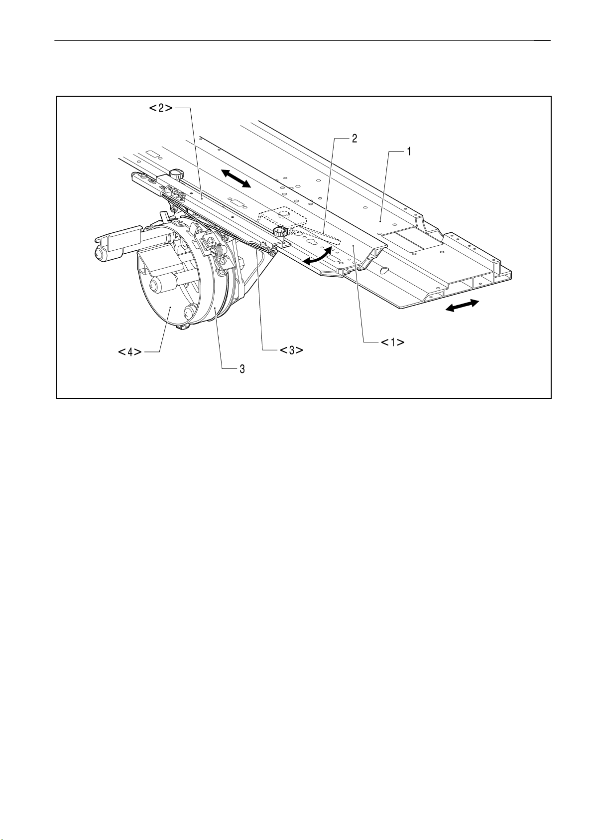
1. Feed guide mechanism
[X direction]
<1>.X-pulse motor
<2>.Timing belt
<3>.X-driving carriage
<4>.X-feed frame
[Y direction]
1.Y-pulse motor
2.Y-driving connecting shaft
3.Y-driving pulley
4.Y-driving belt
5.X-carriage
6.Y-feed frame
2549M
BE-1204B-BC • BE-1204C-BC • BE-1206B-BC 1-1
Page 14
Chapter 1 Mechanical Descriptions
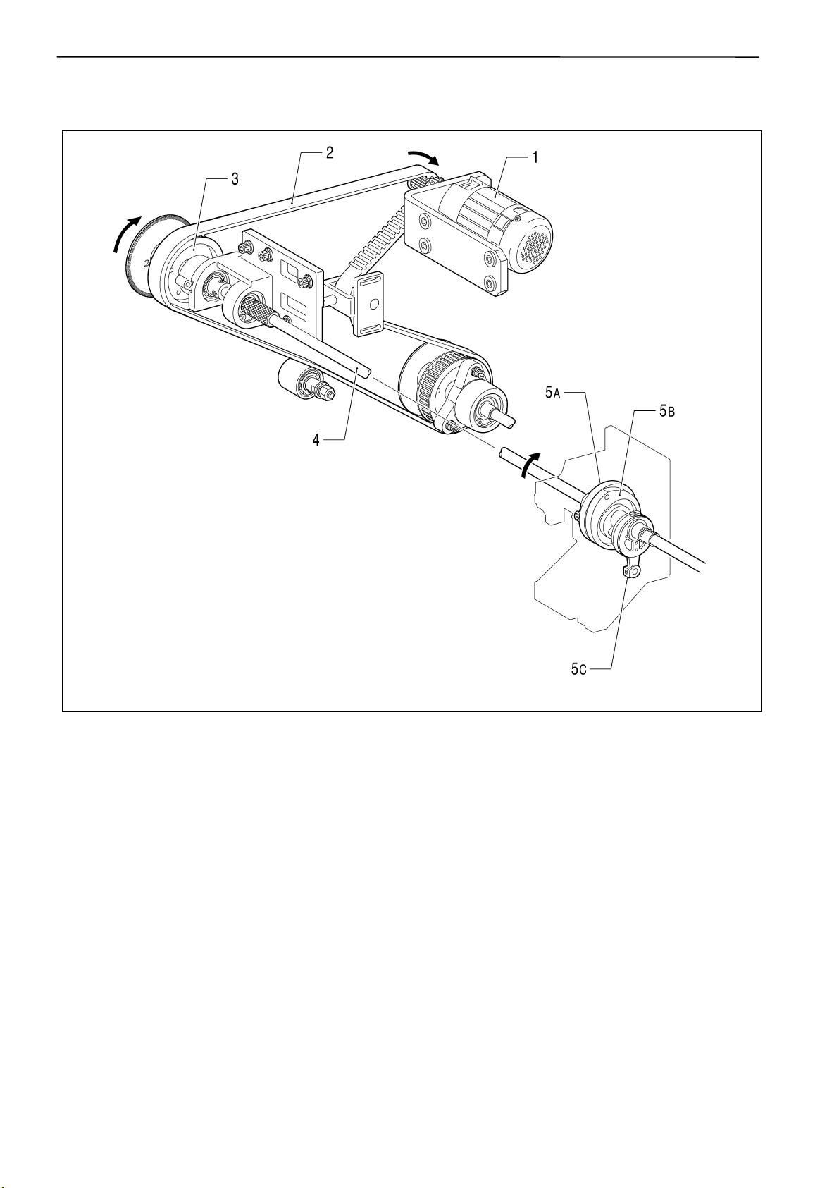
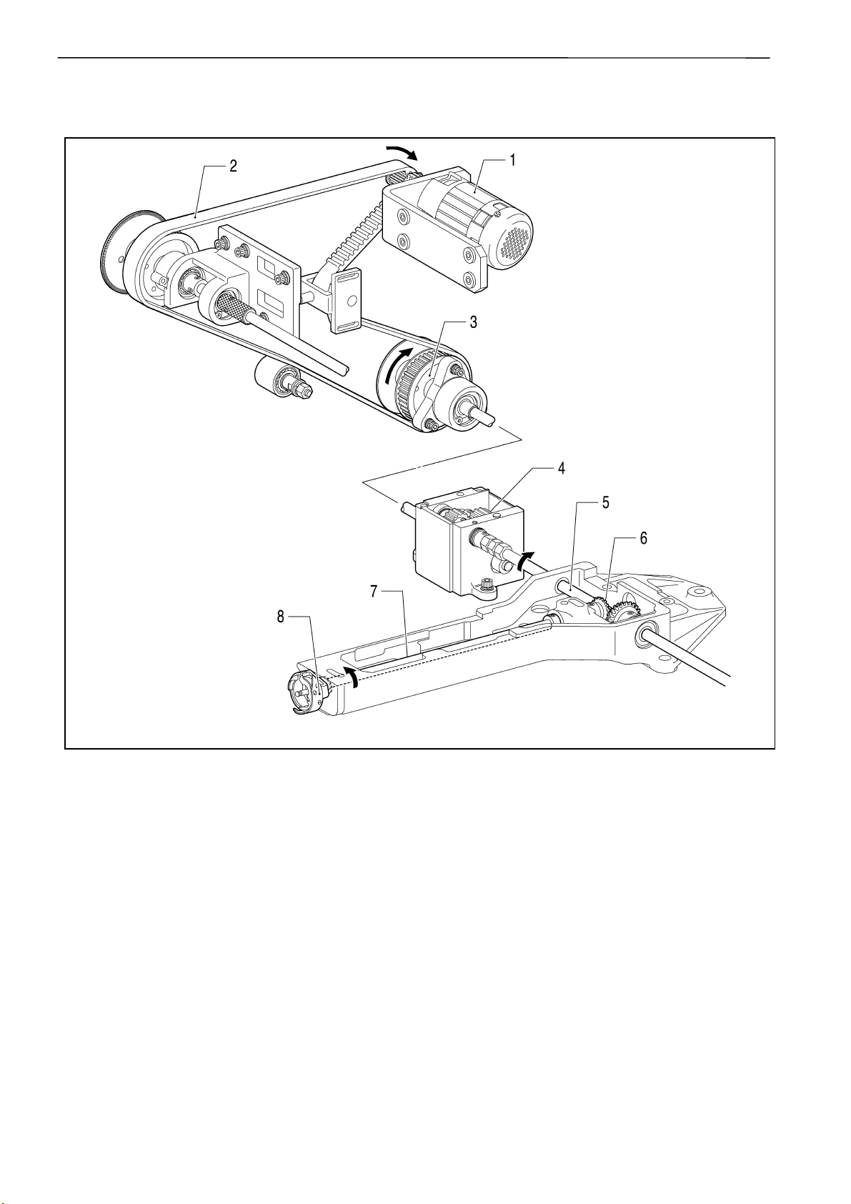
2. Crank shaft mechanism
1.Motor
2.Timing belt
3.Driving pulley
4.Connecting shaft upper
5A.Cloth presser cam
5B.Thread take-up driving cam
5C.Needle bar driving cam
2550M
1-2 BE-1204B-BC • BE-1204C-BC • BE-1206B-BC
Page 15
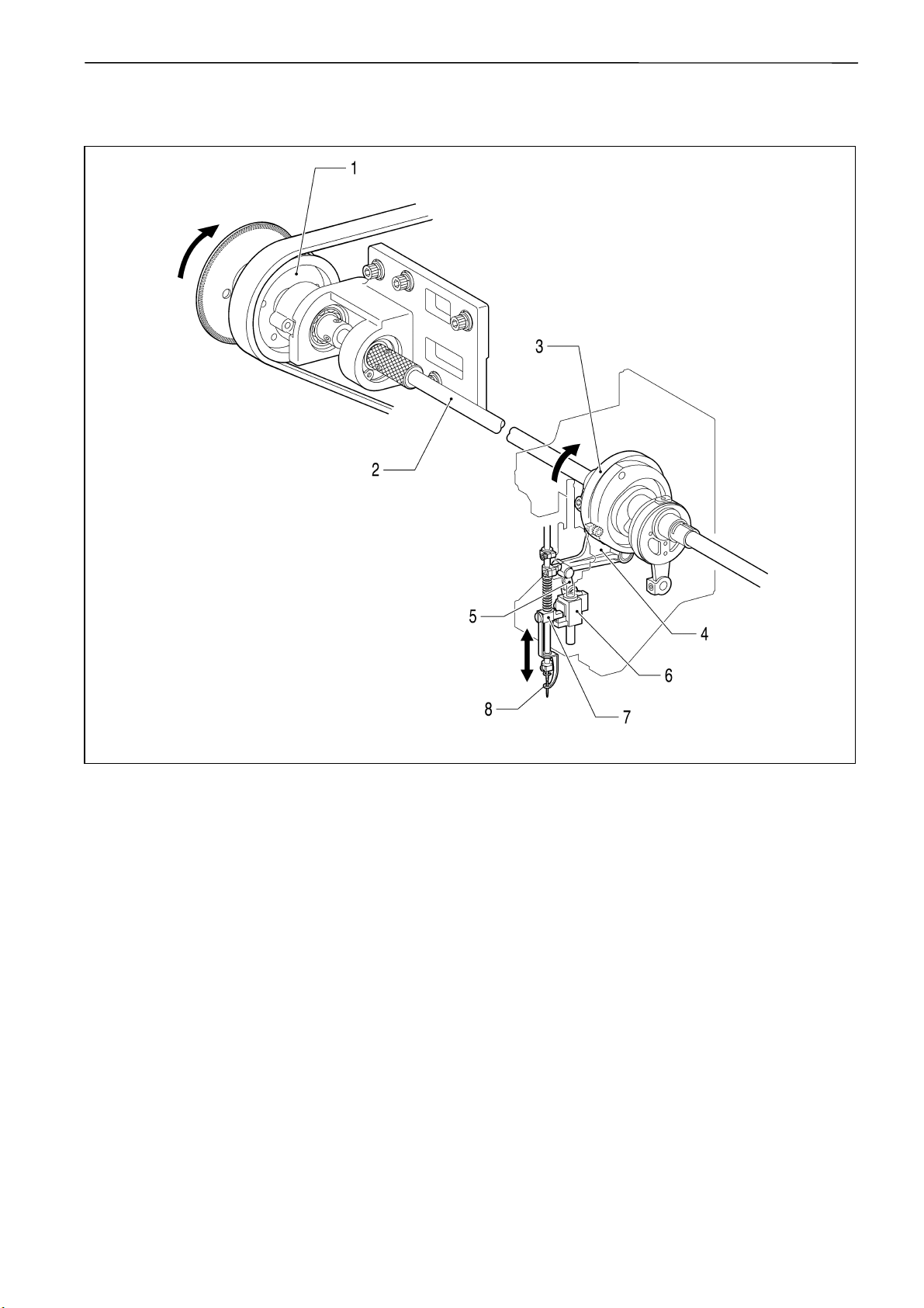
3.Presser foot mechanism
Chapter 1 Mechanical Descriptions
1.Driving pulley
2.Connecting shaft upper
3.Presser foot cam
4.Work clamp driving lever assy
5.Driving connector
6.W-clamp lifting parts
7.Work clamp bracket
8.Presser foot
2551M
BE-1204B-BC • BE-1204C-BC • BE-1206B-BC 1-3
Page 16
Chapter 1 Mechanical Descriptions
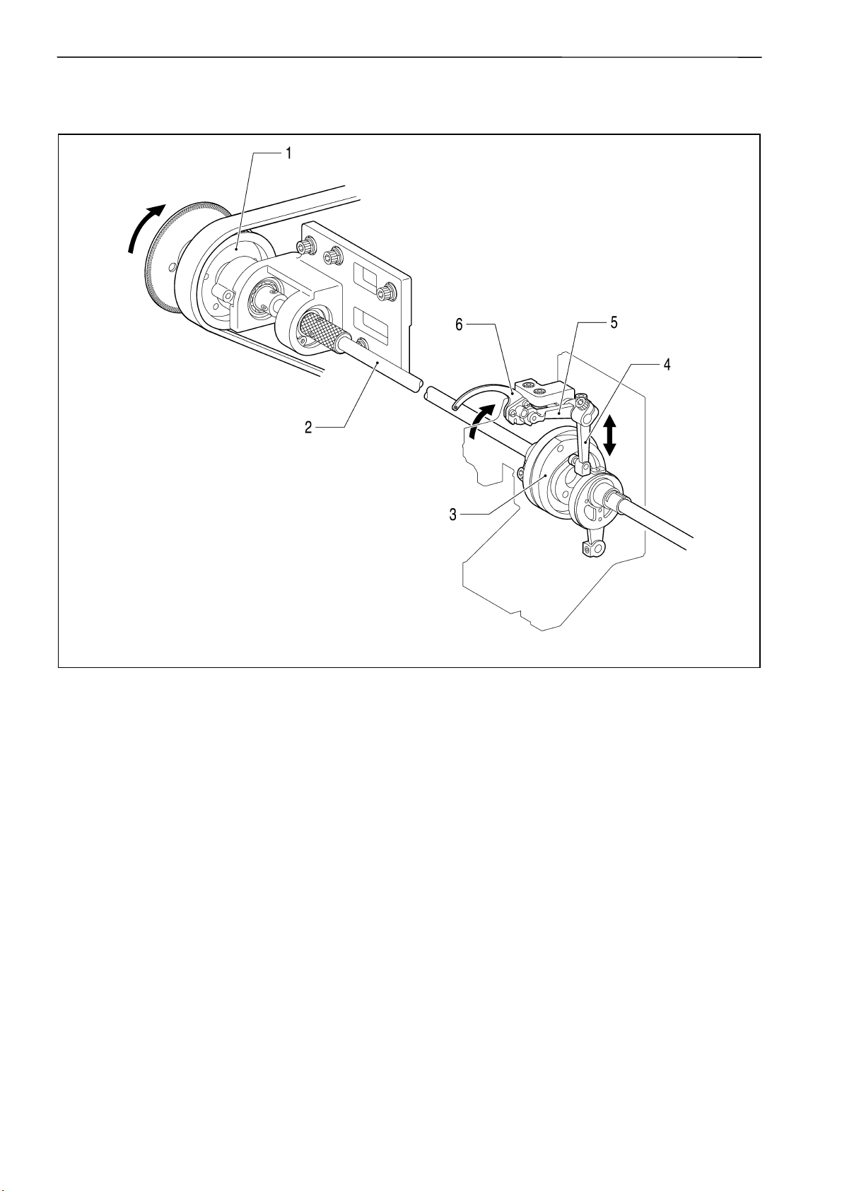
4.Thread take-up mechanism
1.Driving pulley
2.Connecting shaft upper
3.Thread take-up driving cam
4.Thread take-up driving lever
5.Lever
6.Thread take-up lever
2552M
1-4 BE-1204B-BC • BE-1204C-BC • BE-1206B-BC
Page 17
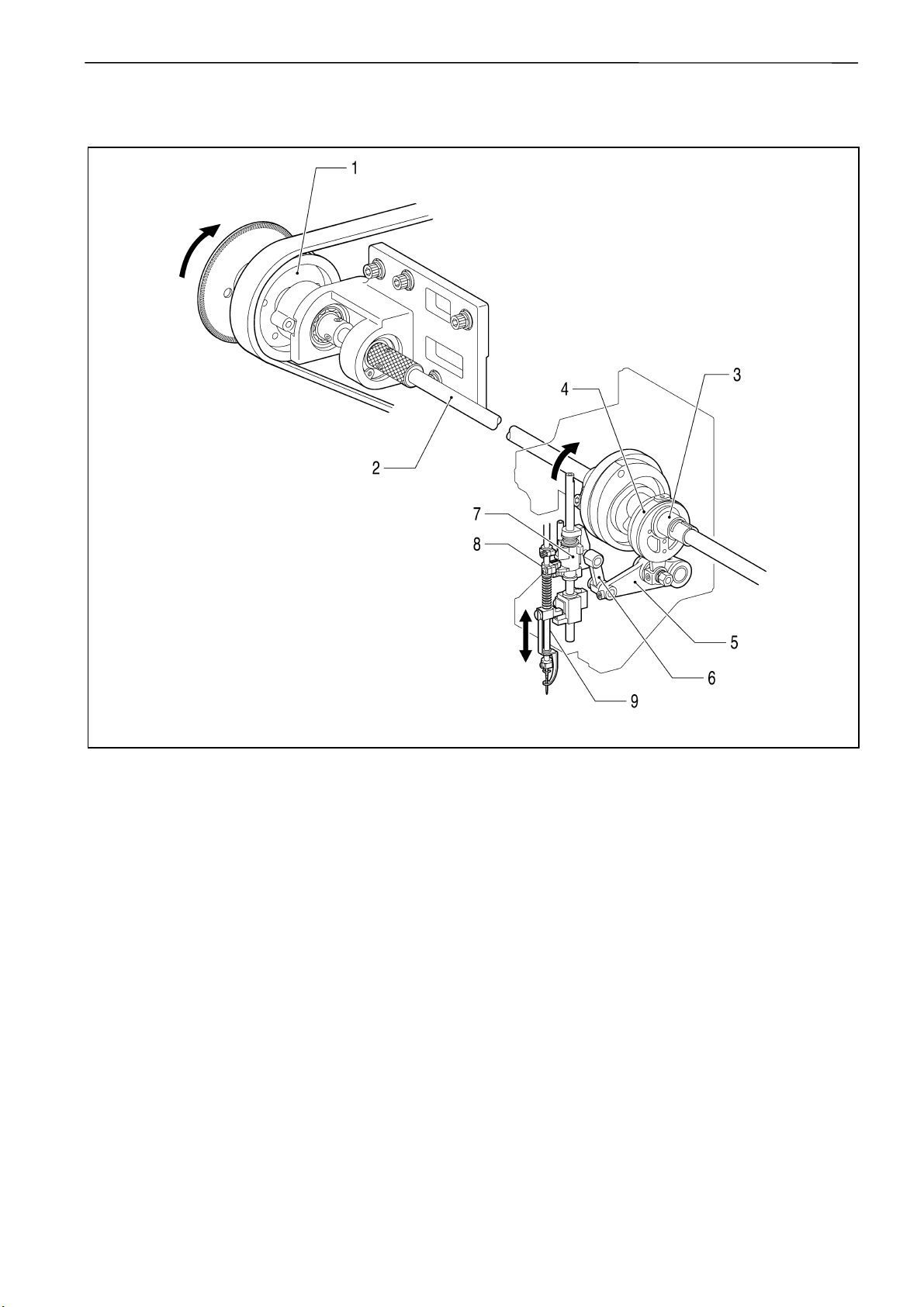
5. Needle bar mechanism
Chapter 1 Mechanical Descriptions
1.Driving pulley
2.Connecting shaft upper
3.Needle bar driving cam
4.Connecting rod
5.Needle bar driving lever
6.Driving connector
7.Needle bar lifting parts
8.Needle bar clamp
9.Needle bar
2553M
BE-1204B-BC • BE-1204C-BC • BE-1206B-BC 1-5
Page 18
Chapter 1 Mechanical Descriptions
6.Lower shaft and rotary hook mechanisms
1.Motor
2.Timing belt
3.Driving pulley
4.Gear
5.Driving shaft lower
6.Lower shaft gear
7.Lower shaft
8.Rotary hook
2554M
1-6 BE-1204B-BC • BE-1204C-BC • BE-1206B-BC
Page 19
7.Thread trimmer mechanism
Chapter 1 Mechanical Descriptions
1.Thread trimmer motor
2.Thread trimmer gear
3.Driving lever
4.Connedtion shaft
5.T-trimmer connecting rod lever
6.T-trimmer connecting rod, B
7.T-trimmer con. rod assy, A
8.Movable knife
2555M
BE-1204B-BC • BE-1204C-BC • BE-1206B-BC 1-7
Page 20
Chapter 1 Mechanical Descriptions
8.Thread wiper mechanism
1.Wiper motor bracket
2.Wiper lever
3.Upper thread hook
2556M
1-8 BE-1204B-BC • BE-1204C-BC • BE-1206B-BC
Page 21
9.Picker mechanism
Chapter 1 Mechanical Descriptions
1.Picker solenoid
2.Picker lever
3.Picker base
4.Picker
2557M
BE-1204B-BC • BE-1204C-BC • BE-1206B-BC 1-9
Page 22

Chapter 1 Mechanical Descriptions
10.Needle bar flip-up mechanism
1.Change color motor
2.Change color gear
3.Shaft
4.Change cam
5.Change roller base
6.Needle bar case
7.Change bracket collar
8.Connection shaft
*A Change color sensor
*B Dog
2558M
1-10 BE-1204B-BC • BE-1204C-BC • BE-1206B-BC
Page 23
11.Cap frame device
Chapter 1 Mechanical Descriptions
[X direction]
<1>.X-feed frame
<2>.Cap frame
<3>.Wire
<4>.Driving ring
[Y direction]
1.Y-feed frame
2.Fixing lever
3.Driving ring
2559M
BE-1204B-BC • BE-1204C-BC • BE-1206B-BC 1-11
Page 24
Chapter 2 Parts replacement and adjustment
Chapter 2 Parts replacement and adjustment
1. Replacement and adjustment of jump driving assy, cloth presser cam,
thread take-up driving cam, needle bar driving cam, driving belt and
upper shaft sensor
[Removing procedure]
2560M
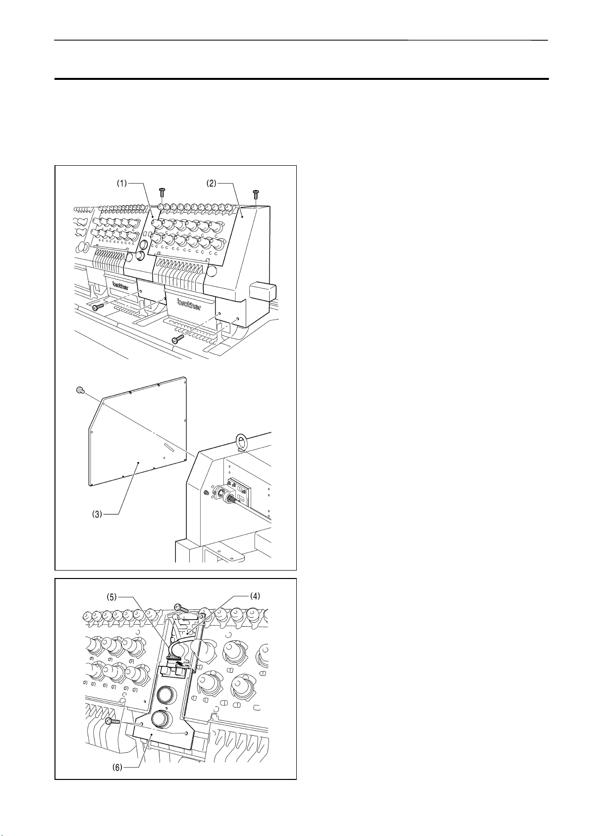
1. Unscrew the screws of cover lower and
upper (1) and cover R (2) to remove them.
Unscrew the screws of side cover L (3) to
remove it.
Also remove the other covers.
2561M
2. Detach the connector of tension base
harness (5) from I/O PCB (4).
Unscrew the screws of base (6) to remove it.
2562M
2-1 BE-1204B-BC • BE-1204C-BC • BE-1206B-BC
Page 25
2563M
Chapter 2 Parts replacement and adjustment
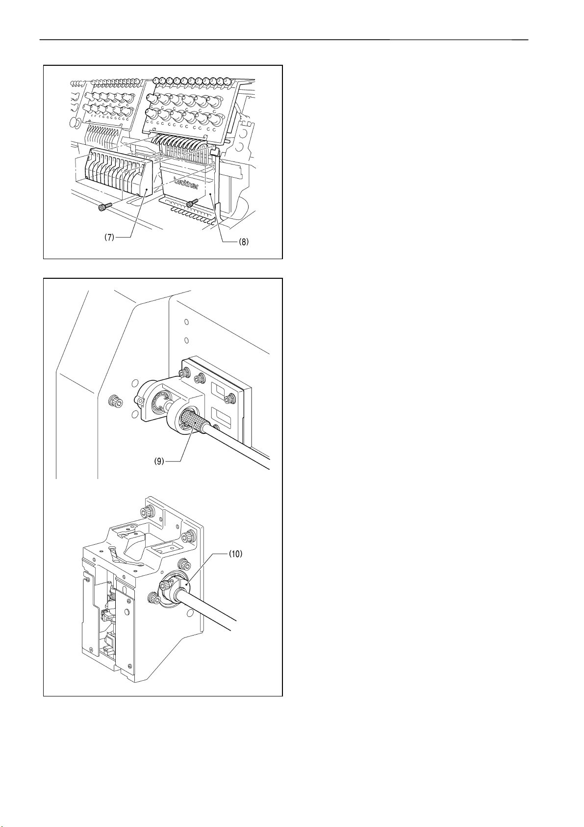
3. Take off 4 bolts of thread take-up cover (7) to
remove it.
4. Take off 4 bolts of needle bar case (8) to
remove it.
2564M
5. Loosen 2 bolts of bearing collar pulley (9),
and also loosen 1 bolt of needle bar cam
collar (10) of each head.
2565M
BE-1204B-BC • BE-1204C-BC • BE-1206B-BC 2-2
Page 26
Chapter 2 Parts replacement and adjustment
2566M
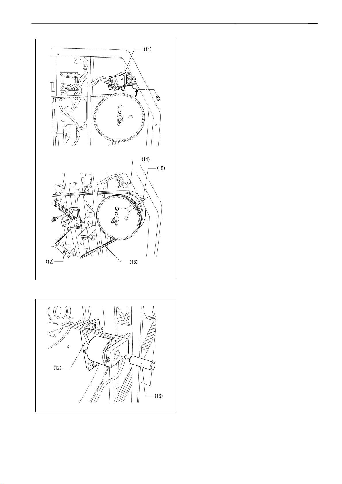
6. Unscrew 1of 2 screws of upper shaft sensor
base plate (11), and then loosen the other
one to fasten upper shaft sensor base plate
(11) upward temporary.
Take off 3 bolts of tensor pulley holder (12)
to remove it.
Detach driving belt (13) from driving pulley
(14).
Extract driving shaft upper (15) together with
driving pulley (14).
2567M
2568M
7. To replace driving belt, loosen 2 set screws
of tension pulley holder (12) to extract
tension shaft (16), and then detach driving
belt (13).
2-3 BE-1204B-BC • BE-1204C-BC • BE-1206B-BC
Page 27
2569M
Chapter 2 Parts replacement and adjustment
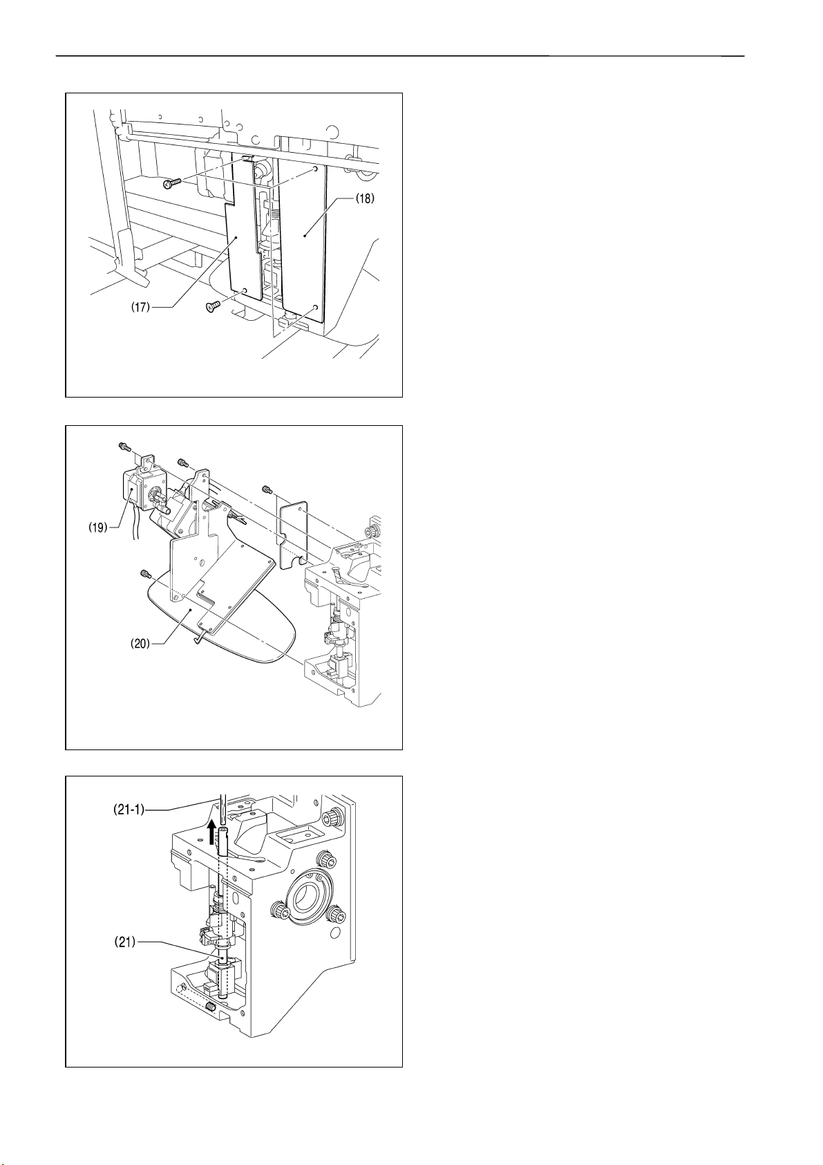
8. Unscrew 2 screws each of front cover R (17)
and front cover L (18) to remove both of
them.
9. Take off 2 bolts of jump driving assy (19) to
remove it.
Take off 2 bolts of wiper driving assy (20) to
remove it.
2570M
10. Remove the base needle bar felt (21-1) and
loosen a set screw, socket to pull out the
base needle bar (21).
2571M
BE-1204B-BC • BE-1204C-BC • BE-1206B-BC 2-4
Page 28
Chapter 2 Parts replacement and adjustment
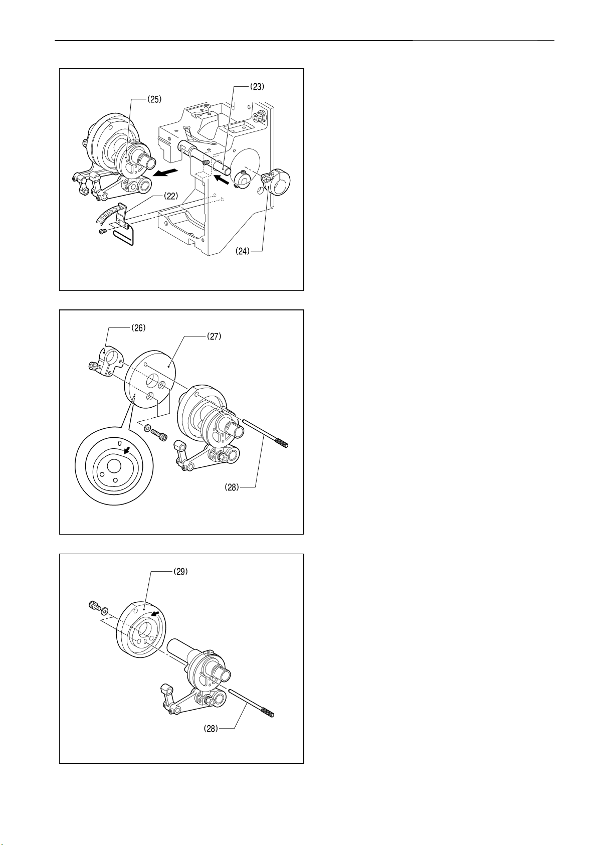
11. Unscrew 2 screws of oil support A (22) to
remove it.
Loosen 3 set screws of driving lever shaft
(23) to extract it.
Loosen 1 bolt of needle bar cam collar (24)
to remove it.
Now needle bar cam (25) can be detached.
2572M
12. Loosen 1 bolt of cloth presser cam collar
(26) to remove it.
Loosen 2 bolts of cloth presser cam (27) to
remove it.
To mount cloth presser cam collar (26),
insert positioning gauge pin (28) into the
positioning hole on the cam and fasten 1
bolt.
Grease the groove of cloth presser cam (27)
indicated by the arrow in the drawing.
2573M
CAUTION
Use the positioning gauge pin included in
the attachment of the sawing machine.
Use the attached grease tank EM-30L for
the greasing.
13. Take off 2 bolts of thread take-up driving cam
(29) to remove it.
To mount thread take-up driving cam (29),
insert positioning gauge pin (28) into the
positioning hole on the cam and fasten 2
bolts.
Grease the groove of thread take-up driving
cam (29) indicated by the arrow in the
drawing.
CAUTION
Use the positioning gauge pin included in
the attachment of the sawing machine.
Use the attached grease tank EM-30L for
the greasing.
2574M
2-5 BE-1204B-BC • BE-1204C-BC • BE-1206B-BC
Page 29
2575M
Chapter 2 Parts replacement and adjustment
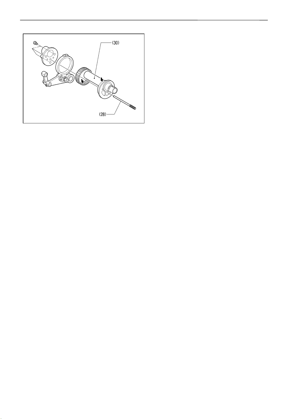
14. Unscrew 2 screws of needle bar driving cam
(30) to remove it.
Grease needle bar driving cam (30) at the
position indicated by the arrow in the
drawing.
To mount needle bar driving cam (30), insert
positioning gauge pin (28) into the
positioning hole on the cam and fasten 2
screws.
CAUTION
Use the positioning gauge pin included in
the attachment of the sawing machine.
Use the attached grease tank EM-30L for
the greasing.
BE-1204B-BC • BE-1204C-BC • BE-1206B-BC 2-6
Page 30
Chapter 2 Parts replacement and adjustment
[Mounting procedure]
To mount pieces, follow the reverse procedure to the disassembly. The followings are the key points in
the mounting.
2576M
LIQUID GASKET
LIQUID GASKET
2577M
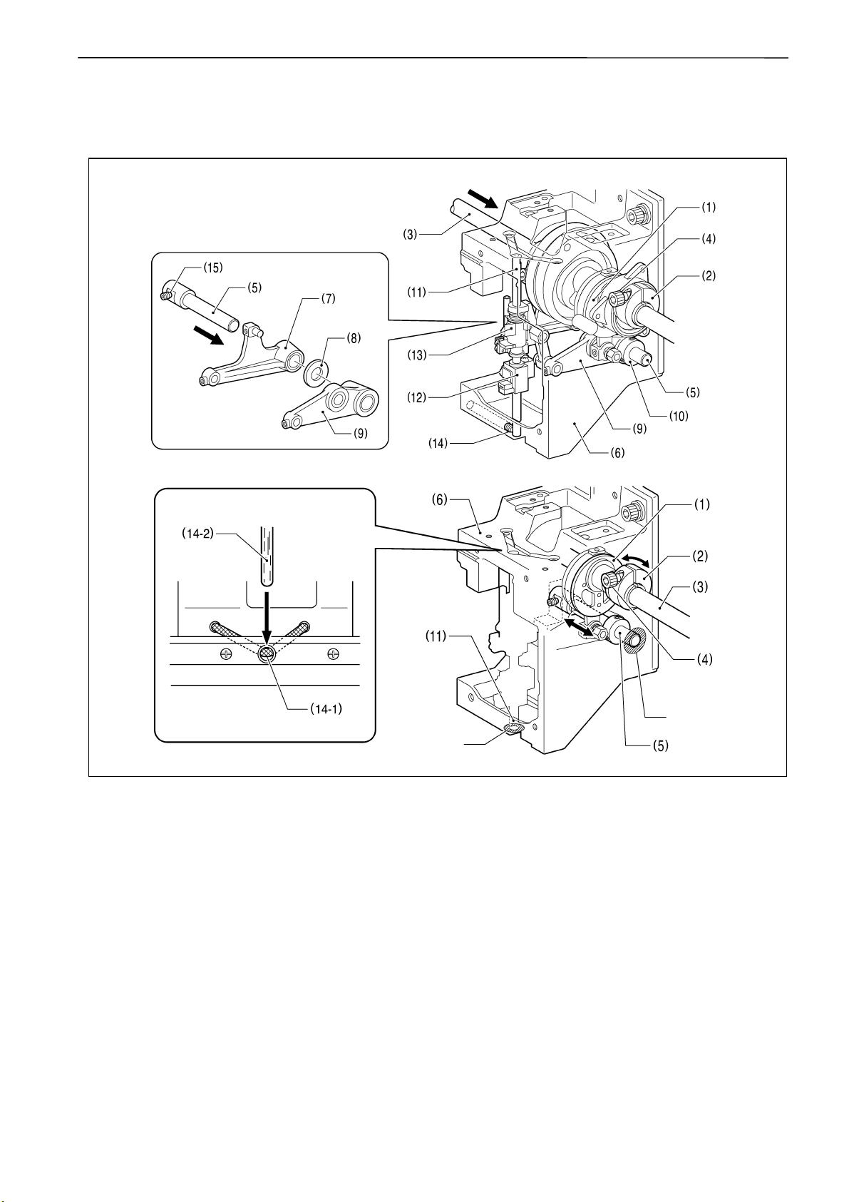
1. Grease the connecting shaft upper on spots that touches bearings of the driving pulley, driving
shaft support or each head.
2. Attach needle bar cam collar (2) to needle bar driving cam (1), insert driving shaft upper (3) and
fasten the bolt (4) temporary so that needle bar driving cam (1) rotates easily.
3. Insert driving lever shaft (5) into head (6), work clamp driving lever (7), spacer (8), needle bar
driving lever (9) and set screw collar (10), then fasten 3 set screws.
4. Spread a sealing agent on the left side of head (6) and lever shaft (5) to prevent oil leak.
5. Insert base needle bar (11) into head (6), work clamp lifting parts (12), and needle bar lifting parts
(13), and fasten 1 set screw (14).
6. Reset the wick (14-1) so that it touches the base needle bar felt (14-2).
7. Spread a sealing agent on the bottom faces of head (6) and base needle bar (11) to prevent oil
leak.
CAUTION
Rotate needle bar cam collar (2) and see if needle bar driving cam (1) rotates easily. If not, loosen
1 set screw (15) of driving lever shaft (5) to shift it toward the thrust for adjustment.
2-7 BE-1204B-BC • BE-1204C-BC • BE-1206B-BC
Page 31

CAUTION
Use three bond 1215 commercially available for the sealing.
Use the attached grease tank EM-30L for the greasing.
Chapter 2 Parts replacement and adjustment
2579M
9. Align driving pulley (16) and the positioning hole on pulley case upper (17), then insert positioning
bar (18) therein.
CAUTION
Use the positioning bar (18) included in the attachment of the sawing machine.
10. Repeat the following procedure for each
head in order: Align the hole on the right side
of the head and the positioning hole of
thread take-up driving cam (19) (needle bar
bottom dead center), then insert positioning
gauge pin (20) therein. Also align slit of
needle bar driving cam (1) and needle bar
cam collar (2), and fasten bolt (4) to fix them.
CAUTION
Use the positioning gauge pin included in
the attachment of the sawing machine.
11. Adjust arrow plate (21) and scale plate (22)
to make 180 degrees angle each other, then
attach driving belt (23) on them.
2578M
BE-1204B-BC • BE-1204C-BC • BE-1206B-BC 2-8
Page 32

Chapter 2 Parts replacement and adjustment
15N
8mm
12. Temporarily fasten 2 bolts (25) which are
fixing tension pulley holder (24).
13. Turn tension adjusting bolt (26) for the
adjustment.
Clockwise turn: Increases the tension
Anticlockwise turn:Decreases the tension
14. Fasten 2 bolts (25) of tension pulley holder
(24), then adjust the holder so that the
bending should be about 8 mm when
pushed with the force of 15 N at the center of
the belt.
Measuring with the sonic tension meter
by Gates Unitta Asia Company,
Unit weight :4.0g/mm
Width :20mm
Span :310mm
Adjust the tension to be 130 N ± 10 N
when (A) is twanged. Be sure to clear
around the belt so that nothing touches it
when twanged.
2580M
2580M
15. Fasten 2 screws (28) of upper shaft sensor
base plate (27) temporarily.
Put sensor position plate (29) as shown in
the illustration, adjusting its position so as to
touch both phase-A sensor (30) and phaseB sensor (39) lightly, and then fasten the 2
screws (28) of upper shaft sensor base plate
(27) firmly.
CAUTION
Use the sensor positioning plate (29)
included in the attachment of the sewing
machine.
2581M
2-9 BE-1204B-BC • BE-1204C-BC • BE-1206B-BC
Page 33

2582M
Chapter 2 Parts replacement and adjustment
16. Insert bed frame side packing (32) between
heads (33), then attach wiper driving assy
(31) with 2 bolts.
No need to adjust any parts in this case.
If troubled, follow the description on Page
2-13. “Replacement and adjustment of
stepping motor for thread sweeping and
wiper sensor”.
2583M
17. Fasten 2 bolts to fix jump driving assy (34) at
the position where jump lever (35) and jump
base (36) make no spaces between them.
18. Spread a sealing agent around the contact
points between the head and the bottom
faces of front cover R (30) and front cover L
(31) to prevent oil leak, then attach those
covers with 2 screws each.
CAUTION
Use three bond 1215 commercially
available for the sealing.
LIQID
GASKET
2584M
BE-1204B-BC • BE-1204C-BC • BE-1206B-BC 2-10
Page 34

Chapter 2 Parts replacement and adjustment
2. Replacement and adjustment of thread take-up lever
2620M
1. Detach needle bar case (1).
Refer to “1. Replacement and adjustment
of jump driving assy, cloth presser cam,
thread take-up driving cam, needle bar
driving cam, driving belt and upper shaft
sensor” for information on how to detach
needle bar case (1).
2. Loosen the right and left set screws, (2) to
pull out thread take-up shaft (3), then detach
thread take-up lever (4).
To mount pieces after the replacement,
follow the reverse procedure to the above.
(Instructions for the mounting)
1. Put the slit of thread take-up position bush
(5) upward and make the faces of needle bar
case stick together on visor before fastening
set screws.
2. Put the slit of thread take-up adjusting bush
(6) upward as well and keep the clearance
between thread take-up adjusting bush (6)
and thread take-up lever (4) to be within 0.3
to 0.5 mm before fixing them.
Slit
2621M
Turn driving pulley and follow the procedure below to adjust the heights of the other thread take-up
lever (4) and lever (7) to be even when driving pulley is angled at 100 degrees (stop position).
Loosen bolt, socket (8) which is fixing lever (7) to
adjust the height of thread take-up lever (4) when
driving pulley is angled at 100 degrees (stop
position).
CAUTION
Adjust the position not to make a noise
“Click” when changing the color.
2622M
2-11 BE-1204B-BC • BE-1204C-BC • BE-1206B-BC
Page 35

3. Replacement and adjustment of work clamp
1. Unscrew 2 screws of lower cover (1) to
detach it.
2. Unscrew 2 screws of lower thread eyelet (2)
to detach it.
2623M
Chapter 2 Parts replacement and adjustment
2624M
3. Unscrew needle clamp screw (3) to detach
needle (4), needle bar thread guide (5) and
work clamp cushion (6).
4. Unscrew screw, M3 (7) to detach work clamp
(8).
To mount pieces after the replacement,
follow the reverse procedure to the above.
How to adjust the height of work clamp (8)
1. Loosen screw, M3 (7) to adjust the height of
work clamp (8) so that the bottom face of
cloth presser and the upper surface of the
cloth touch each other at the alignment point
of the N.H mark (200 degrees) and the arrow
plate (contact point between the needle and
rotary hook).
Cloth
2625M
BE-1204B-BC • BE-1204C-BC • BE-1206B-BC 2-12
Page 36

Chapter 2 Parts replacement and adjustment
4.Replacement and adjustment of stepping motor for thread sweeping and
wiper sensor
Turn off the power of the sewing machine.
[How to detach]
2626M
1. Detach bolt (1) and then detach cord holder
washer (2).
2. Detach wiper sensor connector P2 or P3 (4)
from head PCB (3).
3. Unscrew 1 screw (6) of wiper sensor bracket
(5) and replace sensor PCB (7).
4. Detach wiper stepping motor connector P8
or P9 (8) from head PCB (3)
2627M
5. Detach the nut of shoulder screw (11) to
detach upper thread hook (10) from wiper
lever (9).
6. Detach 2 bolts (14) to detach wiper motor
bracket (13) from wiper assy reference base
(12), then replace stepping motor (15).
2628M
2-13 BE-1204B-BC • BE-1204C-BC • BE-1206B-BC
Page 37

Chapter 2 Parts replacement and adjustment
[How to mount]
To mount pieces, follow the reverse procedure to the disassembly.Key points in the mounting and the
adjustment afterward are described below.
2629M
1. Mount wiper lever (9) and upper thread hook
(10), and then move them with fingers in the
direction of arrow to see if they can be
moved easily. If not, loosen 4 set screws
(16) of thread nipper (15) to adjust the height
until they become lighter. Then check needle
bar No. 1 and No. 12.
2630M
2. Put wiper sensor bracket (5) according to the
arrow direction, adjusting the gap between
the emboss (6) to be 1 mm as shown in the
illustration, and then secure the bracket with
1 screw (6).
2631M
BE-1204B-BC • BE-1204C-BC • BE-1206B-BC 2-14
Page 38

Chapter 2 Parts replacement and adjustment
5. Replacement and adjustment of picker solenoid
[How to detach]
2636M
2637M
2632M
2639M2638M
1. Unscrew screws of table cover (1) and bed cover B (2), and then remove each cover.
2. Disconnect the connector of picker solenoid (3).
3. Unscrew picker shoulder screw (4).
4. Unscrew 2 screws (5) to detach picker setting plate (6), and then replace picker solenoid (7).
2-15 BE-1204B-BC • BE-1204C-BC • BE-1206B-BC
Page 39

Chapter 2 Parts replacement and adjustment
[How to mount]
To mount pieces, follow the reverse procedure to the disassembly. Key points in the mounting and the
adjustment afterward are described below.
2640M
1. Adjust the position of picker setting plate (6)
by moving it back and forth so that the tip of
picker (8) keeps 14.0-14.5 mm distance from
bobbin (9) when picker solenoid (3) is turned
off, and then fasten 2 screws (5) there.
(Cautions in the mounting)
1. Confirm that picker lever (10) does not touch
bed (11).
2641M
BE-1204B-BC • BE-1204C-BC • BE-1206B-BC 2-16
Page 40

Chapter 2 Parts replacement and adjustment
2642M
2. Check if the distance between the tip of
picker (8) and bobbin (9) is whithin 0.5 to 1.0
mm when picker solenoid (3) is turned on. If
it is less, repeat the adjustment of 1. again.
3. Check if the distance between the upper
surface of the tip of picker (8) and the bottom
face of rotary hook sttopper is within 3.5 to
4.5 mm. If the distance is out of range,
loosen 2 screws (12) to adjust the height of
picker (8).
2643M
2-17 BE-1204B-BC • BE-1204C-BC • BE-1206B-BC
Page 41

Chapter 2 Parts replacement and adjustment
6. Replacement and adjustment of movable knife and fixed knife
[How to detach]
2644M
1. Unscrew screws of needle plate (1) and bed
cover B (2), and then remove both.
2. Unscrew screw (4) of fixed knife (3) and
screw (6) of movable knife (5), and then
detach both knives.
2645M
[How to mount]
To mount pieces, follow the reverse procedure to the disassembly. Key points in the mounting and the
adjustment afterward are described below.
1. Attach movable knife (5).
2. Detach 2 bolts (7) of T-trimmer con. rod assy,
A (6).
3. Slide the tip of fixed knife (3) to the left and
fasten 1 screw (4) temporarily.
4. Fasten screw (4) of fixed knife (3) gradually
with shifting movable knife (5).
CAUTION
A quick fastening of screw (4) of fixed knife
(3) might destroy both knives when
operating.
2646M
BE-1204B-BC • BE-1204C-BC • BE-1206B-BC 2-18
Page 42

Chapter 2 Parts replacement and adjustment
5. Put a thread between movable knife (5) and
fixed knife (3) to cut it for testing.
Thread
2647M
2648M
6. If it does not cut well, insert movable knife
spacer (8) in the attachment beneath
movable knife (5) to increase the pressure of
the knife.
7. Fasten 2 bolts (7) of T-trimmer con. rod assy,
A (6) temporarily.
8. Shift to the test mode.
For Stand Alone type : Refer to Chapter 4
For PC Control type : Refer to Chapter 5
9. Pushing step back switch (9) will operate
movable knife (5) indicated by the arrow.
Loosen 2 bolts (7) of T-trimmer con. rod assy,
A (6) for the adjustment so that the tip of
movable knife (5) sticks out by 1 mm from
fixed knife (3) when it is in the side A.
2649M
2-19 BE-1204B-BC • BE-1204C-BC • BE-1206B-BC
Page 43

7. Replacement and adjustment of Timing belt, X
[How to detach]
Chapter 2 Parts replacement and adjustment
2650M
2651M
2652M
1. Turn off the power.
2. Unscrew screws of X-feed cover L, R and C (1) to detach them from Y-frame (2).
3. Loosen 2 bolts (4) fixing X-pulley bracket (3) to loosen bolt, socket (5) to the limit which is for the
belt tension adjusment.
4. Detach 4 bolts of belt stopper plate, 20 (7) attached to X-driving carriage (6), and then detach
timing belt (8) and belt stopper plate, 20 (7) from X-driving carriage (6).
5. Loosen bolts (10), extract pulley shaft (11), and remove timing belt (8).
BE-1204B-BC • BE-1204C-BC • BE-1206B-BC 2-20
Page 44

Chapter 2 Parts replacement and adjustment
[How to mount]
To mount pieces, follow the reverse procedure to the disassembly. Key points in the mounting and the
adjustment afterward are described below.
2654M
1. Slide X-feed frame (10) to the limit to the X
pulse motor side.
2. Loosen 2 bolts (4) fixing X-pulley bracket (3)
and turn bolt (5) to adjust the belt tension.
• Right turn : Increases the tension.
• Left turn : Decreases the tension.
3. Fasten 2 bolts fixing X-pulley bracket (3),
and adjust the deflection under the force of
15 N pressing down at the belt center to be 9
mm.
Measuring with the sonic tension meter
by Gates Unitta Asia Company,
Unit weight : 4.0 g/mm
Width : 20 mm
Span : 653 mm
Adjust the tension to be 200 N ± 10 N
when twanged at the point indicated by
the arrow. Be sure to clear around the belt
so that nothing touches it when twanged.
2655M
4. Follow the procedures below to adjust
sewing machines with double X-pulse
motors.
Loosen 2 bolts (12) of X-feed frames (11)
attached to the right and left X-driving
carriages.
Turn on the power to keep X-pulse motor
excited, and then fasten 4 bolts (12) on X-
feed frame (11) in total on the right and left
sides, adjusting each position to have even
clearances on the both sides of the bolt in
the hole.
CAUTION
If this adjustment has been done improperly,
X feeding might be failed during the sewing.
X feeding failures might be caused also by
2656M
2-21 BE-1204B-BC • BE-1204C-BC • BE-1206B-BC
the improper frame settings for the sewing
machine.
Page 45

8. Replacement and adjustment of Timing belt, Y
[How to detach]
Chapter 2 Parts replacement and adjustment
2650M
1. Turn off the power.
2. Unscrew screws of X-feed cover L, R, C (1)
and X-motor cover to detach them all from
Y-frame (2) .
3. Unscrew screws of Y-feed cover front and
rear (2) to detach them from Y-cover
support.
2657M
2659M
4. Detach 6 bolts (4) in total on the both sides
of Y-feed frame (3) to detach it from Ycarriage (5) on the both sides.
BE-1204B-BC • BE-1204C-BC • BE-1206B-BC 2-22
Page 46

Chapter 2 Parts replacement and adjustment
2658M
2660M
2661M
5. Loosen 2 bolts (5) fixing pulley bracket YF (6) and then loosen bolt (7) to the limit for the belt
tension adjustment.
6. Unscrew 1 bolt, socket (9) and 1 screw, flat (10), and then detach Y-frame support plate (8).
7. Unscrew 4 bolts (12) to detach Y-carriage (11).
8. Detach Y-driving belt (13) from Y pulley A (14) and Y-driving pulley (15) etc.
2-23 BE-1204B-BC • BE-1204C-BC • BE-1206B-BC
Page 47

Chapter 2 Parts replacement and adjustment
[How to mount]
To mount pieces, follow the reverse procedure to the disassembly. Key points in the mounting and the
adjustment afterward are described below.
2662M
1. Slide Y-feed frame (1) to the back from the
front face of the sewing machine to the limit.
2. Loosen 2 bolts (3) fixing pulley bracket, YF
(2) and loosen bolt, socket (4) to the limit for
the belt tension adjustment.
•Right turn : Increases the tension.
•Left turn : Decreases the tension.
3. Fasten 2 bolts (3) fixing pulley bracket, YF
(2), and adjust the deflection under the force
of 15 N pressing down on the belt at the
point of 250 mm from the front timing pulley
to be about 3 mm.
Measuring with the sonic tension meter
by Gates Unitta Asia Company,
Unit weight : 4.0 g/mm
Width : 35 mm
Span : 590 mm
Adjust the tension to be 370 N ±10 N
when twanged at the point indicated by
the arrow. Be sure to clear around the belt
so that nothing touches it when twanged.
2663M
BE-1204B-BC • BE-1204C-BC • BE-1206B-BC 2-24
Page 48

Chapter 2 Parts replacement and adjustment
9. Adjusting Needle Bar Height
W1304Q
(1)
(5)
(4)
(6)
(2)
(3)
11.3 mm
W1306Q
1. Put the attached T-shaped hexagonal
wrench (4 mm) into the hole (1) on the left
side of the machine body, and adjust the
arrow plate to align with 180° (N.D mark) to
move the needle bar to the lowest point.
2. Loosen Needle bar guide bracket set screw
(6) and the bolt (3) of the top dead center
stopper (4) when the needle tip is positioned
11.3 mm above the center of the rotary hook
shaft. Adjust the position of the needle bar
thread guide so that the set screw (2) on it is
turned to the right by 25 - 30°. Tighten
Needle bar guide bracket set screw (6)
securely.
When tightening the needle bar clamp set
screw (6), the hole in the needle bar guide
should face the front.
W1305Q
2-25 BE-1204B-BC • BE-1204C-BC • BE-1206B-BC
Page 49

(5)
Chapter 2 Parts replacement and adjustment
Tighten the
bolt (6) so
that the
clearance
can be even.
(7)
(4)
(6)
W1296Q
Do not hit
this section.
(7)
W1307Q
3. Set the needle bar at the highest position (where the arrow plate and the “N.U.” mark are aligned).
Lightly press the top dead center stopper (4) toward the cushion rubber (5), and tighten Socket
head bolt for top dead center stopper (6) while pressing down the needle bar clamp so that it faces
the front. (Tightening torque: 0.78 N • m)
• Make sure that the top dead center stopper does not hit the needle bar guide rail (7) at
this time.
• When tightening the upper dead point stopper bolt (6), insert the longer side of the
attached wrench into the bolt and tighten it by using the shorter side.
Excessive tightening may make the needle bar movement sluggish.
BE-1204B-BC • BE-1204C-BC • BE-1206B-BC 2-26
Page 50

Chapter 2 Parts replacement and adjustment
■When using the bottom dead center gauge
CAUTION
Use the gauge (S58553001 Bottom dead center gauge) included in the accessories of the sewing
machine for this operation.
1. Put the attached T-shaped hexagonal
wrench (4 mm) into the hole (1) on the left
side of the machine body, and adjust the
arrow plate to align with 180 degrees (N.D
mark) to move the needle bar to the lowest
point.
(1)
W1304Q
Cut
(2)
(3)
W1306Q
Cut
(4)
(7)
(5)
(6)
(8)
(2)
11.3 mm
W1308Q
2. Insert the bottom dead center gauge (2) into the rotary hook (3).
3. Loosen the screw (5) of the needle bar clamp (4) and Socket head bolt for top dead center stopper
(8), then move the needle bar up and down until the needle tip touches the gauge (2) lightly.
• The needle point should touch the gauge at a place other than the cutting section.
• The bottom dead center gauge should be set in or removed from the rotary hook with its
cutting section facing upward.
4. Tighten the screw (5) of the needle bar clamp (4) securely.
2-27 BE-1204B-BC • BE-1204C-BC • BE-1206B-BC
Page 51

(7)
Chapter 2 Parts replacement and adjustment
Tighten the
bolt (8) so
that the
clearance
can be even.
(9)
(6)
(8)
W1296Q
Do not hit
this
section.
(9)
W1307Q
5. Set the needle bar at the highest position (where the arrow plate and the "N.U.”mark are aligned).
Lightly press the top dead center stopper (6) toward the cushion rubber (7), and tighten Socket
head bolt for top dead center stopper (8) while pressing down the needle bar clamp so that it faces
the front. (Tightening torque: 0.78 N • m)
• Make sure that the top dead center stopper (6) does not hit the needle bar guide rail (9) at
this time.
• When tightening the upper dead point stopper bolt (8), insert the longer side of the
attached wrench into the bolt and tighten it by using the shorter side.
Excessive tightening may make the needle bar movement sluggish.
BE-1204B-BC • BE-1204C-BC • BE-1206B-BC 2-28
Page 52

Chapter 2 Parts replacement and adjustment
10. Attachment and Adjustment of Rotary Hook
(3)
(2)
(1)
W1309Q
W1310Q
1. Turn the power switch off.
2. Select the needle bar No. 1 (1).
3. Remove two flat screws (2) and dismount
the needle plate (3).
4. Adjust so that the needle (4) and the point of
rotary hook (5) should meet at the position
(where the arrow plate aligns with N.H mark
(200 û)) higher by 1.7 mm than the needle bar
lowest point (180 û ).
Perform this after the height adjustment
of the needle bar.
W1314Q
0.1 - 0.3 mm
Lower
2845M
2846M
5. Turn the rotary hook manually until the point
of rotary hook (5) turns up.
6. Adjust the clearance between the needle
and the rotary hook to be within 0.1 to 0.3
mm.
Confirm that the height of the needle bar
is 1.8 mm then.
7. Temporarily fasten either one of screws (6).
8. Check with needle bars of No. 2 to No. 12 if
the clearance between each needle and the
rotary hook is within 0.1 to 0.3 mm.
If there are any needles with clearances
out of the range above, adjust them again
to get proper clearances.
W1313Q
9. Fully tighten the screw (6).
2-29 BE-1204B-BC • BE-1204C-BC • BE-1206B-BC
Page 53

Chapter 3 Electrical components
1. Location of the PCB
Chapter 3 Electrical components
PC-type model
(1) Main PCB
(2) D-drive PCB
(3) Power supply PCB
(4) Panel PCB
(5) I/O PCB
(6) Picker PCB
(7) Head switch PCB
(8) Tension base PCB
(9) Thread breakage sensor PCB
(10)Head-head I/O PCB
(11)Step switch PCB
(12)Wiper sensor PCB
(13)Index sensor A, B, C, D
(14)Index sensor PCB
(15)SBUS PCB (PC –type model)
2585M
BE-1204B-BC • BE-1204C-BC • BE-1206B-BC 3-1
Page 54

Chapter 3 Electrical components
(16)Head PCB
(17)Y-feed sensor
(18)X-feed sensor
(19)Thread breakage sensor PCB
(20)Encoder sensor A, B
(21)Needle stop position sensor
2586M
3-2 BE-1204B-BC • BE-1204C-BC • BE-1206B-BC
Page 55

Chapter 3 Electrical components
DANGER
Before opening the cover of control box, be sure to turn off the main power switch, pull out the plug and wait for
5 minutes at least.
Touching the high voltage parts might cause serious injuries.
2.Replacement of PCB inside the control box
2-1.How to detach and attach the control box
1. Loosen 5 screws and unscrew remaining 5
screws on the right side cover of the sewing
machine, and then remove the side cover
(1).
2587M
2588M
2. Pull out all connectors on the right side of
control box.
3. Unscrew 4 screws fixing inner cover, A (2)
and control box.
BE-1204B-BC • BE-1204C-BC • BE-1206B-BC 3-3
Page 56

Chapter 3 Electrical components
4. Unscrew 6 bolts (3 in front, 3 on back) fixing
2589M
* To mount it, follow the reverse procedure to the above.
control box (3) and the sewing machine main
body, and then detach control box.
3-4 BE-1204B-BC • BE-1204C-BC • BE-1206B-BC
Page 57

2-2. Replacement of the main PCB
Chapter 3 Electrical components
2683M
1. Unscrew 2 screws and loosen remaining 7 screws on the box cover F (1) to remove it.
2. Unscrew 6 screws and loosen remaining 5 screws on the box cover R (2) to remove it.
3. Remove 4 (3 for SA-type model) connectors
(4) connected to the main PCB (3).
4. Unscrew 2 screws (5) on the main PCB (3).
2684M
BE-1204B-BC • BE-1204C-BC • BE-1206B-BC 3-5
Page 58

Chapter 3 Electrical components
5. Fold down 4 tabs of the PCB support (6) to
detach it from the main PCB (3).
2685M
6. Pull up the main PCB (3) aslant to remove it
from the connector (8) of the drive PCB (7).
2686M
7. Pull the main PCB (3) to slide it out.
8. Detach the P-ROM (9) from the main PCB
(3).
2687M
* To mount it, follow the reverse procedure to the above.
3-6 BE-1204B-BC • BE-1204C-BC • BE-1206B-BC
Page 59

2-3. Replacement of the power supply PCB
Chapter 3 Electrical components
2683M
1. Unscrew 2 screws and loosen remaining 7 screws on the box cover F (1) to remove it.
2. Unscrew 6 screws and loosen remaining 5 screws on the box cover R (2) to remove it.
BE-1204B-BC • BE-1204C-BC • BE-1206B-BC 3-7
Page 60

Chapter 3 Electrical components
3. Remove all 15 connectors connected to the
power supply PCB (3).
2688M
2689M
4. Unscrew 4 screws (5) on the right and left
side of the heatsink stay B (4) to detach it.
5. Unscrew 1 screw (6) on the cooling fan (7)
mounted on the power supply PCB (3) and
detach the fan.
3-8 BE-1204B-BC • BE-1204C-BC • BE-1206B-BC
Page 61

2690M
Chapter 3 Electrical components
6. Unscrew 5 screws (8) on the power supply
PCB (3).
7. Fold down 6 tabs (except for the 1 in the
PCB center) of the PCB support (9) to
detach it from the power supply PCB (3).
8. Fold down 1 tab of the PCB support (10) in
the center of the PCB to detach the support
from the PCB setting plate (11).
2691M
9. Pull up the power supply PCB (3) to detach
10. Fold down 1 tab of the PCB support (10) in
2692M
* To mount it, follow the reverse procedure to the above.
it.
the center of the PCB to detach the support
from the power supply PCB (3).
BE-1204B-BC • BE-1204C-BC • BE-1206B-BC 3-9
Page 62

Chapter 3 Electrical components
2-4. Replacement of the drive PCB
1. Unscrew 2 screws and loosen remaining 7 screws on the box cover F (1) to remove it.
2683M
2. Unscrew 6 screws and loosen remaining 5 screws on the box cover R (2) to remove it.
3. Remove all connectors connected to the
right side of the box and unscrew 10 screws
on the same side.
4. Detach the main PCB (3) according to the
procedure described in “2-2. Replacement of
the main PCB“ in the Chapter 3.
2693M
5. Unscrew 2 screws (6) on the PCB setting
plate (5) to shift it toward the center of the
box.
2694M
3-10 BE-1204B-BC • BE-1204C-BC • BE-1206B-BC
Page 63

2695M
Chapter 3 Electrical components
6. Remove all connectors connected to the
drive PCB (4).
7. Unscrew 2 screws (7) to detach the cooling
fan (8) mounted on the drive PCB (4).
8. Detach the heat sink stay (9) on the other
side.
9. Unscrew 2 screws (10) on the drive PCB.
2696M
10. Fold down 6 tabs (other than 2 in the PCB
center) of the PCB support (11) to detach it
from the drive PCB (4).
11. Fold down lower 2 tabs of the PCB support
(12) in the PCB center to detach it from the
PCB setting plate (5).
2697M
BE-1204B-BC • BE-1204C-BC • BE-1206B-BC 3-11
Page 64

Chapter 3 Electrical components
12. Pull up the drive PCB (4) to detach it.
13. For models without the beam sensor,
remove sensorless harness (5) from the 2P
connectors.
2698M
* To mount it, follow the reverse procedure to the above.
* When attaching connectors to the right side of the box, be sure to connect corresponding
connectors with the same marking shown on the right side of the box.
2-5. Replacement of the SBUS PCB (For PC-type model)
1. Unscrew 2 and loosen remaining 7 screws on the box cover F (1) to remove it.
2. Unscrew 6 and loosen remaining 5 screws on the box cover R (2) to remove it.
2683M
3-12 BE-1204B-BC • BE-1204C-BC • BE-1206B-BC
Page 65

2699M
Chapter 3 Electrical components
3. Disconnect all 3 connectors on the right side
of the box which are connected to the SBUS
PCB (3).
4. Disconnect all 2 connectors connected to
the SBUS PCB (3).
2700M
5. Unscrew 4 screws (4) on the SBUS PCB (3).
6. The SBUS PCB (3) can be detached now.
2701M
* To mount it, follow the reverse procedure to the above.
BE-1204B-BC • BE-1204C-BC • BE-1206B-BC 3-13
Page 66

Chapter 3 Electrical components
2-6. Replacement of the relay PCB
1. Unscrew 7 and loosen remaining 3 screws
on the side cover L (1) to remove it.
2713M
2. Remove all connectors connected to the
relay PCB (2).
2714M
3. Unscrew 4 screws fixing the relay PCB (2) to
2715M
* To mount it, follow the reverse procedure to the above.
detach it.
Be careful not to lose 4 PCB spacers (3).
3-14 BE-1204B-BC • BE-1204C-BC • BE-1206B-BC
Page 67

2-7. Replacing the panel PCB (For PC-type model)
Chapter 3 Electrical components
2716M
1. Loosen the four screws (1) securing the operation panel at the top and bottom, and remove the
panel cap (2) by lifting it.
2. Separate the sheet holder plate (3) slowly, and remove the connector (4) from the rear of the panel
PCB.
3. Remove the five screws (5) from the rear of the PCB, and replace the panel PCB (6) with a new
one.
After replacing the panel PCB, reverse the above procedure for re-assembly.
CAUTION
• After replacing the panel PCB, be sure to attach the ground wire and connector.
• When removing and reattaching connectors, do not pull on the cables; hold the connectors.
• Do not lose the collar (7) which is to be placed between the shaft holder plate (3) and the
panel PCB (5).
• Attach the ground wire (8) to the panel PCB (6) using the screw (5) and the plain washer (9).
As to the remaining three holes, insert screws with two plain washers on each. Pay attention
to the number of plain washers as they influence the position of the holes.
BE-1204B-BC • BE-1204C-BC • BE-1206B-BC 3-15
Page 68

Chapter 3 Electrical components
2-8. Replacement of the control panel PCB (For SA-type model)
1. Loosen 4 screws in total on the upper and
lower side of the control panel main body
and lift up the panel cover (1). Put the panel
cover aside with care not to bring any
tension to the harness (2) of the cap switch.
2717M
2. Unscrew 2 screws (4) fixing the sheet key
support (3) and lift up the sheet key support
(3) slightly to detach the LCD harness (5)
and the sheet key harness (6) from the
control panel PCB (7).
2718M
3. Lift up the sheet key support (3) to
disconnect the inverter harness (8) from the
inverter PCB (9) and separate them
completely from the panel body.
2719M
3-16 BE-1204B-BC • BE-1204C-BC • BE-1206B-BC
Page 69

2720M
Chapter 3 Electrical components
4. Disconnect all connectors attached to the
control panel PCB (7).
When handling the FDD harness, unlock
the connector first.
5. Unscrew 5 screws (10) fixing the control
panel PCB (7).
6. The control panel PCB (7) can be detached
now.
2721M
* To mount pieces, follow the reverse procedure to the disassembly above.
BE-1204B-BC • BE-1204C-BC • BE-1206B-BC 3-17
Page 70

Chapter 3 Electrical components
3. Replacement of head switch PCB of thread tension base and tension
base PCB
1. Loosen upper 2 screws and unscrew
remaining 4 screws fixing cover (2) between
the both sides of tension base (1), and then
remove cover (2).
2. Unscrew 4 bolts, socket fixing tension base
(1).
3. Lift tension base (1) slightly on the front side.
Be careful about fixed ground wire (3)
connected to tension base (1).
4. Unscrew bolt, socket (4) of the ground
terminal to disconnect it.
2591M
3-18 BE-1204B-BC • BE-1204C-BC • BE-1206B-BC
Page 71

2592M
Chapter 3 Electrical components
5. Disconnect head-head tension base harness
connector (5).
6. Disconnect tension base harness connector
(6) connecting tension base PCB and head
switch PCB (7).
2593M
7. Unscrew 2 screws fixing head switch PCB to
detach it.
BE-1204B-BC • BE-1204C-BC • BE-1206B-BC 3-19
Page 72

Chapter 3 Electrical components
8. Disconnect tension base harness connector
(6) connecting tension base PCB (8) and
head switch PCB (7).
9. Detach 12 thread breakage sensor
harnesses (9) of P1 to P12 from the
connector connecting tension base PCB (8).
10. Unscrew 4 screws fixing tension base PCB
(8) and tension base PCB sheet (10) and
then detach tension base PCB (8).
The blue
colored
surface of
the tape is
to be near
side.
2594M
* To mount it, follow the reverse procedure to the above.
3-20 BE-1204B-BC • BE-1204C-BC • BE-1206B-BC
Page 73

Chapter 3 Electrical components
4. Replacement of I/O PCB (1, 2) and step back/forward switch PCB
1. Loosen upper 1 screw and unscrew
remaining 3 screws fixing cover (1) between
the head No. 3 and No. 4, and then remove
cover (1).
2595M
2596M
2. Take out all connectors connected to I/O
PCB (1, 2) (2).
3. Unscrew 2 screws under cover base (3) and
upper 1 screw on I/O PCB (2), and then take
out I/O PCB (1, 2) (2) and step back/foward
switch together with cover base (3).
4. Disconnect terminal connector (4) from P6
connector (6) on I/O PCB (1, 2) (2).
Be sure not to lose I/O terminal connector
(4) (connector with 3 blue lines) detached
here.
PCB support
CAUTION
In four head embroidery machine, this
DIP switch
terminal connector (4) is connected to I/O
PCB (1, 2) (2) between the head No. 3 and
No. 4.
In six head embroidery machine, this is
connected to I/O PCB (1, 2) (2) between the
head No. 5 and No. 6.
CAUTION
BE-1204B-BC • BE-1204C-BC • BE-1206B-BC 3-21
2597M
Page 74

Chapter 3 Electrical components
Follow the DIP switch settings below when replaced I/O PCB (1, 2).
For four head embroidery machine
SW1 SW2 SW3 SW4
No. 1 and No. 2
head PCB
No. 3 and No. 4
head PCB
ON
OFF
OFF OFF OFF
ON
OFF OFF
For six head embroidery machine
SW1 SW2 SW3 SW4
No. 1 and No. 2
head PCB
No. 3 and No. 4
head PCB
No. 5 and No. 6
head PCB
ON
OFF
OFF OFF OFF
ON
ON ON
OFF OFF
OFF OFF
5. Unscrew 2 screws connecting I/O PCB (1, 2)
(2) and step back/forward switch PCB (5).
2601M
* To mount it, follow the reverse procedure to the above.
3-22 BE-1204B-BC • BE-1204C-BC • BE-1206B-BC
Page 75

5. Replacement of head PCB
Chapter 3 Electrical components
1. Unscrew upper 1 bolt, socket and loosen
lower 2 bolts, socket on bridge cover (1) and
pull down bridge cover (1).
2602M
5 blue lines
PCB support
2. Disconnect the connector on head PCB (2).
3. Detach terminal connector (3) from P5
connector.
Be sure not to lose terminal connector (3)
(connector with 5 blue lines).
CAUTION
In four head embroidery machine, this
terminal connector (3) is connected to head
PCB (2) between the head No. 3 and No. 4.
In six head embroidery machine, this is
connected to head PCB (2) between the
head No. 5 and No. 6.
DIP switch
2603M
BE-1204B-BC • BE-1204C-BC • BE-1206B-BC 3-23
Page 76

Chapter 3 Electrical components
CAUTION
Follow the DIP switch settings below when replaced head PCB.
For four head embroidery machine
SW1 SW2 SW3 SW4
No. 1 and No. 2
head PCB
No. 3 and No. 4
head PCB
For six head embroidery machine
No. 1 and No. 2
head PCB
No. 3 and No. 4
head PCB
No. 5 and No. 6
head PCB
ON
OFF
SW1 SW2 SW3 SW4
ON
OFF
ON ON
OFF OFF OFF
ON
OFF OFF OFF
ON
OFF OFF
OFF OFF
OFF OFF
* To mount it, follow the reverse procedure to the above.
3-24 BE-1204B-BC • BE-1204C-BC • BE-1206B-BC
Page 77

6. Replacement of I/O PCB
Chapter 3 Electrical components
1. Loosen lower 3 screws and unscrew
remaining 6 screws on side cover(1) of the
sewing machine, and then remove the side
cover.
2598M
DIP switch
2. Disconnect the connector on I/O PCB (2).
3. Unscrew 4 screws fixing I/O PCB (2) to
detach it.
Be sure not to lose 4 spacers (3).
CAUTION
DIP switch settings on I/O PCB
SW1 SW2 SW3 SW 4
OFF OFF OFF OFF
All set to OFF.
2599M
* To mount it, follow the reverse procedure to the above.
BE-1204B-BC • BE-1204C-BC • BE-1206B-BC 3-25
Page 78

Chapter 3 Electrical components
7. Replacement of picker PCB
1. Loosen lower 3 screws and unscrew
remaining 6 screws on side cover (1) of the
sewing machine, and then remove side
cover (1).
2598M
2604M
2. Disconnect the connector on picker PCB (2).
3. Unscrew 4 screws fixing picker PCB (2) to
detach it.
Be sure not to lose 4 spacers (3).
* To mount it, follow the reverse procedure to the above.
3-26 BE-1204B-BC • BE-1204C-BC • BE-1206B-BC
Page 79

8. Fuses
Chapter 3 Electrical components
1. Remove the cover of control box.
2. 5 fuses are attached on the power supply PCB in the upper part inside the control box.
Another fuse holder is attached on the right side of the control box.
CAUTION
Before the replacement, be sure to turn off the power.
2606M
BE-1204B-BC • BE-1204C-BC • BE-1206B-BC 3-27
Page 80

Chapter 3 Electrical components
8-1. Types and capacity of fuses
No. Fuse type and capacity Article number Product name
F1, F2 8A-250V (Semi time-lag fuse) S56790000 GFUSE8A-250V
F3 5A-250V (Normal-blow fuse) S56791000 GFUSE5A-250V
F4 5A-125V (Slow-blow fuse) S56794000 GFUSE5A-125V
F5 0.4A-125V (Slow-blow fuse)
F6 6A-250V (Semi time-lag fuse) S56792000 GFUSE6A-250V
S56793000
GFUSE0.4A125V
CAUTION
Bobbin winder device (1) and the bobbin winder motor do not work while circuit protector (2) is
working. In this case, leave them for a while to cool down and then push in circuit protector (2) to
cancel the protection (It will be pushed back if the cooling down is not enough).
8-2. Replacement of fuses
CAUTION
Refer to the table below describing each case of the blowout of fuses.
CAUTION
Be sure to replace with a fuse of the same type and capacity as before.
CAUTION
Be sure to fasten the socket of the fuse to be replaced.
Fuse No. Status
Thread trimmer motor does not perform the home position detection on startup of the
F1, F2
F3
F4 The fluorescent lamp lights but the power is not supplied to the sewing machine.
F5 The fluorescent lamp lights but the power is not supplied to the sewing machine.
F6
circuit
protector (2)
sewing machine.
“Thread trimmer motor Home position error” is displayed in SA type machines.
E-B9 is displayed in PC type machines.
Machine motor does not work.
“Machine motor locked” is displayed in SA type machines.
E-A1 is displayed in PC type machines.
Carriage does not detect the XY home position on startup of the sewing machine.
“Y axis home position error” is displayed in SA type machines.
E-14 is displayed in PC type machines.
The bobbin cannot be winded.
3-28 BE-1204B-BC • BE-1204C-BC • BE-1206B-BC
Page 81

9. Description of P-ROM
Pay attention to the
direction of the P-ROM.
Chapter 3 Electrical components
CAUTION
Before the replacement, be sure to turn off the power supply.
CAUTION
Pay particular attention on handling of P-ROM(1).
Confirm that all pins are set in the socket properly.
CAUTION
Be sure not to put any irregular force on the PCB when attaching the P-ROM (1) to it.
CAUTION
Check if the P-ROM (1) is attached both in a proper position and direction.
2605M
BE-1204B-BC • BE-1204C-BC • BE-1206B-BC 3-29
Page 82

Chapter 3 Electrical components
CAUTION
For the P-ROM replacement, use a tool specially made for P-ROM removal if available. When
using a driver etc. for this purpose, be sure not to damage the P-ROM, socket or PCB. Try to pull
the each side of the P-ROM alternatively little by little, in this case.
PCB
Socket
H0233
Driver
H0232
10.Replacement of change color motor, collar, w/dog and change color
sensor PCB
[How to detach]
Turn off the power of the sewing machine.
1. Detach the needle bar case (Page xxx) from head No. 1, referring descriptions for the replacement
and adjustment of jump driving assy, cloth presser cam, thread take-up driving cam, needle bar
driving cam, driving belt and upper shaft sensor.
2. Detach connector (1).
3. Unscrew 3 bolts, socket (3) to detach motor
setting plate (2).
4. Replace change color motor (4).
2670M
5. Detach connector (5).
6. Unscrew 2 set screws (7) to detach PCB
setting plate (6).
7. Replace sensor PCB (8).
8. Loosen 2 bolts, socket to detach collar,
w/dog (9) for the replacement.
2671M
3-30 BE-1204B-BC • BE-1204C-BC • BE-1206B-BC
Page 83

Chapter 3 Electrical components
[How to mount]
To mount pieces, follow the reverse procedure to the disassembly. Key points in the mounting are
described below.
2672M
2673M
1. Rotate shaft (1) to locate the screw mark in horizontal position.
2. Turn the dog of collar, w/dog (2) upright and locate the screw hole (3) in the place indicated in the
drawing. Fasten 2 bolts, socket adjusting shaft (1) so as not to get shaky. The location of screw
hole (3) corresponds with the screw mark of shaft (1).
3. Check if the clearance between change cam (5) and flange bush (6) is 0.5 mm or more.
This clearance gap should not change during this adjustment with replacement.
Should there be any problem with the clearance, readjust the mounting such as shaft (1) of
collar, w/dog (2).
BE-1204B-BC • BE-1204C-BC • BE-1206B-BC 3-31
Page 84

Chapter 3 Electrical components
4. If change pulley (7) has heavy feeling in
rotating, loosen 3 bolts, socket (8) to
relocate motor setting plate (8).
2674M
11. Replacement and adjustment of index sensor
Turn off the power of the sewing machine.
2675M
1. Loosen the upper 1 and unscrew remaining
2 screws of cover (1) between the heads No.
2 and No. 3 to detach cover (1).
2. Unscrew 2 screws of cover base (2) to
detach it.
2676M
3-32 BE-1204B-BC • BE-1204C-BC • BE-1206B-BC
Page 85

2677M
Chapter 3 Electrical components
3. Unscrew 2 set screws (4) of sensor dog (3)
to detach it.
4. Unscrew 1 set screw (9) of change color
sensor to replace change color sensors of A
(5) to D (8).
2678M
2679M
5. Remove the bridge cover between the
heads No. 1 and No. 2 on the backside of
bridge, and then pull down the bridge.
Disconnect required ones of connectors (10)
on the back of head PCB with a mark
corresponding to the selected change color
sensors A, B, C or D.
CAUTION
The change color sensors A to D have all
the same components.
Be sure to reconnect those connectors
properly when they are detached.
BE-1204B-BC • BE-1204C-BC • BE-1206B-BC 3-33
Page 86

Chapter 3 Electrical components
[How to mount]
To mount pieces, follow the reverse procedure to the disassembly. Key points in the mounting are
described below.
1. Select the needle bar number 2.
2680M
2681M
2. Loosen 2 set screws (2) of sensor dog (1).
3. Locate sensor dog (1) to be faced change
color sensor A (3) indicated in the drawing.
4. Check if the clearance between sensor dog
(1) and change color sensor A (3) stays
within 1 to 3 mm.
This clearance gap should not change
during this adjustment with replacement.
If the clearance gap does not conform,
loosen 4 set screws (5) in total on change
color dog stay (4) to readjust its location.
2682M
3-34 BE-1204B-BC • BE-1204C-BC • BE-1206B-BC
Page 87

Chapter 3 Electrical components
[How to mount]
To mount pieces, follow the reverse procedure to the disassembly. Key points in the mounting are
described below.
2672M
2673M
1. Rotate shaft (1) to locate the screw mark in horizontal position.
2. Turn the dog of collar, w/dog (2) upright and locate the screw hole (3) in the place indicated in the
drawing. Fasten 2 bolts, socket adjusting shaft (1) so as not to get shaky. The location of screw
hole (3) corresponds with the screw mark of shaft (1).
3. Check if the clearance between change cam (5) and flange bush (6) is 0.5 mm or more.
This clearance gap should not change during this adjustment with replacement.
Should there be any problem with the clearance, readjust the mounting such as shaft (1) of
collar, w/dog (2).
BE-1204B-BC • BE-1204C-BC • BE-1206B-BC 3-31
Page 88

Chapter 3 Electrical components
4. If change pulley (7) has heavy feeling in
rotating, loosen 3 bolts, socket (8) to
relocate motor setting plate (8).
2674M
11. Replacement and adjustment of index sensor
Turn off the power of the sewing machine.
2675M
1. Loosen the upper 1 and unscrew remaining
2 screws of cover (1) between the heads No.
2 and No. 3 to detach cover (1).
2. Unscrew 2 screws of cover base (2) to
detach it.
2676M
3-32 BE-1204B-BC • BE-1204C-BC • BE-1206B-BC
Page 89

2677M
Chapter 3 Electrical components
3. Unscrew 2 set screws (4) of sensor dog (3)
to detach it.
4. Unscrew 1 set screw (9) of change color
sensor to replace change color sensors of A
(5) to D (8).
2678M
2679M
5. Remove the bridge cover between the
heads No. 1 and No. 2 on the backside of
bridge, and then pull down the bridge.
Disconnect required ones of connectors (10)
on the back of head PCB with a mark
corresponding to the selected change color
sensors A, B, C or D.
CAUTION
The change color sensors A to D have all
the same components.
Be sure to reconnect those connectors
properly when they are detached.
BE-1204B-BC • BE-1204C-BC • BE-1206B-BC 3-33
Page 90

Chapter 3 Electrical components
[How to mount]
To mount pieces, follow the reverse procedure to the disassembly. Key points in the mounting are
described below.
1. Select the needle bar number 2.
2680M
2681M
2. Loosen 2 set screws (2) of sensor dog (1).
3. Locate sensor dog (1) to be faced change
color sensor A (3) indicated in the drawing.
4. Check if the clearance between sensor dog
(1) and change color sensor A (3) stays
within 1 to 3 mm.
This clearance gap should not change
during this adjustment with replacement.
If the clearance gap does not conform,
loosen 4 set screws (5) in total on change
color dog stay (4) to readjust its location.
2682M
3-34 BE-1204B-BC • BE-1204C-BC • BE-1206B-BC
Page 91

12. Description of connectors
12-1. Main PCB
Chapter 3 Electrical components
Connect
or No.
Connector
name
Pin No. Signal
name
Description of signals
and direction of them
Connected to Reaction to insertion
P1 ISP 1 +5V DC 5 V Input Disconnected
2GND GND
3 TCA Flash writing signal
4GND GND
5 TDO Flash writing signal
6 TMS Flash writing signal
7 TDI1 Flash writing signal
8
P2 ERASE 1 ELS ERASE signal Disconnected
2GND GND
2702M
incomplete or
breaking of wire
BE-1204B-BC • BE-1204C-BC • BE-1206B-BC 3-35
Page 92

Chapter 3 Electrical components
Connect
or No.
Connector
name
Pin No. Signal
name
Description of signals
and direction of them
Connected to Reaction to insertion
P3 P-CNT 1 P24V1 AC 24 V input Power supply
PCB P3
2 P24V2 AC 24 V input
3 PERR
DC 40 V overcurrent
warning signal input
4PWOFF
DC 40 V output control
signal output
5VOLT
Voltage input proportional
to AC 18 V
60V GND
7FAN
Power supply PCB cooling
fan interruption error
signal input
8 TP200
Signal input with feeding
of AC 200 V
9 TP220
Signal input with feeding
of AC 220 V
10 TP230
Signal input with feeding
of AC 230 V
11 TP240
Signal input with feeding
of AC 240 V
P4 POWER 1 +5V DC 5 V Input
Power supply
PCB P20
2
3 5RET DC 5 V GND
P5 SBUS 1 SCKO SBUS communication
SBUS PCB P4 Faulty
signal
2 SCKI SBUS communication
signal
(Only for PC-type
models)
3 TXD SBUS communication
signal
4 DATA SBUS communication
signal
5 SACK SBUS communication
signal
6 SREQ SBUS communication
signal
7 S/R SBUS communication
signal
8 REQE SBUS communication
signal
9GND GND
10 SBUS SBUS communication
signal
11 MSD SBUS communication
signal
incomplete or
breaking of wire
“Power PCB error”
The sewing machine
cannot be started
communication with
PC
3-36 BE-1204B-BC • BE-1204C-BC • BE-1206B-BC
Page 93

Chapter 3 Electrical components
Connect
or No.
Connector
name
Pin No. Signal
name
Description of signals
and direction of them
12 PSEL SBUS communication
signal
13 PSD SBUS communication
signal
14 PSCK SBUS communication
signal
15 /STOP PC panel STOP SW input
signal
P6 P-CPS 1 RXD SA panel communication
signal
2CTS
SA panel communication
signal
3DSR
SA panel communication
signal
4TXD
SA panel communication
signal
5RTS
SA panel communication
signal
6DTR
SA panel communication
signal
70V GND
8JUMP_A
Jump motor A phase
output signal
9JUMP_B
Jump motor B phase
output signal
10 HRXD
Head PCB communication
signal
11 HTXD
Head PCB communication
signal
12 HSCK
Head PCB communication
signal
13 IRXD
I/O PCB communication
signal
14 ITXD
I/O PCB communication
signal
15 ISCK
I/O PCB communication
signal
16 0V GND
17 +24V DC 24 V output
18 A Encoder A phase signal
19 B Encoder B phase signal
20 NLUP Needle up signal
21 TYPE0 Model identifier signal 0
22 TYPE1 Model identifier signal 1
23 TYPE2 Model identifier signal 2
24 TYPE3 Model identifier signal 3
Connected to Reaction to insertion
incomplete or
breaking of wire
Power supply
PCB P10
The sewing machine
cannot be started
BE-1204B-BC • BE-1204C-BC • BE-1206B-BC 3-37
Page 94

Chapter 3 Electrical components
Connect
or No.
Connector
name
Pin No. Signal
name
Description of signals
and direction of them
Connected to Reaction to insertion
25 TYPE4 Model identifier signal 4
26 TYPE5 Model identifier signal 5
27 TYPE6 Model identifier signal 6
28 0V GND
29 PICKER Picker output signal
30 0V GND
P7 ITEST 1 +5V DC 5 V Input Disconnected
20V GND
3 ** I/F CPU test input signal
4 ** I/F CPU test input signal
5 ** I/F CPU test input signal
6 ** I/F CPU test input signal
7 ** I/F CPU test input signal
P8 DRIVE 1 FAN 1 FAN 1 input signal Drive PCB P13
2GND GND
3 FAN2 FAN 2 input signal
incomplete or
breaking of wire
PCB direct
connection
4GND GND
5 SAFE Safety sensor output
signal
6GND GND
7 VINV Main shaft motor output
signal
8 POA Main shaft motor W phase
output signal
9 POB Main shaft motor V phase
output signal
10 POC Main shaft motor U phase
output signal
11 NEA Main shaft motor W phase
output signal
12 NEB Main shaft motor V phase
output signal
13 NEC Main shaft motor U phase
output signal
14 GND GND
15 DRIVE 10
X motor 1&2 connection
signal
16 GND GND
17 TEMP Thermistor input signal
18 GND GND
3-38 BE-1204B-BC • BE-1204C-BC • BE-1206B-BC
Page 95

Chapter 3 Electrical components
Connect
or No.
Connector
name
Pin No. Signal
name
Description of signals
and direction of them
19 POUT Output signal to auxiliary
power supply
20 POUT Output signal to auxiliary
power supply
21 VY Y motor output signal
22 YAPO
Y motor A phase output
signal
23 YBPO
Y motor B phase output
signal
24 YCPO
Y motor C phase output
signal
25 YDPO
Y motor D phase output
signal
26 YEPO
Y motor E phase output
signal
27 YANO
Y motor A phase output
signal
28 YBNO
Y motor B phase output
signal
29 YCNO
Y motor C phase output
signal
30 YDNO
Y motor D phase output
signal
31 YENO
Y motor E phase output
signal
32 +5V DC 5 V output
Connected to Reaction to insertion
incomplete or
breaking of wire
33 RIY Y motor input signal
34 +5V DC 5 V output
35 RIX X motor input signal
36 VX X motor output signal
37 XAPO X motor A phase output
signal
38 XBPO X motor B phase output
signal
39 XCPO X motor C phase output
signal
40 XDPO X motor D phase output
signal
41 XEPO X motor E phase output
signal
42 XANO X motor A phase output
signal
43 XBNO X motor B phase output
signal
44 XCNO X motor C phase output
signal
BE-1204B-BC • BE-1204C-BC • BE-1206B-BC 3-39
Page 96

Chapter 3 Electrical components
Connect
or No.
Connector
name
Pin No. Signal
name
Description of signals
and direction of them
45 XDNO X motor D phase output
signal
46 XENO X motor E phase output
signal
47
48
49 VI Change color motor
output signal
50 IAPO Change color motor A
phase output signal +
51 IANO Change color motor A
phase output signal -
52 IBPO Change color motor B
phase output signal +
53 IBNO Change color motor B
phase output signal -
54 IOVCI Change color motor
overcurrent input signal
55 GND GND
Connected to Reaction to insertion
incomplete or
breaking of wire
56 TOVCI Change color motor
overcurrent input signal
57 GND GND
58 VT
Thread trimmer motor A
phase output signal
59 TAPO
Thread trimmer motor A
phase output signal +
60 TANO
Thread trimmer motor A
phase output signal -
61 TBPO
Thread trimmer motor B
phase output signal +
62 TBNO
Thread trimmer motor B
phase output signal -
63
64
P9 XYTEST 1 +5V DC 5 V input Disconnected
20V GND
3 ** XY CPU test input signal
4 ** XY CPU test input signal
5 ** XY CPU test input signal
6 ** XY CPU test input signal
7 ** XY CPU test input signal
3-40 BE-1204B-BC • BE-1204C-BC • BE-1206B-BC
Page 97

Chapter 3 Electrical components
Connect
or No.
Connector
name
Pin No. Signal
name
Description of signals
and direction of them
Connected to Reaction to insertion
P10 1 +5V DC5V input Disconnected
20V GND
3 ** Main shaft CPU test input
signal
4 ** Main shaft CPU test input
signal
5 ** Main shaft CPU test input
signal
6 ** Main shaft CPU test input
signal
7 ** Main shaft CPU test input
signal
incomplete or
breaking of wire
BE-1204B-BC • BE-1204C-BC • BE-1206B-BC 3-41
Page 98

Chapter 3 Electrical components
12-2. Drive PCB
2703M
Connect
or No.
Connector
name
Pin No. Signal
name
Description of signals and
direction of them
Connected to Reaction to insertion
incomplete or
breaking of wire
P1 P24V 1 +24V DC 24 V input Power supply
PCB P24
“X-axis stepping
motor connector
error”
2
3 24RET DC 24 V GND
P2 SAFE 1 +24V DC 24 V output Sensorless
harness or BEAM
Malfunction of BEAM
sensor detection
sensor
2 SAFE Safety sensor input signal (Optional)
3 24RET DC 24 V GND
P3 FAN2 1 +24V DC 24 V output Box exhaust fan “Exhaust fan motor
stop”
2 FAN2 FAN2 output signal
3 24RET DC 24 V GND
P4 FAN1 1 +24V DC 24 V output Drive PCB fan “Exhaust fan motor
2 FAN1 FAN1 output signal
3 24RET DC 24 V GND
3-42 BE-1204B-BC • BE-1204C-BC • BE-1206B-BC
stop”
Page 99

Chapter 3 Electrical components
Connect
or No.
* P6 UVW 1 W Main shaft motor W phase
Connector
name
Pin No. Signal
name
Description of signals
and direction of them
Connected to Reaction to insertion
Main shaft motor “Main (Z) motor lock”
output signal
2 V Main shaft motor V phase
output signal
3 U Main shaft motor U phase
output signal
4
5FG GND
P7 P300V 1 +300V DC 300 V input
Power supply
PCB P18
2 300RET DC 300 V GND
* P8 Y-MOTOR 1 YA Y motor A phase output
Y-axis motor “Y-axis home position
signal
2
3 YE Y motor E phase output
signal
4 YB Y motor B phase output
signal
5 YC Y motor C phase output
signal
6 YD Y motor D phase output
signal
P9 P140V 1 +140V DC 140 V input Power supply
PCB P14
2 +140V DC 140 V input
3
4 140RET DC 140 V GND
5 140RET DC 140 V GND
* P10 X-MOTOR 1 XE X motor E phase output
X-axis motor “X-axis stepping
signal
2VSENS
X motor 1&2 connection
signal
3
4XA
X motor A phase output
signal
5XD
X motor D phase output
signal
6 24RET DC 24 V GND
7 XC X motor C phase output
signal
8 XB X motor B phase output
signal
incomplete or
breaking of wire
“Tread trimming
motor origin point
error”
error”
Abnormal noise in Yaxis motor
“X-axis home position
error”
motor
connector error”
Abnormal noise in Xaxis motor
BE-1204B-BC • BE-1204C-BC • BE-1206B-BC 3-43
Page 100

Chapter 3 Electrical components
Connect
or No.
P11 P40V 1 +40V DC 40 V input Power supply
Connector
name
Pin No. Signal
name
Description of signals
and direction of them
Connected to Reaction to insertion
incomplete or
breaking of wire
“Tread trimming
PCB P17
motor origin point
error”
2 +40V DC 40 V input
3 40RET DC 40 V GND
4 40RET DC 40 V GND
* P12
T/IMOTOR
1T-AP
Thread trimming motor A
phase output signal +
Thread trimming
motor
“Tread trimming
motor origin point
error”
2 +40V DC 40 V output
3 T-AN Thread trimming motor A
phase output signal -
4 I-AP Change color motor A
phase output signal +
Change color
motor
“Needle bar case
lock”
5 +40V DC 40 V output
6 I-AN Change color motor A
phase output signal -
7 T-BP Thread trimming motor B
phase output signal +
Thread trimming
motor
8 +40V DC 40 V output
9 T-BN Thread trimming motor B
phase output signal -
10 I-BP Change color motor B
phase output signal +
Change color
motor
11 +40V DC 40 V output
12 I-BN Change color motor B
phase output signal -
P13 DRIVE 1 FAN1 FAN1 input signal Main PCB P8 PCB direct
connection
2GND GND
3 FAN2 FAN2 input signal
4GND GND
5 SAFE Safety sensor output
signal
6GND GND
7 VINV Main shaft motor input
signal
8 POA Main shaft motor W phase
input signal +
9 POB Main shaft motor V phase
input signal +
10 POC Main shaft motor U phase
input signal +
11 NEA Main shaft motor W phase
input signal -
12 NEB Main shaft motor V phase
input signal -
3-44 BE-1204B-BC • BE-1204C-BC • BE-1206B-BC
 Loading...