

Page 1
Page 2
CONTENTS
~MECHANISM~
OJ
Upper shaft and needle
................................ .
bar
mechanism
[I] Lower shaft and rotary hook
mechanism ..........................................
[I]
Feed mechanism ( 8714/ 8716/ 8747) .... 2
[I]
Feed mechanism (8706/ 8707) .............. 3
..
0 Lubrication mechanism ........................ 4
[I]
Thread
[]]
Thread tension release lever
(8707/8716/8747)................................ 9
[I]
Thread wiper mechanism ..................... 9
[!]
Quick-back mechanism ........................ 9
[]]
Automatic presser lifter mechanism ..... 9
trimmer
mechanism ................. 6
~ASSEMBLY~
OJ
Needle
[I]
Feed mechanism (8706/ 8707) ..............
I1J
Feed mechanism
[I]
Thread
0
Rotary
bar
trimmer
hook.........................................
......................................
............................................
(8714/
....................................
8716/ 8747) ....
[I] Presser mechanism ...............................
[]]
Cover....................................................
~ADJUSTMENTS~
OJ
Needle
adjustments ..........................................
I1J
Feed
and
rotary hook timing
dog
height adjustment .................
............................. 20
14
14
15
16
17
18
19
19
20
21
~DISASSEMBLY~
OJ
Cover....................................................
I1J
Presser..................................................
[I]
Rotary hook ......................................... II
0 Thread
[I]
Feed. mechanism
[I]
Feedmechanism(8714/B716j8747)
[]]
Needle
trimmer
bar
mechanism .........................
..............................
.................................... II
(8706/
8707) ..............
....
10
10
10
12
13
13
[I]
Feed timing adjustment ........................
0 Presser height adjustment .....................
[I]
Synchronizer adjustment ......................
[]]
Thread trimmer
[I]
Tension release lever adjustment ..........
[!]
Thread wiper adjustment......................
[]]
Automatic presser foot lifter
(
-900;
electromagnetic type) ...............
~TROUBLESHOOTING
~djustment
..................
adjustment
GUIDE~...
21
21
22
23
24
24
24
25
Page 3
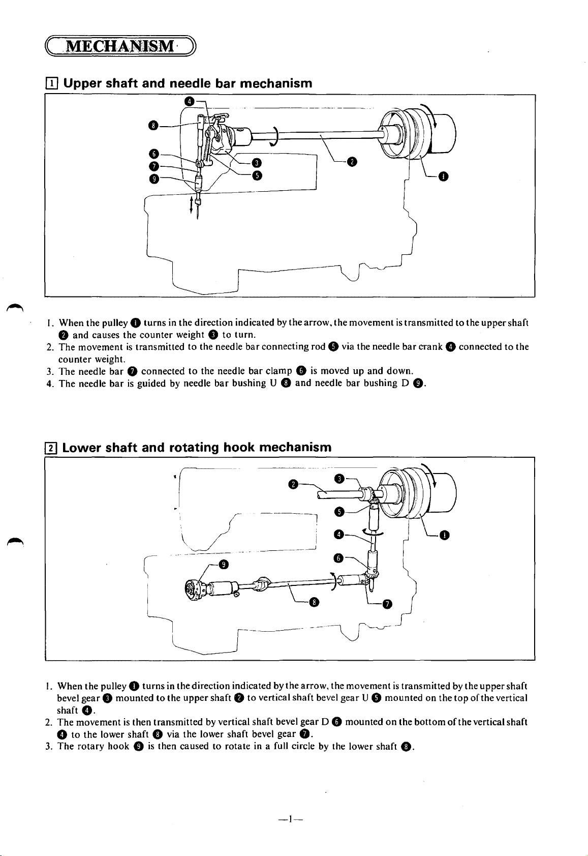
[I] Upper shaft and needle bar mechanism
I. When the pulley 0
8
and
causes the
2.
The
movement
counter
3.
The
The
4.
weight.
needle
needle
bar
bar
turns
in the direction indicated by
counter
is
transmitted
weight 8
8 connected
is
guided by needle
to
the needle
to
the needle
to
turn.
bar
bar
bushing U 0
the
arrow,
connecting rod 8 via the needle
bar
clamp 8 is
and
moved
needle
[I] Lower shaft and rotating hook mechanism
the
movement
up
bar
is
bar
and
down.
bushing D
transmitted
crank
8 connected
0.
to
the
upper
shaft
to
the
I. When the pulley 0
gear 8 mounted
bevel
G.
shaft
2.
The
movement
8
to
the
lower
3.
The
rotary
hook 0
turns
in the direction indicated by
to
the
upper
shaft 8
is
then
transmitted by vertical shaft bevel
shaft
0 via the lower shaft bevel
is
then caused
to
rotate in a full circle by the lower shaft
to
vertical
the
arrow, the movement
shaft
bevel
gear
D 8 mounted
gear
8.
-I-
gear
U 8
is
transmitted by the
mounted
on
the
on
the
bottom
0.
upper
top
of
the vertical
of
the vertical shaft
shaft
Page 4
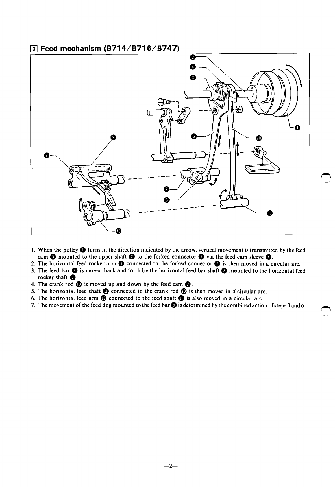
[I] Feed mechanism
•
(8714/8716/8747)
----
---
I. When the pulley 0 turns in the direction indicated by the arrow, vertical movement
cam
8 mounted
2.
The
horizontal feed rocker
3. The feed
rocker shaft
4.
The
5.
The horizontal feed shaft & connected
6.
The
7.
The movement
bar 8 is
crank rod fi)
horizontal feed
to
the
upper
shaft 8
arm
8 connected
moved back and forth by the horizontal feed
to
the forked connector 8 via the feed cam sleeve
to
8.
is
moved up and
arm
Cl
connected
of
the feed dog mounted
down
by
to
the
to
the feed shaft &
to
the feed
the feed cam
crank
----
the forked connector 8
rod ~ is
bar 8 is
_...---
is
then moved in a circular arc.
bar
shaft 0 mounted
8.
then moved
is
also moved in a circular arc.
determined by the combined action
in
i circular arc.
is
transmitted by the feed
G.
to
the horizontal feed
of
steps 3 and 6.
-2-
Page 5
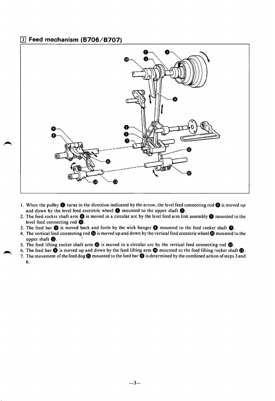
(}] Feed mechanism
(8706/8707)
.
~
I. When the pulley 0 turns in
and
down
by
the
level feed eccentric wheel 8
2.
The
feed rocker
level feed connecting rod
3.
The
feed
4.
The
vertical feed connecting
upper
shaft
5.
The
feed lifting
6.
The
feed
7.
The
movement
6.
shaft
bar 0 is
f).
rocker
bar 0 is
oft
arm
moved back
shaft
moved up
he feed
dog
the
direction indicated by the
mounted
0 is moved in a circular
8.
and
forth by the wick hanger 0 mounted
rod
6)
is
moved up
arm
• is moved in a circular
and
down
by the feed lifting
G)
mounted
to
the feed
and
arrow,
to
arc
by the level feed
down
by the vertical feed eccentric wheel
arm
bar 0 is
the level feed connecting rod 8
the
upper
shaft
f).
arm
link assembly 0 mounted
to
arc
by the vertical feed connecting rod 6).
4D
mounted
determined by the combined action
to
the feed
the
rocker
shaft
Gi)
mounted
feed lifting rocker shaft
of
is
moved up
to
f).
steps 3
to
the
the
G)
and
.
-3-
Page 6
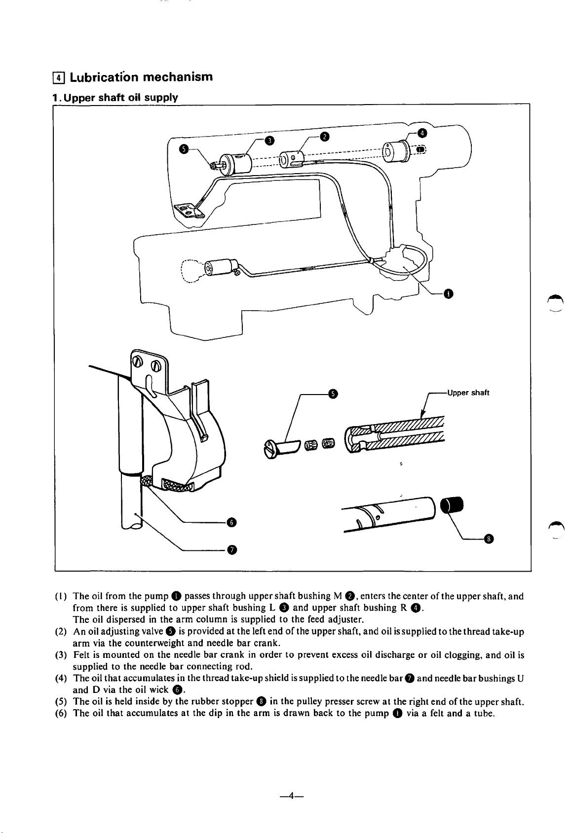
[!] Lubrication mechanism
1.
Upper shaft oil supply
(I)
The
oil from the
from there
The
oil dispersed
(2) An oil adjusting valve
arm
via the counterweight
(3) Felt
(4) The oil
(5)
(6)
is
mounted
supplied
and
The
The
to
that
D via the oil wick
oil
is
oil
that
pump
is
supplied
in
on
the needle
the needle
accumulates in the thread take-up shield
held inside by the
accumulates
8 passes
to
upper
the
arm
8
is
provided
and
bar
connecting rod.
8.
rubber
at
the dip in the
through
shaft bushing L 8
column
needle
bar
is
supplied
at
the left end
bar
crank
stopper
upper
crank.
in
8 in the pulley presser screw
arm
shaft bushing M
and
to
the feed adjuster.
of
the
order
to
prevent excess oil discharge
is
supplied
is
drawn
8,
upper
shaft bushing R
upper
shaft,
to
the needle
back
to
enters the center
and
oil
is
barO
at
the right end
the
pump
8 via a felt
of
8.
supplied
or
oil clogging,
and
Upper shaft
the upper shaft,
to
the
thread
and
needle
bar
bushings U
of
the
upper
and
a tube.
and
take-up
oil
is
shaft.
-4-
Page 7
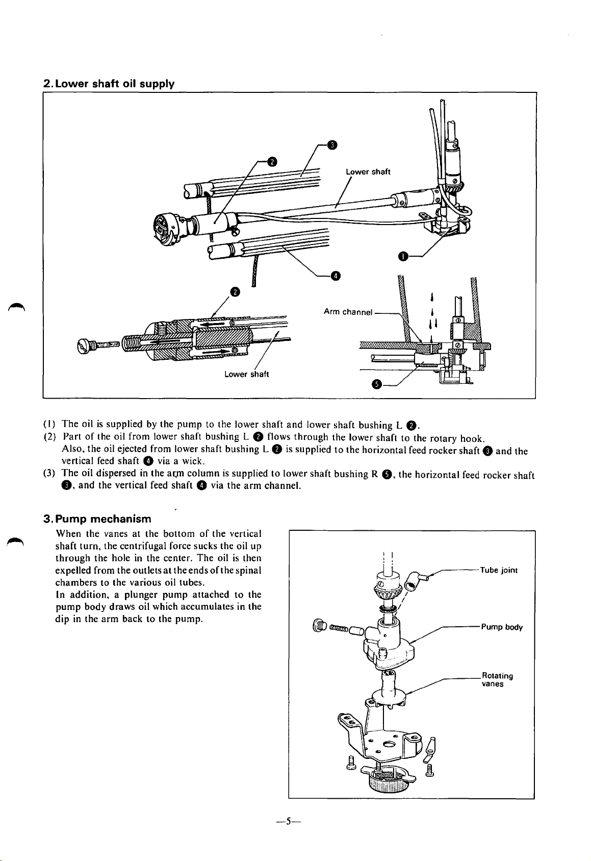
2.
Lower shaft oil supply
Lower shaft
(I)
The
oil
is
supplied
(2)
Part
of
the oil
from
Also,
the
oil ejected
vertical feed
The
(3)
0,
oil dispersed in
and
shaft
the
vertical feed
8 via a wick.
3. Pump mechanism
When
the
vanes
at
the
shaft
turn,
the
centrifugal
through
expelled
chambers
In
pump
dip
the
hole
in the center.
from
the
outlets
to
the
various
addition, a plunger
body
draws
oil which
in
the
arm
back
by
lower
from
the
to
the
the
pump
shaft
lower
ar.,m
column
shaft
bottom
force
sucks
at
the
ends
oil tubes.
pump
attached
accumulates
pump.
to
bushing
shaft
8 via
of
the
The
oil
of
the
lower
bushing
is
supplied
the
vertical
the
oil
is
the
spinal
to
in
L
f)
arm
up
then
the
the
shaft
and
flows
L
f)
is supplied
to
lower
channel.
lower
through
shaft
shaft
the
lower
to
the
bushing
bushing
shaft
horizontal
R
0,
L
f).
to
the
feed
the
horizontal
rotary
rocker
----Pump
____
hook.
shaft 0 and
feed
rocker
body
Rotating
vanes
the
shaft
-5-
Page 8
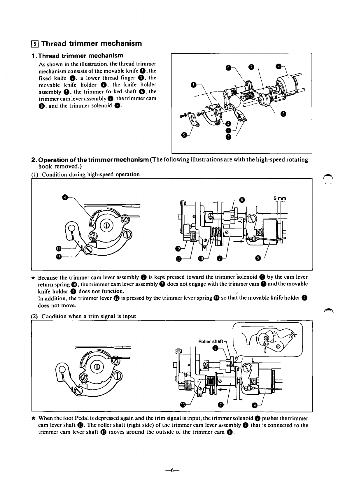
(}] Thread trimmer mechanism
1 . Thread trimmer mechanism
As shown
mechanism consists
fixed knife
movable knife holder
assembly
trimmer cam lever assembly
0,
2.
Operation of the trimmer mechanism(The following illustrations are with the high-speed rotating
hook
(I)
Condition during high-speed operation
in
the illustration, the thread trimmer
0.
a lower thread finger
8.
the trimmer forked shaft
and
the trimmer solenoid
removed.)
of
the movable knife
G. the knife holder
8,
the trimmer
8.
0,
8.
8.
the
the
the
cam
* Because the trimmer cam lever assembly 8
f),
return spring
knife holder
In addition, the trimmer lever 8
does not move.
(2) Condition when a trim signal
* When the foot Pedal
cam lever shaft
trimmer
cam
the trimmer cam lever assembly 8 does not engage with the trimmer
8 does
lever shaft
not
function.
is
pressed by the trimmer lever spring
is
input
is
depressed again
G).
The roller shaft (right side)
G)
moves
around
and
is
kept pressed toward the trimmer 'solenoid 8 by the cam lever
the trim signal
of
the trimmer
the outside
of
cam 0 and
,.
CD
so
that
the movable knife holder 8
is
input, the trimmer solenoid 8 pushes the trimmer
cam
lever assembly 8
the trimmer
cam
0.
that
the movable
is
connected
to
the
-6-
Page 9
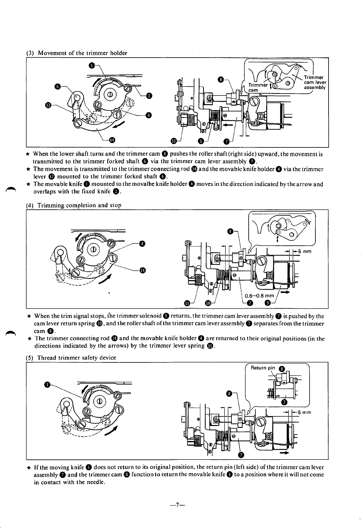
(3) Movement
*
When
transmitted
*
The
movement
lever 0
*
The
movable knife 0
overlaps with the fixed knife
(4)
Trimming
the
lower shaft
to
mounted
completion
of
the
the
trimmer
is
transmitted
to
trimmer
turns
the
mounted
holder
and
the
trimmer
forked
trimmer
shaft
to
the
trimmer
forked
to the movalbe knife
8.
and
stop
cam
0 pushes the roller
8 via the
connecting
shaft
8.
shaft
(right side)
trimmer
holder
cam
rode
lever assembly
and
the movable knife
8.
8 moves in the direction indicated by the
upward,
holder
the
movement
8 via the
arrow
is
trimmer
and
* When
*
(5)
the
trim signal stops, t'he
cam
lever
return
spring
G),
came.
The
trimmer
directions indicated by the
Thread
connecting rod
trimmer
safety device
0
* If the moving knife 0 does
8
and
the
the
trimmer
needle.
assembly
in
contact
with
trimmer
and
the toller
fD
and
arrows)
not
return
cam
solenoid 8 returns, the
shaft
oft
he
the movable knife
by
the
trimmer
to
its original position, the
8 function
to
return
trimmer
lever
cam
holder 8 are
spring
the
movable knife 0
trimmer
cam
lever assembly 8
lever assembly 8 separates
returned
to
their original positions (in
CD.
return
pin (left side)
to
a position where it will
of
the
is
pushed by the
from
the
trimmer
trimmer
cam
lever
not
come
the
-7-
Page 10
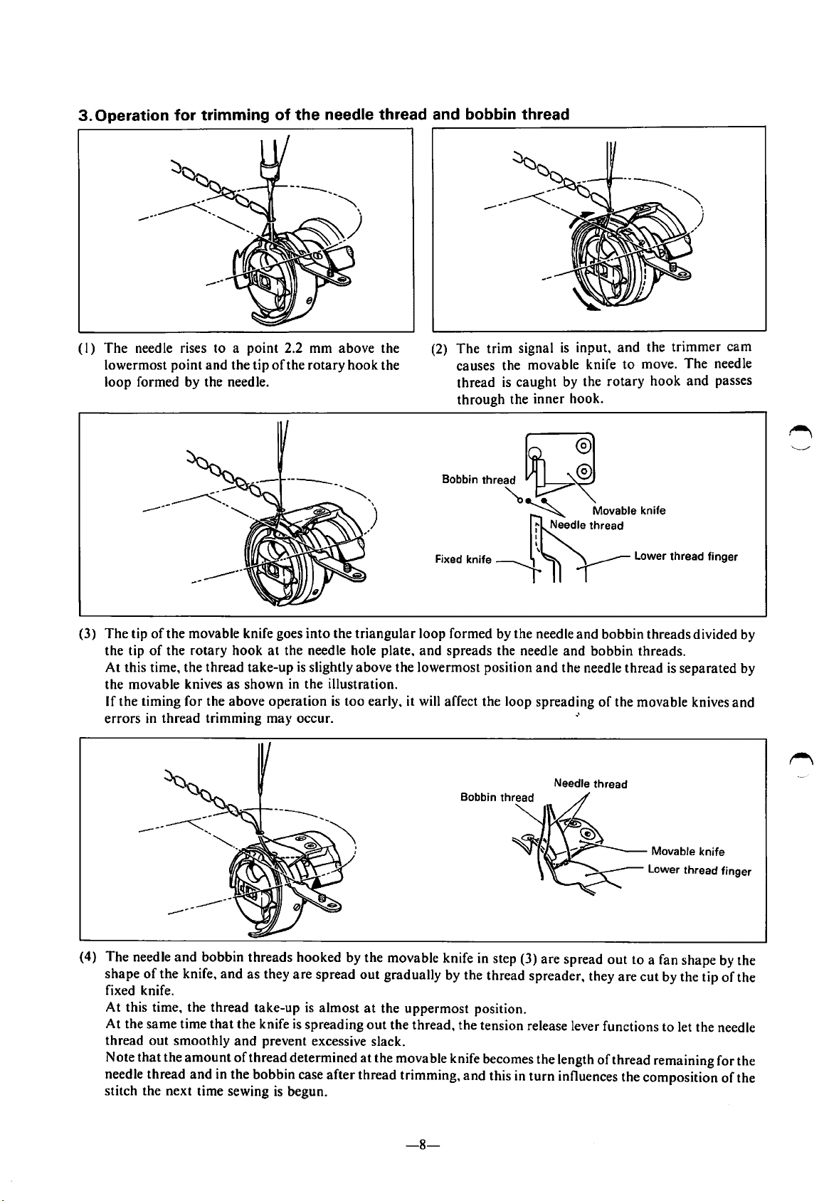
---
(I)
The
needle rises to a point 2.2 mm above the
lowermost point and the tip
loop formed by the needle.
----~~
of
the
rotary
hook
the
(2)
The
trim signal
causes the movable knife
is
thread
through
Bobbin
caught
the inner hook.
thre~~
is
input.
by the
and
to
rotary
the
move.
hook
trimmer
The
and
cam
needle
passes
(3)
The
tip
of
the movable knife goes
of
the tip
At
the movable knives
If
the timing for the above operation
errors in
the rotary hook
this time, the thread take-up
as
thread
trimming may occur.
into
at
the needle hole plate,
is
slightly above the lowermost position
shown
in
the illustration.
~
~
Needle thread
I
I
Fixed knife r
the
triangular
is
too early. it will affect the loop spreading
loop formed by the needle and
and
spreads the needle
'
and
Needle thread
Movable knife
bobbin
and
bobbin threads.
the needle thread
of
·'
threads divided by
the movable knives
is
separated by
and
(4)
The
needle
and
bobbin threads hooked by the movable knife in step (3)
shape
of
the knife.
fixed knife.
At this time, the thread take-up
At the same time
thread
Note
needle thread
stitch the next time sewing
out
that
smoothly
the
and
as
that
the knife
and
amount
and
of
thread
in the bobbin case
they
are
spread
is
is
spreading
prevent excessive slack.
determined
is
begun.
out
almost
at
out
at
after
thread trimming,
gradually by the thread spreader, they
the uppermost position.
the thread, the tension release lever functions to let the needle
the movable knife becomes the length
and
this in
-8-
are
spread
turn
influences the composition
out
of
thread
to
a fan shape by the
are
cut by the tip
of
the
remaining for the
of
the
Page 11

11]
Thread tension release lever
mechanism
*
When
trim
signal
functions. the tension release plate 8 pushes the
tension release
8
and
the tension release wire 0
tension disc.
When
the
needle
no
longer flows
the
tension disc closes.
(8707
is
input. the
bar
8 via the tension release lever
upper
to
the
/8716/8747)
trimmer
stop
signal
thread
trimmer
solenoid 0
and
is
input,
solenoid,
opens
current
the
and
[I] Thread wiper mechanism
(8707
* When
a delay
functions.
thread
neelde
thread
When
thread
spring.
/8716/8747)
the
needle
upper
of
85
ms,
the
thread
wiper 8 via
thread
trimming.
the
wiper
is
current
is
returned
wiped
stops
stop
signal
is
input,
and
then
the
wiper lever 8 moves
the
grooved link
on
top
of
the
material
flowing
to
to
the
solenoid,
its original position by a
there
solenoid 0
the
0.
and
the
after
the
is
·
[!]
Quick-back mechanism
•
•
*
When
the
quick-back switch
solenoid
pulled via the solenoid lever 8
link
downward.
While
machine does reverse stitching. When
released, it
return
stitching.
0 functions. the solenoid lever plate 8
0.
and
the reverse lever 8
the
quick-back switch remains pressed, the
is
returned
spring
and
the
is
to
its original position
machine resumes
0
pressed, the reverse
is
and
the connecting
is
pulled
the
switch
is
by
a
forward
[!]
Automatic presser lifter mechanism
* When the
lifter solenoid
presser
lifter link
*
When
lightly,
the presser lifter link 8 returns,
drops
power
switch
0 functions
bar 8 is
pressed
is
turned
(ON)
upward
and
8.
the
upper
part
of
the foot
the
presser lifter solenoid 0 becomes
back
down.
pedal
on,
the
via
and
the
the
is
the
presser
knee lifter
presser
depressed
OFF,
presser
-9-
Page 12

CDISASSEMBLY
I.
Loosen the set screw 8
2.
Remove the three screws
3. Remove the five screws 0
4. Remove the two screws
5.
Remove the oil
6. Loosen the set screw
7. Remove the slide plate
8. Remove the two screws 6'.
cap
Gi)
CB
and
0.
and
0.
and
and
the oil cap
and
e.
and
-~
remove the needle G. (Loosen the set
and
then remove the face plate 8
then remove the side cover
then remove the oil stopper plate
CD.
remove the tension regulator assembly
then remove the needle plate
and
0.
48.
and
remove the thread wiper.)
the packing
0.
0.
•.
II)
Presser
I. Loosen the two set screws 8 and remove the feed
assembly.)
2. Loosen the set screws
holder.)
3. Remove the screw
4. Loosen the set screw 0
5. Remove the presser
8.
bar
0
and
remove the presser foot
and
then remove the presser spring
and
remove the presser
CD
by extracting it from the
dog
G. (Use the presser lifter lever
8.
(Remove the screw,
bar
bar
clamp fl).
top
of
O.
the presser spring
the
arm.
to
raise the presser
and
then remove the thread wiper
8.
and
the washer
0.
-10-
Page 13

[I) Rotary hook
l. Tilt the machine.
2.
Remove the bobbin case
3. Remove the screw
4. Loosen the three set screws
f).
and
0.
then remove the rotary
G
and
remove the
f)
~~~"L,..~~-·
r---"\:'~·
hook
position bracket.
rotary
hook
0.
!"'.,
[I] Thread
trimmer
0
f)
Remove the screw
I.
Push
the
2.
screws
Remove the screws
3.
Remove the screw
4.
Remove the screw 0
5.
Remove the bolt
6.
trimmer
Remove the
7.
Remove the screw e.
8.
Remove the screw
9.
Move
10.
thread
G where they
connecting rod
trimmer
the
trimmer
41.
Loosen
II.
solenoid side).
Remove the collar
12.
the cushion
Remove the screw
13
.
the
set screw G),
fJ.
0.
and
then remove the fixed knife
trimmer
41).
connecting rod 0 in the direction indicated by the
can
be seen.
0.
and
then remove the movable knife
8.
and
then remove the lower
on
the thread
and
then remove the knife holder assembly
0.
lever spring G).
and
then remove the thread tension lever fl.
~.
and
then
cam
lever assembly
and
fi,
the
cam
f),
and then remove the
trimmer
remove the
Gil
then remove
lever
return
f).
arrow,
0.
thread
lever 0 side.
trimmer
in the direction indicated by the arrow,
the
trimmer
spring
fJ,
trimmer
lever
finger
solenoid
cam
lever
the
trimmer
0.
CD.
the
0.
0.
the movable knife holder fl,
shaft
f)
toward
cam
lever assembly e. the washer
trimmer
leverspringfl),
and
then position the two
and
then remove the
the right side (the
and
and
stop
trimmer
f),
the forked
the
ring
and
shaft
••
-11-
Page 14

[I] Feed mechanism
(8706/8707)
I.
Remove the wick
2.
Loosen the two set screws 0
3. Loosen the two set screws 8
arm
8.
4.
Tap
wedges
feed lifting rock shaft
5.
Loosen the two set screws
6. Remove the wick
7.
Loosen the set screw e
8.
Tap
wedges into the notches in the feed rock
rocker shaft j toward the left. (The oil rejector
into
the notches
0.
8
toward
fD
from the feed
on
on
the right side
on
the feed lifting rock shaft
oft
he feed lifting rock shaft
the left side.
CD
on the right side
bar
the feed rock shaft
arm
of
the feed lifting rock shaft
arm 8 and
arm 8 and
(The
oil rejector 8 and the feed lifting
of
the feed rock shaft
G).
arm • and
shaft
arm
fD
and
the two set screWS·"·
Cl
and
the feed
the three set screws 0
the feed lifting
G),
the feed
bar
arm
8,
and then remove the collar
arm
8,
and
arm
8 will also come off.)
and
then remove the collar
on
the feed
bar
arm
G),
and
then remove the feed
G) will also come off.)
on
the feed lifting
then remove the
•.
bar
arm
G).
8.
-12-
Page 15

[II Feed mechanism
(8714/8716/8747)
I. Loosen the
2.
Remove the two set screws
3. Loosen the set screw
4. Loosen the set screw
5. Remove the two set screws
6. Loosen the set screw
and
feed
[!]
Needle bar mechanism
Needle bar
bushing U
bar
nut
8.
0.
and remove the screw
8,
rotate the
8.
8.
disconnect the
8.
and
taper
and
remove the feed
G),
and
•
•
•
•
8.
remove the oil
pin
8.
and
arm
remove the oil
taper
pin
fD,
stopper
remove the feed lifting rock shaft 8
pin
stopper
and
G.
and
GD.
48.
remove the feed rock shaft fl, feed rock shaft
feed lifting
arm
arm
0.
tD.
I. Tilt the machine.
2. Remove the needle
3. Remove the wick 8 from the
4. Loosen the set screw
5. Remove the oil cap
6. Remove the oil
crank
G),
needle
bar
8.
8.
cap
and
bar
connecting rod
thread guide
and
remove the needle
loosen the set screw 8
loosen the two set screws
top
G.
of
the needle
CJ,
and
wahser
bar
bushing
bar
8.
and
remove the thread take-up
8.
Now remove the thread take-up rocking
and
U.
needle
bar
e.
-13-
clamp
8.
(Remove the slide block.)
support
pin
arm
0.
GD.
needle
bar
Page 16

~
ASSEMBLY )
[I] Needle bar
Screw flat
Reference
lines
••
J~t
~~
/·-=
Line
I.
Install the thread take-up
washer 8 with the set screw
arm
assembly
8.
0.
the needle
* Refer to the above illustration for the position
Thread
2.
3. Fit the thread take-up lever
with the set screw
4. Fit the block 0 into the groove,
and
(Fit
5. Fit the needle
••
6.
Pass the wick
7.
Turn
8. Align the second reference line from the
the wick through the
thread
support
take-up lever
shaft 8
8.
and
then fit the needle
the block
the block into the groove with the chamfered side toward the inside.)
the pulley
0.
bar
0 into needle
through
and
set the needle
bar
from needle
bushing U
bar
bushing U
bar
to the lowermost position.
bottom
oe.
@Threading the wicks
bar
of
the needle
support
through
fD
from the
the
fD.
on the needle
crank
thread
bar
clamp 8
(Refer
f),
the needle
bar
crank
shaft
8.
take-up
through
top.
and
then pass
to
the illustration.)
bar
fD
with the
f)
(Refer
arm
B706 DA x 1
B707 DA X 1
B714
B716 DA
B747
bar
connecting rod
screw flat.
to
the illustration.)
assembly
the neelde
it
through the needle
bottom
end
0.
bar
of
DB
X 1
DB
DA
DB
X 1
X 1
X 1
DB
DB
X 1
X 1
X 1
----
0.
and
and
then secure it
connecting rod 0
bar
needle
bar
bushing
the
clamp
~
'-___/
(
l)
Thread the wick
assembly
(2)
Thread
the thread take-up
(3) Insert a length
pull
(4) Align the end
thread take-up
of
8.
the wick into the machine while installing
out
the wick as shown
the wick into the oil hole.
through
of
piano wire into the oil hole
of
the wick with the edge
arm
the thread take-up
arm
assembly
in
assembly 8
8.
the illustration.
and
insert the rest
of
arm
and
the
(I)
Thread
needle
(2) Manually
up
(3) As shown in the illustration, insert the wick until
contacts the
assembly
(4) Insert the end
-14-
the wick through the
bar
to
the
bushing.
turn
the pulley
uppermost
top
0.
of
the wick into the oil hole.
Piano
wire
Wick
upper
and
set the thread take-
position.
of
the thread take-up
end
of
the
it
arm
Page 17

II]
Feed mechanism
(8706/8707)
•
~
I
I
I
I•
Feed dog
I. Install the needle plate 0 with the screws
2.
Tilt the machine.
3.
Mount
lifting rock shaft
4.
Mount
easily with no play.
Connect
5.
6.
Fit the forked
7.
Mount
rock shaft
8.
Fit
play.
* Secure the feed rock shaft·arm
easily.
* Secure the feed lifting
divides the groove in the needle plate 0
the feed
9.
Connect
* Secure the feed lifting rock shaft
fJ)
the feed lifting rock shaft 8
arm
8.
the set
collar 0 onto
the wick 8 to feed lifting rock shaft
part
of
the feed
the feed rock shaft e (from the left side), the feed
arm
41.
the feed rock shaft
dog
G)
the wick 8 to the feed lifting rock shaft
moves easily.
4D
into
arm 8 and
projects I mm
(from
the feed lifting rock shaft
bar
f1
onto
the set collar
4D
with the screw
the feed
front
out
of
the needle plate
arm
8 with the screws
8.
the left side), the feed lifting
8.
and
then secure it with the screw 8 so
8.
the roller
0.
and
bar
arm
to
(Refer
then secure it with the screw 8 so
41
in a position where the level feed
back
to the illustration below.)
on
the end
bar
$ with the screws
and
left
of
arm$.
to
right. In addition, tighten the screw
0.
8.
(Refer
to
the diagram below.)
G)
in
a position where the vertical feed connecting rod
arm
8.
the oil rejector
the feed lifting
the oil rejector
fD
in a position where the feed
arm
G),
and
that
it moves easily with no
arm
•
•
•
8.
and
the feed
that
it moves
8.
the horizontal feed
link assembly moves
dog
G)
CD
so
that
Ql)--
-15-
Page 18

II]
Feed mechanism
(8714/8716/8747)
~
1
I
I
I•
•
Feed dog
I.
Install the needle plate 0 with the screws
2.
Tilt the mac}line.
3.
Mount
4.
Mount
5.
Secure the feed rock shaft
move easily with no play
the
6.
Fit the forked shaft 0 into the forked
arm
7.
Mount
8.
Mount
9.
Mount
with not play
10.
Fit
slides easily.
II.
Fit the screw
12.
Install the oil
13.
Turn
needle plate.
14.
Set
15.
Loosen the screw
plate in
the
taper
pin 8
the feed
throat
pin
4D
the oil
the
the feed lifting rock shaft 8
the side block
the pulley
the length control dial
half
dog 8 onto
plate into left
with the set screw
stopper
taper
pin $
on
the
G)
fJ)
into the crank rod
stopper
and
front to back.
onto
on
and
fl
onto
taper
of
the feed lifting
fl
loosen the screw
fa
and
adjust the feed rock shaft 8 so
the
the feed
8.
the feed rock shaft
the
taper
right.)
Q).
with the screws
the
pin
$.
with the screws fl.
to
the highest setting
arm
pin
arm
and
fD
fa
bed.
bar
8.
part
bed.
arm
and
to
8.
8 with the screws
arm
O.
(At
this time, adjust the feed
of
the feed rock shaft
CJ).
the feed lifting
C1
into the forked
the feed lifting rock shaft fl,
adjust the feed
and
turn
and
the feed
arm
Cl
part
dog
the pulley.
that
the feed
8.
arm
with the set screw
of
8 so
1/
bar
8.
dog
0.
and
the feed
and
that
it extends I mm
dog
8 divides the groove in the needle
1/
with the set screw
8 so
that
it
then secure the feed rock shaft
G)
so
bar
8.
and
then secure it with the
f)
divides the groove in
that
they move easily
then confirm
out
of
so
the
that
top
that
nut
ofthe
•
•
G
they
it
8.
-16-
Page 19

fl]
Thread trimmer
I. Fit the forked shaft 0 into the
2.
Mount
cushion 8 onto
the
3. Fit the
4.
Tighten
5.
Mount
Mount
trimmer
6.
Mount
releasing lever.)
7.
Mount
trimmer
8.
Mount
screw
9.
Mount
10.
Mount
II.
Mount
12.
Mount
13.
Hook
14.
Confirm
the collar
trimmer
stop
the set screw
the
the solenoid so
solenoid
the tension releasing lever
the movable knife
connecting rod 8> with the bolt
the
8.
the
cam
the
arm
bed,
cam
lever assembly 8 into the fork
ring 0
thread
trimmer
onto
~.
trimmer
that
CD
is
as
lever
the
solenoid
the gap between the
small as possible.
holder
spring~
fl.
the
thread
the lower thread finger
the fixed knife
the movable knife
the
trimmer
that
the
trimmer
f)
lever
position
connecting
to
f1
spring~
of
* Move the lower thread finger
rotary
hook.
arm
bed.
lever return spring
and
then
mount
trimmer
cam
4D
to
CD
with the screw
4D
onto
the
the
lever
the
arm
8.
trimmer
shaft
arm
trimmer
bed,
Cl).
and
the
trimmer
rod 8 to
fJ
to
the
arm
the
arm
bed with the screws fi.
to
the movable knife holder
onto
the
the
fJ
towards
trimmer
cam
the movable knife in
the
bed with the screw fi.
trimmer
is
correct.
the
trimmer
of
the forked
cam
cam
lever shaft 8
shaft
8.
bed with the screw
cam
lever shaft 8
48.
(Refer
to
p.23 for instructions
and
then
mount
lever
fJ
onto
the forked
thread
lever fl.
trimmer
4D
with the screws
order
lever assembly G. the
(after
fitting
washer8
the
slide block 8
0).
$.
and
the solenoid lever
on
adjusting the tension
the knife holder assembly
shaft 0 and
lever
fJ
with
1).
to
maintain the space between it
secure them with the
the
screw tl.
41
and
G)
on
(and
and
the
of
the
then
the
-17-
Page 20

~
Thread trimmer timing adjustment
I.
Thread
*
Turn
above
solenoid
the roller shaft contacts the
trimmer
roller shaft
lever assembly returns.
2.
Fixed knife
*
The
knife
roller shaft
moves
the movable knife holder
mating
If
thread
end
e agree with the position
moves
[!]
Bottom of the needle bar bushing
trimmer
the pulley,
the lowermost position, press the thread
CD
cam
end
of
cam
position
and
then when the needle
and
adjust the thread
G)
and
the end
is
0.6
to
0.8
mm
and
moving knife position
the fixed knife e
adjustment
trimmer
cut
out
of
the
when the thread
and
the blade
e must be in the position shown in Fig. A when
of
up
the
mark
the
positions
trimmer
of
the fixed knife e
up
the thread
Rotary
the thread
thread
on
the kpife
do
not agree with those in Fig. A. move the
lever
hook
trimmer
trimmer
fD
holder
fJ)
and
and
trimmer
cam
G).
must be in alignment with the
assembly
tighten the screw
the blade
in
Fig. A when the roller shaft
cam
41
•
em]
Reference
lines
~
""
-
-
-
-
-.....
-
-:
-
bar
cam
part
of
cam
and
the end
trimmer
adjustments
of
the movable
cam
lever assembly 0
(The
mating
$).
f)
of
the movable knife
G).
rises 5 mm
trimmer
G)
so
that
the
thread
of
the
cam
the
mark
on
so
that
the
~j
~·[;
Lower shaft
fJ
1-1.5
mm
•
B706 DA X 1
B707
B714 DA X 1
B716
B747
I.
Mount
2.
Mount
3.
Mount
4.
Mount
5.
Turn
with the
6. Align the
At this time,
is 0 to
7.
Mount
Mount
8.
9. Adjust the feed timing.
Turn
plate when the feed
surface
*
Confirm
thread
DA X 1
DA
X 1
DB
X 1
~
the needle plate.
the
rotary
hook 0
the
rotary
hook
the needle
the pulley so
bottom
rotary
0.5
mm
the needle plate.
the slide plate C).
the pulley forward
of
the needle plate. (Refer
that
being used
of
hook
adjust
and
the
gap
bar
that
the needle
so
the distance between the needle 8
dog
between the rotary
to
pass
DB
~~;~re
X 1
DB
X 1
DB
x 1
DB
X 1
onto
the lower shaft 0
position bracket 0 with the screws
thread guard 8
the needle
bar
point with the center
that
the distance between the
and
adjust so
finishes the feed
through
onto
the needle bar,
bar
rises from the lowermost position
bushing as
of
that
the tip
and
begins
to
the timing
hook
easily.
and
shown
the needle
rotary
of
the needle
to
retract
adjustment
position bracket 0
-18-
·,~>'o
~
•
secure it with the screw
8.
and
then
secure the needle 8 with the set screw
and
in the illustration.
8.
hook
point
and
the
and
the
and
on
rotary
is
the tip
p.21.)
hook
aligned with
of
the feed
and
the
rotary
•
8.
align the needle
upper
edge
of
the
tip
is
0.05
to
the
upper
surface
dog
is
aligned with the
hook
0 is
bar
reference line
eye
of
0.1
mm.
of
the needle
just
enough for the
8.
the needle
upper
Page 21

[I]
Presser
mech~r:'_ism
•
I.
Insert the presser
2.
Mount
presser
3.
Mount
foot adjustment screw
(Mount
4.
Mount
5.
Adjust the height
the presser
bar
guide bracket
the washer
the thread wiper holder onto the presser
the presser foot 8
bar
0 from the
bar
guide bracket 8
G.
8,
the presser bar spring
8.
onto
the presser
of
the presser foot 8
--
top
of
the arm.
onto
the groove in the
8,
and
the presser
bar
0 and secure it with the screw.)
bar
8 with the screw
to
approximately 6 mm.
arm,
and
bar
spring guide
then pass the presser
8,
and then tighten the presser
8.
Approx. 6
bar
0 through the
mm
f
.~
[]]Cover
Screw_./
l'l~
Thread
I.
Mount
(The thread take-up spring operating range
2.
Mount
3.
Mount
4.
Mount
5.
Mount
(Mount
the tension regulator assembly 0 with the screw
the oil
the oil cap 8 and the oil cap
the rear cover 8
the face plate
stopper
the thread wiper with the screw.)
plate 8 with the screws
and
the packing 8 with the screws C).
f)
and
the packing
·
wi~er
is
8 mm
. _
8.
8.
CD
with the screws
G.
and
the tension
CB.
is
20 to
30
kg.)
-19-
Page 22

[I] Needle and rotary hook timing adjustments
In
order
for the tip
point. the needle
1 . Needle bar height
of
the rotary hook
and
rotary hook must be correct.
to
catch the loop
in
the needle thread when the needle rises from the lowest
•
Reference line
*
Turn
the pulley slowly.
bottom
• Loosen set screw 8 and align this second reference line with the bottom
reference line on the needle
adjusting. firmly tighten set screw
and
lower the needle bar 8
bar 8 is
8.
to
the needle
aligned with the bottom
down
position. Confirm
of
the needle
of
the needle
bar
that
the second from
bushing.
bar
bushing
8.
After
2.
Rotary hook position
0
Reference line
*
Turn
the pulley slowly.
bushing
center
• Loosen set screw 8 and
to
8.
With the needle
0 and
rotary
hook
that
and
align the
bar
the needle 0 to rotary hook point 8 gap
after
point 8 gap to between 0.05 -
bottom
in this position. check that the rotary hook
aligning the rotary
reference line on the needle
hook
point 8 with the needle center
0.1
mm. Firmly tighten set screw
bar
is
between 0.05 -
8 with the
pointe
0.1
bottom
is
of
the needle
aligned with the needle
mm.
0.
adjust the needle 0
8.
* Always perform the steps for rotary hook lubrication adjustment after replacing the rotary hook.
bar
-20-
Page 23

II]
Feed dog height adjustment
••
Feed dog height
I.
The standard height
thick materials
2.
Adjust the feed
needle plate surface, and move the feed lifting
Feed dog angle
I.
The
standard angle
is
position)
• In
• In
2.
In
order
directions indicated by the arrows.
obtained by matching the
order
to prevent packering. raise the feed
order
to prevent the material from slipping. slant the feed
to adjust the feed
* When the feed
of
the feed
1.2
mm (when the stitch length
dog
height by loosening the screw 8 when the feed dog 8
of
the feed
dog
angle has been adjusted, check
dog
for sewing thin materials
dog
8 (horizontal
"0"
dog
angle, loosen the screws 8 and then
mark
A
.
~
j B
••
~
A
===::l
,---
~
__..,
F1
B
~
is
0.8 mm. for medium materials
is
set
to
the maximum).
arm
0 up and down.
to
the
needle plate surface when the feed
of
the feed plate shaft 8 with the notch
dog
8 in the forward direction.
dog
to
confirm
that
r-_
==:::::1
~
_./
is
at
8 in the forward direction.
turn
the feed plate shaft 8 90° in the
its height has not changed.
Rises
in
the forward direction
t=:=
Descends in the forward direction
c::::::::=
1.0
mm,
and
for
its height position from the
dog
is
at
its highest
on
the
feed
bar
arm
8.
I~
[I) Feed timing adjustment
Feed
dog~
~
I.
Turn
the pulley manually; the area
alignment with the
tip
of
the feed
2.
If
the
feed timing
If
the feed
turns; if the feed
machine turns.
3.
After adjusting the timing, tighten the screw securely.
dog
top
surface
dog
is level with the
is
not correct, loosen the set screw 8
retracts
dog
too
early, turn the feed cam slightly in the opposite direction from which the machine
retracts
[I] Presser height adjustment
*
The
amount
when the presser foot
bar
lifter lever
Turn
the presser
Remove the cap 8 from the front cover. loosen
the screw
down
of
presser foot rise should be 6 mm
8 is raised by the presser
8.
the presser regulating screw 0
bar
8.
to
adjust it.
lifter lever
and
move the presser
8.
of
the needle between the tip
of
the needle plate when the feed
top
surface
too
late,
turn
the feed
and
lower
bar
8 up and
of
the needle plate.
of
the feed cam 8
cam
slightly in the same direction as
and
the lower edge
dog
completes the feed and retracts so
and
of
the eye should be
adjust.
that
in which the
that
in
the
-21-
6mm
Page 24

IT]
Synchronizer
1 .
Position
adjustment
adjustment
of
the
thread
trimmer
Synchronizer Adjustment (8707 /8716)
1.
Turn
off the power
(If
the hole IC's are to be adjusted.
2.
Remove the synchronizer cover.
3. Rotate the pulley towards you
must be aligned
· If the lower end
loosening the screw
4.
Turn
on
the power
22 mm above the surface
If the needle
hole IC
5.
Stop
the machine
for thin
If
the point
up
hole IC
* The needle
rise when they are moved in the opposite direction.
bar
8.
and
medium thickness materials. and
of
f).
bar
of
the machine.
it
is
important
and
stop
the needle 5 mm above its lowest point.
at
this time with the upper edge
of
the magnet 0
8
and
and
stop
does not
at
the needle-up position.
the needle does not
will lower when hole IC 8 and hole IC 8 are moved
and
the upper edge
moving the
the machine
of
the needle plate.
stop
at
this position, adjust by loosening the screw 8
stop
at
thread-trimmer
at
the needle-down positidh. At this time the needle
this position, adjust by loosening the screw 8
The
signal
18-22
that
the power first be turned off.)
of
the thread-trimmer hole IC
oft
he thread-trimmer
hole IC.
point
of
the needle must stop 9
10
-
12
mm
above
the needle plate for thick materials.
mm
hole·IC8
in
the direction
The
lower end
oft
he magnet 0
8.
are
not aligned, adjust by
bar
must
and
moving the needle-down
-II
mm above the needle plate
and
moving the needle-
of
machine rotation.
stop
18-
and
Synchronizer Adjustment (8747)
I.
Turn
off the power
(If
the hole IC's are to be adjusted, it
2. Remove the synchronizer cover.
3. Rotate the pulley towards you
must be aligned
If
the lower end
loosening the screw
Turn
on
the
4.
22 mm above the surface
If the needle
hole IC
5.
Stop
the machine
for thin
If the point
up
hole IC
* The needle
rise when they are moved in the opposite direction.
power
bar
0.
and
medium thickness materials, and
of
f).
bar
of
the machine.
is
important
and
stop
the needle 7 mm above its lowest point.
at
this time with the
of
the magnet 0
8
and
moving the
and
stop
the machine
of
the needle plate.
does not
at
the needle does not
will lower when hole IC 8 and hole IC 8 are moved
stop
at
the needle-up position.
upper
and
the upper edge
thread-trimmer
at
the needle-down position. At this time the needle
this position. adjust by loosening the screw 8
The
stop
at
this position, adjust by loosening the screw 8
edge
point
10--
that
the power first
of
the thread-trimmer hole IC
ofthe
thread-trimmer
hole IC.
of
the needle must stop 9
12
mm above the needle plate for thick materials.
be
turned off.)
hole
in
the direction
The
lower end
8.
IC8
are
not aligned. adjust by
and
moving the needle-down
-II
mm above the needle plate
and
of
machine rotation,
of
the magnet 0
bar
must
stop
18-
moving the needle-
and
-22-
Page 25

11]
Thread trimmer adjustment
1 . Replacement of the fixed knife and movable knife
*
Turn
off
the power.
ilstone
Removal
(I)
(2.)
(3) Remove the screw 8
@ If the thread
Removal
(I)
(2) Remove the screw
(3)
(4)
(5) Remove the screw
of
the fixed knife
Tip the machine
Remove the screw 0
of
the movable knife
Use the presser foot lifter lever
Turn
the pulley until the needle
Press the thread trimmer connecting
screw
8 can be seen.
of
its side.
trimmer
8
and
the rotary
and
the fixed knife
should need sharpening, sharpen the fixed knife 8 as shown in Fig. A.
to
lift the presser foot.
and
the needle plate
bar
8 and the movable knife
hook
position bracket
8.
8.
is
at
its highest position.
bar
8 in the direction
8.
8.
of
the arrow
and
stop
in
at
the point where the
* Remove the needle plate 8 and the movable knife 8 only after the needle has been removed.
* Assemble in the reverse
2.
Adjustment
of
order
of
disassembly.
the fixed knife, movable knife, and lower thread finger
1-1.5
mm
Fig.
8
~
~~
•
(I)
After attaching the movable knife 8 and the fixed knife
match up the marking
At this time the relationship between the end
be as shown in Fig.
If
it
is
not, loosen the screw 8 and adjust the thread trimmer lever G).
* If the above adjustment
* In
order
to
maintain the distance between the lower thread finger
finger towards the movable knife
on
the movable knife holder
B.
cannot
be performed, refer
8.
of
the fixed knife 8 and the blade
8,
depress the thread trimmer connecting rod
Cl)
with the marking on the knife holder assembly
to
thread
trimmer
and
the rotary hook, move the lower thread
-23-
of
the movable knife 0 must
timing adjustment
on
p.l6.
8,
and
CD.
Page 26

(I] Tension release lever adjustment
* Adjust the
solenoid
(tension release lever does
moving for the next 2
Confirm
at
this time.
Also, when the solenoid
that
the disc
nut
f)
so
that
the
thread
trimmer
0 moves easily for the first 0 - 2 mm
not
- 5 mm.
that
the tension disc 8 opens
is
not
is
firmly closed.
operate)
operating, confirm
and
0.5-
resists
I mm
[!]Thread
I.
Attach
presser foot
come in contact with the presser bar.
2.
Loosen the thread wiper lever screw
the thread wiper lever
grooved link
3.
Attach the thread wiper 8 so
not
come
presser foot
wiper
the thread wiper bearing 0 so
is
8
in
contact
is
adjustment
lifted with the knee lifter, it does not
f)
so
that
is
vertical
raised.
to
with the presser foot when the
that
when the
and
position
the groove
the bed surface.
that
the end
of
of
the
it does
[!] Automatic presser foot lifter adjustment (
=?:mmm
,..,~
..
~
_£dog
~Knee
o.a--O.s
I. Adjustment
Adjust so
Turn
2.
Damper
Adjust so
Se the feed
Loosen the screw
to
3.
Damper
Adjust the speed the presser foot comes down with the
adjustment screw
* When the adjustment screw 8
material).
If
damaging the material being sewn.
*
The
changes in presser foot pressure
mm
\~complying
Presser foot
of
the solenoid
that
the noise (impact noise) made by the presser foot when it
the adjustment nut 0 so
support
joint
that
the noise (impact noise) made by the presser foot when it comes
dog
in
8.
0.3-
0.5 mm, match up the
adjustment
8
this screw
above procedure
is
too loose, the presser foot will come down
lifter
bar
f)
lifter
link
and
plunger
that
the space between the solenoid
adjustment
its lowest position.
and
after
adjusting the space between the knee lifter push
damper
to
approximately 30° from the fully tightened position.
is
(I
--
3)
is
the
and
support
to
tight. the presser foot will not come down (will
standard
power supply voltage.
joint
adjustment; however, there may be subsequent variations due
•
8 with the
adjustment
too
-900;
fast, thus making
electromagnetic type)
is
lifted
and
the plunger
bar
rubber
cushion
screw 8
oo
Tighten
is
small.
f)
is
down
is
and
the presser foot lifter link
fully
Adjustable
0.6 - 0.8 mm.
small.
8.
of
the
damper
an
impact noise
8.
not
press against the
and
range
Adjust the
possibly
to
-24-
Page 27

~==T=R=O=U=B=L=E=SH====O=O=TI=N=G=G=U=I=D=E=.
:::::::::~
[I] Machine head
I Trouble I L...-..-.-1
r--
Improper needle installation
Bent needle, blunt
-
tip, blocked needle hole
Improper feed timing
-
Needle breaks
r-
Improper needle
....._
hook timing
_cause
-------~~
needle
to rotary
1~...-----c_heck
1--
Needle bias. height
1--
Needle
Is
material
1--
is
in material?
Needle
-
r-r-
'---
bar
Needle
bar
Needle to rotary hook gap
_I
fed
when needle
lift stroke
height
IL--_Solution_____._____....l
-
Reinstall properly
......____
Replace needle
f---
Adjust timing
Refer to
..
-
Hook Timing Adjustment"
Refer to
r--
Hook Timing Adjustment"
Refer to
r--
Hook Timing
Needle and Rotary
..
Needle and Rotary
..
Needle and Rotary
Adjustment"
Page I
/
/
21
20
20
20
Thread breaks
Thread frays
.---
Improper threading
Bent needle, blunt needle
-
tip, blocked needle hole
-
Improper needle installation
i-
Exc~ssive
-
tens10n
Excessive lower thread
r-
tension
....._
Loose upper thread
.---
Burr in thread path
r-
....._
Blunt needle tip
upper thread
f--
Threading
f--
Needle
1--
Needle bias, height
f--
Upper thread tension
1--
Lower thread tension
Thread take-up spring
r--
stroke
1-
Rethread properly
f---
Replace needle
r--
Reinstall properly
-
Adjust tension
- Adjust tension
Adjust take-up spring
-
Remove with sandpaper
Replace needle
/
/
/
/
/
/
/
/
-25-
Page 28

..._____T_rouble-------,J.II
L....---
_cause
-------~~~
L....---
_Check
-------~~
IL..,_____Solutio_n
....~....----..1
Page I
Skipped
stitches
-
-
-
I-I-
-
Improper
Bent needle
tip
Improper
Improper
hook
Upper thread left
short
material
needle installation
or
blunt needle
threading
to
at
needle
rotary
is
too
needle
timing Hook Timing·
and
doesn't remain
Needle bias. height
-
Needle bias, height
-
Threading
-
r--
Needle
Needle lift length
f-f--
....__
Needle
in
bar
to
lift
rotary
stroke
hook
gap
Reinstall properly
-
Replace needle
-
,....--
Rethread properly
Refer to "Needle and
1-
Hook
1--
f----
Adjust pretension
Timing
Refer to
..
Needle
Referto
"Needle and Rot'ary
Hook
Timing
Rotary
Adjustment"
and
Rotary
Adjustment"
Adjustment"
/
v
/
20
20
20
/
Upper
tighten
Lower
tighten
thred
thread
does
does
not
not
Bobbin idles and bobbin thread
is
too
-
'--
-
-
-
r--
t-
'--
short to rise
trimming
Thread
weak to lift bobbin thread
Upper
weak
Exc~ssive
tensiOn tension
Excessive upper thread
tension
Lower
weak
during
take-up spring
tension
thread
upper
thread
tension
thread
thread
is
too
too
too
Bobbin case idler prevention
-
screw
Thread
-
take-up
tension
spring
Replace idler
1--
spring
Adjust thread take-up
-
spring
Increase
tension
Decrease bobbin thread
Decrease
tension
Increase
tension
upper
upper
bobbin
prevention
/
/
thread
/
/
thread
/
thread
1/
-26-
Page 29

..__T_rouble______.l~
~_cause
______.II'----
_check
______,II~
_solution~~
Page I
Thread trimmer misses
neither upper
a.
er
thread
upper
b.
cut
lower
c.
cut
is
thread
thread
cut
or
is
is
low-
not
not
Movable
r--
do not meet
Movable
r--
are burred
Movable
-
does not move
Improper needle installation
-
Stitch skips at last stitch
upper thread trimmer does not
r--
catch upper thread
Movable
r--
do
Poor cutting
r--
and fixed knives
not
and
and
fixed knife blades
or
abraded
and
and
meet
.....
Movable
'--
do not meet
and
knives
fixed
knife
fixed
and
fixed knives
movable
by
knives
fixed
Check alignment
1--
holder and thread trimmer holder
presser i ndcx marks
Movable
t---
blades
Is
t---
f---
f---
t---
-
-
thread trimmer
output?
Needle bias
Thread take-up spring Adjust thread take-up
stroke
Check alignment
holder and thread trimmer holder
presser index marks
Movable
blades
Check alignment
holder and thread trimmer holder
presser index marks
of
thread trimmer
and fixed knife
signal
of
thread trimmer
knife
fixed
and
of
thread trimmer
Align movable
-
knives
Replace movable and fixed
-
knives ·
Check electrical circuitry
f---
Reinstall properly
-
-
spring
movable
.Align
-
knives
Replace movable
-
knives
movable
Align
r--
knives
and fixed
and fixed
and
fixed
fixed
and
23
23
v
/
v
23
23
23
thread
Upper
sewing start
casts
off
at
Insufficient tension disc
-
opening
-r--
~xcessive
Thread too thick for needle
i--
hole
Needle upper
'--
high
take-up
pretension
stop
and
thread left by thread
position
Tension disc ,opening
-
f---
Adjust tension release lever
Adjust pulley tension
24
/
Needle size
/
is
too
Thread take-up height when
machine
is
f---
position
in needle upper
-27-
stop
Delay needle up stop
-
22
Page 30

.._T_rouble______.JI
cutter does not
Thread
move
L..----1
Thread
-
output
r--
Upper thread
_cause
trimmer signal not
too
_____,II
long
L..---
_check
______,II
L.---
_solution------'--------1
Check circuits
and
Check
Page I
v
adjust pretension
v
Thread wiper does not
pull upper thread
from material
Thread wiper strikes
and
needle
return
does
up
not
Excessive material
1--
presser foot resistance with rear
I-
Early
1--
'---
....--
1-
.__
timing~
before tension disc closes
Thread wiper
too
short
Thread
wiper
too
long
Automatic
too
4uickly
and
pulls
off
operating
operating
presser foot rises
time
time
Replace with presser foot
Adjust
Adjust
Adjust
Adjust
presser foot
gap
operating
operating
operating
operating time
time
time
time
v
v
[7
[7
of
v
-28-
Page 31

BROTHER
HEAD
OFFICE:
HORITA-DORI, MIZUHO-KU, NAGOYA, JAPAN
CABLE:
TELEX:
INDUSTRIES,
No. 35, 9-CHOME,
BROTHER
BROTHER
NAGOYA,
4473696J & J59743
13090153B Printed in Japan
LTD.
467
 Loading...