

Page 1

Polycold® Portable Cryocooler
Model P-102
Operator and Installation
Manual
Part Number 174320
Page 2

Brooks Automation. Accelerating Innovation.
Information provided within this document is subject to change without notice, and although believed to be
accurate, Brooks Automation assumes no responsibility for any errors, omissions, or inaccuracies.
AcuLigner™, Align™, AquaTran™, AutoTeach™, ATR™, AXM™, Basic Blue™, BiSymmetrik™,
CenterSmart™, Cool Solutions™, Crate to Operate™, e-RMA™, e-Spares™, e-Volution™, FastRegen™,
FIXLOAD™, FrogLeg™, InLigner™, InCooler™, Interface™, Jet Engine™, LowProfile™, M2 Nano™, MiniIon™, PASIV™, PowerPak™, PerformanceBlue™, PowerPak™, PowerTools™, QuadraFly™, Radius™,
Radient™, Radient Express™, Reliance™, Reliance ATR™, RetroEase™, SCARA™, SmartPM™,
SPOTLevel™, Synetics™, The New Pathway to Productivity™, Time Optimized Trajectory™, Time Optimal
Trajectory™, Time Optimized Path™, TopCooler™, TopLigner™, Ultimate Blue™, VAC-407™, VacuTran™,
Vacuum Quality Monitor™, VQM™, Vacuum Quality Index™, VQI™, and the Brooks logo are trademarks of
Brooks Automation, Inc.
AcuTran®, AquaTrap®, Conductron®, Convectron®, the Cool Solutions logo, Cryodyne®, Cryotiger®, CryoTorr®, Fusion®, GOLDLink®, Granville-Phillips®, Guardian®, GUTS®, Helix®, Jet®, Leapfrog®,MagnaTran®,
MapTrak®, Marathon®, Marathon 2®, Marathon Express®, Micro-Ion®, MiniConvectron®, On-Board®,
Polycold®, Razor®, Simplicity Solutions®, the Simplicity Solutions logo, Stabil-Ion®, TrueBlue®, TurboPlus®,
Vision®, Zaris®, and the Brooks Automation logo are registereU.S. trademarks of Brooks Automation, Inc.
All other trademarks are properties of their respective owners.
© 2014 Brooks Automation, Inc. All Rights Reserved. The information included in this manual is Proprietary
Information of Brooks Automation and is provided for the use of Brooks Automation customers only and cannot
be used for distribution, reproduction, or sale without the express written permission of Brooks Automation. This
information may be incorporated into the user’s doumentation, however any changes made by the user to this
information is the responsibility of the user.
Corporate Headquarters
15 Elizabeth Drive
Chelmsford, MA 01824 U.S.A.
For Technical Support:
Location GUTS® Contact Number
North America
Europe +49-1804-CALL-GUTS (+49-1804-2255-4887)
Japan +81-45-477-5980
China +86-21-5131-7066
Taiwan +886-3-5525225
Korea +82-31-288-2500
Singapore +65-6464-1481
+1-800-FOR-GUTS (1-800-367-4887)
+1-978-262-2900
Visit us online: www.brooks.com
September, 16, 2014 Part Number: 174320 Revision D
This technology is subject to United States export Administration Regulations and authorized to the destination
only; diversion contrary to U.S. law is prohibited.
Original manual printed in English. Printed in the U.S.A.
Page 3

Brooks Automation. Accelerating Innovation. ii
Preface v
Regulatory Compliance v
Limited Warranty vi
Limitations vii
1. Introduction 1
System Summary 1
Basic Principles of Operating for the Polycold Refrigeration Cycle 1
System Components 3
Specifications of the System 3
Physical Specifications 3
Operating Specifications 4
Moving the Product 4
Safety Alerts, Equipment Alerts, and Add Info Formats 5
Alert Signal Word Definition 5
Alert Colors 5
Alert Example 6
Use of Notes 6
Safety and Equipment Considerations 7
Equipment Guidelines 7
Personnel Safety Guidelines 7
Equipment Safety Guidelines 8
Safety Labels and Safety Label Identification 9
Labels 9
Label Identification and Location 9
Mechanical Hazards 11
Electrical Hazards 12
Environmental Hazards 12
Noise 12
Vibration 12
Recycling and Disposal Information 13
Refrigerant 13
Disposal of the P-102 When Decommissioning 13
Thermal Hazard 13
2. Installation 15
Installation Requirements 15
Power Specifications 15
Site Requirements 15
Service and Exclusion Zones 16
Unpacking and Inspection 17
Unpacking and Moving Instructions 17
Unpacking the P-102 18
Moving the P-102 19
Starting Up the P-102 19
Page 4

3. Operation 21
External Controls and Indicators 21
Powering Up the P-102 22
Defrosting the P-102 23
Compressor and Condenser Fan Motors 23
Safe Shut Down 23
Shutting the P-102 Down For Maintenance 24
4. Preventive Maintenance 25
P-102 Maintenance 25
Parts 25
Preventive Maintenance Schedule and Procedures 25
Cleaning the Air Cooled Condenser 26
Cleaning the Air-intake Grill 27
Cleaning the Cold Probe 28
5. Troubleshooting 29
Troubleshooting Chart 29
6. Parts and Service 32
Contacting Brooks Automation Technical Support 32
Polycold Customer Support Information 32
For Emergency after Hours Support 33
Packing and Shipping Instructions 33
Packing and Shipping Procedure 34
Appendix I
Appendix A: Material Safety Sheets I
Page 5
Preface
Regulatory Compliance
The Polycold Cryocooler P-102 meets the requirements of the European Union’s Machinery Directive
(2006/42/EC). The Low Voltage Directive (2006/95/EC) and the EMC Directive (2004/108/EC),
Brooks Automation has issued a Declaration of Conformity and the Polycold Cryocooler P-102 has a
CE mark affixed.
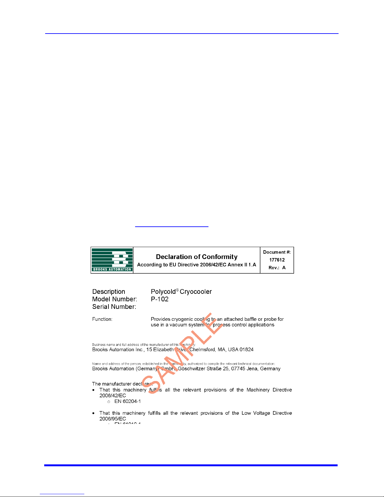
A Declaration of Conformity was sent with your Polycold Cryocooler. If you no longer have this
document, please contact [email protected]. Below is a sample of a Declaration of
Conformity.
Page 6
Limited Warranty
Page 7

Limitations
This product is intended for use by industrial customers and should be serviced only by Brooks or
Brooks trained representatives. The service manuals and related materials are provided in English at
no charge and are intended for use by experienced technicians. It is the responsibility of the user to
obtain and assure the accuracy of any needed translations of manuals. If you require assistance
please contact Brooks service department. Contact information can be found at www.brooks.com.
Page 8

1. Introduction
System Summary User Manual
1. Introduction
System Summary
The Polcold® P-102 Portable Cryocooler provides compact, portable, and easy-to use alternatives to
liquid nitrogen used in small vacuum systems. These cryogenerators use refrigerants in a closed loop
system. The refrigerants are:
l Safe
l Non-flammable
l Non-toxic
l HCFC-free
This means there is no moving of heavy liquid nitrogen dewars. Also, there is no running out of
cryogen causing downtime.
Installation is quick and easy. Either a cold probe is inserted into a housing or a chevron baffle is
installed between a diffusion pump and a high vacuum valve. The cold probes and chevron baffles are
referred to as cryosurfaces. These are part of the refrigerant line. Removing them causes a loss of
refrigerant.
Cold trapping applications include:
l Helium mass spectrometer leakdetectors
l Chevron baffles for diffusion pumps up to 6 inches (160 mm) in diameter
l Vapor trapping cold probes that protect mechanical pumps on smallvacuum systems.
Basic Principles of Operating for the Polycold Refrigeration Cycle
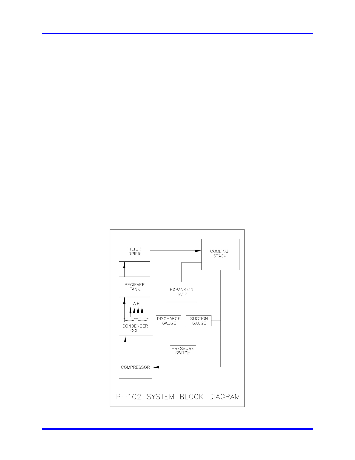
This cooling process is an auto cascade refrigeration system. A patented mixture of non-flammable
and safe CFC-free and HCFC-free refrigerants is compressed and circulated by a compressor. In a
simplified version, the Polycold refrigeration cycle comprises:
1. Compressing a mixture of refrigerants
2. Partially condensing the higher boiling fractions in an air-cooled condenser
1-1 Brooks Automation
Page 9
1. Introduction
User Manual Basic Principles of Operating for the Polycold Refrigeration Cycle
3. Separating and throttling the liquid condensate produces cooling that condenses the remaining
vapors in a special heat exchanger. In the process of providing cooling in the Cryocooler, this
mixture is partially evaporated.
4. Throttling this latter condensate and feeding the cryocoil to produce cooling at very low
temperatures
5. Passing the refrigerant leaving the cooling coil back through the heat exchanger to the compressor.
Operating pressures and compressor temperatures are similar to those in air-conditioning systems.
The compressor lubricating oil circulates with the discharge vapors. The oil promptly returns to the
compressor without reaching the very low temperature portions of the system. This eliminates the
common problems of oil plugging in evaporators and expansion devices too often seen in low
temperature systems.
The mixed refrigerant charge is hermetically sealed into the system. Normally neither the refrigerant
nor the compressor lubricating oil requires replacement or recharging.
In this unit, there is a series of intermediate special heat exchangers called cascade condensers.
These are located between the air-cooled condenser and the final cooling coil (cold probe). There are
multiple stages of partial condensation, phase separation, condensate throttling, and intermediate
cooling. In addition, the system has a suction-side refrigerant vapor expansion tank and a dischargeside receive tank to limit start-up discharge pressures.
Accelerating Innovation 1-2
Page 10
1. Introduction
System Components User Manual
System Components
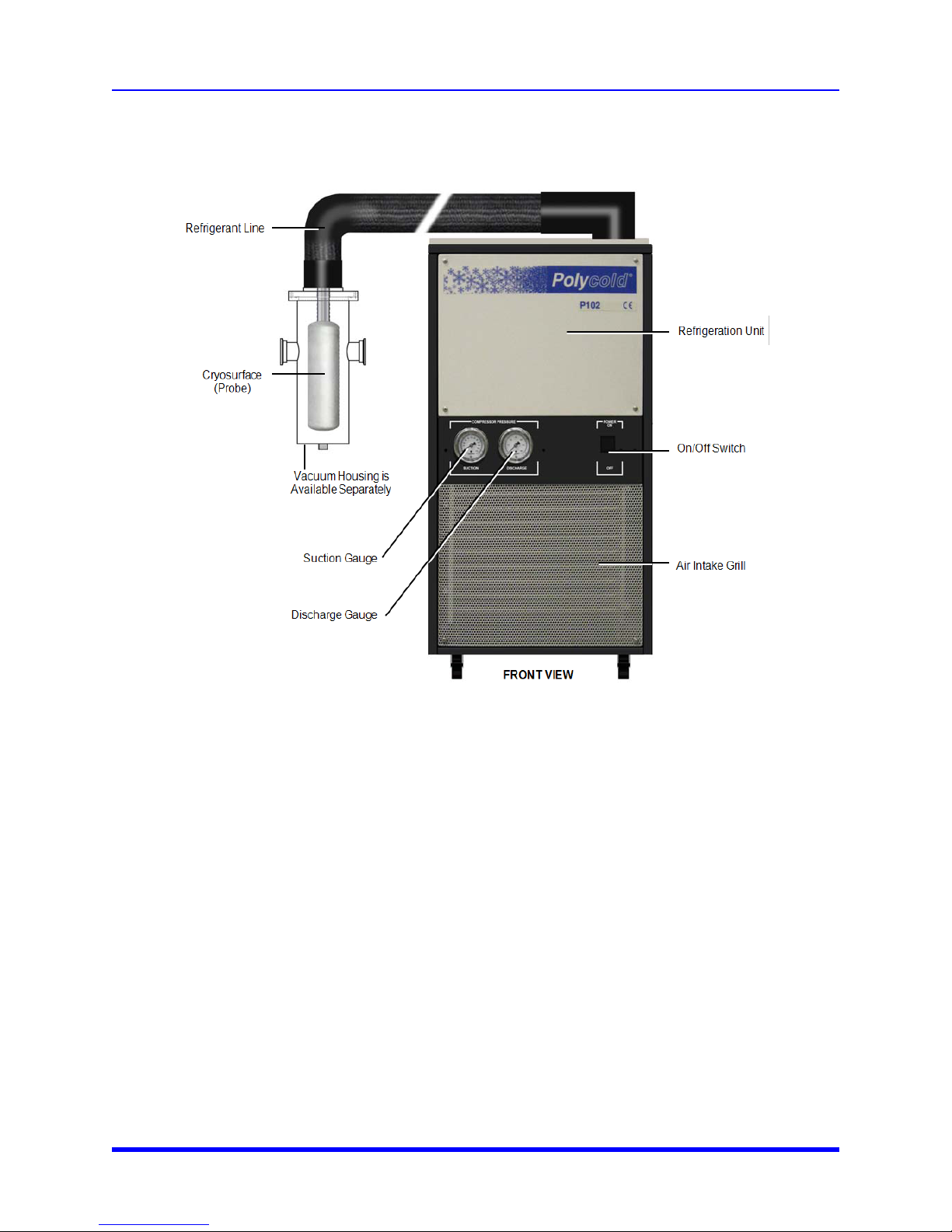
Figure 1-1: P-102 Croyocooler
Specifications of the System
Physical Specifications
NOTE: All specifications are for the standard product configuration, specifications can vary for
customized configurations.
1-3 Brooks Automation
Page 11
1. Introduction
User Manual Specifications of the System
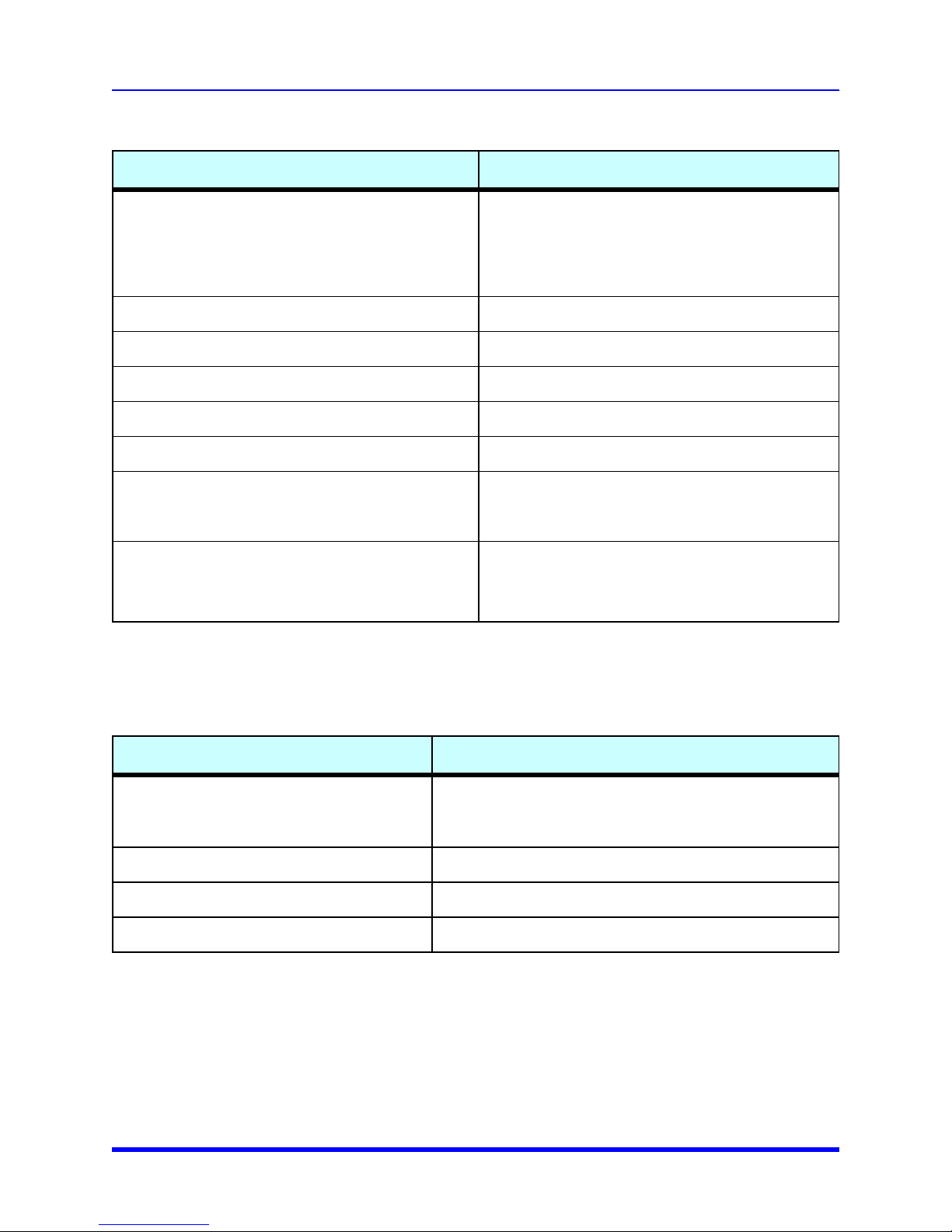
Table 1-1: Physical Specifications
Physical Property Value
Dimensions:
Width
Depth
Height
(From floor, including casters, to top of frame)
Weight, with lines: 82 Kg (180 lb)
Flex line length: 1778/1752.6 mm (70/69 in) (Standard 5 foot flex line)
Cooling: Forced air
Temperature at Heat Load: -135° C with no load. And -110° C with 120W load
Initial cool down Time: 1.5 hr
445 mm (17.5 inches)
521 mm (20.5 inches)
845 mm (33.25 inches)
Baffles:
Chevron Baffles, Opaque, low-profile, spool piece
style
Cold Probes
l 4-inch cold bath, nominal 4-inch chevron baffle
l 6-inch cold bath, nominal 6-inch chevron baffle
l Trap housing for mechanical pump traps
l Cold probe, stainlesssteel, “Easy Clean”
l Cold probe, nickelplated copper with coil on
exterior of mandrel
Operating Specifications
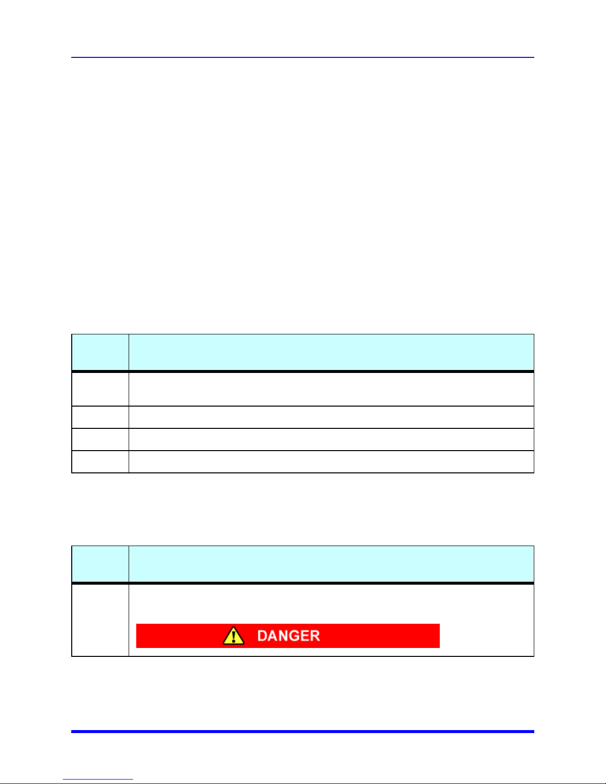
Table 1-2: Operation Specifications
Property Specification
Room temperature to -110° C (-166° F) in about 45 minutes
Ramp Time to Temperature: (No applied load)
Room temperature to -125° C (-193° F) in about 80 minutes
Operating Temperature Ambient room temperature of 15 - 30° C (59 - 86° F)
50Hz Operation Temperature will be approximately 5°C Warmer
Noise (maximum) 69 db(A) at 1m from the unit
Moving the Product
The Polycold Cryocooler P-102 rolls across smooth floors on four casters. Be sure there are no
objects in the path as you roll the unit. Rolling across objects or wiring creates a tip hazard. Rolling up
or down ramps also creates a tip hazard.
Accelerating Innovation 1-4
Page 12
1. Introduction
Safety Alerts, Equipment Alerts, and Add Info Formats User Manual
The casters have no locking device. Use proper care when moving the P-102. Position the Cryocooler
in a way it can not accidently be moved to an improper location.
Safety Alerts, Equipment Alerts, and Add Info Formats
This manual and the Polycold Portable Cryocooler P-102 uses the following conventions for notifying
the user about personal or equipment safety. This chapter shows the alerts used on the equipment
and the locations of the alerts on the equipment.
Alert Signal Word Definition
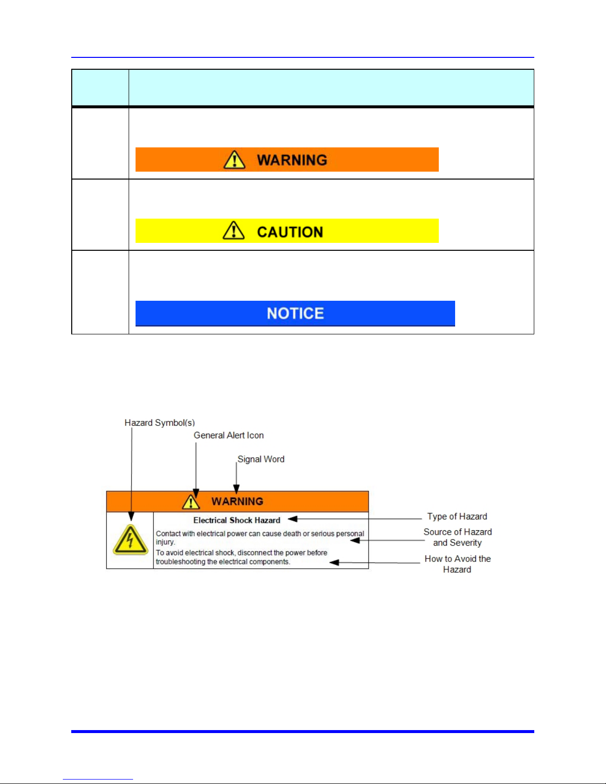
The following are definition of the four levels of alerts as defined by ANSI and SEMI. The most serious
is listed first. DANGER, WARNING, and CAUTION are defined by the level of personal injury.
NOTICE only applies to possible equipment or material damage.
Table 1-3: Signal Word Definitions
Signal
Word
DANGER
WARNING Indicates a hazardous situation which, if not avoided, could result in death or serious injury.
CAUTION Indicates a hazardous situation which, if not avoided, may result in minor or moderate injury.
NOTICE Indicates a situation which, if not avoided, could result in property damage.
Indicates a hazardous situation which, if not avoided, will result in death or serious injury. This
signal word is to be limited to the most extreme situations.
Definition
Alert Colors
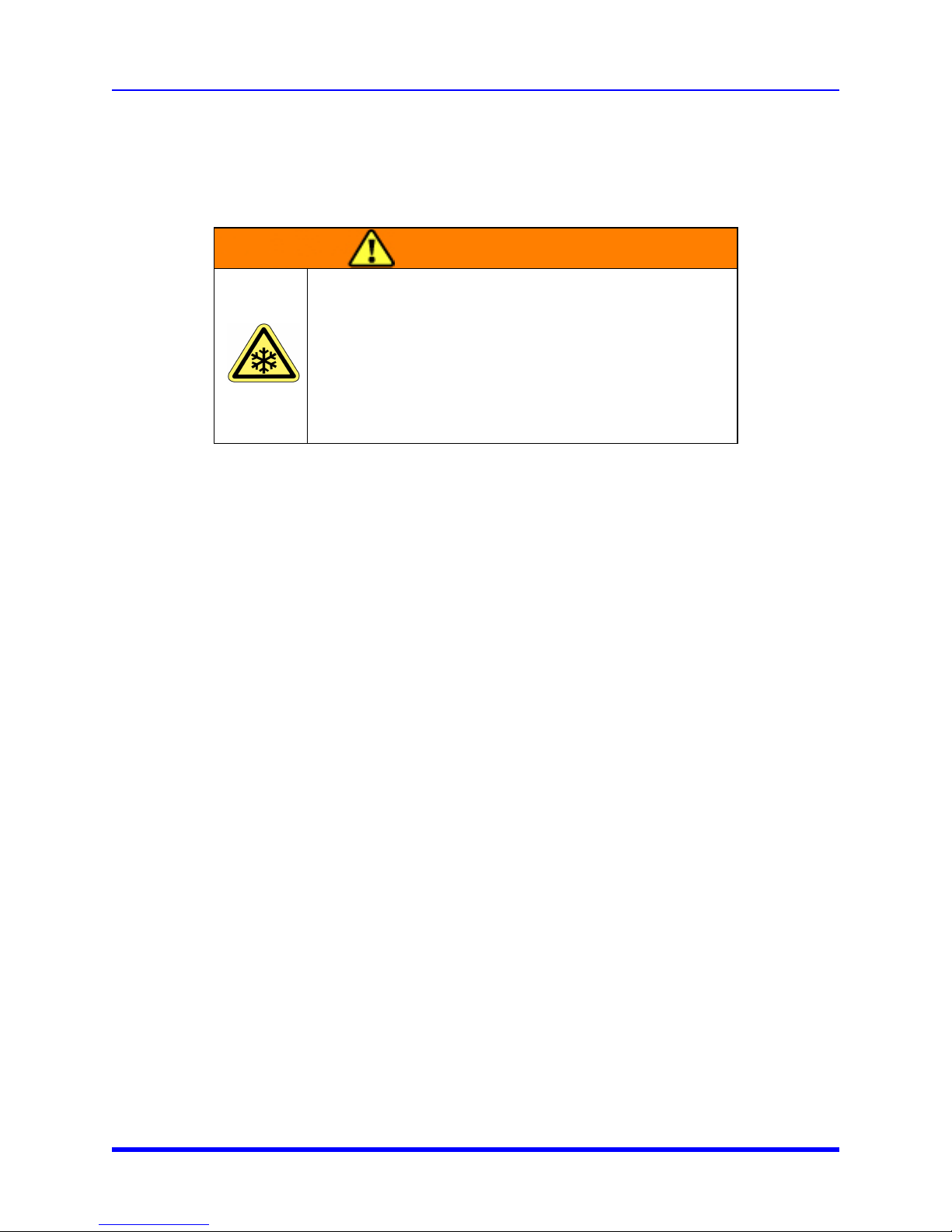
Table 1-4: Colors of Signal Word Panels
Signal
Word
DANGER
Background: Red
Signal Word: White
General Icon in the Signal Word Frame: Yellow with Black frame and exclamation point
Color of Signal Word Panels and Backgrounds
1-5 Brooks Automation
Page 13
1. Introduction
User Manual Safety Alerts, Equipment Alerts, and Add Info Formats
Signal
Word
Signal Word: Black
Background: Orange
WARNING
CAUTION
NOTICE
General Icon in the Signal Word Frame: Yellow with Black frame and exclamation point
Signal Word: Black
Background: Yellow
General Icon in the Signal Word Frame: Yellow with Black frame and exclamation point
Signal Word: White
Background: Blue
The signal word area of the alert does not contain an icon. The text area may include icons that
are not intended for personal safety.
Alert Example
Color of Signal Word Panels and Backgrounds
The following is an example of a WARNING alert.
Use of Notes
Notes are used throughout the manual to make the user is aware of additional information or to explain
important information. Information in notes is not related to human or equipment safety. A note does
not use icons. The following is an example of a Note.
Accelerating Innovation 1-6
Page 14

1. Introduction
Safety and Equipment Considerations User Manual
NOTE: Save all shipping materials for possible future use. If you return the P-102 to Polycold
Systems for service or ship it to another location, the original shipping crate must be used.
Safety and Equipment Considerations
These the following are basic guidelines. If the facility additional safety guidelines, follow those as
well. Also follow all national and international safety codes that apply.
Equipment Guidelines
The following guidelines aid in the use and service of the Polycold Cryocooler P-102.
l Brooks Automation Technical Support issues a Technical Support Bulletin (TSB) to notify the owners of
record of any field retrofits.
l Contact Brooks Automation Customer Support for information about repair and maintenance service
policies, both during the production of the product and after production is discontinued.
l Any user caused damage during the assembly of the product into their equipment is the user’s respons-
ibility.
l Polycold System’s responsibility for work performed by Polycold/Brooks authorized technicians or for
equipment transported or resold by the owner of record is determined on a case-by-case basis by Brooks
Automation Technical Support.
l Any parts being returned to Polycold are to be packaged according to the instructions provided with the
replacement part. Packing instructions for shipping the Cryocooler P-102 are provided.
l Only qualified, properly trained persons should perform any procedures on the product. Damage that res-
ults from not properly performing a procedure or not following cautions and notices is not covered under
warranty or service agreements.
Personnel Safety Guidelines
The Brooks Automation, Inc. Polycold Systems P-102 may provide several direct safety hazards to
personnel if not properly installed or operated.
l Persons operating the product should be properly trained.
l Possible injury can result from the automatic operation of the product if the covers are removed.
l Wear the following safety equipment according to the manufacturer’s instructions before you to install or
service the P-102:
l Eye protection
l Gloves
l Observe the facility guidelines pertaining to loose clothing while working around or operating the P-102.
l Read and understand the Material Safety Data Sheets (MSDS) for each chemical used with the product.
These individual sheets are provided in "Material Safety Sheets" on page I.
l It may be recommended that the use of hazardous materials, such as cleaning fluids, be used during
routine maintenance procedures. Read and understand the facility’s MSDS (provided by the manufacturer) for each substance.
1-7 Brooks Automation
Page 15
1. Introduction
User Manual Safety and Equipment Considerations
l Ensure the product has been properly decontaminated before performing any service. Following the facil-
ities’ decontamination procedures. Follow all facility and regulatory procedures for the disposal of any
hazardous materials.
l Ergonomic hazards may exist when moving the P-102.
l Know the locations of Hazardous points on the P-102.
WARNING
THERMALHAZARD
Do not come in contact with the probe or baffles while they are
cold. Frost bite or other contact could cause personal injury.
Wait at least 90 minutes after the P-102 is turned off before
allowing the probe or baffles to touch your body. The probe is to
be at +10° C (50° F) before any person touches the probe.
l The probe is to be at +10° C (50° F) before any person touches the probe. When removing the probe from
the vacuum housing protect yourself from contact with the cold probe when handling.
l Allow the cold probe to warm up for at least 90 minutes by which time it should be at +10° C (50° F). If
signs of frost are still evidenced, then wait until all signs of frost are gone. If you must handle the probe
before then, use appropriate personal protective equipment needed to protect against frostbite hazard.
Equipment Safety Guidelines
The following safety considerations aid in the placement and use of the Cryocooler. down the
equipment during installation as needed.
l The product is not provided with an Emergency Off (EMO) circuit. The user is accountable for the EMO cir-
cuit.
l Do not place the product’s electrical connection or cold head line where they could cause a trip hazard.
l Do not place the product in a location where it may be subject to physical damage.
l Ensure that all power connections to the product are properly grounded.
l Ensure that the product receives proper air flow for cooling.
l Do not remove safety labels or equipment identification labels.
l Turn OFF power before inserting or removing power cables.
l Be aware of the hazardous points of the product as described in this chapter.
l Use of the P-102 for any purpose other than as a cryocooler is not recommended and may cause dam-
age to the product or the equipment to which it is connected.
l Always operate the Cryocooler P-102 with the protective covers in place.
l Do not install or operate the product if it has been dropped, damaged, or is malfunctioning.
l Do not immerse cables or connectors in liquid.
l Keep cables and connectors away from heated surfaces.
l Do not modify the connectors or ports.
Accelerating Innovation 1-8
Page 16
1. Introduction
Safety Labels and Safety Label Identification User Manual
Safety Labels and Safety Label Identification
Labels
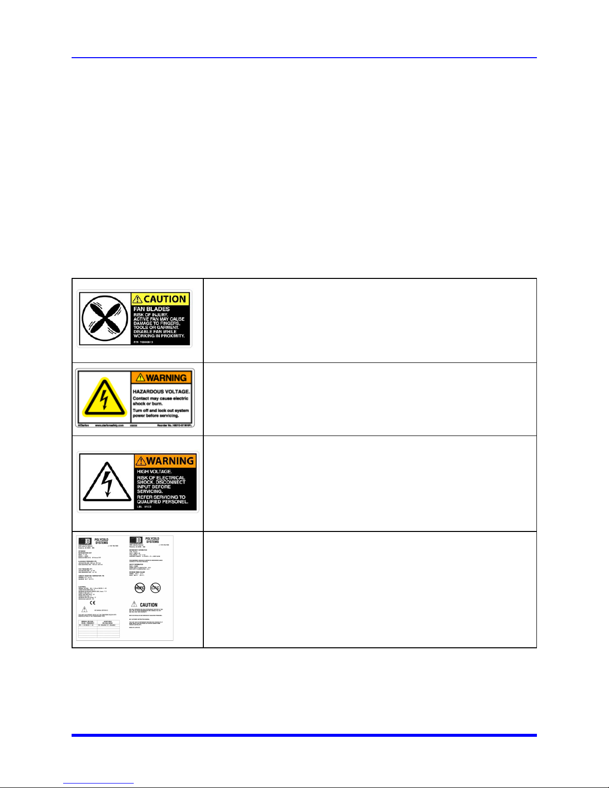
Safety labels and identification labels are placed on the Cryocooler P-102. These labels provide
information for operators and service personnel to identify hazards. Some labels inform the user about
the product. This section describes each label and identifies its location. Safety labels give
instructions on how to avoid the hazard.
Label Identification and Location
Table 1-5 lists the labels that are affixed to the P-102. These labels alert personnel to hazards on or
within the product. They also provide information about the product.
Hazard: Mechanical Motion
Qty: 2
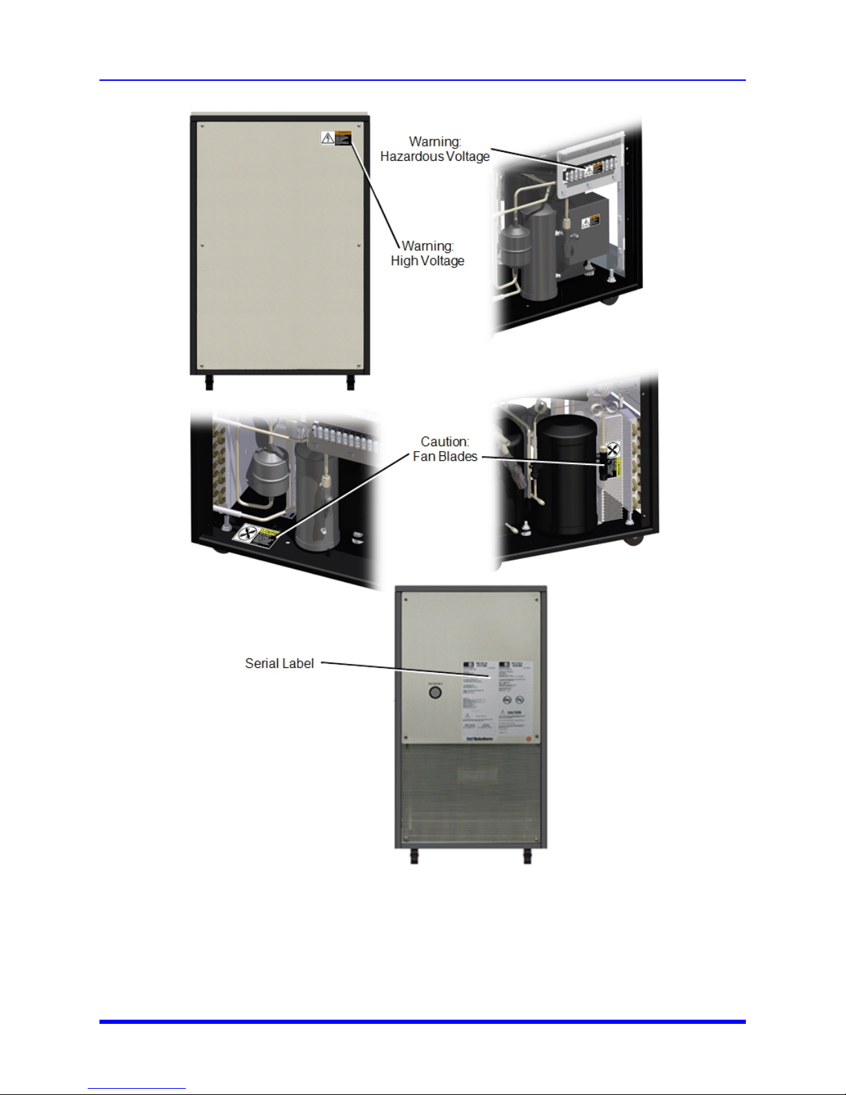
Location: One on the fan shroud, half way up the side. One on the base plate on
the side of the fan that is not shrouded.
Hazard Type: CAUTION
Possible Injuries: Damage to fingers
How to avoid the hazard: Keep hands away from the fan.
Hazard: Electrical Hazardous Voltage
Qty: 1
Location: Panel in front of where the terminal block mounts inisde the P-102
Hazard Type: WARNING
Possible Injuries: Electrical Shock or Burn
How to avoid the hazard: Lockout/Tagout before servicing
Hazard Type: Electrical High Voltage
Qty: 2
Location: One on the compressor electrical box cover. One on the upper corner
of the right side cover within which the terminal strip is mounted.
Hazard Type: WARNING
Possible Injuries: Electrical Shock or Burn
How to avoid the hazard: Lockout/Tagout before Servicing. Servicing by qualified
personnel
Serial Label
Qty: 1
Location: Lower right corner of upper real panel.
Hazard Type: N/A
Possible Injuries: N/A
How to avoid the hazard: N/A
Figure 1-2 shows the location of each label. To replace a lost or damaged label call Brooks Automation
Technical Support.
1-9 Brooks Automation
Page 17
1. Introduction
User Manual Safety Labels and Safety Label Identification
Accelerating Innovation 1-10
Figure 1-2: Locations of Labels on the P-102
Page 18
1. Introduction
Mechanical Hazards User Manual
Mechanical Hazards
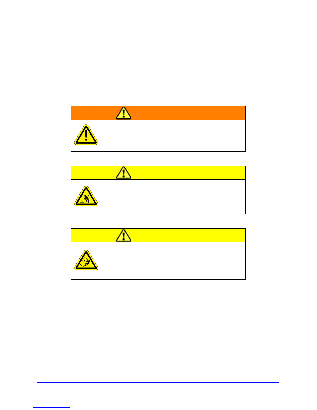
The Polycold P-102 is a mechanical device. The P-102 contains a fan to air cool the condenser. Do
not operate the P-102 without the protective covers.
NOTE: Only persons with the proper training are to service or operate the product.
Use Safety glasses and gloves when working on or near the P-102.
WARNING
Whenever power is applied the fan automatically turns on.
There are no obstruction sensors and movement could result in
personal injury.
Do not operate the P-102 without the protective covers in place.
CAUTION
Heavy Object Hazard
The Product weighs 82 kg (180 lb). Do not attempt to lift the
P-102 without a forklift. Roll the P-102 across smooth floors.
CAUTION
Tip Hazard
Tip hazard exists when moving the P-102 up or down a ramp.
Be sure to prevent the P-102 from tipping when using a ramp.
1-11 Brooks Automation
Page 19
1. Introduction
User Manual Electrical Hazards
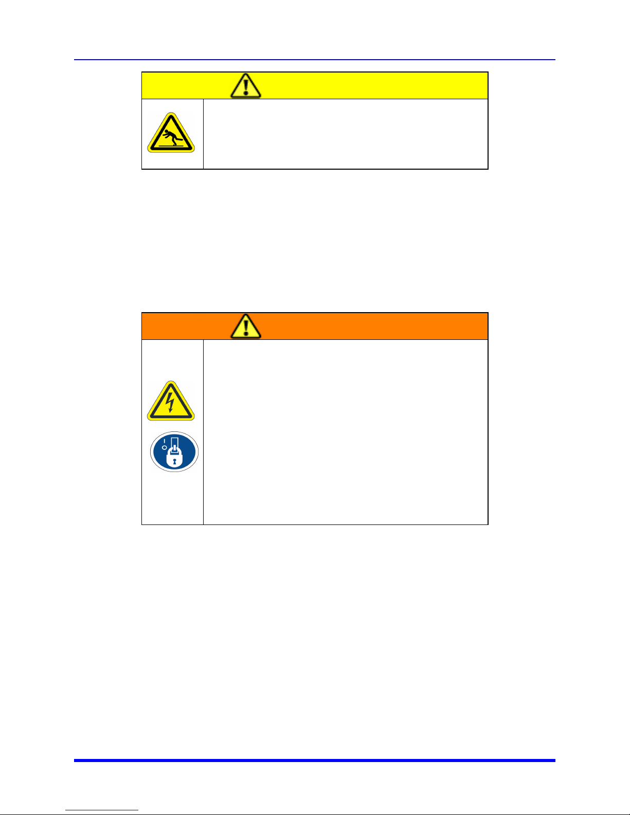
CAUTION
Trip Hazard
Trip hazard exists if the power cord is not routed to in a way to
cause a trip hazard.
Route the cord in an area where there is no travel.
Electrical Hazards
The Brooks Automation, Inc., Polycold Systems P-102 is a high voltage device. At maximum load the
product is capable of drawing close to 11.5 Amps at 200 - 230 VAC VDC. Maximum power
consumption @ rated load for this product is 1620 watts. The minimum overcurrent ratings for
disconnects requires a user installed 230 VAC, 20 A, minimum SCCR rating of 10 KIAC.
The proper precautions for operating and servicing electrical equipment must be observed.
WARNING
Electrical Hazard
The P-102 is a high voltage device. Turn off power and perform
Lockout/Tagout before servicing.
Improper electrical connection and connection to an improper
electrical supply can cause electrical hazards. Improper
handling of the power source or connecting devices can cause
electrical shock or burns. These can result in serious injury or
death or cause an equipment fire and damage to the
equipment.
Always provide the product with the proper electrical code
compliant connections.
Environmental Hazards
Noise
The Brooks Automation Product provides no direct noise hazard.
Vibration
The Brooks Automation Product provides no direct vibration hazard. Any vibrations produced are
minimal and cause no hazardous conditions.
Accelerating Innovation 1-12
Page 20
1. Introduction
Recycling and Disposal Information User Manual
Recycling and Disposal Information
The Brooks Automation Product contains refrigerant that may requires special handling for disposal or
recycling.
Refrigerant
A qualified refrigeration technician is needed to remove the refrigerant from the P-102. Follow all
facility and regulatory procedures for the disposal of hazardous materials.
Disposal of the P-102 When Decommissioning
Follow all facility and regulatory procedures for the disposal of hazardous materials.
WARNING
CHEMICALHAZARD
Whenever any cleaning fluid is used during service of the P-102,
the facility’s environmental procedures must be followed regarding
the storage, handling, and disposal of that fluid.
Thermal Hazard
The condenser and compressor inside the P-102 become hot during operation. Wait 90 minutes after
you perform Lockout/Tagout according to the facility procedures before removing any covers.
WARNING
THERMALHAZARD (hot)
Hot surfaces can cause burns and personal injury.
Do not operate the P-102 without all covers in place. Wait 90
minutes after performing Lockout/Tagout according to the
facilities procedure before removing any cover.
The probe is to be at +10° C (50° F) before any person touches the probe. When removing the probe
from the vacuum housing protect yourself from contact with the cold probe when handling.
Allow the cold probe to warm up for at least 90 minutes by which time it should be at +10° C (50° F). If
signs of frost are still evidenced, then wait until all signs of frost are gone. If you must handle the probe
before then, use appropriate personal protective equipment needed to protect against frostbite hazard.
1-13 Brooks Automation
Page 21
1. Introduction
User Manual Thermal Hazard
WARNING
THERMALHAZARD (cold)
Do not come in contact with the probe or baffles while they are
cold. Frost bite or other contact could cause personal injury.
Wait at least 90 minutes after the P-102 is turned off before
allowing the probe or baffles to touch your body.
Reference Document:
ISO 13732-3, Ergonomics of the thermal environment - Methods for the assessment of
human responses to contact with surfaces; Part 3: Cold Surfaces
Accelerating Innovation 1-14
Page 22
2. Installation
Installation Requirements User Manual
2. Installation
Installation Requirements
The following information contains information you need for installation of the P-102.
Power Specifications
The following table includes electrical specification for the P-102.
Table 2-1: Electrical Specifications
Electrical Properties Specifications
Voltage/Frequency/Phase
(±10%)
Inrush Current 41 Amps (locked rotor amps)
Maximum Continuous
Current
Rated Load Amps 7.5 Amps
Overvoltage Category Category II
Disconnect Device
200 VAC @ 50 Hz - Single Phase
208-230 VAC @60 Hz - Single Phase
11.5 Amps Maximum
The disconnect device is customer supplied. It should be rated for minimum 10
KAIC. The P-102 is not provided with a circuit breaker or a disconnect device.
Site Requirements
The following table lists Site Specifications.
2-15 Brooks Automation
Page 23
2. Installation
User Manual Installation Requirements
Table 2-2: Environmental Specifications
Environmental Factors Specifications
Temperature:
Ambient Air During Operation
Shipping
Storage
50Hz Operation
Relative Humidity 20 – 80%, non-condensing relative humidity
Lighting
Transport The P-102 must remain in a vertical position.
Install Location
Service Access
Ground Clearance 1 7/8 inches
15 – 30° C (59 – 86° F)
-20 – +49° (-4 – +120° F)
A room temperature of 4 – 49° C (40 – 120° F), non condensing
Temperature will be approximately 5°C Warmer.
Standard lighting is sufficient for proper operation. Maintenance may require
a service lamp or flashlight.
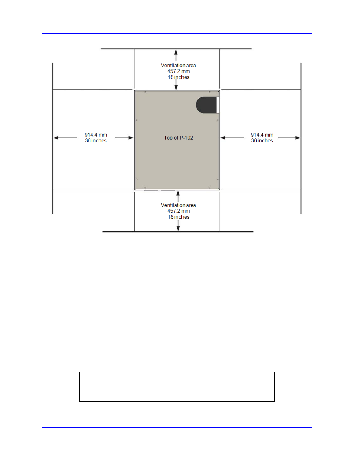
Be sure to allow 18 inches in front of and to the rear of the P-102.
Well ventilated area greater than 2200 ft
Above ground
The P-102 requires adequate space for service access and for proper
ventilation. Typical service space required is shown in Figure 2-1 .
Allow 36 inches to the left and right sides of the P-102 for service areas.
3
Rolling Provision Four casters
Lifting Provision Use a fork lift
None. Determine if the P-102 is being used in an earthquake prone area. If
Hold-Down Provision
so, the customer needs to provide tie-downs to prevent the P-102 from
moving during an earthquake.
NOTE: The facility is responsible ensuring the Cryocooler P-102 installation complies with the local
electric codes.
Service and Exclusion Zones
Place the P-102 so that the area indicated in Figure 2-1 is available for service and ventilation.
Accelerating Innovation 2-16
Page 24
2. Installation
Unpacking and Inspection User Manual
Figure 2-1: Service and Exclusion Zones
Unpacking and Inspection
Unpack the crate carefully. Inspect and verify its contents against the shipping documents. Report
any damage immediately to the shipper and to Polycold Systems, Inc.
One set of shipping documents are attached to the outside of the main shipping crate for easy access.
An additional set of the same documents are attached to the equipment inside the shipping crate.
NOTE: Shipping Balance Pressure Range: 125-145 psi at 21°C (70°F) or above
Unpacking and Moving Instructions
Fork Lift
Tools and Materials
High vacuum lubricant – must have an appropriate low
vapor pressure for use with an o-ring seal
2-17 Brooks Automation
Page 25
2. Installation
User Manual Unpacking and Moving Instructions
Unpacking the P-102
1. Upon receiving the crate, inspect the indicators for disturbance. Also, visually verify each crate is
not damaged. Inform the freight carrier and Polycold Technical Support of any inspection
discrepancy.
2. Remove the cover of each shipping crate. Inspect, and verify the contents against the shipping
documents. Do not remove any protective wrapping.
NOTE: Save all shipping materials for possible future use if the P-102 is returned to Brooks
Automation, Inc./Polycold Systems or shipped to another location. If the original crates have become
lost or damaged, contact Polycold Systems for replacements. Refer to "Material Safety Sheets" on
page I.
3. Move the product to its final location.
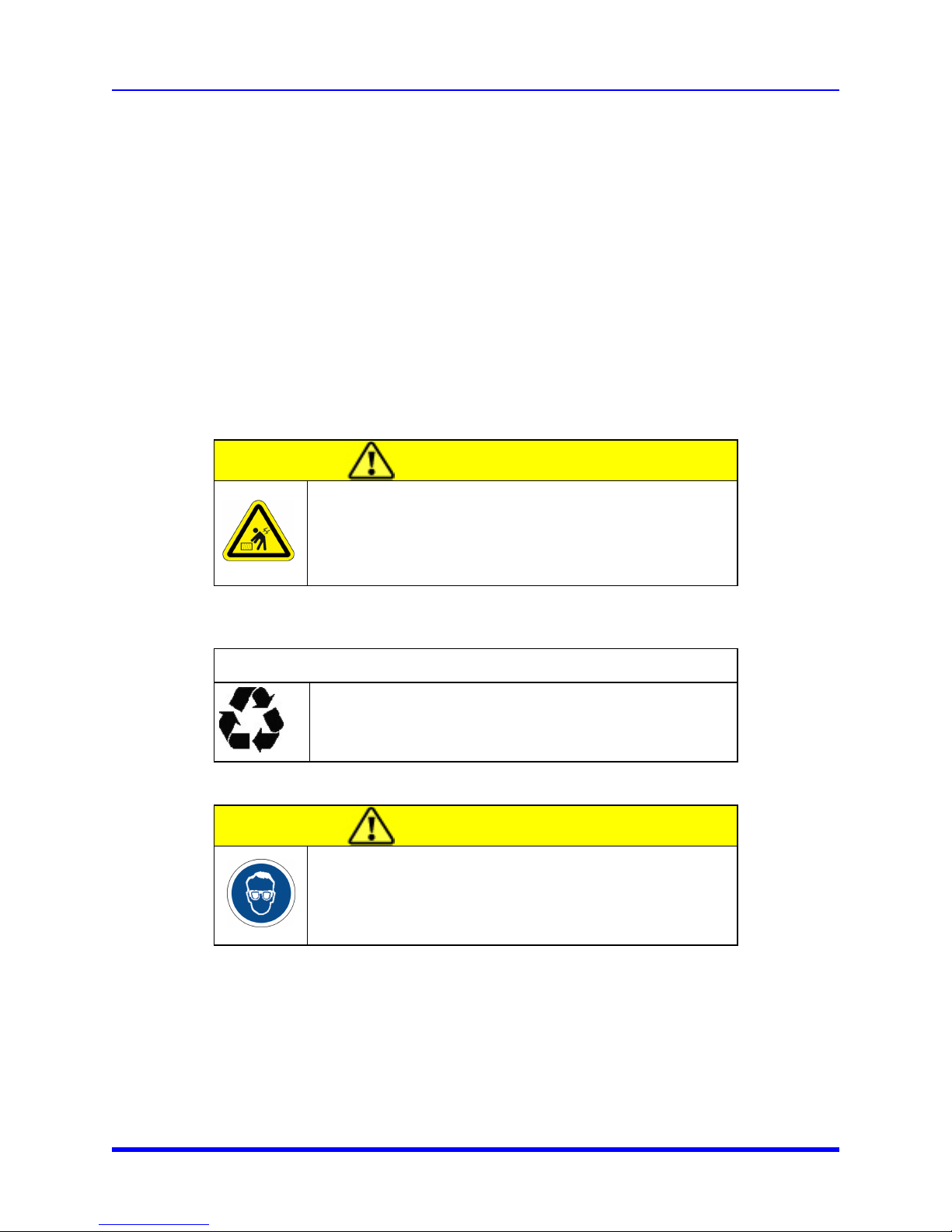
CAUTION
Heavy Object Hazard
The Product weighs 82 kg (180 lb).Failure to take the proper
precautions before moving it could result in personal injury.
4. Remove the bag from the Product and carefully inspect the product for signs of damage that may
have occurred during shipping.
RECYCLE
Recycle all packaging materials.
CAUTION
Safety glasses and gloves are to be worn at all times when
installing the product.
5. Inspect all vacuum sealing surfaces where the cold probe or cryobaffle is to be used. The surfaces
must be clean and free from scratches or other imperfections that might result in vacuum leaks.
Protect these surfaces at all times.
6. Remove any contaminants by wiping them with a clean cloth moistened with alcohol.
Accelerating Innovation 2-18
Page 26
2. Installation
Starting Up the P-102 User Manual
Moving the P-102
1. Use a lift to lift the P-102 off the pallet and place it on the floor.
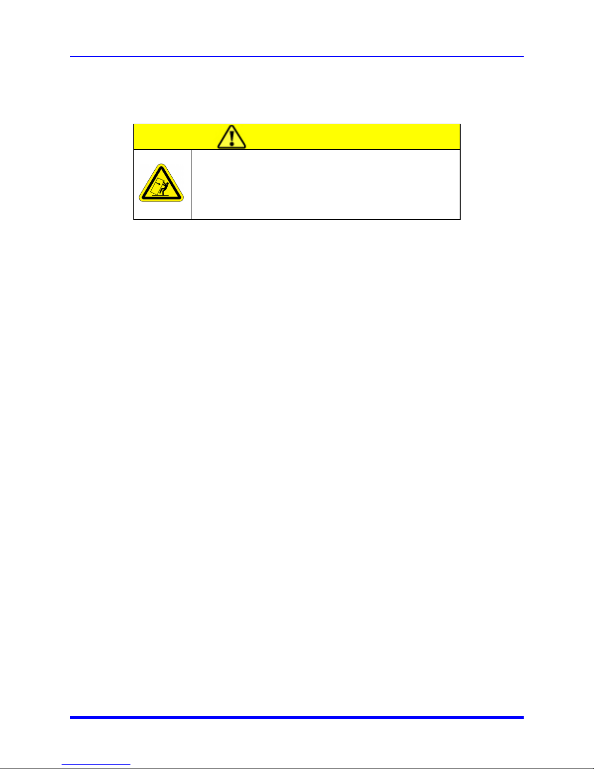
CAUTION
Tip Hazard
Tip hazard exists when moving the P-102 up or down a ramp.
Be sure to prevent the P-102 from tipping when using a ramp.
2. Roll the P-102 carefully to where the tool is to be installed. Be sure the floor is smooth and there is
no tip hazard. Roll the P-102 very carefully if it must roll up or down a ramp. This may cause a tip
hazard.
3. The system may be operating continuously. It should be turned off any time the fore- or roughing
pump(s) are to be turned off.
Starting Up the P-102
1. Start the unit by turning on the front panel switch.
l You can hear the compressor and condenser fans start running.
l The Power light on the front panel lights.
l Within about 5-10 minutes, cooling begins in the cold probe.
If the compressor turns off during initial start up, turn the switch off for 5-10 minutes, then turn the
switch on again to restart the P-102.
Do not operate the unit for more than 15 minutes. This causes moisture to accumulate on the cold
probe.
2. Turn off the unit.
3. Warm the cold probe.
4. Dry the cold probe.
5. Inspect all vacuum sealing surfaces where the cold probe or cryobaffle is to be used. The surfaces
must be clean and free from scratches or other imperfections that might result in vacuum leaks.
Protect these surfaces at all times.
6. Remove any contaminants by wiping them with a clean cloth moistened with alcohol.
2-19 Brooks Automation
Page 27

2. Installation
User Manual Starting Up the P-102
7. Insert the cold probe in its the cold trap.
8. Make certain there are no sharp bends or strains on the flexible insulated line that leads to the cold
probe.
9. Check the vacuum chamber where the cryobaffle is installed for leaks between the vacuum
chamber and cryobaffle.
10. Rough the vacuum system down.
11. Turn on the P-102.
12. Be careful not to bend the insulated flex line much after the unit has chilled down the probe and
line. This can lead to cracks in the insulation.
NOTE: The system may be operating continuously. It should be turned off any time the fore- or
roughing pump(s) are to be turned off.
Accelerating Innovation 2-20
Page 28
3. Operation
External Controls and Indicators User Manual
3. Operation
This chapter describes how to operate the P-102.
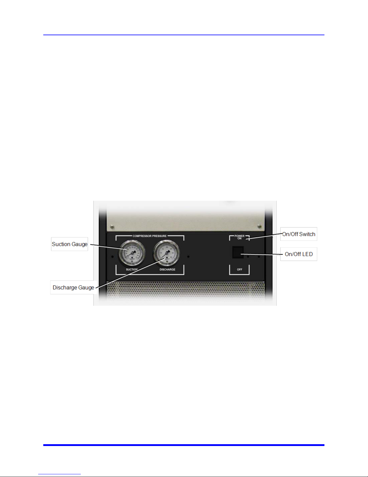
External Controls and Indicators
This section provides a description of the P-102 controls and indicators.
3-21 Brooks Automation
Figure 3-1: External Controls and Indicators
Page 29
3. Operation
User Manual Powering Up the P-102
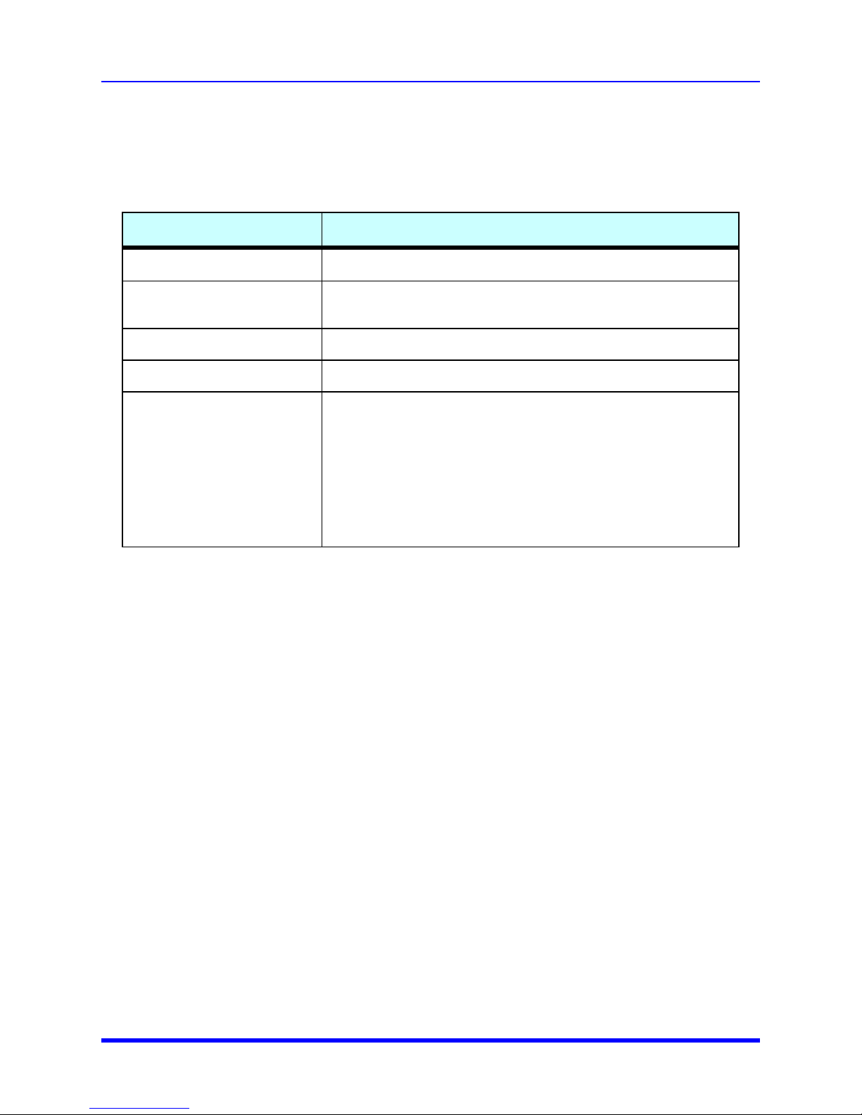
Table 3-1: External Controls and Indicators
Name Function
ON/OFF Switch Turns the P-102 power on and off
ON/OFF Switch LED
Turns on when the P-102 is turns on. Turns off when the power to the
P102 turns off
Suction Pressure Gauge Displays compressor’s suction pressure
Discharge Pressure Gauge Displays the Compressor’s discharge pressure
Type T thermocouples showing refrigerant temperatures feeding
and returning from the probe or baffle.
Feed and Return
Thermocouples
The Return thermocouple is shipped with a knot tied in the wire
while the Feed is shipped without this knot.
NOTE: Temperature meter should be set for Type-T
thermocouples.
Powering Up the P-102
1. Be sure the facilities power supply is correct for the P-102.
2. Plug the P-102 into the facilities power supply.
3. Turn on the power switch on the P-102.
You will observe the following:
l Audible noise from the fan
l Audible noise from the compressor
l Light on the power switch lights
4. Check the vacuum chamber where the cryobaffle is installed for leaks between the vacuum
chamber and cryobaffle.
Accelerating Innovation 3-22
Page 30

3. Operation
Defrosting the P-102 User Manual
The system may be operating continuously. It should be turned off any time the fore- or roughing pump
(s) are to be turned off.
Defrosting the P-102
If vacuum pump-down times or ultimate levels degrade, the cold probe may have accumulated enough
frost to affect performance.
1. Close the high vacuum valve and turn off the Cryocooler P-102 unit. The diffusion pump may be left
on or turned off at the user’s option.
2. Leave the fore-pump on to remove the evaporating moisture from the system.
Overnight defrosting is suggested. After defrosting, the P-102 unit can then be turned on again.
Restart the diffusion pump if it also was turned off. Many applications have low moisture loads and
continuous operation for months is possible without defrosting. Those systems with very heavy
moisture loads may require weekly defrosting.
Compressor and Condenser Fan Motors
The compressor and condenser fan motors are lifetime lubricated and do not require regular oiling.
Both the compressor and condenser have temperature switches that turn off either the fan or the
compressor if the motors for either begin to overheat.
Safe Shut Down
The following shut-down procedure is used to remove power from the Cryocooler P-102.
NOTICE
This shut-down procedure is used in the normal shut-down of the Product. This
procedure completely removes the power source and all other facilities to the
product.
1. Turn off the facility power to the P-102 or unplug it from the disconnect.
2. Turn off the ON/OFF switch. The light on the switch turns off.
3. Observe that the sounds of the fan, and condenser stop.
3-23 Brooks Automation
Page 31
3. Operation
User Manual Shutting the P-102 Down For Maintenance
Shutting the P-102 Down For Maintenance
Shutting the P-102 Down for Maintenance.
1. Be sure the P-102 is turned off. Be sure the power light to the P-102 turns off.
2. Remove the power plug from the facilities power source.
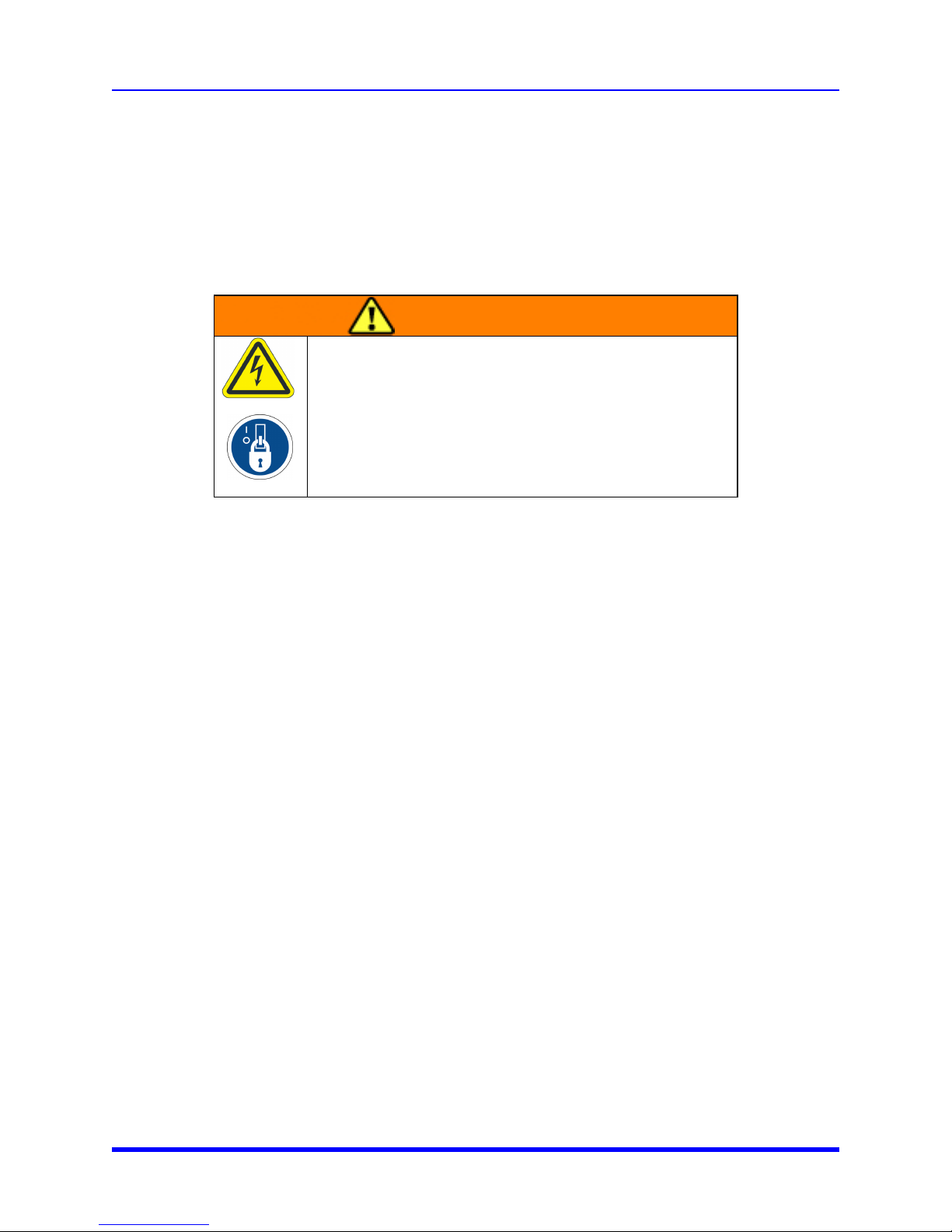
WARNING
Electrical Hazard
Electrical contact could cause death or serious injury.
Always perform Lockout/Tagout according to the facility’s policy
before working on the P-102.
3. Perform the Lockout/Tagout procedure according to the procedure at your facility.
NOTE: This procedure only shuts down power to the P-102. Any user equipment remains powered up.
Accelerating Innovation 3-24
Page 32
4. Preventive Maintenance
P-102 Maintenance User Manual
4. Preventive Maintenance
P-102 Maintenance
Follow the preventive maintenance procedures and schedule provided in this section. Performing
preventive maintenance extends the operating life of the product. Adjust the schedule you need
depending on where the Polycold Cryocooler is used.
WARNING
Mechanical hazards, electrical hazards, and shock hazards
exist on the P-102. The procedures in this chapter should only
be performed by qualified persons. Read and understand the
Safety section in Chapter 1 before performing any procedure.
Parts
Polycold can provide all parts required for Preventive Maintenance. For a list of these parts, contact
Brooks Automation Technical Support. Refer to Chapter 4: Parts and Service for contact information.
Preventive Maintenance Schedule and Procedures
Always perform Lockout/Tagout according to the facility procedure before removing any covers or
handling the cold probe or baffle. Wait 90 minutes after Lockout/Tagout is performed before opening
covers or handling the cold probe or baffle.
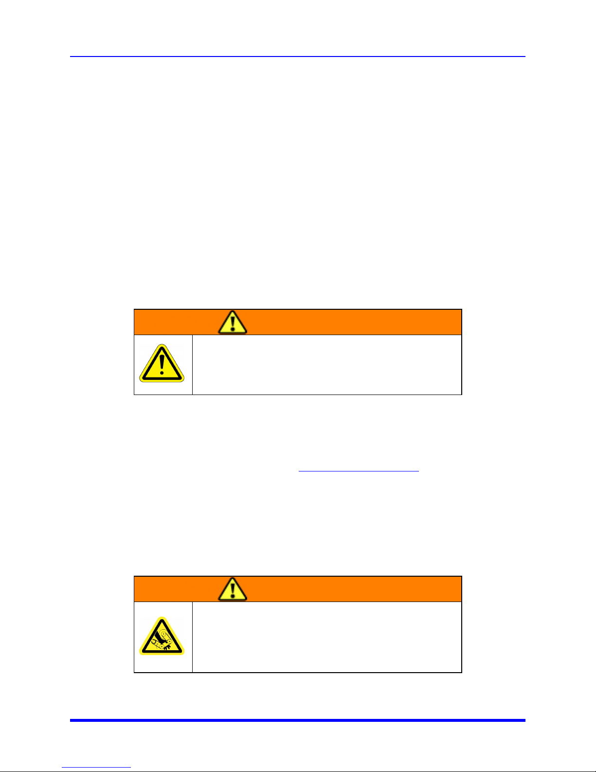
WARNING
4-25 Brooks Automation
The fan has no obstruction sensors and can cause serious
personal injury.
Do not operate the Product without the protective covers in
place.
Page 33
4. Preventive Maintenance
User Manual Cleaning the Air Cooled Condenser
WARNING
Electrical Hazard
The P-102 is a high voltage device. Turn off power and perform
Lockout/Tagout before servicing.
Improper handling of the power source or connecting devices
can cause electrical shock or burns. These can result in serious
injury or death or cause an equipment fire and damage to the
equipment.
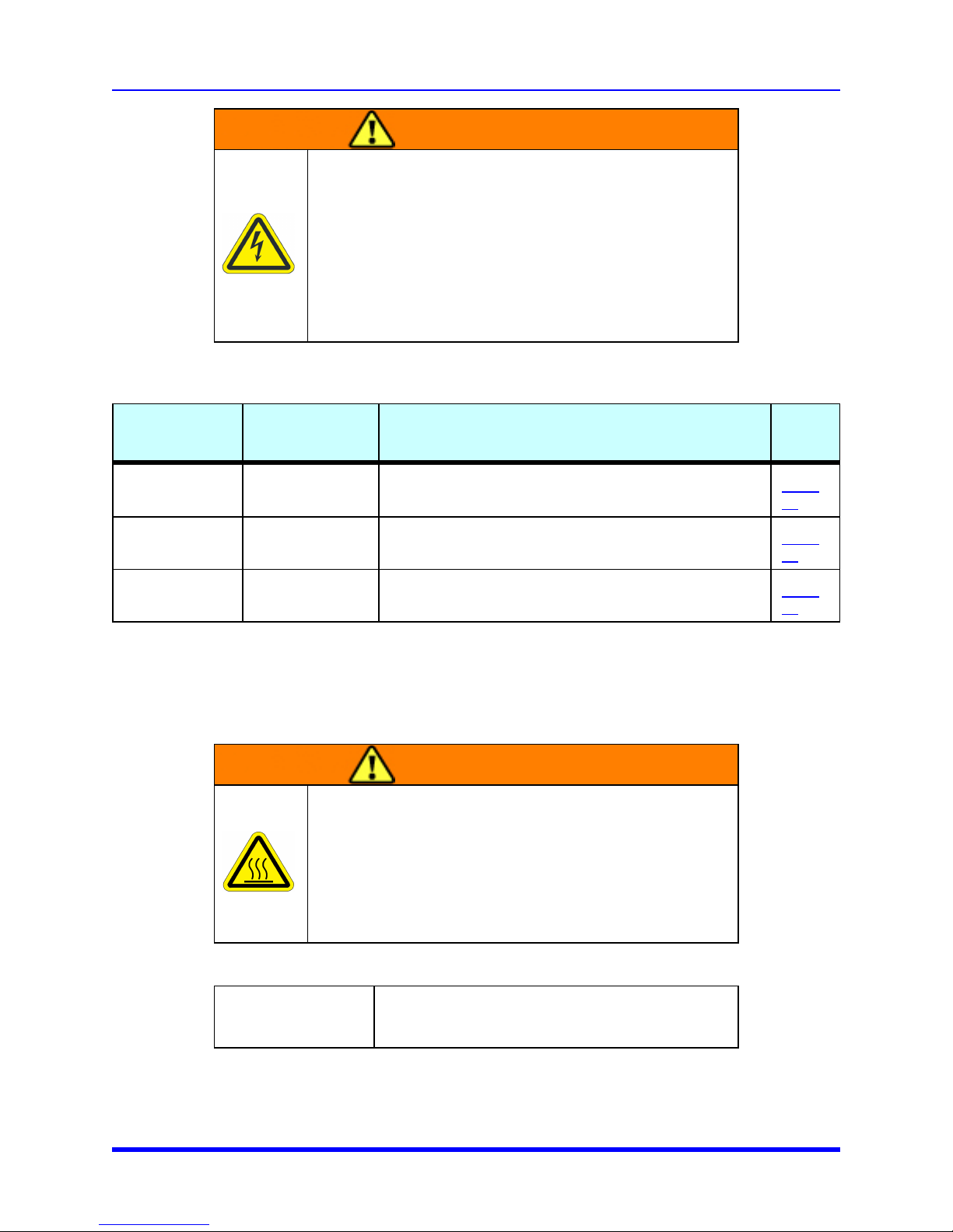
Table 4-1: Preventive Maintenance Schedule
Component
Air Cooled
Condenser
Air Intake Grill Cleaning
Cold Probe Cleaning
Maintenance
Action
Cleaning
Inspect weekly for the first month, then monthly until you
determine cleaning frequency
Dependent on how much dust and particles are in the
surrounding area
Clean after the cold probe is removed during servicing.
Some P-102 do not have cold probes.
Cleaning the Air Cooled Condenser
This procedure describes how to clean the air cooled condenser.
WARNING
THERMALHAZARD (hot)
Hot surfaces can cause burns and personal injury.
Frequency
Page
#
Page
26
Page
27
Page
28
Tools and Materials
Keep the air-cooled condenser clean enough for free air flow through it.
Accelerating Innovation 4-26
Do not operate the P-102 without all covers in place. Wait 90
minutes after performing Lockout/Tagout according to the
facilities procedure before removing any cover.
Phillips® screw driver
Brush, vacuum cleaner or compressed air blow-gun
Page 34
4. Preventive Maintenance
Cleaning the Air-intake Grill User Manual
1. Remove power from the system and allow 90 minutes before accessing the inside of the P-102.
2. Remove the ventilated panel by removing two Phillip® screws.
3. Lift the panel away from the system.
4. Remove accumulated dirt or lint by brushing, vacuum cleaning, or with a compressed air blow-gun.
5. Attach the ventilated panel by attaching it using the two Phillips screws previously removed.
6. Inspect the condenser face about weekly for the first month then monthly thereafter to determine
the cleaning frequency the ventilated panel needs cleaning.
Cleaning the Air-intake Grill
This procedure describes how to clean the air-intake grill.
WARNING
THERMALHAZARD (hot)
Hot surfaces can cause burns and personal injury.
Do not operate the P-102 without all covers in place. Wait 90
minutes after performing Lockout/Tagout according to the
facilities procedure before removing any cover.
Phillips® screw driver
Tools and Materials
Brush, vacuum cleaner or compressed air blow-gun
Keep the air-intake grill clean enough for free air flow through it.
1. Remove power from the system and allow 90 minutes before you remove the grill of the P-102.
2. Remove the ventilated air-intake grill panel by removing two Phillip® screws.
3. Lift the panel away from the system.
4. Remove accumulated dirt or lint by brushing, vacuum cleaning, or with a compressed air blow-gun.
5. Attach the ventilated air-intake grill panel by attaching it using the two Phillips screws previously
removed.
4-27 Brooks Automation
Page 35
4. Preventive Maintenance
User Manual Cleaning the Cold Probe
6. Inspect the condenser face about weekly for the first month then monthly thereafter to determine
the cleaning frequency the ventilated panel needs cleaning.
Cleaning the Cold Probe
This procedure describes how to clean the cold probe.
WARNING
THERMALHAZARD (cold)
Do not come in contact with the probe or baffles while they are
cold. Frost bite or other contact could cause personal injury.
Wait at least 90 minutes after the P-102 is turned off before
allowing the probe or baffles to touch your body.
Isopropyl alcohol
Tools and Materials
Clean wipe or lintless cloth
1. Turn off the P-102 and unplug the unit.
2. Perform Lockout/Tagout according to the facilities procedure.
3. Wait for 90 minutes for the cold probe to return to room temperature.
4. Wipe the cold probe with isopropyl alcohol wipes until it is clean.
Accelerating Innovation 4-28
Page 36
5. Troubleshooting
Troubleshooting Chart User Manual
5. Troubleshooting
This Chapter describes the actions the operator can take to troubleshoot the P-102
Troubleshooting Chart
Use the following troubleshooting chart if you encounter a problem listed in the Problem section of the
chart. If this chart does not help you determine the problem, contact Polycold Systems or Brooks
Automation for further assistance.
If a cover needs to be removed from the P-102, you must perform the facility procedure for Lockout/
Tagout.
WARNING
Electrical Hazard
The P-102 is a high voltage device. Turn off power and perform
Lockout/Tagout before servicing.
Improper handling of the power source or connecting devices
can cause electrical shock or burns. These can result in serious
injury or death or cause an equipment fire and damage to the
equipment.
Internal parts, including the compressor and condenser become hot during operation. Wait 90 minutes
before you remove any covers from the P-102.
5-29 Brooks Automation
Page 37
5. Troubleshooting
User Manual Troubleshooting Chart
WARNING
THERMALHAZARD (hot)
Hot surfaces can cause burns and personal injury.
Do not operate the P-102 without all covers in place. Wait 90
minutes after performing Lockout/Tagout according to the
facilities procedure before removing any cover.
The cold probe or baffle becomes very cold. This could cause frost bite if the probe is handled while it
is cold. Perform Lockout/Tagout according to the facility requirements. When you remove the probe or
baffle use proper personal protection. Before handling the probe or baffle be sure you wait 90 minutes
after it has been removed and the P-102 must be locked out and tagged out for 90 minutes.
WARNING
THERMALHAZARD (cold)
Reference Document:
ISO 13732-3, Ergonomics of the thermal environment - Methods for the assessment of
human responses to contact with surfaces; Part 3: Cold Surfaces
Problem Possible Cause Corrective Action
Compressor starts and runs,
but short cycles on overload
protector.
Do not come in contact with the probe or baffles while they are
cold. Frost bite or other contact could cause personal injury.
Wait at least 90 minutes after the P-102 is turned off before
allowing the probe or baffles to touch your body.
Check for cleanliness of the condenser.
Clean if necessary. Verify the fan is
Excessive discharge pressure
working. Contact a Polycold Service
Center for details if you do not hear the fan
running or the problem persists.
Accelerating Innovation 5-30
Page 38
5. Troubleshooting
Troubleshooting Chart User Manual
Problem Possible Cause Corrective Action
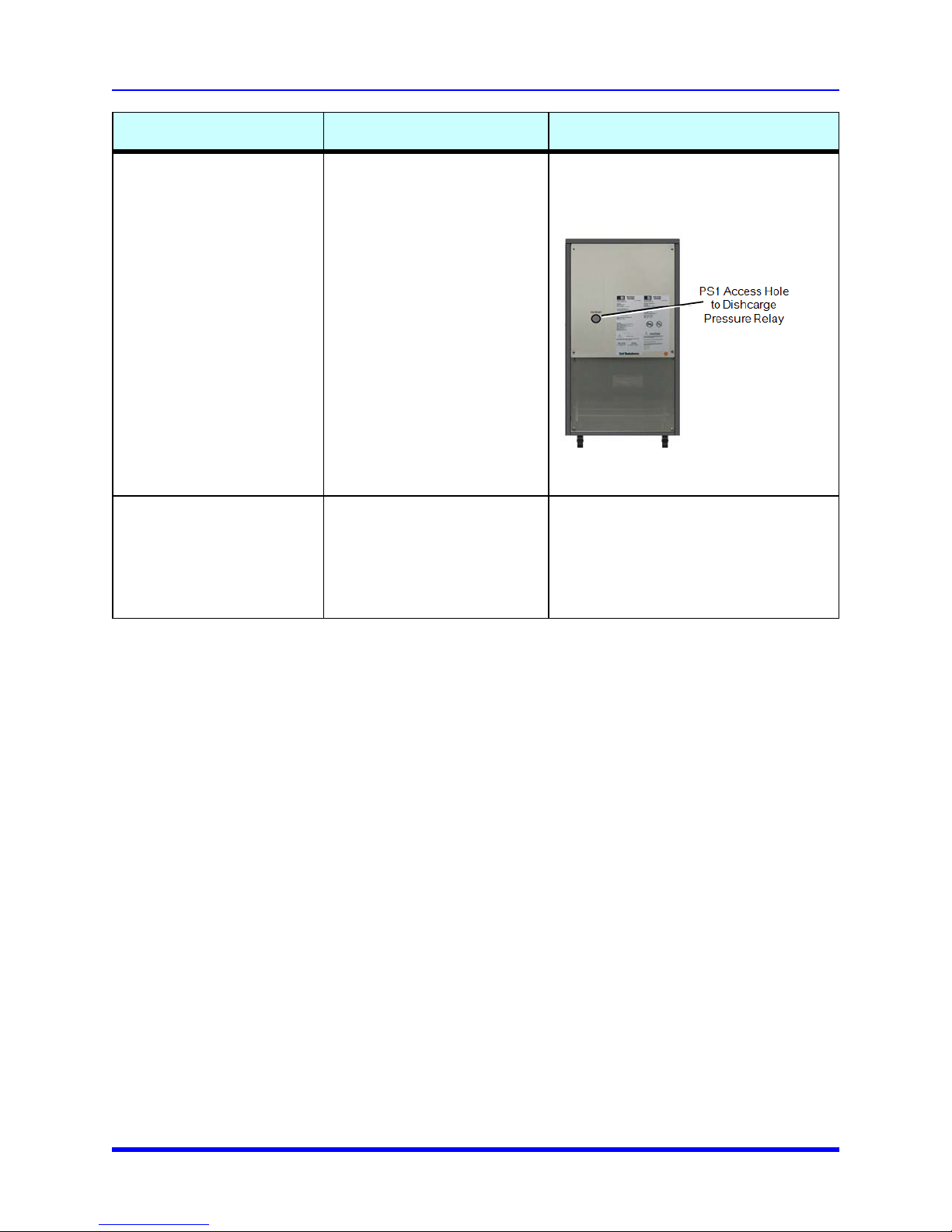
Reset the discharge pressure relay by
inserting a finger through the PS1 access
hole located on the back panel and
pushing the green reset switch forward.
Compressor stops running
and does not restart.
Inadequate cooling of the
cold probe
Excessive discharge pressure
Excessive heat load on the
Cold Probe
Contact a Polycold Service Center if the
problem persists.
Verify the probe is in proper ambient
pressure (1 torr or deeper vacuum). See if
there is excessive external frosting of the
trap housing. Defrost the probe and retest
the results. Contact a Polycold Service
Center if the problem persists.
5-31 Brooks Automation
Page 39

6. Parts and Service
User Manual Contacting Brooks Automation Technical Support
6. Parts and Service
Contacting Brooks Automation Technical Support
Have the following information ready before you contact Brooks Automation Technical Support.
1. Record the serial number.
Provide the location of the product.
2. Provide the name of the person to contact, e-mail address, and telephone number.
3. Describe the malfunctions observed during the failure.
4. Prepare a detailed description of the events leading up to the error.
5. Include:
l How long has the equipment been in operation?
l Was any work done on the equipment prior to the error?
l What command was the equipment performing when the error occurred.
l List all actions taken after the error was performed.
l What were the results of those actions?
l Is their any other information that may assist our Specialist?
Polycold Customer Support Information
Polycold Customer Support:
Accelerating Innovation 6-32
Page 40
6. Parts and Service
For Emergency after Hours Support User Manual
For Emergency after Hours Support
You can reach Brooks Global Customer Operations Teams around the world at the following phone
numbers:
Table 6-1: Technical Support Contact Information
Location GUTS® Contact Number
North America
Europe +49-1804-CALL-GUTS (+49-1804-2255-4887)
Japan +81-45-477-5980
China +86-21-5131-7066
Taiwan +886-3-5525225
Korea +82-31-288-2500
Singapore +65-6464-1481
Refer to the Brooks Automation web site (www.brooks.com) for additional contact information.
+1-800-FOR-GUTS (1-800-367-4887)
+1-978-262-2900
Packing and Shipping Instructions
If the Product is to be shipped, for return to Brooks or to another location, it must be properly packaged
to ensure it arrives undamaged.
NOTE: Use the original shipping crates when shipping the P-102. If the original crates have become
lost or damaged, use similar containers.
WARNING
Lockout / Tagout
The Product must be shut down and perform Lockout/Tagout
according to the procedure at your facility.
All shipping materials used to ship the P-102
Desiccant packs
Tools and Materials
Moisture, Shock, and Tip indicators as required
6-33 Brooks Automation
Fork lift
Page 41
6. Parts and Service
User Manual Packing and Shipping Instructions
Packing and Shipping Procedure
1. Turn off the P-102. Allow it to return to ambient temperature.
2. Unplug the P-102.
WARNING
Lockout / Tagout
The Product must be shut down and perform Lockout/Tagout
according to the procedure at your facility.
3. Use a fork lift to lift the P-102 onto the pallet in the shipping container.
4. Close the box and completely tape all the seams in the box shut.
5. Add tip indicators, shock indicators, moisture indicators or other indicator if necessary to the
outside of the shipping container. This provides information about proper handling during shipment.
Accelerating Innovation 6-34
Page 42
Appendix
Appendix A: Material Safety Sheets User Manual
Appendix
Appendix A: Material Safety Sheets
Table 0-1 identifies the materials that are contained or shipped with the P-102. Read and understand
the Material Safety Data Sheet (MSDS) for each material. These sheets provide crucial information
about the materials used in the equipment. The facility where the P-102 is to be used is responsible for
the maintenance and distribution of each MSDS. Ensure that the MSDSs are available in each
workplace.
Inert-HFC Polycold Refrigerant not considered a hazardous material as long as it is confined in the
hermetically sealed system. Be sure to be familiar with the MSDS.
Table 0-1: Hazardous Material Used in the Product
Material Location in Product Link
Inert-HFC Polycold® Refrigerant Internal as a closed loop to all lines in the refrigeration cycle PDF
I Brooks Automation
 Loading...