

Page 1

Technical/Programming Manual
FT128
Rev 2.2
For Software V2.2.x
FT128 CIE
MA355 August 2015
Page 2

This page has deliberately been left blank.
Page 3

Technical / Programming Manual
FT128 Rev 2.2
Table of Contents
1 Introduction ............................................................................................................................. 12
1.1 General introduction ................................................................................................................ 12
1.2 Definitions / Explanations ................................................................................................ ........ 12
2 Overview .................................................................................................................................. 13
2.1 FT128 CIE .............................................................................................................................. 13
2.2 Expansion Boards ................................................................................................................... 13
2.3 Power Supply .......................................................................................................................... 13
2.4 Software (S/W) Versions ......................................................................................................... 13
2.5 Documents.............................................................................................................................. 13
2.6 Applications ............................................................................................................................ 14
2.7 PC software (S/W) .................................................................................................................. 14
3 Control & Indicating Equipment ............................................................................................. 15
3.1 Technical Data ........................................................................................................................ 15
3.2 Control Panel Overview ........................................................................................................... 17
3.3 COM Loop .............................................................................................................................. 19
3.4 Programmable Voltage Outputs (S0-S1).................................................................................. 19
3.5 Programmable Relay Output (R0) ........................................................................................... 19
3.6 Programmable Input (I0) ......................................................................................................... 20
3.7 Relay Output for Routing Equipment (Fault TX) (R1) ............................................................... 20
3.8 24 VDC Power Supply Outputs ................................................................................................. 20
3.9 RS232 Interfaces ................................................................................................ .................... 21
3.10 RS485 Transceiver (Optional) ............................................................................................ 21
3.11 Power Supply ................................................................ ..................................................... 21
3.12 Internal Power supply ......................................................................................................... 21
4 Expansion Boards 458X .......................................................................................................... 22
4.1 8 Zones Expansion Board 4580 .............................................................................................. 23
4.1.1 Type of Zone Line Input ............................................................................................. 23
4.1.1.1 Zone Line Input (EOL Capacitor) ........................................................................ 23
4.1.1.2 Ex Zone Line Input (EOL Resistor) ..................................................................... 24
4.1.1.3 Zone Line Input (EOL Resistor) ................................ .......................................... 24
4.1.2 Input States................................................................................................................ 24
4.1.2.1 Normal State ................................ ................................................................ ...... 25
4.1.2.2 High Current State .............................................................................................. 25
4.1.2.3 Alarm State ........................................................................................................ 25
4.1.2.4 Short-Circuit State .............................................................................................. 25
4.1.2.5 Open Circuit State .............................................................................................. 25
4.1.2.6 Disconnected State ............................................................................................ 25
4.2 8 Relays Expansion Board 4581.............................................................................................. 25
4.3 Inputs and Outputs Expansion Board 4583 .............................................................................. 26
4.4 I/O Matrix Board 4582 ............................................................................................................. 27
4.4.1 I/O Matrix jumper link setting: ..................................................................................... 28
4.5 FT128 External Termination .................................................................................................... 29
5 Optional Modules .................................................................................................................... 31
5.1 AS1668 Fan Control ................................................................................................................ 31
5.1.1 Mode Control ................................ ................................ ............................................. 31
5.1.2 Fan Status ................................................................................................................. 31
5.1.3 Configuration and Programming ................................................................................. 32
5.1.4 Fan Reset .................................................................................................................. 34
5.1.5 Fan Front Display ....................................................................................................... 34
5.1.6 Supply Air Fan ........................................................................................................... 34
5.1.7 Smoke Exhaust / Spill Fan ................................................................ ......................... 35
5.2 Zone Control ........................................................................................................................... 37
3
Page 4

Technical / Programming Manual
FT128 Rev 2.2
5.2.1 Controls & Indications ................................................................................................ 37
5.2.2 Zone Control Configuration ........................................................................................ 37
5.3 Generic Applications ............................................................................................................... 38
5.3.1 Overview.................................................................................................................... 38
5.3.2 New mimic options ..................................................................................................... 39
5.3.3 Configuration and programming ................................................................................. 39
5.4 Occupant Warning System (OWS) ................................................................ .......................... 41
5.4.1 Overview.................................................................................................................... 41
5.4.2 Audio Amplifiers ......................................................................................................... 41
5.4.2.1 60/120 Watt Amplifier Module ................................ ............................................. 42
5.4.2.2 250 Watt Amplifier Module .................................................................................. 43
5.4.3 OWS Volume Adjustment ........................................................................................... 44
5.4.4 Auxiliary Audio inputs ................................................................................................. 44
5.4.5 OWS Dual Strobe Output ........................................................................................... 45
5.5 Gaseous extinguishing system control module ........................................................................ 46
5.5.1 Overview.................................................................................................................... 46
5.5.2 Display board (SUB929) & decal ................................................................................ 46
5.5.3 Control board (SUB928) ............................................................................................. 47
5.5.4 CIE interface board (SUB943) .................................................................................... 48
5.5.4.1 Inputs from FT128 to CIE interface board (SUB943) ........................................... 48
5.5.4.2 Outputs from CIE interface board (SUB943) to FT128 ........................................ 48
6 Peripheral Devices .................................................................................................................. 49
6.1 COM Loop Units ..................................................................................................................... 49
6.1.1 Input Units ................................................................................................................. 51
6.1.1.1 Analogue Sensor Bases (ASB) ........................................................................... 52
6.1.1.2 Addressable Manual Call Points ......................................................................... 52
6.1.1.3 Analogue Detectors ............................................................................................ 53
6.1.1.4 Conventional Detector Bases (CDB) ................................................................... 57
6.1.1.5 Conventional Detectors ...................................................................................... 57
6.1.1.6 Accessories ........................................................................................................ 58
6.1.2 Addressable I/O units ................................................................................................. 59
6.1.3 Alarm Devices (Addressable Sounders) ..................................................................... 60
6.1.4 Short Circuit Isolators (Addressable) .......................................................................... 62
6.1.5 Built-in Isolators ......................................................................................................... 63
6.1.6 Units for Hazardous (Ex) Areas .................................................................................. 63
6.1.6.1 Galvanic isolators / IS barrier units...................................................................... 63
6.1.6.2 Intrinsically Safe Mounting Bases ....................................................................... 63
6.1.6.3 Intrinsically Safe Photoelectric Smoke Detectors ................................................ 64
6.1.6.4 Intrinsically Safe Heat Detectors ......................................................................... 64
6.1.7 Intrinsically Safe Manual Call Points ........................................................................... 64
6.1.8 Other COM Loop Units ............................................................................................... 64
6.2 Units Connected To Optional RS485 Interface ........................................................................ 66
6.2.1 Alert Annunciation Units ............................................................................................. 66
6.2.2 External Presentation Units ........................................................................................ 67
6.3 Units Connected To RS232 Interface J5 (On 4556) ................................................................. 68
6.3.1 Web-servers............................................................................................................... 68
6.4 Units Connected To RS232 Interface J3 (On 4556) ................................................................. 68
6.5 Other Units.............................................................................................................................. 69
6.5.1 External LEDs ............................................................................................................ 69
6.5.2 Alarm Devices (Sounders, Etc.) .................................................................................. 69
6.5.3 Magnetic Door Holders............................................................................................... 69
6.5.4 Duct Detector Chambers ................................................................ ............................ 70
7 Programmable Inputs .............................................................................................................. 71
4
Page 5

Technical / Programming Manual
FT128 Rev 2.2
7.1 Control Unit Input I0 ................................................................................................................ 71
7.1.1 Not supervised ........................................................................................................... 71
7.1.2 Supervised ................................................................................................................. 72
7.2 Input 0-4 in Expansion Board 4583 .......................................................................................... 72
7.2.1 Not supervised ........................................................................................................... 72
7.2.1 Supervised ................................................................................................................. 72
7.3 3361 Unit Inputs In0 / Z & In1 ................................................................................................ .. 72
7.3.1 Input In0..................................................................................................................... 72
7.3.2 Input In1..................................................................................................................... 72
8 Input Programming ................................................................................................................. 73
8.1 Type (Trigger Conditions) ........................................................................................................ 73
8.2 Comments on Trigger Conditions: ........................................................................................... 74
8.3 Logic ....................................................................................................................................... 76
8.3.1 Not Supervised (Default) ............................................................................................ 76
8.3.2 Supervised ................................................................................................................. 76
9 Programmable Outputs ........................................................................................................... 77
9.1 Control Unit Outputs S0 – S1 .................................................................................................. 78
9.2 Control Unit Output R0 ............................................................................................................ 79
9.3 8 Relay Outputs Expansion Board 4581 Output 0 – Output 7 ................................................... 79
9.4 Inputs and Outputs expansion board 4583 Output 0–1 ............................................................ 79
9.5 3361 Unit Outputs Re0 – Re1.................................................................................................. 79
9.6 3364 Unit Outputs VO0, VO1 & VO2 ....................................................................................... 79
9.7 The 4477 Unit Output (Siren)................................................................................................... 80
9.8 The 3379 Unit Output (Sounder).............................................................................................. 80
9.9 The 4380 unit output (beacon) ................................................................................................. 80
9.10 The 4383 unit output (Light indicator) ................................................................................. 80
10 Output Programming .............................................................................................................. 81
10.1 Type of output ................................................................................................ .................... 81
10.1.1 Comments to the types........................................................................................... 81
10.2 Logic ................................................................................................ .................................. 81
10.3 Supervised / Non-supervised .............................................................................................. 81
10.4 Output Signal Period .......................................................................................................... 82
10.4.1 Types of output signal periods ................................................................................ 82
10.4.2 Timing of output signal periods ............................................................................... 82
10.5 Control Expression ............................................................................................................. 84
10.5.1 Trigger Conditions ................................................................ .................................. 84
10.5.1.1 Alarm ................................................................................................................. 85
10.5.1.2 Interlocking ........................................................................................................ 85
10.5.1.3 Disablement....................................................................................................... 86
10.5.1.4 Other ................................................................................................................. 86
10.5.1.5 Comments to the Trigger Conditions (Functions): ............................................... 87
10.6 Logical Operators ............................................................................................................... 90
10.6.1 Control Expression Examples ................................................................................. 90
10.6.1.1 AND .................................................................................................................. 90
10.6.1.2 OR ..................................................................................................................... 90
10.6.1.3 NOT .................................................................................................................. 90
10.6.1.4 Parentheses ...................................................................................................... 91
10.6.1.5 Control Expressions ........................................................................................... 91
11 Short Circuit Isolators ............................................................................................................. 92
12 Interlocking Function .............................................................................................................. 94
12.1 Interlocking Programming ................................................................................................... 94
12.1.1 Interlocking Output ................................................................................................ . 94
12.1.2 Interlocking Input .................................................................................................... 95
5
Page 6

Technical / Programming Manual
FT128 Rev 2.2
12.1.3 Interlocking Combination ........................................................................................ 95
12.2 Interlocking Indications ................................................................ ....................................... 96
12.3 Information of Interlocking Combinations (H9) .................................................................... 97
12.3.1 Activated Interlocking outputs / inputs (H9/C1)........................................................ 97
12.3.2 Activate / deactivate Interlocking Output (H9/C2) .................................................... 97
12.3.3 Reset interlocking output (H9/C3) ........................................................................... 97
12.3.4 Disable Interlocking Output (H9/C4) ....................................................................... 97
12.3.5 Re-enable Interlocking Output (H9/C5) ................................................................... 98
12.4 Interlocking Control Expressions ........................................................................................ 98
13 Fire Door Closing Function..................................................................................................... 99
14 Functions / Services / Features ............................................................................................ 100
14.1 Sensor Value ................................................................................................................... 100
14.2 Week Average Sensor Value ............................................................................................ 100
14.3 Decision Value ................................ ................................................................ ................. 101
14.4 Alarm Algorithms for Smoke Detectors / Detection Levels / Offsets ................................... 101
14.4.1 Alarm Algorithm / Alternative Alarm Algorithm....................................................... 101
14.4.2 Filtering Algorithm ................................................................................................ 102
14.4.3 Smouldering Smoke Algorithm ............................................................................. 103
14.4.4 Performance Factor.............................................................................................. 105
14.5 Algorithms for Analogue Heat Detectors ........................................................................... 105
14.5.1 Class A1 Algorithm ............................................................................................... 106
14.5.2 Class A2 S Algorithm ........................................................................................... 106
14.5.3 Class B S Algorithm ............................................................................................. 106
14.6 Self Verification ................................................................................................................ 107
14.7 Minimum / Maximum Sensor Values ................................................................................. 107
14.8 2-Zone / 2-Address Dependence (Co-Incidence Alarm) .................................................... 108
14.8.1 2-Zone dependence ............................................................................................. 108
14.8.2 2-Address (-Unit) Dependence ............................................................................. 109
14.8.3 Reset of 2-Zone / 2-Address Dependence (Co-Incidence Alarm) .......................... 109
14.9 Delayed Alarm ................................................................................................................. 109
14.9.1 General time delay application.............................................................................. 109
14.9.2 Specific time delay application .............................................................................. 110
14.10 Alarm Verification Facility (AVF) ....................................................................................... 111
14.11 Alert Annunciation ............................................................................................................ 111
14.12 Alert Annunciation Applications ........................................................................................ 112
14.12.1 Alarm Acknowledgement Facility (AAF) ................................................................ 112
14.12.2 Local Alarm Acknowledgement (LAA) ................................................................... 114
14.13 Quiet Alarm ...................................................................................................................... 115
14.14 Fire Alarm Type A and Fire Alarm Type B......................................................................... 115
14.14.1 Fire Alarm Type B ................................................................................................ 116
14.14.2 Fire Alarm Type A ................................................................................................ 116
14.15 Disable Zones, Alarm Points, Outputs, Etc. ...................................................................... 116
14.15.1 Disable Zone ........................................................................................................ 117
14.15.2 Disable Zone - Address ........................................................................................ 117
14.15.3 Disable Control Output ......................................................................................... 117
14.15.4 Disable all Control, Ventilation, Extinguishing or Interlocking Outputs ................... 117
14.15.5 Disable / Re-Enable Alarm Devices ...................................................................... 117
14.15.6 Disable / Re-enable Outputs for Routing Equipment ............................................. 117
14.15.7 Disable / Re-enable alert annunciation function .................................................... 117
14.15.8 Disconnect / Re-Connect COM Loop .................................................................... 117
14.15.9 Disconnect / Re-connect Zone Line Input ............................................................. 117
14.15.10 Disconnect / Re-connect addressable zone interface input ............................... 118
14.15.11 Disable Interlocking Output ............................................................................... 118
14.16 Test Mode ........................................................................................................................ 118
6
Page 7

Technical / Programming Manual
FT128 Rev 2.2
14.17 Test Alarm Devices .......................................................................................................... 118
14.18 Test of Routing Equipment ............................................................................................... 118
14.19 Calibration of Supervised Outputs .................................................................................... 118
14.20 Service Signal ................................................................ .................................................. 119
14.21 Fault Signal (Fault Condition) ........................................................................................... 119
14.22 Alarm Texts ...................................................................................................................... 119
14.22.1 Creating Alarm Texts via EBLWin ......................................................................... 120
14.22.2 Downloading Texts to EPU 1728 and AAU 1736 .................................................. 122
14.23 Real Time Clock (RTC) .................................................................................................... 122
14.23.1 Daylight Saving Time ........................................................................................... 122
14.24 Time Channels 1-14 ......................................................................................................... 122
14.25 Time Channels 15-63 ....................................................................................................... 122
14.26 Event Log......................................................................................................................... 123
14.27 Loss of Main Power Source .............................................................................................. 123
14.27.1 Fault: Loss of main power source ......................................................................... 123
14.27.2 LCD Backlight ...................................................................................................... 123
14.28 Zone Groups .................................................................................................................... 123
15 Special New Zealand Functions ........................................................................................... 124
15.1 Alarm Devices .................................................................................................................. 124
15.1.1 Silence Alarm Devices (Inside Switch) .................................................................. 124
15.1.2 New Zealand FB Silence Switch (Outside Switch) ................................................ 124
15.1.2.1 Isolated Alarm .................................................................................................. 125
15.2 Battery Faults ................................................................................................................... 125
15.2.1 FAULT: Battery ................................................................ .................................... 125
15.2.2 FAULT: Low Battery Capacity (Auto battery test) .................................................. 125
15.3 Watchdog Reset............................................................................................................... 126
15.4 Routing Equipment Isolate (Disable) ................................................................................. 126
15.5 Acknowledged Alarm ........................................................................................................ 126
16 Advanced Mode ..................................................................................................................... 127
16.1 Pulse Up – Down Counter ................................................................................................ 128
16.1.1 Pulse Up – Down Counter For Smoke .................................................................. 128
16.1.2 Pulse Up – Down Counter for Temperature .......................................................... 128
16.1.3 Pulse Up – Down Counter for Smoke & Temperature ........................................... 129
16.2 Fire Judgement ................................................................................................................ 129
16.3 Alarm Threshold Levels .................................................................................................... 129
16.4 Alarm Delay Time ............................................................................................................. 129
16.5 Learning function / Learning period................................................................................... 131
16.5.1 Area Alarm algorithms .......................................................................................... 131
16.5.1.1 Smoke Steam, Level 1 ..................................................................................... 131
16.5.1.2 Heating area, level 2 ................................ ........................................................ 132
16.5.1.3 Cooking – Welding Area, level 3 ...................................................................... 132
16.5.1.4 Clean Area, level 1, 2 & 3 ................................................................................ 132
16.5.1.5 Learning Function Summary ............................................................................ 132
16.6 Analogue Data Output ...................................................................................................... 132
16.7 Sensitivity Compensation ................................................................................................. 132
16.8 Self-Diagnosis of Internal Devices .................................................................................... 133
16.9 Address Setting Check ................................................................ ..................................... 133
16.10 Polling LED ...................................................................................................................... 133
17 Control Unit Properties (Settings) ........................................................................................ 134
17.1 Control Unit Properties Dialog Box ................................................................................... 134
17.1.1 General Information.............................................................................................. 134
17.1.2 Configuration........................................................................................................ 134
17.1.3 Misc. .................................................................................................................... 134
17.2 EBLWin Control unit pop-up menu.................................................................................... 135
17.2.1 Reset alarm counter ............................................................................................. 135
7
Page 8

Technical / Programming Manual
FT128 Rev 2.2
17.2.2 Software version .................................................................................................. 135
17.2.3 Show event log .................................................................................................... 135
17.2.4 Restart ................................................................................................................. 136
17.2.5 Delete ................................................................ .................................................. 136
17.2.6 Properties ............................................................................................................ 136
17.2.7 Add Web-server ................................................................................................... 136
18 System Properties (Settings) ................................................................................................ 137
18.1 System Properties Dialog Box .......................................................................................... 137
18.1.1 Name ................................ ................................................................ ................... 137
18.1.2 User Definable Text.............................................................................................. 137
18.1.3 System Properties, Page 1 ................................................................................... 137
18.1.3.1 Alert Annunciation ............................................................................................ 137
18.1.3.2 Alarm Acknowledgement Facility ...................................................................... 138
18.1.3.3 Disable routing equipment by door switch ........................................................ 138
18.1.3.4 Alarm Reset Method ........................................................................................ 138
18.1.3.5 Alarm Delay Time (Seconds)............................................................................ 139
18.1.4 System Properties, Page 2 ................................................................................... 139
18.1.4.1 Door Closing By Time ...................................................................................... 140
18.1.4.2 Main Power Loss Fault Delay Time (Minutes)................................................... 140
19 EBLWin menus ................................ ................................................................ ...................... 141
19.1 The File Menu ................................................................................................ .................. 141
19.1.1 New ..................................................................................................................... 141
19.1.2 Open .................................................................................................................... 141
19.1.3 Import from Win512 .............................................................................................. 141
19.1.4 Report .................................................................................................................. 141
19.1.5 Save .................................................................................................................... 141
19.1.6 Save As ............................................................................................................... 142
19.1.7 Print labels ........................................................................................................... 142
19.1.8 Exit ...................................................................................................................... 142
19.2 The View menu ................................................................................................................ 142
19.2.1 Filter Box.............................................................................................................. 142
19.2.2 Tree view ............................................................................................................. 143
19.2.3 Deviations ................................ ................................................................ ............ 143
19.2.4 Selected loop ....................................................................................................... 143
19.2.5 Alarm points ......................................................................................................... 144
19.2.6 Interlocking combinations ..................................................................................... 144
19.2.7 External faults ...................................................................................................... 144
19.2.8 Technical warnings .............................................................................................. 145
19.2.9 External time channels ......................................................................................... 145
19.3 The System menu ............................................................................................................ 145
19.3.1 Properties ............................................................................................................ 145
19.3.2 Time Channels ..................................................................................................... 146
19.3.3 Alarm Algorithms .................................................................................................. 148
19.3.3.1 Parameters for Smoke Algorithms .................................................................... 149
19.3.3.2 Parameters for Heat Algorithms ....................................................................... 149
19.3.3.3 Parameters for Combined Decision Algorithm .................................................. 150
19.3.4 Output Signal Periods .......................................................................................... 150
19.3.5 National Holidays ................................................................................................. 151
19.3.6 Two zone dependence ......................................................................................... 152
19.3.7 Zone groups ......................................................................................................... 152
19.3.8 System information .............................................................................................. 153
19.3.9 Edit Alarm texts .................................................................................................... 153
8
Page 9

Technical / Programming Manual
FT128 Rev 2.2
19.3.10 User data ............................................................................................................. 153
19.4 The Tools menu ............................................................................................................... 154
19.5 The Help menu ................................................................................................................ 156
20 Download SSD ....................................................................................................................... 157
20.1 COM loop menu ............................................................................................................... 157
20.1.1 Check Loop .......................................................................................................... 157
20.1.2 Auto generate SSD .............................................................................................. 158
20.2 SSD download to the Control Unit .................................................................................... 158
20.3 User definable text messages download ........................................................................... 159
21 Download software (S/W) ...................................................................................................... 160
21.1 Software Download to the FT128 (CIE) ............................................................................ 160
22 Cable Types ........................................................................................................................... 162
22.1 COM Loop Cables ............................................................................................................ 162
22.2 Remote Display Units Cables ........................................................................................... 162
22.3 Conventional Zone Line Cables ................................ ........................................................ 162
22.4 Alarm Device Cables ........................................................................................................ 162
22.5 Other Equipment Cables .................................................................................................. 162
23 FT128 cable length calculation ............................................................................................. 164
23.1 COM Loop Cable Length .................................................................................................. 164
23.2 Cable Length Calculations for 1728 and 1736................................................................... 166
24 Current Consumption ........................................................................................................... 168
25 Power Supply ........................................................................................................................ 171
25.1 Charger Functions ............................................................................................................ 171
25.1.1 Battery Charging Functions: ................................................................................. 172
25.1.2 Battery Protection Functions ................................................................................. 172
25.2 Current Consumption Calculations ................................................................................... 173
25.3 Main Power Source (Power Supply) ................................................................................. 173
25.4 Standby Power Source (Battery) ...................................................................................... 173
26 S/W Versions ......................................................................................................................... 174
27 National Regulations / Requirements ................................................................................... 175
27.1 Conventions ..................................................................................................................... 175
27.2 Language ......................................................................................................................... 175
28 Drawings / Connection Diagrams ......................................................................................... 176
29 Revision History .................................................................................................................... 180
29.1 Revision History Table ..................................................................................................... 180
29.2 Software Revision 2.2.0 Modifications ................................ .............................................. 180
29.2.1 New common features and additions .................................................................... 180
29.2.2 New or modified features in EBLWin only ............................................................. 181
29.2.3 New or modified feature in system software EBL only ................................ ........... 181
Table of Figures
Figure 1 FT128 Control & Indicating Equipment ............................................................................................... 17
Figure 2 The FT128 Front Membrane............................................................................................................... 17
Figure 3 Expansion Boards (from left to right) 4580, 4581 and 4583. ................................................................ 22
Figure 4 I/O Matrix board 4582 ........................................................................................................................ 22
Figure 5 Expansion Board 4580 Top Side Differences ...................................................................................... 24
Figure 6 I/O Matrix Board Application Overview ............................................................................................... 27
Figure 7 I/O Matrix PCB layout......................................................................................................................... 28
9
Page 10

Technical / Programming Manual
FT128 Rev 2.2
Figure 8 SUB836 Adaptor Board ...................................................................................................................... 30
Figure 9 SUB835 external Terminal Board ....................................................................................................... 30
Figure 10 Supply Air Fan Timing Sequence...................................................................................................... 35
Figure 11 Smoke Exhaust Or Spill Fan Timing ................................................................................................. 35
Figure 12 AS1668 Fan Control Example .......................................................................................................... 36
Figure 13 Zone control application ................................................................................................................... 37
Figure 14 Mimic Board Options ........................................................................................................................ 39
Figure 15 Generic application, NZ index panel ................................................................................................. 40
Figure 16 Occupant Warning Display Module ................................ ................................................................... 41
Figure 17 Class-D 60W / 120W Audio Amplifier Board Layout .......................................................................... 42
Figure 18 60W / 120W Audio amplifier photos .................................................................................................. 42
Figure 19 Class-D 250W Audio Amplifier Board Layout .................................................................................... 43
Figure 20 Typical OWS Dual Strobe Control Circuit ................................................................ .......................... 45
Figure 21 Gas Extinguishing Display Layout ................................................................................................ ..... 47
Figure 22 Assembled Control & Interface Boards ............................................................................................. 48
Figure 23 EBLWin Properties Dialog Box for 4301/4401 (Normal Mode)............................................................ 51
Figure 24 Decision Algorithm Graph. ................................................................................................................ 55
Figure 25 Connection example of 2A MDH power supply .................................................................................. 69
Figure 26 EBLWin “Input” dialog Boxes ............................................................................................................ 71
Figure 27 EBLWin "Voltage" & "Relay” Output Dialog Boxes Respectively ........................................................ 77
Figure 28 EBLWin 3379 and 4477 Dialog Box .................................................................................................. 78
Figure 29 Signal Output Periods ...................................................................................................................... 83
Figure 30 Control expression output dialog box ................................................................................................ 84
Figure 31 Short Circuit Isolators example in FT128........................................................................................... 92
Figure 32 Filter function ................................................................................................................................... 94
Figure 33 The EBLWin "Interlocking Combination" dialog box ........................................................................... 95
Figure 34 Fire Alarm Level Graph for the Analogue Smoke Detector ............................................................... 101
Figure 35 Filtering Algorithm N-15 Graph ....................................................................................................... 103
Figure 36 An example with the smouldering smoke algorithm. ........................................................................ 104
Figure 37 Sensor Log in Graphical Form ........................................................................................................ 108
Figure 38 Sensor Log in Tabulated Form ....................................................................................................... 108
Figure 39 Alert Annunciation function. ............................................................................................................ 111
Figure 40 Alarm Acknowledgement Facility Units ........................................................................................... 112
Figure 41 Alarm Acknowledgement Facility (AAF) Flow Chart ......................................................................... 113
Figure 42 Local Alarm Acknowledgement Facility Connection Diagram ........................................................... 115
Figure 43 The EBLWin "Control Unit Properties" Dialog Box. .......................................................................... 134
Figure 44 EBLWin System Properties Dialog Box, Page 1 and 2 ..................................................................... 137
Figure 45 Deviation Tab ................................................................................................................................ 143
Figure 46 Selected Loop Tab ......................................................................................................................... 144
Figure 47 Time Channels Dialog Box. ............................................................................................................ 146
Figure 48 Configuring Time Channels ............................................................................................................ 146
Figure 49 Time Channel Setting ..................................................................................................................... 147
Figure 50 Editing Time Channel Intervals ....................................................................................................... 147
Figure 51 Alarm Algorithms Dialog Box .......................................................................................................... 148
Figure 52 Alarm Algorithms for Various Detectors........................................................................................... 148
Figure 53 Outputs Signal Periods Dialog Box ................................................................................................. 150
Figure 54 National Holidays Dialog Box ......................................................................................................... 151
Figure 55 Example Setting for National Holidays ............................................................................................ 152
Figure 56 EBLWin menu "Tools". ................................................................................................................... 154
Figure 57 COM Loop Current Consumption vs. Cable Length ......................................................................... 165
10
Page 11

Technical / Programming Manual
FT128 Rev 2.2
Figure 58 Access Summary of Loop Units with Current Consumption in EBLWin ............................................. 170
Figure 59 FT128 Power Supply Block Diagram. ............................................................................................. 171
Figure 60 EBLWin Settings Dialog Box .......................................................................................................... 175
Figure 61 FT128 General Arrangement .......................................................................................................... 177
Figure 62 FT128 Standard Block Wiring Diagram ........................................................................................... 178
Figure 63 NZFT128 Block Wiring Diagram for NZ ........................................................................................... 179
List of Tables
Table 1 Control Panel Specifications ................................................................................................................ 15
Table 2 Control Panel Limitation ...................................................................................................................... 16
Table 3 Expansion Boards Allowed .................................................................................................................. 22
Table 4 Expansion boards address setting ....................................................................................................... 23
Table 5 4580 Versions with EOL Values to Use ................................................................................................ 24
Table 6 I/O Matrix board 4582 type setting ....................................................................................................... 28
Table 7 OWS 60/120W amplifier specifications ................................................................................................ 43
Table 8 OWS 250W amplifier specifications ..................................................................................................... 44
Table 9 Connection of the Audio Amplifier 60W, 120W and 250W ..................................................................... 44
Table 10 Gas Front Status LED Indication and flash Pattern ............................................................................. 47
Table 11 Control Unit Inputs I0 & 4583 Inputs 0-4 ............................................................................................. 72
Table 12 Output signal period for the programmable output .............................................................................. 83
Table 13 Smoke detector alarm algorithm ...................................................................................................... 102
Table 14 Alarm acknowledgement function .................................................................................................... 114
Table 15 Summary of Recommended Cables................................................................................................. 163
Table 16 Distance away from CIE that Display Units can be located. .............................................................. 167
Table 17 FT128 and CIE Options Current Consumption ................................................................................. 168
Table 18 COM Loop Output Units Current Consumption ................................................................................. 169
Table 19 Other Units Current Consumption .................................................................................................... 170
Table 20 Software Versions ........................................................................................................................... 174
Table 21 Drawing Lists .................................................................................................................................. 176
11
Page 12

1 Introduction
1.1 General introduction
FT128 Technical / Programming Manual is a document with information of special interest
for planning engineers as well as service / commissioning engineers.
This document should be read in conjunction with FT128 Operation Manual, since most of
the information in one of the documents is not found in the other document and vice versa.
It should also be read in conjunction with the FT128 connection diagrams according to the
drawings / connection diagram list on Table 21 page 176.
When planning a fire alarm installation, the Australian standard AS1670.1 requirements
must be followed. Detector type, detector coverage area, detector spacing and special
applications in the building, etc. are concerns for the planning engineers and are not
covered in this document.
Due to continual development and improvement, different software versions are to be
found. This document is valid for FT128 S/W version 2.2.x .On the date of this document
is x=0.
FT128 S/W version 2.2.x supports some functions require the FT128 main board 4556
with PCB no. 9285-5A and the later version PCB no. 9285-6A.
Technical / Programming Manual
FT128 Rev 2.2
Hardware H/W
A H/W (e.g. a printed circuit board) has:
A part number (e.g. 4556)
A product name (e.g. FT128 Main board 255 addresses)
A PCB no (e.g. 9285-6A)
Sometimes a software (S/W) downloaded.
Software S/W
A S/W has:
A version number (e.g. V2.2.x)
Sometimes additional information, such as Convention (different functions /
facilities), Language, etc. added.
PC S/W
A PC S/W is a program used for programming, commissioning, etc e.g. EBLWin. It has a
version number (e.g. EBLWin V2.2.x).
1.2 Definitions / Explanations
Definitions / explanations / abbreviations / etc. frequently used, refer to FT128 Operation
Manual for more details.
Refer to FT128 Operation Manual for more details.
12
Page 13
2 Overview
Product type
Product name
4580
8 Zones Expansion Board
4581
8 Relay Outputs Expansion Board
4583
Inputs And Outputs Expansion Board
1
2
2.1 FT128 CIE
FT128 is a microprocessor controlled intelligent fire alarm CIE intended for analogue
addressable smoke and heat detectors. Also conventional detectors and manual call points
can be used. Programmable inputs, control outputs and I/O units are available. Up to 255
addresses can be connected to FT128 loaded with EBL128 system software ≥ V2.0.x1.
FT128 is designed and assessed to the Australian Standard AS7240.2, AS7240.4 and
NZS4512:2003. The Fire Brigade Panel controls and indicators are incorporated as part of
the faceplate and conform to AS4428.3.
2.2 Expansion Boards
Up to four expansion boards can be mounted in FT128 CIE. The following expansion board
types are available:
Technical / Programming Manual
FT128 Rev 2.2
For more details, refer to chapter “Expansion Boards ”, page 22 and drawings F728, F729
and F731.
2.3 Power Supply
The primary power source is a switch mode power supply 230 VAC, 0.6 A / 24 VDC, 1.8 A
(40 Watt)2.
The standby power source is a backup battery (2 x 12V). Up to 24 AH batteries can be
fitted in the standard FT128 cabinet.
The batteries and the power supply output are connected to the Main board (4556). See
chapter “Power Supply”, page 171 for more information.
2.4 Software (S/W) Versions
Due to continual development and improvement, S/W versions are being updated from
time to time. The control unit S/W can be updated on site.
2.5 Documents
The following documents are available:
Technical / Programming Manual (this document)
Operation Manual
Connection diagrams
Information found in one document is normally not to be found in another document, i.e.
the documents complement each other. Product Leaflet for FT128 and other units are
available as PDF documents on Brooks web site: http://www.brooks.com.au.
Earlier software versions e.g. Win 128 V1.x.x supports only 128 addresses.
Meanwel power supply 40W is obsoleted and has currently been replaced with 75W
13
Page 14
2.6 Applications
FT128 is intended for small and medium size installations. The intelligent control unit offers
the system designer and end user a technically sophisticated range of facilities and
functions. Programming (via PC S/W EBLWin) and commissioning is very easy.
2.7 PC software (S/W)
The PC program EBLWin is used for programming and commissioning of FT128, i.e. to:
Autogenerate, i.e. to identify the units connected on a COM loop and make default
settings, which can be edited, saved and used as site specific data (SSD).
Create / download / upload (backup) the site specific data (SSD)
Download new system S/W version, settings, conventions, configurations, control
unit & system properties, etc.
Create / download the user definable alarm text messages shown in the display in
FT128, External Presentation Units (1728) and/or Alert Annunciation Units (1736).
Display the fire alarms, faults and disablements as well as reset, acknowledge and
re-enable, etc.
Technical / Programming Manual
FT128 Rev 2.2
Configure the Web-server II (1598); create and download / make a backup (upload)
of the configuration data as well as download of Web-server software.
The EBLWin S/W must have the same version number as the system software EBL128
version number, e.g. 2.2.x. Only x may be different, it indicates a small correction and is
not required to be the same.
Old SSD files can be opened in a newer (higher) version of EBLWin, saved, edited and
thereafter downloaded to an FT128 with the corresponding version. If a backup is required,
use the same EBLWin version as the system software EBL128 version.
Notes: EBLWin is not backward compatible with any version of Win128 i.e. SSD files
saved in EBLWin cannot be opened with Win128.
It is highly recommended to backup (upload) the SSD file before the system
software (EBL128) can be downloaded,
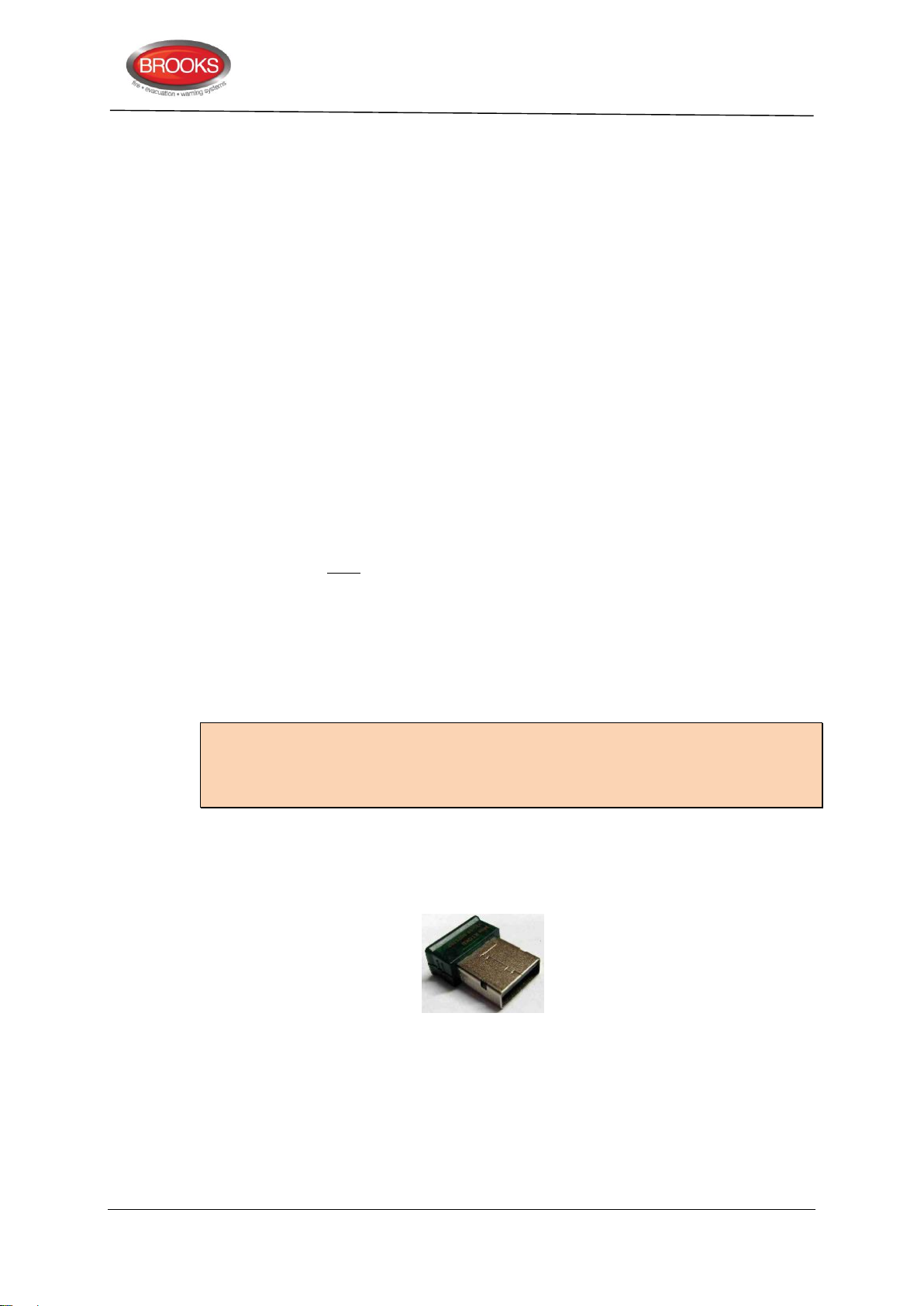
EBLWin key 5094 is a USB dongle that is required on your PC in order to gain access to
log on and download SSD files.
14
Page 15

Technical / Programming Manual
Technical Data
Mains Voltage
230VAC, 1.6A
system voltage
24VDC 3, Nominal
Current Consumption
Quiescent / alarm current is dependent on other equipment fitted
in FT128, type and number of expansion boards, connected
external equipment, etc. Refer to chapter "Current
Consumption”, page 168.
Ambient
Temperature
Operating
- 5 to + 40 C
Storage
- 40 to + 75 C
Ambient Humidity (% RH)
Max.95, non-condensing
Size H x W x D
(mm)
Standard
630 x 450 x 220 (including door)
Large
920 x 450 x 220 (including door)
Enclosure Material
1.5 Zinc anneal steel
Colour (metal cabinet)
Oyster, powder coated ripple finish
Approvals
Australian: Conform to AS7240-2, 7240-4 and AS4428.3
New Zealand: Conforms to NZS4512:2003
Inputs
1 COM loop for 255 addresses.
1 programmable input I0
Outputs
2 programmable supervised voltage outputs S0-S1
1 programmable relay output R0
1 Non-programmable relay output for fault condition R1
1 programmable relay, driven via S0, 2 changeover contacts
available on the termination board.
RS232 Interface for Web-server 1598
Optional RS485 output for remote display units
Power supply (2 x 24 VDC) for Web-server, external equipment,
etc.
3
3 Control & Indicating Equipment
3.1 Technical Data
The specifications of FT128 Control Panel are shown in Table 1 below and the system
limitations are shown in Table 2 on the next page.
Table 1 Control Panel Specifications
FT128 Rev 2.2
The rated output voltage is 24 VDC ± 1% for the main power source. Maximum ripple 240 mVp-p. The rated output voltage for
the second power source (backup battery) is 20-27 VDC.
15
Page 16

Table 2 Control Panel Limitation
Item
CIE
Fire alarms (presented in the FT128 display as ZONE and/or
ZONE-ADDRESS)4
256
Number of zones
994
Faults
200
External faults
50
Technical warnings
50
Short Circuit Isolators
64
Loop units
255
Trigger conditions (in all the control expressions)
Approx. 1000
Interlocking Combinations
100
3379 + 4477 units
50
Total number of detectors and/or Manual Call Points
5125
Max. number of AAF zones
50
Max. number of detectors per AAF zone
5
Max. number of I/O Matrix boards with expansion boards.
Number without expansion boards.
4
8
Max. number of expansion boards 4580, 4581 & 45836
6
Max. number of outputs per CIE including all kinds of outputs
200
Max. number of inputs
128
Max. number of 4380 units
10
4
5
6
Technical / Programming Manual
FT128 Rev 2.2
Up to 256 ZONEs and/or ZONE-ADDRESSES can be programmed but only the zone numbers 01-99 can be used.
Max. number of alarm points per CIE (microprocessor) is 512 (including conventional alarm points) and maximum number of
alarm points per zone is 32. Care must be taken in order not to exceed 512 detectors and/or Manual Call Points connected to
the CIE i.e. 255 COM loop units + 257 conventional detectors / MCP.
Expansion boards are internally connected to COM loop 0, ensure total number of expansion boards and I/O matrix boards
connected to the COM loop does not exceed 4. Software 2.1.1 allows to use 4 expansion boards.
16
Page 17
3.2 Control Panel Overview
Technical / Programming Manual
FT128 Rev 2.2
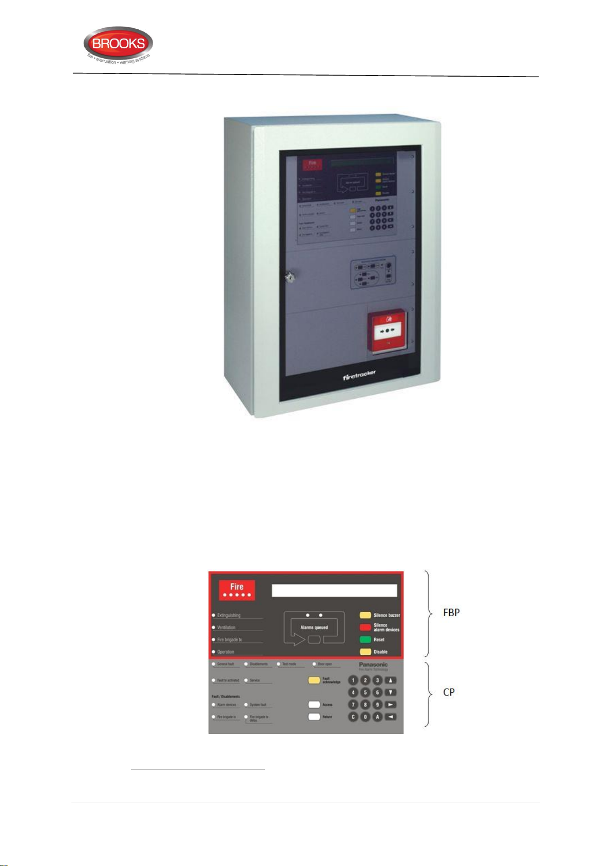
Figure 1 FT128 Control & Indicating Equipment
The FT128 Control and Indicating Equipment (CIE) shown in Figure 1 is housed in a metal
cabinet powder coated oyster colour. The cabinet has an inner and outer door. The outer
door is fitted with a 003 key to provide access level 1 and is made of tinted high impact
plastic and allows easy viewing of all indicators and controls.
Access to the inner door is gained by first opening the outer door which then provides
access to the inner door fixing screws.
Opening the inner door allows access to the control unit hardware for the purpose of
maintenance or servicing.
Figure 2 The FT128 Front Membrane.
The Fire Brigade panel (FBP) as shown in Figure 2 forms integral part of the Control Panel
(CP) and is used by the Fire Brigade or fire services personnel to inspect which alarm point
/ zone having activated fire alarm and to take the required operational control of the system.
17
Page 18

Technical / Programming Manual
FT128 Rev 2.2
In the display (LCD, 2x40 alphanumeric characters), the information displayed on the first
row is dependent on how many alarm points / zones having activated fire alarm (and also
convention).
On the second row, the activated alarm point / zone will be shown with an alarm text, if
programmed. For more detailed information regarding the fire alarm presentation, see the
FT128 Operation Manual.
Required Fire Brigade personnel manoeuvres are performed via the FBP in FT128.
The Control Panel (CP) is used by the FT128 owner, service personnel, etc. to
"communicate" with FT128, e.g. for commissioning, monthly tests, disablements and
maintenance. Access codes for different access levels are required. A keypad is used to
get access to the menu tree, i.e. the main and sub menus for data in / out, manoeuvres,
etc. The CP also holds several system status LEDs.
FT128 in its basic configuration is equipped with:
Oyster metal cabinet with acrylic door
Main board 4556 with:
One COM loop (0) to which the loop units are connected. For connections
and more information, see drawing F665 & F666.
Two programmable supervised voltage outputs (S0-S1). Connections and
more information, see drawing F665.
One programmable relay output (R0). Default programmed as alarm output
for routing equipment (Fire brigade TX). Connections and more information,
see drawing F665.
One non-programmable relay output (R1) for routing equipment (Fault TX).
Connections and more information, see drawing F665.
One programmable input (I0). Connections and more information, see
drawing F665.
Two 24 VDC power supply outputs (for routing equipment and remote display
unit). Connections and more information, see drawing F665.
A socket for an optional Communication module (RS485 transceiver
component) 4552, which will provide an RS485 interface (serial line) for up
to eight remote display units (1736 and/or 1728), see drawing F665.
RS232 interface ("D" connector) for a PC with EBLWin. Connections and
more information, see drawing F734.
RS232 interface for a Web-server 1598. Connections and more information,
see drawing F734.
24VDC power supply output for a Web-server 1598. Connections and more
information, see drawing F665.
Power supply and space for back-up batteries. Connections and more information,
see drawing F665.
Space for up to four optional expansion board mounted on one expansion boards
mounting kit.
Space for different brigade (ASE) interface brackets e.g. Romtec, Tyco ASE, etc.
Space for optional Web-server.
Termination board to terminate the CIE and field wiring.
Depending on the system requirements and space available, the following options
can be added to FT128:
Occupant Warning System, 60W, 120W or 250W
18
Page 19

AS1668 Fire Fan Control
7
8
9
Zone status indications and control
Gaseous Extinguishing System
NZ Fire Brigade mimic display
MDH power supply and control
3.3 COM Loop
FT128 has one COM loop (0), to which the loop units are connected. Connections to the
COM loop are made via the external termination board on the equipment plate as shown
in drawing no. F665. Up to 255 loop units can be connected to the COM loop (i.e. address
1-255) when the panel is upgraded with software version ≥ V2.0.x. The exact number of
loop units and the cable length are dependent on the cable type (cable resistance) and the
total COM loop unit current consumption (i.e. the type and number of loop units). See
chapter “Current Consumption” page 168 and battery calculation spreadsheet. Each COM
loop unit has a Technical address (1-255) and each alarm point and Zone Line Input has a
presentation number (zone-address). Refer to the FT128 Operation Manual for more
information.
Normally the communication (and power supply) direction alternates every 22 seconds.
When the communication is in the COM loop A-direction, the COM loop voltage is checked
when the COM loop cable returns to the control unit. The voltage has to be > 12 V DC. If
not, a fault will be generated.
Technical / Programming Manual
FT128 Rev 2.2
3.4 Programmable Voltage Outputs (S0-S1)
The 24VDC outputs S0-S1 are supervised (monitored) 7. One to five 33K resistors can be
connected 8, for connection diagram, refer to drawing F665. When the connections are
completed, a calibration has to be performed. See the FT128 Operation Manual chapter
"Calibration of Supervised Outputs (menu H5/A3)".
Each output has to be programmed (via EBLWin) for the following:
Type (Control, Fire ventilation, Alarm device, etc.)
Output signal period (steady, intermittent, pulse, delay, etc.)
Supervised / Non-supervised
Logic, i.e. normally low (default) or normally high (24 VDC)9.
Control expression (contains one or more trigger conditions)
Note: The outputs S0-S1 are programmed as outputs for alarm devices by default.
S0: maximum 500 mA (Fuse F8).
S1: maximum 200 mA (Fuse F6).
See also chapter “Programmable Outputs”, page 77.
3.5 Programmable Relay Output (R0)
Refer to drawing F665 for connection diagram.
The output has to be programmed (via EBLWin) for the following:
A normally high output cannot be supervised. The supervision voltage is 1.5 – 3.6 VDC (depending on the number of supervision
resistors) and the polarity is reversed compared to activated output.
PCB. no. 9285-5A: One to five 470 nF capacitors. The calibrated value has to be in the range 1K – 50K and 1 to 5 x 470 nF
respectively.
See Section Table 1, page 15 regarding system voltage.
19
Page 20

Type (Control, Fire ventilation, Alarm device, etc.)
14
10
11
12
13
14
15
16
Output signal period (steady, intermittent, pulse, delay, etc.)
Logic, i.e. normally open (NO) or normally closed (NC) contacts 10.
Control expression (contains one or more trigger conditions).
Note: The output R0 as default, is programmed as an output for Routing equipment (Fire
brigade TX)11. Activated output is indicated by the LED "Fire Brigade TX".13This output
can be disabled via "door open" or via menu H2/B10. It can also be tested via menu H1,
see the FT128 Operation Manual. See also chapter “Programmable Outputs” page 77.
3.6 Programmable Input (I0)
Refer to drawing F665 for connection diagram.
The input has to be programmed (via EBLWin) for the following:
Type “trigger condition”
Supervised / Non-supervised.
Logic, i.e. Normally Open (high resistance, 3K3Ω, when supervised)
Technical / Programming Manual
FT128 Rev 2.2
or Normally Closed (low resistance, 680R, when supervised)
Additional information when required: Fault no., Zone, Address and Fault message
(Error text)12
See also chapter “Programmable Inputs” page 71.
3.7 Relay Output for Routing Equipment (Fault TX) (R1)
Refer to drawing F665 for connection diagram.
Non-programmable relay output10. This output for routing equipment (Fault TX) is normally
activated and will be de-activated when a fault is generated13 in FT128 and this is indicated
by the LED "Fault TX activated". This output can be disabled via "door open" or via menu
H2/B10. Output for routing equipment (Fault TX) can be tested via menu H1, see the FT128
Operation Manual.
3.8 24 VDC Power Supply Outputs
Two 24 V
Power supply of routing equipment15 (Fire Brigade TX / fault TX). Max. 200 mA
Power supply of external equipment, e.g. AAU 1736, EPU 1728, etc. Max. 500 mA
Connections as per drawing F665.
outputs that can be used for:
DC
(Fuse F7).
(Fuse F916).
Relay contacts: maximum 2 A @ 30 VDC.
A control expression is also required, i.e. Fire Brigade TX. Regarding "Fire brigade TX", see also chapter “Alert Annunciation”,
page 111 and Fire Alarm Type A and Fire Alarm Type B, page 115.
To view the fault text message, you need to logon and check faults via the “fault acknowledge”.
Also if FT128 primary and secondary power are off and for "Watch-dog fault.
Refer to Table 1 page 15 for system voltage.
Great attention must be taken when the ASE is to be powered from the CIE as some units require high quiescent current. Some
ASE’s might need separate battery backed PSU. The battery size must also be calculated correctly to insure compliance with
AS1670.1
Fuse F9 is also for the 24 VDC internal power supply output for Web- server 1598
20
Page 21

3.9 RS232 Interfaces
17
18
19
Two interfaces can be used:
EBLWin (PC program). (9-Way female "D" connector, located on the Main Control
Board 4556)
Web-server II 1598. (3-Way Molex connector)
Connections as per drawing F734.
3.10 RS485 Transceiver (Optional)
An IC socket is provided in FT128 Main Board 4556 where an optional RS485 transceiver
communications chip 4552 can be fitted. This transceiver chip provides an interface (screw
connectors on the external termination board SUB835) for up to 8 Display Units, i.e. AAU
1736 and/or EPU 1728 running in S/W mode xxxx – 158717. All Display Units must be
connected in series18 (daisy-chained) to the RS485 bus and the VDC supply on the external
termination board SUB835.
The data rate in this mode is 9600 baud and the RS485 cable length is maximum 1200 m
depending on the cable size. The VDC cable must be => 1.5 mm2 depending on the cable
length, refer to Table 18 page 169 for cable length calculation.
Technical / Programming Manual
FT128 Rev 2.2
Connections as per drawing F665.
3.11 Power Supply
Connectors for the Power Supply Unit:
Power supply 230VAC / 24 VDC (Two tab terminals, 6.35x0.8 mm)
Batteries (2 x 12V, 17 Ah)19, 24 VDC (Two tab terminals, 6.35x0.8 mm)
Connections as per drawing F665.
3.12 Internal Power supply
Connector for the Web-server 1598:
24 V
the output for Power supply of external equipment (see above) is maximum 500 mA.
Connections as per drawing F665.
9
output (3 ways Molex connector). The total current consumption on this output and
DC
xxxx = type of display unit (e.g. 1728). For more information about each type of unit, see chapter “Other Units”, page 69.
If connected in parallel, Display Units may not reset after an alarm, errors may occur after system reboots, software cannot
download correctly, and/or other unknown system behaviours may occur.
Batteries are not included in the CIE type number. The batteries have to be ordered separately.
21
Page 22
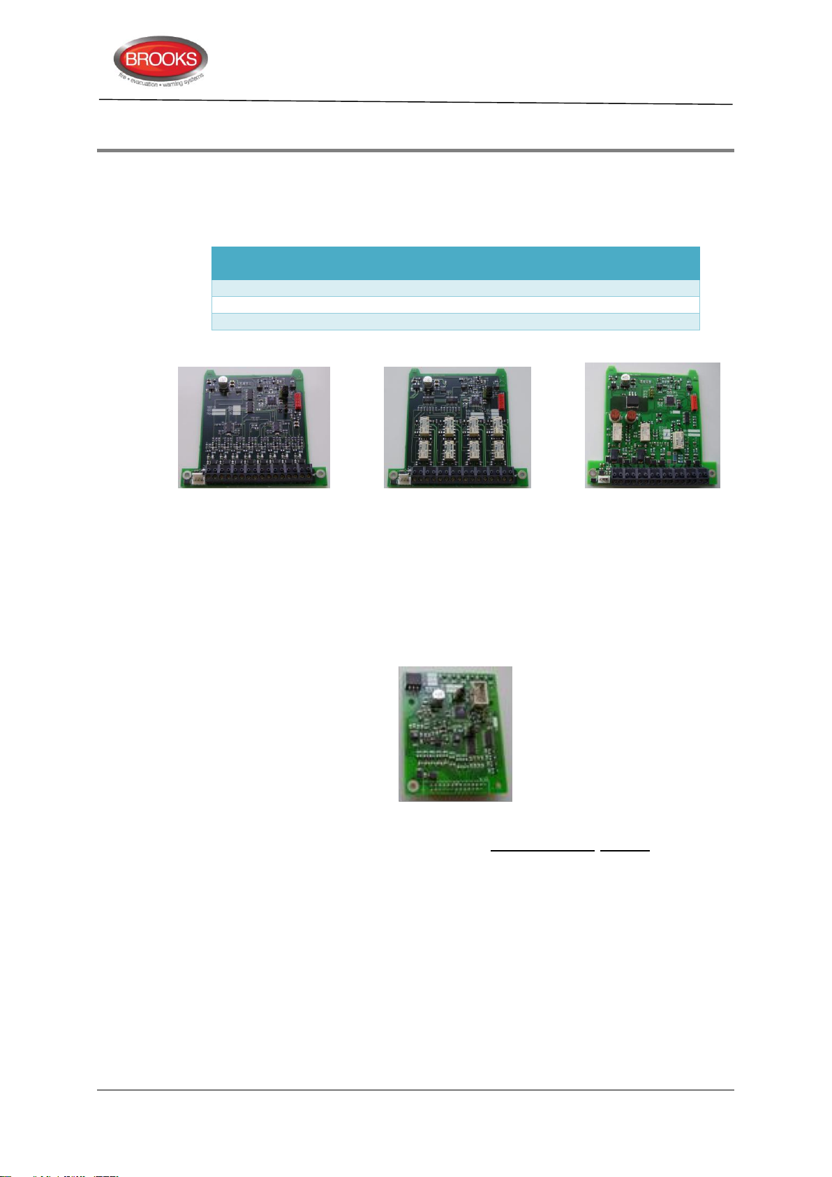
4 Expansion Boards 458X
No. of Expansion boards
(Total of any combination is 4)
Maximum Number Allowed
4580
4
4581
4
4583
4 (with warning)
Up to 4 optional expansion boards can be mounted in the FT128 cabinet on an expansion
boards holder. The total number of Expansion Boards allowed in any combination of 4580,
4581, or 4583 is 4 see Table 3 below.
Table 3 Expansion Boards Allowed
Technical / Programming Manual
FT128 Rev 2.2
Figure 3 Expansion Boards (from left to right) 4580, 4581 and 4583.
The expansion boards are mounted in an expansion board holder (Expansion boards
mounting kit 4551 or Brooks brackets) inside FT128. A supplied cable assembly is used
to connect the expansion board(s) to the main board (connector "J2" on the expansion
board and "J13" on the main board 4556). See drawings F665.
I/O Matrix board 4582 is a special type of expansion board that plugs (piggy back)
onto an Application board (Fan, Generic or Zone). The Application board is connected to
the COM loop and to 24 VDC. Up to four 4582 boards can always be used and up to eight
if no expansion boards of type 4580, 4581 or 4583 are used.
Figure 4 I/O Matrix board 4582
Each expansion board 4580-4583 must have an expansion board address (0-7) set via
jumpers on the expansion board. The jumpers "JP2-JP4" are used on boards type 4580,
4581 and 4583, and jumpers "JP1-JP3" are used on board type 4582, see Table 4 below.
EBLWin is used for all expansion boards programming.
22
Page 23
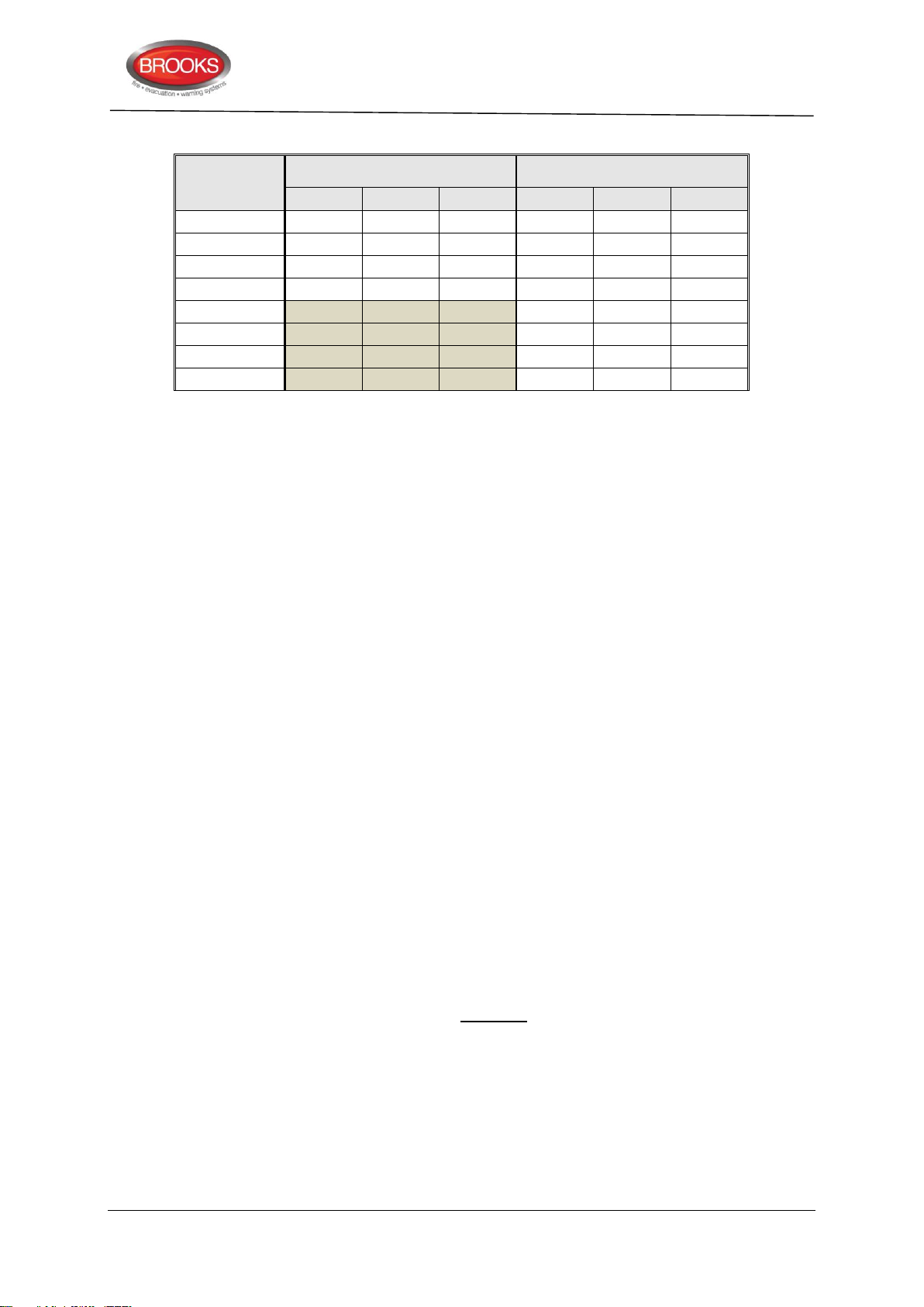
Table 4 Expansion boards address setting
Board
address
4580, 4581 and 4583
4582
JP2
JP3
JP4
JP1
JP2
JP3
0
1 X X
2 X X
3 X X X X
4 X
5 X X
6 X X
7 X X X
X=Shunted, Blank = Open
Address 4 - 7 on 4580, 4581 and 4583 are not currently used
4.1 8 Zones Expansion Board 4580
Up to four 4580 boards can be used, see Table 3 “Expansion Boards Allowed”, page 22.
Technical / Programming Manual
FT128 Rev 2.2
Each board has to be programmed via EBLWin with an address (board no.) which is set
via the jumpers "JP2 and JP4" as shown in Table 4 above.
The 4580 board has eight conventional Zone Line Inputs (0-7) intended for conventional
detectors, MCP, flow switch input or any N/O clean contact. In the last alarm point on each
zone line, an End-Of-Line device must be connected, depending on the selected "Type of
Zone Line Input", see below.
Connections to "J1:1-16" and "J2" according to drawing F665.
Each Zone Line Input has to be programmed via EBLWin for the following:
Type of Zone Line Input (see below), depending on detectors / End-Of-Line device
(capacitor or resistor), i.e. different threshold levels etc.
Alarm at short circuit i.e. whether a short- circuit on the zone line generates a fault
or fire alarm.
Zone number (Address optional)
AVF (Alarm Verification Facility), if required
Text (Alarm text when required)
Alert annunciation & time channel
Disablement & time channel
The terminals support a wire size up to 1.2 mm2.
4.1.1 Type of Zone Line Input
4.1.1.1 Zone Line Input (EOL Capacitor)
Each input must be selected either as Not used or as one of the following types / modes.
This mode should normally be used. It has the lowest zone line current consumption since
the End-Of-Line device is a capacitor, 470 nF (±10 %).
Maximum allowed cable resistance is 50 Ω.
Maximum allowed cable capacitance is 50 nF.
Maximum allowed zone line current consumption is 1.5 mA.
23
Page 24
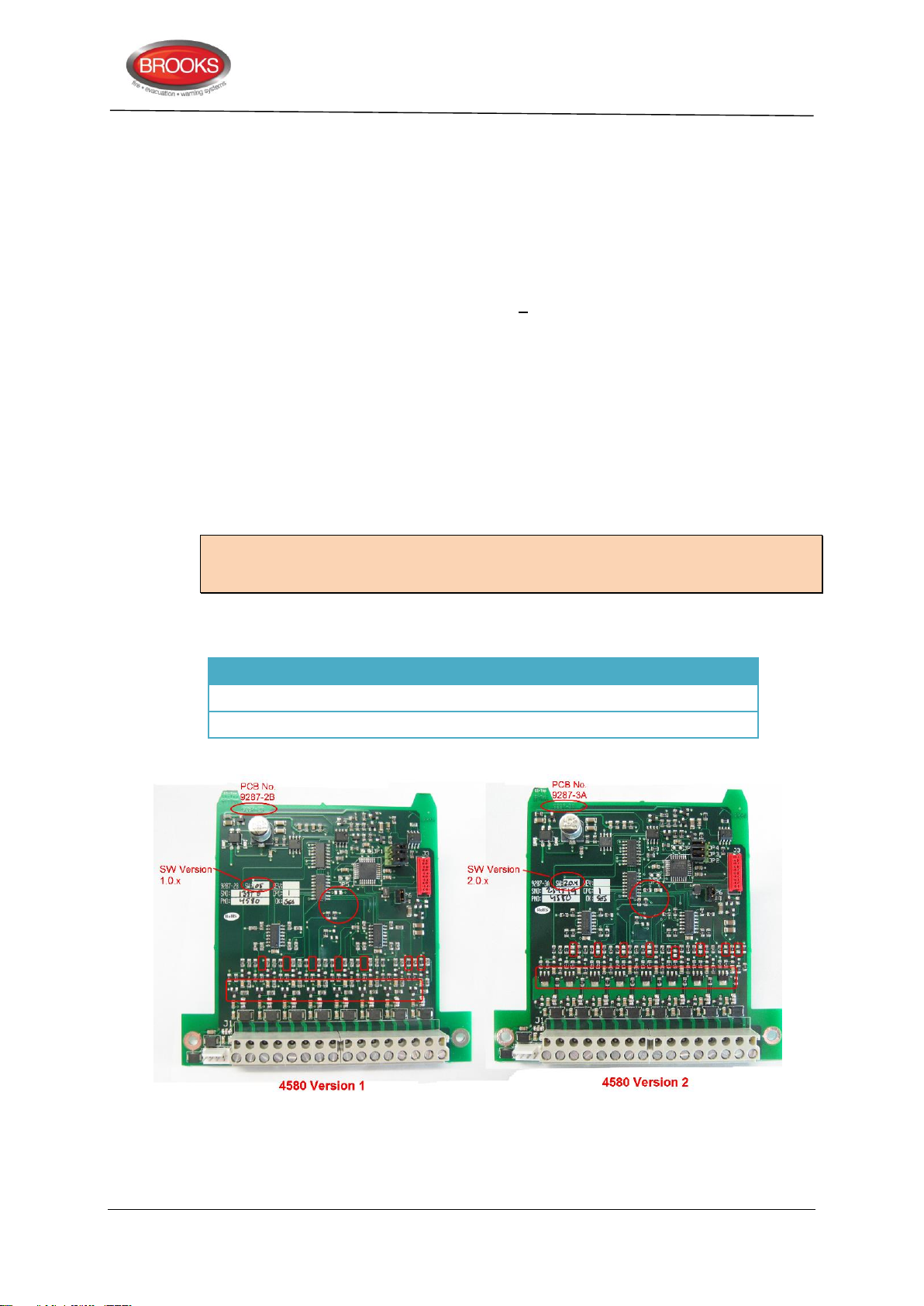
4.1.1.2 Ex Zone Line Input (EOL Resistor)
4580
SW Version
EOL Resistor to Use
Version 1
9287-2B
1.0.x
10KΩ
Version 2
9287-3A
2.0.x
4K7Ω
This mode must be used when the zone input is intended to be connected to intrinsically
safe devices e.g. intrinsically safe detectors or manual call points via the Galvanic isolator
MTL5061 (2820). The End-Of-Line device is a resistor, 10K (±5 %) with a body surface
area > 230 mm2 (supplied with Galvanic isolator).
Max. allowed cable resistance is 40 ohm.
Max. allowed cable capacitance is 70 nF.
Total zone line current consumption is < 1.0 mA.
4.1.1.3 Zone Line Input (EOL Resistor)
This mode is typically used in New Zealand where only EOL resistors are allowed. It has
to be used when any of the other types cannot be used (e.g. for some older type of
detectors and not Panasonic detectors). The EOL resistor has the highest zone line current
consumption since the End-Of-Line device is a resistor, 4K7 (±5 %).
Maximum allowed cable resistance is 50 ohm.
Maximum allowed zone line current consumption is 2.0 mA.
Technical / Programming Manual
FT128 Rev 2.2
Note: Older version of 4580 boards PCB9287-2B requires 10K End-Of-Line resistor while
the newer version PCB9287-3A requires 4K7. Table 5 and Figure 5 illustrate the two
distinctive differences between the two PCB versions in both hardware and software.
Table 5 4580 Versions with EOL Values to Use
4.1.2 Input States
Figure 5 Expansion Board 4580 Top Side Differences
Each input will be in one of six different states.
24
Page 25

4.1.2.1 Normal State
20
20
21
22
23
Technical / Programming Manual
FT128 Rev 2.2
This is the normal Zone Line Input state, i.e. no alarm, no fault, etc. and the nominal voltage
is 24 V
. From this state any other state can be reached / activated.
DC
4.1.2.2 High Current State
The maximum current consumption limit21 for the Zone Line Input is exceeded, which is
indicating that e.g. too many alarm points are connected. This generates a fault condition
in FT128. From this state any other state can be reached / activated except the open circuit
state.
4.1.2.3 Alarm State
An alarm point (or more) on the zone line is in alarm state and the alarm limit21 for the zone
line is exceeded, which activates fire alarm in FT128. In this state, the short circuit, open
circuit, high current and low voltage states cannot be reached / activated. After the alarm
reset, the Zone Line Input will return to the normal state.
4.1.2.4 Short-Circuit State
The short circuit current limit21 is exceeded, indicating short-circuit on the zone line, which
normally generates a fault condition in FT128 but instead, a fire alarm can be activated, if
this option is selected via EBLWin.
4.1.2.5 Open Circuit State
The open circuit current limit21 is passed, indicating very low zone line current consumption
or no current, i.e. the End-Of-Line device is not detected which generates a fault condition
in FT128. From this state any other state can be reached / activated.
4.1.2.6 Disconnected State
Via menu H8/S2 (Disconnect / Re-connect zone line), the Zone Line Input can be
disconnected22, i.e. there is no voltage on the zone line. From this state no other state can
be reached / activated.
4.2 8 Relays Expansion Board 4581
Up to four 4581 boards can be used, see Table 3, page 22.
Each board has to be programmed via EBLWin for an address, set via jumpers "JP2-
JP4" as shown in Table 4 page 23.
The 4581 board has eight programmable relay outputs (0-7).
Connections to "J1:1-16" and "J2" according to drawing F729.
Each output has to be programmed via EBLWin for the following:
Type, i.e. output for Control, Alarm devices, etc.
Output signal period (steady, pulse, delay, etc.)
Logic, i.e. normally open (NO) or normally closed (NC) contacts23
Control expression (one or more trigger conditions)
For more information, see chapter “Output Programming”, page 81.
Allowed voltage 15-28 VDC.
This limit is dependent on the selected input mode.
This is indicated in FT128 by the LED "Disablements".
Relay contact ratings: Max. 2A @ 30 VDC.
25
Page 26

Technical / Programming Manual
24
25
The terminals support a wire size up to 1.13 mm2 (1.2 mm).
4.3 Inputs and Outputs Expansion Board 4583
Since the maximum current consumption for this type of boards can be up to 400 mA, only
two boards should be used however, up to four boards (V2.1.x and higher) can be
configured with a warning if more than two are used when the SSD is validated in EBLWin,
used.
Note: If more than two 4583 boards are used, care must be taken not to overload the
fuse on the main board (fuse F5)
Each board has to be programmed via EBLWin for an address set via the jumpers "JP2JP4", see Table 4 page 23.
The I/O expansion board 4583 has two programmable supervised / non-supervised voltage
outputs (Output 0-1), one special programmable output (Output 2) intended for German
extinguishing system and five programmable supervised or non-supervised inputs (Input
0-4).
Connections to "J1:1-16" and "J2" according to drawing F731.
Outputs 0-1 has to be programmed via EBLWin for the following:
Type of output, i.e. output for Control, Alarm devices, etc.
FT128 Rev 2.2
Output signal period (steady, pulse, delay, etc.)
Supervised / Non-supervised24
Logic, i.e. normally low (default) or normally high (24 VDC)25.
Control expression (containing one or more trigger conditions)
One to five 33K resistors can be connected. When all connections are completed, perform
a "Calibration of supervised outputs (menu H5/A1)". Calibration value has to be in the range
4K7-50KΩ. See also the FT128 Operation Manual chapter "Calibration of supervised
outputs (menu H5/A1)".
Voltage Output 0 (J1:1-2): maximum 200 mA (Fuse F1).
Voltage Output 1 (J1:5-6): maximum 200 mA (Fuse F2).
See also Section “Programmable outputs”, page 77.
Output 2 has to be programmed via EBLWin for the following:
Type, i.e. output for Control, Alarm devices, etc.
Output signal period (steady, pulse, delay, etc.)
Logic, i.e. normally open (default) or normally closed.
Control expression (containing one or more trigger conditions)
Output 2 (J1:11-12): Normally Open (high resistance, 3K3) or Normally Closed (low
resistance, 680R). See drawing F731
See also Section “Programmable Outputs”, page 77.
Input 0-4 have to be programmed via EBLWin for the following:
Trigger condition (triggered by)
Supervised / Non-supervised
Logic, i.e. Normally open (high resistance, 3K3, when supervised)
A normally high output cannot be supervised. The supervision voltage is 1.5 – 3.7 VDC (depending on the number of supervision
resistors) and the polarity is reversed compared to an activated output.
Regarding system voltage, see Table 1, page 15
26
Page 27
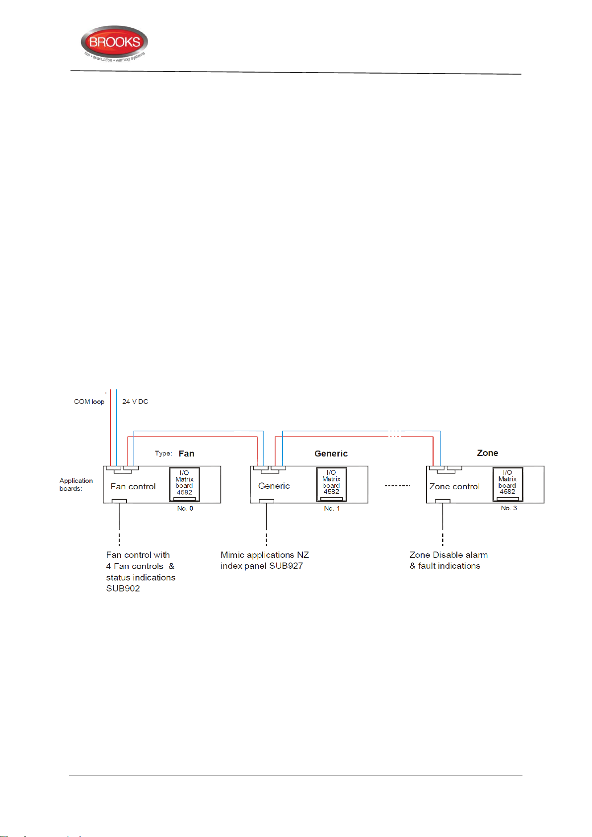
or Normally Closed (low resistance, 680R, when supervised)
FT128 CIE
SUB900
Additional information depending on the selected type
Input 0 (J1:3-4)
Input 1 (J1:7-8)
Input 2 (J1:9-10)
Input 3 (J1:13-14)
Input 4 (J1:15-16)
See also chapter “Programmable Inputs”, page 71.
4.4 I/O Matrix Board 4582
The I/O matrix is a special type of expansion boards, it can only be used in conjunction with
an Application Board. Three types of application boards are available; AS1668 Fan
control, Zone control and NZ Generic mimic for index panels, see Figure 6 below.
The I/O Matrix board (80 x 63 mm) is plugged into the Application board ("piggy back"
connection) and has 16 switch inputs and 48 LED outputs which can be individually
programmed (generic application only). The COM loop and 24 VDC is connected to the
Application board.
Technical / Programming Manual
FT128 Rev 2.2
Figure 6 I/O Matrix Board Application Overview
27
Page 28
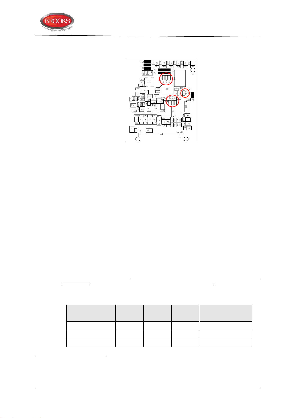
4.4.1 I/O Matrix jumper link setting:
Type (mode)
Application Board
JP4
JP5
JP6
Brooks Application
Board Part No.
Fan Control
SUB902
Zone Control
X
SUB900
Generic27
X
SUB985-SUB98828
26
27
28
Figure 7 I/O Matrix PCB layout
The PCB layout of the I/O matrix board is shown in Figure 7, jumper links are shown in red
circle. Ensure that JP7 is not fitted, this is used for production purposes only. Three
different options for the Application Board Types can be selected via jumpers (JP4 &
JP5) on the I/O Matrix board as shown in Table 6 below.
Technical / Programming Manual
FT128 Rev 2.2
There are no COM loop addresses to be set. Instead, the Expansion Board No. / Address
(0-7) is set with jumpers (JP1-JP3) on the I/O Matrix board. See Table 4, page 23.
The three configuration options for the I/O matrix board are:
Generic, normally used for any special applications e.g. NZ index panel, mimic or
relay boards, pump status indications, etc. Maximum of two generic options can be
used, if no zone control is used.
Fan Control, up to 8 fan modules can be used if no other applications or expansion
boards used or 4 modules if the permitted quantity of generic and zone control are
used. 4 fans are the maximum number allowed module.
Zone Control, only 2 zone options can be selected to provide a maximum of 16
zones26 for each FT128 system, if no generic option is used.
Up to four I/O Matrix boards can be used and up to eight if no expansion boards type 4580,
4581 and 4583 are used but maximum two I/O Matrix boards of type Generic and type
Zone control i.e. 2 zone control or 2 generic or a combination of both.
In FT128, total of up to 200 outputs can be used, including all types of outputs.
Table 6 I/O Matrix board 4582 type setting
Due to the space limitation, only 12 zones are available in every zone control module
When SUB900 or SUB902 is used as a Generic application board, the Type of Inputs and Outputs can be customised by
programming in the EBLWin configuration software.
The new versions of NZ mimic boards SUB985, SUB986, SUB987 & SUB988 replace the discontinued SUB927 and SUB927R,
for more details refer to chapter “New mimic options” page 39
28
Page 29
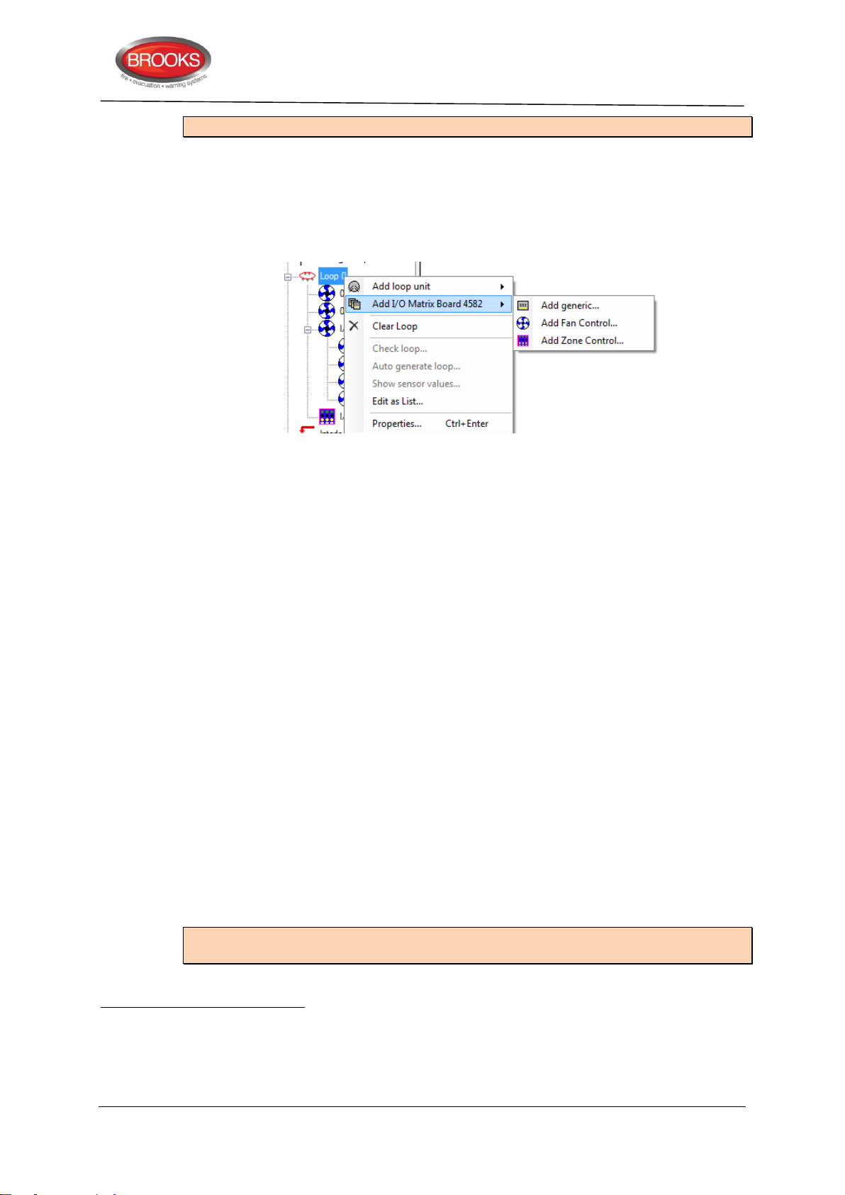
Technical / Programming Manual
29
30
31
FT128 Rev 2.2
Note: Jumper “JP6” is for future use.
Each I/O Matrix board has to be programmed via EBLWin according to its application.
Set the address on the 4582 via jumpers "JP1-JP3", see Table 4 page 23.
Right click on the loop and select “Add I/O Matrix Board 4582” to bring up the
context menu to select the type of Application Board to be added as shown below:
....and programmed for the following:
Address (must be the same board no. as set via jumpers "JP1-JP3").
Name (I/O Matrix Board # - normally not changed)
LED test on Input 15 (selected or not selected)
4.5 FT128 External Termination
In the Australian convention, the FT128 main board 4556 is mounted on the rear of the
front door. In order to avoid the field wiring termination on the swing door, an adapter board
SUB836 29 is added to the main board. The new version of the adapter board is plugged in
the screw terminals of the main board 4556 and interfaced to another external termination
board SUB835 mounted on the equipment plate. The adapter board SUB836 is connected
to the termination board SUB835 via ribbon cable.
The FT128 has only one programmable relay output. To increase the number of
programmable relays in the standard FT128 system, another relay with two changeover
contacts has been added to the termination board to provide 2 sets of additional relay
contacts30. This relay is controlled by the “Voltage output S1” 31 e.g. if S1 is programmed
for general alarm, the following will be available:
Voltage output S1 on CON 8
Change over alarm contacts R2-1 on CON 5
Change over alarm contacts R2-2 on CON 4
The PCB physical layout of the adapter board SUB836 is shown in Figure 8.
The PCB physical layout of the external termination board SUB935 is shown in Figure 9.
Note: As shown in Figure 8 and Figure 9, one physical PCB is used for both boards but
different components are fitted in each one.
The adapter board shown in Figure 8 and external termination board shown in Figure 9 use a new PCB revision (PCB250 Rev
5). In all previous revisions, the adapter board is soldered in the terminals of FT128 main board (4556) but the new PCB
revision has pins to screw in the terminal block on FT128 main board.
The additional alarm contacts can be used to trigger the OWS or for any other application.
The voltage output S1 terminals are still available on the termination board SUB835, please note, the current limitation of S1
is less than 200mA.
29
Page 30
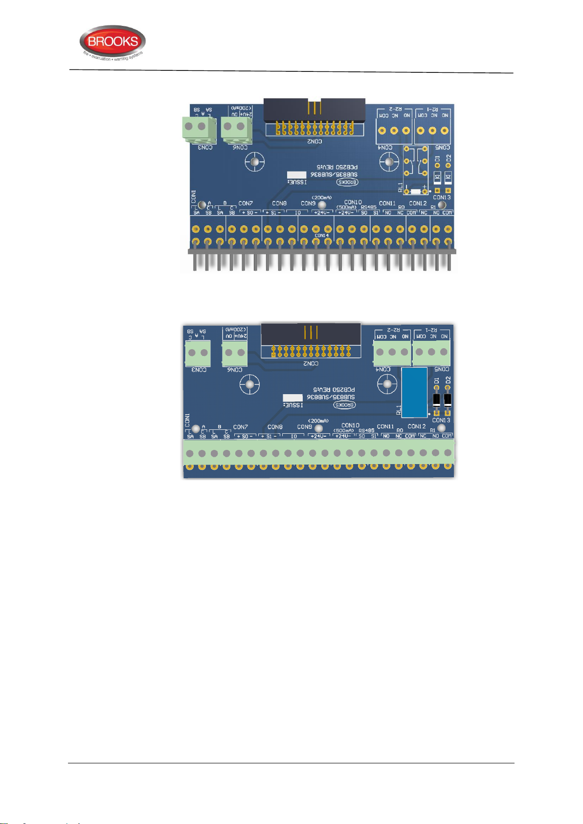
Technical / Programming Manual
FT128 Rev 2.2
Figure 8 SUB836 Adaptor Board
Figure 9 SUB835 external Terminal Board
The adapter board SUB836 provides additional terminals to support connections from COM
loop SA & SB (CON 3) and 24V (CON 6) to I/O matrix boards 4582 mounted on the rear of
the front door.
The external termination board SUB835, as shown in Figure 9, provides two additional
alarm relay contacts R2-1 and R2-2 (CON 5 & CON 4), current rating for the contacts is 2A
@ 30V dc. The SUB835 provides additional terminals as well, for the COM loop and 24V
dc, these terminals can be utilised for modules mounted on the equipment plate and
requiring COM loop connections or 24VDC.
30
Page 31

5 Optional Modules
32
32
5.1 AS1668 Fan Control
Used for Application board type Fan control (SUB902) which has a front decal label to
indicate and control of up to four fans. Typical fan control front is shown in Figure 12 page
36.
Each fan control module consists of a universal I/O matrix 4582 specifically configured for
fan control applications and application board SUB902. Different Programming options are
simplified through the EBLWin configuration software.
Each fan control module has controls and fan status indicators for 4 fans. Each fan status
is indicated by six LEDs (On / Auto / Off / Running / Stopped / Fault) and controlled via
three push buttons (On / Auto / Off). One "Fan Reset" button is provided in every AS1668
fan module. A LED test button is also provided to test LED’s for each fan module (if
programmed).
Technical / Programming Manual
FT128 Rev 2.2
In EBLWin, the functionality of the fan control relays Re0 & Re1 in “3361 for fan” module
has been improved
programmer to configure Re0 and Re1 independently i.e. start relay and stop relay are now
configured separately. The monitored input In0 is in use when the fan is only controlled
from the CIE. External control from Mechanical Services Switch Board (MSSB) or via time
clock will indicate the fan status without generating a fan fault.
5.1.1 Mode Control
The buttons / LEDs On, Auto and Off are used to manually override the fan mode of
operation. The switches are non-latching and the mode of operation will be indicated by
the corresponding LEDs.
On: Fan is running in manual override mode independent of the fire mode in the CIE
or any external control e.g. MSSB. “On” and “Fan Running” LED’s are lit. “On”
control has higher priority over alarm and external control.
Auto: Fan either be running or stopped depending on the CIE alarm condition. The
fan may also be controlled externally (less priority than alarm) from mechanical
services e.g. time clock. LED “Auto” is lit and either “Fan Running” LED or “Fan
Stopped” LED is also lit. The “Auto” LED flashes during the time that the fan is
changing status (running to stopped or stopped to running) then becomes
steady.
Off: Fan is stopped in manual override mode independent of any alarm condition in
the CIE. “Off” and “Fan Stopped” LED’s are lit. “Off” control has the highest
priority over alarm or external control.
. New “Enhanced mode” is added to 3361 configuration to enable the
5.1.2 Fan Status
Running Indicates fan running, red
Stopped Indicates fan stopped, green
Fault Indicates fan fault, yellow
The fan fault LED is lit if the control from the CIE to change the fan status (via
3361 relay contacts) is not verified via input In0. The request to change the fan
status from the CIE can be due to one of the following:
1. Manual operation of the manual override switch (On or Off) for a fan or
In Win128, the two relays Re0 and Re1 have toggle action i.e. cannot be controlled independently, both activated at the same
time but with different contacts (Re0 is normally open & Re1 is normally closed).
31
Page 32
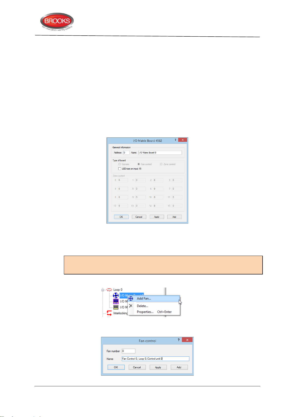
2. In Auto mode, a fire alarm that controls the fan is activated.
In both cases, if the feedback signal confirming the change of state has not
been received by input In0 in 3361 within 30 seconds (default), the fan fault LED
will be lit.
If In0 is configured to be supervised and there is an open circuit fault in the input
wiring, the fan fault LED will also be lit.
Each Fan (0-3) (i.e. each Fan control) has to be added and programmed via EBLWin.
5.1.3 Configuration and Programming
For each fan, a field module (3361) is required and has to be configured in EBLWin as
“3361 I/O unit for fan control”. The AS1668 fans can be configured as follow:
1. Right click on the COM loop and “Add I/O matrix board 4582”, the following dialog box
appears:
Technical / Programming Manual
FT128 Rev 2.2
Select the I/O matrix board address (0-5) and change the name to “AS1668 Fan
Control”. If the LED test function is required, mark the check box “LED test on
input 15”.
Note: The address selected in EBLWin (0-3) must match the address of the I/O matrix
board which is set by the jumpers JP1-JP3 as per Table 4 page 23. The type of board is
automatically selected.
2. Right click on the configured “I/O Matrix Board” and select “Add Fan” as shown below
3. The Fan control dialog box appears for the 1st fan to be added. Repeat adding fans as
required, maximum 4 fans (0-3).
32
Page 33
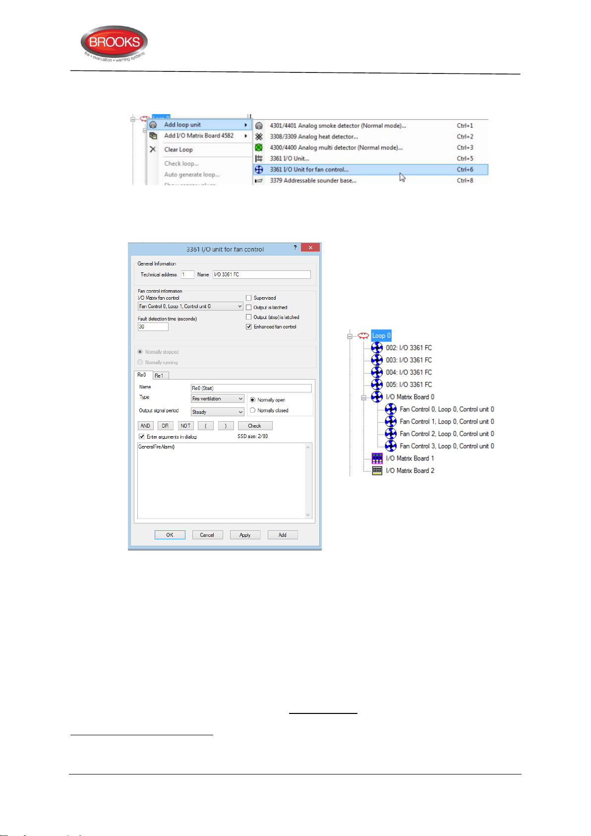
Technical / Programming Manual
33
34
33
34
FT128 Rev 2.2
4. For each added fan, a “3361 I/O Unit for fan control…” must also be added. To do this,
right click on the COM Loop to Add loop unit and choose “3361 I/O Unit for fan control..”
5. When the 3361 dialog box appears, select from the pull down menu under the Fan
control information area, one of the fans that was added in the previous steps as shown
below. The final tree view should look like the right side as shown below.
6. On the 3361 properties shown above, select the required configuration as follow:
Select whether In0 required to be supervised or non-supervised.
Relay output Re0 and Re1 output to be latched or non-latched.
Enhanced mode
Write the logical expression for Re0 and Re1 (enhanced mode only
for independent configuration of Re0 and Re1.
).
Fault detection time is set to 30 seconds by default, change time if required.
Select Re0 and/or Re1 type “Fire ventilation” (default).
If a supply air fan is to be configured, on the “Output signal period” on Re0 and/or
Re1 dropdown menu select “Supply Air Fan” as shown in step 7.
In non-enhanced mode, if Re0 is normally open, Re1 will automatically be normally closed and vice versa. If "Enhanced fan
control” function is selected, Re0 and Re1 tabs will be available for individual programming.
In non-enhanced mode, only Re0 requires logical expression hence Re1 will follow same logical expression.
33
Page 34
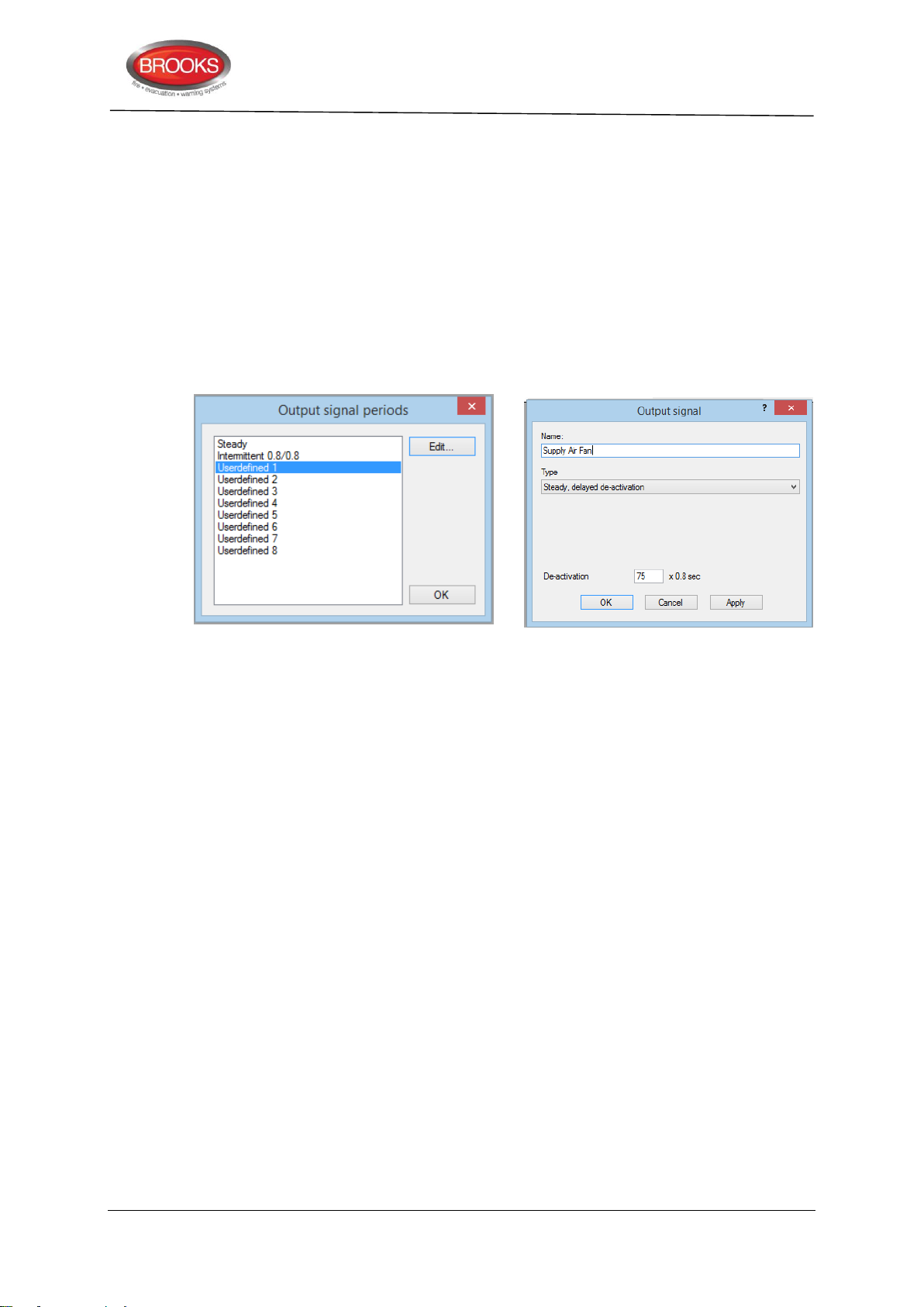
Technical / Programming Manual
FT128 Rev 2.2
7. For supply air fan applications, set the post timing required to reset the duct detector
as follow:
On the “System” tab, select “Output signal period”.
In the displayed dialog box shown below, select one of the “Undefined” options
Re-name the “Undefined” to Supply Air Fan then click edit.
On the drop down menu, select “Steady, delayed de-activation”
In the de-activation box, enter 75, this will set the post timing of the duct smoke
detector to 60 seconds i.e. the duct detector will reset after 60 seconds of clearing
up the smoke.
Click ok.
5.1.4 Fan Reset
A fan reset button is added to the front display of the fan control module to comply with the
requirements of AS1668.2 and used to independently reset 3361 relays Re0 and Re1 in
fire mode conditions. The two relays should be programmed in EBLWin to be “Latched” i.e.
resetting the alarm in the CIE will not bring the fans to the non-alarm condition until the
reset button is pressed. If the alarm remains active in the CIE, the fan reset button will not
function.
5.1.5 Fan Front Display
The fan control and display module is normally mounted in the CIE but it is also possible
to remotely install the module and connect it to the COM loop and 24V supply. The fan
operation is controlled by Re0 and Re1 relay outputs on the 3361 unit. The feedback signal
from the fan pressure switch is connected to the supervised input of 3361 to provide the
required indications of the fan status.
The typical front display of AS1668 module and connection diagram are shown in Figure
12, page 36.
Two typical fan application examples are shown in the following sections.
5.1.6 Supply Air Fan
A supply air fan is normally running in the non-fire mode condition and stops when smoke
is detected in the air supply duct, timing sequence is shown in Figure 10 below.
34
Page 35
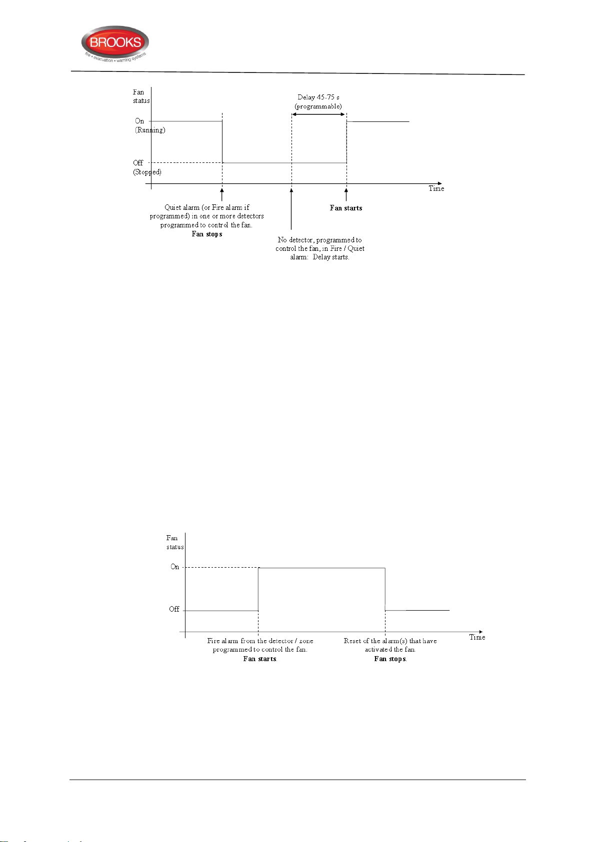
Technical / Programming Manual
FT128 Rev 2.2
Figure 10 Supply Air Fan Timing Sequence
When the smoke is no longer present in the supply air duct, a time delay (45-75 seconds)
starts, the fan remains in the shutdown mode until the time delay is elapsed, then the duct
detector resets and causes the fan to restart. The presence of smoke in the supply air does
not initiate a Fire Brigade TX signal or any other alarm output (type, quiet alarm). The
Occupant Warning System does not sound. Only the “FIRE’ and general alarm indicators
will be flashing and a quiet alarm message displayed.
Notes related to supply air fan applications:
1. Only analogue smoke detectors can be used in supply air fan applications.
2. The detector used in supply air fan applications must be selected as a “Quiet
Alarm” i.e. check box in EBLWin program is ticked.
3. One detector, several detectors or a zone can be programmed to control the
supply air fan.
4. A time signal period output must be configured in EBLWin as shown in section
5.1.3 step 6 to set up the post timing which normally is 60 seconds.
5.1.7 Smoke Exhaust / Spill Fan
Figure 11 Smoke Exhaust Or Spill Fan Timing
The smoke exhaust fan is normally controlled by general alarm, single device or a zone.
Both analogue detectors and conventional zones can be configured to control the fan.
Standard time signal period output can be used.
Typical AS1668 fan example is shown in Figure 12 below
35
Page 36
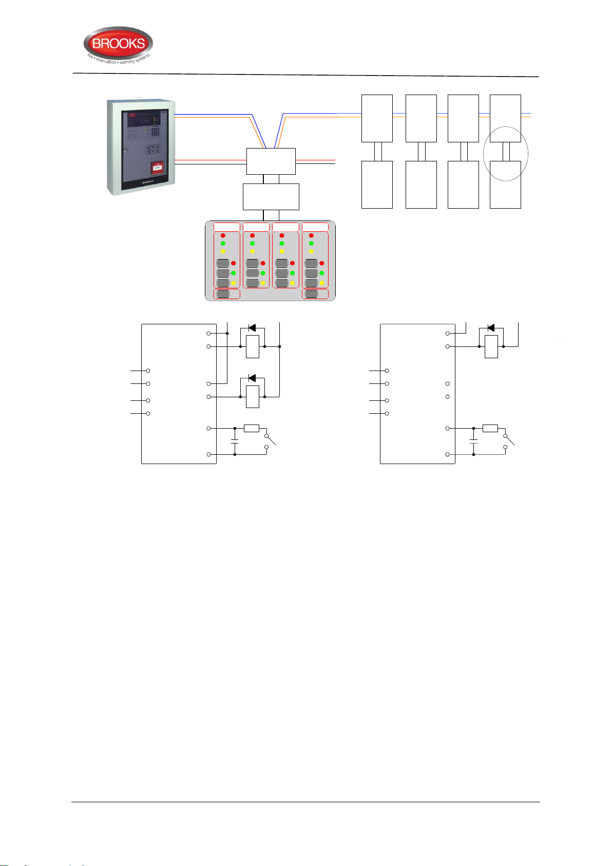
Technical / Programming Manual
COM COM
N/O N/O
N/O N/O
COM COM
LOO P IN LOO P IN
LOO P OUT LOO P OUT
Re0 Re0
Re1 Re1
Z Z
0V 0V
MO NITOR E D
IN P UT
MO NITOR E D
IN P UT
FAN STO P
RELAY
FAN STA R T
RELAY
RL1 RL1
RL2
E OL
CAP
E OL
CAP
470n 470n
470R 470R
I/O MODULE
3361
I/O MODULE
3361
24V D C / A C 24V D C / A C
STANDARD MODE
FAN STA R T / S TO P
RELAY
P RES. S W ITC H OR C T
FAN STA TU S
P RES. S W ITC H OR C T
FAN STA TU S
ENHANCED MODE
I/O Matrix
board
COM loop
24VDC
3361
Fan
3361
Fan
3361
Fan
3361
Fan
Fan control
board
or 24VDC from
external source
FaultFault Fault Fault
RunningRunning Running Running
Stopped Stopped Stopped
FF F F
AA A A
NN N N
On OnOnOn
Auto AutoAutoAuto
Off OffOffOff
Fan
Reset
LED
Test
Stopped
1668 FAN CONTROL
FT128 Rev 2.2
Figure 12 AS1668 Fan Control Example
36
Page 37
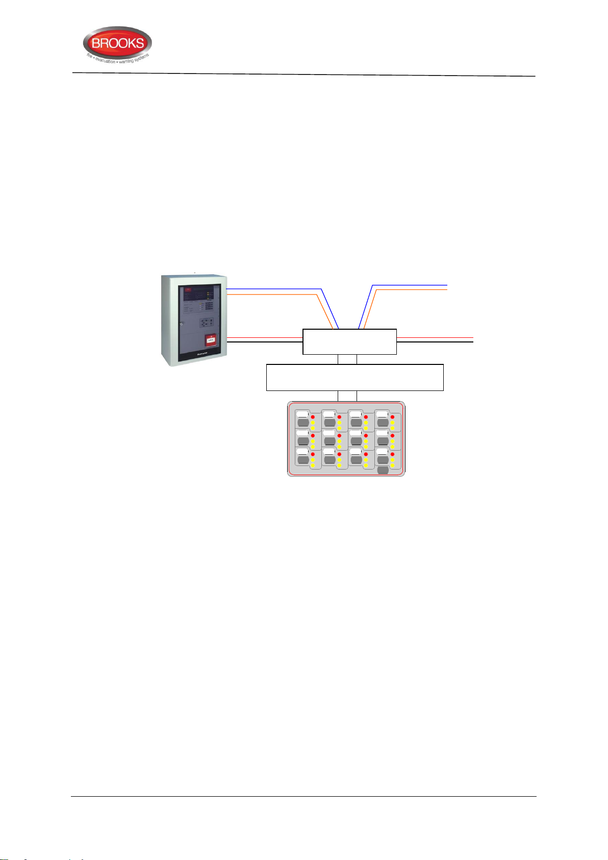
5.2 Zone Control
or 24VDC from
external source
COM Loop
24VDC
Zone Control & indicating board
SUB900
I/O Matrix Board
4582
Disable DisableDisableDisable
Disable DisableDisableDisable
Disable DisableDisableDisable
LED
Test
DS DSDSDS
DS DSDSDS
DS DSDSDS
AL ALALAL
AL ALALAL
AL ALALAL
FT FTFTFT
FT FTFTFT
FT FTFTFT
ZONE CONTROL
The Zone Control Module provides a simplified indication of zone status without the need
for a liquid crystal display. The disable controls allow a specific zone to be temporarily
disabled without the need to access the CIE menu. This is typically used where building
works or maintenance procedures are being carried out in a localised area of a building.
The front display layout is shown as part of Figure 13 below.
Only two zone control modules can be used in FT128, if no generic applications are used.
Each zone control module consists of a universal I/O matrix 4582 plugged in a display
board SUB900 specifically configured to provide up to 12 individual zone indicators and
controls. The module is normally mounted in the CIE. but it is also possible to connect the
module remotely via the COM loop and 24VDC supply.
Technical / Programming Manual
FT128 Rev 2.2
Figure 13 Zone control application
5.2.1 Controls & Indications
Alarm LED (Red) – Illuminates when an alarm from a conventional zone, an addressable
device or group of addressable devices designated as a zone enters into an alarm state.
Fault LED (Amber) – Illuminates when either a short circuit or open circuit fault on a
conventional zone input or any fault that prevents an addressable alarm point in a
designated zone to operate properly.
Disabled LED (Amber) – Illuminates when a zone is disabled either by the disable switch
on the zone control card or where the zone is disabled via menu H2/B1.
5.2.2 Zone Control Configuration
Disable Switch – Pressing the disable switch will disable the specific zone selected.
Pressing the switch a second time will re-enable the zone. Functions are the same as menu
H2/B1.
LED Test Switch – Pressing the LED test switch illuminates all indicators if input 15 is
selected when programming the zone control function.
When the I/O Matrix board is selected in EBLWin to “Zone Control” type, up to 16 zones
[0-15] can be configured. The display Board is limited to only 12 zones and one additional
switch for LED test. The following procedures are used to configure the zone control
module:
37
Page 38
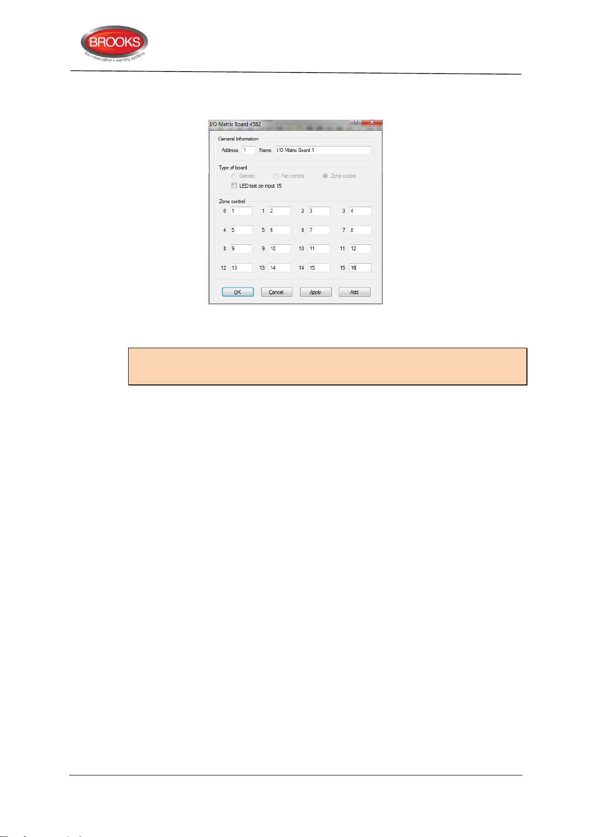
Technical / Programming Manual
FT128 Rev 2.2
1. Right click on the COM loop and “Add I/O matrix board 4582” then select “Add zone
control”. The following dialog box will be showing.
2. Select the zone control module address (0-3) and zone control name (if required). If
the LED test function is required on input 15, tick the check box.
Note: The address selected in EBLWin (0-3) must match the address of the I/O matrix
board which is set by the jumpers JP1-JP3 as per Table 4 page 23. The type of board is
automatically selected.
3. Select the check box “LED test on Input 15” if this button is to be used for LED tests or
uncheck the box if LED test facility is not required.
4. Assign the zone number in the corresponding Zone control boxes.
5. Click OK.
5.3 Generic Applications
5.3.1 Overview
The generic feature in the FT128 software supports the remote mimic applications of the
I/O matrix board 4582. Currently, this feature is used in the New Zealand Fire Brigade
mimic and index panels as well as other products. This section describes one of the main
applications of the generic option, the popular NZ index panel. Refer to Brooks technical
datasheet TDS019 for other applications.
Each NZ master mimic board provides 12 LED indications and screw terminals for 4 inputs
(switches). The first 3 LEDs used for Common alarm (red), Normal (green) and Defect
(yellow). The remainder 9 LEDs (red) used to indicate separate zone indications or sprinkler
flow switch indication. Two of the four inputs are used to interface the NZ Fire Brigade
bulgin keys to the CIE. Additional slave mimic boards can be added to provide up to 36
additional red LED indicators.
Up to 4 mimic boards can be used to indicate maximum of 48 individual zone indications,
only one I/O matrix is required for every 4 mimic boards, up to two I/O matrix boards can
be used in the NZ mimic applications to provide 96 LED indicators, if no zone control
modules are used. Refer to drawing F702A for connection diagram. A typical NZ mimic
application is shown in Figure 15 below.
38
Page 39
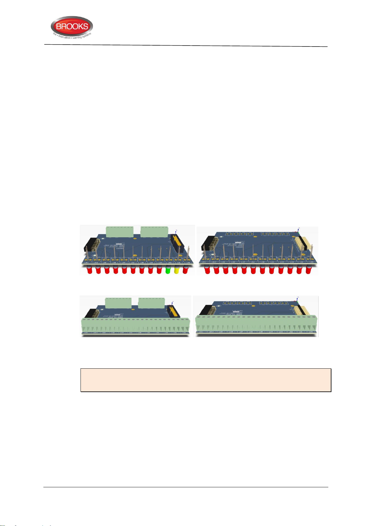
5.3.2 New mimic options
The new design of the mimic boards allows for either LED indicators or screw terminals for
graphic or remote LED’s. Four new boards are now available as shown in Figure 14 below:
1. Master LED mimic Board SUB985: This must be the first board and to be fitted
with the I/O matrix board 4582. The boards contains the first 3 common indicators
and additional 9 red indicators. It also contain terminals to connect the Bulgin keys.
All outputs / inputs are fully programmable.
2. Slave LED mimic board SUB986: contains 12 fully programmable red indicators,
no provision for terminals or connectors for the I/O matrix. Up to 3 slave boards
can be connected to the master board via plug-in connectors.
3. Master terminals mimic board: In addition to the connector for the I/O matrix
board and Bulgin keys terminals, it also contain terminals to connect 12 remotely
located LED’s (no on-board LED’s). The I/O matrix board is to be fitted to this
master board. The board can be utilised to connect existing LED mimics to new
FT128 in retrofit applications.
4. Slave terminals mimic board: Up to 3 slave boards can be connected to the
master board via the plug-in connectors to provide terminals for additional 36
LED’s.
Technical / Programming Manual
FT128 Rev 2.2
Master LED mimic board SUB985 Slave LED mimic board SUB986
Master Terminal mimic board SUB987 Slave terminal mimic board SUB988
Figure 14 Mimic Board Options
Note: Mounting holes of the new series of mimic boards are slightly different to the
mounting holes of the previous version (SUB927) i.e. new mimic LED boards must be
used in the new index cabinets.
5.3.3 Configuration and programming
The following procedures are used to configure the NZ mimic or index panel:
1. Select the COM loop then “Add I/O matrix board 4582” and select “Add generic”.
The following dialog box will appear.
39
Page 40
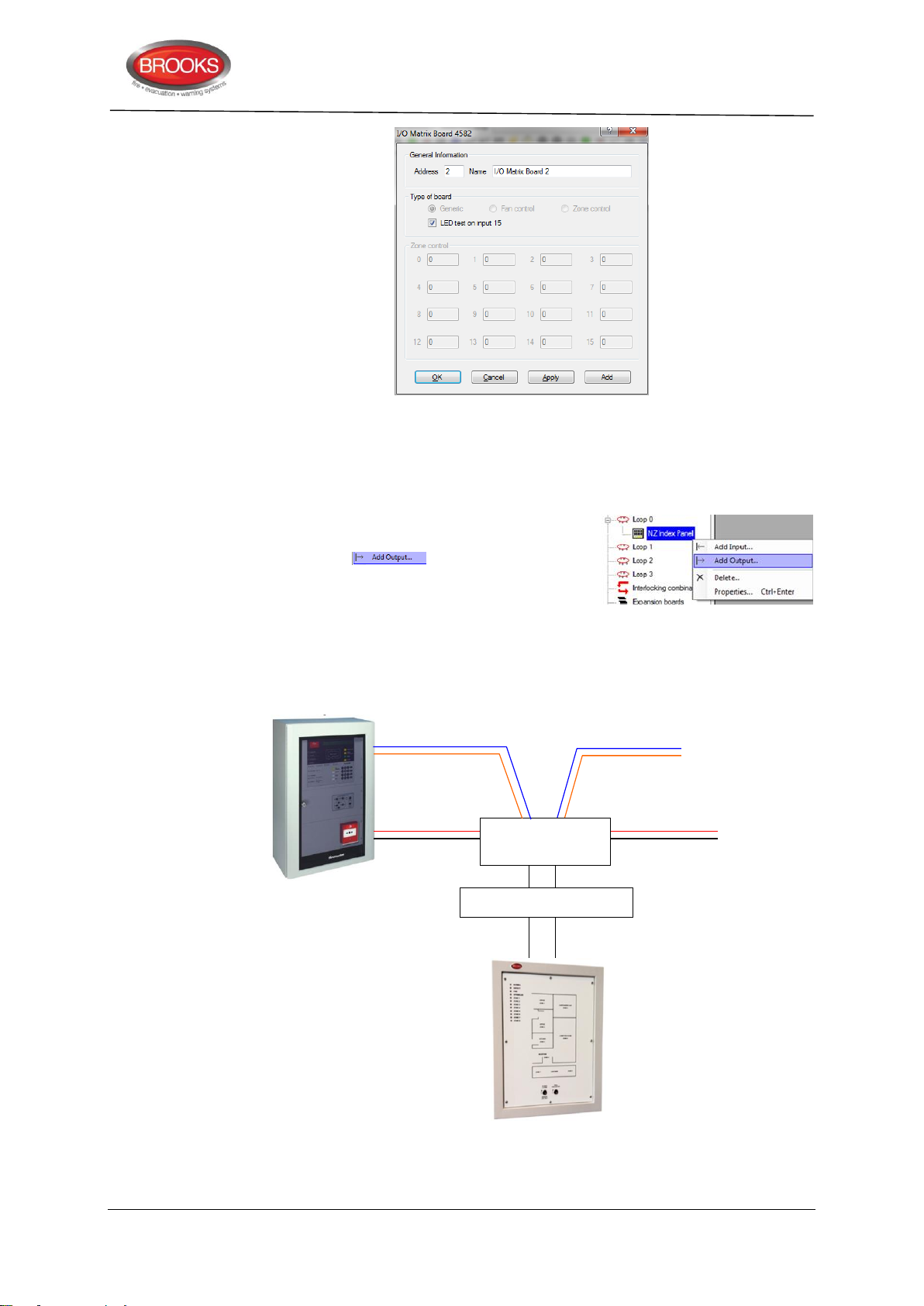
Technical / Programming Manual
or 24VDC from
external source
COM Loop
24VDC
Mimic board
I/O Matrix Board
4582
FT128 Rev 2.2
2. Enter the address (0-3) (usually automatically assigned) in the general information
area and give it an application name e.g. NZ Index panel.
3. Select the check box “LED test on Input 15” if this button is to be used for LED test
or uncheck the box if not required.
4. Right click on the Generic Board (i.e. NZ Index
Panel as a given example) that was added in step
1 and choose from the context menu
as required (0-47) and enter the fields in the
properties dialog box with its logical expression
(similar to programmable relay output).
5. Add input 0 and input 1 to program the Bulgin keys. Select type “NZ Silence switch”
for input 0 and assign the name to “Silence Alarms”. Select type “Evacuate” for
input 1 and assign the name to “Evacuate”.
Figure 15 Generic application, NZ index panel
40
Page 41
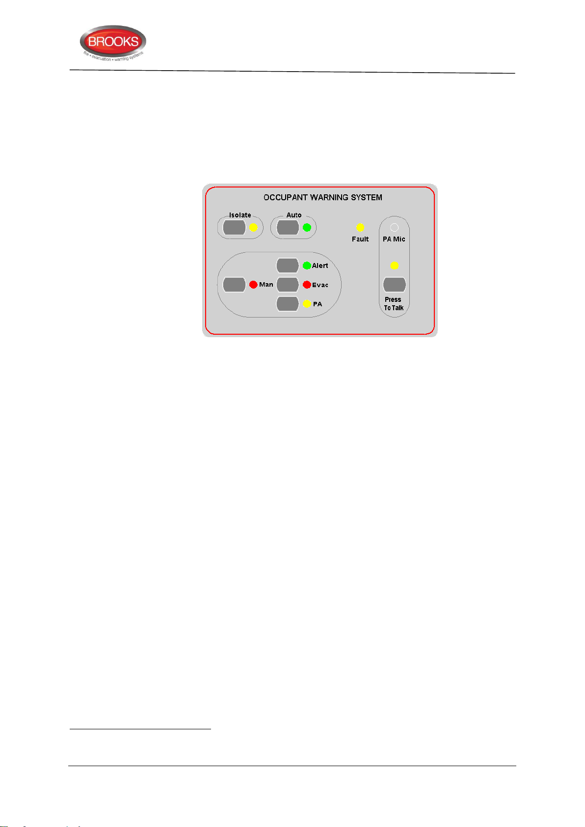
Technical / Programming Manual
36
35
36
37
5.4 Occupant Warning System (OWS)
5.4.1 Overview
Brooks OWS is an intelligent occupant warning system that can be incorporated in FT128
with number of options depending on the available space in the standard cabinet, larger
enclosures can be used to allow for more options.
FT128 Rev 2.2
Figure 16 Occupant Warning Display Module
The OWS is supplied with a wide range of high efficiency class-D audio amplifiers: 60, 120
or 250 Watts. A basic OWS system fitted in FT128 supports the following standard
Features:
Digital voice messages for alert and T3 (or AS2220 evacuation tone)35.
Supervised trigger Input (short/open circuit fault)
Supervised dual Strobe 24 VDC output for alert and evacuation strobes.
Supervised 100V speaker line output (open/short circuit fault).
Fault Relay output (changeover contacts)
Fault indicators for strobe output, trigger input and speaker circuit on OWS main
board. Only one common fault indicator on the front display.
Built in electret microphone.
Auxiliary input to connect to Brooks single or multiple zone remote microphones
Auxiliary audio enable/disable switch input.
An optional expansion 4 zone splitter board can be fitted with the standard OWS, maximum
of 4 boards can be used to provide up to 16 fully supervised speaker zone circuits.
The four zone splitter boards can be used to individually select one of the four zones (or all
zones) for PA announcement purposes only37. The PA front display can select up to 8 PA
zones and requires 2 x 4 zone splitter board.
5.4.2 Audio Amplifiers
60 Watt audio amplifier SUB865
120 Watt audio amplifier SUB866
250 Watt audio amplifier SUB867
In NZ applications, the OWS has to be configured to provide AS2220 tones and voice messages.
OWS faults are hardwired via this common fault relay to input I0 in FT128 to display OWS fault on the LCD.
The tone / message is common for all zones, only PA can select one or multiple zones for announcement.
41
Page 42
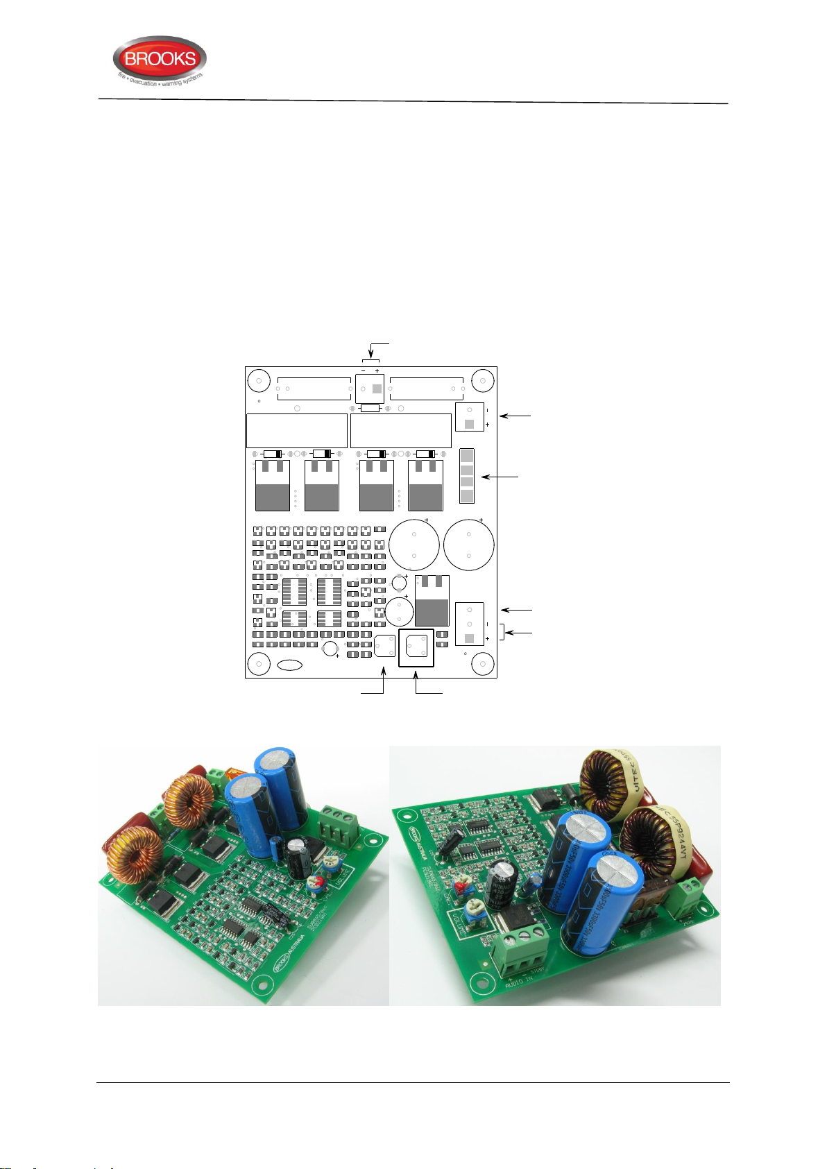
Due to the limited current capability of FT128 power supply, the OWS requires separate
AUDIO O UT
AUD IO IN
CAL.
STDBY
PCB218R1
SUB865/SUB866
(TX SEC)
VOL UM E
24Vdc
D12
R16
C13
R10
R8
R3
Q 20
Z1
VR2 VR1
U6
U4
U3U2
U1
R60
R59
R58R57
R56
R55
R54
R53
R51
R49 R48R45
R43
R42R41 R40R38
R37
R34 R33
R32
R31
R15
R13
R9
R7 R6R5 R4
R2 R1
Q 19
Q 18
Q 17
Q 16 Q 15Q 14 Q 13Q 12 Q11
Q9Q8 Q7Q6
Q4 Q3Q2 Q1
L2
L1
F1
D5 D4D3D2
D1
CON3
CON2
CON1
C34
C33
C31
C30
C29
C25
C24C23
C22
C21
C20
C19C18 C17C15
C12
C11
C10
C9
C8
C6
C5
C4
C3
C2
C1
C35
C36
C37
R12
D6 D7D8 D9
D10
D11
D13
D14
BRO OKS AUSTRALIA
C7
FU SE
POWER
INPUT
STA N DBY
AUD IO
INPUT
VOLU ME AD JU C TMEN TCALIBERA TION
(FA C TO R Y U SE O N LY)
TO SPEAKER /
100 V AUD IO TRAN SFOR MER
power supply and power supply supervision board. Larger amplifiers may require larger
cabinets depending on the space available.
5.4.2.1 60/120 Watt Amplifier Module
Features:
High energy efficiency class D amplifier design.
Available in 60W and 120W configuration.
Standby function to reduce power consumption.
Designed to mount on top of main control OWS module to save space
Technical / Programming Manual
FT128 Rev 2.2
Figure 17 Class-D 60W / 120W Audio Amplifier Board Layout
60 Watt 120 Watt
Figure 18 60W / 120W Audio amplifier photos
42
Page 43
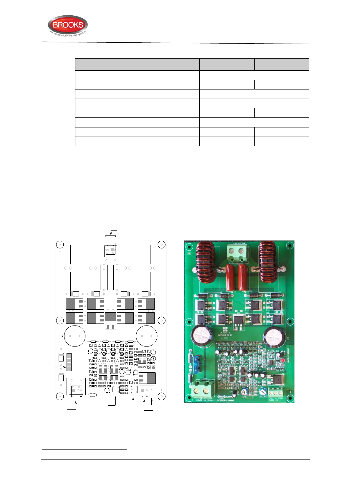
Table 7 OWS 60/120W amplifier specifications
Function
60W version
120W version
Voltage input range
20 to 32Vdc
Fuse rating
5 A (blade fuse)
7.5 A (blade fuse)
Low voltage shutdown
15 V (approx)
Audio input impedance
10 kΩ
Output load
4 Ω
2 Ω
Amplifier quiescent Current
38
40 mA
Total OWS quiescent Current
38
118 mA
119 mA
Total OWS active current – full load 38
2.8 A
5.17 A
AUDIO OUT
O VER- CURRENT
AUDI O I N
CAL.
ST DB Y
VO LUM E
PO W ER I N ( 24 Vdc )
C1 5
Z3
Z2
U5
R2 9
R2 8
R2 7
R2 6R2 5
R2 4
R2 3
R2 2
R2 1 R2 0
R1 9
Q 2 6
Q 2 5
Q 2 4Q 2 3
L ED1
D1 9D1 8
C2 6
C1 6
C1 4
D1 2
R1 6
C1 3
R1 0
R8
R3
Q 2 0
Z1
VR 2 V R1
U6
U4
U3U2
U1
R6 0
R5 9
R5 8R5 7
R5 6
R5 5
R5 4
R5 3
R5 1
R4 9 R 48R4 5
R4 3
R4 2R 41
R4 0
R3 8 R 37
R3 4
R3 3
R3 2
R3 1
R1 5
R1 3
R9
R7 R6R5R4
R2
R1
Q 1 9
Q 1 8
Q 1 7
Q 1 6
Q 1 5
Q 1 4 Q 1 3Q 1 2Q 1 1
Q9Q8 Q7Q6
Q4 Q3Q2Q1
L2
L1
F1
D5 D4D3 D2
D1
CO N3
CO N 2
CO N 1
C3 4
C3 3
C3 1
C3 0
C2 9
C2 5
C2 4 C 23
C2 2
C2 1
C2 0 C1 2
C1 1
C1 0
C9C8C6
C5
C4
C3
C2
C1
C3 5
C3 6
C3 7
R1 2
D6 D7D8 D9
D1 0 D1 1D1 3
D1 4
BRO O K SAUS TRAL I A
C7
D1 5D1 6 D1 7
Q5 Q 1 0Q 2 1 Q 2 2
R1 1 R1 4R1 7 R1 8
SUB867PCB219R2
TO SPEA K ER /
100 V A U D IO TR A N SFO R M ER
VO LU M E A D JU C TM EN T
A U D IO IN PU T
PO WER IN PU T
STA N D B Y
C A LIB ER A TIO N
( FACTORY USE O NLY)
FU SE
(15A )
38
5.4.2.2 250 Watt Amplifier Module
High energy efficiency class D amplifier design.
Low voltage protection.
Technical / Programming Manual
FT128 Rev 2.2
Over current protection
Standby function to reduce power consumption.
Current measured at 27V supply
Figure 19 Class-D 250W Audio Amplifier Board Layout
43
Page 44
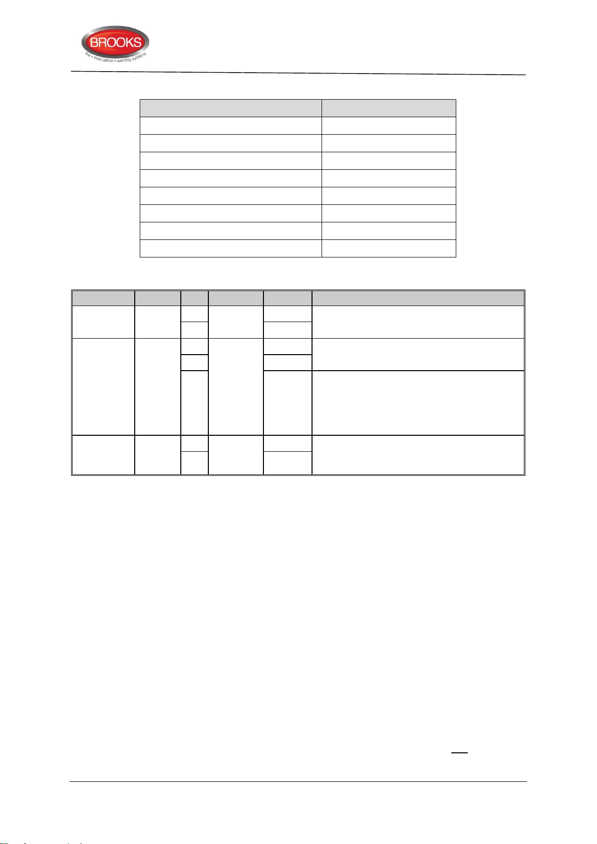
Technical / Programming Manual
Function
Rating
Voltage input range
20 – 32 VDC
Fuse rating
15 A (automotive blade fuse)
Low voltage shutdown
19 V (approx.)
Audio input impedance
10 kΩ
Output load
1 Ω
Amplifier Quiescent Current 38
40 mA
Total OWS quiescent current 38
119 mA
Total OWS active current – full load 38
10 A
Designator
Type
No.
Label
Pin
Description
CON1
Screw
terminal
1
24Vdc
+
Power input. 19V - 32V, 2.8A (60W), 5.2A
(120W), 10A (250W) 38
2
-
CON2
Screw
terminal
1
AUDIO
IN
+
Audio input <=1 V
RMS
. Input impedance:
10KΩ.
2
-
3
STDBY
Audio amplifier enable/disable input, logic
5V, <= 5mA. It is to minimize the unit power
consumption.
The amplifier output will be disabled when
the input is high.
CON3
Screw
terminal
1
AUDIO
OUTPUT
+
Audio output to the transformer secondary
side on the main control board. 16V
RMS
to the
associated different transformer.
2
-
Table 8 OWS 250W amplifier specifications
Table 9 Connection of the Audio Amplifier 60W, 120W and 250W
FT128 Rev 2.2
5.4.3 OWS Volume Adjustment
All volume adjustments are made on the Audio Amplifier Module via the trimpot VR1 only.
This volume adjustment is given a reference designator, VR1 and named “VOLUME” on all
amplifier boards. This trimpot, VR1, is shown in both Figure 17 page 42 and Figure 19 page
43. Do not use VR2 for adjusting the volume at any time, VR2 is only used for factory
calibration purposes.
The following procedures describe how to adjust the volume.
1. Manually turn on the evacuation tone.
2. Adjust the trimpot clockwise a little at a time to increase the volume on the audio
amplifier.
3. Then test or measure if the required audio level is met.
4. Repeat 1 to 3 as necessary.
5.4.4 Auxiliary Audio inputs
The OWS provides an auxiliary audio input controlled by a supervised auxiliary enable
input. The auxiliary audio input can be connected to a background music source and
enabled via the auxiliary input. The auxiliary inputs are also used to connect the Brooks
remote desktop microphones. When the CIE is in quiescent conditions and the auxiliary
enable input is activated, the auxiliary audio is activated and remote PA announcement or
background music will be broadcasted across the speakers.
44
Page 45
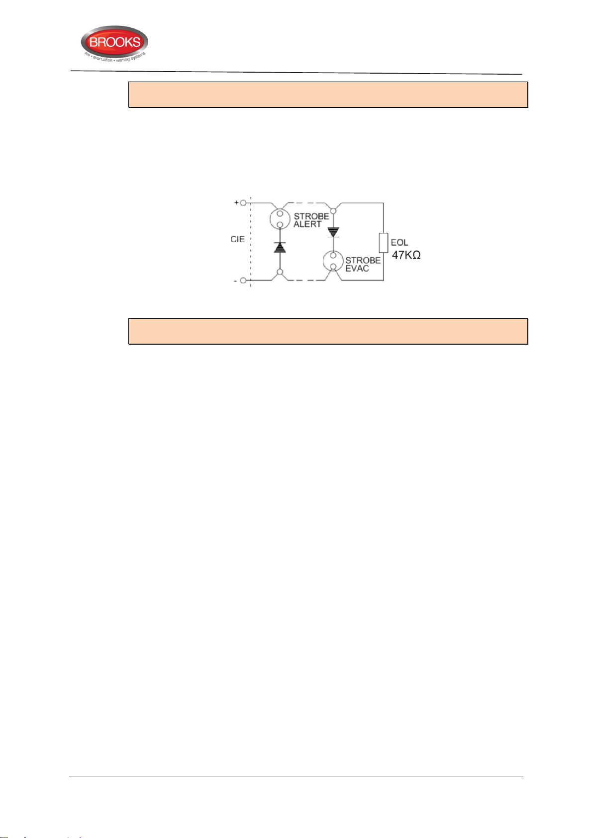
Note: Shielded cables must be used for Audio signals and its shielding should be
connected to the CIE EARTH terminal, this is to reduce disturbances.
5.4.5 OWS Dual Strobe Output
The OWS Dual Strobe output circuit is shown in Figure 20. A small current flows through
one of the two strobes constantly, which is normally too small to activate the strobes in
normal conditions. The EOL resistor of the output is 47KΩ, however, the EOL resistance
may vary based on the strobe model connected.
Figure 20 Typical OWS Dual Strobe Control Circuit
Note: Multiple dual strobes can be connected to the dual strobe output on the OWS main
board.
Technical / Programming Manual
FT128 Rev 2.2
45
Page 46

Technical / Programming Manual
5.5 Gaseous extinguishing system control module
5.5.1 Overview
The gaseous extinguishing system control module is provided for use as an option in
FT128. The module comprises the following:
Control Board (SUB928) with software for CIE interface.
Display Board (SUB929)
CIE interface board (SUB943).
Front panel decal with interconnection cable
The gaseous extinguishing system provides outputs to the following Brooks gas ancillary
equipment:
A series of Brooks Warning Signs
Brooks Local Control Station (LCS)
Voice / Tone Electronic Sounder
Dual Strobe Module
FT128 Rev 2.2
The control module combined with other Brooks system components is designed to provide
the monitoring and control functions of a complete gaseous extinguishing system that
meets the requirements of the relevant clauses 7.1 to 7.6 of the Australian Standard
AS4214-2002 (including amendment 1). For more details, refer to FT2GAS Operation /
Technical manual MA400.
The control module provides the following inputs / outputs:
Fully supervised gas release 24VDC output rated @ 5A maximum.
Fully supervised input circuits e.g. gas lock-off valve input, manual release input
and gas discharged sensor input.
Fully supervised system warning sign 24VDC output rated @ 0.5A maximum.
Fully supervised 2 wire system 24VDC output for level 1 and level 2 alarm to Brooks
warning signs (alarm 1 [+/-] & alarm 2 [-/+]) rated @ 3A maximum.
Gas release clean-contact relay output rated @ 2A maximum.
Gas Fault clean-contact relay output rated @ 2A maximum.
Gas Isolate clean-contact relay output rated @ 2A maximum.
Four-wire interface for Local Control Station (LCS). Both the local gas isolate
control and the local gas release control are fully supervised for open and short
circuit faults.
Adjustable gas release timer, set via a built-in DIP switch.
Note: Additional power supply and PSU supervision board must be used to power the
gaseous extinguishing system. The current rating above is the maximum current capacity
of the outputs, a power supply and battery calculations of the additional PSU must be
performed to ensure that the power supply capacity is sufficient to run the system in full
alarm condition without exceeding the maximum current rating of the power supply.
5.5.2 Display board (SUB929) & decal
The front decal of the gaseous extinguishing system is shown in Figure 21 below. The
display board SUB929 is mounted on the inner door behind the front decal.
All LED indicators on the front display are covered by a polycarbonate decal clearly labelled
with their functions.
46
Page 47
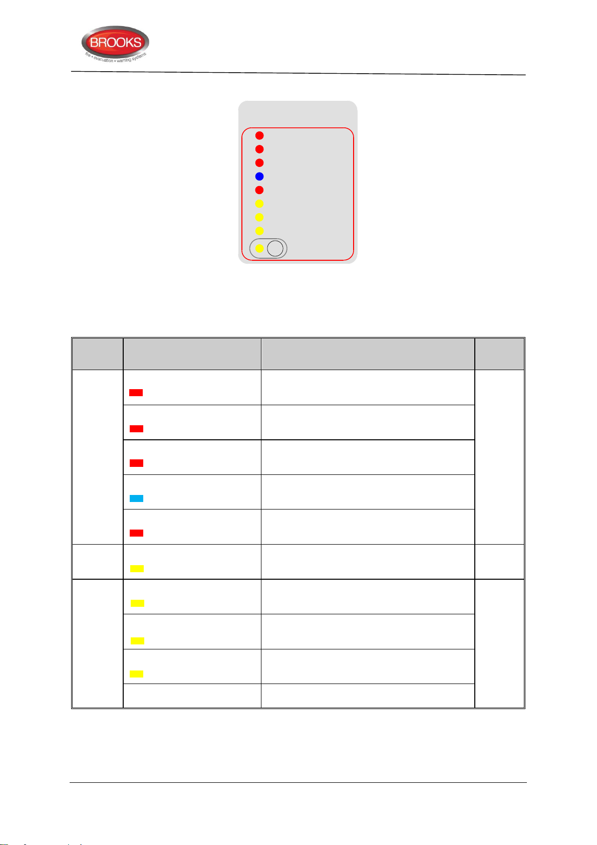
Technical / Programming Manual
Gas Extinguishing
2nd Alarm -Timer Running
Gas Fault
Gas Discharged
Gas Initiated
Gas Disabled
1st Alarm
Gas Discharge Inhibited
Gas Externally Released
Service
Master Abort
Type
LED Name
Module Conditions
LED
Pattern
Alarm
1st Alarm
One zone or zone address in alarm
Fast
Flash
2nd Alarm – Timer Running
Both zones or zone addresses in alarm
Gas Initiated
Gas release output activated
Gas Externally Released
External gas release control activated
Gas Discharged
Gas discharged sensor input activated
Fault
Gas Fault
Fault in any of the supervised inputs or outputs
Steady
ON
Disable
Gas Discharge Inhibited
Gas discharge inhibited via LCS isolate switch
Steady
ON
Gas Discharge Disabled
Gas discharge disabled by the service master
abort switch or the gas lock-off valve controls
Service Switch Active
Illuminates when the master abort switch is
activated
Service, Master Abort
Gas service master abort switch
FT128 Rev 2.2
When the system sets in the normal condition, all LED indicators will be extinguished.
Figure 21 Gas Extinguishing Display Layout
The gaseous extinguishing system status indicating LEDs and flash patterns are described
in Table 10 below. The default state of the LED indicators is OFF, if it is not defined below.
Table 10 Gas Front Status LED Indication and flash Pattern
5.5.3 Control board (SUB928)
The control board (SUB928) is mounted on top of the CIE interface board (SUB943) as
shown in Figure 22 below.
47
Page 48
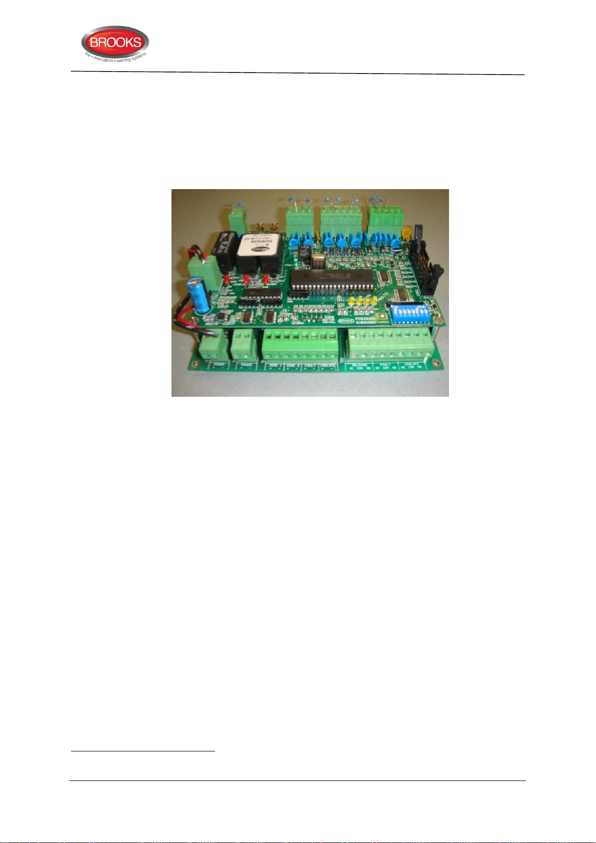
The gas control board SUB928 provides all the gaseous extinguishing control functions. It
39
40
provides the termination and supervision of all the field equipment.
5.5.4 CIE interface board (SUB943)
The CIE interface board (SUB943) is mounted at a suitable location inside FT128 cabinet.
It provides the required terminations to interface the gas control board SUB928 to FT128.
This includes zone alarm, Zone fault, zone isolate and gas release conditions.
Technical / Programming Manual
FT128 Rev 2.2
Figure 22 Assembled Control & Interface Boards
5.5.4.1 Inputs from FT128 to CIE interface board (SUB943)
The following inputs are provided in the gas interface board:
1. 24VDC supply (22-30V), 200mA to 3A based on system power calculation39
2. Zone 1 & Zone 2 alarm input from FT128, normally open clean alarm contact for
each zone or zone address required to activate the gas system.
3. Fault input40, zone 1 fault, zone 2 fault or power supply fault in the CIE will activate
the system inoperative sign. Fault input from FT128 should be normally closed
clean contact.
4. Zone Isolate input, if any of the two zone inputs or zone addresses used to release
the gas is disabled (open contact), the system inoperative sign will activate.
5.5.4.2 Outputs from CIE interface board (SUB943) to FT128
The following outputs from SUB943 are provided to indicate the gaseous extinguishing
system status in FT128 display via programmable inputs:
1. Gas isolate, relay output to indicate in FT128 if the gas has been isolated.
2. Gas fault relay output to indicate in FT128 if a fault exists in the gaseous
extinguishing system.
3. Gas release relay output to indicate in FT128 if the gas has been released.
Separate power supply must be used for the gas system,
Individual zone fault output can be configured only in software => V2.0.x software.
48
Page 49
6 Peripheral Devices
41
42
43
44
Alarm points, analogue alarm points (detectors, MCP’s, etc.) are connected directly to a
COM loop. Conventional alarm points (detectors, MCP’s etc.) are connected to a Zone
Line Input in an 8 zones expansion board (4580) or a Zone Line Input in a COM loop unit
3361. Programmable inputs can also be used for flow switches etc.
Short Circuit Isolators must be used on the COM loop if more than 40 alarm points are
connected to the COM loop.
I/O Matrix boards are plugged ("piggy back") to an Application board (Zone, Fan, Generic,
etc.), which is connected to the COM loop, refer to chapter “Expansion Boards 458X”, page
22.
Sounders, Strobes, door holders, etc. are connected to the programmable outputs in FT128
(S0-S1, R041) and/or to COM loop output units e.g. 3364 / 3361 and/or 8 relays expansion
boards 4581. Addressable sounders (3379 / 4477) are connected directly to the COM loop.
Input devices e.g. timer, external fault, etc. are connected to programmable inputs, i.e. to
input (I0) in FT128 and/or to input units connected to the COM loop e.g. 3361.
Routing equipment (Fire brigade TX / Fault TX) is normally connected to the R0-R1 outputs
in FT128. Also any programmable output can be used.
Technical / Programming Manual
FT128 Rev 2.2
Remote display units 42 are connected to the RS485 interface43 in FT128.
For more information, see the following Sections and the Product Leaflets on our web site:
http://www.brooks.com.au
6.1 COM Loop Units
The COM loop supports up to 255 addressable COM loop units 44 for software version ≥
V2.0.x.
Note: Depending on the type and number of units, the total current consumption will vary.
The cable length is dependent on the current consumption and the cable resistance.
See chapter "Current Consumption”, page 168.
The following units can be connected to the COM loop in NORMAL mode (some units can
be used in different modes):
R0 is normally used to trigger the OWS (if fitted). FT128 termination board also has a relay activated from S1, it can be used
to trigger the OWS or to control magnetic door holders (up to 2 A).
External Presentation unit 1728 and Alert Annunciation unit 1736
An optional RS485 transceiver component 4552 is required.
Conventional detectors can be connected to an 8 zones expansion board 4580 or to the Zone Line Input (Z) on an addressable
I/O unit 3361.
49
Page 50

Technical / Programming Manual
FT128 Rev 2.2
Notes:
The following loop units are not available in Australia or New Zealand:
• Customized units: Customised I/O 1 (1=Exit Light),
• Multi Detector with CO: 4402
• Wireless Units: 4611, 4620
• Aspiration Detectors: AE2010 L-P Aspect Lazeer, & AE2010N/G-P Aspect Nitro/Grizzle
Notes: 3361 The I/O Unit for Fan control is used only in the Fan control applications.
AAFC the Alarm Acknowledge Facility Control is used in conjunction with AAM
Obsolete loop units (listed below) may be found in old installations and can be used in
FT128 installations as well.
50
Page 51
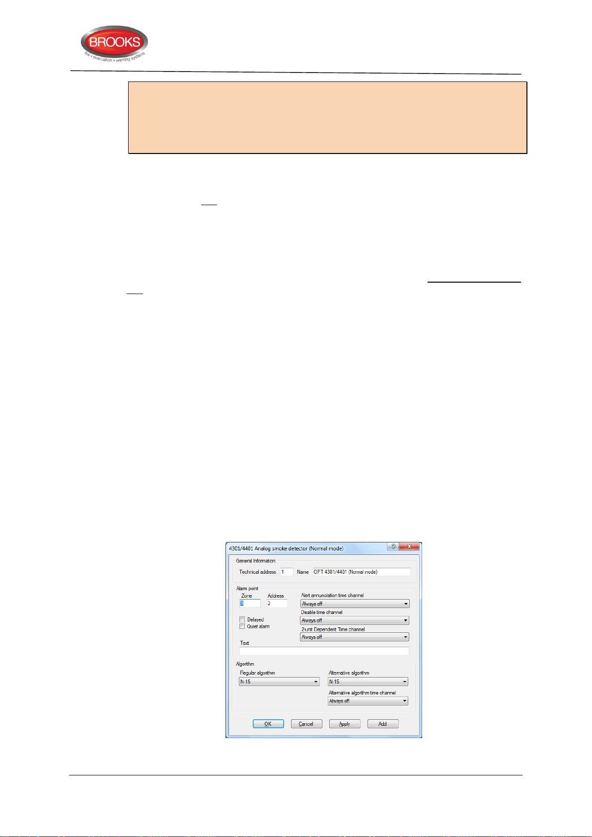
Notes:
3333/3339 can be used instead of 4433/4439 when the built-in Short Circuit Isolator is
not to be used.
3377 can also be used instead of 4477 when the built-in Short Circuit Isolator is not to be
used
Address setting / Technical address
Each COM loop unit must have a unique technical address (001-255). This address and
the mode are set with an Address Setting Tool 3314 / 4414. Except otherwise stated, the
NORMAL mode is used in FT128 (default). To set the detectors 440x in Advanced Mode,
the Address Setting Tool 4414 must be used.
6.1.1 Input Units
Each COM loop input unit is added and programmed via EBLWin. Depending on type of
unit, the following to be programmed:
Technical address (COM loop address) 001-255
Name (normally not changed)
Technical / Programming Manual
FT128 Rev 2.2
Zone number and Address within the zone
Alarm text (user definable)
Regular Alarm algorithm (some units only)
Options
Alternative Alarm algorithm & Time Channel (some units only)
Alert annunciation & Time Channel (some units only)
Disablement & Time Channel (some units only)
Two-units-dependent fire alarm, i.e. co-incidence alarm & Time Channel (some
units only)
Delayed (fire alarm)
Quiet alarm
Figure 23 EBLWin Properties Dialog Box for 4301/4401 (Normal Mode)
51
Page 52
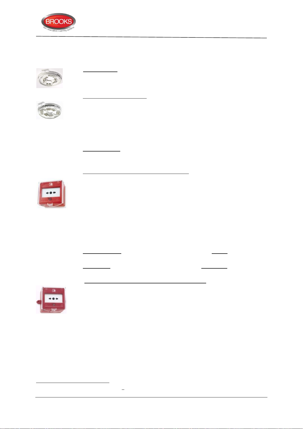
6.1.1.1 Analogue Sensor Bases (ASB)
45
46
An Analogue detector (Sensor) to be plugged in an Analogue base. The COM loop address
is set in the detector, see below.
3312 Analogue Base 3312 has screw terminals for the COM loop and an RIL. Prepared
for mechanical lock of the detector - if required. Recess for label holder (3391).
The base has an address label on which the plugged-in detector's COM loop
address can be written.
4313 Analogue Base with isolator. An Analogue detector (Sensor) is to be plugged in
4313. Terminals are provided for remote indicators (RIL). Prepared for mechanical
lock of the detector - if required. Recess for label holder (3391). It has also a builtin Short Circuit Isolator (see page 62). The isolator's COM loop address is set with
the Address setting tool 3314 / 4414. The base has an address label on which both
the plugged-in detector's COM loop address and the isolator's COM loop address
can be written.
The Address setting tool 3314 / 4414 is also used for mode setting:
NORMAL mode: Used for 4313 in system FT128.
6.1.1.2 Addressable Manual Call Points
Technical / Programming Manual
FT128 Rev 2.2
4433 Addressable Manual Call Point45 with isolator. Conforms to EN54-11, replaces
3333. This MCP is similar to 3333 but it also has a built-in Short Circuit Isolator. A
built-in LED will indicate that a fire alarm is generated, i.e. the glass is broken.
Routine testing can be performed with a supplied test key, without breaking the
glass. A hinged polycarbonate flap protects the glass from accidental triggering.
The COM loop address is set with the Address setting tool 3314 / 4414.
The isolator does not use any COM loop address
4433 is to be surface mounted in the supplied red back box or flush mounted as it
is mounted in the FT128 cabinet.
For indoor use and in dry premises.
The Address setting tool 3314 / 4414 are also used for mode setting:
NORMAL mode: The built-in Short Circuit Isolator is in use. Programmed in
EBLWin as MCP type 4433. Flashing or non-flashing LED is set via EBLWin.
2330 mode: The built-in Short Circuit Isolator is not in use. Programmed in
EBLWin as MCP type 3333. 46 Flashing or non-flashing LED is set via EBLWin.
4439 Enclosed Addressable Manual Call Point with isolator45. Replaces 3339. 4439 is
same as 3339 unit but it has built-in Short Circuit Isolator. The isolator does not
use any COM loop address. The Address setting tool 3314 / 4414 is also used for
mode setting same as 4433.
For indoor use in premises where IP56 rating is required. Operating temp. -10 to
+55°C.
Addressing & programming 4433/4439 with SCI
1. Connect the address setting tool to the MCP terminals SA and SB (without loop
connection).
2. Turn on the address setting tool then hold down both Write and Read buttons
simultaneously until “MODE: 0-3” appears.
3. Press “0” to select “M0 NORMAL” mode.
4. Enter the required technical address then press “write”.
The manual call points have a response time < 5 s
When 4433/4439 is used as a replacement for 3333/3339, in EBLWin, 3333/3339 must be selected (not 4433 or 4439).
52
Page 53
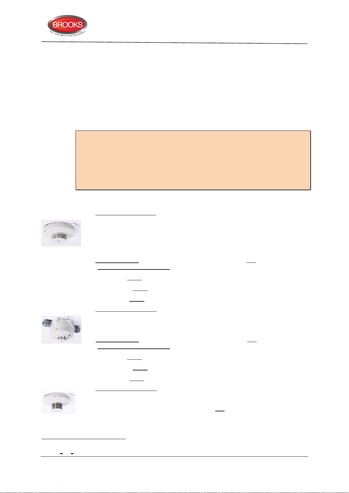
Technical / Programming Manual
47
FT128 Rev 2.2
In EBLWin, select 4433/4439 from add loop unit and add to the COM Loop.
Addressing & programming 4433/4439 without SCI
1. Connect the address setting tool to the MCP terminals SA and SB (without loop
connection).
2. Turn on the address setting tool then hold down both Write and Read buttons
simultaneously until “MODE: 0-3” appears.
3. Press “1” to select “M1 2330” mode.
4. Enter the desired technical address then press “write”.
In EBLWin, select 3333/3339 from the “Obsoleted units” and add to the COM Loop.
Notes:
1. Incorrect addressing mode or programming will cause the unit to report a “No reply
…..” fault in the control unit.
2. When 4433 or 4439 is used in FT512 system, the MCP must be addressed in 2330
mode and programmed as 3333 / 3339.
3. The Short Circuit Isolator feature in 4433 or 4439 can be used only in FT1020G3 or
FT128
6.1.1.3 Analogue Detectors
3308 Analogue heat detector. To be plugged in an Analogue base (3312 / 4313 / 3379).
Built-in LED is lit to indicate that the detector has activated a fire alarm. Prepared
for mechanical lock (screw attached) – if required. The COM loop address is set
with the Address setting tool 3314 / 4414. The detector has an address label on
which the programmed COM loop address can be written.
The Address setting tool is also used for mode setting:
NORMAL mode: 3308 is set in EBLWin in this mode to one of three algorithms
(static response temp. range) for class:
A1 (54-65°C), min./typical/maximum ambient temp. -20/+25/+50°C
A2 S (54-70°C), min./typical/maximum ambient temp. -20/+25/+50°C
B S (69-85°C), min./typical/maximum ambient temp. -20/+40/+65°C
3309 Analogue heat detector. Enclosed (IP67)47. Built-in LED is lit to indicate that the
detector has generated fire alarm. Terminals for Remote Indicator (RIL). Recess
for label holder (3391). The COM loop address is set with the Address setting tool
3314 / 4414. The Address setting tool is also used for mode setting:
NORMAL mode: 3309 is in this mode via EBLWin set to one of three algorithms
(static response temp. range) for class:
A1 (54-65°C), min./typical/maximum ambient temp. -20/+25/+50°C
A2 S (54-70°C), min./typical/maximum ambient temp. -20/+25/+50°C
B S (69-85°C), min./typical/maximum ambient temp. -20/+40/+65°C
4300 Analogue multi detector. Discontinued and replaced by 4400 in Normal mode, see
below. 4300 is a smoke detector and a heat detector within the same housing.
Scattered light (i.e. reflection of infrared light) is used to detect smoke and the heat
sensing element is a thermistor. The detector unit (actually the heat detector) can
detect methylated spirits (alcohol) fire (EN54-9, test fire TF6; liquid fire), which is
normally impossible for a photo electric smoke detector to detect.
As from July 2013, this detector holds the ATEX classification: Ex II 3 G Ex ic IIC T5 Gc, Ex II 3 D Ex ic IIIC T70°C Dc,
-20°C < Ta < 65°C.
53
Page 54
Technical / Programming Manual
50
48
49
50
Zone- Address
001-01(smoke or
heat)
Technical address
000123
20°C => 3.8 %/m
↓ ↓
40°C => 1.8 %/m
Zone-Address
001-01 (smoke)
001-02 (heat)
COM loop
address
e.g. 123
FT128 Rev 2.2
The detector has unleaded soldering.
To be plugged in an Analogue base (3312 / 4313 / 3379).
Built-in LEDs are lit to indicate that the detector48 has activated a fire alarm.
Prepared for mechanical lock (screw attached) – if required.
Via EBLWin, the mode of operation can be selected as follow:
a) Two presentation numbers (address): The detector unit works as two
separate detectors. The smoke detector is programmed for one zone-address
and the heat detector for another zone-address49. (Can be used to disable
e.g. the smoke detector during working hours and/or in control expressions for
programmable outputs).
b) One presentation number (address): The detector unit works as one
detector and is programmed for one zone-address.
If alternative b) is to work with "OR-functionality" or with a "Decision algorithm",
program this via EBLWin using either of these functionality options:
b1) OR-functionality: Either the heat detector or the smoke detector
will activate fire alarm. This alternative is recommended in most cases.
b2) Decision algorithm:
Fire alarm will be activated if:
Temperature (°C) + adjusted smoke value
> 58.
Pre-warning will be activated if:
58 > temperature (°C) + adjusted smoke value50 > 50.
The "Decision algorithm", see Figure 24, can be used to reduce false
alarms (nuisance alarms), because at a normal room temperature, more
smoke is required to activate fire alarm than when the room temperature
is high (or is rising). In a real fire condition, the room temperature will rise
rather fast and less smoke is required to activate fire alarm. Very little
smoke requires a "high" temperature to activate fire alarm and a lot of
smoke will activate fire alarm also at a "low" temperature.
i.e. the heat detector and/or the smoke detector.
The zone number has to be the same for both detectors. NOTE! When counting alarm points these "two detectors" are
Adjusted smoke value = obscuration (%/m) x 10. Default heat alarm levels (50°C / 58°C) and smoke alarm offsets (50 / 58)
regarded as two alarm points.
can be changed via EBLWin. The temp. Cannot be lower than 0°C in the algorithm / graph.
54
Page 55
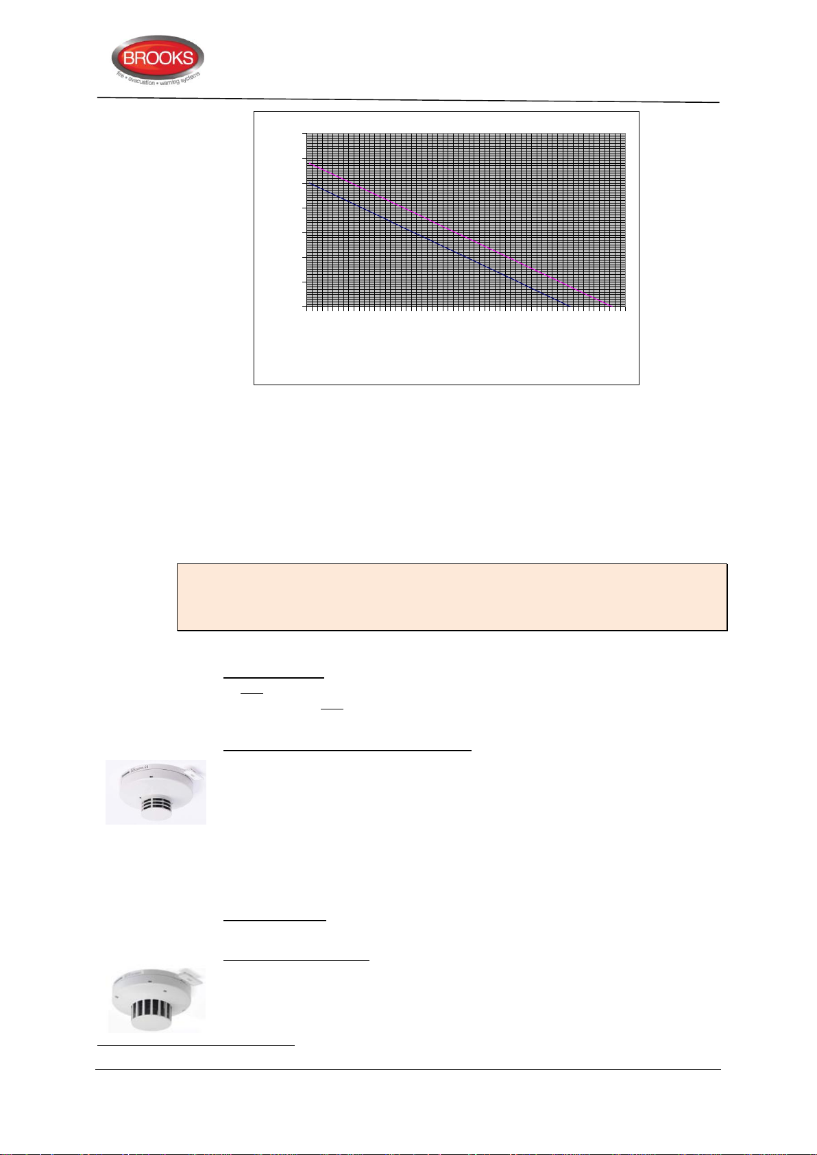
Technical / Programming Manual
51
0
10
20
30
40
50
60
70
0 4 8 12 16 20 24 28 32 36 40 44 48 52 56 60
Temperature
Smoke value
FT128 Rev 2.2
Figure 24 Decision Algorithm Graph.
When the calculated value in the decision algorithm exceeds the lower graph, prewarning will be activated. When it exceeds the upper graph, fire alarm will be
activated.
Temperature = °C. Smoke value = obscuration (%/m) x 10.
The technical address is set with an Address setting tool 3314 / 4414. The detector
has an address label on which the programmed technical address is to be written.
Note: The multi detector 4300 in system FT128 takes two COM loop (technical)
addresses of the available 255 addresses. One address that is set with the 3314 / 4414
tool but also the following address will be "occupied" for the heat part of the detector and
cannot be used by any other unit on the COM loop.
The Address setting tool 3314 / 4414 is also used for mode setting:
NORMAL mode: 4300 is set to this mode in EBLWin. For the smoke detector, set
to one of six algorithms H-15, H-35, L-15, L-35, N-15 or N-35 and for the heat
detector set to one of three algorithms for class A1 (static response temp. 5465°C), A2 S (54-70°C) or B S (69-85°C).
4301 Analogue photo electric smoke detector. Discontinued and replaced with 4401
in Normal mode, see below. Scattered light (i.e. reflection of infrared light)
is used to detect smoke. To be plugged in an Analogue base (3312 / 4313 /
3379). Built-in LEDs are lit to indicate that the detector has activated fire alarm.
Prepared for mechanical lock (screw attached) – if required.
The technical address is set with the Address setting tool 3314 / 4414. The detector
has an address label on which the programmed technical address can be written.
The Address setting tool 3314 / 4414 is also used for mode setting:
4400 Analogue multi detector. Replaces 4300 in Normal mode, see above. 4400 is a
I.e. the heat detector and/or the smoke detector.
NORMAL mode: 4301 in this mode is set in EBLWin to one of the six alarm
algorithms H-15, H-35, L-15, L-35, N-15 or N-35.
smoke detector and a heat detector in one housing. Scattered light (i.e. reflection
of infrared light) is used to detect smoke and the heat sensing element is a
thermistor. To be plugged in an Analogue base (3312 / 4313 / 3379). Built-in LEDs
are blinking to indicate that the detector 51 has activated fire alarm. Prepared for
55
Page 56

Technical / Programming Manual
52
FT128 Rev 2.2
mechanical lock (screw attached), if required. 4400 has slightly different design to
the 4300 detector and the smoke chamber net has even made with smaller holes,
this will keep insects and particles 52 larger than smoke particles out of the
chamber.
The COM loop address (Technical address) is set with the Address setting tool
3314 / 4414. The detector has an address label on which the programmed technical
address can be written.
The Address setting tool is also used for mode setting:
Advanced mode: Only the new Address setting tool 4414 can be used to set 4400
to “Advanced” mode. Note, the Address setting tool 3314 cannot be used to set
“Advanced” mode!
In Advanced mode, 4400 will use an algorithms in the detector for fire alarm
evaluation. It can be set to a Learning function or via EBLWin to one of five area
alarm algorithms (Normal, Clean, Smoke/Steam, Cooking/Welding or Heater area),
see Section Advanced Mode, page 127.
An alternative smoke and/or heat algorithm can be used via one or two time
channels. 4400 has a green polling LED. Via EBLWin, the green polling LED can
be set to blink when the detector is polled or never blink. Note, the LED will not be
blinking if the detector is in Test mode.
In “Advanced” mode, only one COM loop address will be occupied for the multi
detector.
NORMAL mode: 4400 in this mode has to be programmed in EBLWin as a 4300
detector, i.e. the 4400 detector will work as a replacement for the Analogue multi
detector 4300 and two COM loop addresses will be occupied, see 4300 above.
The smoke detector part has to be set to one of six alarm algorithms H-15, H-35,
L-15, L-35, N-15 or N-35 and the heat detector part has to be set to one of three
alarm algorithms for class A1 (static response temp. 54-65°C), A2 S (54-70°C) or
B S (69-85°C). An alternative smoke and/or heat algorithm can be used via one or
two time channels.
4401 Analogue photo electric smoke detector. Replaces 4301 in Normal mode, see
above. Scattered light (i.e. reflection of infrared light) is used to detect smoke. To
be plugged in an Analogue base (3312 / 4313 / 3379). Built-in LEDs are blinking
to indicate that the detector has activated fire alarm. Prepared for mechanical lock
(screw attached) if required.
4401 has slightly different design to the 4301 detector and the smoke chamber net
has even made smaller with holes that will keep insects and particles 52 larger than
smoke particles out of the chamber. The technical address is set with Address
setting tool 3314 / 4414. The detector has an address label on which the
programmed technical address can be written.
The Address setting tool is also used for mode setting:
Advanced mode: 4401 has to be set to Advanced mode via only the Address
setting tool 4414. Note, the Address setting tool 3314 cannot be used to set
Advanced mode! In Advanced mode, this detector will use algorithms in the
detector for fire alarm evaluation. It can be set to a Learning function or via EBLWin
to one of three area alarm algorithms (Normal, Clean or Smoke/Steam area), see
Section “Advanced Mode”, page 127.
For example dust, steam, etc.
56
Page 57
An alternative area alarm algorithm can be used via a time channel. 4401 has a
green polling LED. Via EBLWin, the green polling LED can be set to either blink
when the detector is polled or never blink. Note, the LED will not be blinking if the
detector is in Test mode.
NORMAL mode: In this mode 4401 has to be programmed in EBLWin as a 4301
detector, i.e. the 4401 detector will work as a replacement of the Analogue
photoelectric smoke detector 4301 (see 4301 above) and has to be set to one of
six alarm algorithms H-15, H-35, L-15, L-35, N-15 or N-35. An alternative alarm
algorithm can be used via a time channel.
6.1.1.4 Conventional Detector Bases (CDB)
2324 Base. A conventional detector is to be plugged in a conventional detector base
2324. Built-in LED is lit to indicate that the detector plugged in the base has
activated fire alarm. Terminals for remote indicator (RIL) are provided.
6.1.1.5 Conventional Detectors
4318 Combination heat detector. Rate-of-rise and fixed temperature, 59°C, heat
detector class A1R. Static response temperature range 54-65°C, ambient
temperature minimum/typical/maximum -10/+25/+50°C.
Technical / Programming Manual
FT128 Rev 2.2
To be plugged in a conventional detector base 2324.
4350 Multi detector. This detector is discontinued and will not be replaced. 4350 is a
smoke detector and a heat detector within one housing. Scattered light (i.e.
reflection of infrared light) is used to detect smoke and the heat sensing element
is a thermistor. In order to secure the fire detection and to reduce false alarms, an
AI function is used, i.e.
a. Combined heat and smoke sensing
b. Variable delay function
c. Adaptive learning function
4352 Photoelectric smoke detector. Discontinued and replaced with 4452. Scattered
light (i.e. reflection of infrared light) is used to detect smoke. An advanced alarm
algorithm is used to secure the smoke detection and to reduce false alarms, e.g. a
minimum of nine consecutive readings over the fire alarm level are required before
the detector goes into alarm. (One reading per sec.). To be plugged in a
conventional detector base 2324.
4452 Photoelectric smoke detector. Replaces 4352, see above. Similar to 4352 but 4452
has a little different design compared to 4352 detector (see 4401 above) and the
smoke chamber net has smaller holes. This will keep insects and particles52 larger
than smoke particles out of the chamber.
4375 Heat detector. Fixed temperature heat detector, 60°C, class A2S (static response
temp. range 54-70°C), latching, minimum/typical/maximum ambient temperature
-10/+25/+40°C. To be plugged in a conventional detector base 2324.
4376 Heat detector. Fixed temperature heat detector similar to 4375 but 80°C, class BS
(static response temp. range 69-85°C), latching, minimum/typical/maximum
ambient temperature -10/+40/+60°C. To be plugged in a conventional detector
base 2324.
57
Page 58
Technical / Programming Manual
53
54
55
FT128 Rev 2.2
6295 Heat detector: Enclosed (IP67)53. Fixed temperature heat detector, 57°C, class
A2S (static response temperature range 54-70°C), latching. Minimum /typical/
maximum ambient temperature -40/+25/+50°C. Built-in LED is lit to indicate that
the detector has activated a fire alarm. Terminals for a Remote Indicator (RIL) are
provided.
6296 Heat detector: Enclosed (IP67)53. Same as 6295 but 72°C, class BS (static
response temperature range 69-85°C), latching. Minimum/typical/maximum
ambient temperature -40/+40/+65°C. Built-in LED is lit to indicate that the detector
has activated a fire alarm. Terminals for a Remote Indicator (RIL) are provided.
6297 Heat detector: Enclosed (IP67)
response temperature range 84-100°C), latching. Minimum/typical/maximum
ambient temperature -40/+55/+80°C. Built-in LED is lit to indicate that the detector
has activated a fire alarm. Terminals for a remote indicator (RIL) are provided.
6298 Heat detector: Enclosed (IP67)
response temperature range 114-130°C), latching. Minimum/typical/maximum
ambient temperature -40/+85/+110°C. No built-in LED but terminals for a Remote
Indicator (RIL) are provided to indicate that the detector has activated a fire alarm.
6.1.1.6 Accessories
3314 Address setting tool. Discontinued, replaced by 4414, is used to write or read the
COM loop units' technical address (001-255). It is also used to write or read the
mode, NORMAL or 2330 (see the unit respectively). A connection cable (with
crocodile clips and tab terminals) is supplied with the unit and can be used when
required.
Slide the ON/OFF switch to the ON position and wait for a beep. Plug the detector's
SA & SB terminals onto the tool's SA & SB terminals or when required, use the
connection cable.54
How to read: Press "READ", wait for a beep and read the address and mode.
How to write: Press "WRITE" and "READ" simultaneously to select the mode
and/or write the address. Press "WRITE" and wait for a beep. ("READ" again as
a check.)
53
. Same as 6295 but 87°C, class CS (static
53
. Same as 6295 but 117°C, class ES (static
4414 Address setting tool. Replaces 3314. Is used to write or read the units' COM loop
address (Technical address 001-255). It is also used to write or read the mode
(Advanced55, NORMAL and 2330), see the COM loop unit respectively for mode
information.
A connection cable with crocodile clips and tab terminals is supplied with the tool
and can be used when required.
4414 replaces 3314 but 4414 is only required when the 4400 and 4401 detectors
are configured for the Advanced mode.
Turn on the tool (On/Off/CLR button). A blinking curser and mode M0 will be
shown in the display. Plug the detector's SA & SB terminals onto the tool's SA
& SB terminals or, when required, use the connection cable54.
How to read: Press "Read", wait for the OK, address and mode info and a beep.
How to write: To change the mode (if required) press "Write" and "Read"
simultaneously then press 0, 1, 2 or 3 for the mode respectively. Type the
address (1-255) and press "Write". Wait for OK, address and mode info and a
This detector holds the ATEX classification: Ex II 3GD EEx nA II T5 (T 100°C), -40°C < Ta < 50°C.
Some units have flying leads for easier connection. After use they might be disconnected and thrown away.
Address setting tool 4414 has to be used to set the detectors 4400 and 4401 in Advanced mode. (Address setting tool 3314
cannot be used for the Advanced mode).
58
Page 59
Technical / Programming Manual
56
57
58
59
60
FT128 Rev 2.2
beep. (Press "Read" again to double check), Instructions are on
tool.
3309 Label holder. To be mounted on the analogue base 3312 / 4313 / 337956. Intended
for a label with "zone-address", "technical address", etc. to be read also when the
detector is plugged in its base. 100 label holders per packet, excludes labels.
3391 Labels for 3390. Packet with self-adhesive white labels for label holder 3390. 10
x A4-sheets, 132 labels for laser printer usage. The print-out is done via EBLWin.
6.1.2 Addressable I/O units
3361 Addressable multipurpose I/O unit57. COM loop powered unit.
The unit has two programmable inputs:
Monitored input
….used as Zone Line Input (Z) (terminals 6 & 7): End-Of-Line capacitor 10uF 58
mounted in the last unit on the zone line. A short circuit on the input can generate
a fault or a fire alarm (set via EBLWin). This input is intended for conventional
detectors.59 Max. 1.5 mA, cable characteristic is max. 50 and max. 50nf.
….used as general input (In0) (terminals 5 & 7): An input for NC or NO contacts
(set via BLWin).
Isolated input (In1) (terminals 8 & 9): An optocoupler input (external 24 VDC / 8
mA is required). Normally low or high (set via EBLWin).
The unit has two programmable relay60 outputs:
the rear of the
Relay output (Re0): NC or NO contacts (set via EBLWin).
Relay output (Re1): NC or NO contacts (set via EBLWin).
Connections and examples, see drawings F733 and F735. The unit's dimensions:
90L x 70W x 32H mm. A plastic protection cover is attached. The cover's
dimensions: 129L x 73W x 45H mm.
The unit is intended to be surface mounted and for indoor use in dry premises.
When required, the unit can be mounted in a Waterproof box (IP66 / 67). The unit
has an LED to indicate communication to the unit or alarm condition. For more
information, see the Product Leaflet. The technical address is set with an Address
setting tool 3314/4414. The unit has an address label on which the programmed
technical address is to be written.
The Address setting tool is also used for mode setting:
NORMAL mode: Used for 3361 in FT128.
Also in the enclosed analogue heat detector 3309.
The same physical unit (3361) is also used in AS1668 Fan control applications and has a separate dialog box in EBLWin.
470nF is revised to 10uF.
It is via EBLWin possible to define this input function to be a manual call point ("Used as MCP"), i.e. it cannot be disabled via
a time channel, cannot included in two-unit dependence or cannot use the “AVF” function.
Relay contacts: maximum 2 A @ 30 VDC / 125 VAC.
59
Page 60
Technical / Programming Manual
61
62
63
FT128 Rev 2.2
3364 Addressable 2 voltage outputs unit. The unit is connected directly to the COM loop.
External 24 VDC supply is required (via a 3366AU unit or FT128).
The unit has two programmable and supervised voltage outputs (VO0-VO1),
intended for alarm devices (e.g. sirens, strobes, etc). An End-Of-Line capacitor
(470nF) is to be mounted in the last device alternativly a capacitor (470nF) in up
to five alarm devices (T-off).
The unit also has a special voltage output (VO2) intended for fire door closing only.
The trigger condition "Fire door closing" and the controlling detectors have to be
programmed. The "fire door closing function" is described on page 99 and besides
that function, the output VO2 will also not be powered for approx. 30 sec. after:
the "/Mains OK input" (terminal 8) goes high, see below.
the COM loop communication is interrupted i.e. 3364 has no connection /
communication with FT128.
The unit has two inputs, i.e. one for 24 VDC supply and one for "/Mains OK".
VO0: Normally low or high (set via EBLWin), 24 VDC, 1 A.61
VO1: Normally low or high (set via EBLWin), 24 VDC, 1 A.61
VO2: Normally high, 24 VDC, 1 A.61 (Fire door closing function.)
24 VDC: From an external power supply (unit 3366AU or FT128)
Mains OK: From an external power supply unit (3366AU). Normally low =
the main power source (230 VAC) in the External power supply unit is
okay62.
For connections and examples, see drawings F733 & F737. The unit's dimensions:
90L x 70W x 32H mm. A plastic protection cover is attached. The cover's
dimensions: 129L x 73W x 45H mm. The unit is intended to be surface mounted
and for indoor use in dry premises. When required, the unit can be mounted in a
Waterproof box (IP66 / 67).
The technical address is set with an Address setting tool 3314/4414 while the unit
is powered. The unit has an address label on which the programmed technical
address is to be written.
The Address setting tool 3314 / 4414 is also used for mode setting:
NORMAL mode: Used for 3364 in FT128.
6.1.3 Alarm Devices (Addressable Sounders)
4477 Addressable siren. Replaces 3377, the new 4477 is similar to 3377 unit but it has
a built-in Short Circuit Isolator, refer to section 6.1.5 Built-in Isolators page 63. The
isolator does not use any COM loop address.
The power to the siren is supplied via the COM loop, i.e. the number of sirens is
dependent on the type and number of other units connected to the COM loop.63
Three sound types (tones) and three priority levels are available.
Steady (continuous) 990 Hz
Intermittent (pulsed) 990 Hz, 0.5s / 0.5s (1 Hz)
Alternating (two-tone) 990 / 650 Hz, 0.25s / 0.25s (2 Hz)
Cont. 1 A, during 10 ms 1.4 A.
When the 24Vdc power to 3364 is supplied from FT128, this terminal must be connected to negative. To simulate “Mains Ok”
for 3364.
The number of 4477 + 3379 units must be < 50.
60
Page 61
Technical / Programming Manual
64
65
FT128 Rev 2.2
For each level, an output control expression and a sound type is programmed (via
EBLWin). For more technical data, see the product datasheet.
The COM loop address is set with the Address setting tool 3314 / 4414 which is
also used for mode setting
NORMAL mode: 4477 with the built-in isolator in use.
2330 mode: 4477 with the built-in isolator not in use. 4477 replaces a 3377 unit.
Note: See also Table 2 “Control Panel Limitation”, page 16.
3379 Addressable sounder base. 3379 consists of an analogue base 3312 mounted
together with a sounder. 3379 is mounted in the ceiling. An Analogue detector can
be plugged in the base, which has screw terminals for the COM loop and a Remote
Indicator (RIL). Prepared for mechanical lock of the detector - if required. Recess
for label holder (3391). 3379 is COM loop powered i.e. the number of sounder
bases is dependent on the type and number of other units connected to the COM
loop 63.
Three sound types (tones)64 and three priority levels are available.
Steady (continuous) 3650 Hz
Intermittent (pulsed) 3650 Hz, 0.5s / 0.5s (1 Hz)
Intermittent (pulsed) 3650 Hz, 0.167s / 0.167s (3 Hz)
For each level, an output control expression and a sound type is programmed (via
EBLWin). High sound output (approx. 4.5 dB higher) can be selected via EBLWin
(more current will be required). For more technical data, see the Product datasheet.
The COM loop address is set with the Address setting tool 3314 / 4414. The unit
has an address label on which the programmed COM loop address can be written.
(The detector has its own COM loop address set via the Address setting tool).
The Address setting tool is also used for mode setting:
NORMAL mode: 3379 used in FT128.
Note: See also Table 2 “Control Panel Limitation”, page 16.
4380 Addressable beacon 65. 4380 is a visual alarm device of type A for indoor use. All
electronics, the LEDs and the lens are mounted in a red ABS housing. The beacon
comes with a shallow base (IP21C). A deep base is an option which gives the
beacon a higher IP protection (IP33C). 4380 is powered via the COM loop, i.e. the
number of beacons is dependent on the type and number of other units connected
to the COM loop but 10 maximum.
The light output is 1 Cd and the flash rate is 1 Hz. For more technical data, see the
Product Leaflet. NOTE! This unit has been removed from our product range.
The technical address is set with the Address setting tool 3314 / 4414. The unit has
an address label on which the COM loop address can be written.
The Address setting tool is also used for mode setting:
NORMAL mode: 4380 used in system FT128.
High tone can be selected via EBLWin V2.1.x and higher, more current will be required.
The addressable beacon is discontinued and will be replaced by new VAD’s
61
Page 62

4383 Light indicator. 4383 is a light indicator used to complement the audible alarm
66
devices. It is of type A for indoor use. All electronics and the eight red LEDs
(visible 360°) are mounted in a transparent ABS housing. Flash rate is 1 Hz. 4383
is COM loop powered, i.e. the number of indicators is dependent on the type and
number of other units connected to the COM loop. The light indicator is plugged
in an analogue detector base 3312, 3379 or 4313 and an analogue detector is
plugged in the light indicator.
A control expression for activation has to be programmed, similar to a
programmable output or alarm device. It takes one COM loop address. For
more technical data, see the Product Datasheet.
The COM loop address is set with the Address setting tool 3314 / 4414. The unit
has a label for the COM loop address and another label for the detector's COM
loop address.
The Address setting tool is also used for mode setting:
NORMAL mode: 4383 used in system FT128.
6.1.4 Short Circuit Isolators (Addressable)
According to the Australian standard AS1670.1, at least one Short Circuit Isolator must
be used every 40 alarm points on the COM loop. Up to 64 isolators can be connected
to FT128 COM loop.
Technical / Programming Manual
FT128 Rev 2.2
Each COM loop Short Circuit Isolator is to be programmed (via EBLWin) for the
following:
Technical address66
Name (Normally not changed)
Sequence Number (Serial Number in the COM loop’s A-direction) 0-63
For connections, see drawing F733.
4313 Analogue base with isolator. 4313 is an Analogue base with built-in Short Circuit
Isolator. In case of short circuit on the COM loop, the number of disabled units will
be minimised. 4313 is a COM loop powered unit. For more information, see the
Product Datasheet. The COM loop address is set with the Address setting tool
3314 /4414. The unit has an address label on which the programmed COM loop
address is to be written.
The Address setting tool is also used for mode setting:
NORMAL mode: Used for 4313 in system FT128.
Up to 64 Short Circuit Isolators can be used, which give 65 loop segments. Each isolator
has to be given a Sequence Number 00-63. The isolators have to be connected
consecutively (Sequence Number 00-01-02-03-04-05-06-07-08-09-10-11-12-13-14-15 …
up to 63) in the COM loop's A-direction.
Note: FT128 has one built-in isolator in the-A direction (no. "A") and one in the B-direction
(no. "B").
Short circuit / cut-off (break) on the COM loop
See Refer to Chapter 11 “Short Circuit Isolators” page 92 for more information. See also
FT128 Operation Manual, Section "Fault messages".
The units 4433, 4439 and 4477 have a built-in isolator that doesn't occupy any COM loop address and the isolator’s Sequence
Number is set in the dialog box for the 4433, 4439 and 4477 unit respectively.
62
Page 63
6.1.5 Built-in Isolators
The units 4433, 4439 and 4477 have a built-in isolators that do not require any separate
COM loop addresses, only the Sequence Number, 00-63. As an option, these units can be
used without the isolator in function. If so, they have to be programmed in EBLWin as if
they were 3333, 3339 and 3377 units and via the Address setting tool 4413 set to 2330
mode instead of NORMAL mode.
6.1.6 Units for Hazardous (Ex) Areas
In hazardous (Ex) areas, Intrinsically Safe (IS) and approved products are required. The IS
alarm points are connected to an interface outside the hazardous area.
Normally the analogue addressable units, IS smoke (2840) and heat (2841) detectors are
to be used. They are connected to an IS barrier unit (2842), which is connected to a CIE
via a COM loop.
Conventional units are connected via a Galvanic isolator MTL 5061 (2820) to an Expansion
board 4580 Ex Zone Line Input See drawings F735 and F736.
6.1.6.1 Galvanic isolators / IS barrier units
MTL5061 Galvanic Isolator (2820). The isolator is used to connect conventional
intrinsically safe detectors and manual call points to an expansion board 4580 Zone
Line Input (programmed in "Resistor-Ex" mode). The isolator has two Zone Line
Inputs and two outputs (Channel 1 & 2) and is mounted in a Waterproof box
(IP66/67), which has to be mounted outside the hazardous (Ex) area. Four
compression glands for the cable entries and two End-Of-Line resistors (10K) with
an area >230 mm2 are supplied. Box dimensions: 175L x 125W x 150H mm.
BASEEFA / ATEX classification: EEx ia IIC Tamb=60°C.
Technical / Programming Manual
FT128 Rev 2.2
2822 Isolated Zone Interface. The Isolated Zone Interface (2822) contains a waterproof
box (IP66/67) that is supplied with four compression glands for the cable entries,
an Isolated Zone Interface board (2823) mounted on a DIN rail, a DIN rail interface
intended for an I/O unit 3361 and one 8K2 EOL resistor. The box has to be
mounted outside the hazardous (Ex) area
A Galvanic isolator 2820 is to be connected to the Isolated zone interface 2822 (i.e.
to the Isolated zone interface board 2823), which is connected to a COM loop via
an Addressable multipurpose I/O unit 3361 that can be mounted inside the
waterproof box. (2820 and 3361 have to be ordered separately.) External power
supply 24 VDC (30 mA) is required. Box dimensions (L x W x H): 175 x 175 x 75
mm.
2842 Intrinsically safe (IS) barrier unit. The barrier unit is used to connect analogue
addressable IS detectors to a COM loop. The unit has connectors for COM loop
in / out, external power supply (24 VDC, 60 mA) and one IS COM line for connection
of up to 20 IS detectors 2840 and 2841. It is mounted in a Waterproof box
(IP66/67). Five compression glands for the cable entries are supplied. Box
dimensions (L x W x H): 280 x 280 x 133 mm. DEKRA: II (1) G [Ex ia Ga] IIC.
6.1.6.2 Intrinsically Safe Mounting Bases
YBN-R / 4 IS Intrinsically Safe mounting base (2812). In the base, an intrinsically safe
conventional smoke or heat detector can be plugged. The base has terminals for
the zone line (in/out) and for an RIL.
63
Page 64
Technical / Programming Manual
67
67
6.1.6.3 Intrinsically Safe Photoelectric Smoke Detectors
SLR-E-IS Intrinsically Safe photoelectric smoke detector (2810).
A conventional intrinsically safe photoelectric (optical) smoke detector, to be
plugged in the intrinsically safe mounting base (2812). The detector has two builtin LEDs that are lit to indicate that the detector has generated fire alarm. Zone
classification: Cat. 1, 2 or 3. BASEEFA / ATEX classification: EEx ia IIC T5, Tamb=
50°C. Max 20 per zone.
2840 Analogue IS smoke detector. An analogue / addressable photo- electric smoke
detector. The detector can be used with higher IP rating back- box. Three cable
glands are supplied with the back-box. The detector has one built-in LED to indicate
that the detector has generated a fire alarm. The detector is programmed in
EBLWin as an analogue photoelectric smoke detector 4401 (in NORMAL mode)
but it has to be connected to the COM loop via an IS barrier unit 2842. ATEX class:
Ex ia IIC T5.
6.1.6.4 Intrinsically Safe Heat Detectors
DCD-1E-IS Intrinsically Safe heat detector. A conventional intrinsically safe Rate of Rise
heat detector, fixed temperature 60°C (class A1), to be plugged in the intrinsically
safe mounting base. Two built-in LEDs that are lit to indicate that the detector has
generated fire alarm. Zone classification: Cat. 1, 2 or 3. BASEEFA / ATEX
classification: II 1 G EEx ia IIC T5, Ta= -20 to +55°C. Max 20 per zone.
FT128 Rev 2.2
2841 Analogue IS heat detector. An analogue / addressable heat detector. The detector
can be used with a back-box for higher IP rating. Three cable glands are supplied
with the back-box. The detector has one built-in LED to indicate that the detector
has generated fire alarm. The detector is programmed in EBLWin as an analogue
heat detector 3308 (in NORMAL mode) but it has to be connected to a COM loop
via an IS barrier unit 2842. ATEX class: Ex ia IIC T5.
6.1.7 Intrinsically Safe Manual Call Points
MCP 1A-R470SGIS Intrinsically Safe manual call point (2814). A conventional outdoor
manual call point (NO contact and alarm resistor 470Ω). The call point is connected
to Galvanic isolator 2820. The call point is surface mounted with the supplied backbox (IP67) and has two compression glands for the cable entries. BASEEFA /
ATEX classification: II 1 G EEx ia IIC T4, Ta = -30 to +70°C. Max 20 per zone.
6.1.8 Other COM Loop Units
3366AU External power supply. Conforms to AS7240.4. The unit is connected to a COM
loop, i.e. it is monitored from FT128 e.g. loss of the main power source will
generate a fault in FT128. It can be used as a power supply for external
equipment requiring 24 VDC with battery backup, e.g. the 3364 unit. It also has
a "/Mains OK" output (normally low), intended to be connected to the
corresponding input on the 3364 unit.
An oyster metal housing 320W x 330H x 125D mm is used for 3366AU. There
is space for two sealed Lead-Acid backup batteries, 2 x 12V, 7Ah or 12Ah as
the standby power source. Batteries with higher capacity (up to 60 Ah) have to
be placed outside the housing. There are cable inlets on the top, and back sides
of the housing.
The unit has one 24 V
up to 2.1 A or 0.85 A continuous current consumption, at the same time as the
power supply output for external equipment with
DC
The rated output voltage for the main power supply is 24 V ± 1%. Max. ripple 500 mVp-p. The rated output voltage for the
standby power source (the backup battery) is 18 – 28 VDC. NOTE! The voltage will, however, be decreased to approx. 15 V
while the output will be switched off in order to avoid damaging the batteries.
64
Page 65
Technical / Programming Manual
68
69
FT128 Rev 2.2
battery charging is in progress.68 In case of no battery charging e.g fire alarm,
the continuous current consumption can be up to 4 A.
It has a number of Battery Protection Functions, e.g. monitoring high current
output, low battery voltage etc. For more information, see the Technical
Description and the Product Datasheet.
The technical address is set with an Address setting tool 3314 / 4414. The unit
has an address label on which the programmed technical address can be
written.
The Address setting tool is also used for mode setting:
NORMAL mode: Used for 3366 in FT128.
AAM Brooks Alarm Acknowledgement Module69. The AAM is a box with an alarm
indication LED and a non-latching switch "Press to acknowledge & investigate
alarm".
One AAM per Alarm Acknowledgement Facility Control (AAFC) zone and up to 100
AAFC’s zones can be used. The COM loop address is set with the Address setting
tool 3314/4414. See also chapter "Alert Annunciation Applications" on page 112.
The address setting tool 3314/4414 is used for address and mode settings:
NORMAL mode: Used for AAFC in system FT128 version < V2.2.x
2330 mode: Used for AAFC in system FT128 version ≥ 2.2.x
Note: The new local alarm acknowledgement unit (LAAU) 4445 is developed by
Panasonic, it is equivalent to Brooks Alarm Acknowledgement Module (AAM).
4445 Local Alarm Acknowledgement Unit (LAAU). The LAAU consists of a PCB with an
alarm indication LED and green non-latching switch for acknowledgement of an
alarm. The PCB is mounted on the rear of a white ABS lid. It can be wall mounted
in a 65mm circular mounting box. One LAAU per LAA zone and up to 100 LAA
zones per control panel can be used. The COM loop address is set with the
address setting tool 3314/4414. See also chapter “Alarm Acknowledgement
Facility (AAF)” page 112.
The address setting tool 3314/4414 is used for address and mode settings:
NORMAL mode: Used for 4445 in system FT128 version ≥ V2.2.x
2330 mode: Used to program Brooks AAM.
Note: The programming in EBLWin and the operation of the Panasonic 4445 are typically
the same as for Brooks AAM but using different terminology i.e.
LAAU = AAM
LAA zone = AAFC zone
The mode setting is also different in software version ≥ V2.2.x
A current consumption of 0.85-2.2 A allows only the "low current charging mode", i.e. the battery capacity can be up to 27
Ah. A current consumption < 0.85 A allows the "high current charging mode", i.e. the battery capacity can be up to 60 Ah.
However, batteries larger than 12AH require different enclosure to suit.
The AAFC function in EBLWin V2.2.0 has been moved from “Add loop unit” menu tree to the “Obsolete loop unit” submenu.
65
Page 66
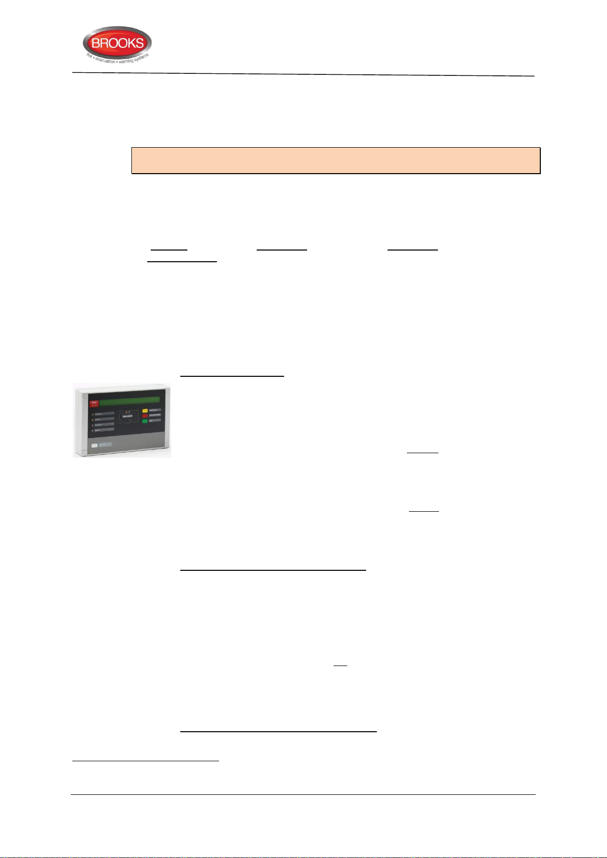
Technical / Programming Manual
70
71
6.2 Units Connected To Optional RS485 Interface
A combination of up to eight External Presentation Units (1728) or Alert Annunciation Units
(1736) can be connected to the RS485 interface 70 terminals on the termination board or
directly via (J1:15-16) in FT128. (Power supply at J1:13-14).
Note: RS485 interface module 4552 (chip) must be installed in the main board. Display
Unit software version => 1.4.1 is also required.
Address and S/W mode settings
The display and the push buttons (in the unit) are used to set the address, which also can
be changed via FT128. The S/W mode must be set to xxxx – 1587 (xxxx = type number).
Refer to the Technical Manual of 1728 and 1736.
The first unit is to have the address 00, the second unit address 01 and so on71. Follow
the Address setting instructions in the Technical Manual for each unit.
"Selective alarm presentation" can be programmed via EBLWin, i.e. you can select which
alarms to be presented in each unit, see the Technical Manual for the unit respectively.
6.2.1 Alert Annunciation Units
When the Alert Annunciation (AA) function is to be used in system FT128, a unit is required
for the related manoeuvres, i.e. to acknowledge / reset the AA alarms. For a detailed
description of the Alert Annunciation function, see Section "Alert Annunciation”, page 137.
FT128 Rev 2.2
1736 Alert Annunciation Unit (AAU). A compact size enclosure 145H x 220W x 50D
mm made of grey high impact ABS. Fitted with a supplementary "O" ring
gasket, it complies with IP61, in respect of dust and moisture. The unit has no
door, i.e. the front is accessed directly but the push buttons are disabled until
they are supposed to be used. The unit should be wall mounted. Two
compression glands are included.
All or selected fire alarms will be presented in a display (alphanumeric LCD,
2x40 characters), with back-light. An alarm text will also be presented together
with each alarm, if programmed in FT128. Furthermore, at least 617 texts can
be stored for selected fire alarms in the unit and will in such a case be shown,
instead of the texts sent out from FT128 for these alarms. These text messages
will be downloaded to the unit via FT128. A built-in buzzer will sound to indicate
a non-acknowledged AA alarm.
New software versions can be downloaded directly in the unit. The unit is power
supplied from FT128 or can be externalyl powered.
The unit has the following indications:
Fire and Alarms queued, indicating fire / AA alarm.
Operation, indicating that the unit is in operation, i.e. the AA function is enabled
in the system. A time channel can be used to enable the AA function.
Fire brigade alerted, indicating that the "Fire brigade TX" output is activated in
FT128 due to:
the activated fire alarm is not an AA alarm
the AA function has been terminated, e.g. the acknowledge or
investigation time respectively has run out, etc.
Acknowledge, indicating that the AA alarm has been acknowledged.
The unit has the following push buttons:
The RS485 transceiver 4552 is an option.
The connection order on the line is not dependent on the unit address.
66
Page 67
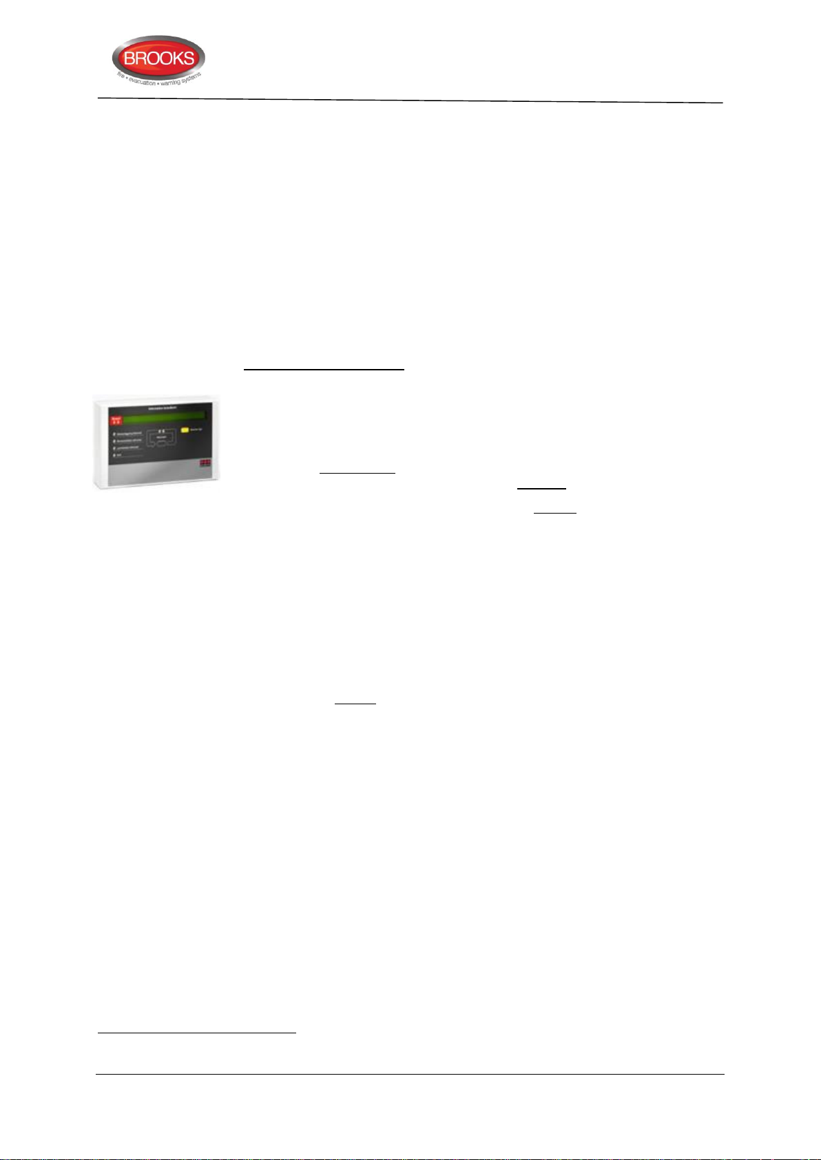
Alarms queued, used to scroll amongst the alarms.
72
73
Acknowledge, used to acknowledge an AA alarm and also silence the buzzer.
Silence alarm devices, used to silence OWS or sounders.
Reset, used to reset an AA alarm.
The unit must run in S/W mode 1736 – 1587, which has the highest
performance in regards to functionality, response time, ability to store alarms,
etc.
Up to 1200 m cable can be used for RS485, the 24V supply cable length is
mainly dependent on the cable size. Refer to Table 16 page 167. For more
information, see 1736 Technical Manual.
6.2.2 External Presentation Units
1728 External Presentation unit (EPU). Same enclosure as 1736 except that there
are 2 more buttons on the 1736 not exist in 1728, the Silence Alarm Devices
and Reset buttons also the Acknowledge button is renamed in 1728 to Silence
Buzzer. The push buttons are disabled until an alarm event is received. The unit
is to be wall mounted. Two compression glands are included.
This unit is intended for pre-warning, co-incidence72, fire (and heavy smoke /
heat) alarm presentation. If there are two or more alarms in the system, you
can scroll amongst them but the fire alarms cannot be reset via this unit.
Technical / Programming Manual
FT128 Rev 2.2
All or selected alarms will be presented in a display same as 1736 (alphanumeric LCD, 2x40 characters), with back-light. An alarm text will be presented
with each alarm, if programmed in FT128. Furthermore, at least 617 texts can
be stored in the unit for selected fire alarms and will in such a case be shown,
instead of the texts sent out from FT128 for these alarms. These text messages
will be downloaded to the unit via FT128.
Any fault in the system will be presented as "General fault in system", a built-in
buzzer will sound similar to FT128 buzzer and can be silenced. Any
disablement in the system will be presented as "General disablement in
system".
The buzzer can be silenced but the alarm devices in the system e.g. OWS,
sounders, etc. cannot be silenced via this unit. New software versions73 can be
downloaded directly in the unit. The unit is power supplied from FT128 or an
external power supply. The unit must run in S/W mode 1728 – 1587, which has
the highest performance in regards to functionality, response time, ability to
store fire alarms, etc.
The number of units that can be power supplied via FT128 (or an External
Power Supply) is dependent on all other units connected to the same CIE /
external power supply.
Up to 1200 m cable can be used for RS485. The 24VDC supply cable length is
mainly dependent on the cable size. Refer to Table 16 page 167. For more
information, see External Presentation Unit 1728 Technical description.
Two zone / address dependence.
Display units software => V1.4 must be used with FT128.
67
Page 68
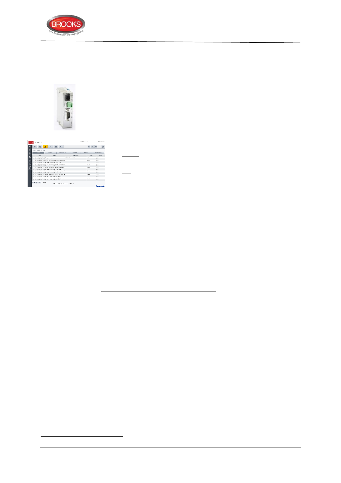
Technical / Programming Manual
74
6.3 Units Connected To RS232 Interface J5 (On 4556)
6.3.1 Web-servers
1598 Web-server II. This unit can be used in the following applications:
a) for presentation of the actual CIE status in a PC using a web browser such
as Microsoft Internet Explorer. It can also send e-mails in case of pre-warning,
fire alarm, fault, disablement, test mode alarm and/or service signal.
b) for remote control via two-way communication. Up to 10 User names with an
individual password74 and three different access levels.
c) as a gateway to other PC systems etc.:
c1) EBL Talk (RS232 or TCP/IP) is an open protocol, used to transmit and
present fire alarm information in a separate PC / system.
c2) Tateco, (RS232) used to transmit and present fire alarm information in
an Ascom Tateco paging system.
c3) SIA, (RS232) used to transmit and present fire alarm information in a
separate PC application.
c4) MODBUS (RS232) used to transmit and present fire alarm information
in a separate PC application.
FT128 Rev 2.2
d) As a gateway to a security management system via EBLnet. (TCP/IP)
EBLnet licence required.
The Web-Server has to be preconfigured with proper TCP/IP protocols using
@CHIPTOOL before setting up the Web-Server SSD configuration in the PC
program EBLWin. The Web-Server SSD configuration is downloaded to the
Web-Server via TCP/IP using an Ethernet cable. The Web-Server software is
also downloaded via the PC program EBLWin.
The Web-server II consists of a light grey plastic enclosure (90x25x69.5 mm),
which can be mounted on a 35 mm DIN rail inside the FT128 CIE.
Web-server II has the following interfaces:
RS232 (PLC COM) to connect the web-server to J5 in the FT128 CIE.
RS232 to connect the web-server to other PC / system
RJ45 (10 BASE-T) to connect the web-server to Internet / an intranet (LAN)
Molex 3.5 to connect the web-server to a power supply (24 VDC, maximum 65
mA), e.g. to J4 in the FT128 CIE.
Details for setting up the Web-Server is found in MA440 Web Server II Manual
Rev 1.0 for FT1020G3 and FT128.
6.4 Units Connected To RS232 Interface J3 (On 4556)
J3 is a 9 ways female "D" connector. This interface is used only for connection of the
FT128 to a PC with the PC program EBLWin, which is used for download / backup of Site
Specific Data (SSD), etc.
Consists of 6 digits.
68
Page 69
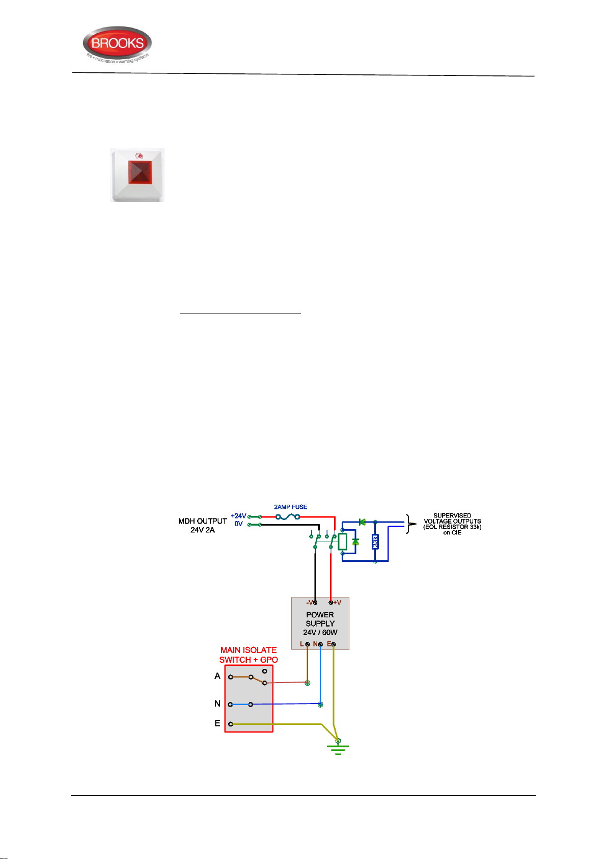
6.5 Other Units
6.5.1 External LEDs
BARIL Remote Indicator RIL. Used when a detector is placed out of view or hidden
e.g. roof space detectors. The LED is lit at the same time as the LED in the
detector / base that is connected to. It has a "Burning house" symbol instead
of a text. BARIL can be connected to all types of Panasonic detectors / bases.
To be wall mounted (87 x 87 x 30 mm).
The input is polarised, connections as follow:
J2:1 (+5 to +35 VDC) for Conventional detectors / bases
J2:2 (< 25 mA) for Analogue detectors / bases
J2:3 (0 V)
To be wall mounted (87 x 87 x 30 mm)
6.5.2 Alarm Devices (Sounders, Etc.)
Regarding addressable alarm devices, see page 60.
The alarm devices used in FT128 can be one or two of the following equipment:
Technical / Programming Manual
FT128 Rev 2.2
1. Occupant Warning System (OWS) with different power output built in FT128
and provides a supervised 100V speaker circuits and 24V dual strobe output.
2. 24VDC strobes or alarm bells connected to S0 – S1.
3. Full EWIS system interfaced to FT128.
Connections of alarm devices according to drawing F665 and F737.
6.5.3 Magnetic Door Holders
Different magnetic door holders to suit the applications are required. A separate 24V nonbattery backed power supply is recommended. Door holders must be provided with a
"suppression diode" (e.g. 1N4004) in parallel with the coil, similar to the alarm devices, see
drawing F665. Typical example is shown in Figure 25 below.
Figure 25 Connection example of 2A MDH power supply
69
Page 70

6.5.4 Duct Detector Chambers
6377 Duct Detector Chamber UG-4. The housing is made of grey ABS and the venturi
pipe is made of aluminium. It is supplied with four IP65 glands for cable entry.
6377 can be used in conventional as well as Analogue fire alarm systems,
depending on the base and detector mounted inside the housing (base 2324 +
4452 or base 3312 + 4401). The venturi pipe is available with or without a built-in
fan and in three lengths (0.6, 1.5 & 2.8 m). The pipe can easily be shortened to
suit the ventilation duct. Mounting bracket and filters are also available. For more
information see Duct Detector Chamber Datasheet.
Technical / Programming Manual
FT128 Rev 2.2
70
Page 71
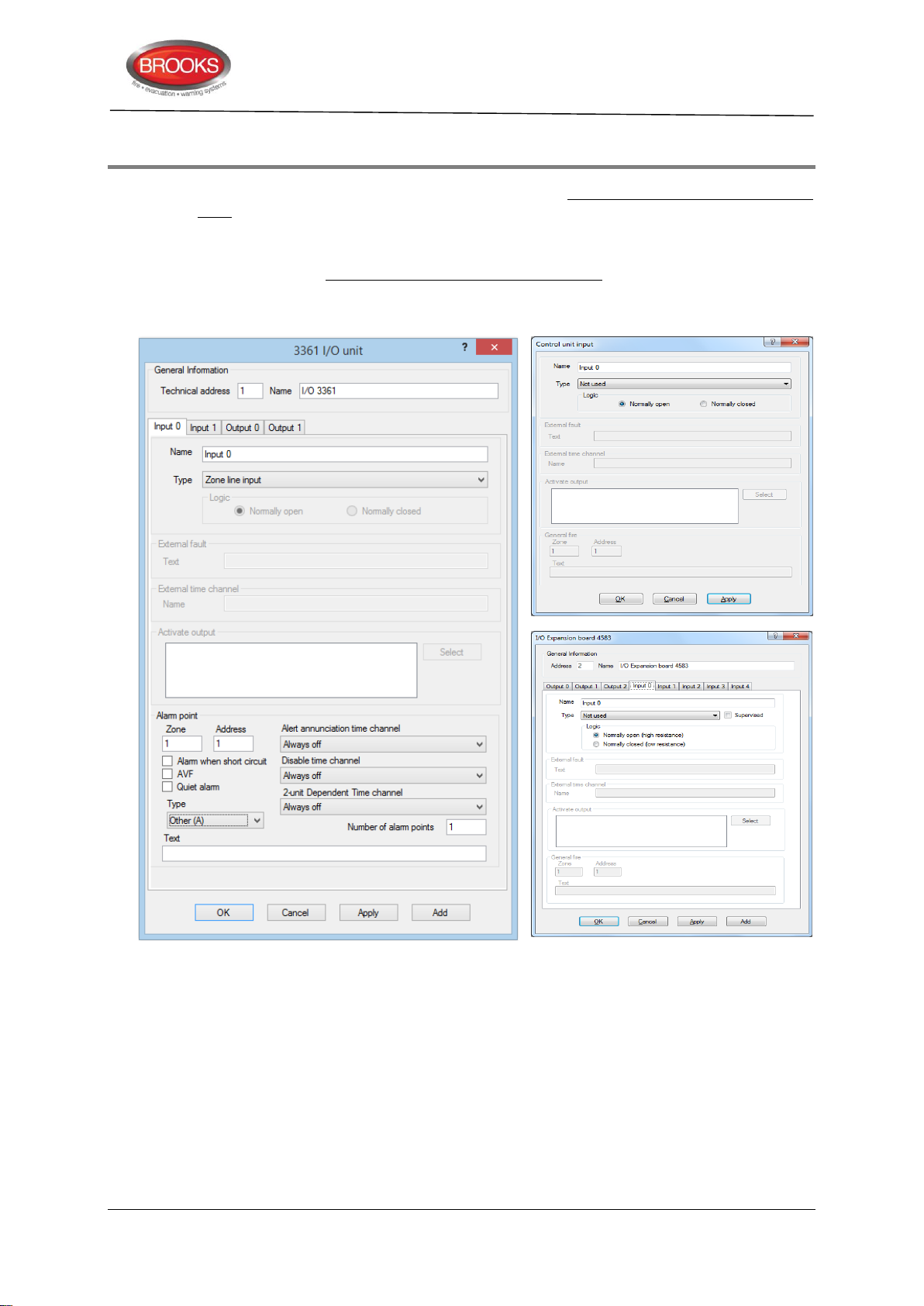
7 Programmable Inputs
FT128 has one programmable input (I0). In FT128, the Inputs and Outputs expansion board
4583 can also be mounted, five programmable inputs (Input 0-4) are available which can
be configured to be supervised or non-supervised. See chapter “Expansion Boards ” pages
22.
On the COM loop, addressable multipurpose I/O units 3361 can be connected. Each 3361
unit has two programmable inputs (In0/Z and In1), supervision is not configurable.
Each input is programmed via EBLWin as per the dialog boxes shown in Figure 26 below.
Technical / Programming Manual
FT128 Rev 2.2
Figure 26 EBLWin “Input” dialog Boxes
Different trigger conditions might require additional information i.e. only the enabled fields
can / should be filled in.
7.1 Control Unit Input I0
Connections, see drawing F665.
7.1.1 Not supervised
Normally open (R > 20KΩ) or Normally Closed (R < 500Ω)
Activation time: >1 sec.
71
Page 72
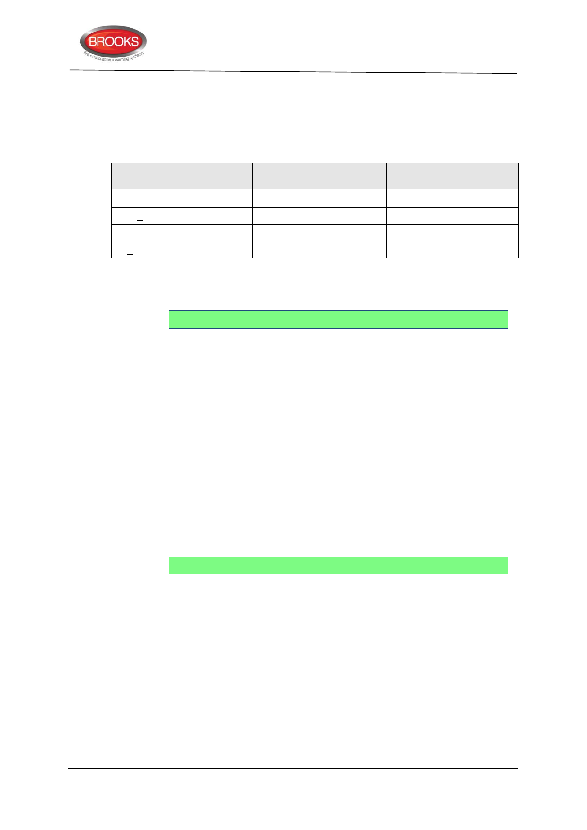
7.1.2 Supervised
Line resistance R
Normally Open
(high resistance)
Normally Closed
(low resistance)
R > 6K8
Fault, Open circuit (cut-off)
Fault, Open circuit (cut-off)
6K8 > R > 2KΩ (nom. 3K3Ω)
Not activated
Activated
2K > R > 70 (nom. 680)
Activated
Not activated
R < 70
Short-circuit
Short-circuit
Each supervised input can be in one of the four different states shown in Table 11 below
Depending on the selected logic, Normally Open (high resistance) or Normally Closed
(low resistance), the four conditions in the table are valid.
Table 11 Control Unit Inputs I0 & 4583 Inputs 0-4
Input line fault
If open circuit (cut-off) or short-circuit is detected on a supervised input, a fault will
be generated in FT128 and the following fault
FAULT: Programmable input
Technical / Programming Manual
FT128 Rev 2.2
message will be displayed:
7.2 Input 0-4 in Expansion Board 4583
Connections, see drawing F731.
7.2.1 Not supervised
Normally open (R > 20K) or Normally Closed (R < 500 ohm)
Activation time: > 10 sec.
7.2.1 Supervised
Each supervised input can be in one of the four different states shown in Table 11 above
Depending on the selected logic, Normally Open (high resistance) or Normally closed
(low resistance), the four conditions in Table 11 are valid.
Input line fault
If open circuit (cut-off) or short-circuit is detected on a supervised input, a fault will
be generated in FT128 and the following fault
FAULT: Programmable input x exp. board x
message will be displayed:
7.3 3361 Unit Inputs In0 / Z & In1
Connections, see drawing F735.
7.3.1 Input In0
7.3.2 Input In1
Input 0 can be used as a general input (In0) – same as the CIE inputs I0 or used as a Zone
Line Input (Z) requiring an End-Of-Line capacitor (470 nF).
Input 1 is an isolated optocoupler input requiring a NO / NC contact and external 24VDC (8
mA).
72
Page 73

8 Input Programming
75
Input programming is performed in EBLWin. Each input must have an individual Trigger
condition "Type" and Logic. It is not allowed to let two or more inputs have the same trigger
condition for some inputs.
8.1 Type (Trigger Conditions)
The following trigger conditions are available:
1. Activated output
2. Activated fault routing equipment (one input)
3. Activated fire ventilation (one input)
4. Activated key cabinet (one input)
5. Activated Routing Equipment (one input)
6. Alarm Key Cabinet (one input)
7. Alert Annunciation Acknowledge
8. Alert Annunciation Reset
Technical / Programming Manual
FT128 Rev 2.2
9. Door Closing Test Input
10. Evacuate (one input)
11. External Fault (up to 50)
12. External Time Channel (one input per time channel)
13. Extinguishing alarm
14. Extinguishing start
15. Extinguishing stop
16. Extinguishing system fault (one input)
17. Extinguishing system released (one input)
18. Fault Signal External Fuses (one input)
19. Fault Signal External Power Supply (one input)
20. Fault warning routing equipment fault (one input)
21. General Fire (maximum 100)
22. Interlocking (maximum 100)
23. Loss of battery charger to External Power Supply (one input)
24. Loss of main power source to external power supply (one input)
25. Not used
26. NZ Silence switch (one input)
27. Pre-warning
28. Technical warning (up to 100 per C.U.)
29. Zone Line Input75
Only valid for the Addressable multipurpose I/O unit 3361 input "In0", used as Zone Line Input (Z).
73
Page 74

Technical / Programming Manual
76
8.2 Comments on Trigger Conditions:
1. This trigger condition should be used in conjunction with a programmable COM
loop unit output in order to test / activate the output via this input. The output is
active as long as the input is active. This is valid even if the output is disabled.
2. "Activated Fault routing equipment" signal (feed-back) to FT128 will lit the LED
"Fault TX activated" on the front membrane. Output with trigger condition
"Indication Fault TX Activated" will be activated.
3. Activated Ventilation equipment feedback to the FT128 control unit to lit the LED
"Ventilation".
4. Output with trigger condition "Activated Key cabinet" will be activated.
5. "Activated Fire brigade TX" signal (feed-back) to FT128 will light up the LED
"Fire brigade TX" on the front membrane. (Normally the LED will be lit when a
corresponding output is activated76). Output with trigger condition "Indication Fire
Brigade TX Activated" will be activated.
6. Key cabinet, (for fire brigade) will activate a Key cabinet alarm. This feature is not
used in Australia or NZ due to different fire brigade requirements.
7. Alert annunciation, see chapter “Alert Annunciation” page 111 and FT128
Operation Manual for more info.
FT128 Rev 2.2
8. Same as 7.
9. "Fire door closing" outputs will be activated for 20 seconds by this trigger
condition.
10. Normally used for the New Zealand fire brigade Bulgin key switch "Evacuate".
When the switch is set to the evacuate position, the OWS or sounders will be active
until the switch restores to the normal position.
11. External fault will activate a fault in FT128. A user definable fault message ("Error
text") with up to 40 characters will be shown.
12. External clock, timer, key switch, switch, etc. can disable / re- enable alarm points.
The function Alert annunciation can be set on / off by a time channel. Control
outputs can be turned on (activated) / off (de-activated) by a time channel.
13. Activated input will activate a fire alarm in FT128 (Zone), e.g. a sprinkler zone
alarm. This trigger condition is normally used for a 3361 unit monitored Input 0
used as a Zone Line Input (End-Of-Line capacitor) and as the type "Extinguishing".
14. Used to start a new "countdown", see 15 below.
Push button: N/O momentary action. One or more push buttons can be used.
15. Output for Extinguishing equipment (type of output = 2) has to have a delayed
activation programmed a "countdown". This "countdown" will be stopped when an
input with trigger condition 15 is activated. To start a new "countdown", see 13
above.
Push button info: N/O, latching action. One or more push buttons can be used.
Manual reset of push button(s).
16. Activated input will generate a fault in FT128. Output with trigger condition
"Extinguishing system fault" will be activated.
The following fault message will be shown:
FAULT: Extinguishing system fault
Type of output = Routing equipment (Fire brigade tx).
74
Page 75

Technical / Programming Manual
FT128 Rev 2.2
17. Activated input will light up the LED "Extinguishing" on the front membrane.
(Normally the LED will be lit when a corresponding output is activated.) Output
with trigger condition "Extinguishing system released" will be activated.
18. External fuses (for the external power supply equipment) fault output will generate
a fault in FT128. The following fault message will be shown:
FAULT: External fuses
19. External power supply equipment fault output will generate a fault in FT128. The
following fault message will be shown:
FAULT: External power supply
20. Activated input will generate a fault in FT128. The following fault message will be
shown:
FAULT: Fault warning routing equipment
21. A special detector, push button, etc. can activate a fire alarm in FT128. Zone no.
and Address (+ user definable text).
22. A feed-back from the equipment activated by the corresponding interlocking
output. Activated input is shown in menu H9/C1. See also chapter “Interlocking
Function”, page 94.
23. Fault output "Loss of the battery charger to external power supply equipment" will
generate a fault in FT128. It will have the same time delay, as set for the "Loss of
main power source" fault for FT128. The following fault message will be shown:
FAULT: Charging ext. power supply
24. Fault output "Loss of main power source to external power supply equipment" will
generate a fault in FT128. It will have the same time delay, as set for the Loss of
main power source fault for FT128. The following fault message will be shown:
FAULT: Mains, ext. power supply
25. Default, no programmable input is selected.
26. Used for the "outside switch" (i.e. the New Zealand FB Silence switch).
Turned on: Alarm devices and the CIE buzzer will be disabled. The following fault
message will be shown:
FAULT: FB Silence switch
From Turned on to Turned off: All fire alarms will be isolated, all zones in alarm will
be disabled, alarm devices and the CIE buzzer will be re-enabled and the fault will
be serviced.
27. Pre-warning, e.g. from a High Sensitive Smoke Detector's pre- warning output.
Zone no. and Address set to the same as the corresponding fire alarm (from the
same detector).
28. A technical warning is neither an alarm nor a fault. It is activated as long as the
input is activated, which is indicated by a blinking symbol in the display.
Identified via menu H4/U6. Output with trigger condition "Technical warning
(+name)" will be activated.
29. The Addressable multipurpose I/O unit 3361 monitored input "In0" used as Zone
Line Input (Z) for conventional detectors. Use End-Of-Line capacitor with value
470nF.
75
Page 76

8.3 Logic
The logic has to be set (in the EBLWin dialog box "Input Properties").
8.3.1 Not Supervised (Default)
(•) Normally Open (low) Normally Open contact / normally low optocoupler input
(3361).
( ) Normally Closed (high) Normally Closed contact / normally high optocoupler input
(3361).
8.3.2 Supervised
Valid for the CIE programmable input I0 and the Inputs and Outputs expansion board 4583
programmable inputs (Input 0-4).
(•) Normally Open (high resistance)
( ) Normally Closed (low resistance)
Depending on the selected logic, Normally Open (high resistance, 3K3Ω) or Normally
Closed (low resistance, 680R), the function will be according to Trigger Conditions listed in
Table 11 page 72.
Technical / Programming Manual
FT128 Rev 2.2
76
Page 77
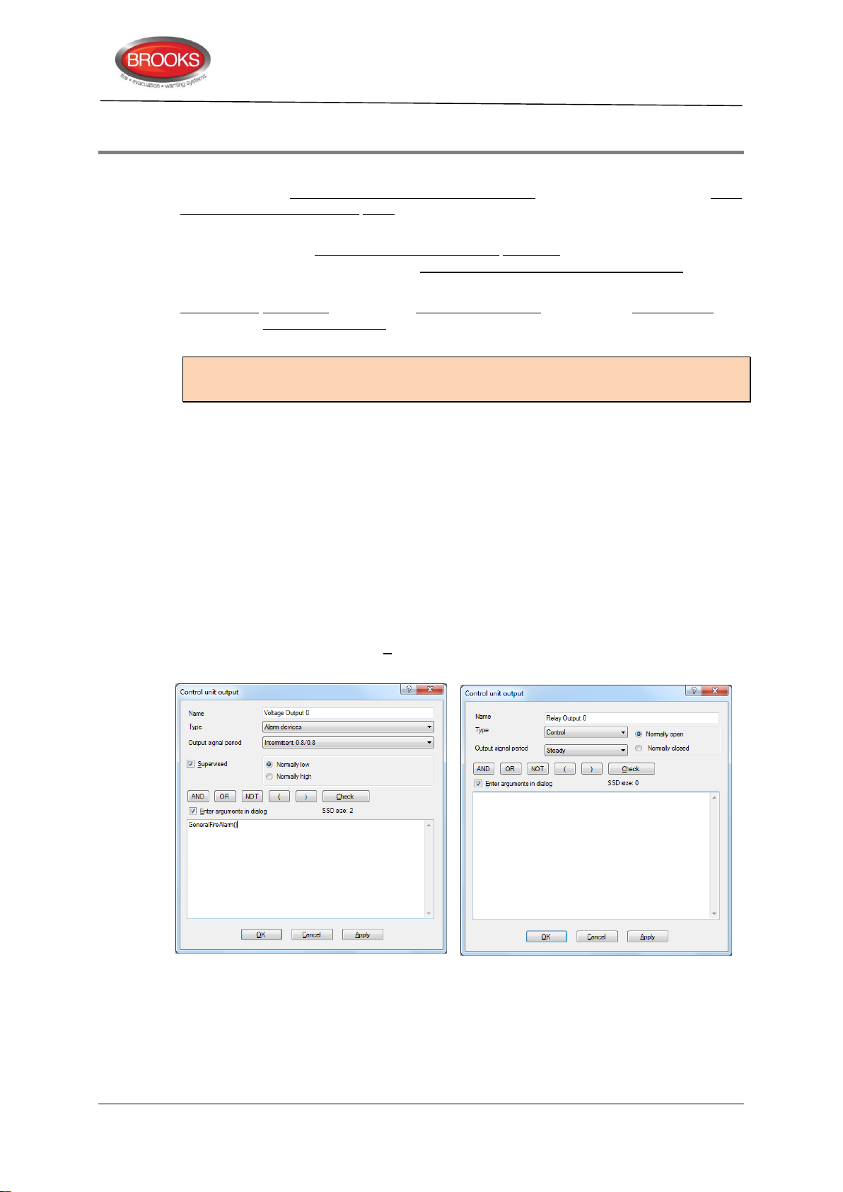
9 Programmable Outputs
FT128 has two programmable voltage outputs (S0-S1) and one programmable relay output
(R0). One or two 8 relay outputs expansion boards 4581 can be mounted in FT128. Input
and Output expansion board 4583 with three programmable outputs (Output 0-2) can also
be mounted in FT128. See “Expansion Boards ” page 22.
On the COM loop, an Addressable Multipurpose I/O unit 3361 with two programmable relay
outputs (Re0 and Re1) per unit and Addressable 2 voltage outputs unit 3364 with two
programmable voltage outputs (VO0 and VO1) per unit can be connected.
Addressable siren 4477, Addressable sounder base 3379, Addressable beacon 4380 and
Addressable Light indicator 4383 can also be connected on the COM loop, i.e. these units
have no physical output, only a siren, sounder and light respectively.
Notes: Units type 3379 + 4477 (or old type 3377) = maximum 50.
Units type 4380 = maximum 10
Each output is programmed (via EBLWin), when applicable for the following:
Name (Normally not changed)
Type
Technical / Programming Manual
FT128 Rev 2.2
Signal period (continuous, pulse, delay, etc.)
Logic (NO / normally low or NC / normally high)
Supervised / Non-Supervised (The voltage outputs in FT128 and in the
Addressable 2 voltage outputs unit 3364)
Control expression (with one or more trigger conditions)
If Enter arguments in dialog is selected, a separate dialog box is opened for easier
entering of the required data (e.g. zone, address, etc.). SSD size indicates how big the
control expression is. It must be < 80.
Figure 27 EBLWin "Voltage" & "Relay” Output Dialog Boxes Respectively
Each 4477 and 3379 unit is programmed via EBLWin for the following:
Technical address
Name (Normally not changed)
Priority level (High / Medium / Low)
77
Page 78
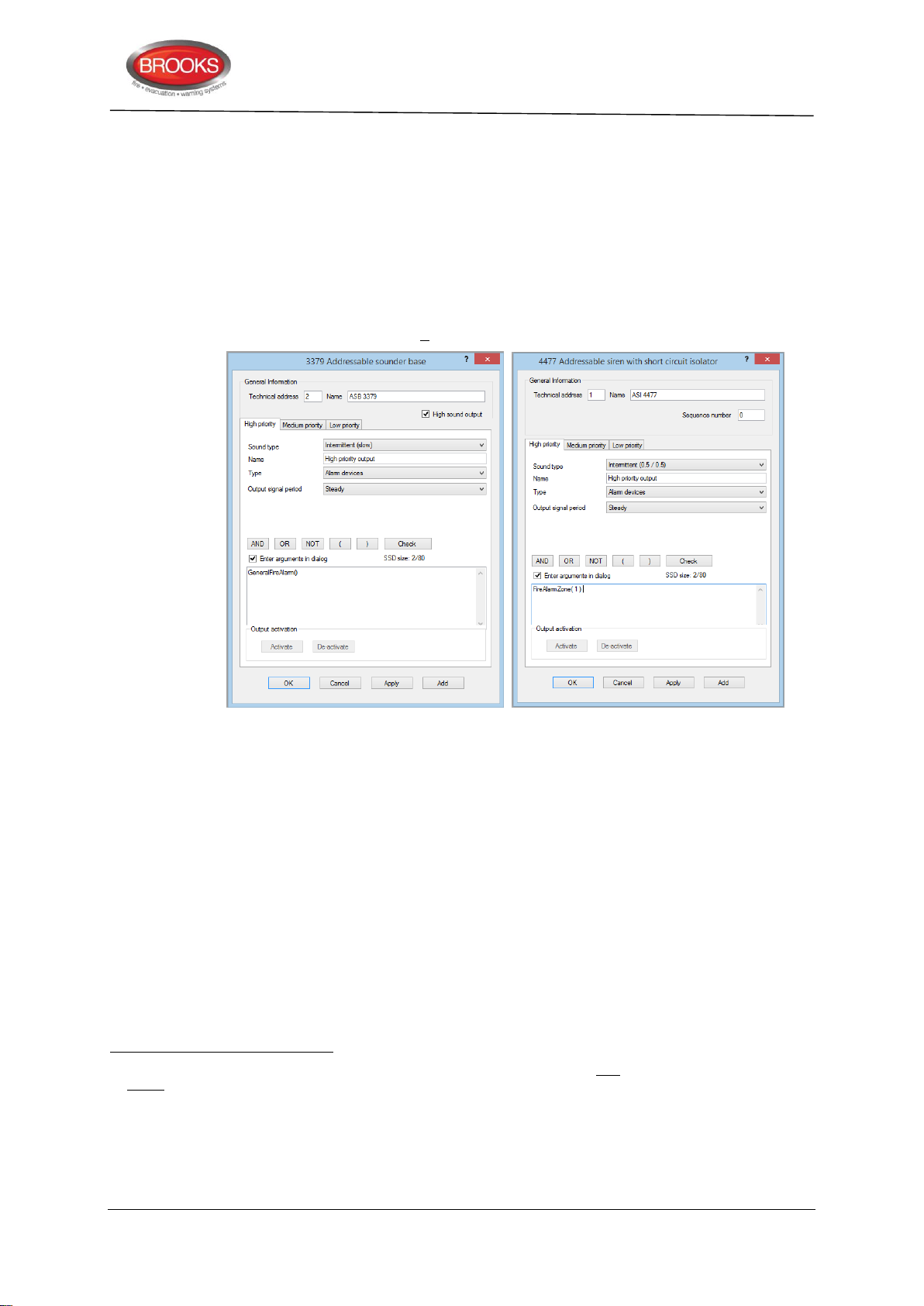
Technical / Programming Manual
78
77
78
79
FT128 Rev 2.2
For each priority level:
Sound type (different for each priority level)
Name
Type (Normally "Alarm device")
Output signal period (Normally "Steady")
Control expression (with one or more trigger conditions)
If Enter arguments in dialog is selected, a separate dialog box is opened for easier
entering of the required data (e.g. zone, address, etc.). SSD size indicates how big the
control expression is. It must be < 80.
Figure 28 EBLWin 3379 and 4477 Dialog Box
Output test
When a PC is connected to FT128, EBLWin open and you are logged on, each output can
be tested for activation / de-activation.
9.1 Control Unit Outputs S0 – S1
FT128 has two programmable, supervised (monitored)77 voltage outputs:
S0 Supervised voltage output, 24V
S179 Supervised voltage output, 24V
By default S0-S1 are set to type "Alarm device", "Intermittent 0.8 / 0.8, normally low,
supervised and trigger condition "General fire".
For connections and more information, see drawing F665.
Supervised as default but via EBLWin it is possible to set each output individually as non-supervised. A normally high output
cannot be supervised.
Supervised outputs have to be calibrated via menu H5/A1, see the FT128 Operation Manual. 1-5 supervision resistors 33K can
be used. The calibrated value has to be in the range 4K7-50K. A fault will be generated for a value outside this range. A
normally high output will be low for a few seconds during restart of FT128.
See Table 1 page 15 regarding system voltage.
S1 is also used to drive an ancillary relay on the FT128 termination board, refer to “FT128 External Termination”, page 29
, maximum 500 mA (Fuse F8).
DC
78
, maximum 200 mA (Fuse F6).
DC
78
Page 79

Technical / Programming Manual
80
81
FT128 Rev 2.2
9.2 Control Unit Output R0
FT128 has one programmable relay output:
R0 Relay output, N/O or N/C contacts80 programmable.
By default R0 is set to type "Routing equipment" (Fire brigade TX), Steady (cont.), normally
open and trigger condition "Fire brigade TX".
For connections and more information, see drawing F665.
9.3 8 Relay Outputs Expansion Board 4581 Output 0 – Output 7
Each 4581 board has eight programmable relay outputs:
Output 0 Relay output, N/O or N/C contacts programmable
Output 1 Relay output, N/O or N/C contacts programmable
Output 2 Relay output, N/O or N/C contacts programmable
Output 3 Relay output, N/O or N/C contacts programmable
Output 4 Relay output, N/O or N/C contacts programmable
Output 5 Relay output, N/O or N/C contacts programmable
Output 6 Relay output, N/O or N/C contacts programmable
Output 7 Relay output, N/O or N/C contacts programmable
Relay contact ratings: Max. 2A @ 30 VDC.
For connections and more information, see dwg. F665.
9.4 Inputs and Outputs expansion board 4583 Output 0–1
Expansion board 4583 has two programmable, supervised
Output 0 Supervised voltage output, 24V
Output 1 Supervised voltage output, 24V
DC
DC
77
voltage outputs:
78
, maximum 200 mA (Fuse F1).
78
, maximum 200 mA (Fuse F2).
For connections and more information, see drawing F731.
See also chapter “Inputs and Outputs Expansion Board 4583”, page 26.
9.5 3361 Unit Outputs Re0 – Re1
Each 3361 unit has two programmable relay outputs:
Re0 Relay output, N/O or N/C contacts programmable
Re1 Relay output, N/O or N/C contacts programmable
Relay contacts: maximum 2 A @ 30 VDC / 125 VAC
Connections and more information, see drawings F735.
9.6 3364 Unit Outputs VO0, VO1 & VO2
Each 3364 unit has two programmable, supervised voltage outputs77:
VO0 Supervised voltage output, 24VDC, maximum 1A81
VO1 Supervised voltage output, 24VDC, maximum 1A81
VO2 voltage output, 24VDC, max. 1A81, intended for fire door closing. Normally high.
Relay contacts: maximum 1 A @ 30 VDC.
Cont. 1 A, during 10 ms 1.4 A.
79
Page 80

VO0-VO1 are set to outputs for "alarm device" by default.
82
83
24 VDC required from an external power supply unit (e.g. 3366AU).
Connections and more information see drawing F737.
9.7 The 4477 Unit Output (Siren)
Each unit has one programmable output:
Output Siren, with two priority levels and three sound types.
Connections and more information, see drawing F665 & F729.
9.8 The 3379 Unit Output (Sounder)
Each 3379 unit has one programmable output:
Output Sounder, with three priority levels and three sound types.
Also "High sound output" can be selected (4.5 dB).
Connections and more information, see drawing F665 & F729.
9.9 The 4380 unit output (beacon)82
Technical / Programming Manual
FT128 Rev 2.2
Each 4380 (under Obsolete Loop Units) unit has one programmable output:
Output Beacon
Connection is similar to other COM loop units as shown in drawing F729.
9.10 The 4383 unit output (Light indicator)83
Each 4383 unit has one programmable output:
Output Light indicator
Connections and more information, see drawing F729.
The unit is discontinued and will be replaced with a new strobe approved to EN54.23.
4383 is discontinued, it is not complying with the new standard EN54.23 however the unit still can be used in the AU or NZ
markets until a compliant unit is released.
80
Page 81

10 Output Programming
84
85
86
87
88
Output programming is done via EBLWin. See the EBLWin dialog box.
10.1 Type of output
The following types are available (see also comments below):
1. Control
2. Fire Ventilation
3. Extinguishing
4. Alarm Device
5. Routing Equipment (Fire brigade TX)
6. Control, neutral
7. Interlocking Output
10.1.1 Comments to the types
Technical / Programming Manual
FT128 Rev 2.2
1. Default. General (normal) control output84
2. Used to activate fire ventilation equipment85
3. Used to activate extinguishing equipment86
4. Used for OWS or sounders, etc.87
5. Used for fire brigade TX outputs only88
6. General (normal control output. No collective disablement and no LED indication.
7. Output used together with a corresponding interlocking input. See chapter
"Interlocking Function”, page 94. Activated outputs are shown in menu H9/C1.
10.2 Logic
The logic is set in the EBLWin dialog box "Voltage or Relay Output".
(•) Normally Open / low normally open relay contact or normally low voltage output.
( ) Normally Closed/high normally closed contact or normally high voltage output
(24VDC).
10.3 Supervised / Non-supervised
A voltage output is normally supervised (default). By unmarking this checkbox the voltage
output will be not supervised.
Note: A normally high output cannot be supervised.
Collectively disabled via menu H2/B4 (all control outputs). Re-enabled via menu H2/B8.
Collectively disabled via menu H2/B4 (all ventilation outputs). Re-enabled via menu H2/B8. LED "Ventilation" is indicating
activated output.
Collectively disabled via menu H2/B4 (all extinguishing outputs). Re-enabled via menu H2/B8. LED "Extinguishing" is indicating
activated output.
Collectively disabled / re-enabled via menu H2/B9 (all alarm device outputs). Controlled by push button "Silence alarm devices".
Fault on / disabled output is indicated by LED "Fault / Disablements Alarm devices" blinking (fault) / continuous (disablement).
Disabled / Re-enabled via menu H2/B10 (Fire and/or fault outputs). Controlled via open door (if programmed so). Used together
with trigger condition Fire brigade TX. LED "Fire brigade TX" is indicating activated output. (Fire brigade TX feedback via a
programmable input can light up the LED instead). Fault on / disabled output is indicated by LED "Fault / Disablements Fire
brigade TX" blinking (fault) / continuous (disablement).
81
Page 82
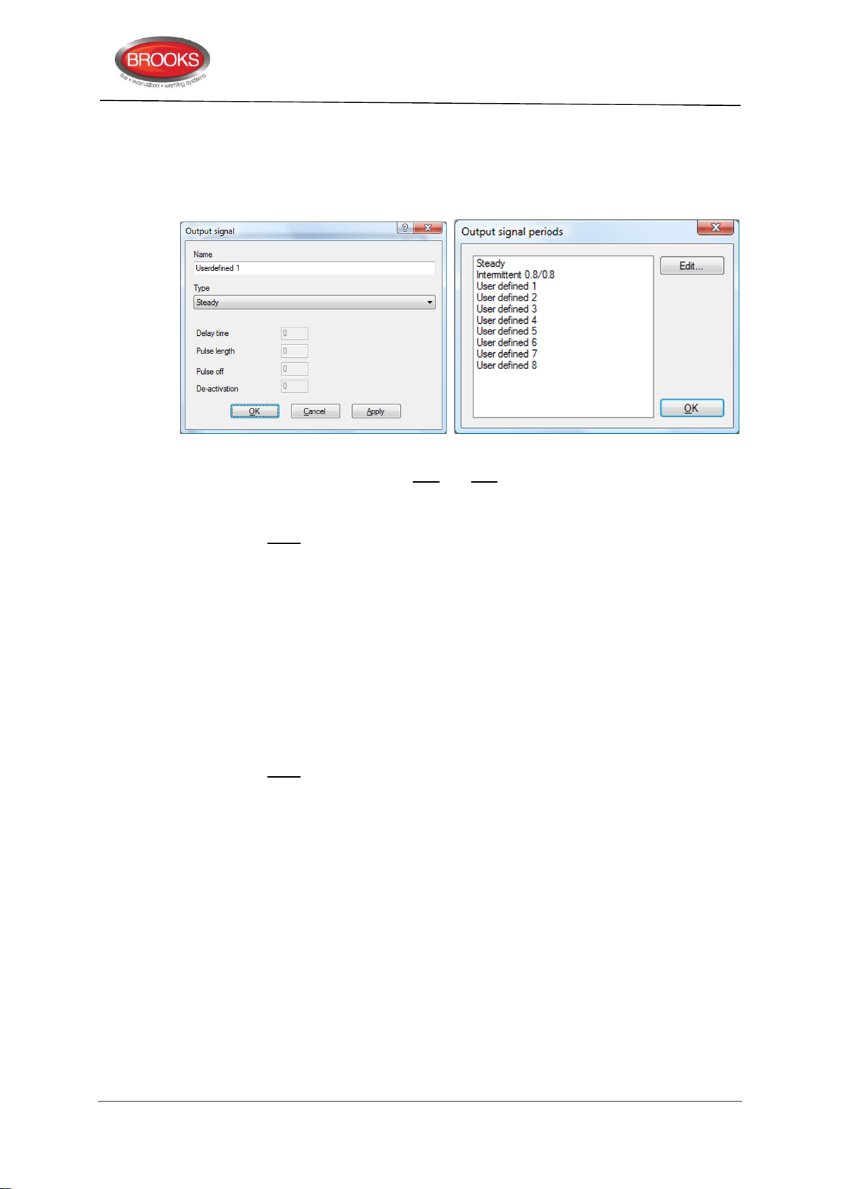
See also chapter "Programmable Voltage Outputs (S0-S1)”, page 19.
10.4 Output Signal Period
Each output uses an "Output signal period", which controls the output's activation. The
following are available:
Technical / Programming Manual
FT128 Rev 2.2
User defined 1-8 can be built up with type and time.
10.4.1 Types of output signal periods
The following types are available:
1. Steady (continuous)
2. Intermittent
3. One pulse
4. Steady Delayed Activation
5. Intermittent Delayed Activation
6. One pulse Delayed Activation
7. Steady Delayed De-Activation
10.4.2 Timing of output signal periods
The following times are available:
Delay time (when required)
Pulse length time (when required)
Pulse off time (when required)
De-activation time (when required)
See also Figure 29 below.
82
Page 83
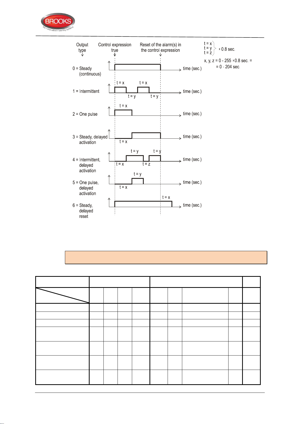
Technical / Programming Manual
In FT128
COM loop units
Output
Type
S0-S1
R0
4581
board
4583
board
I/O unit
3361
Unit
3364
Siren, S/B & Beacon
& Light indicator 4477,
3379, 4380 & 4383
4582
board
Inter
locking
1 Steady (continuous)
X X X X X
X X X
X
2 Intermittent
X X XXX
--
--
XX
--
--
--
3 One pulse
X X XXX
--
--
--
--
--
--
4 Steady (continuous),
delayed activation
X X X X X
X
X
X
X
5 Intermittent, delayed
activation
X X
XXX -- -- XX
--
-- --
6 One pulse, delayed
activation
X X
XXX -- -- --
--
-- --
7 Steady (continuous),
delayed de-activation
X X X X X
X
X
X
--
FT128 Rev 2.2
Figure 29 Signal Output Periods
Delay time, Pulse length, Pulse off and/or De-Activation, have to be set for the "Signal
period" respectively. For types 2 & 5, the x and y times must be equal and maximum 5.6s.
For types 3 & 6 the x time must be maximum 5.6s.
Note: The different types can be used together with the different outputs according to
Table 12 below
Table 12 Output signal period for the programmable output
83
Page 84
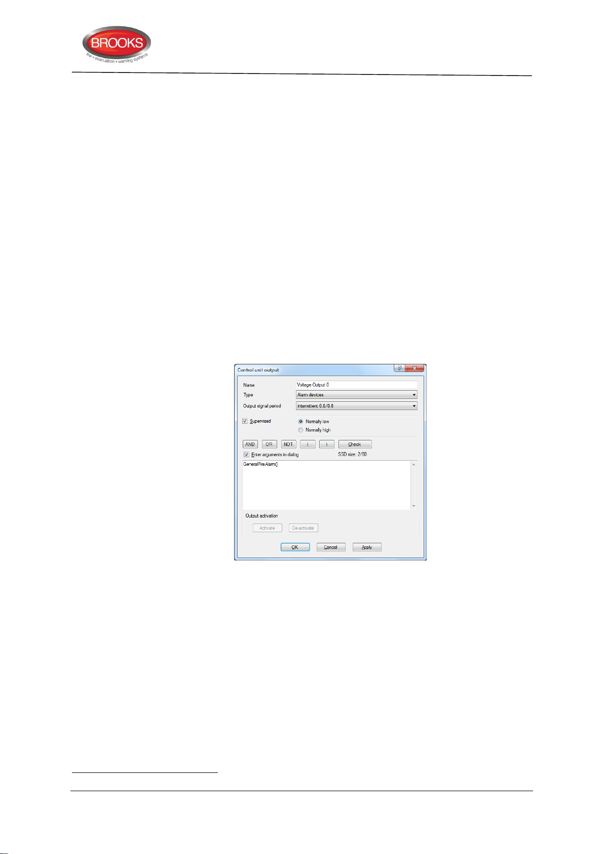
The types that can be used in the "Output Signal period" for the programmable output
89
respectively are:
X = Output type can be used.
XX = Output type can be used but only 0.8s/0.8s.
XXX = Output type can be used but maximum 5.6s/5.6s and the pulse maximum 5.6s
respectively.
10.5 Control Expression
Each programmable output has to be given a control expression 89. It is created by using
Boolean algebra.
If an output is to be used for manual control only e.g. an AS1668 fan control output or an
output controlled by input trigger condition “Activate output”, a “never true” control
expression must be programmed. In such a case, control expression
“TimeChannelActivated” (Always off) can be used.
Trigger conditions (see "Available functions"), logical "Operators" (AND, OR, NOT) and
parentheses are used to build up a "control expression" containing up to 40 trigger
conditions. See also chapter "Control Expression Examples”, page 90.
A programmable output will be activated as long as its control expression is true.
Technical / Programming Manual
FT128 Rev 2.2
Figure 30 Control expression output dialog box
In any output dialog box, click the right mouse button in the large white field. Select
Alarm, Interlocking, Disablement or Other to open a "Trigger conditions list". Depending
on the selected trigger condition, different arguments / data have to be entered. In Figure
30, the trigger
condition "General Fire Alarm" is selected.
10.5.1 Trigger Conditions
Some trigger conditions require additional information, see below information within
parentheses (nnnnn) after the trigger condition respectively.
The trigger conditions are divided into four groups as follows:
Alarm
Interlocking
A programmable output with no control expression will be interpreted by the CIE. as if it does not exist.
84
Page 85

Disablement
Other
The numbering of the trigger conditions is only for "the comments to the trigger conditions"
below:
10.5.1.1 Alarm
1. Fire Alarm Zone (+Zone no.)
2. Fire Alarm Zone Address (+Zone no.+Address)
3. General Fire Alarm
4. Consecutive Fire Alarm (sequence) (+start Zone no. and address +stop Zone
5. Pre Warning Zone (+Zone no.)
6. Pre Warning Zone Address (+Zone no.+Address)
7. General Pre Warning
8. Consecutive Pre Warning (+start Zone no. and address +stop Zone no. and
Technical / Programming Manual
FT128 Rev 2.2
no. and address + Quantity)
address + Quantity)
9. Heavy Smoke Alarm Zone (+Zone no.)
10. Heavy Smoke Alarm Zone Address (+Zone no. + Address)
11. General Heavy Smoke Alarm
12. Consecutive Heavy Smoke Alarm (sequence) (+start Zone no. and address
+stop Zone no. and address +Quantity)
13. Two Address Dependent Fire Alarm (+Zone no. +Address)
14. Two Zone Dependent Fire Alarm (+Zone no.)
15. Multiple Detector Alarm
16. One Detector Alarm
17. Key Cabinet Alarm
18. AAF Zone Alarm (+AAF Zone no.)
19. Quiet Alarm Zone (+Zone no.)
20. Quiet Alarm Zone Address (+Zone no. +Address)
21. General Fire Alarm Reset
22. Delayed Alarm Zone Address (+Zone no. +Address)
23. Delayed Alarm Zone (+Zone no.)
24. General Delayed Alarm
25. First Zone In Alarm Control Unit (+Zone no. +Control Unit no.)
26. First Zone In Alarm Zone Group (+Zone no. +Zone Group name)
27. Pre Warning Zone Group (+Zone Group name +Quantity)
28. Fire Alarm Zone Group (+Zone Group name +Quantity)
29. Heavy Smoke Alarm Zone Group (+Zone Group name +Quantity)
10.5.1.2 Interlocking
30. Interlocking Input Area Activated (+Area no.)
31. Interlocking Input Area Point Activated (+Area no. +Point)
85
Page 86

32. General Interlocking Input Activated
33. Consecutive Interlocking Input Activated (sequence) (+start Area no. and
point +stop Area no. and point +Quantity)
10.5.1.3 Disablement
34. Fire Brigade Tx Disabled
35. Zone Disabled (+Zone no.)
36. Zone Address Disabled (+Zone no. +Address)
37. General Zone Address Disabled
38. All Control Disabled
39. All Alarm Devices Disabled
40. Control Disabled Control Unit (+Control Unit)
41. Alarm Device Disabled Control Unit (+Control Unit)
42. General Disablement
10.5.1.4 Other
Technical / Programming Manual
FT128 Rev 2.2
43. Indication Fire Brigade TX Activated
44. Indication Fault TX Activated
45. General Fault
46. General Mains Fault
47. Reset Pulse Zone Address (+Zone no. +Address)
48. Time Channel Activated (+Time channel name / no.)
49. Alert Annunciation Activated
50. Alert Annunciation Acknowledged
51. Door Open
52. Fire Door Closing (+Zone no. +Address)
53. General Service Signal
54. Fire brigade TX
55. Door Open Control Unit (+Control Unit)
56. Extinguishing System Fault
57. Extinguishing System Released
58. Activated Key Cabinet
59. Fault Control Unit (+Control Unit)
60. Consecutive Fault Control Unit (+start Control Unit and stop Control Unit)
61. Zone Fault (+Zone no.)
62. External Fault (+ext. fault)
63. Technical Warning (+techn. warning)
64. General Technical Warning
86
Page 87

Technical / Programming Manual
90
91
10.5.1.5 Comments to the Trigger Conditions (Functions):
Alarm
1. Fire alarm. For more information regarding fire alarm, see FT128 Operation
Manual. Output is activated when the specified Zone is in alarm.
2. See 1. Output is activated when the specified alarm point is in alarm.
3. See 1. Output is activated when any alarm point or Zone is in alarm.
4. See 1. Quantity (1-9): "1" means one unit in alarm is required, "2" means two units
in alarm are required to activate the output and so on.
5. Pre-warning.90 Output is activated when the specified Zone exceeds the prewarning level. For more information regarding pre-warning, see FT128 Operation
Manual.
6. See 5. Output is activated when the specified alarm point exceeds the pre-warning
level.
7. See 5. Output is activated when any alarm point or Zone exceeds the pre-warning
level.
8. See 5. See also 4 above regarding "Quantity".
9. Heavy smoke / heat alarm. Output is activated when the specified Zone exceeds
the heavy smoke / heat level. For more information regarding heavy smoke / heat
alarm, see FT128 Operation Manual.
FT128 Rev 2.2
10. See 9. Output is activated when the specified alarm point exceeds the heavy
smoke / heat level.
11. See 9. Output is activated when any alarm point exceeds the heavy smoke /
heat level.
12. See 9. See also 4 above regarding "Quantity".
13. Output is activated when only one address (in two- address dependence) is in fire
alarm state. For more information, see FT128 Operation Manual.
14. Output is activated when only one zone (in two-zone dependence) is in fire alarm
state. For more information, see FT128 Operation Manual.
15. Output activated when "Multiple detector alarm" is true, i.e. Fire Alarm Type A91.
16. Output activated when "One detector alarm" is true, i.e. Fire Alarm Type B91.
17. General Key cabinet alarm activated. For more information, see FT128 Operation
Manual.
18. Alarm Acknowledgement Facility, requires Alarm Acknowledgement Module
AAM. "Alarm" is activated in the specified AAF zone. Panasonic new Local Alarm
Acknowledgment (LAA) is typically Brooks AAM.
19. Output activated for any "Quiet alarm" in the specified zone. Normally used in
AS1668 fire fan applications or as a non-latching / non-brigade call detector.
20. Output activated for one specified "Quiet alarm" in the specified zone-address.
Used in AS1668 fire fan control applications.
21. This control expression is true (i.e. output activated) for 15 seconds after the last
alarm is reset.
22. Output of specified Zone-Address is activated for predetermined time (set in
EBLWin system properties). Typical application when a smoke detector is
The trigger condition is true as long as the pre-warning level is exceeded. It is also true as long as the fire alarm level is exceeded
even if the option pre-warning detection is disabled (via EBLWin).
See Section ”Fire Alarm Type A and Fire Alarm Type B”, page 115.
87
Page 88

Technical / Programming Manual
92
93
94
FT128 Rev 2.2
programmed to activate 3379. If the smoke is cleared during the delay time, the
sounder base will de-activate otherwise, a general alarm in FT128 will be activated.
23. Same as 22 but for specified zone
24. Same as 22 but for any Zone or Zone-Address in the system..)
25. Output is activated only if the first alarm is an alarm in the specified Zone in the
specified Control Unit. NOTE! This is not valid for manual call points.
26. Output is activated only if the first alarm is an alarm in the specified Zone in the
specified Zone Group.
27. Pre-warning, Output is activated when any of the alarm points in the specified Zone
Group exceeds the pre-warning level. See also 4. Above regarding the quantity.
For information refer to the FT128 Operation Manual.
28. Fire alarm, Output is activated when any of the alarm points in the specified Zone
Group is in alarm. See also 4. Above regarding the quantity. For information refer
to the FT128 Operation Manual.
29. Heavy smoke / heat alarm, Output is activated when any of the alarm points in the
specified Zone Group exceeds the heavy smoke / heat alarm level. See also 4.
Above regarding the quantity. For information refer to the FT128 Operation Manual.
Interlocking
30. Output activated when one or more interlocking inputs, in the specified interlocking
area, are activated.
31. Output activated when the interlocking input, in the specified interlocking
area/point, is activated.
32. Output activated when any interlocking input is activated.
33. Output activated when interlocking inputs, in the specified range, are activated
(from interlocking area no. / point to interlocking area no. / point). See also 4 above
regarding "Quantity".
Disablement
34. Output activated when any Routing equipment output (Fire brigade TX) is
disabled92.
35. Output activated when the specified zone is disabled93.
36. Output activated when the specified alarm point (zone- address) is disabled93.
37. Output activated when any alarm point (zone-address) or zone is disabled 93.
38. The control expression is true (output activated) when all control outputs of the
types Control, Fire ventilation and Extinguishing are disabled via menu
H2/B493. This output has to be type Control – neutral.
39. The control expression is true (output activated) when all control outputs of type
Alarm device are disabled via menu H2/B994. This output must be type Alarm
devices.
40. The control expression is true (output activated) when all control outputs of the
types Control, Fire ventilation and Extinguishing are disabled via menu
H2/B493. This output has to be type Control – neutral.
41. The control expression is true (output activated) when all control outputs of type
Alarm device are disabled via menu H2/B9). This output has to be type Alarm
devices.
Which is indicated by LED Fault / Disablements "Fire brigade TX".
Which is indicated by LED Fault /Disablements "General Disablements".
Which is indicated by LED Fault / Disablements "Alarm devices".
88
Page 89

Technical / Programming Manual
100
95
96
97
98
99
100
FT128 Rev 2.2
42. The control expression is true (output activated) when any disablement exists
in the system93.
Other
43. The control expression is true (output activated) when LED "Fire brigade TX" is lit,
i.e. when any "Fire brigade TX" output is activated (default) or when a
programmable input with trigger condition "Activated Routing Equipment" is
activated95.
44. The control expression is true (output activated) when LED "Fault TX activated" is
lit, i.e. when the routing equipment output (Fault TX) is activated96.
45. Output activated when one or more faults are generated in the system97.
46. Output activated for loss of mains (in the CIE or external power supply 3366AU).
Note: The output(s) will be activated immediately but the corresponding fault is
normally delayed (set via EBLWin).
47. The control expression is true (output activated) for 5 seconds, whenever a reset
pulse is sent to the specified Zone-Address.
48. Output activated when the specified time channel is activated.
49. Output activated when Alert annunciation alarm is activated (by any alarm point
set to activate this function)98. For more information, see FT128 Operation Manual.
50. Output activated when Alert annunciation alarm is activated (by any alarm point
set to activate this function) 98 and acknowledged. For more information, see FT128
Operation Manual.
51. Output activated for Door open in the FT128 99.
52. This trigger condition plus the OR operator has to be used for each detector (ZoneAddress) controlling a fire door (normally > two detectors). Type of output is
normally "Control, neutral". See Fire Door Closing Function, page 99.
53. Output activated when Service signal is activated (by any sensor)
.
54. The control expression is true (output activated) when the control unit standard
output "Fire brigade TX" is activated.
Note: Normally used with output type Routing equipment (Fire brigade TX).
55. Output activated for Door open in the control unit99.
56. Output activated when input trigger condition "Extinguishing system fault" is true.
57. Output activated when input trigger condition "Extinguishing system released" is
true.
58. Output activated when input trigger condition "Activated key cabinet" is true.
59. Output activated when one or more faults are generated in the control unit97
60. Output activated when one or more faults are generated in the control unit97.
61. Output activated when one or more faults are generated in the specified Zone97.
62. Output activated when the specified external fault is generated97.
This output will also be activated when the routing equipment test is performed via menu H1. This trigger condition must not
be used for type of output "Routing equipment (Fire brigade TX)".
Which is indicated by LED Routing equipment "Fault TX activated". This output will also be activated when the routing
equipment test is performed via menu H1.
Which is indicated by LED Fault / Disablements "General fault" and/or LED Routing equipment "Fault TX activated".
Valid until the AA alarm is reset or becomes a normal fire alarm.
Which is indicated by the LED "Door open" in the CIE
Indicated by the LED "Service" in the CIE
89
Page 90

Technical / Programming Manual
101
101
a b c y 0 0 0
0
0 0 1
0
0 1 0
0
0 1 1
0
1 0 0
0
1 0 1 0 1 1 0 0 1 1 1
1
a b c y 0 0 0 0 0 0 1 1 0 1 0 1 0 1 1
1
1 0 0
1
1 0 1 1 1 1 0
1
1 1 1
1
a b c y 0 0 0 0 0 0 1 1 0 1 0
0
0 1 1
0
1 0 0 1 1 0 1
1
1 1 0
1
1 1 1
1
FT128 Rev 2.2
63. Output activated when the specified technical warning is generated
64. Output activated when one or more technical warnings are generated.
10.6 Logical Operators
The logical operators available in EBLWin are in the following priority order:
( ) parentheses, changes priority order
NOT not-function (inverts), is written NOT in EBLWin
AND and-function, is written AND in EBLWin
OR or-function, is written OR in EBLWin
10.6.1 Control Expression Examples
In order to understand how to create control expressions, here follow some AND, OR, NOT
and ( ) examples and also some control expression examples.
10.6.1.1 AND
a AND b AND c=y
y is true (=1) when all the conditions a, b, c are true, i.e. a=1 and b=1
and c=1 makes y=1. All other combinations makes y=0.
This is also shown in the truth table:
.
10.6.1.2 OR
a OR b OR c=y
y is true if at least one of the conditions a, b, c is true, i.e. a=1 or b=1
or c=1 makes y=1.
This is also shown in the truth table:
10.6.1.3 NOT
Inverts a condition, e.g. NOT b = NOT 0 = 1.
A OR NOT b AND c =y
This is shown in the truth table:
Indicated by a blinking [i] in the CIE display.
90
Page 91

10.6.1.4 Parentheses
a b c
y
0 0 0 1 0 0 1 1 0 1 0 1 0 1 1 0 1 0 0 1 1 0 1
1
1 1 0
1
1 1 1
1
Changes priority order.
a OR NOT (b AND c)=y (This is same as the previous but completed
with parentheses.)
This is shown in the truth table:
10.6.1.5 Control Expressions
The AND operator has priority, i.e. a AND b OR c = (a AND b) OR c. This is perhaps more
obvious if you write it: a · b + c.
NOTE! a AND b OR c ≠ a AND (b OR c).
Here follows some examples (and explanations) to show the principles how to build a
control expression with "conditions" and logical operators:
Example 1
Output: Voltage output S0
Control expression: Pre Warning Zone (10)
Technical / Programming Manual
FT128 Rev 2.2
Explanation: Pre-warning activated in zone 10 will activate the output S0.
Example 2
Output: Relay output R0
Control expression: General Control disabled AND NOT Door Open
Explanation: Controls disabled via menu H2/B7 will activate the output R0
when the door in FT128 is not open (i.e. closed).
Example 3
Output: Voltage output VO0
Control expression: Fire Alarm Zone (23) AND Fire Alarm Zone (24) AND NOT
General Fault
Explanation: Fire alarm activated in zone 23 and zone 24 will activate the
output VO0 when there are one or more faults in the system at
the same time.
Example 4
Output: Voltage output S1
Control expression: Consecutive Fire Alarm (10,10,10,19,1) OR Consecutive Fire
Alarm (10,21,10,40,1)
Explanation: Fire alarm activated by one of the alarm points in zone 10
addresses 10-19 or by one of the alarm points in zone 10
addresses 21-40 will activate the output S1 (i.e. the alarm point
in zone 10 address 20 will not activate the output S1).
91
Page 92
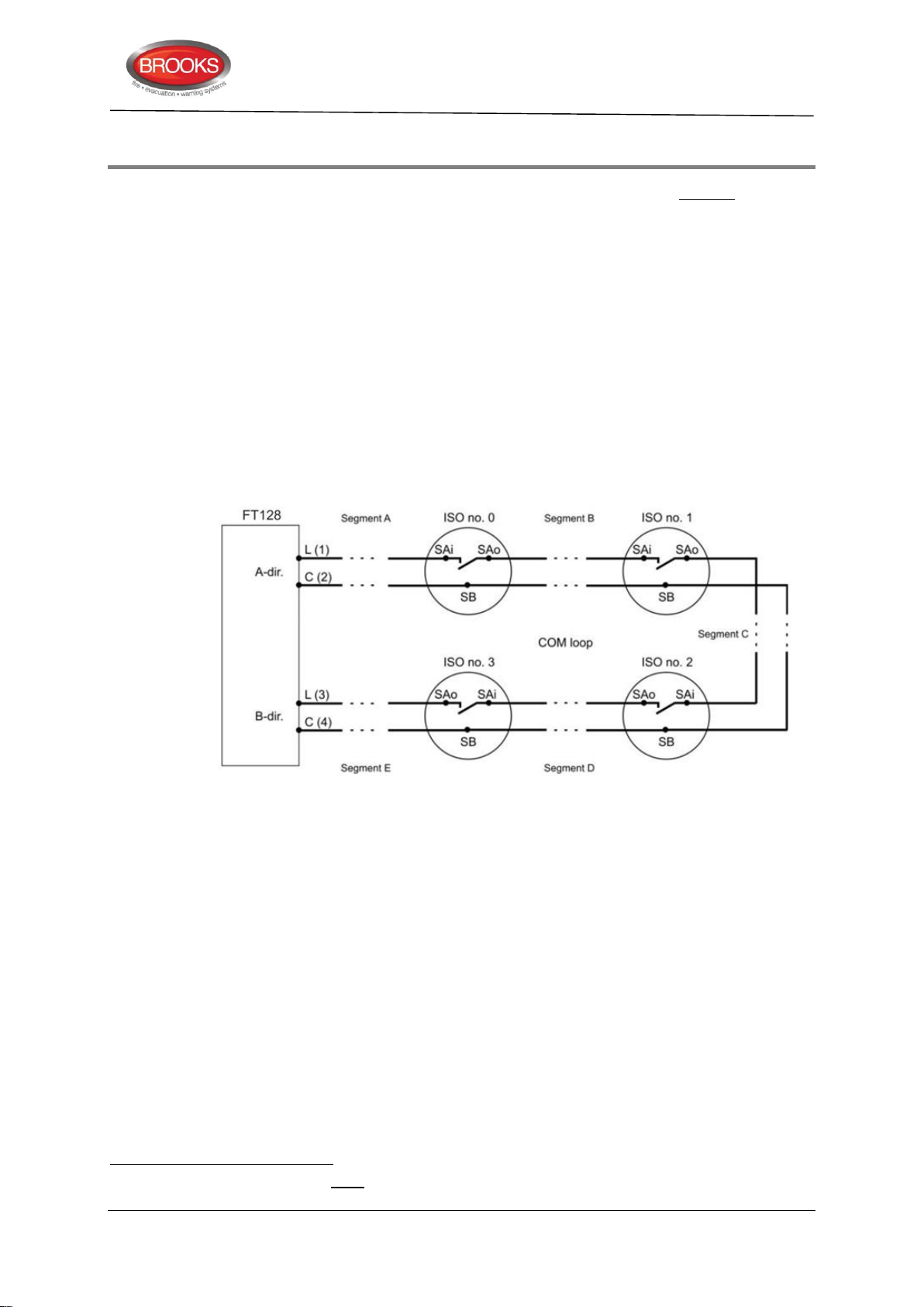
11 Short Circuit Isolators
102
103
102
103
4313 Analogue base with isolator has built-in short circuit isolator that requires a separate
COM loop address and a Sequence Number, 00-63.
The units 4433, 4439 and 4477 have built-in isolator that do not require any separate COM
loop address, only a Sequence Number, 00-63. As an option, these units can be used
without the isolator in function. If so, they have to be programmed in EBLWin as if they
were 3333, 3339 and 3377 units and via the address setting tool 4313/4413 set to 2330
mode instead of NORMAL mode.
An open circuit (break) or short circuit on the COM loop has to generate a fault in the control
unit within 60-100 seconds.
If one or more Short Circuit Isolators are used
(i.e. the part between two Short Circuit Isolators or between the control unit and one Short
Circuit Isolator). Only the affected segment will be isolated, which will minimise the number
of units disabled by a short circuit.
The fault messages will also show between which isolators the short circuit is situated.
Technical / Programming Manual
FT128 Rev 2.2
, the loop will be divided into "segments"
Figure 31 Short Circuit Isolators example in FT128
The first isolator (ISO) in the A-direction must have the sequence no. 0 (ISO no. 0), the
next sequence is no. 1 (ISO no. 1) and so on. The sequence no. is programmed via
EBLWin.
If no Short Circuit Isolators are used, the whole COM loop will be disabled in case of short
circuit on the loop.
As from version 2.1.x, the communication (and power supply) direction will alternate every
22 seconds.
COM loop end-point voltage
<12 VDC or COM loop short circuit or COM loop
break(s):
This will start a "cycle" as follows.
The whole loop will be disabled, i.e. no voltage on the loop which means that all
isolator relays will be powered down (= all isolators disabled), i.e. there will be a
“break” on the L (SA) wire in each isolator.
A control unit algorithm will now try to re-enable the first isolator in the A-direction
(ISO no. 0 / sequence no. 0). If this is possible, the next isolator in the A-direction
At least one short circuit isolator must be install every 40 alarm points as required by AS1670.1.
When communicating in the A-direction.
92
Page 93

Technical / Programming Manual
FT128 Rev 2.2
(ISO no. 1 / sequence no. 1) will be re-enabled, if this is possible, and so on. The
isolator just before a short circuit cannot be re-enabled.
The control unit algorithm will now try to re-enable the first isolator in the B-direction
(ISO no. 3 / sequence no. 3 in Figure 16). If this is possible, the next isolator in the
B-direction will be re-enabled, and so on.
Finally all isolators will be re-enabled except the isolator on each side of a short
circuit and any isolator(s) between two or more breaks on the loop.
Communication will be in both directions for 10 minutes. Then a new “cycle” starts.
If the “fault(s)” are not corrected, the communication will be in both directions for
another 10 minutes when a new “cycle” starts, and so on.
If the “fault(s)” are corrected, the communication will return to be in the A-direction
only.
Depending on if it is too low voltage on the loop, short circuit, one break or two or more
breaks, the fault messages will be different.
FAULT: Cut-off SCI nn <-> SCI nn
nn = A, 00, 01, 02, 03, 04, 05 - - up to 63 or B.
FAULT: Short circuit SCI nn <-> SCI nn
nn = A, 00, 01, 02, 03, 04, 05 - - up to 63 or B.
If there are multiple loop faults, i.e. one or more short circuits and/or one or more Cut-offs,
there will be a “multiple COM loop fault” message.
FAULT: Several faults on COM-loop
The first fault message will show the first fault in the A-direction.
There will always be a “no reply” message for all units not found in spite of communication
in both directions.
FAULT: No reply xx-xx
FAULT: No reply techn address xxx
Regarding Fault acknowledge, see the FT128 Operation Manual.
Note: After the faults are acknowledged it can take up to 10 minutes before the faults will
disappear from the fault list, since the check ("cycle") starts every 10th minute.
93
Page 94
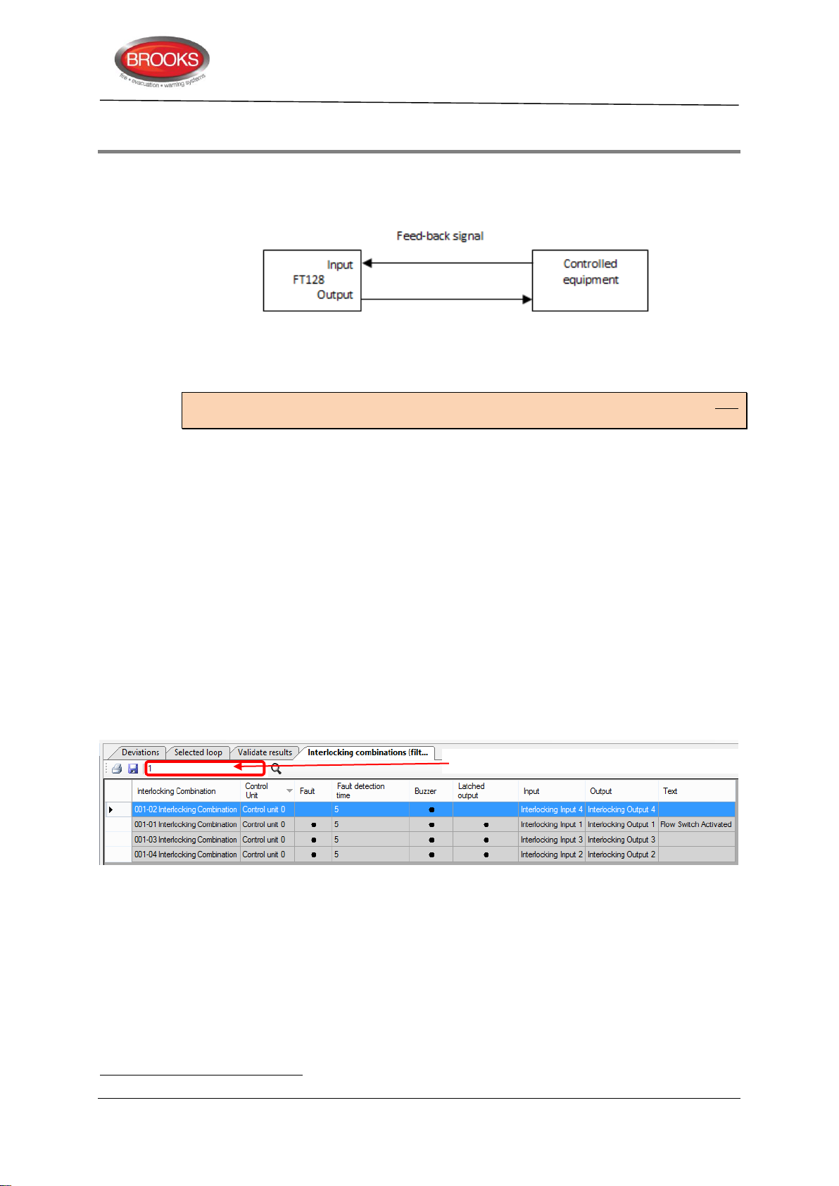
12 Interlocking Function
104
104
Filters the lists of interlocking with anything containing “1”
The interlocking function is used to verify that an output has been activated, i.e. by
"combining" an output with an input (feed-back from the equipment controlled by the
corresponding interlocking output).
12.1 Interlocking Programming
Up to 100 Interlocking Combinations can be programmed using EBLWin.
Note: Each interlocking input and each interlocking output can only be used in one
interlocking combination.
Area and Point fields are unique identifiers for each paired interlocking combination
synonymous to Zone-Address. They are presented in this format NN-NN with the first 2
digits representing the Area and the last 2 digits representing the Point. Both Area and
Point numbers range from 1-99.
Technical / Programming Manual
FT128 Rev 2.2
It is advantageous to have a numbering system planned correlating to the location (“Area”)
when assigning a Name to the interlocking combinations. Having some form of structure
to the numbering will greatly help organise the SSD file and make it easier to understand
and assist with troubleshooting later. One should also consider including all I/O devices
into this numbering structure so that it will be easier to select from the list of interlocking
combinations.
A Filter Function Box as shown in Figure 32 below, is available to assist with listing only
those interlocking combinations of interests. This will become more powerful when some
sort of numbering structure is in place. Figure 32 was from a list of 100 interlocking
combinations, typing in “1”
anything containing “1”. One can see the usefulness of having a planned numbering
structure in place from this example should all interlocking combinations on containing 1
were called for.
Available interlocking inputs and/or outputs will appear in the EBLWin dialog box shown in
Figure 33 page 95, only when each input and output have been configured with Type =
Interlocking
in the filter function box quickly narrows down the lists with
Figure 32 Filter function
12.1.1 Interlocking Output
The "Voltage Output" / "Relay Output" dialog boxes are used to configure the interlocking
output.
Type: "Interlocking" is to be selected.
Filtering search texts are case sensitive. For this reason, ensure that naming convention is consistent throughout.
94
Page 95
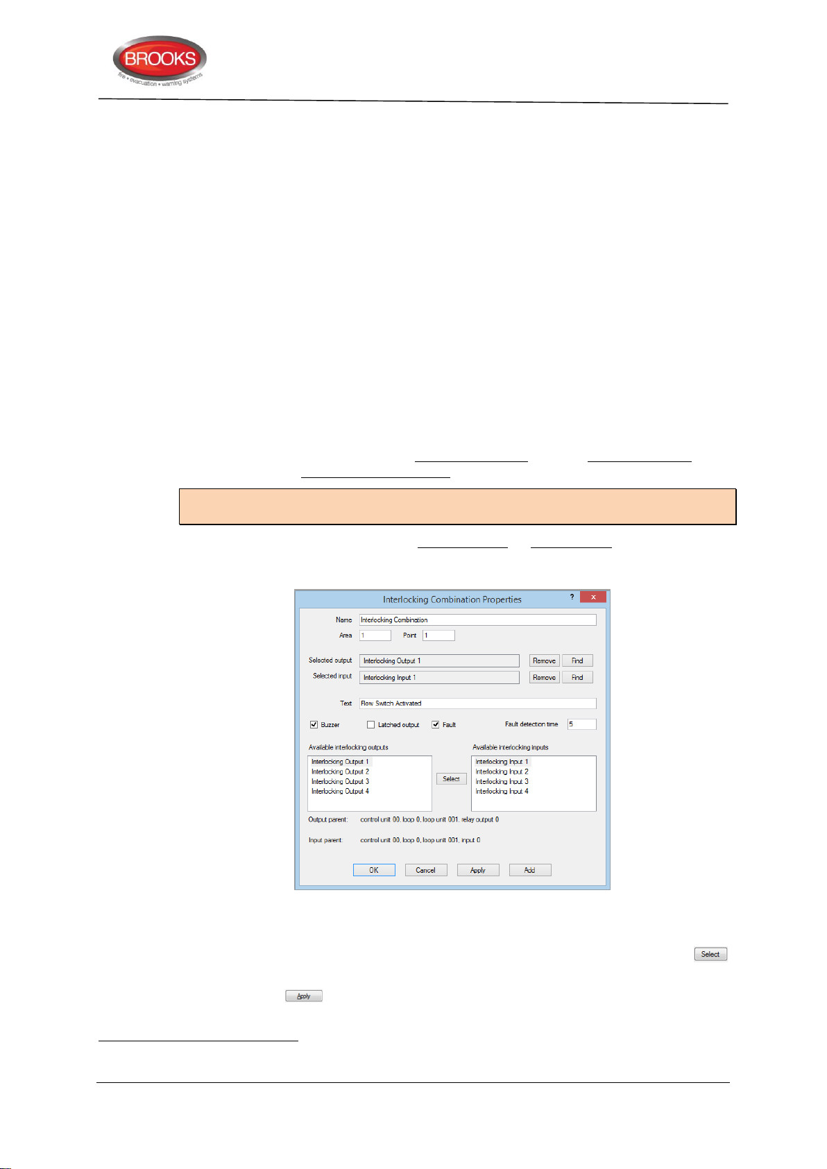
Output signal period: Steady (continuous) or Steady, delayed activation is to be
105
105
selected.
Control Expression is to be programmed for the output, i.e. for the equipment to
be controlled.
Name: It is recommended to add information, e.g. the interlocking combination's
presentation number (Area-Point).
Activated output will be indicated in menu H9/C1.
12.1.2 Interlocking Input
The "Input" dialog box is used to configure the interlocking input.
Type: "Interlocking Input" is to be selected.
Name: It is recommended to add information, e.g. the interlocking combination's
presentation number (Area-Point).
Activated input will be indicated in menu H9/C1.
12.1.3 Interlocking Combination
The interlocking function requires one interlocking output and one interlocking input to be
programmed in one interlocking combination.
Technical / Programming Manual
FT128 Rev 2.2
Note: The interlocking outputs and inputs have to be programmed first before
programming the interlocking combination.
An interlocking combination can have only an output or only an input programmed, e.g.
when a user definable text message is required to indicate an activated output or input and
alerted from the buzzer.
Figure 33 The EBLWin "Interlocking Combination" dialog box
To configure an interlocking combination, the following procedures can be used:
1 Select from each side of the interlocking inputs and/or outputs lists, click the
button, this puts the selection into the selected output/input fields.
2 Click the button, the selections will disappear from the lists and cannot be
reused elsewhere.
In the "Interlocking Combination" dialog box, all the outputs and inputs previously programmed for interlocking are listed, see
Figure 33
95
Page 96

Technical / Programming Manual
106
107
108
106
107
108
FT128 Rev 2.2
3 Click on the button beside the respective input/output to delete selections.
4 To locate the device from which each input/output has been used, click on the
adjacent button. The device dialog box will appear. This is a time saving
feature when you have close to hundred interlocks specified.
The configured interlocking combination should display the following:
Name: Displayed in the EBLWin Tree and List views. Default is "Interlocking
Combination" that can be edited when required. "Area-Point" will be added in the
tree view and shown in the list view.
Area and Point: Each “Interlocking Combination” is presented as Area-Point
(compare with Zone-Address). Area numbers 1-99 are possible to use and within
each are, Point numbers 1-99 can be used.
Available interlocking outputs list displays all the previous programmed outputs,
Type = "Interlocking".
Available interlocking inputs list displays all the previous programmed inputs,
Type "Interlocking". Select one output and one Input. Press Select and the
selected output and input will be shown in the Selected output and Selected input
field respectively.
It is possible to Remove an output / input (from the field).
It is possible to Find (open the dialog box) an output / input.
Output parent: Shows where the selected output is situated, e.g. Control unit 0.
Input parent: Shows where the selected input is situated, e.g. Control unit 0.
Text = Interlocking text to be shown in menu H9/C1. Can be written in this field or
in the "Texts" dialog box, see chapter "Creating Alarm Texts via EBLWin”, page
120.
Buzzer checked = activated interlocking input will turn on the FT128 buzzer (0.8 /
0.8 sec.)
. The buzzer can be silenced. It will be automatically turned on again,
if a new interlocking input is activated.
Latched output checked = Output reset has to be performed via menu H9/C3.
(Automatically output reset will not take place when the control expression
becomes false.).
Fault checked = Fault detection ON.
Fault Detection Time: If the input is not activated within 5-255 seconds after the
output is activated
, a fault will be generated:
FAULT: Interlocking input AA/PP
Date: MM-DD Time: HH:MM
12.2 Interlocking Indications
One or more activated Interlocking Combinations (interlocking output and/or input) are
indicated in the display in FT128
:
Interlocking input / output activated
See menu H9/C1
Disabled interlocking output is indicated by the LED "Disablements".
Priority order: Fire alarm – Pre-warning - Interlocking - Fault.
After the end of the delay time (if used).
This indication has low priority and will only be shown in the display if there are no fire alarms, faults, disablements, etc.
96
Page 97

Technical / Programming Manual
12.3 Information of Interlocking Combinations (H9)
Menu H9 has the following sub menus.
12.3.1 Activated Interlocking outputs / inputs (H9/C1)
See also chapter “Interlocking Indications”, page 96.
In menu H9/C1 information will be shown as follows:
Output AA/PP activated at HH:MM
Interlocking text.. .. ..
or
Output AA/PP act HH:MM, input act HH:MM
Interlocking text.. .. ..
or
Input AA/PP activated at HH:MM
Interlocking text.. .. ..
FT128 Rev 2.2
AA = Interlocking combination Area
PP = Interlocking combination Point within the Area
HH = Hours
MM = Minutes
Use "↑" "↓" to scroll between several interlocking combinations.
12.3.2 Activate / deactivate Interlocking Output (H9/C2)
Even if the control expression for an interlocking output is not fulfilled (true), the output can
be manually activated via this menu.
The "Interlocking Combination" (Area / Point) is to be entered to activate the output. The
corresponding interlocking input will be "monitored" in the same way as if the output was
activated by its control expression.
Reset has to be performed via menu H9/C3.
12.3.3 Reset interlocking output (H9/C3)
Activated interlocking outputs are listed here. Use "↑" "↓" to scroll between the "Interlocking
Combinations" (Area / Point).
Interlocking output activated via its control expression and latching output selected: The
output has to be reset via this menu.
Interlocking output activated via its control expression and latching output not selected: The
output can be reset via this menu.
Interlocking output activated via menu H9/C2: The output has to be reset via this menu.
12.3.4 Disable Interlocking Output (H9/C4)
Interlocking outputs (i.e. Output Type = Interlocking) can be individually disabled via menu
H9/C4. A disabled output will stay in (or return to) the normal condition for the output
respectively. The "Interlocking Combination" (i.e. Area / Point) is to be entered to disable
the output.
All the interlocking outputs can be disabled collectively via menu H2/B4.
97
Page 98

Technical / Programming Manual
12.3.5 Re-enable Interlocking Output (H9/C5)
Interlocking outputs (i.e. Output Type = Interlocking) can be re-enabled via this menu
H9/C5.
Disabled interlocking outputs are listed in menu H9/C5. Use "↑" "↓" to scroll between the
"Interlocking Combinations" (i.e. Area / Point) or type it via the key-pad.
All the interlocking outputs, disabled via menu H2/B4, can be re-enabled collectively via
menu H2/B8.
12.4 Interlocking Control Expressions
A programmable output control expression can contain "interlocking" trigger conditions
("Functions") numbers 30-33 (see Section "Control Expression”, page 84 i.e. one or more
outputs can be activated when one or more interlocking inputs are activated.
FT128 Rev 2.2
98
Page 99
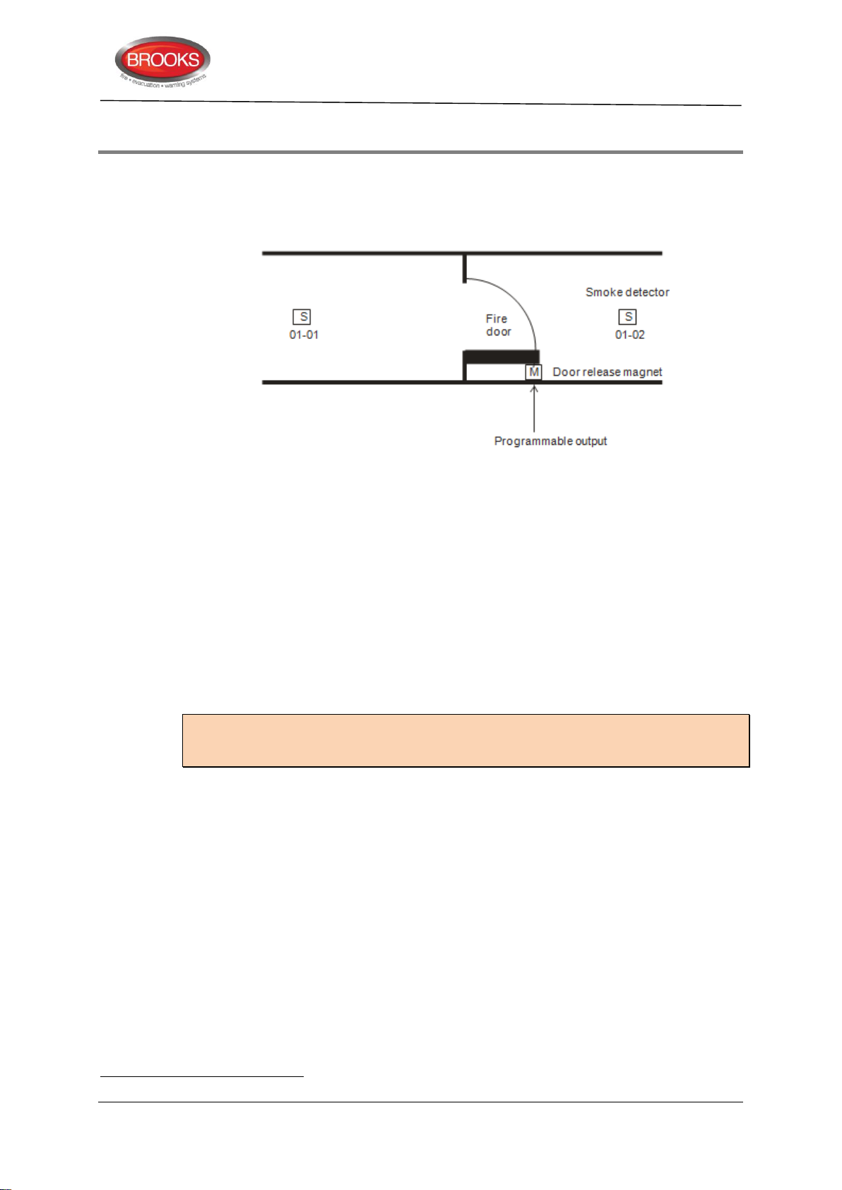
Technical / Programming Manual
109
109
13 Fire Door Closing Function
Programmable outputs can be used for fire door closing. A special trigger condition is
available (Fire Door Closing.). Type of output is normally "Control, neutral".
One or more alarm points can control the output, i.e. the detectors on both sides of the fire
door as shown in the figure below.
FT128 Rev 2.2
In case of one of the following events, the output will be "activated" and the fire door will
close:
Fire alarm (from any of the detectors controlling the fire door)
"Test mode" (the zone involved set in test mode)
Fault (i.e. "no answer" from any of the detectors
Disablement (any of the detectors controlling the fire door or the involved zone.
A definite time every day, if programmed via EBLWin. (The output will be activated
for 20 seconds.)
Via a programmable input (trigger condition trigger condition no. 9 = Door Closing
Test Input). The output will be activated for 20 seconds.
Note: For safety reasons, an I/O unit 3361 output should not be used. If a short circuit or
double break exists on the COM loop, the I/O unit cannot be forced to activate the output,
i.e. the door will not be closed.
If a magnet contact is available, it is possible to get a "closed fire door verification" via the
Interlocking function. In this case, Type of input / output has to be "Interlocking in-/output".
See also chapter Interlocking Function, page 94.
controlling the fire door)
E.g. a faulty detector, two breaks or short-circuit on the COM loop.
99
Page 100

Technical / Programming Manual
110
110
14 Functions / Services / Features
Some Functions / Services / Features require programming via EBLWin, see chapter PC
software (S/W), page 14.
How to connect the PC and more information, see chapter "Download SSD" page 157 and
"Download software (S/W)" page 160.
Notes: The information in the following sections from 14.1 - 14.7 is valid for the analogue
smoke detectors 430x / 440x in NORMAL mode.
Chapter 14.5 is valid for the analogue heat detectors 3308 / 3309 in NORMAL mode.
For the analogue detectors 440x in Advanced mode, see chapter “Advanced
Mode”, page 127.
14.1 Sensor Value
An analogue smoke detector is like a "sensor". It detects its environment at all times. Each
detected analogue value is converted in the detector to a digital "sensor values", which is
continuously picked up and evaluated by FT128 for each individual detector. In Figure 34
the (digital) sensor values (during a certain time) are represented by the graph "Working
level".
FT128 Rev 2.2
14.2 Week Average Sensor Value
Each hour, one sensor value is stored in a special memory (in FT128) and each week,
these stored sensor values are used to calculate a "week average sensor value".
is done for each analogue smoke detector individually. In Figure 34 the (digital) week
average sensor values are represented by the graph "Week average sensor value" (B).
Each analogue smoke detector has a default sensor value = 0.1 %/m and a week average
sensor value = 0.1 %/m (i.e. at Time = 0).
A "Fire Alarm Offset" (value) is added to the week average sensor value to get each
detector's "Fire Alarm Level", i.e. the fire alarm level will be adjusted in relation to each
new week average sensor value in order to keep the detector's fire alarm sensitivity
constant. The fire alarm level is in Figure 34 represented by the graph "Fire alarm level"
(C) - parallel with the graph "Week average sensor value" (B).
In Figure 34 (at Time = 0):
The week average sensor value (B) is 0.1 %/m and the fire alarm offset is 3 %/m, i.e.
the fire alarm level (C) is 0.1+3=3.1 %/m.
Service signal will be given when the week average sensor value for a detector has
reached the service signal level (1.8 %/m), i.e. the detector is "dirty" and has to be
replaced. See "Service level" (D) Figure 34. The week average sensor value will now stay
on 1.8 %/m, i.e. the detector will be more sensitive until it is replaced with a new one.
"Sensor Information" is available via menu H4/U4. Via EBLWin and a PC connected to
FT128 you can also get continuous "Sensor Information" for one or several detectors.
This
Also via the Web-server II 1598 you can get "Sensor Information" for one or several
analogue detectors on a COM loop.
The smoke detector sensor values are presented as obscuration in % per meter (%/m).
(Heat detector values as °C.)
The very first week average sensor value will be calculated within 2½ minutes after any restart, i.e. also after SSD
download. During this "2½ min. period" all analogue smoke detector fire alarms are suppressed.
100
 Loading...