

Page 1
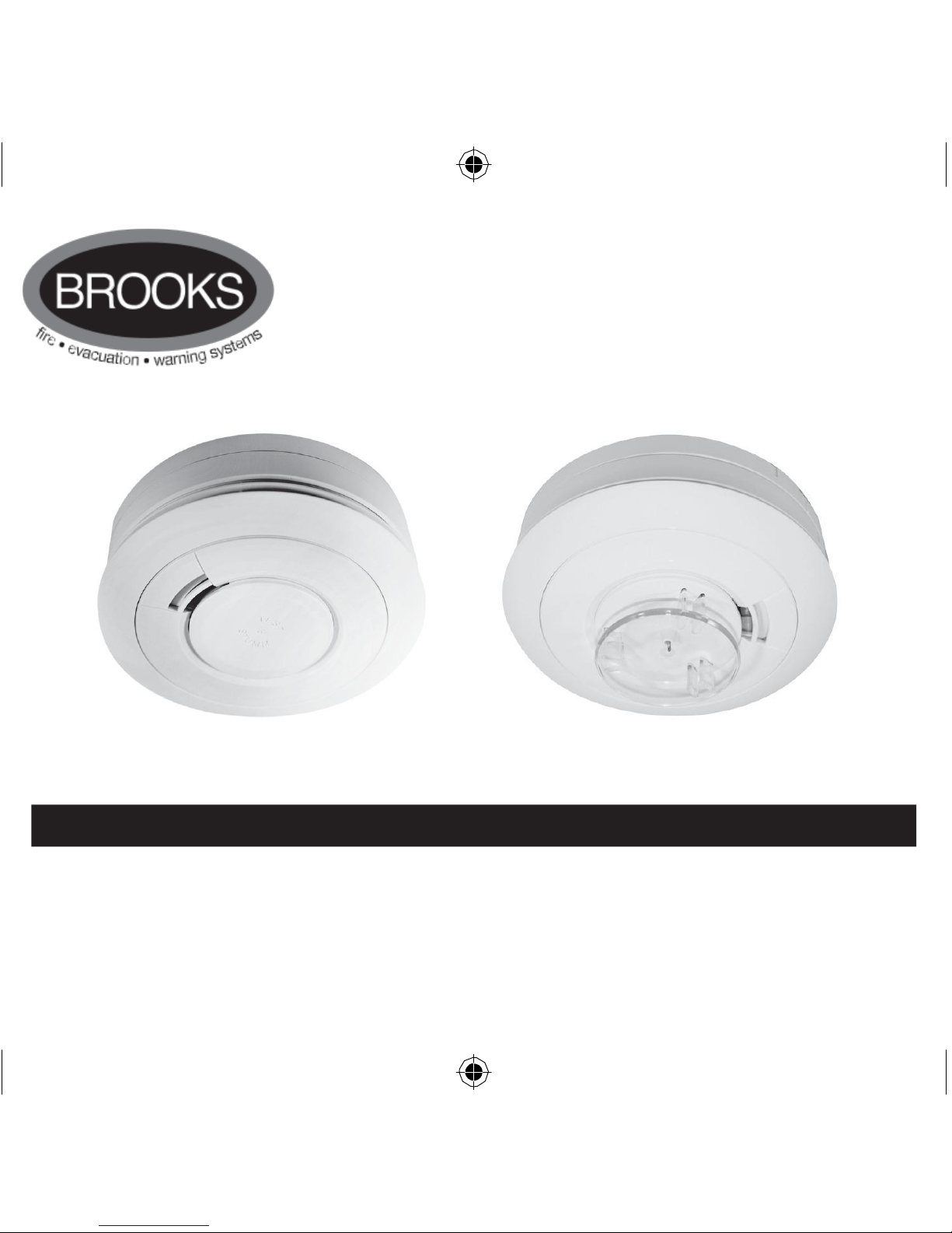
Battery
Powered
Smoke & Heat
Alarms
EIB600
Series
EIB605 Smoke Alarm Series EIB603 Heat Alarm
Series
Instructions
Read and retain carefully for as long as the product is being
used
. It contains vital information on the operation and installation
of your
Alarm.
The leaflet should be regarded as part of the product.
If you are just installing the unit, the leaflet must be given to the
householder.
The leaflet is to be given to any subsequent user.
Page 2
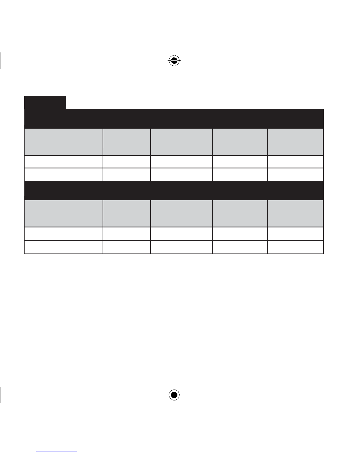
Table 1
9V Replaceable
Battery
Model
Alarm
Type
Hardwired
Inter
connect
RF
Capability
Supplied
Optional
RF Module
Model No.
EIB605C
Optical
Yes
Yes
EIB605MRF
EIB603C
Heat
Yes Yes
EIB605MRF
10
Year Lithium Battery
Built-in
Model
Alarm
Type
Hardwired
Inter
connect
RF
Capability
Supplied
Optional
RF Module
Model No.
EIB605TYC
Optical
Yes Yes
EIB605MTYRF
EIB603TYC
Heat
Yes Yes
EIB605MTYRF
Note: Certain alarms may be supplied (on request) with the appropriate RF module
fitted
Page 3

CONTENTS
Page
1 QUICK START GUIDE 4
2 LOCATION & POSITIONING 6
3 INSTALLATION 13
4 INTERCONNECTION - HARD WIRED 17
5 TESTING, MAINTENANCE & POWER SUPPLY 20
MONITORING
6 FIRE SAFETY ADVICE 26
7 SMOKE ALARM LIMITATIONS 29
8 RADIOLINK ACCESSORIES 31
9 GETTING YOUR ALARM SERVICED 31
10 FIVE YEAR GUARANTEE 32
11 TROUBLESHOOTING 33
12 CONTACT US 36
3
Page 4
ALARM
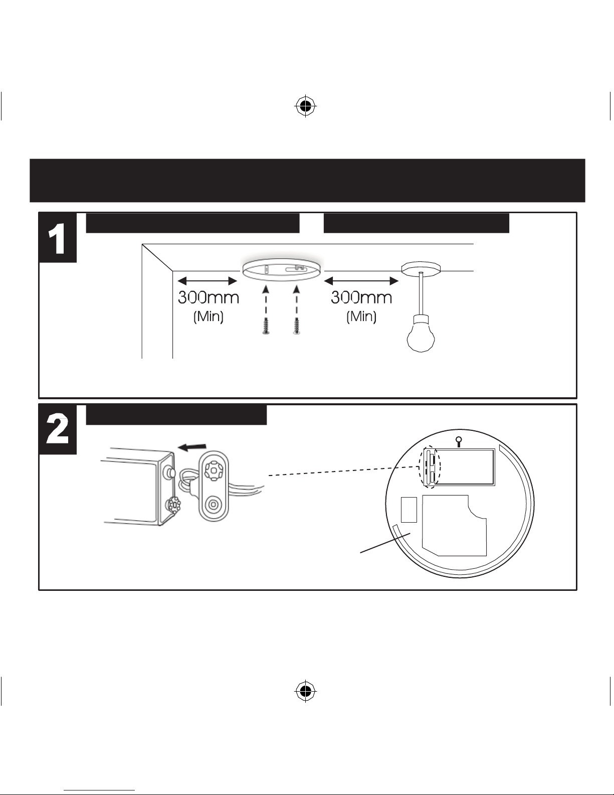
1. Quick Start
Guide
LOCATE CORRECT SITING POINT FIX BASEPLATE TO
CEILIN
G
ALARM SHOULD
BE
CEILING MOUNTED
AT
LEAST
300MM FROM
WALLS &
OBSTRUCTIONS, IDEALLY CENTRALLY
IN ROOM/AREA
CONNECT BATTERY SNAPS 9V
REPLACEABLE
BATTERY MODELS
ONLY
9 VO LT
BATTERY
BATTERY
CONNECTORS
CONNECT
THE
BATTERY
TO THE
BATTERY SNAPS
TO
POWER
THE UNIT
BASE OF
ALARM
4
ON 10 YEAR LITHIUM BATTERY
07/12/2010 11:11
Page 5
Quick Start
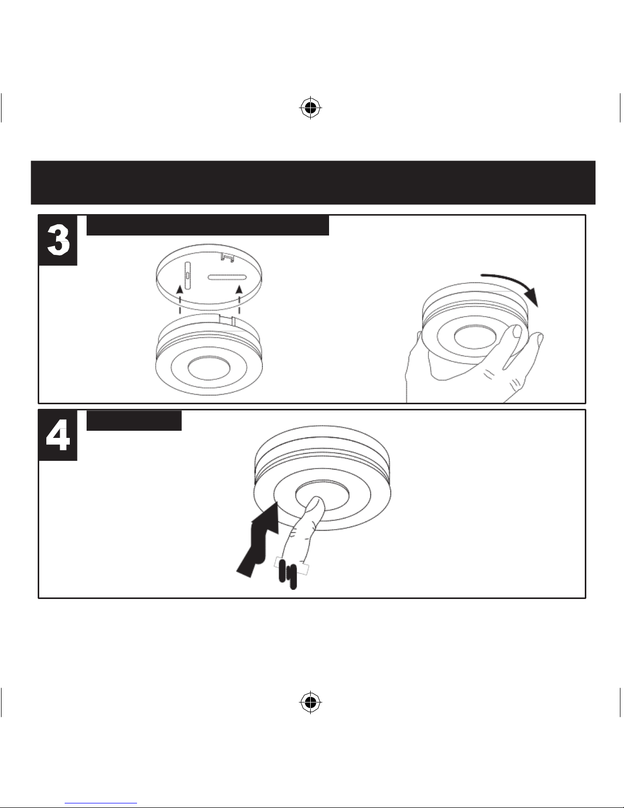
Guide
PLACE ALARM & TWIST ON TO BASE
ON 10 YEAR LITHIUM BATTERY
ALARM
MODELS - TWISTING THE UNIT ON
TO
THE BASE
AUTOMATICALLY CONNECTS
THE
BATTERY
TEST
ALARM
PRESS
THE TEST BUTTON
TEST
ALARM AT LEAST
WEEK LY
5
Page 6

Introduction
2. Location & Positioning
Congratulations on purchasing an EIB600 Series Alarm. You can easily install
the smoke alarms throughout the property on escape routes, on each storey, in
corridors & in closed rooms to give warning of fire.
The Heat Alarms can be installed in kitchens and other areas where Smoke Alarms
are unsuitable.
All the models can be interconnected with hard wiring to give the loudest alarm
sound level throughout the house.
All models can alternatively be interconnected using the RadioLINK plug-in modules
(These modules must be purchased separately when they are not supplied with the
Alarm (see Table 1)).
Note: Certain alarms may be supplied (on request) with the appropriate RF module
fitted.
SMOKE ALARMS - EIB605 Series
Sufficient smoke must enter your Smoke Alarm before it will respond. Your Smoke
Alarm needs to be within 7.5 metres of the fire to respond quickly. Smoke Alarms
also need to be in positions where they can be heard throughout the property, so
they can wake you and your family in time for everyone to escape. A single Smoke
Alarm will give some protection if it is properly installed, but most homes will require
two or more (preferably interconnected) to ensure that a reliable early warning is
given. For recommended protection you should put individual Smoke Alarms in
all rooms (apart from kitchen and bathroom) where fire is most likely to break out.
6
Page 7

Location & Positioning
Your first Smoke Alarm should be located between the sleeping area and the
most likely sources of fire (living room, kitchen for example), but it should not
be more than 7.5 metres from the door to any room where a fire may start and
block your escape from the house.
HEAT ALARMS - EIB603 Series
The Heat Alarm gives a fire warning when the temperature at the Alarm
reaches 62°C. It is ideal for kitchens, garages, boiler houses and other areas
where there are normally high levels of fumes, smoke or dust i.e. places where
Smoke Alarms cannot be installed without the risk of excessive nuisance
alarms. A Heat Alarm should only be used in rooms adjoining escape routes,
in conjunction with Smoke Alarms on the escape routes.
All Heat Alarms must be interconnected to the Smoke Alarms to ensure that
the early warning will be heard, particularly by somebody sleeping. A properly
designed early warning fire system ensures the alarm is given before the
escape routes become blocked with smoke. Therefore there must be Smoke
Alarms along the escape routes as Heat Alarms would not give sufficient
warning.
However, a fire in a closed room (e.g. kitchen) adjoining the escape route, can
eventually cause the corridor to become smoke-logged due to smoke leaking
out from around the door before adequate warning can be given by detectors in
the corridor. (Smoke leaking out from a room is often cool and slow moving so it
can take a long time to rise to the ceiling, and travel to a detector which could be
some distance away). A Heat Alarm in the closed room will give early warning
of fire in that room and help overcome this problem.
7
Page 8

Multi-Storey Dwellings
If your home has more than one floor, at least on e Alarm should be fitted on each level
(see Figure 1). Preferably the units should be interconnected so as to give sufficient
warning throughout the property. RadioLINK plug-in modules are ideal in this situation
as the units will then interconnect using Radio Frequency (RF) signals - so no wiring
is required. Alternatively the alarms can be interconnected by hard wiring.
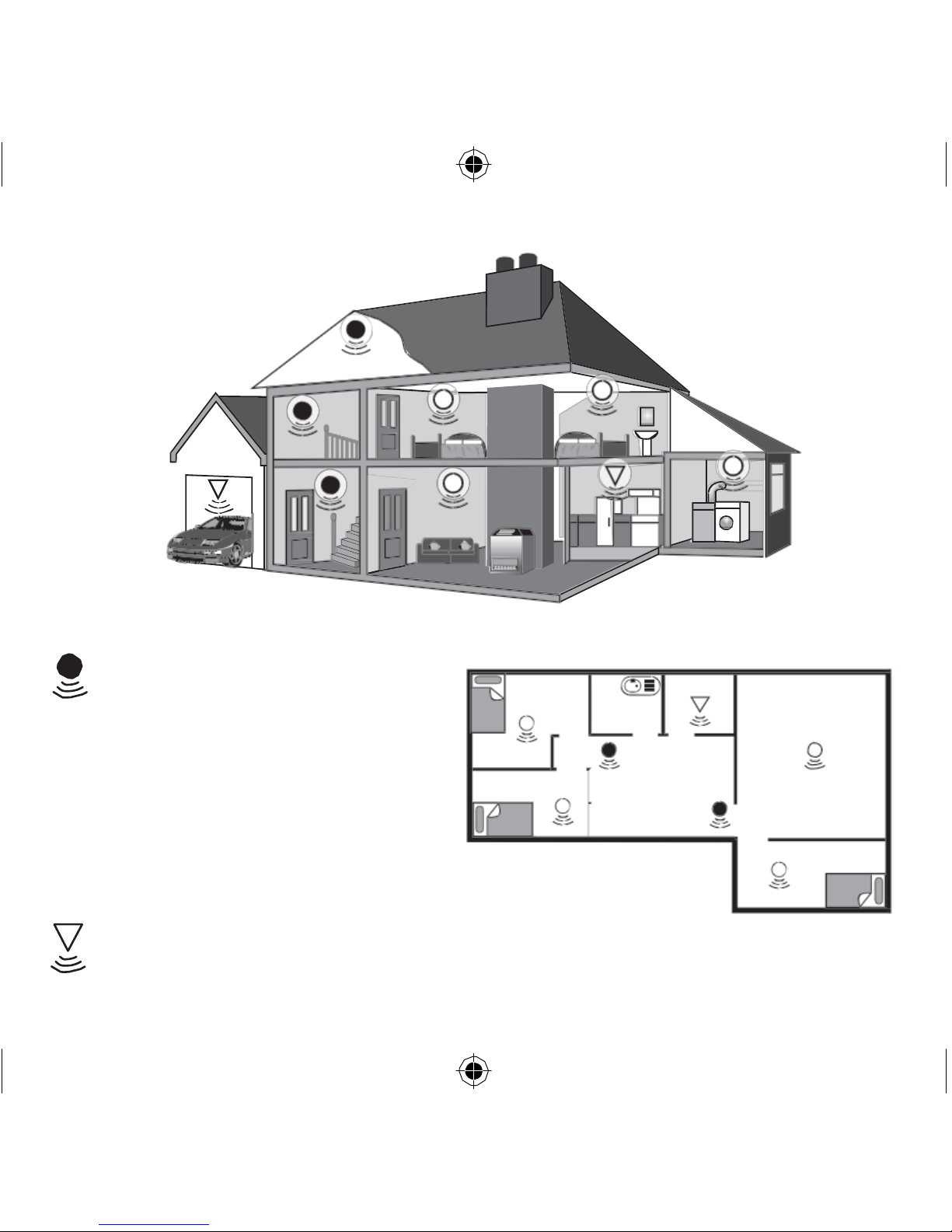
Figure 1 illustrates where Heat Alarms and Smoke Alarms should be located in a
typical two storey house. Note the spacings in “Protection Levels” which ensure the
early detection of fire and that the warning will be heard.
Locate Heat Alarms in rooms adjoining escape routes - kitchens, garages, boiler
houses etc. where Smoke Alarms are unsuitable. Install within 5.3m of potential
sources of fire.
Single Storey Dwelling
If the premises is one storey you should put your first Smoke Alarm in a corridor or
hallway between the sleeping and living areas. Place it as near to the living area as
possible, but make sure that it can be heard loudly enough in the bedroom to wake
someone. See Figure 2 for placement example.
In houses with more than one sleeping area, Smoke Alarms should be placed
between each sleeping area and the living area and it is recommended that Heat
Alarms should be placed in the kitchen & garage.
Recommended Protection
Fire authorities recommend you put individual Smoke Alarms in or near all rooms
where fire is most likely to break out (apart from the locations to avoid e.g bathrooms
- see Section 3). The living room is the most likely place for a fire to start at night,
8
Page 9
f
o l l o w e d by the
k i t c h e n ( w h e r e
a Heat Alarm is
Figure 1
For minimum protection
- Smoke Alarm on each storey
- in each sleeping area
- every 7.5 metres of hallways and
rooms
- within 3 metres of all bedroom doors
Bedroom
Ba
thr
oom
Kitchen
Living
Room
- all units interconnected
Bedroom
Dining
Room
For recommended
protection
(in addition to the above):
- Smoke Alarms in every room (except
kitchens and bathrooms)
- Heat Alarms located in kitchens,
garages etc. within 5.3m of potential
fire sources
9
Figure 2
Bedroom
Page 10

recommended) and then the dining room. Consideration should be given to
installing Smoke Alarms in any bedrooms where fires might occur, for instance,
where there is an electrical appliance such as an electric blanket or heater, or
where the occupant is a smoker. In addition, consideration should be also given
to installing Smoke Alarms in any rooms where the occupant is unable to respond
very well to a fire starting in that room, such as an elderly or sick person or a very
young child.
Checking Alarms Can Be Heard
With the Alarms sounding in their intended locations check that the alarm can be
heard in each bedroom with the door closed, above the sound of any TV/audio
systems. The TV/audio systems should be set to a reasonably loud conversation
level. If you cannot hear the alarm over the sound of the TV/audio system, the
chances are it would not wake you. Interconnecting the Alarms using either a
hard-wired interconnection (where the feature is present) or RadioLINK plug-in
modules will help to ensure that the alarm will be heard throughout the property.
Positioning
Ceiling Mounting
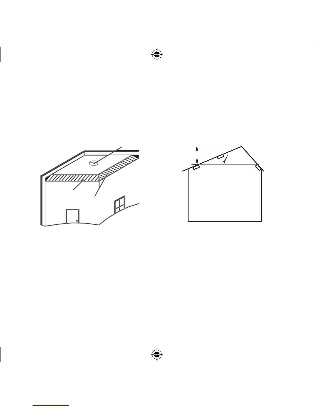
Hot smoke rises and spreads out, so a central ceiling position is the recommended
location. The air is “dead” and does not move in corners, therefore Smoke & Heat
Alarms must be mounted away from corners. Keep at least 0.3m from walls and
corners (see Figure 3). Additionally, mount the unit at least 0.3m from any light
fitting or decorative object which might prevent smoke or heat entering the Smoke/
Heat Alarm.
We do not recommend wall mounting these Smoke/Heat Alarms.
10
Page 11
On a Sloping Ceiling
With a sloping or peaked ceiling install a Smoke Alarm within 600mm of the peak or
a Heat Alarm within 150mm of the peak (measured vertically). If this height is less
than 600mm for Smoke Alarms or 150mm for Heat Alarms the ceiling is regarded
as being flat (see Figure 4).
IDEAL IN CENTRE
OF CEILING
SMOKE
ALARMS
<600mm
HEAT
ALARMS
<150mm
APEX
x x
DEAD AIR SURFACES
NEVER WITHIN 0.3M
OF ANY CORNER
Figure 3
Figure 4
Locations to avoid
DON’T place Smoke Alarms in any of the following areas:
•
Bathrooms, kitchens, shower rooms, garages
or other rooms where the
smoke
alarm may be triggered by steam, condensation, normal smoke or fumes. Keep
at least 6 metres away from sources of normal smoke/fumes.
• Locate away from
very
dusty
or di
rty areas as dust build-up in
the
chamber
can impair
performance. It can also block the insect screen mesh and prevent smoke from
entering th e smoke detector chamber.
11
Page 12

• Do not locate in insect
infested areas.
Small
insects
getting into the
smoke
detector chamber can cause intermittent alarms.
DON’T place Heat Alarms in any of the following areas:
•
Bathrooms, shower
rooms or other rooms where the unit may be
triggered by
steam or condensation.
DON’T place Smoke or Heat Alarms in any of the following areas:
•
Places
where the normal
temperature
can
exceed
45°C or be below 5°C
(e.g.
attics, furnace rooms, directly above ovens or kettles etc.) as the heat/steam
could cause nuisance alarms.
• Near a
decorative
object, door, light fitting, window moulding etc., that
may
prevent smoke or heat from entering the Alarm.
• Surfaces
that are normally warmer or colder than the
rest
of
the room (e.g. attic
hatches). Temperature differences might stop smoke or heat from reaching the unit.
• Next to or directly
above heaters
or air conditioning
vents,
windows, wall vents
etc.
that can change the direction of airflow.
• In very high or awkward
areas
(e.g. over stairwells) where it may be difficult to
reach the alarm (for testing, hushing or battery replacement).
• Locate the unit at least 1m from dimmer controlled lights and wiring
as some
dimmers can cause interference.
• Locate unit at least 1.5m and route wiring at least 1m away from
fluorescent
light
fittings as electrical “noise” and/or flickering may affect the unit.
12
Page 13
Installation
Installation Procedure
3. Installation
1. Select a location complying with the advice in Section 2.
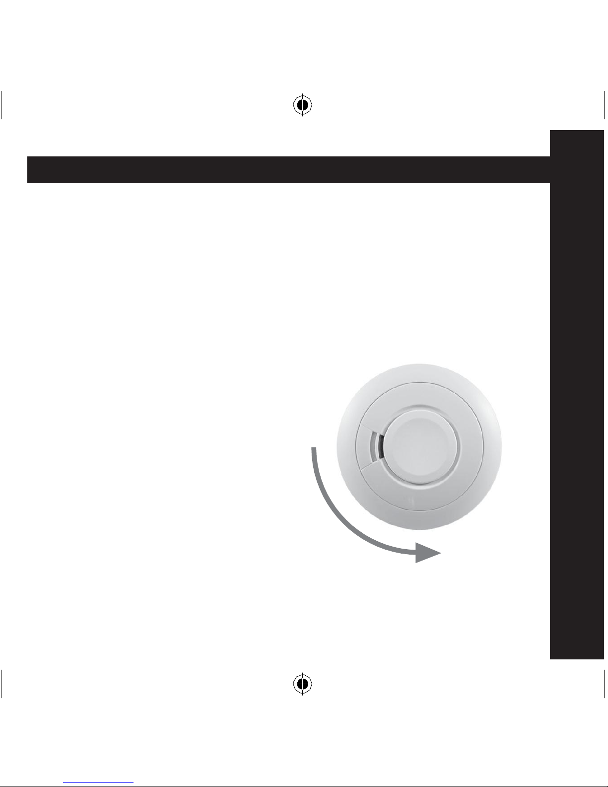
2. Remove the mounting plate from the Smoke/Heat Alarm by twisting it in an
anti-clockwise direction (see Figure 5).
3. Place the mounting plate on the ceiling exactly where you want to mount the
Alarm. With a pencil, mark the location of the two screw holes.
4. If interconnecting Alarms using
hard-wired connections, run suitable
twin core cabling to the marked locations
of each Alarm. Make the connections to
the Alarm (see Section 4).
5. Taking care to avoid any electrical
wiring in the ceiling, drill holes using
a 5.0mm drill bit through the centre of
the marked locations. Push the plastic
screw anchors provided into the drilled
holes. Screw the mounting plate to the
ceiling.
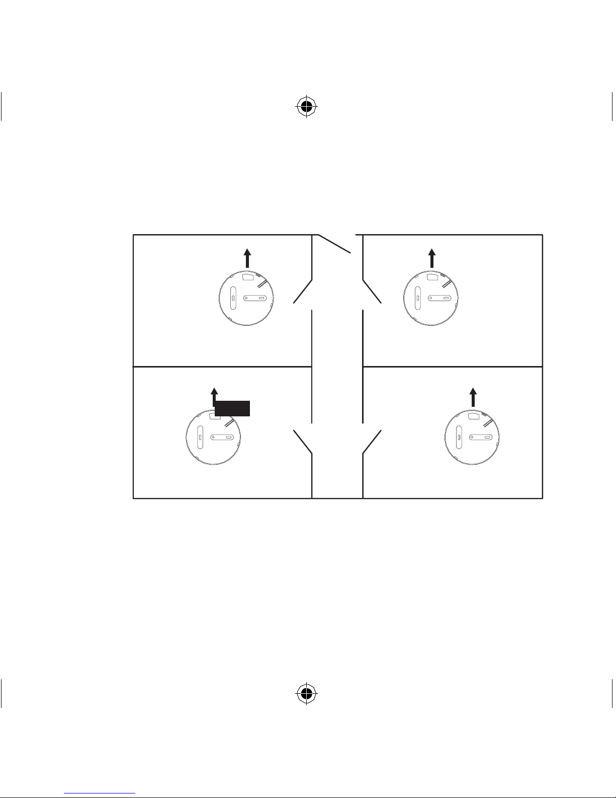
If using RadioLINK Smoke/Heat Alarms
then they should be mounted with
antennas in the same orientation (i.e.
essentially parallel). This means picking
13
ROTA TE UNIT
ANIT-CLOCKWISE
UNIT WILL NOT TWIST OFF - IT MAY
BE
TAMPERPROOFED
- SEE
FIGURE 8c
Figure 5
Page 14
6 .
a part of the building, say the front wall of the building and then installing all
mounting plates in the same orientation with respect to this (see figure 6).
Front Wall Front
Wall
Orientate
all
mounting
plates
in the
same
direction
Figure 6
Mounting Plate Mounting Plate
Large
hole
nearest
front
wall
Mounting Plate Mounting Plate
Connect the battery to the battery snaps as shown in the Quick Start Guide (for
9V Replaceable Battery models only).
7. Carefully line up the unit on the base, gentle press home & twist on. (This
connects the batteries in the 10 Year Lithium Battery models).
Install all the other Alarms similarly.
14
Page 15
nection, see booklet „R
F Modules for Battery
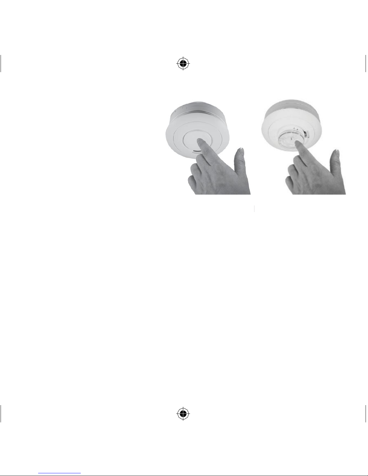
8. Press the Test button on each
alarm to ensure that the Alarm
works (see Figure 7a for Smoke
Alarm & 7b for Heat Alarm).
9. For hard-wired interconnected
Alarms, hold down the Test button
on each Alarm in turn and check
that all other interconnected Alarms
sound.
10. If using RadioLINK intercon
Powered Smoke & Heat Alarms.
Install all the other Alarms similarly.
Tamperproofing the Alarms
Smoke Alarm
Figure 7a
Heat Alarm
Figure 7b
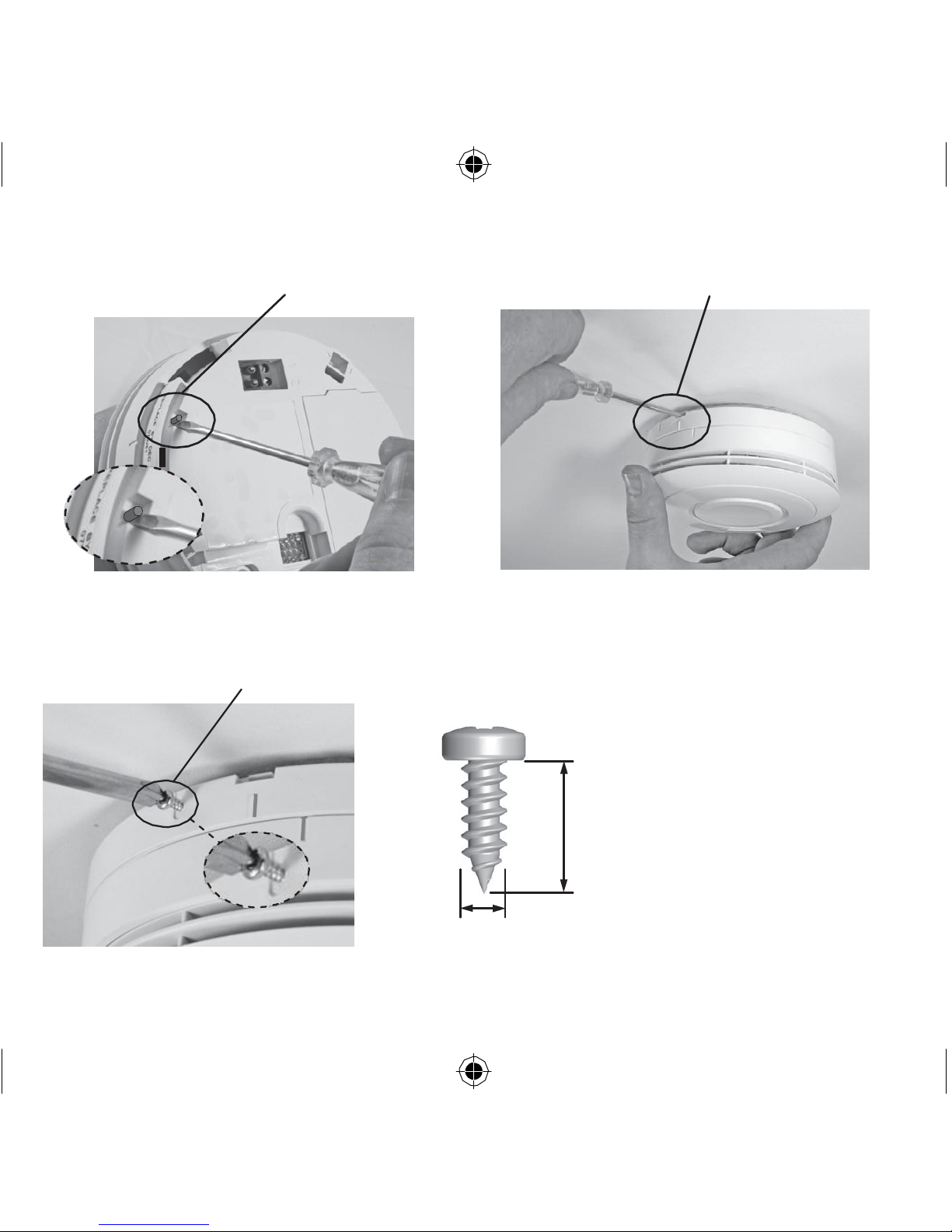
The Alarm can be made tamperproof to prevent unauthorised removal of the Alarm.
Break off the small pillar on the base as shown in figure 8a.
To remove the Alarm from the ceiling it is now necessary to use a small screwdriver,
to release the catch (push catch towards the ceiling) and then twist off the alarm
(see figure 8b).
If necessary it is possible to further secure the Alarm by using a No.2 or No.4 (2 to
3mm diameter - not supplied) self tapping screw 6 to 8mm long (see figure 8d), to
firmly lock the Alarm and its mounting plate together (see figure 8c).
Attach the Alarm to the mounting plate.
15
Page 16
6 to 8 mm
BREAK
OFF
SMALL
PILLAR
PUSH UP CATCH &
TWIST
ALARM ANTI-CLOCKWISE
TO
REMOVE
How to Tamperproof
Figure 8a
How to Remove
Figure 8b
TAMPERPROOF SCREW
Figure 8c
SELF TAPPING
SCREW
2 to 3 mm
Figure 8d
16
Line up the screw (not
supplied) on the “U”
shaped recessed area
shown in figure 8c and
screw firmly home.
To remove the Alarm from
the ceiling, remove the
screw first, and then twist
off anti-clockwise.
Page 17
Interconnection - Hard Wired
4. Interconnection - Hard
Wired
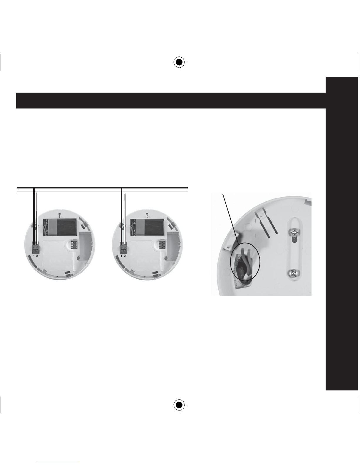
A combined maximum of 12 Smoke Alarms and/or Heat Alarms may be wired
together such that when one unit senses fire all other units sound a warning.
This helps ensure the alarm will be heard throughout the property.
Do not
connect
to any other device
as
it may
damage
the unit or
affect
performance.
OPENING IN
MOUNTING PLATE
Figure 9a
Figure 9b
A maximum of 250 metres of two core, 0.5mm2 to 0.75mm2, stranded signal
cable can be used, (maximum resistance between detectors 50 ohm). The
Alarms are interconnected by wiring all the terminals marked 1 together, and
all the terminals
marked 2 together (see
in Figure 9a). Note:
Draughts from
wiring openings, conduit, or mounting boxes/holes, may blow smoke away
17
Page 18
from the sensing chamber, making it insensitive. It is essential that all such ceiling
openings be closed with silicone sealant or similar.
1. Run the two core cable to the Alarm locations.
2. Bring the cable through the opening in the mounting plate (before screwing it to
the ceiling) see figure 9b.
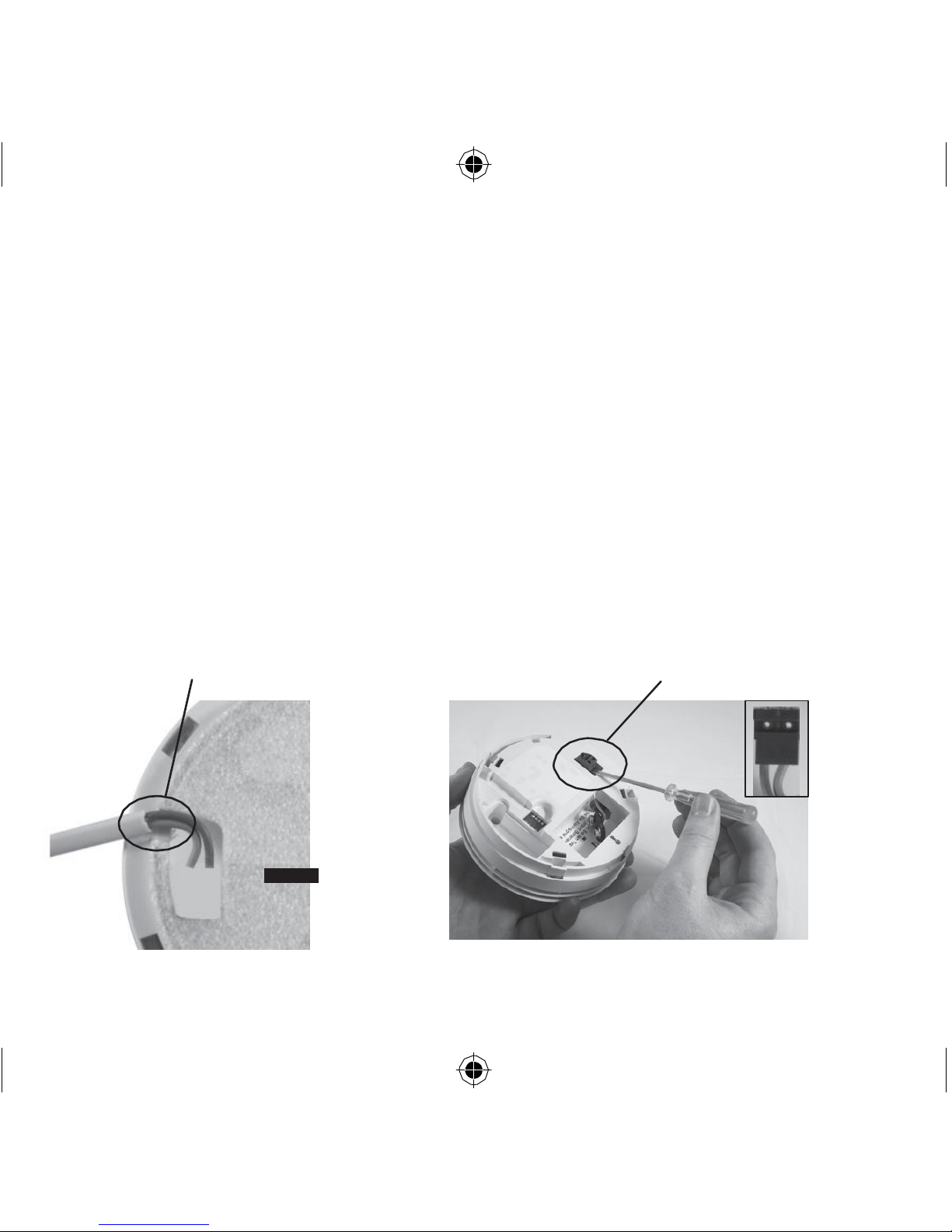
3. If you are bringing the wiring along the surface, break out the two notches (see
figure 10a).
4. Using a small screwdriver, lift off the terminal block by raising it vertically (see
figure 10b).
5. Screw the two cable cores into the terminal block (see figure 10b). Then carefully
press the terminal block back on to the two pins in the base.
6. Twist the Alarm clockwise on to the mounting plate.
BREAK
OUT
SIDE
WALLS
USE SCREWDRIVER TO GENTLY
LIFT OUT THE TERMINAL BLOCK
SCREW
CABLES
INTO
TERMINAL
BLOCK
REAR
OF
MOUNTING
PLATE
Figure 10a
Figure 10b
18
Page 19

Testing, Maintenance & Power Supply Monitoring
Install and connect all the other Alarms similarly.
Now test the first Alarm by pressing and holding the Test button (this may take
up to 5 seconds). The red indicator light will flash about once a second on
the first Alarm and all other Alarms should sound. Check all the other Alarms
similarly.
Note: These Alarms should be interconnected only within the confines of a
single family living unit. If they are connected between different residences
there may be excessive nuisance alarms. Everybody may not be aware that
they are being tested or that it is a nuisance alarm caused by cooking etc.
5. Testing, Maintenance & Power Supply Monitoring
Your Alarm is a life saving device and should be checked periodically.
Regularly check that the red light on the Alarm flashes approx once a minute
to show the units are powered. Replace the Alarm if the flashing stops.
5.1 Manually Testing your Alarms
It is recommended that you test your Alarms after installation and then at least
weekly to ensure the units are working. It will also help you and your family to
become familiar with the sound of the Alarms.
- Press and hold the Test Button until the Alarm sounds and the red light
flashes (see Figure 7a & 7b). The Alarm will stop sounding shortly after the
button is released.
- If the Alarms are interconnected using hard-wired connections, check that all
interconnected Alarms sound.
19
Page 20

- If they ar e interconnected using RadioLINK modules, hold down the Test button until
the blue light on the cover of th e Alarm illuminates. Check that all other Alarms sound.
- Release the Test button. The Alarm and all connected Alarms should stop
sounding.
- Repeat this procedure for all other Alarms in the system.
WARNING: Do not test with flame.
This can set fire to the Alarm and damage the house. We do not recommend testing
with smoke or heat as the results can be misleading unless special apparatus is used.
When you press the Test button it simulates the effect of smoke in a Smoke Alarm
and heat in a Heat Alarm which they could experience in a real fire. So, there is no
need to test either Alarms with smoke or heat.
5.2 Test/Hush Button to Control Nuisance Alarms
The Smoke Alarms have a combined Test/Hush button to help you control
nuisance/false alarms.
If, when the Alarm sounds, there is no sign of smoke or noise to indicate that there
is a fire, it should be assumed that it is due to an actual fire and the dwelling should
be evacuated immediately.
Check the house carefully in case there is a small fire smouldering somewhere.
Check whether there is some source of smoke or fumes, for example cooking
fumes being drawn past the Alarm by an extractor.
If there are frequent nuisance/false alarms it may be necessary to re-locate the
Smoke Alarm away from the source of the fumes.
20
Page 21

If you installed Alarms with RadioLINK modules and did not House Code them,
you may be receiving alarm signals from a neighbouring system. This can be easy
rectified by “House Coding” your Alarms - see booklet „RF Modules for Battery
Powered Smoke & Heat Alarms.
1. To cancel a false alarm from a Smoke Alarm (which has its red light flashing
rapidly), press the Test/Hush button (the Smoke Alarm will automatically switch to
a reduced sensitivity condition).
The Smoke Alarms will be silenced for a period of approximately 10 minutes. The
red light on the cover of the Smoke Alarm will flash every 10 seconds (instead of
40 seconds) to indicate that the unit has been silenced.
2. The Smoke Alarm will reset to normal sensitivity at the end of the silenced period
(10 minutes). If additional silenced time is required, simply push the Test/Hush
button again.
3. If kitchen usage/layout is such that there are an unacceptable level of nuisance
alarms, re-locate the Smoke Alarm further away where it will be less affected by
cooking fumes etc. We recommend the use of a Heat Alarm in the Kitchen area to
avoid such nuisance alarms.
5.3 Power Supply Monitoring
5.3.1 What to do when an Alarm is beeping:
1. A Smoke Alarm is beeping about once a minute with the red light flashing at the
same time:
- If it is a 9V Replaceable Battery model then replace the battery.
- If it is a 10 Year Lithium Battery model then replace the entire unit.
21
Page 22

2. A Heat Alarm is beeping about once a minute.
- If it is a 9V Replaceable Battery model then replace the battery.
- If it is a 10 Year Lithium Battery model then replace the entire unit.
3. On 10 Year Lithium Battery models with RadioLINK modules (fitted) - If the blue
light flashes every 10 seconds it indicates that the RF battery is depleted and the
RadioLINK module must be replaced.
5.3.2 Battery Replacement - (9V Replaceable Battery models only)
A fresh Alkaline Battery should last for over a year. When the battery power is low
and replacement is necessary, the Smoke Alarm will “beep” and the red light will
flash at the same time about once per minute for at least 30 days. The Heat Alarm
will also beep once per minute, but the red light will not flash at the same time when
the battery is low. The battery must then be replaced. Also, replace the battery if the
Alarm does not sound when the Test Button is pressed. For maximum reliability,
replace the battery at least once a year. When you replace the battery you must
press the Test button to check that the Alarm is functioning correctly. Only replace
the battery with one of the following alkaline
batteries:
Duracell MN1604,
Energizer
6LR61, Philips 6LR61, Varta 6LR61 or the Ultralife U9VL-J lithium battery. The
lithium battery willl last longer than an alkaline battery.
All Models: Prolonged exposure to low or high temperatures or high humidity may
reduce battery life. Prolonged periods of alarm will also reduce battery life.
5.3.3 RadioLINK Module Units
If all the RadioLINK Alarms sound for 2 seconds every 4 hours, it means at least
one of the Alarms in the system has a depleted battery. Locate the depleted
battery(ies) as above.
22
Page 23

5.4 Cleaning your Alarm
Clean your Alarm regularly. Use a soft bristle brush or the brush attachment of your
vacuum cleaner to remove dust and cobwebs from the side slots where the smoke/
heat enters. To clean the cover, wipe with a damp cloth and dry thoroughly.
WARNING: Do not paint your Alarm.
Other than the maintenance and cleaning described in this leaflet, no other
customer servicing of this product is required. Repairs, when needed, must be
performed by the manufacturer.
5.5 Smoke Alarm Automatic Self-Test
The smoke chamber in the Smoke Alarms automatically tests itself about once a
minute. If the chamber is degraded it will beep without the red light flashing at the
same time. If this happens clean the unit. If the beeping persists and the beep does
not coincide with a red light flash, return the unit for service (see Section 9 - Getting
your Smoke Alarm Serviced).
5.6 Dust & Insect Contamination
All Smoke Alarms and particularly the optical (photoelectric) type are prone to
dust and insect ingress which can cause false alarms. (Heat Alarms are not as
susceptible to dust and contamination as Smoke Alarms, but it is prudent to clean
them periodically).
The latest design, materials and manufacturing techniques have been used in the
construction of Brooks Alarms to minimise the effects of contamination. However
it is impossible to completely eliminate the effect of dust and insect contamination,
and therefore, to prolong the life of the Alarm you must ensure that it is kept clean
so that excess dust does not build up. Any insects or cobwebs in the vicinity of the
Smoke Alarm should be promptly removed.
23
Page 24

In certain circumstances even with regular cleaning, contamination can build up in
the smoke sensing chamber causing the alarm to sound. If this happens the Smoke
Alarm must be returned for servicing or replacement. Contamination is beyond our
control, it is totally unpredictable and is considered normal wear and tear. For this
reason, contamination is not covered by the guarantee and a charge is made for
all such servicing work.
5.7 End of life
The entire Alarm must be replaced if:(i) All Models:
• The unit is installed for over 10
years
(check the “replace by” date
marked
on
the
side of the unit).
(ii) All 10 Year Lithium Battery models only
• The
Smoke
Alarm is giving a short
beep
about once a minute and the red light
flashes at the same time for longer than 1 hour. The Heat Alarm is giving a short
beep about once a minute for longer than 1 hour.
• The Alarm fails to
sound
the horn loudly when the test button is
pressed.
Before the Alarm is safely discarded, remove from the mounting plate. With the 9V
Replaceable Battery models disconnect the battery.
Do not put the Alarm into a fire.
The Alarm should be disposed in a safe and environmentally sound manner at your
local recycle centre. Contact your local authority for further advise.
24
Page 25

Fire Safety Advice
6. Fire Safety Advice
When using household protective devices, basic safety precautions should
always be followed, including those listed below
•
Please
read all
instructions.
•
Rehearse emergency escape
plans so
everyone
at home knows what to do
in case the alarm sounds.
• Use the Alarm Test Button to familiarise your family with the Alarm
sound and
to
practice
fire
drills regularly with all family
members.
Draw up a floor plan
that
will show each member at least 2 escape routes from each room in the house.
Children tend to hide when they don‟t know what to do. Teach children how
to escape, open windows, and use roll up fire ladders and stools without adult
help. Make sure they know what to do if the alarm goes off.
•
Constant exposure
to high or freezing
temperatures,
high humidity or a
high
level of nuisance alarms may reduce the life of the battery.
•
Nuisance alarms
can be quickly
silenced
by fanning vigorously with a
newspaper or similar to remove the smoke or press the test / hush button.
• Do not
attempt
to
remove, recharge
or burn the
battery, as
it may
explode.
•
If
it is
necessary
to
remove
the battery for
separate disposal, handle
carefully to avoid possible eye damage or skin irritation if battery has leaked
or corroded.
• To maintain sensitivity to
smoke/heat,
do not paint or cover the Alarm in
any
manner; do not permit any accumulation of cobwebs, dust or grease.
25
Page 26

•
If
Alarm has
been damaged
in any way or
does
not function properly, do
not
attempt a repair. Return the Alarm (see Section 9).
• This
appliance
is
intended
ONLY for
premises
having a
residential type
environment.
• This is not a
portable
product. It must be
mounted
following the
instructions
in
this
instruction leaflet.
•
Smoke/Heat Alarms
are not a substitute
for insurance.
The supplie
r or
manufacturer is not your insurer.
Fire Safety Hints
Store petrol and other flammable materials in proper containers.
Discard oily or flammable
rags.
Always use a metal fireplace screen and have chimneys cleaned regularly.
Replace worn or damaged sockets, switches, home wiring and cracked or frayed
electrical cords and plugs.
Do not
overload
electrical
circuits.
Keep matches away from children.
Never smoke in bed. In rooms where you do smoke, always check under cushions
for smouldering cigarettes and ashes.
Service central heating systems regularly.
Be sure all electrical appliances and tools have a recognised approval label.
26
Page 27
This device cannot protect all persons at all times. It may not protect against the
three most common causes of fatal fires:
1. Smoking in bed.
2. Leaving children at home alone.
3. Cleaning with flammable liquids, such as petrol.
Further information can be obtained from the Fire Brigade.
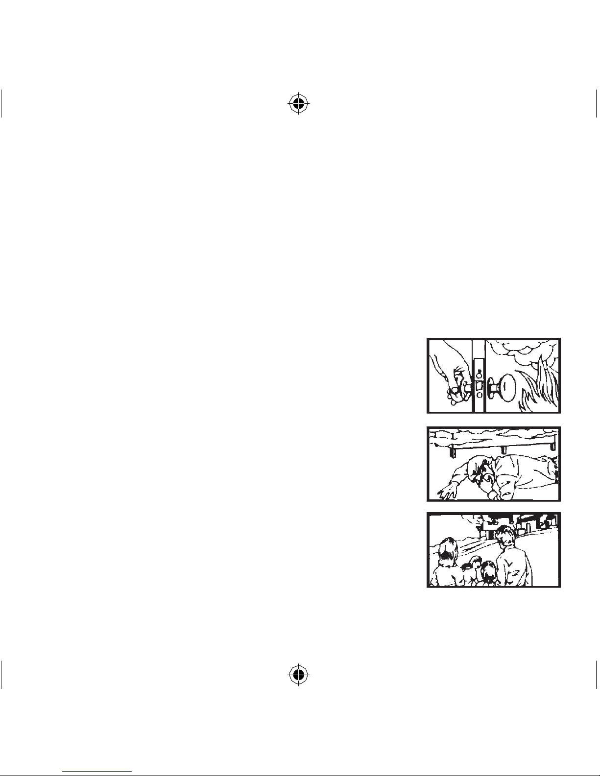
Planning Your Escape Route For When The Alarms Sound
1. Check room doors for heat or
smoke.
Do not
open
a hot door. Use an alternate escape route. Close doors
behind you as you leave.
2. If smoke is heavy, crawl out, staying close to floor. Take
short breaths, if possible, through a wet cloth or hold your
breath. More people die from smoke inhalation than from
flames.
3. Get out
as
fast
as
you can. Do not stop for
packing.
Have a prearranged meeting place outside for all family
members. Check everybody is there.
27
Page 28
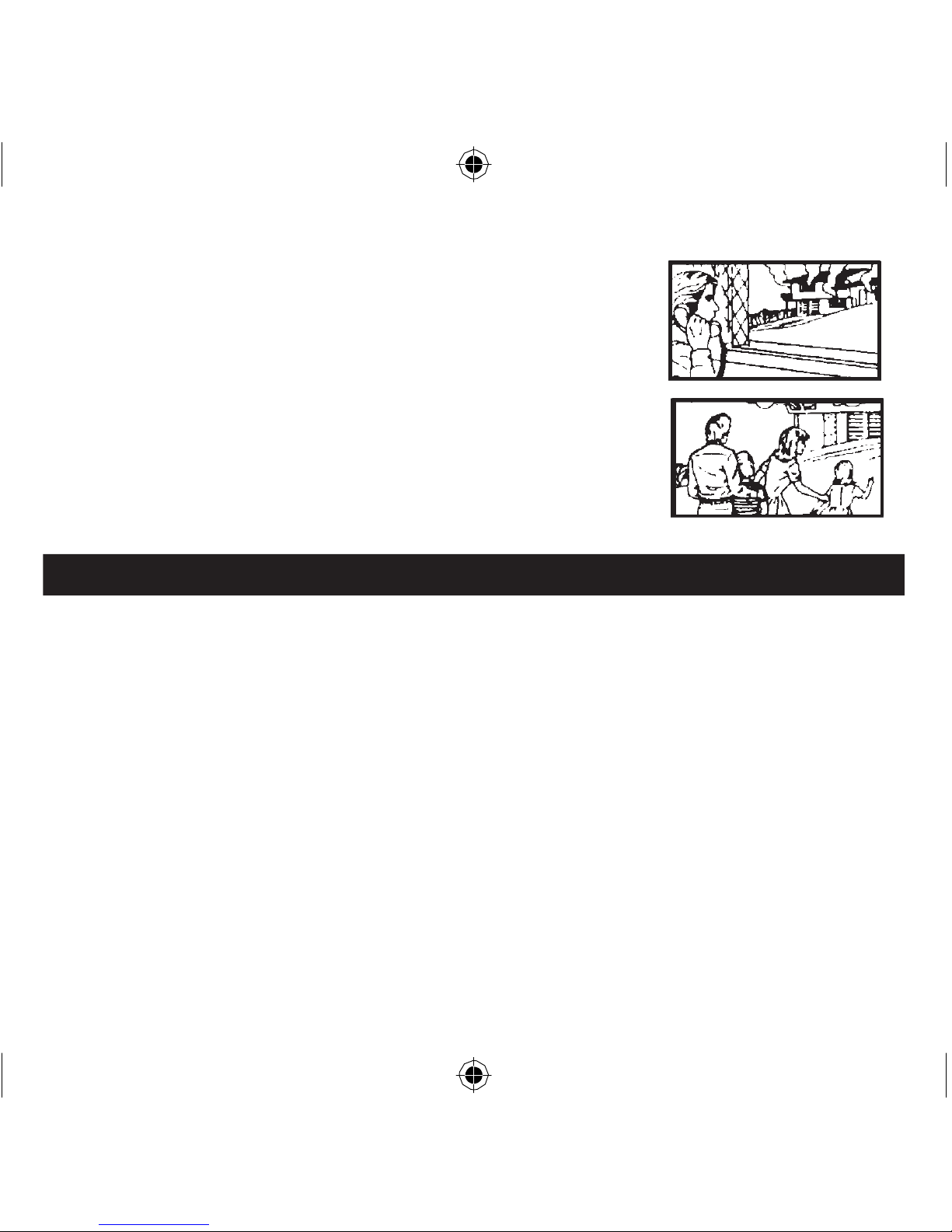
4. Call the Fire Brigade from a neighbour‟s house or
mobile phone. Remember to give your name and address.
5.
NEVER re-enter a burning house.
7. Alarm
Limitations
Limitations of Smoke/Heat Alarms
Smoke/Heat Alarms have significantly helped to reduce the number of fire fatalities
in countries where they are widely installed. However independent authorities have
stated that they may be ineffective in some circumstances. There are a number of
reasons for this:
•
Smoke/Heat
Alarms will not work
if
the
batteries
are
depleted
or
if
they are
not
connected. Test regularly and replace the entire Alarm when it fails to operate.
•
Smoke/Heat Alarms will
not
detect fire if sufficient smoke
or heat
does
not reac
h
the Alarm. Smoke/Heat may be prevented from reaching the Alarm if the fire is too far
away, for example, if the fire is on another floor, behind a closed door, in a chimney, in
a wall cavity, or if the prevailing air draughts carry the smoke or heat away. Installing
Smoke/Heat Alarms on both sides of closed doors and installing more than one Alarm
28
Page 29

Alarm Limitations
as recommended in this leaflet very significantly improve the probability of early
detection.
• The
Smoke/Heat
Alarm may not be
heard.
• RadioLINK may not work due to
interference
or due to the signal
being
blocked by furniture, renovations etc.
• A
Smoke/Heat
Alarm may not wake a
person
who has taken drugs or
alcohol.
• The Alarms
may not
detect
every type
of fire
to give sufficient early warni
ng.
They are particularly ineffective with: fires caused by smoking in bed, escaping
gas, violent explosions, poor storage of flammable rags and/or liquids, (for
example petrol, paint, spirits etc), overloaded electrical circuits, arson, children
playing with matches.
•
Smoke/Heat
Alarms don’t last indefinitely. We
recommend replacement after
10 years as a precaution.
29
Page 30

8. RadioLINK Accessories
EIB605MRF RadioLINK Interconnect module for the 9V Replaceable Battery
models. It plugs into the rear of the Alarm. This ensures that when one Alarm senses
fire, all units sound to give an alarm through-out the house - (see Table 1).
EIB605MTYRF RadioLINK Interconnect module for the 10 Year Lithium Battery
models. It plugs into the rear of the Alarm. This ensures that when one Alarm senses
fire, all units sound to give an alarm through-out the house - (see Table 1).
9. Getting Your Alarm Serviced
If your Alarm fails to work after you have read the sections on “Installation”, “Testing
and Maintenance” and “Troubleshooting”, then contact Customer Assistance at the
nearest address given at the end of this leaflet. If it needs to be returned for repair or
replacement put it in a padded box with the battery disconnected (9V Replaceable
Battery models only). The 10 Year Lithium Battery models must be removed
from the mounting plate. Send it to “Customer Assistance” at the nearest address
given on the Alarm or in this leaflet. State the nature of the fault, where the Alarm
was purchased and the date of purchase.
30
Page 31

Accessories / Alarm Servicing / Guarantee
10. Five Year Guarantee
Brooks guarantees this Alarm (excluding the battery in the 9V Replaceable
Battery models) for five years from date of purchase against any defects that
are due to faulty materials or workmanship. This guarantee only applies to
normal conditions of use and service, and does not include damage resulting
from accident, neglect, misuse, unauthorised dismantling, or contamination
howsoever caused. This guarantee excludes incidental and consequential
damage. If this Alarm should become defective within the guarantee period, it
must be returned to Brooks, with proof of purchase, carefully packaged, with
the problem clearly stated (see Section 9). We shall at our discretion repair or
replace the faulty unit.
Do not interfere with the Alarm or
attempt
to
tamper
with it. This
will
invalidate
the guarantee, but more importantly may expose the user to shock or fire
hazards.
This guarantee is in addition to your statutory rights as a consumer.
31
Page 32

11.
Troubleshooting
Alarms sound for no apparent reason
• Check for fumes,
steam,
etc. from the kitchen or
bathroom.
Paint and other
fumes
can cause nuisance alarms.
• Check for any sign of
contamination
such
as cobwebs
or dust. Clean the alarm as
described in Section 5 if necessary.
•
Press
the
Test/Hush
button on the
Smoke
Alarm
causing
the Alarm (this
can
be identified as the Alarm with the red light flashing rapidly) – this will silence the
Smoke Alarm for 10 minutes (and also silence all other interconnected Alarms in
the system).
•
Smoke
& Heat Alarms with RadioLINK
modules
should be
house coded - see
booklet „RF Modules for Battery Powered Smoke & Heat Alarms‟. If the Alarms are
in the default factory settings, neighbouring units may cause them to alarm.
•
Smoke
& Heat Alarms, with RadioLINK
modules, sound
for 2
seconds
every
4
hours - this indicates that there is a depleted battery somewhere in the system check all Alarms as outlined in section 5 “Power Supply Monitoring”.
The Alarm fails to sound when the Test button is pressed
• Check the age of the unit -
see
the “replace by” label on side of
unit.
• Check the battery
snaps
are firmly
connected
on the 9V Replaceable Battery
models.
32
Page 33

• On the 10 Year Lithium Battery models ensure the unit is twisted fully
home on the mounting plate, as this connects the battery.
33
i
600
SERIE-BROJKS
1n
cjj
33
07/1212010
Page 34
The crossed out wheelie bin symbol that is on
your
product indicates that this product should not be
disposed
of via the normal household waste stream.
Proper
disposal will prevent possible harm to the environment
or
to human health. When disposing of this product
please
separate it from other waste streams to ensure that it
can
be recycled in an environmentally sound manner.
For
more details on collection and proper disposal,
please
contact your local government office or the retailer
where
you purchased this
product.
The Smoke Alarms comply with AS 3786-1995
The Heat Alarms comply with AS 1603.3-1996
34
Page 35

35
i
600
SERIE-BROJKS
1n
cjj
35
07/1212010
Page 36

12. Contact Us
BROOKS AUSTRALIA
4 PIKE ST, RYDALMERE, NSW
2116.
1300 78
FIRE
www.brooks.com.au
© Brooks 2010 P/N B17078 Rev 0
36
 Loading...