

Page 1

Doc. no.: 9.17.079D Date: 06-02-2018
ATTENTION
Please read this Instruction Manual carefully before installing and operating the instrument.
Not following the g uidelines could result in personal injury and/or damage to the equipment.
Vapor Delivery Module
Instruction Manual
Page 2
Bronkhorst®
Instruction Manual Vapor Delivery Module 9.17.079D2
Disclaimer
The information in this manual has been reviewed and is believed to be wholly reliable. No responsibility, however, is
assumed for inaccuracies. The material in this manual is for information purposes only.
Copyright
© 2018 Bronkhorst High-Tech B.V.
All rights reserved. This documentation is protected by copyright.
Subject to technical and optical changes as well as printing errors. The information contained in this document is subject to
change at any time without prior notification. Bronkhorst High-Tech B.V. reserves the right to modify or improve its
products and modif y the contents without being obliged to inform any particular persons or organizations. The device
specifications and the contents of the package may deviate from what is stated in this document.
Symbols
Important information. Di sregarding this information could cause injuries to people or damage to t he instrument or
installation.
Helpful information. This information will facilitate t he use of the instrument and/or contribute to its optimal
performance.
Additional info available on the internet or from your l ocal sales representative.
Receipt of equipment
Check the outside package box for damage incurred during shipment. If the box is damaged, then the local carrier must be
notified at once regarding his liability, if so required. At the same time a report should be submitted to your local sales
representative.
Carefully remove the equipment from the box. Verify that the equipment was not damaged during shipment. Should the
equipment be damaged, then the local carrier must be notified at once regarding his liability, if so required. At the same
time a report should be submitted to your local sales representative.
Check the packing list t o ensure that you received all of the items within the scope of delivery.
Do not discard spare or replacement parts with the packaging material and inspect the contents for damage.
Refer to Removal and return instructions about return shipment procedures.
Equipment storage
The equipment should be stored in its original package in a cupboard warehouse or similar. Care should be taken not to
subject the equipment to excessive temperatures or humidity.
Page 3
Bronkhorst®
Instruction Manual Vapor Delivery Module9.17.079D 3
Warranty
Bronkhorst® products are warranted against defects in material and workmanship for a period of three years from the date
of shipment, provided they are used in accordance with the ordering specifications and not subject to abuse or physical
damage. Products that do not operate properly during this period may be repaired or replaced at no charge. Repairs are
normally warranted for one year or the balance of the original warranty, whichever is the longer.
See also section 9 (Guarantee) of the Conditions of sales:
www.bronkhorst.com/about/conditions-of-sales/
The warranty includes all initial and latent defects, random failures, and indeterminable internal causes.
It excludes failures and damage caused by the customer, such as contamination, improper electrical hook-up, physical shock
etc.
Re-conditioning of products primarily returned for warranty service that is partly or wholly judged non-warranty may be
charged for.
Bronkhorst High-Tech B.V. or affiliated company prepays outgoing freight charges when any part of the service is
performed under warranty, unless otherwise agreed upon beforehand, however, if the product has been returned collect to
our factory or service center, these costs are added to the repair invoice. Import and/or export charges, foreign shipping
methods/carriers are paid by the customer.
General safety precautions
This product is intended for use by qualified personnel who recognize shock hazards and are familiar with the safety
precautions required to avoid possible injury. Read the operating information carefully before using the product.
Before operating, make sure the line cord is connected to a properly grounded power receptacle. Inspect the connecting
cables for cracks or breaks before each use.
The equipment and accessories must be used in accordance with their specifications and operating instructions, otherwise
the safety of the equipment may be impaired.
If required, replace fuses with the same type and rating for continued protection against fire hazard.
Opening of the equipment is not allowed. There are no repairable parts inside. In case of a defect please return the
equipment to Bronkhorst High-Tech B.V.
One or more warning signs may be present on different parts of the product. These signs have the following meaning:
Consult t he instruction manual for handling instructions
Surface may get hot during operation
Shock hazard; electrical parts i nside
To maintain protection from electric shock and fire, replacement components must be obtained from Bronkhorst. Standard
fuses, with applicable national safety approvals, may be used if the rating and type are the same. Other components that are
not safety related may be obtained from other suppliers, as long as they are equivalent to the original component. Selected
parts should be obtained only through Bronkhorst, to maintain accuracy and functionality of the product. If you are unsure
about the relevance of a replacement component, contact Bronkhorst for information.
Page 4

Bronkhorst®
Instruction Manual Vapor Delivery Module 9.17.079D4
Page 5

Bronkhorst®
Instruction Manual Vapor Delivery Module9.17.079D 5
Table of contents
. . . . . . . . . . . . . . . . . . . . . . . . . . . . . . . . . . . . . . . . . . . . . . . . . . . . . . . . . . . . . . . . . . . . . . . . . . . . . . . . . . . . . . . . . . . . . . . . . . . . . . . . . . . . 7
Introduction 1
. . . . . . . . . . . . . . . . . . . . . . . . . . . . . . . . . . . . . . . . . . . . . . . . . . . . . . . . . . . . . . . . . . . . . . . . . . . . . . . . . . . . . . . . . . . . . . . . . . . . . . . . . . . . 71.1
Scope of this manual
. . . . . . . . . . . . . . . . . . . . . . . . . . . . . . . . . . . . . . . . . . . . . . . . . . . . . . . . . . . . . . . . . . . . . . . . . . . . . . . . . . . . . . . . . . . . . . . . . . . . . . . . . . . . 71.2
Intend ed use
. . . . . . . . . . . . . . . . . . . . . . . . . . . . . . . . . . . . . . . . . . . . . . . . . . . . . . . . . . . . . . . . . . . . . . . . . . . . . . . . . . . . . . . . . . . . . . . . . . . . . . . . . . . . 71.3
Other document s
. . . . . . . . . . . . . . . . . . . . . . . . . . . . . . . . . . . . . . . . . . . . . . . . . . . . . . . . . . . . . . . . . . . . . . . . . . . . . . . . . . . . . . . . . . . . . . . . . . . . . . . . . . . . 9
Starti ng up 2
. . . . . . . . . . . . . . . . . . . . . . . . . . . . . . . . . . . . . . . . . . . . . . . . . . . . . . . . . . . . . . . . . . . . . . . . . . . . . . . . . . . . . . . . . . . . . . . . . . . . . . . . . . . . 92.1
Functio nal proper ties
. . . . . . . . . . . . . . . . . . . . . . . . . . . . . . . . . . . . . . . . . . . . . . . . . . . . . . . . . . . . . . . . . . . . . . . . . . . . . . . . . . . . . . . . . . . . . . . . . . . . . . . . . . . . 92.2
Rated pressure test inspection
. . . . . . . . . . . . . . . . . . . . . . . . . . . . . . . . . . . . . . . . . . . . . . . . . . . . . . . . . . . . . . . . . . . . . . . . . . . . . . . . . . . . . . . . . . . . . . . . . . . . . . . . . . . . 92.3
Insta ll module
. . . . . . . . . . . . . . . . . . . . . . . . . . . . . . . . . . . . . . . . . . . . . . . . . . . . . . . . . . . . . . . . . . . . . . . . . . . . . . . . . . . . . . . . . . . . . . . . . . . . . . . . . . . . 92.4
Mod el key
. . . . . . . . . . . . . . . . . . . . . . . . . . . . . . . . . . . . . . . . . . . . . . . . . . . . . . . . . . . . . . . . . . . . . . . . . . . . . . . . . . . . . . . . . . . . . . . . . . . . . . . . . . . . 10
Techni cal spec ificati on s 3
. . . . . . . . . . . . . . . . . . . . . . . . . . . . . . . . . . . . . . . . . . . . . . . . . . . . . . . . . . . . . . . . . . . . . . . . . . . . . . . . . . . . . . . . . . . . . . . . . . . . . . . . . . . . 103.1
Physical di mensions
. . . . . . . . . . . . . . . . . . . . . . . . . . . . . . . . . . . . . . . . . . . . . . . . . . . . . . . . . . . . . . . . . . . . . . . . . . . . . . . . . . . . . . . . . . . . . . . . . . . . . . . . . . . . 103.2
Ambient condi tions
. . . . . . . . . . . . . . . . . . . . . . . . . . . . . . . . . . . . . . . . . . . . . . . . . . . . . . . . . . . . . . . . . . . . . . . . . . . . . . . . . . . . . . . . . . . . . . . . . . . . . . . . . . . . 103.3
Ingres s pro tection class
. . . . . . . . . . . . . . . . . . . . . . . . . . . . . . . . . . . . . . . . . . . . . . . . . . . . . . . . . . . . . . . . . . . . . . . . . . . . . . . . . . . . . . . . . . . . . . . . . . . . . . . . . . . . 103.4
Fluid ic con nections
. . . . . . . . . . . . . . . . . . . . . . . . . . . . . . . . . . . . . . . . . . . . . . . . . . . . . . . . . . . . . . . . . . . . . . . . . . . . . . . . . . . . . . . . . . . . . . . . . . . . . . . . . . . . 10Flow ranges of used components 3.4.1
. . . . . . . . . . . . . . . . . . . . . . . . . . . . . . . . . . . . . . . . . . . . . . . . . . . . . . . . . . . . . . . . . . . . . . . . . . . . . . . . . . . . . . . . . . . . . . . . . . . . . . . . . . . . 10Capacity 3.4.2
. . . . . . . . . . . . . . . . . . . . . . . . . . . . . . . . . . . . . . . . . . . . . . . . . . . . . . . . . . . . . . . . . . . . . . . . . . . . . . . . . . . . . . . . . . . . . . . . . . . . . . . . . . . . 11Pressure ratin g 3.4.3
. . . . . . . . . . . . . . . . . . . . . . . . . . . . . . . . . . . . . . . . . . . . . . . . . . . . . . . . . . . . . . . . . . . . . . . . . . . . . . . . . . . . . . . . . . . . . . . . . . . . . . . . . . . . 113.5
Piping
. . . . . . . . . . . . . . . . . . . . . . . . . . . . . . . . . . . . . . . . . . . . . . . . . . . . . . . . . . . . . . . . . . . . . . . . . . . . . . . . . . . . . . . . . . . . . . . . . . . . . . . . . . . . 113.6
Electrical connection s
. . . . . . . . . . . . . . . . . . . . . . . . . . . . . . . . . . . . . . . . . . . . . . . . . . . . . . . . . . . . . . . . . . . . . . . . . . . . . . . . . . . . . . . . . . . . . . . . . . . . . . . . . . . . 11Mains 3.6.1
. . . . . . . . . . . . . . . . . . . . . . . . . . . . . . . . . . . . . . . . . . . . . . . . . . . . . . . . . . . . . . . . . . . . . . . . . . . . . . . . . . . . . . . . . . . . . . . . . . . . . . . . . . . . 11Tracing 3.6.2
. . . . . . . . . . . . . . . . . . . . . . . . . . . . . . . . . . . . . . . . . . . . . . . . . . . . . . . . . . . . . . . . . . . . . . . . . . . . . . . . . . . . . . . . . . . . . . . . . . . . . . . . . . . . 12Pt100 tracing sensor 3.6.3
. . . . . . . . . . . . . . . . . . . . . . . . . . . . . . . . . . . . . . . . . . . . . . . . . . . . . . . . . . . . . . . . . . . . . . . . . . . . . . . . . . . . . . . . . . . . . . . . . . . . . . . . . . . . 12Communication 3.6.4
. . . . . . . . . . . . . . . . . . . . . . . . . . . . . . . . . . . . . . . . . . . . . . . . . . . . . . . . . . . . . . . . . . . . . . . . . . . . . . . . . . . . . . . . . . . . . . . . . . . . . . . . . . . . 12RS232 / ProPar 3.6.4.1
. . . . . . . . . . . . . . . . . . . . . . . . . . . . . . . . . . . . . . . . . . . . . . . . . . . . . . . . . . . . . . . . . . . . . . . . . . . . . . . . . . . . . . . . . . . . . . . . . . . . . . . . . . . . 12FLOW-BUS 3.6.4.2
. . . . . . . . . . . . . . . . . . . . . . . . . . . . . . . . . . . . . . . . . . . . . . . . . . . . . . . . . . . . . . . . . . . . . . . . . . . . . . . . . . . . . . . . . . . . . . . . . . . . . . . . . . . . 133.7
Conn ectors (hook- up di agram)
. . . . . . . . . . . . . . . . . . . . . . . . . . . . . . . . . . . . . . . . . . . . . . . . . . . . . . . . . . . . . . . . . . . . . . . . . . . . . . . . . . . . . . . . . . . . . . . . . . . . . . . . . . . . 14
Installation 4
. . . . . . . . . . . . . . . . . . . . . . . . . . . . . . . . . . . . . . . . . . . . . . . . . . . . . . . . . . . . . . . . . . . . . . . . . . . . . . . . . . . . . . . . . . . . . . . . . . . . . . . . . . . . 144.1
Mounting
. . . . . . . . . . . . . . . . . . . . . . . . . . . . . . . . . . . . . . . . . . . . . . . . . . . . . . . . . . . . . . . . . . . . . . . . . . . . . . . . . . . . . . . . . . . . . . . . . . . . . . . . . . . . 144.2
Fluid ic con nections
. . . . . . . . . . . . . . . . . . . . . . . . . . . . . . . . . . . . . . . . . . . . . . . . . . . . . . . . . . . . . . . . . . . . . . . . . . . . . . . . . . . . . . . . . . . . . . . . . . . . . . . . . . . . 144.3
Suppl y pressure
. . . . . . . . . . . . . . . . . . . . . . . . . . . . . . . . . . . . . . . . . . . . . . . . . . . . . . . . . . . . . . . . . . . . . . . . . . . . . . . . . . . . . . . . . . . . . . . . . . . . . . . . . . . . 144.4
Leak check
. . . . . . . . . . . . . . . . . . . . . . . . . . . . . . . . . . . . . . . . . . . . . . . . . . . . . . . . . . . . . . . . . . . . . . . . . . . . . . . . . . . . . . . . . . . . . . . . . . . . . . . . . . . . 144.5
Seals
. . . . . . . . . . . . . . . . . . . . . . . . . . . . . . . . . . . . . . . . . . . . . . . . . . . . . . . . . . . . . . . . . . . . . . . . . . . . . . . . . . . . . . . . . . . . . . . . . . . . . . . . . . . . 154.6
Purging and fill ing
. . . . . . . . . . . . . . . . . . . . . . . . . . . . . . . . . . . . . . . . . . . . . . . . . . . . . . . . . . . . . . . . . . . . . . . . . . . . . . . . . . . . . . . . . . . . . . . . . . . . . . . . . . . . 15Starting up without using vacuum 4.6.1
. . . . . . . . . . . . . . . . . . . . . . . . . . . . . . . . . . . . . . . . . . . . . . . . . . . . . . . . . . . . . . . . . . . . . . . . . . . . . . . . . . . . . . . . . . . . . . . . . . . . . . . . . . . . 15Fillin g system 4.6.1.1
. . . . . . . . . . . . . . . . . . . . . . . . . . . . . . . . . . . . . . . . . . . . . . . . . . . . . . . . . . . . . . . . . . . . . . . . . . . . . . . . . . . . . . . . . . . . . . . . . . . . . . . . . . . . 16Startin g process 4.6.1.2
. . . . . . . . . . . . . . . . . . . . . . . . . . . . . . . . . . . . . . . . . . . . . . . . . . . . . . . . . . . . . . . . . . . . . . . . . . . . . . . . . . . . . . . . . . . . . . . . . . . . . . . . . . . . 16Stoppi ng process 4.6.1.3
. . . . . . . . . . . . . . . . . . . . . . . . . . . . . . . . . . . . . . . . . . . . . . . . . . . . . . . . . . . . . . . . . . . . . . . . . . . . . . . . . . . . . . . . . . . . . . . . . . . . . . . . . . . . 16Leaving system overnigh t 4.6.1.4
. . . . . . . . . . . . . . . . . . . . . . . . . . . . . . . . . . . . . . . . . . . . . . . . . . . . . . . . . . . . . . . . . . . . . . . . . . . . . . . . . . . . . . . . . . . . . . . . . . . . . . . . . . . . 16Emptying and purging system 4.6.1.5
. . . . . . . . . . . . . . . . . . . . . . . . . . . . . . . . . . . . . . . . . . . . . . . . . . . . . . . . . . . . . . . . . . . . . . . . . . . . . . . . . . . . . . . . . . . . . . . . . . . . . . . . . . . . 17Starting u p usin g vacuum 4.6.2
. . . . . . . . . . . . . . . . . . . . . . . . . . . . . . . . . . . . . . . . . . . . . . . . . . . . . . . . . . . . . . . . . . . . . . . . . . . . . . . . . . . . . . . . . . . . . . . . . . . . . . . . . . . . 17Fillin g system 4.6.2.1
. . . . . . . . . . . . . . . . . . . . . . . . . . . . . . . . . . . . . . . . . . . . . . . . . . . . . . . . . . . . . . . . . . . . . . . . . . . . . . . . . . . . . . . . . . . . . . . . . . . . . . . . . . . . 17Startin g process 4.6.2.2
. . . . . . . . . . . . . . . . . . . . . . . . . . . . . . . . . . . . . . . . . . . . . . . . . . . . . . . . . . . . . . . . . . . . . . . . . . . . . . . . . . . . . . . . . . . . . . . . . . . . . . . . . . . . 18Stoppi ng process 4.6.2.3
. . . . . . . . . . . . . . . . . . . . . . . . . . . . . . . . . . . . . . . . . . . . . . . . . . . . . . . . . . . . . . . . . . . . . . . . . . . . . . . . . . . . . . . . . . . . . . . . . . . . . . . . . . . . 18Leaving system overnigh t 4.6.2.4
. . . . . . . . . . . . . . . . . . . . . . . . . . . . . . . . . . . . . . . . . . . . . . . . . . . . . . . . . . . . . . . . . . . . . . . . . . . . . . . . . . . . . . . . . . . . . . . . . . . . . . . . . . . . 18Emptying and purging system 4.6.2.5
. . . . . . . . . . . . . . . . . . . . . . . . . . . . . . . . . . . . . . . . . . . . . . . . . . . . . . . . . . . . . . . . . . . . . . . . . . . . . . . . . . . . . . . . . . . . . . . . . . . . . . . . . . . . 19
Operation 5
Page 6

Bronkhorst®
Instruction Manual Vapor Delivery Module 9.17.079D6
. . . . . . . . . . . . . . . . . . . . . . . . . . . . . . . . . . . . . . . . . . . . . . . . . . . . . . . . . . . . . . . . . . . . . . . . . . . . . . . . . . . . . . . . . . . . . . . . . . . . . . . . . . . . 195.1
Powering u p
. . . . . . . . . . . . . . . . . . . . . . . . . . . . . . . . . . . . . . . . . . . . . . . . . . . . . . . . . . . . . . . . . . . . . . . . . . . . . . . . . . . . . . . . . . . . . . . . . . . . . . . . . . . . 195.2
User inter face
. . . . . . . . . . . . . . . . . . . . . . . . . . . . . . . . . . . . . . . . . . . . . . . . . . . . . . . . . . . . . . . . . . . . . . . . . . . . . . . . . . . . . . . . . . . . . . . . . . . . . . . . . . . . 19Buttons 5.2.1
. . . . . . . . . . . . . . . . . . . . . . . . . . . . . . . . . . . . . . . . . . . . . . . . . . . . . . . . . . . . . . . . . . . . . . . . . . . . . . . . . . . . . . . . . . . . . . . . . . . . . . . . . . . . 19Display 5.2.2
. . . . . . . . . . . . . . . . . . . . . . . . . . . . . . . . . . . . . . . . . . . . . . . . . . . . . . . . . . . . . . . . . . . . . . . . . . . . . . . . . . . . . . . . . . . . . . . . . . . . . . . . . . . . 20Select instru ment 5.2.3
. . . . . . . . . . . . . . . . . . . . . . . . . . . . . . . . . . . . . . . . . . . . . . . . . . . . . . . . . . . . . . . . . . . . . . . . . . . . . . . . . . . . . . . . . . . . . . . . . . . . . . . . . . . . 21Temperature and flow setpoints 5.2.4
. . . . . . . . . . . . . . . . . . . . . . . . . . . . . . . . . . . . . . . . . . . . . . . . . . . . . . . . . . . . . . . . . . . . . . . . . . . . . . . . . . . . . . . . . . . . . . . . . . . . . . . . . . . . 215.3
Operation al settings
. . . . . . . . . . . . . . . . . . . . . . . . . . . . . . . . . . . . . . . . . . . . . . . . . . . . . . . . . . . . . . . . . . . . . . . . . . . . . . . . . . . . . . . . . . . . . . . . . . . . . . . . . . . . 22Operation example 5.3.1
. . . . . . . . . . . . . . . . . . . . . . . . . . . . . . . . . . . . . . . . . . . . . . . . . . . . . . . . . . . . . . . . . . . . . . . . . . . . . . . . . . . . . . . . . . . . . . . . . . . . . . . . . . . . 23Vapor pressure of water 5.3.2
. . . . . . . . . . . . . . . . . . . . . . . . . . . . . . . . . . . . . . . . . . . . . . . . . . . . . . . . . . . . . . . . . . . . . . . . . . . . . . . . . . . . . . . . . . . . . . . . . . . . . . . . . . . . 24
Troub lesho oti ng and service 6
. . . . . . . . . . . . . . . . . . . . . . . . . . . . . . . . . . . . . . . . . . . . . . . . . . . . . . . . . . . . . . . . . . . . . . . . . . . . . . . . . . . . . . . . . . . . . . . . . . . . . . . . . . . . 246.1
Common issues
. . . . . . . . . . . . . . . . . . . . . . . . . . . . . . . . . . . . . . . . . . . . . . . . . . . . . . . . . . . . . . . . . . . . . . . . . . . . . . . . . . . . . . . . . . . . . . . . . . . . . . . . . . . . 256.2
Maintenance
. . . . . . . . . . . . . . . . . . . . . . . . . . . . . . . . . . . . . . . . . . . . . . . . . . . . . . . . . . . . . . . . . . . . . . . . . . . . . . . . . . . . . . . . . . . . . . . . . . . . . . . . . . . . 256.3
Service
. . . . . . . . . . . . . . . . . . . . . . . . . . . . . . . . . . . . . . . . . . . . . . . . . . . . . . . . . . . . . . . . . . . . . . . . . . . . . . . . . . . . . . . . . . . . . . . . . . . . . . . . . . . . 26
Remova l and return i nstruct ions 7
Page 7
Bronkhorst®
Instruction Manual Vapor Delivery Module9.17.079D 7
1
Introduction
1.1 Scope of this manual
This manual contains general product information, installation and operating instructions and troubleshooting tips for the
Vapor Delivery Module (VDM).
1.2 Intended use
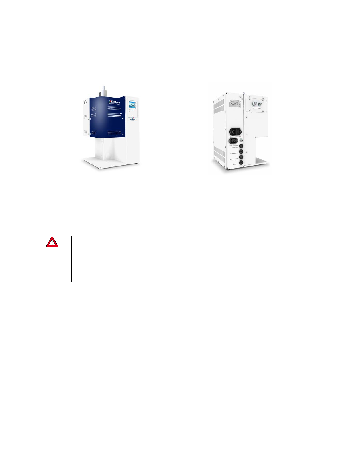
The VDM is a compact integrated system to realize mass flow control of a vapor. The VDM is intended to generate a
predefined vapor f low, accruing from an accurately controlled liquid mass flow injected into an accurately controlled carrier
gas flow with subsequent evaporation inside a temperature controlled chamber.
The user is considered to be familiar and to comply with the necessary safety precautions and appropriate protective
measures as described in the Material Safety Data Sheets of the media to be used in the system.
The end user i s considered to be familiar with the necessary safety precautions, and to comply with the appropriate
protective measures as described in the Material S afety Data Sheets of the media to be used in the system (if applicable).
Responsibility for the use of the equipment with regard to suitability, intended use, cleaning and corrosion resistance of the
used materials against the metered media lies solely with the end user.
Bronkhorst H igh-Tech B.V. cannot be held liable for any damage resulting from i mproper use or use for other than the
intended purpose.
1.3 Other documents
Manuals and guides for digital instruments are modular. General instructions give information about the functioning and
installation of instruments. Operational instructions explain the use of the digital instruments features and parameters.
Field bus specific information explains the installation and use of the field bus installed on the instrument.
The following documents contain information for basic and advanced operation, more detailed product information and
troubleshooting tips:
· Instruction manual FLOW-BUS interface (document nr. 9.17.024)
· Instruction manual RS232 interface with FLOW-BUS protocol (document nr. 9.17.027)
· Instru ction manu al E-8000 Readout and Control System (document nr. 9.17.076)
For RS232 or FLOW-BUS operation the following Bronkhorst software is available:
· FlowDDE
Interface between digital instruments and Windows software
· FlowView
Operating Bronkhorst digital instruments
· Flowfix
Fieldbus connection of digital instruments
· FlowP lot
Monitoring and optimizing digital instrument parameters
Page 8

Bronkhorst®
Instruction Manual Vapor Delivery Module 9.17.079D8
Manuals and software tooling can be found at
http://www.bronkhorst.com/en/downloads
Page 9
Bronkhorst®
Instruction Manual Vapor Delivery Module9.17.079D 9
2
Starting up
2.1 Functional properties
Before installing the VDM, check if the functional properties match your requirements:
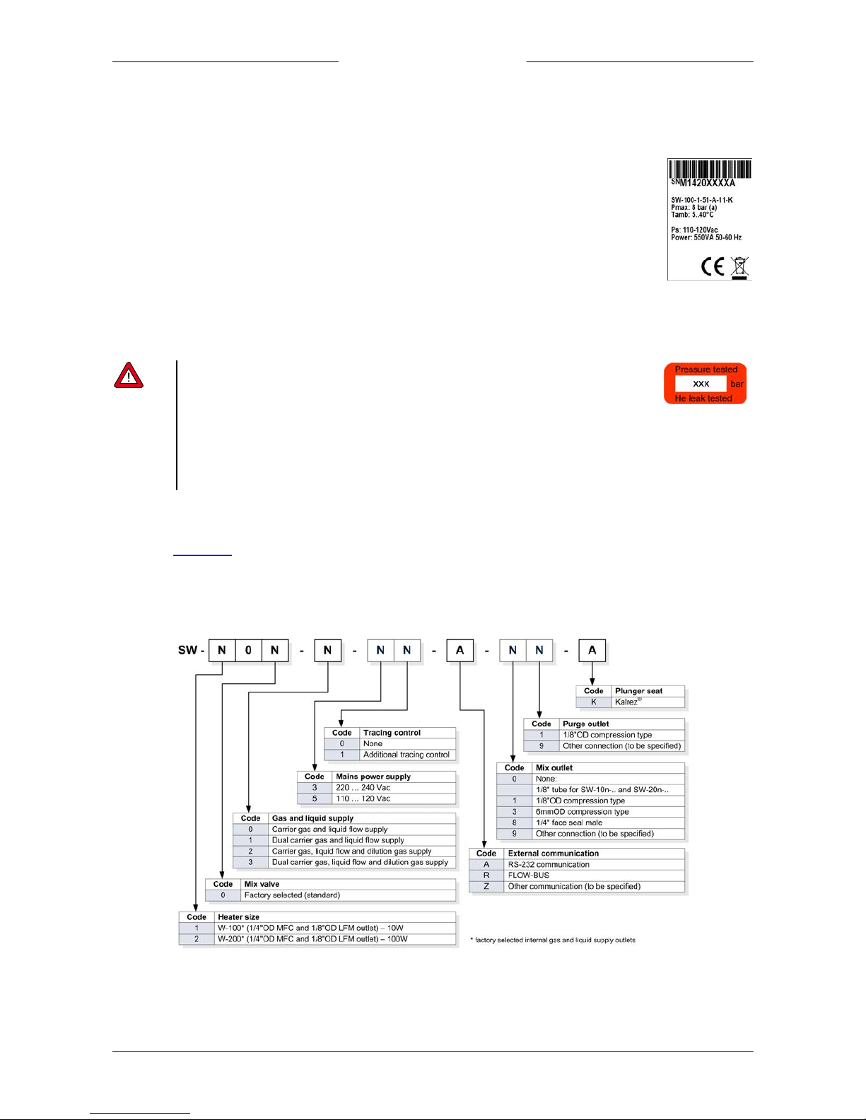
· Model key
· Pressure rate
· Temperature (ambient)
· Power supply
· Power consumption
2.2 Rated pressure test inspection
Bronkhorst® i nstruments are pressure tested to at least 1. 5 times the specified working process
conditions and outboard leak tested to at least 2 * 10-9 mbar l /s Helium. The tested pressure is specified
on the instrument with a red sticker. If t his sticker is missing or if the specified pressure is insufficient,
the instrument must not be used and should be returned to the factory.
Before installation, make sure that the tested pressure is in accordance with the safety factor of your application. The tested
pressure must always be higher than the maximum operating pressure.
Disassembling the instrument and/or replacing parts of it will invalidate the pressure test specification.
2.3 Install module
See section Installation for detailed installation instructions.
Before switching on power, please check if all external electrical and communication (if necessary) connections are properly
connected.
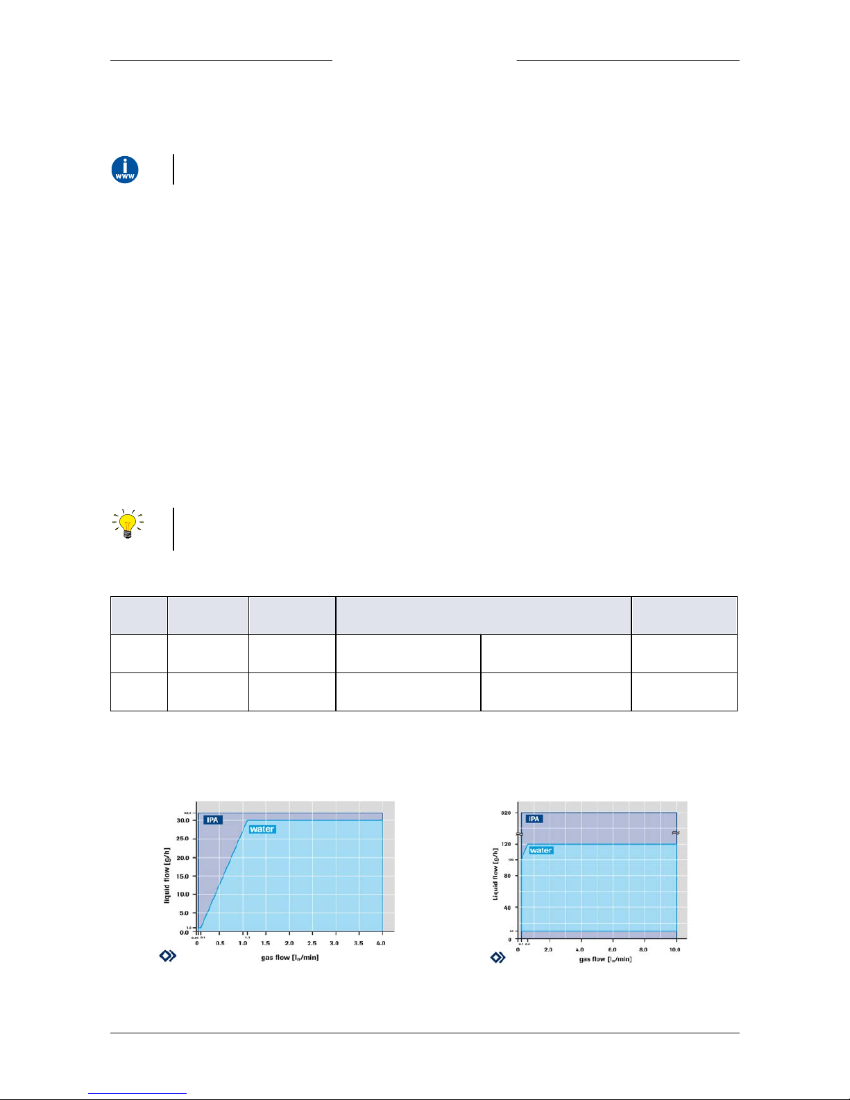
2.4 Model key
Page 10
Bronkhorst®
Instruction Manual Vapor Delivery Module 9.17.079D10
3
Technical specifications
3.1 Physical dimensions
For overall dimensions please consult supplied dimensional drawing 7.05. 901. This document is available on
http://www.bronkhorst.com/en/downloa ds or can be obtained by contacting our local sales & service representatives
3.2 Ambient conditions
· Ambient temperature : 5°C - 40°C.
· Relative humidity : Maximum relative humidity 80%, for temperatures up to 31°C decreasing linearly
to 50% relative humidity at 40°C.
· Heigh t a ltitude : Up to 2000 m.
3.3 Ingress protection class
IP20, according IEC standard 60529.
3.4 Fluidic connections
The VDM gas and liquid supply are equipped with compression type or face-seal-fittings. Normally these fittings are BSP
parallel threads types which have to be used in combination with elastomeric O-rings to seal to the VDM. Occasionally
fittings are orbital welded to the VDM.
For leak tight installation of compression type fittings be sure that the tube is inserted to the shoulder in the fitting body
and that no dirt or dust is present on tube, ferrules or fittings.
For exact information on the fitting, please contact Swagelok for further instructions or documentation.
Always check your system for leaks, before applying fluid pressure. E specially if toxic, explosive or other dangerous fluids are
used.
3.4.1 Flow ranges of used components
Model
Heater
model
Thermal
power
Max. capacity
*
Max temp.
SW10n
W-100A
10 W
1…30 g/h liquid
0.05…4 ln/min gas
200°C
SW20n
W-200A
100 W
10…120 g/h liquid
0.2…10 ln/min gas
200°C
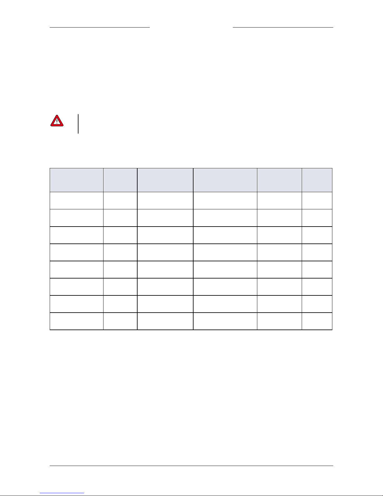
*) Depending on liquid and process pressure; table based on water at 1 atmosphere.
For other liquids or pressure conditions please consult the manufacturer or your local sales representative.
3.4.2 Capacity
Capacity SW- 100 V aporizer
Capacity SW- 200 V aporizer
Page 11
Bronkhorst®
Instruction Manual Vapor Delivery Module9.17.079D 11
3.4.3 Pressure rating
· Gas supply = max. 10 bar(g)
· Liquid supply = max. 10 bar(g)
· Vapor pressure = atmospheric
3.5 Piping
For optimal performance of the system it is recommend to have at least 10 pipe diameters distance between the angle and
the equipment inlets. The purge is rarely used in production environments, except for installation.
Be sure that piping is absolutely clean!
CAUTION - DO NOT i nstall small diameter piping on high flow rates.
CAUTION - DO NOT m ount abrupt angles directly to the inlet or outlet, especially for high flow rates.
3.6 Electrical connections
3.6.1 Mains
Model
Power
supply
(Vac)
Maximum power
(tracing included)
Fuse primary heater
Fuse secondary
heater
Fuse
main
SW-10n-n-50-ann-a
110 … 120
250VA 50-60 Hz
T2A I2t >30A
Littelf use 0213002.MXP*
T4A
T2A
SW-10n-n-51-ann-a
110 … 120
550VA 50-60 Hz
T2A I2t >30A
Littelfuse 0213002.MXP*
T4A
T2A
SW-20n-n-50-ann-a
110 … 120
250VA 50-60 Hz
T2A I2t >30A
Littelfuse 0213002.MXP*
T4A
T2A
SW-20n-n-51-ann-a
110 … 120
550VA 50-60 Hz
T2A I2t >30A
Littelfuse 0213002.MXP*
T4A
T2A
SW-10n-n-30-ann-a
220 … 240
250VA 50-60 Hz
T1A I2t >10A
Littelfuse 0213001.MXP*
T4A
T1A
SW-10n-n-31-ann-a
220 … 240
550VA 50-60 Hz
T1A I2t >10A
Littelfuse 0213001.MXP*
T4A
T1A
SW-20n-n-30-ann-a
220 … 240
250VA 50-60 Hz
T1A I2t >10A
Littelfuse 0213001.MXP*
T4A
T1A
SW-20n-n-31-ann-a
220 … 240
550VA 50-60 Hz
T1A I2t >10A
Littelfuse 0213001.MXP*
T4A
T1A
* Littelfuse or equivalent
For mains connection, use appropriate cabling with IEC 60320-1/C19 connector:
· Power cable with Euro Plug (EU) – Schurter #6051.2043 (art.nr.1.15.242)
· Power cable with Switzerland Plug (CH) (art.nr.1.15.243)
· Power cable with North America Plug (USA) – Schurter #6051.2041 (art.nr.1.15.244)
· Power cable with United Kingdom Plug (UK) – Schurter #6051.2048 (art.nr.1.15.245)
3.6.2 Tracing
Optionally, the VDM can be provided with a trace temperature control. In this case, the VDM Series is equipped with a
tracing output IEC 60320-2-2 / C13 female connector. This connector is intended for connecting tracing tape, which is not
supplied. The voltage at this tracing output is equal to the supply voltage of the VDM.
For tracing connection, use appropriate cabling with IEC 60320-2-2/C14 plug (art.nr. 1.09.594). Make sure cabling is double
isolated.
The table below shows the maximum tracing power and the fuse amperage for the various models.
Page 12
Bronkhorst®
Instruction Manual Vapor Delivery Module 9.17.079D12
Model
Power supply (Vac)
Maximum tracing power
Fuse tracing heater
SW-10n-n-51-ann-a
110 … 120
300 VA 50-60 Hz
T2,5A
SW-20n-n-51-ann-a
110 … 120
300 VA 50-60 Hz
T2,5A
SW-10n-n-31-ann-a
220 … 240
300 VA 50-60 Hz
T1,25A
SW-20n-n-31-ann-a
220 … 240
300 VA 50-60 Hz
T1,25A
3.6.3 Pt100 tracing sensor
Optionally, the VDM can be provided with a trace temperature control. In this case, the VDM Series is equipped with a Pt100
inlet 4-pin M12 A-coded male connector. This connector is intended for connecting a two, three or four-wire Pt100.
Measurement current through the sensor is 0,5 mA.
For Pt100 connection, use appropriate cabling with M12 4-pin female connector (art.nr. 1.09.593).
Make sure that the temperature sensor is properly mounted with the tracing wire, otherwise no temperature control is
possible and hazardous situations may occur.
3.6.4 Communication
3.6.4.1 RS232 / ProPar
For further instructions about the RS232 i nterface see manual 9.1 7.027 Manual 'RS232 interface with FLOW-BUS protocol
for digital i nstruments'. This manual is available at the download section of our website:
http://www.bronkhorst.com/en/downloa ds
3.6.4.2 FLOW-BUS
For further instructions about the FLOW-BUS interface see manual 9. 17.024 Manual 'F LOW-BUS i nterface for digital
instruments'. T his m anual is available at the download section of our website:
http://www.bronkhorst.com/en/downloa ds
Page 13
Bronkhorst®
Instruction Manual Vapor Delivery Module9.17.079D 13
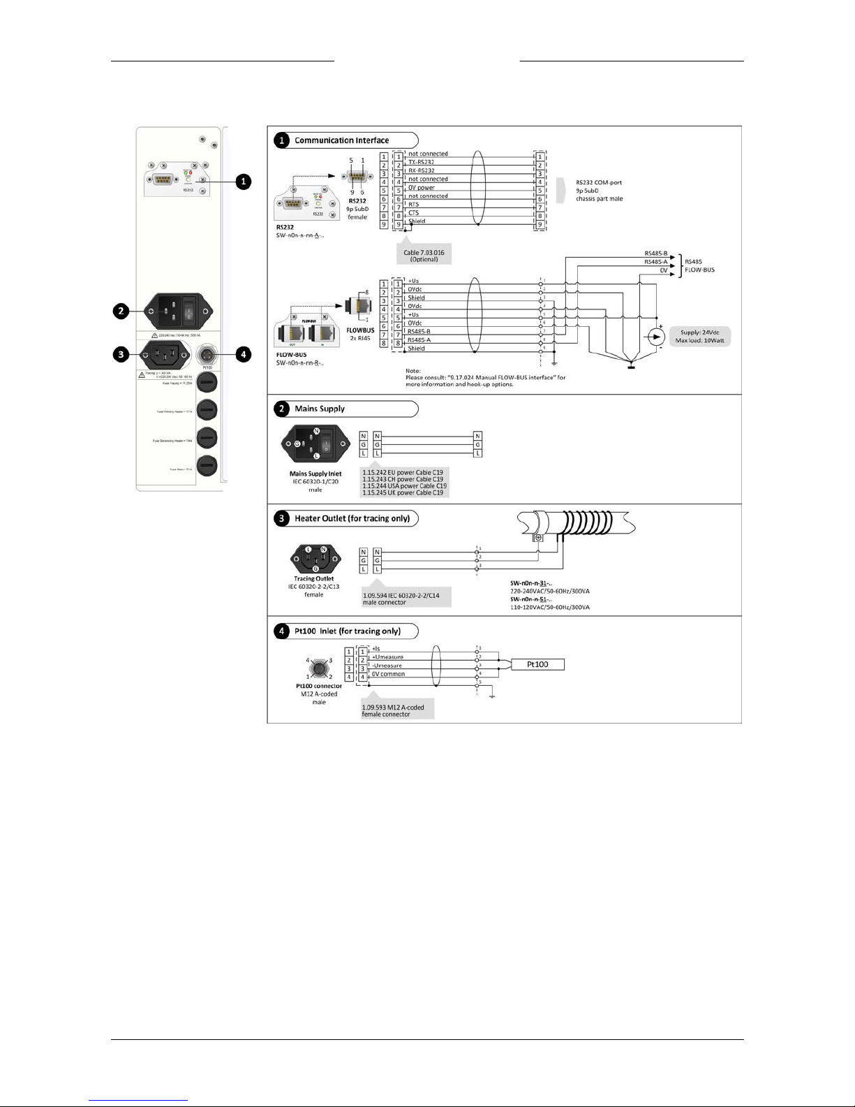
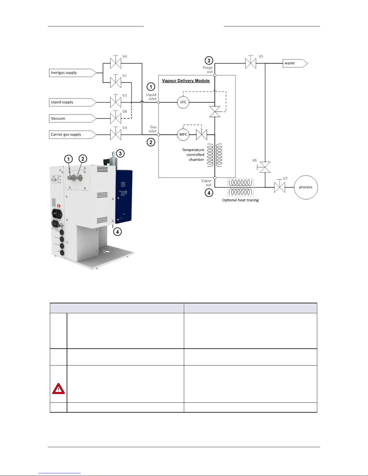
3.7 Connectors (hook-up diagram)
Page 14
Bronkhorst®
Instruction Manual Vapor Delivery Module 9.17.079D14
4
Installation
4.1 Mounting
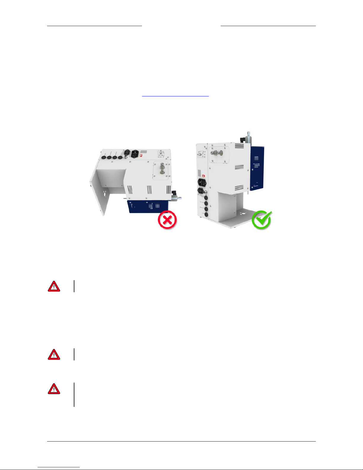
The mounting position of the equipment is upright. Please take attention:
· Avoid installation in close proximity of mechanic vibration and/or heat sources.
· Avoid contact between hot surfaces of the enclosure with electrical cables and fluidic hoses/pipes.
· Ventilation requires a minimum distance of 100 mm space from each side to a wall.
· Make use of the protective earth pin (see Connectors (hook-up diagram), connector 3) for grounding the connected
tubing. Use an appropriate cable.
· Mount the equipment in such a way, that cables and mains switches can easily be reached and disconnected.
4.2 Fluidic connections
For exact information on the fittings, please contact Swagelok for further instructions or documentation.
Please be aware when using Oxygen (O2) that the fittings mounted in the gas line should be absolutely oxygen clean.
4.3 Supply pressure
Do not apply pressure until electrical connections are made. When applying pressure to the system, make sure that the
pressure is increased gradually and avoid pressure shocks in the system.
4.4 Leak check
Check the system for leaks before applying pressure, especially if t oxic, explosive or other dangerous fluids are used.
4.5 Seals
Bronkhorst has gathered a material compatibili ty chart from a number of sources believed to be reliable. However, it is a
general guide only. Operating conditions may substantially change the accuracy of this guide. T herefore there is no liability
for damages accruing from the use of this guide. The customer’s application will demand its own specific design or test
evaluation for optimum reliabilit y. So check order documentation if t he used seals are correct for the process.
Page 15
Bronkhorst®
Instruction Manual Vapor Delivery Module9.17.079D 15
4.6 Purging and filling
4.6.1 Starting up without using vacuum
4.6.1.1 Filling system
Procedure
Actions
A1
Purge all lines
· Close V2, V3 and V7
· Open V1, V4, V5 and V6
· Give setpoint 100% to MFC
· Give setpoint 0% to LFC
· Purge for a long time.
A2
Setup carrier gas supply
· Close V4
· Open V3
A3
Fill the system with liquid.
· Close V1
· Open V2 briefly; allow mixing valve VDM to fill.
· Wait until all gas bubbles left the system via Purge out
and V5, then close V5.
Make sure that the carrier gas is always flowing when
the liquid flow is on. It is preferred to always have gas
flowing in the carrier gas line when the system is filled
with liquid.
A4
The system is now ready for use.
Page 16
Bronkhorst®
Instruction Manual Vapor Delivery Module 9.17.079D16
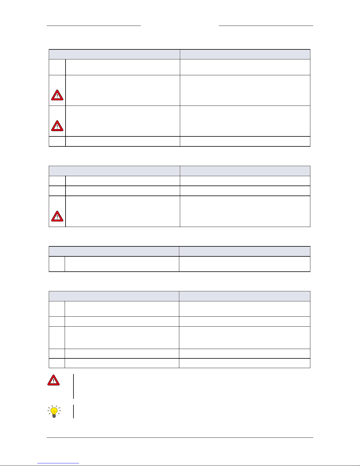
4.6.1.2 Starting process
Procedure
Actions
B1
Set the heater at right temperature
· Give set point to the heater; wait until the
temperature is stabilized
B2
Start gas flow
· Give setpoint to MFC
Make sure that the carrier gas is always flowing when
the liquid flow is on. Preferably, let always gas flow in
the carrier gas line when the system i s filled with liquid.
B3
Start liquid flow
· Give setpoint LFC, wait until stabilization
Close supply pressure of the liquid vessel during the
process. The pressure controller of t he inert gas supply
can influence the stability of the liquid flow controller.
B4
Connect process
· Open V7, close V6
4.6.1.3 Stopping process
Procedure
Actions
C1
Disconnect process
· Open V6, close V7
C2
Stop liquid flow
· Give setpoint = 0 to LFC
C3
Optional: Stop gas flow
· Give setpoint = 0 to MFC
Make sure that the carrier gas is always flowing when
the liquid flow is on. Preferably, let always gas flow in
the carrier gas line when the system i s filled with liquid.
4.6.1.4 Leaving system overnight
Procedure
Actions
D1
Relieve the supply pressure from the liquid- and
carrier gas lines
· Close V2 and V3
4.6.1.5 Emptying and purging system
Procedure
(1,2)
Actions
E1
Relieve the supply pressure from the liquid- and
carrier gas lines
· Close V2 and V3
E2
Purge liquid out of lines
· Open V1 and V5
E3
Purge lines with inert gas
· Open V4, V6
· Close V7
· Give setpoint to MFC
E4
Optional: purge with inert liquid
Connect inert liquid to inert gas supply, proceed from E2
E5
Optional: alter E3 and E4 for a few times
(1)
If the li quid is reactive or aggressive, be sure to remove air (and water vapor) carefully, before introducing liquid in the
system.
(2)
If the li quid is reactive, aggressive, poisonous, toxic, or flammable, beware that the system is purged fully (preferably with
inert liquid, E3, E 4, E 5) before opening the system.
· In case of non-pure li quids, place a filt er upstream the liquid flow controller.
· Mount the VDM upright.
Page 17
Bronkhorst®
Instruction Manual Vapor Delivery Module9.17.079D 17
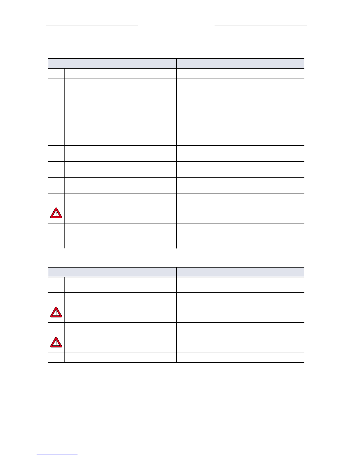
4.6.2 Starting up using vacuum
4.6.2.1 Filling system
Procedure
Actions
A1
Evacuate the lines “Vacuum”
· Start pumps
A2
Evacuate all lines
· Close: V1, V2, V3, V4, and V6
· Make sure that “waste” and “process” are vacuum
· Connect inert gas on carrier gas inle.
· Open : V5 and V8
· Give setpoint to gas and liquid control (the control
valves of the LFC and MFC open)
· Pump for a long time
· Remark: if the system is not completely dry follow
procedure of E3, E4, (E5)
A3
Purge line between inert gas source and valve V1
· Open valve V1 briefly for some seconds.
A4
Purge line between process gas source and gas
MFC
· Give setpoint = 0 to LFM (mix valve closes)
· Open valve V3 briefly for some seconds
A5
Pump down liquid supply
· Open V2 for some time
· Close V2
A6
Setup carrier gas
· Close V8
· Open V3
A7
Fill the system with liquid
· Close V1
· Open B2 briefly; allow mixing valve VDM to fill
· Close V5
Make sure that the carrier gas is always flowing when
the liquid flow is on. Preferably, let always gas flow in
the carrier gas line when the system i s filled with liquid.
A8
Optional: degassing mixing valve
· Open V5, a needle valve will be best, to avoid too
much liquid be pumped away
A9
The system is now ready for use
4.6.2.2 Starting process
Procedure
Actions
B1
Set the heater at right temperature
· Give setpoint to the heater, wait until temperature is
reached
B2
Start gas flow
· Give setpoint to MFC
Make sure that the carrier gas is always flowing when
the liquid flow is on. Preferably, let always gas flow in
the carrier gas line when the system i s filled with liquid.
B3
Start liquid flow
· Give setpoint LFC, wait until stabilization
Close supply pressure of the liquid vessel during the
process. The pressure controller of t he inert gas supply
can influence the stability of the liquid flow controller.
B4
Connect process
· Open V7, close V6
Page 18
Bronkhorst®
Instruction Manual Vapor Delivery Module 9.17.079D18
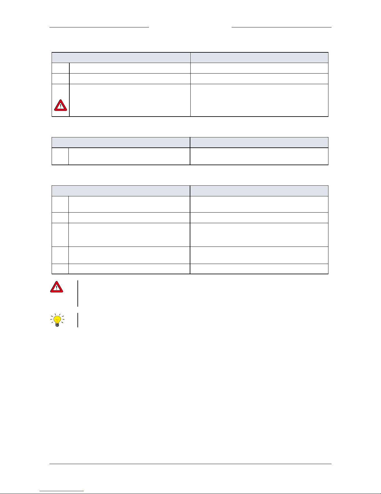
4.6.2.3 Stopping process
Procedure
Actions
C1
Disconnect process
· Open V6, close V7
C2
Stop liquid flow
· Give setpoint = 0 to LFC
C3
Optional: Stop gas flow
· Give setpoint = 0 to MFC
Make sure that the carrier gas is always flowing when
the liquid flow is on. Preferably, let always gas flow in
the carrier gas line when the system i s filled with liquid.
4.6.2.4 Leaving system overnight
Procedure
Actions
D1
Relieve the supply pressure from the liquid- and
carrier gas lines
· Close V2
· Open V8 f or some seconds
4.6.2.5 Emptying and purging system
Procedure
(1,2)
Actions
E1
Relieve the supply pressure from the liquid- and
carrier gas lines
· Close V2 and V3
E2
Purge liquid out of lines
· Open V1 and V4
E3
Purge lines with inert gas
· Open V4 and V6
· Close V7
· Give setpoint to MFC
E4
Evacuate liquid lines (cont.)
· Close V1
· Open V8
E5
Optional: repeat last two steps f or a few times
(1)
If the li quid is reactive or aggressive, be sure to remove air (and water vapor) carefully, before introducing liquid in the
system.
(2)
If the li quid is reactive, aggressive, poisonous, toxic, or flammable, beware that the system is purged fully (preferably with
inert liquid, E3, E 4, E 5) before opening the system.
· In case of non-pure li quids, place a filt er upstream the liquid flow controller.
· Mount the VDM upright.
Page 19
Bronkhorst®
Instruction Manual Vapor Delivery Module9.17.079D 19
5
Operation
5.1 Powering up
Before switching on the power, be sure that:
· System is checked for leakage of gases and liquids
· All connections have been made
· Flow-set points are zero
· No liquid has been spilled into the equipment
Switch on and then:
· Allow 30 minutes (from switching on) to warm up (common for thermal flow controllers)
· Wait until temperatures setpoints are reached. When the LED indicators turn blue, temperature
setpoints are reached.
· Make sure that the carrier gas is always flowing before the liquid flow setpoint is applied.
5.2 User interface
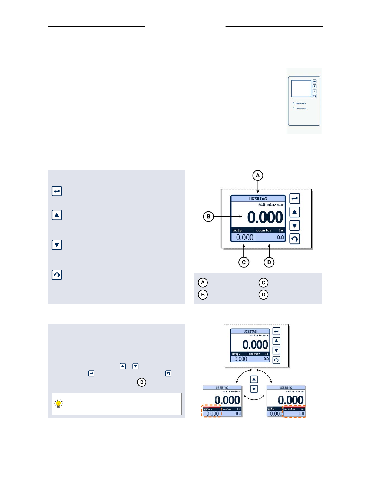
5.2.1 Buttons
The buttons have the following functions:
- Enter selected menu
- Enter edit mode
- Confirm selection/changes
- Menu selection up
- Select information field
- Next character in edit mode
- Up in table
- Menu selection down
- Select information field
- Previous character in edit mode
- Down in table
- Return to previous screen
- Undo, cancel and exit edit mode
- Switch content in the 'Custom readout 2' field
Top line
Custom readout 1
Measure readout
Custom readout 2
5.2.2 Display
The display is divided into 4 areas, ‘Measure readout’,
‘Custom readout 1’, ‘Custom readout 2’ and the 'Top line'.
The information in these areas can be configured by the
user.
If an area contains a parameter which can be set or reset
by the operator, you can press
or
to select this
parameter. Press
to enter the edit mode or press
to
return to the ‘Measure readout’ screen .
If ‘Custom readout 1’ is disabled, you can only
switch between ‘Measure readout’ and ‘Custom
readout 2’.
Page 20
Bronkhorst®
Instruction Manual Vapor Delivery Module 9.17.079D20
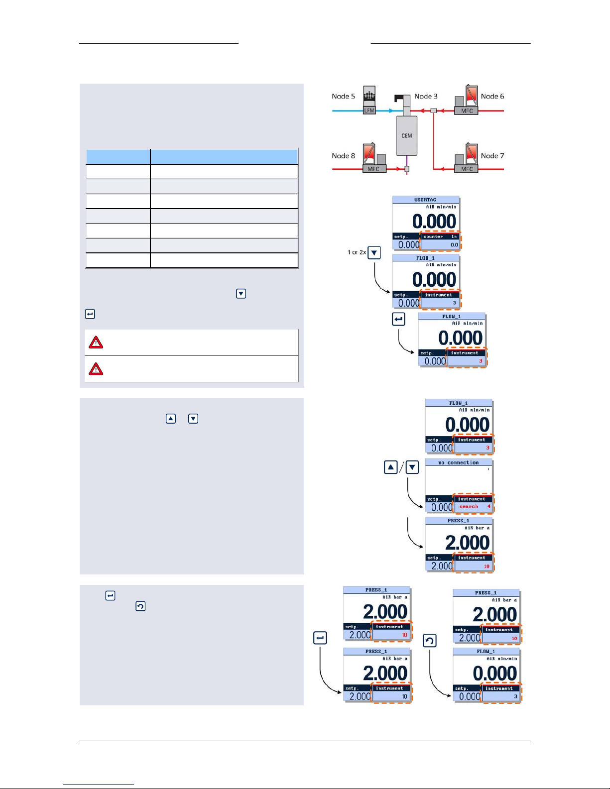
5.2.3 Select instrument
The Vapor Delivery Modules contains liquid and gas flow
controllers. Also a temperature controller for evaporation
and optional trace heating is provided. These integrated
instruments have unique node addresses. Factory default
node addresses are:
Node address
Instrument
2
Readout and control (Display)
3
Temp. controlled evaporation device
4*
Trace heating temperature control
5
Liquid flow supply
6
Carrier gas supply
7*
Second carrier gas supply
8*
Dilution gas supply
* = if applicable
To enter the 'instrument' mode, press the button until
the red line appears above 'Custom readout 2' than press
to activate this field.
Security settings can be set to avoid
unauthorised access to this option.
The number of displays that have the same
instrument selected must not exceed 3.
The integrated Instruments will be indicated with their
node addresses . Press or to search for an
instrument on the bus. While the message “search” is
displayed, the VDM is searching for a valid node address
and it will not show any specific instrument inf o until an
active node is found.
When an active node address is found, the VDM will show
the corresponding USERTAG or Serial Number in the 'Top
line'. It will also show the actual measure and, if applicable,
the actual setpoint.
Press to select this instrument to be operated by the
VDM or press to return to the previous selected
instrument.
Page 21
Bronkhorst®
Instruction Manual Vapor Delivery Module9.17.079D 21
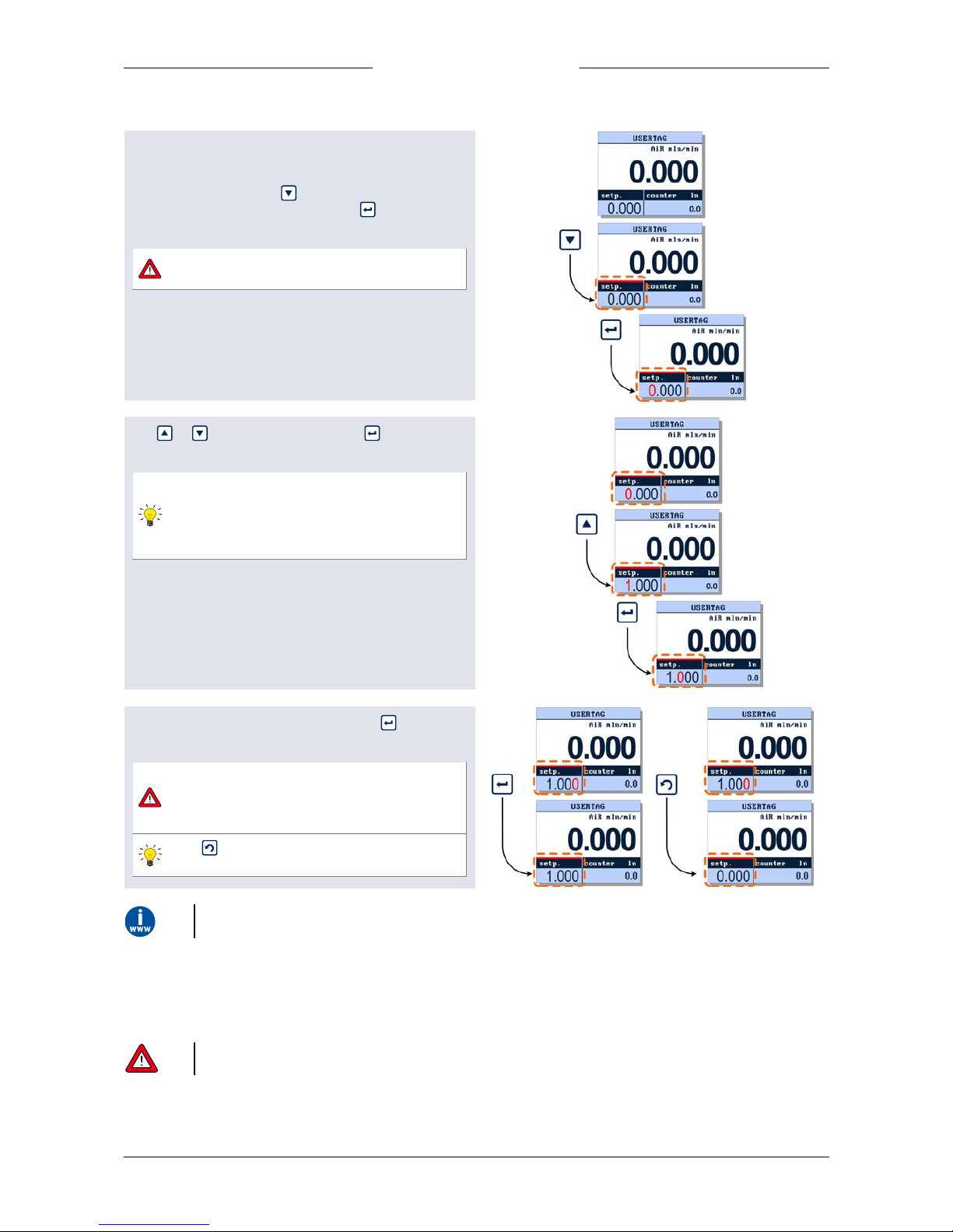
5.2.4 Temperature and flow setpoints
Setpoint can only be edited when the setpoint parameter
is displayed in 'Custom readout 1' or 'Custom readout 2'.
To edit the setpoint press to select the readout area in
which this parameter is displayed. Press to enter the
edit mode, the first digit will lighten.
Security settings can be set to avoid
unauthorised access to the setpoint parameter.
Use or to change the digits, press to conf irm
and select the next digit.
You can change the setpoint edit mode into
'step'. This enables you to change the setpoint
using fixed steps. See section 'Customize display
info' in the E-8000 manual (9.17.076) for more
detailed i nforma tion.
After the last digit is conf irmed by pressing , the
setpoint will be sent to the instrument.
If the entered setpoint is ignored, check
controller mode. See section 'Controller mode' in
the E-8000 manual (9.17.076) for more detailed
information.
The button can be used to exit the edit mode
and cancel the changes.
This chapter explains the most im portant user interface options. F or more information please check the E-8000 manual
(document no 9.1 7.076) at http://www.bronkhorst.com/en/downloads
5.3 Operational settings
Make sure that the tracing and heating temperatures are well above the dew point of the desired vapor flow at the process
conditions.
Especially for t racing, t he temperature is only controlled at a single location, while inadequate insulation may introduce
cold-spots at which condensation may occur.
Page 22
Bronkhorst®
Instruction Manual Vapor Delivery Module 9.17.079D22
Be aware that both heater and tracing temperature depend on the location of the sensor. Therefore, it is advised to set the
heater temperature approximately 20°C above the theoretical temperature.
In addition, it is advised to set the tracing temperature another 10°C higher.
5.3.1 Operation example
Application
The VDM can be used for generating certain humidity in a gas stream. Carrier gas and liquid (water) are controlled to
regulate the humidity. The water is mixed with the gas and consequently evaporated. The humidity at a certain temperature
corresponds with a certain ratio of gas and water, this r atio can be set by the flow controllers which are part of the VDM.
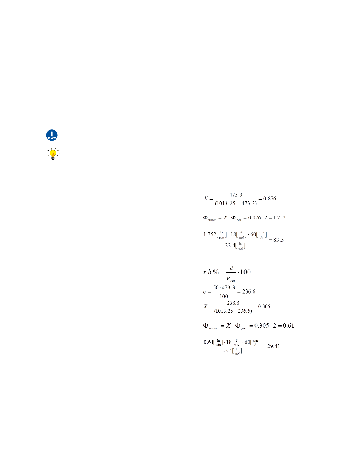
Calculation example for setting of r elative humidity
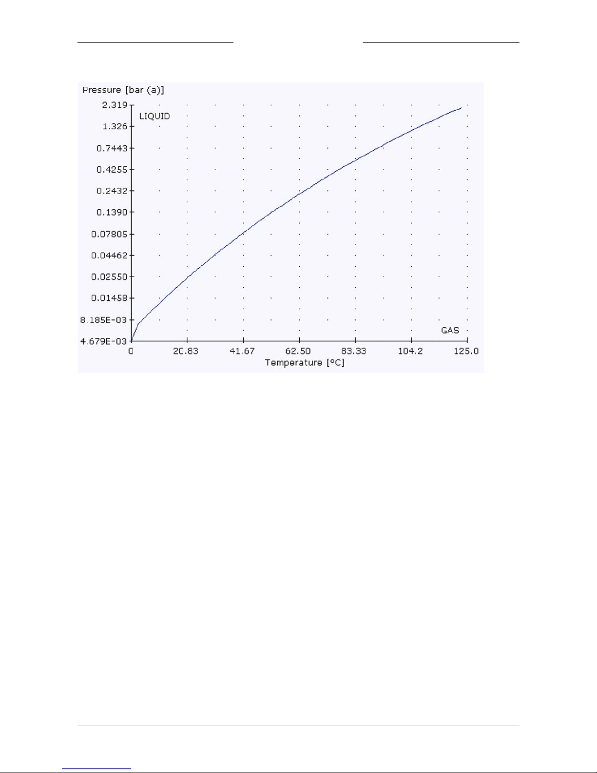
At atmospheric pressure, at 80°C, 2 ln/min Air has to be moistened. Which water flow is needed for a r.h. of 50%. The vapor
pressure of water at 80°C is 473.3 mbar according to FLUIDAT®.
FLUIDAT® on the Net: Bronkhorst's interactive F low C alculations and routines generating Physical Properties. Visit
www.fluidat.com
Assumptions:
· consider water vapor as an ideal gas
· 1 mole of ideal gas at normal conditions = 22.4 l
· 1 mole of water is 18 g and 1 hour is 60 min.
· 1 atm. = 1013. 25 mbar.
At 10 0% r.h., the (Mole)Ratio between gas and water is:
The mole ratio:
So in a gas flow of 2 ln/min, the saturated vapor flow (100% r.h.) is:
and in [g/h]:
At 50% r.h., the (Mole)Ratio between gas and water is:
The mole ratio:
So in a gas flow of 2 ln/min, the saturated vapor flow (50% r.h.) is:
and in [g/h]:
Page 23
Bronkhorst®
Instruction Manual Vapor Delivery Module9.17.079D 23
5.3.2 Vapor pressure of water
Page 24
Bronkhorst®
Instruction Manual Vapor Delivery Module 9.17.079D24
6
Troubleshooting and service
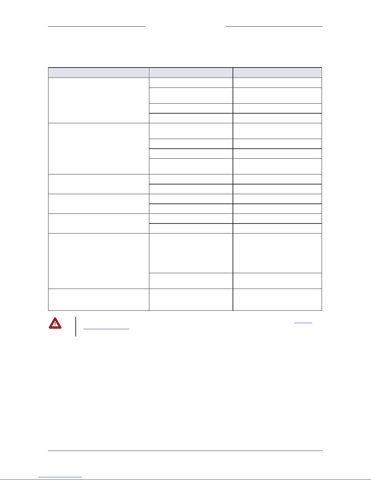
6.1 Common issues
Symptom
Possible cause
Action
No heating of heater, everything else
works
(no ready heater LED after 10 minutes)
1. Mains switch turned off
Turn on mains switch
2. Fuse may be blown
Replace fuse
(check mains and heater fuse)
3. Defective temperature sensor
Return equipment
4. Heater defective
Return equipment
No heating of tracing, everything else
works
(no ready heater LED after 30 minutes)
1. Fuse blown
Replace fuse
(check mains and tracing fuse)
2. Defective temperature sensor
Replace sensor
3. Defective tracing
Replace tracing
4. Inadequate insulation resulting
in thermal power loss
Improve insulation
No Liquid flo w
1. Wrong controller mode LFC
Check controller mode LFC
2. No setpoint
Give Setpoint
No Gas flow
1. Wrong controller mode MFC
Check controller mode MFC
2. No Setpoint
Give Setpoint
No vapor stream
1. No gas supply
Check gas supply
2. No liquid supply
Check liquid supply
Liquid in process chamber
1. Mixture saturated,
condensation
1. Increase setpoint Heater
2. Increase setpoint Tracing
3. Increase carrier gas flow
4. Decrease liquid flow
5. Any combination of the
actions 1 – 4
2. No proper insulation of the
outlet piping
Improve insulation of piping
Irregular vapor stream
Signi ficant pressure variation s
on inlets
Reduce pressure variations by e.g.
adding pressure regulators or
buffers
· In case of equipment m alfunctioning, de-installation and returning of the equipment is recommended. S ee Removal
and return instructions for relevant details.
· Do not open or disassemble the equipment.
Page 25

Bronkhorst®
Instruction Manual Vapor Delivery Module9.17.079D 25
6.2 Maintenance
Maintenance
No routine maintenance is required. In case of (other) maintenance which requires de-installation of the equipment, purge
the system first as specified in section Purging and filling
Cleaning
For cleaning the exterior use a soft damp cloth.
6.3 Service
For current information on Bronkhorst® and service addresses, please visit our website:
http://www.bronkhorst.com
Do you have any questions about our products? Our Sales Department will gladly assist you selecting the right product for
your application. Contact sales by e-mail:
For after-sales questions, our Customer Service Department is available with help and guidance.
To contact CSD by e-mail:
No matter the time zone, our experts within the Support Group are available to answer your request immediately or ensure
appropriate further action. Our experts can be reached at:
+31 859 02 1 8 66
Bronkhorst High-Tech B.V.
Nijverheidsstraat 1A
NL-7261 AK Ruurlo
The Netherlands
Page 26

Bronkhorst®
Instruction Manual Vapor Delivery Module 9.17.079D26
7
Removal and return instructions
When returning materials, always clearly describe the problem, and, if possible, the work to be done, in a covering letter.
Instrument handling:
1. Purge all fluidic lines
2. If toxic or dangerous fluids have been used, the instrument must be cleaned before shipping
3. Disconnect all external cabling and tubing and remove the instrument from the process line
4. If applicable, secure movable parts with appropriate transport safety materials, to prevent damage during
transportation
5. The instrument must be at ambient temperature bef ore packaging
6. Insert the instrument into a plastic bag and seal the bag
7. Place the bag in an appropriate shipping container; if possible, use the original packaging box
Add documentation:
· Reason of return
· Failure symptoms
· Contaminated condition
· Declaration on decontamination
It is a bsolutely requ ired to n otify the factory if toxic or dangerou s fluids have been in con tact with the device!
This is to enable the factory to take sufficient precautionary measures to safeguard the staff in their repair department.
All instruments must be dispatched with a completely filled in 'Declaration on decontamination'. Instruments without this
declaration will not be accepted.
A safety information document containing a 'D eclaration on decontamination' form (document no 9. 17.032) can be
downloaded from the Service & Sup port section of the Bronkhorst website (www.bronkhorst.com).
Important:
Clearly note, on top of the package, the customs clearance number of Bronkhorst High-Tech B.V., namely:
NL801989978B01
(only if applicable, otherwise contact your distributor for local arrangements.)
 Loading...