

Page 1
Quick Installation Guide
Doc. no.: 9.17.074D Date: 26-11-2018
Starting up the IQ+FLOW® in 10 steps
Page 2
9.17.074 D2
SCOPE OF THIS GUIDE
IQ+FLOW® Micro Fluidic Mass Flow and Pressure Meters/Controllers for gases belong to the smallest chip based instruments of
its kind. IQ+FLOW® mass flow meters/controllers can be applied for measuring and fast control of gas flows up to 5000 mln/min,
for applications with pressure conditions up to 10 bar (145 psi) and temperatures between 5 and 50 °C (41 to 122 °F). IQ+FLOW®
pressure meters/controllers can be applied for pressure ranges from 0,01…0,5 bar up to 0,2…10 bar. The instruments can either
be operated in analog or digital mode (RS232 or RS485).
This Quick Installation Guide will help you start up your IQ+FLOW® in only 10 steps, covering the following subjects:
1. Check functional properties
2. Check pressure
3. Check piping
4. Mounting/installing
5. Leak check
6. Electrical connection
7. Operational interface
8. Hardware interface
9. Purging
10. Zeroing
Other applicable documents:
· Instruction Manual for IQ+FLOW® series
9.17.045
· Instruction Manual FlowPlot
9.17.030
· Hook-up diagram IQ+FLOW® Single-channel
9.16.101
· Hook-up diagram IQ+FLOW® Multi-channel
9.16.090
These documents can be downloaded from the website: www.bronkhorst.com/downloads or can be sent by email
on request.
Starting up
1
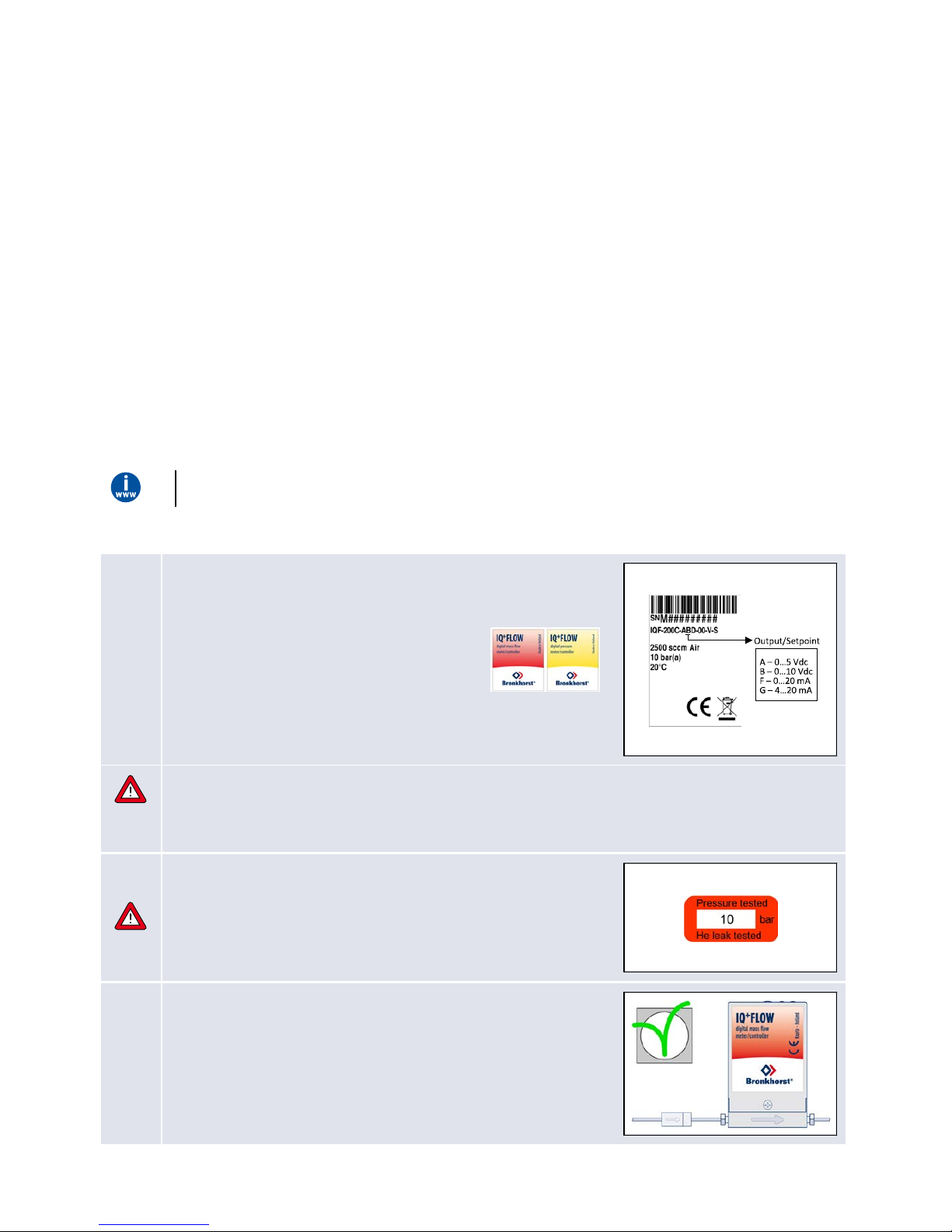
Check functional properties
Before installing the instrument, check if the properties stated on the serial
number label match your requirements:
· Instrument type
o gas flow (red label) or
o pressure (yellow label)
· Flow rate
· Fluid to be measured
· Upstream and downstream pressures
· Input/output signals
· Temperature
· IQ+FLOW® gas flow instruments are designed for dry, clean, non-corrosive gases
· IQ+FLOW® pressure instruments are designed for dry, clean, non-corrosive, non-flammable gases
Do not use the IQ+FLOW® for other gas types.
2
Check test-pressure
The tested pressure is stated on the instrument with a red label.
Before installation, make sure that the tested pressure is in accordance with
normal safety factors for your application. If a pressure test label is missing,
or if the tested pressure is insufficient, the instrument must not be
mounted in the process line and should be returned to the factory.
3
Check if system pi ping is clean
For reliable measurement, always make sure the fluid stream is clean.
Use filters to assure a moisture, oil and particle free gas stream
(recommended pore-size: 7 µm).
If back flow can occur, installing a downstream filter and a check valve is
recommended too. For high flow rates, select a suitable filter size, to avoid
a too high pressure drop.
Page 3
© 2018 Bronkhorst High-Tech B.V. 3
4
a. Mount/in stall instrument properly
· For IQ+FLOW® the upright position is preferred. When mounting an
instrument in a vertical position (flow going upward or downward),
zeroing of the instrument is advised (see step 10).
· The housing of the instrument is according to class IP40, which means
that the instrument is suitable for indoor (dry) applications, like
laboratories or well protected (OEM) housings.
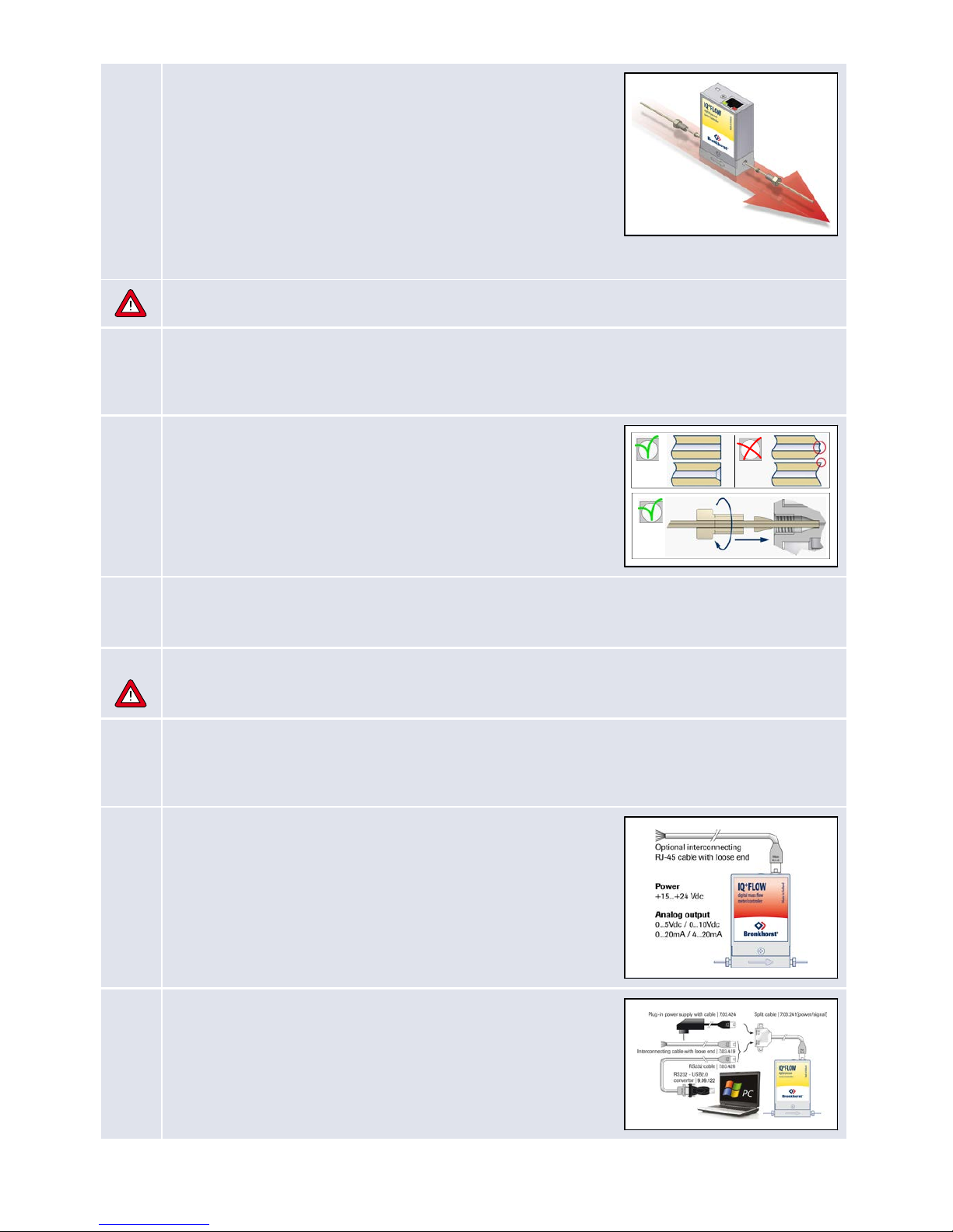
Mount the instrument in the line in accordance with the flow arrow on the instrument body. If applicable, tighten
fittings according to the instructions of their supplier. Special types of fittings are available on request.
Avoid installation in close proximity of mechanic vibration and/or heat sources.
b. Co mpression type fittings
For leak tight installation of compression type fittings make sure that the tube is inserted up to the shoulder in the
fitting body and that no dirt or dust is present on tube, ferrules or fittings. Tighten the nut finger tight; while holding
the instrument, then tighten the nut one turn.
c. 10-32 UNF fittin gs
Tighten the 10-32 UNF fittings according to the instructions of their
supplier.
Only use 1/16” tubing with a straight and clean cut without burrs to ensure
leak tightness. Preferably deburr the tubing prior to installation. A new
ferrule connection must be made for each new adapter to ensure leaktightness and minimum dead volume, due to variances in the adapter
dimensions.
d. Mounti ng do wnported instruments
For downported instruments make sure that the seals are present at the bottom, that the surfaces are undamaged
and that they are dry and free from dirt or dust.
5
Leak check
Check the fluidic system for leaks before applying pressure, especially when using hazardous media (e.g. toxic or
flammable).
6
Electrical connection
Electrical connections must be made with a standard cable or according to the IQ+FLOW® hook-up diagram. These
diagrams can be found on the “Documentation and software tools” CD-ROM and at
www.bronkhorst.com/downloads. IQ+FLOW® instruments are powered with +15…+24 Vdc.
7
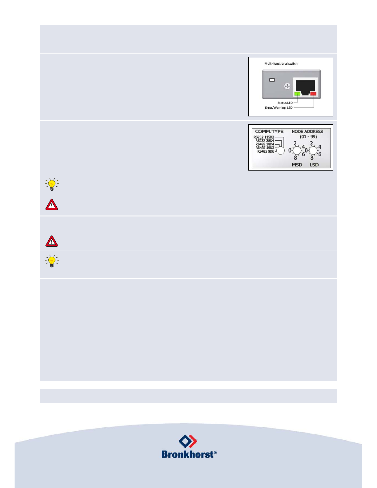
a. Analog/local operation (single-channel vers ions only)
For analog operation refer to the “Hook-up diagram IQ+FLOW®” or use an
RJ45 loose-end cable (7.03.419) to connect the required signals.
b. Digital RS232 operation
Connecting the instrument with an RS232 cable to a PC will enable you to
use the (free) Bronkhorst® software for Windows, such as FlowDDE and
FlowPlot.
See the IQ+FLOW® manual (document number 9.17.045) for further
explanation on RS232 operation of the IQ+FLOW®.
Page 4
c. Fieldbu s operation (RS485)
With digital operation over RS485 a bus-system with multiple instruments can be set up. Refer to the “Instruction
Manual IQ+FLOW® series” for possible systems.
8
a. Mul tifunctio nal micro switch operatio n (single-channel versions
only)
Using the 2 LEDs and the switch on the IQ+FLOW®, several actions can be
monitored and started. The green LED is used for status indication. The red
LED is used for error and warning messages. The switch can be used to
execute several functions, such as auto-zero and restoring factory settings.
See the IQ+FLOW® manual (document number 9.17.045) for details.
b. Ro tary swi tch operation (multi-channel version s only)
Select the communication type and Baud rate with the “COMM. TYPE”
switch. Select the node address with the “MSD” and “LSD” switch (e.g. MSD
= 1 and LSD = 9 selects node 19 for channel 1, but also node 20 and 21 for
channels 2 and 3). See section 3.3 of the Instruction Manual for more
details.
Unless specified otherwise, the IQ+FLOW® instrument is set for RS232 communication at 38k4 baud on node
address 03 by default.
Do not apply pressure until electrical connections are made. When applying pressure to the system, avoid pressure
shocks in the system and increase pressure gradually. Also decrease pressure gradually when required.
9
Purging
In systems for use with corrosive or reactive media, purging for at least 30 minutes with a dry, inert gas (like
Nitrogen or Argon) is absolutely necessary before use. After use with corrosive, reactive or hazardous media (e.g.
toxic or flammable), purging is also necessary before the system is exposed to air.
Warm-up time
For accurate measurement, it is recommended to warm up the instrument for at least 30 minutes. This can be done
with or without media flow (e.g. while purging).
10
Zeroing (only flow meters/controllers)
The zero point of each flow meter is factory adjusted. If required the zero point can be re-adjusted over RS232 or by
means of using the multifunctional switch. Procedure for zeroing by-micro switch:
· Warm up and pressurize the system and fill the instrument according to the process conditions.
· Make sure no flow is going through the instrument, by closing valves near the instrument.
· The setpoint must be zero.
· Press the multifunctional switch and hold it. After a short time, the red LED will go ON and OFF, then the green
LED will turn ON. At that moment, release the switch.
· The zeroing procedure will start at that moment and the green LED will blink fast. The zeroing procedure waits
for a stable signal and saves the zero. If the signal is not stable, zeroing will take long and the nearest point to
zero is accepted. The procedure will take approximately 10 seconds.
· When the indication is showing 0% signal and the green indication LED is glowing continuously again, then the
zeroing action was successful.
Your IQ+FLOW® is now ready for operation.
Bronkhorst High- Tech B.V., N ijverheidss traat 1a, NL-72 61AK Ru urlo, The Ne therlands
T +31( 0)57 3 45 88 00 F +31( 0)57 3 45 88 08 I www.bronkhors t.com E info@bronkhors t.com
 Loading...