

Page 1
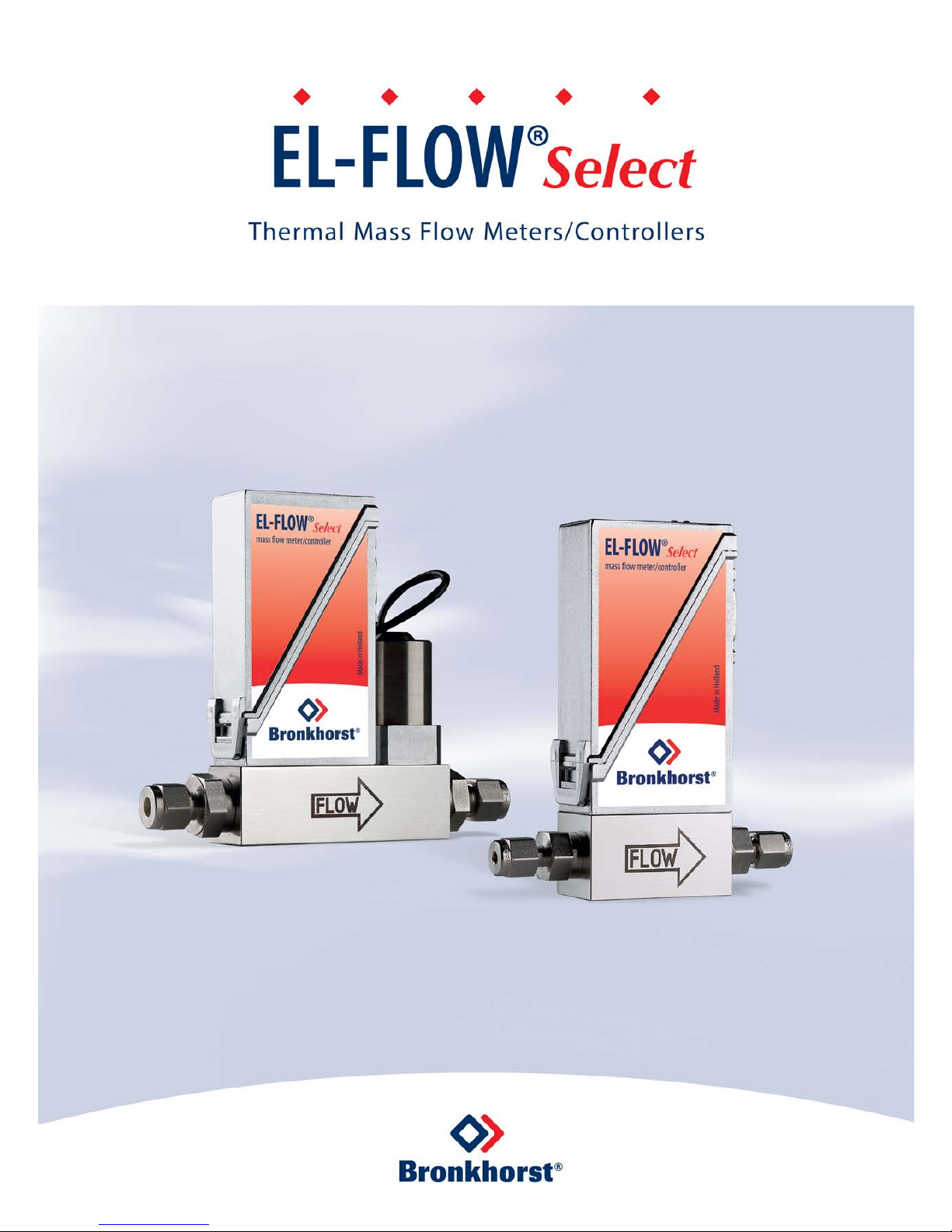
Quick Installation Guide
Doc. no.: 9.17.098A Date: 19-03-2018
Starting up EL-FLOW®Select in 10 steps
Page 2
9.17.098 A
2
SCOPE OF THIS GUIDE
This Quick Installation Guide covers the EL-FLOW® Select (including Metal Sealed) series Digital Mass Flow Meters and
Controllers for gases. These instruments are designed for laboratory and clean processing conditions and are suited to measure
and control flow ranges between 0,014…0,7 mln/min and 8…1670 ln/min, at pressures between vacuum and 400 bar.
EL-FLOW® Select instruments are equipped with a digital printed circuit board, featuring diagnostics, alarm and counter
functions, digital communication (RS232) and a PID controller. They offer great flexibility thanks to the "multibus" concept,
whereby the instruments can be equipped with an on-board fieldbus interface. The Multi Fluid / Multi Range option (to be
specified at the moment of ordering) allows the user to select flow ranges and gas types, maintaining high accuracy and
turndown ratio for measurement and control.
This Quick Installation Guide will help you start up your EL-FLOW® Select instrument in 10 steps, covering the following subjects:
1. Checking functional properties
2. Checking test pressure
3. Checking piping
4. Mounting/installing instrument
5. Leak check
6. Electrical connection
7. Analog/digital operation
8. Multifunctional switch operation
9. Purging
10. Adjusting zero point
Other applicable documents:
- Manual EL-FLOW® Select series (document no. 9.17.099)
Interfaces
Manual
Hook-up diagram
- Analog/RS232 interface
9.17.027
9.16.119
- DeviceNet™ interface
9.17.026
9.16.122
- EtherCAT® interface
9.17.063
9.16.124
- FLOW-BUS interface
9.17.024
9.16.120
- Modbus interface
9.17.035
9.16.123
- PROFIBUS DP interface
9.17.025
9.16.121
- PROFINET interface
9.17.095
9.16.148
- Custom bus & I/O configurations
n/a
9.16.118
· The instrum ent m anual a nd hook -up diag rams can be do wnloaded from the EL-FLOW® Sele ct product pages on the
Bronkhorst website : www.bronkhorst.com/products
· Other do cuments can be found on our g eneral downloa d page (www.bronkhorst.com/downloads)
Starting up
1
Check functional properties
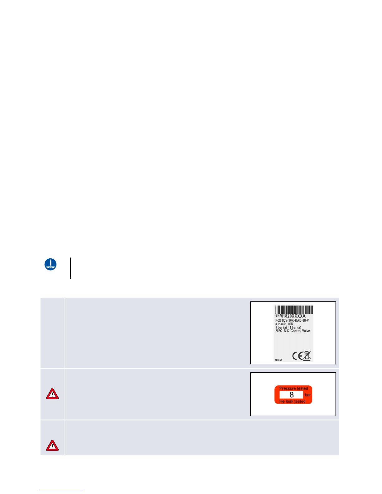
Before installing the instrument, check if the properties stated on the
instrument label match your requirements:
· Flow and/or pressure rate
· Media to be used in the instrument
· Upstream and downstream pressure(s)
· Operating temperature
· Valve type (N.C. - Normally Closed / N.O. - Normally Opened)
· Input and output signal
2a
Check test pressu re
Before installation, make sure that the test pressure is in accordance with
the safety factor of your application.
The test pressure is stated on the instrument with a red label. If this label is
missing, or if the test pressure is insufficient, the instrument must not be
mounted in the process line and should be returned to the factory.
2b
Check operating conditions
EL-FLOW® instruments are suitable for use at temperatures between -10 and +70 °C. Please note that EL-FLOW®
instruments have an ingress protection rating of IP40, implying that the electronics housing and electrical
connection do not offer any protection against moist environments.
Page 3
© 2018 Bronkhorst High-Tech B.V.
3
3
Check if system pi ping is clean
For reliable operation, always make sure the fluid stream is clean.
Use filters to ensure a moisture, oil and particle free gas stream
(recommended pore-size: 5 µm).
If back flow can occur, the use of a downstream filter and a check valve is
also recommended. Select a suitable filter size, to avoid a too high pressure
drop.
4
Mounting/installing
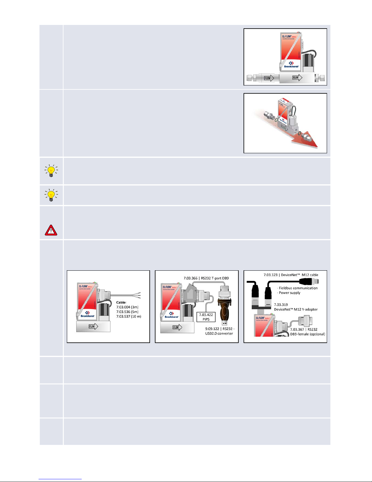
Install the instrument in the line in accordance with the flow arrow on the
instrument body. Tighten fittings according to the instructions of their
supplier. The use of Swagelok RS-type stainless steel adapters and
Bronkhorst® elastomer O-rings is recommended.
Mounting the instrument in the upright position is preferred, especially if the operating pressure will be higher than
10 bar. When mounting the instrument in a position with upward or downward flow, adjusting the zero point is
advised (see step 10).
Avoid installation in close proximity of mechanic vibration and/or heat sources.
5
Leak check
Check the system for leaks before applying (fluid) pressure, especially if toxic, explosive or other dangerous fluids
are used.
6
Electrical connection
Electrical connections must be made with standard cables or according to the applicable hook-up diagram (see
page 2): EL-FLOW® Select instruments are powered with +15…24 Vdc.
A. Analog conne ction
B. Digital RS232 connection pow ered by plug in
power supply
C. Fieldbus (e.g. Dev iceNet™)
7a
Analog/local operation
Connect the device to the power supply/readout unit using a cable with 9-pin D-sub connector. For controllers, the
setpoint is proportional to the flow range. This principle also applies to digital operation.
7b
Digital RS232 operation
Connecting the instrument with an RS232 cable to a Windows computer enables the use of the free Bronkhorst®
software for Windows, such as FlowDDE and FlowPlot.
Consult the EL-FLOW® manual (document no. 9.17.099) for further explanation on RS232 operation.
7c
Fieldbus operation
Connect the instrument according to the specific fieldbus standard. Refer to the appropriate fieldbus hook-up
document mentioned on page 2.
Page 4
8
Multifunctional switch operation
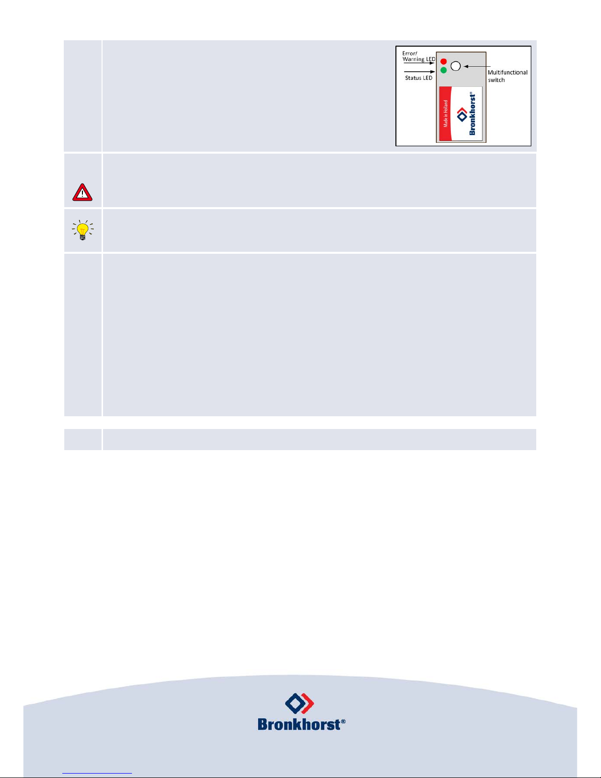
Using the 2 LEDs and the switch on the EL-FLOW®, several actions can be
monitored and started. The green LED is used for status indication. The red
LED is used for error and warning messages. The switch can be used to
execute several functions, such as zeroing, bus initialization and restoring
factory settings. Consult the EL-FLOW® manual (document no. 9.17.099)
for details.
9
Purging
If the instrument will be used with corrosive or reactive media, purging with an inert gas (e.g. Nitrogen or Argon) for
at least 30 minutes is absolutely necessary before use. After use with these media, complete purging is also
required before exposing the system to air.
Warm-up time
For accurate results, it is recommended to warm up the instrument for at least 30 minutes before starting
measurement (this can be done while purging).
10
Adju sting zero po int
The zero point of each Bronkhorst® flow meter is factory adjusted. If required, the zero point can be re-adjusted via
RS232 or with the multifunctional switch. Procedure for adjustment with the multifunctional switch:
· Warm up and pressurize the system and fill the instrument according to the actual process conditions.
· Make sure no flow is going through the instrument, by closing a valve near the instrument.
· Set the setpoint to 0%.
· Press and hold the multifunctional switch. After a short time, the red LED will turn on and off, after which the
green LED will turn on. At that moment (which is 8 seconds after pressing), release the switch.
· The zeroing procedure will start at that moment and the green LED will blink fast. The zeroing procedure waits
for a stable signal and saves the new zero point. Typically, this will take approximately 10 seconds. If the signal is
unstable, the procedure will take longer and the nearest point to zero is accepted.
· When the indication is showing 0% signal and the green indication LED is glowing continuously again, the
zeroing action was successful.
Your EL-FLOW® Select is now ready for operation.
Bronkhorst High- Tech B.V., N ijverheidss traat 1a, NL-72 61AK Ru urlo, The Ne therlands
T +31( 0)57 3 45 88 00 F +31( 0)57 3 45 88 08 I www.bronkhors t.com E info@bronkhors t.com
 Loading...