

Page 1
Doc. no.: 9.17.085D Date: 18-09-2018
ATTENTION
Please read this Instruction Manual carefully before installing and operating the instrument.
Not following the g uidelines could result in personal injury and/or damage to the equipment.
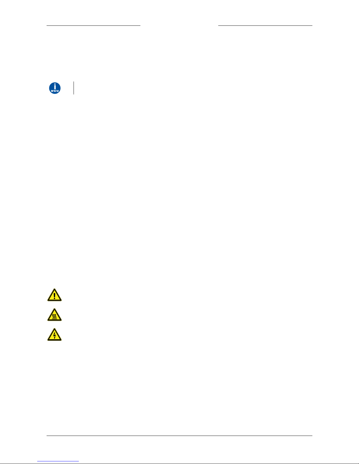
EL-FLOW® Classic series
Thermal Mass Flow Controllers
Instruction Manual
Page 2
Bronkhorst®
Instruction Manual EL-FLOW® Classic series 9.17.085D2
Disclaimer
The information in this manual has been reviewed and is believed to be wholly reliable. No responsibility, however, is
assumed for inaccuracies. The material in this manual is for information purposes only.
Copyright
© 2018 Bronkhorst High-Tech B.V.
All rights reserved. This documentation is protected by copyright.
Subject to technical and optical changes as well as printing errors. The information contained in this document is subject to
change at any time without prior notification. Bronkhorst High-Tech B.V. reserves the right to modify or improve its
products and modif y the contents without being obliged to inform any particular persons or organizations. The device
specifications and the contents of the package may deviate from what is stated in this document.
Symbols
Important information. Di sregarding this information could cause injuries to people or damage to t he instrument or
installation.
Helpful information. This information will facilitate t he use of the instrument and/or contribute to its optimal
performance.
Additional info available on the internet or from your l ocal sales representative.
Receipt of equipment
Check the outside package box for damage incurred during shipment. If the box is damaged, then the local carrier must be
notified at once regarding his liability, if so required. At the same time a report should be submitted to your local sales
representative.
Carefully remove the equipment from the box. Verify that the equipment was not damaged during shipment. Should the
equipment be damaged, then the local carrier must be notified at once regarding his liability, if so required. At the same
time a report should be submitted to your local sales representative.
Check the packing list t o ensure that you received all of the items within the scope of delivery.
Do not discard spare or replacement parts with the packaging material and inspect the contents for damage.
Refer to Removal and return instructions about return shipment procedures.
Equipment storage
The equipment should be stored in its original package in a cupboard warehouse or similar. Care should be taken not to
subject the equipment to excessive temperatures or humidity.
Page 3
Bronkhorst®
Instruction Manual EL-FLOW® Classic series9.17.085D 3
Warranty
Bronkhorst® products are warranted against defects in material and workmanship for a period of three years from the date
of shipment, provided they are used in accordance with the ordering specifications and not subject to abuse or physical
damage. Products that do not operate properly during this period may be repaired or replaced at no charge. Repairs are
normally warranted for one year or the balance of the original warranty, whichever is the longer.
See also section 9 (Guarantee) of the Conditions of sales:
www.bronkhorst.com/about/conditions-of-sales/
The warranty includes all initial and latent defects, random failures, and indeterminable internal causes.
It excludes failures and damage caused by the customer, such as contamination, improper electrical hook-up, physical shock
etc.
Re-conditioning of products primarily returned for warranty service that is partly or wholly judged non-warranty may be
charged for.
Bronkhorst High-Tech B.V. or affiliated company prepays outgoing freight charges when any part of the service is
performed under warranty, unless otherwise agreed upon beforehand, however, if the product has been returned collect to
our factory or service center, these costs are added to the repair invoice. Import and/or export charges, foreign shipping
methods/carriers are paid by the customer.
General safety precautions
This product is intended for use by qualified personnel who recognize shock hazards and are familiar with the safety
precautions required to avoid possible injury. Read the operating information carefully before using the product.
Before operating, make sure the line cord is connected to a properly grounded power receptacle. Inspect the connecting
cables for cracks or breaks before each use.
The equipment and accessories must be used in accordance with their specifications and operating instructions, otherwise
the safety of the equipment may be impaired.
If required, replace fuses with the same type and rating for continued protection against fire hazard.
Opening the equipment is not allowed. There are no repairable parts inside. In case of a defect please return the equipment
to Bronkhorst High-Tech B.V.
One or more warning signs may be present on different parts of the product. These signs have the following meaning:
Consult t he instruction manual for handling instructions
Surface may get hot during operation
Shock hazard; electrical parts i nside
To maintain protection from electric shock and fire, replacement components must be obtained from Bronkhorst. Standard
fuses, with applicable national safety approvals, may be used if the rating and type are the same. Other components that are
not safety related may be obtained from other suppliers, as long as they are equivalent to the original component. Selected
parts should be obtained only through Bronkhorst, to maintain accuracy and functionality of the product. If you are unsure
about the relevance of a replacement component, contact your local Bronkhorst representative for information.
Page 4

Bronkhorst®
Instruction Manual EL-FLOW® Classic series 9.17.085D4
Page 5

Bronkhorst®
Instruction Manual EL-FLOW® Classic series9.17.085D 5
Table of contents
. . . . . . . . . . . . . . . . . . . . . . . . . . . . . . . . . . . . . . . . . . . . . . . . . . . . . . . . . . . . . . . . . . . . . . . . . . . . . . . . . . . . . . . . . . . . . . . . . . . . . . . . . . . . 6
Introduction 1
. . . . . . . . . . . . . . . . . . . . . . . . . . . . . . . . . . . . . . . . . . . . . . . . . . . . . . . . . . . . . . . . . . . . . . . . . . . . . . . . . . . . . . . . . . . . . . . . . . . . . . . . . . . . 61.1
Scope of this manual
. . . . . . . . . . . . . . . . . . . . . . . . . . . . . . . . . . . . . . . . . . . . . . . . . . . . . . . . . . . . . . . . . . . . . . . . . . . . . . . . . . . . . . . . . . . . . . . . . . . . . . . . . . . . 61.2
Intend ed use
. . . . . . . . . . . . . . . . . . . . . . . . . . . . . . . . . . . . . . . . . . . . . . . . . . . . . . . . . . . . . . . . . . . . . . . . . . . . . . . . . . . . . . . . . . . . . . . . . . . . . . . . . . . . 61.3
Other document s
. . . . . . . . . . . . . . . . . . . . . . . . . . . . . . . . . . . . . . . . . . . . . . . . . . . . . . . . . . . . . . . . . . . . . . . . . . . . . . . . . . . . . . . . . . . . . . . . . . . . . . . . . . . . 71.4
Maintenance
. . . . . . . . . . . . . . . . . . . . . . . . . . . . . . . . . . . . . . . . . . . . . . . . . . . . . . . . . . . . . . . . . . . . . . . . . . . . . . . . . . . . . . . . . . . . . . . . . . . . . . . . . . . . 8
Starti ng up 2
. . . . . . . . . . . . . . . . . . . . . . . . . . . . . . . . . . . . . . . . . . . . . . . . . . . . . . . . . . . . . . . . . . . . . . . . . . . . . . . . . . . . . . . . . . . . . . . . . . . . . . . . . . . . 82.1
Functio nal proper ties
. . . . . . . . . . . . . . . . . . . . . . . . . . . . . . . . . . . . . . . . . . . . . . . . . . . . . . . . . . . . . . . . . . . . . . . . . . . . . . . . . . . . . . . . . . . . . . . . . . . . . . . . . . . . 82.2
Operating con dition s
. . . . . . . . . . . . . . . . . . . . . . . . . . . . . . . . . . . . . . . . . . . . . . . . . . . . . . . . . . . . . . . . . . . . . . . . . . . . . . . . . . . . . . . . . . . . . . . . . . . . . . . . . . . . 82.3
Mounting
. . . . . . . . . . . . . . . . . . . . . . . . . . . . . . . . . . . . . . . . . . . . . . . . . . . . . . . . . . . . . . . . . . . . . . . . . . . . . . . . . . . . . . . . . . . . . . . . . . . . . . . . . . . . 82.4
Fluid ic con nections
. . . . . . . . . . . . . . . . . . . . . . . . . . . . . . . . . . . . . . . . . . . . . . . . . . . . . . . . . . . . . . . . . . . . . . . . . . . . . . . . . . . . . . . . . . . . . . . . . . . . . . . . . . . . 92.5
Inlet f ilter
. . . . . . . . . . . . . . . . . . . . . . . . . . . . . . . . . . . . . . . . . . . . . . . . . . . . . . . . . . . . . . . . . . . . . . . . . . . . . . . . . . . . . . . . . . . . . . . . . . . . . . . . . . . . 92.6
Electrical connection
. . . . . . . . . . . . . . . . . . . . . . . . . . . . . . . . . . . . . . . . . . . . . . . . . . . . . . . . . . . . . . . . . . . . . . . . . . . . . . . . . . . . . . . . . . . . . . . . . . . . . . . . . . . . 9Interface 2.6.1
. . . . . . . . . . . . . . . . . . . . . . . . . . . . . . . . . . . . . . . . . . . . . . . . . . . . . . . . . . . . . . . . . . . . . . . . . . . . . . . . . . . . . . . . . . . . . . . . . . . . . . . . . . . . 9Power supp ly 2.6.2
. . . . . . . . . . . . . . . . . . . . . . . . . . . . . . . . . . . . . . . . . . . . . . . . . . . . . . . . . . . . . . . . . . . . . . . . . . . . . . . . . . . . . . . . . . . . . . . . . . . . . . . . . . . . 92.7
Powering up and powering down
. . . . . . . . . . . . . . . . . . . . . . . . . . . . . . . . . . . . . . . . . . . . . . . . . . . . . . . . . . . . . . . . . . . . . . . . . . . . . . . . . . . . . . . . . . . . . . . . . . . . . . . . . . . . 92.8
Purging befo re us e
. . . . . . . . . . . . . . . . . . . . . . . . . . . . . . . . . . . . . . . . . . . . . . . . . . . . . . . . . . . . . . . . . . . . . . . . . . . . . . . . . . . . . . . . . . . . . . . . . . . . . . . . . . . . 102.9
Zeroi ng bef ore u se
. . . . . . . . . . . . . . . . . . . . . . . . . . . . . . . . . . . . . . . . . . . . . . . . . . . . . . . . . . . . . . . . . . . . . . . . . . . . . . . . . . . . . . . . . . . . . . . . . . . . . . . . . . . . 102.10
Calibration
. . . . . . . . . . . . . . . . . . . . . . . . . . . . . . . . . . . . . . . . . . . . . . . . . . . . . . . . . . . . . . . . . . . . . . . . . . . . . . . . . . . . . . . . . . . . . . . . . . . . . . . . . . . . 112.11
Mod el key
. . . . . . . . . . . . . . . . . . . . . . . . . . . . . . . . . . . . . . . . . . . . . . . . . . . . . . . . . . . . . . . . . . . . . . . . . . . . . . . . . . . . . . . . . . . . . . . . . . . . . . . . . . . . 12
Basi c o perat ion 3
. . . . . . . . . . . . . . . . . . . . . . . . . . . . . . . . . . . . . . . . . . . . . . . . . . . . . . . . . . . . . . . . . . . . . . . . . . . . . . . . . . . . . . . . . . . . . . . . . . . . . . . . . . . . 123.1
General
. . . . . . . . . . . . . . . . . . . . . . . . . . . . . . . . . . . . . . . . . . . . . . . . . . . . . . . . . . . . . . . . . . . . . . . . . . . . . . . . . . . . . . . . . . . . . . . . . . . . . . . . . . . . 123.2
LED ind ications
. . . . . . . . . . . . . . . . . . . . . . . . . . . . . . . . . . . . . . . . . . . . . . . . . . . . . . . . . . . . . . . . . . . . . . . . . . . . . . . . . . . . . . . . . . . . . . . . . . . . . . . . . . . . 133.3
Multi functio nal switch
. . . . . . . . . . . . . . . . . . . . . . . . . . . . . . . . . . . . . . . . . . . . . . . . . . . . . . . . . . . . . . . . . . . . . . . . . . . . . . . . . . . . . . . . . . . . . . . . . . . . . . . . . . . . 13Normal operating function s 3.3.1
. . . . . . . . . . . . . . . . . . . . . . . . . . . . . . . . . . . . . . . . . . . . . . . . . . . . . . . . . . . . . . . . . . . . . . . . . . . . . . . . . . . . . . . . . . . . . . . . . . . . . . . . . . . . 13Power-up f unction s 3.3.2
. . . . . . . . . . . . . . . . . . . . . . . . . . . . . . . . . . . . . . . . . . . . . . . . . . . . . . . . . . . . . . . . . . . . . . . . . . . . . . . . . . . . . . . . . . . . . . . . . . . . . . . . . . . . 14
Adva nced oper atio n 4
. . . . . . . . . . . . . . . . . . . . . . . . . . . . . . . . . . . . . . . . . . . . . . . . . . . . . . . . . . . . . . . . . . . . . . . . . . . . . . . . . . . . . . . . . . . . . . . . . . . . . . . . . . . . 144.1
Using other gases than specified
. . . . . . . . . . . . . . . . . . . . . . . . . . . . . . . . . . . . . . . . . . . . . . . . . . . . . . . . . . . . . . . . . . . . . . . . . . . . . . . . . . . . . . . . . . . . . . . . . . . . . . . . . . . . 144.2
Conversion factor calculation
. . . . . . . . . . . . . . . . . . . . . . . . . . . . . . . . . . . . . . . . . . . . . . . . . . . . . . . . . . . . . . . . . . . . . . . . . . . . . . . . . . . . . . . . . . . . . . . . . . . . . . . . . . . . 144.3
Maximum pressure drop
. . . . . . . . . . . . . . . . . . . . . . . . . . . . . . . . . . . . . . . . . . . . . . . . . . . . . . . . . . . . . . . . . . . . . . . . . . . . . . . . . . . . . . . . . . . . . . . . . . . . . . . . . . . . 15
Troub lesho oti ng and service 5
. . . . . . . . . . . . . . . . . . . . . . . . . . . . . . . . . . . . . . . . . . . . . . . . . . . . . . . . . . . . . . . . . . . . . . . . . . . . . . . . . . . . . . . . . . . . . . . . . . . . . . . . . . . . 155.1
Errors
. . . . . . . . . . . . . . . . . . . . . . . . . . . . . . . . . . . . . . . . . . . . . . . . . . . . . . . . . . . . . . . . . . . . . . . . . . . . . . . . . . . . . . . . . . . . . . . . . . . . . . . . . . . . 155.2
Common issues
. . . . . . . . . . . . . . . . . . . . . . . . . . . . . . . . . . . . . . . . . . . . . . . . . . . . . . . . . . . . . . . . . . . . . . . . . . . . . . . . . . . . . . . . . . . . . . . . . . . . . . . . . . . . 175.3
Service
. . . . . . . . . . . . . . . . . . . . . . . . . . . . . . . . . . . . . . . . . . . . . . . . . . . . . . . . . . . . . . . . . . . . . . . . . . . . . . . . . . . . . . . . . . . . . . . . . . . . . . . . . . . . 18
Returns 6
. . . . . . . . . . . . . . . . . . . . . . . . . . . . . . . . . . . . . . . . . . . . . . . . . . . . . . . . . . . . . . . . . . . . . . . . . . . . . . . . . . . . . . . . . . . . . . . . . . . . . . . . . . . . 186.1
Removal and retu rn instructions
. . . . . . . . . . . . . . . . . . . . . . . . . . . . . . . . . . . . . . . . . . . . . . . . . . . . . . . . . . . . . . . . . . . . . . . . . . . . . . . . . . . . . . . . . . . . . . . . . . . . . . . . . . . . 186.2
Disposal (end of lifetime)
Page 6
Bronkhorst®
Instruction Manual EL-FLOW® Classic series 9.17.085D6
1
Introduction
1.1 Scope of this manual
This user guide describes the EL-FLOW® Classic series mass flow controllers for gases. It covers product information,
installation instructions, operation, maintenance, troubleshooting tips and technical specifications.
1.2 Intended use
EL-FLOW® Classic instruments were designed to measure an/or control gas flow rates of the specified gas as stated on the
instrument label. The gas must be clean and dry. The instruments can be used for either (fast) switching or controlling a
constant flow rate.
The end user i s considered to be familiar with the necessary safety precautions, and to comply with the appropriate
protective measures as described in the Material S afety Data Sheets of the media to be used in the system (if applicable).
The wetted materials incorporated in t he EL-FLOW® Classic are compatible with media and conditions (e.g. pressure,
temperature) as specified at ordering tim e. If you are planning to use the product (including any third party components
supplied by Bronkhorst, such as pumps or valves) with other media and/or other conditions, always be sure to check the
wetted materials (including seals) for compatibility. See the technical specifications of the product and consult t hird party
documentation (if applicable) to check the incorporated materials.
Responsibility for the use of the equipment with regard to suitability, intended use, cleaning and corrosion resistance of the
used materials against the applied media lies solely with the end user. Bronkhorst High-Tech B.V. cannot be held liable for
any damage resulting from im proper use, use for other than the intended purpose or use with other media and/or under
other conditions than specified on the purchase order.
1.3 Other documents
Basic instructions
Technical drawings
Quick installation guide EL-FLOW® Classic
Document no. 9.17.086
Hook-up diagram EL-FLOW® Classic
Document no. 9.16.117
Dimensional drawing F-201 CL
Document 7.15.182
These documents can be found at http://www.bronkhorst.com/en/qrclassic
Page 7

Bronkhorst®
Instruction Manual EL-FLOW® Classic series9.17.085D 7
1.4 Maintenance
No regular maintenance is required if the EL-FLOW® Classic is operated properly, with clean media, compatible with the
wetted materials, avoiding pressure and thermal shocks and vibrations. Units may be purged with a clean, dry and inert gas.
In case of severe contamination, cleaning the inside of the device may be required. After cleaning, recalibration of the
instrument is recommended.
Inexpertly servicing instruments can lead to serious personal injury and/or damage to the instrument or the system it is
used in. T herefore, servicing must be performed by trained and qualified personnel. Contact your local Bronkhorst
representative for information about cleaning and calibration. Bronkhorst has a trained staff available.
Page 8
Bronkhorst®
Instruction Manual EL-FLOW® Classic series 9.17.085D8
2
Starting up
2.1 Functional properties
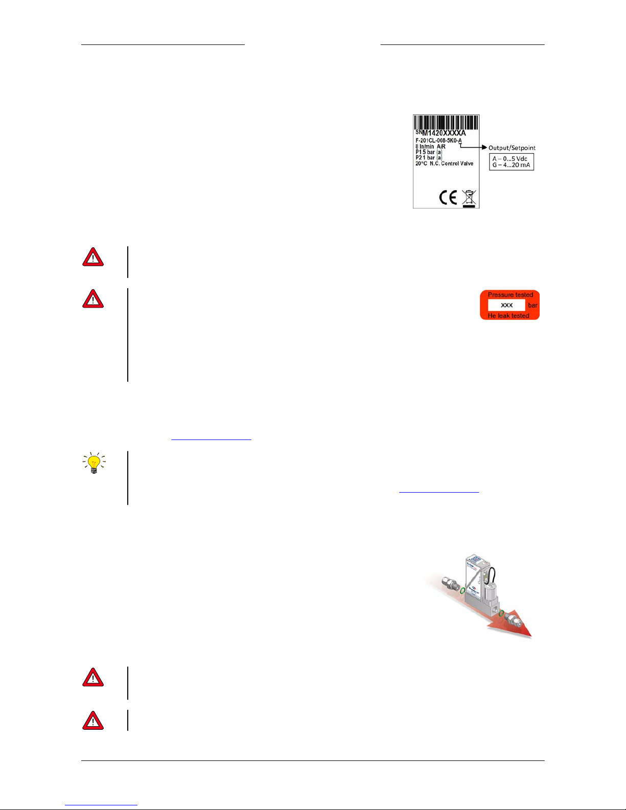
Before installing the EL-FLOW® Classic, check the serial number label to see if the
functional properties match your requirements:
· Flow rate
· Media to be used in the instrument
· Input and output signal
· Upstream and downstream pressure(s)
· Operating temperature
2.2 Operating conditions
The EL-FLOW® Classic is fitt ed with Viton® seals. Be sure that the sealing material is compatible with the media and
conditions used in the system. Bronkhorst High-Tech B.V. cannot be held responsible for any damage resulting from the use
of other media and/or conditions than specified on the purchase order.
Bronkhorst® i nstruments are pressure tested to at least 1. 5 times the requested maximum allowed
operating pressure (30 bar(g)) and outboard leak tested to at l east 2 * 10-9 mbar l /s Helium. The tested
pressure is specified on the instrument with a r ed sticker. If this sticker is mi ssing or if the specified
pressure is i nsufficient, the instrument m ust not be used and should be returned to the factory.
Before installation, make sure that the tested pressure is in accordance with the safety factor of your application. The tested
pressure must always be higher than the maximum operating pressure.
Disassembling the instrument and/or replacing parts of it will invalidate the pressure test specification.
2.3 Mounting
The bottom side of the EL-FLOW® Classic is fitted with two threaded mounting holes for stable mechanical fixation of the
instru ment. Refer to the dimensional drawing for the exact position of the mounting holes.
For optim al performance, observe the following guidelines:
· Preferably, mount the EL-F LOW® Classic in an upright position, especially i f the operating pressure is higher than 10 bar
· When mounting the instrument i n a position with upward or downward flow, adjusting the zero point is r ecommended
· Avoid installation in close proximity of mechanical vibration and/or heat sources
2.4 Fluidic connections
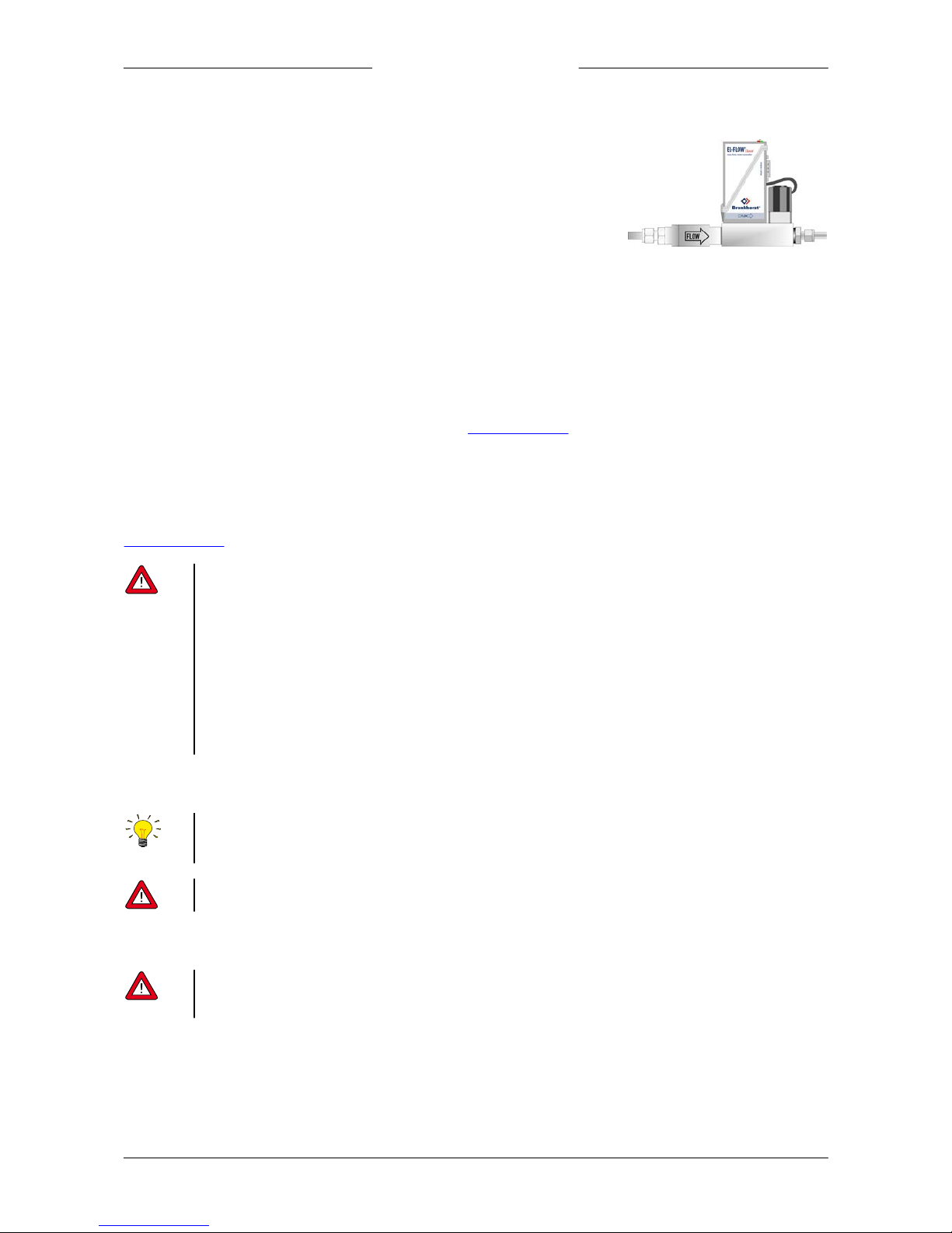
· Install the EL-FLOW® Classic in the process line, in accordance with the direction of
the FLOW arrow on the product label.
· The fluidic connections are provided with a ¼” BSPP female thread. The adapter
chambers are optimized for the use of Swagelok® RS-type adapters combined with
AS013 (70°Sh) O-rings for leak tight installation.
· Tighten connections according to the instructions of the supplier of the fittings. The
use of Swagelok® RS-type stainless steel adapters is recommended (part no. SS-4001-4RS). Adapters can be ordered separately. Contact your local distributor for more
information.
· Do not install small diameter piping on high flow rates and avoid abrupt angles or other disturbances within a distance
of 10 pipe diameters from the inlet or outlet of the device.
· Do not install pressure regulators within a distance of 25 pipe diameters.
Check the fluidic system for l eaks before applying pressure, especially if toxic, explosive or other dangerous fluids are used.
Page 9
Bronkhorst®
Instruction Manual EL-FLOW® Classic series9.17.085D 9
2.5 Inlet filter
Fluids to be measured should be absolutely free of dirt, oil, moisture and other
particles. Fluids that are heavily contaminated or contain particulates are detrimental
to precision. If liquid phases enter the sensor chamber, the function of the sensor and
the mass flow controller may be impaired. It is recommended to install an in-line filter
(offered by Bronkhorst) or liquid separator upstream of the flow controller, and if
backflow can occur, a downstream filter is recommended too. Be aware of the pressure
drop caused by the filter(s). Contact your distributor for further information.
2.6 Electrical connection
2.6.1 Interface
EL-FLOW® Classic instruments are analog operated, I/O signals can be provided by means of:
1. Voltage I/O (0...5Vdc)
2. Current I/O (4...20mA sourcing)
For electrical hook-up diagram refer to the EL-FLOW® Classic hook-up diagram.
2.6.2 Power supply
EL-FLOW® Classic controllers are powered with +15 Vdc to +24 Vdc.
When providing your own power supply be sure that voltage and current rating are according to the specifications of the
instrument(s) and that the source is capable of delivering enough power to the instrument(s). Refer to the EL-FLOW® Classic
hook-up diagram, for more details.
The device contains electronic components that are susceptible to damage by electrostatic discharge. Proper handling
procedures must be followed during installation, (dis)connecting and removing the electronics.
The device described in this manual carries the CE -mark and is compliant with th e concerning EMC requirements.
However, compliance with the EMC requirements is not possible without the use of proper cables and connector/gland
assemblies. Bronkhorst recommends the use of their standard cables. T hese cables have the right connectors and if loose
ends are used, these are marked to help prevent wrong connection. When using other cables, cable wire diameters should
be sufficient to carr y the supply current, and voltage loss must be kept as low as possible. When in doubt, contact your local
Bronkhorst representative.
When connecting the product t o other devices, be sure that the integrity of the shielding is not affected; a lways use
shielded cabling for signa ls an d commu nication and do not use u nshielded wire terminals.
2.7 Powering up and powering down
· It i s recommended to turn on power before applying pressure and to switch off power after removing pressure.
· For best performance, allow the device to warm up and stabilize for at least 30 m inutes before starting measurement
and/or control. This may be done with or without media flow.
Be sure to apply the specified operating pressure(s). Avoid pressure shocks and bring the fluidic system gradually up to the
level of operating conditions; open and close the fluid supply gently.
2.8 Purging before use
In systems for use with corrosive, reactive or explosive media, purging the fluidic lines of the device for at least 30 minutes
with a dry, i nert gas (like Nitrogen or Argon) is absolutely necessary before use. After use with these media, complete
purging is also required before exposing the system to air.
Page 10
Bronkhorst®
Instruction Manual EL-FLOW® Classic series 9.17.085D10
2.9 Zeroing before use
The zero-point of each instrument is factory adjusted at approximately 20 °C and atmospheric pressure. If the operating
conditions differ significantly f rom the ambient conditions used for factory adjustment, the zero point may need to be readjusted.
Procedure for zeroing with the multif unctional switch on top of the instrument:
· Warm-up the instrument, pressurize the system and fill the instrument according to the process conditions.
· Make sure no flow is going through the instrument by closing valves near the instrument.
· The setpoint must be zero.
· Press and hold the multifunctional switch. After a short time the red LED will go ON and OFF, then the green LED will go
ON. At that moment release the switch.
· The zeroing procedure will start at that moment and the green LED will blink fast. The zeroing procedure waits for a
stable signal and saves the zero. If the signal is not stable, zeroing might take longer and the nearest point to zero is
accepted. The procedure will take approximately 10 seconds.
· When the indication is showing 0% signal and the green indication LED is glowing continuously again, then the zeroing
action was successful.
2.10 Calibration
EL-FLOW® Classic instruments are Air or N2 calibrated. Bronkhorst High-Tech B.V. certifies that all instruments meet the rated
accuracy. They have been calibrated using measurement standards traceable to the standards of the Dutch Metrology
Institute (VSL).
The calibration is converted to the customer’s gas and conditions using a detailed conversion model. This conversion adds
a level of calibration uncertainty.
Rule of thumb for calculating the conversion uncertainty:
Uncertainty < 2% x CF for CF > 1
Uncertainty < 2% / CF for CF < 1
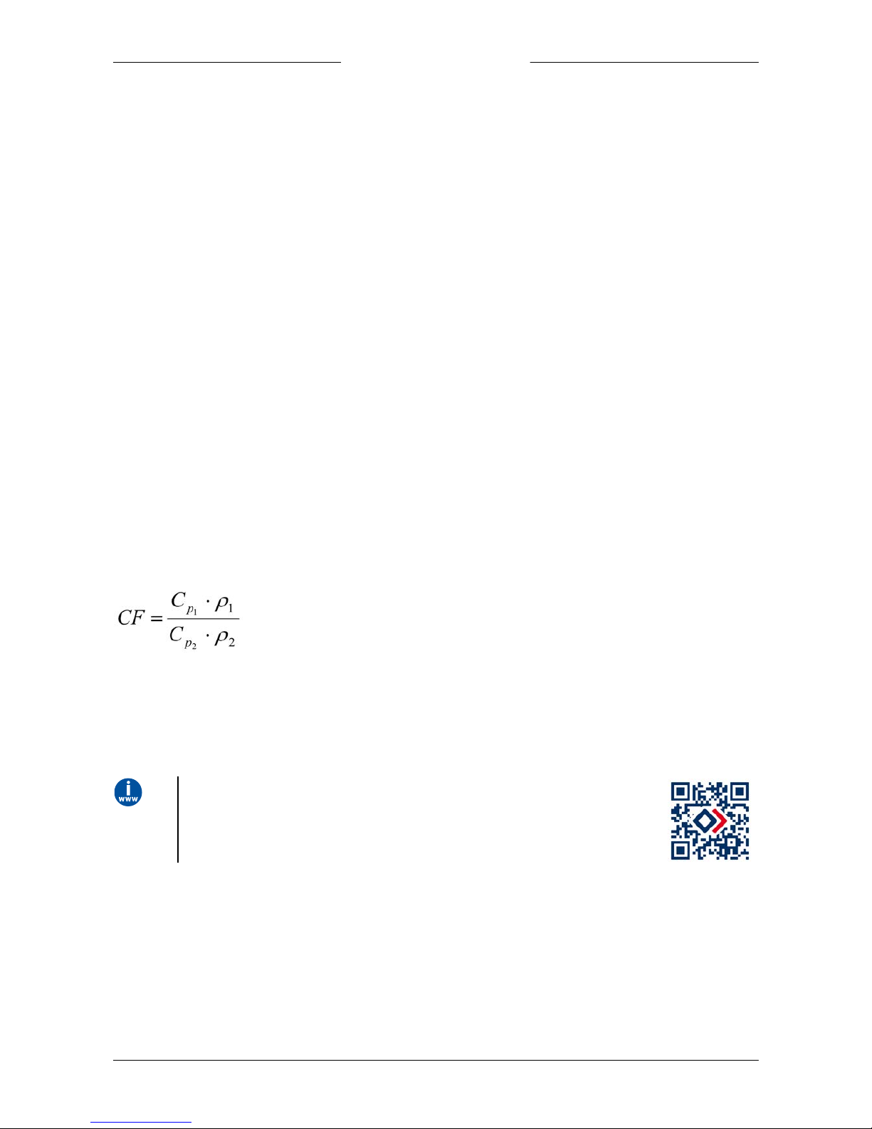
With CF defined as the approximate conversion factor, which can be calculated with:
in which: C
pn
specific heat
r
n
density at normal conditions
(1) calibration fluid (Air or N2)
(2) customer fluid
EL-FLOW® Classic instruments are delivered with a statement of compliance. T his
document can be found at http://www.bronkhorst.com/en/qrclassic.
Use the hyperlink above or scan the QR-code on the right or on top of the instrument.
Page 11
Bronkhorst®
Instruction Manual EL-FLOW® Classic series9.17.085D 11
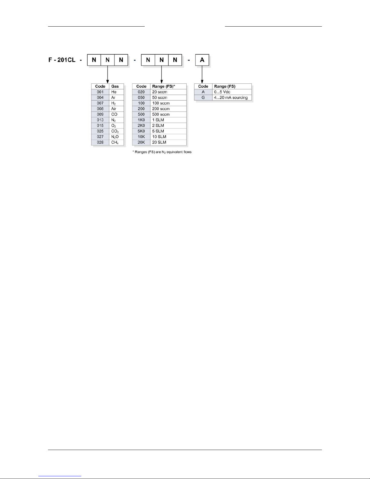
2.11 Model key
Example: F-2 01CL-009 -1K0-A
Gas
CO
Range
1 SLM
Analog output
0…5 Vdc
Page 12

Bronkhorst®
Instruction Manual EL-FLOW® Classic series 9.17.085D12
3
Basic operation
3.1 General
The following signals are available:
· input: setpoint
· output: measured value
The interface type of the instrument (0…5V or 4…20mA) can be found in the model key stated on the serial number label.
Input signa ls:
Setpoints below 2% of the full scale will be interpreted as 0% setpoint.
Output sign als:
The 100% point of the measured value is based on the flow rate requested at ordering time. This flow rate can be found on
the serial number label.
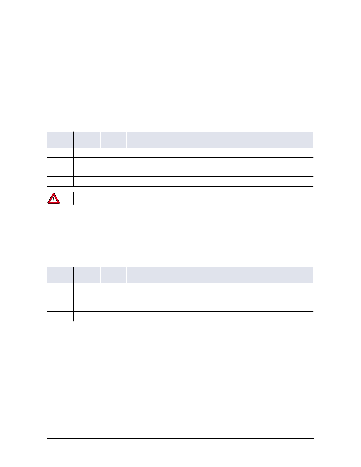
3.2 LED indications
•
(green) Mode: operation mode indication
(red) Error: error/warning messages
The tables below list the different LED indications:
•
Green
Pattern
Time
Indication
on
continuous
Normal operation mode
off
continuous
Power off or program not running
blink
0.2 sec on,
0.2 sec off
Special function mode; the instrument is busy performing a special function (e.g.
auto-zero or self-test)
•
Red
Pattern
Time
Indication
on
continuous
Critical error; the instrument needs servicing before it can be used
•
Green and • red ( alternating)
Pattern
Time
Indication
fast wink
0.1 sec on,
0.1 sec off
Selected action started (after releasing the multifunctional switch)
Page 13
Bronkhorst®
Instruction Manual EL-FLOW® Classic series9.17.085D 13
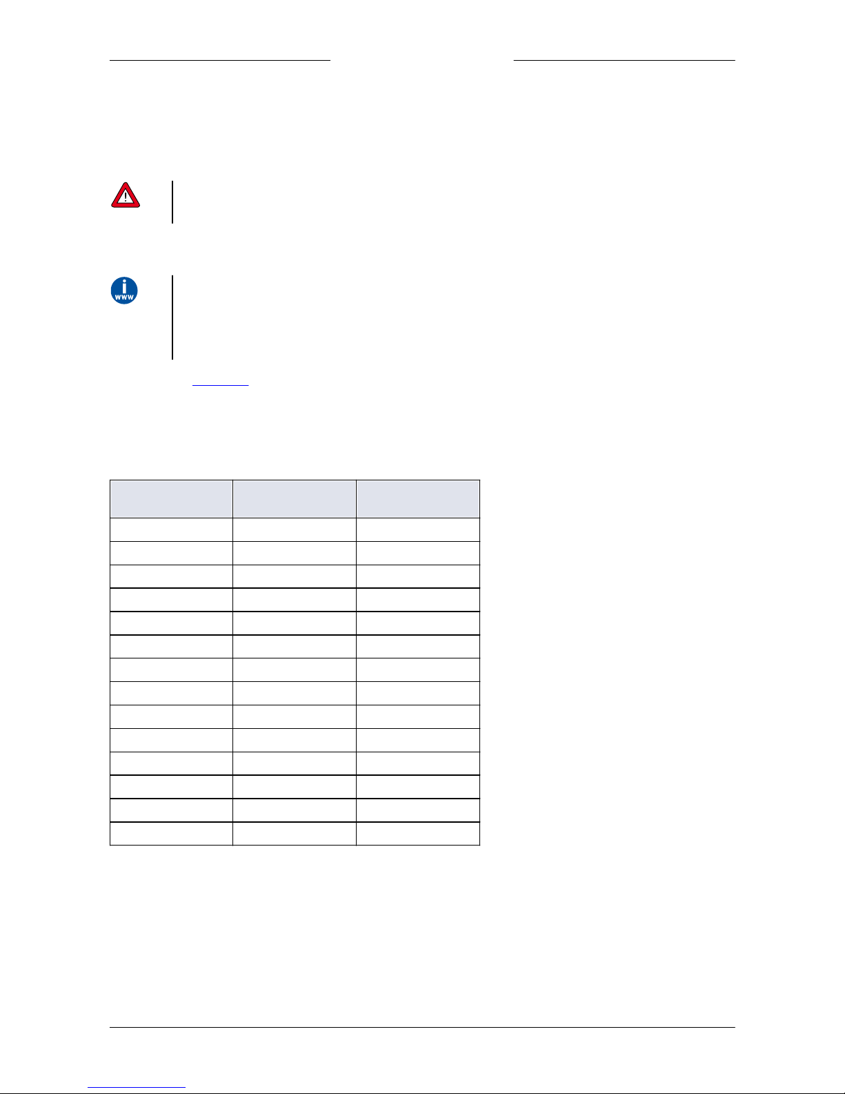
3.3 Multifunctional switch
Some special functions of the instrument can be started manually using the multifunctional switch near the indication
LEDs.
3.3.1 Normal operating functions
· In order to access these functions, press and hold the switch while the instrument is in normal operation mode (green
LED glowing).
· As long as the switch is held, the LEDs show a repeating sequence of patterns, where each pattern indicates a function.
· All indications in this sequence are continuous.
· Each pattern is shown for a number of seconds; in the table below the column Hold tim e indicates the time frame within
the sequence where the LEDs show the associated pattern.
· To start a function, release the switch when the LEDs show the pattern of the required function.
•
(green)
•
(red)
Hold time
Function
off
off
0…4 sec
No action
off
on
4…8 sec
Reset instrument; clear all warnings and error messages and restart the instrument
on
off
8…12 sec
Auto-zero; re-adjust the zero-point of the instrument (flow meters/controllers)
on
on
12…16 sec
Factory mode, do not use
See Zeroing before use for background information and instructions on how to adjust the zero point of an instrument.
Never perform a zeroing procedure before having taken notice of the instructions.
3.3.2 Power-up functions
· In order to access these functions, press and hold the switch while powering up the instrument.
· As long as the switch is held, the LEDs show a repeating sequence of patterns, where each pattern indicates a function.
· All indications in this sequence are flashing (0.2 sec on, 0.2 sec off).
· Each pattern is shown for a number of seconds; in the table below the column Hold tim e indicates the time frame within
the sequence where the LEDs show the associated pattern.
· To start a function, release the switch when the LEDs show the pattern of the required function.
•
(green)
•
(red)
Hold time
Function
off
off
0…4 sec
No action
off
on
4…8 sec
Restore factory settings (All parameter settings will be restored)
on
off
8…12 sec
No action
on
on
12…16 sec
Factory mode, do not use
Page 14
Bronkhorst®
Instruction Manual EL-FLOW® Classic series 9.17.085D14
4
Advanced operation
4.1 Using other gases than specified
Each instrument has been calibrated and adjusted f or customer process conditions.
Controllers or valves may not operate correctly, if process conditions vary too much, because of the restricti on of the orifice
in the valve. T he performance and accuracy of thermal Mass Flow Controllers may be affected tremendously if physical
fluid properties such as heat capacity and viscosity change due to changing process conditions.
4.2 Conversion factor calculation
Bronkhorst has gathered the physical properties of over 600 fluids in a database called FLUIDAT® This database also
provides a collection of routines to calculate physical properties of gases and liquids, not only at 20° C/1 atm but at any
temperature/pressure combination, both for gases and for liquids.
Check F LUIDAT ® on the N et on http://www.fluidat.com
Consult your distributor for m ore details.
Also see s ection Calibration.
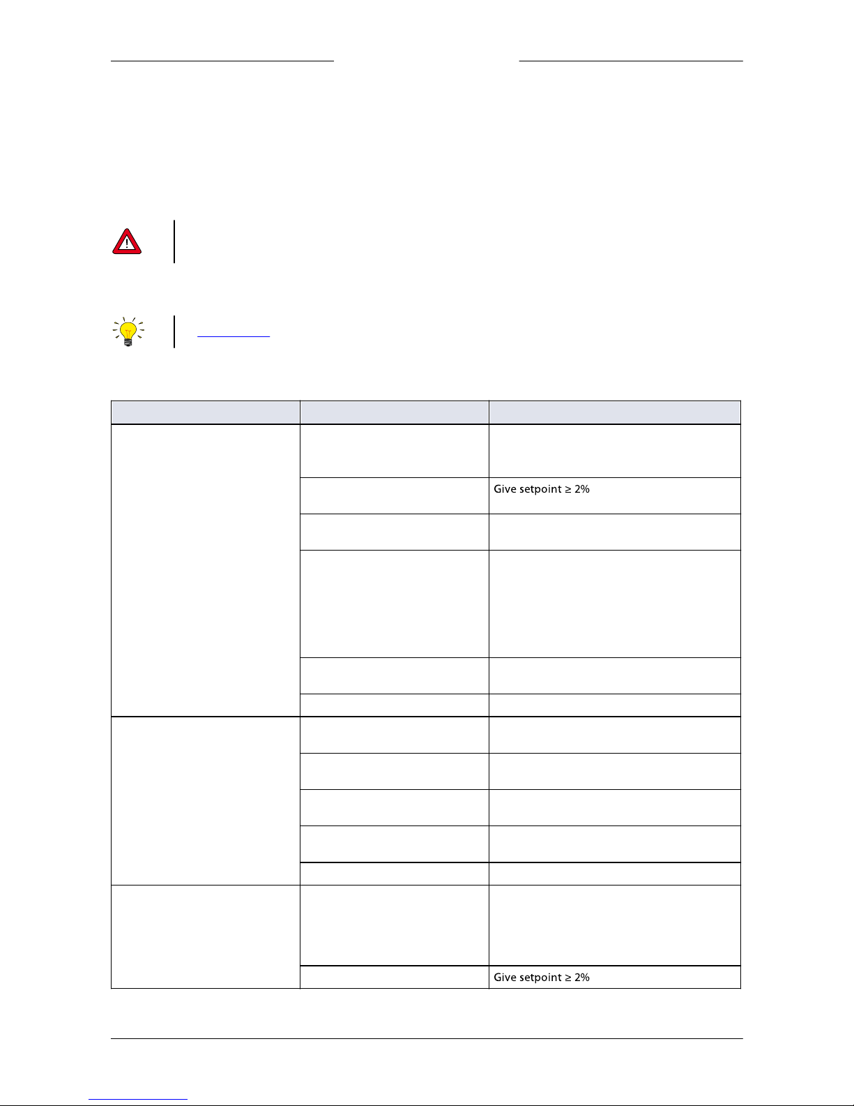
4.3 Maximum pressure drop
For (pilot) solenoid operated control valves with small orifices, the maximum allowable pressure drop for gases is according
to the table.
Diameter [mm]
Kv
Normally closed
Dp max. [bard]
0,05
4,33 x 10
-5
30
0,07
8,48 x 10
-5
30
0,10
1,73 x 10
-4
30
0,14
3,39 x 10
-4
30
0,20
6,93 x 10
-4
30
0,30
1,56 x 10
-3
30
0,37
2,37 x 10
-3
30
0,50
4,33 x 10
-3
30
0,70
8,48 x 10
-3
24
1,00
1,73 x 10
-2
12
1,30
2,93 x 10
-2
8
1,50
3,90 x 10
-2
6
1,70
5,00 x 10
-2
5
2,00
6,63 x 10
-2
3,6
Page 15
Bronkhorst®
Instruction Manual EL-FLOW® Classic series9.17.085D 15
5
Troubleshooting and service
For a correct analysis of the proper operation of a flow meter/controller it is recommended to remove the unit from the
process line and check it without applying fluid supply pressure. In case the unit is dirty, this can be ascertained
immediately by loosening the compression type couplings on the inlet side.
Energizing and de-energizing the instrument can indicate if there is an electronic failure. After energizing, control behavior
can be checked by applying fluid pressure.
If you suspect leakage, do not check for gas bubbles with a l eak detection liquid under the cover, as this may short-circuit
the sensor or t he printed circuit board.
Do not disassemble the instrument for inspection, but contact your local distributor for service or repairs.
5.1 Errors
See LED indications for an explanation of the LED indications the instrument can give.
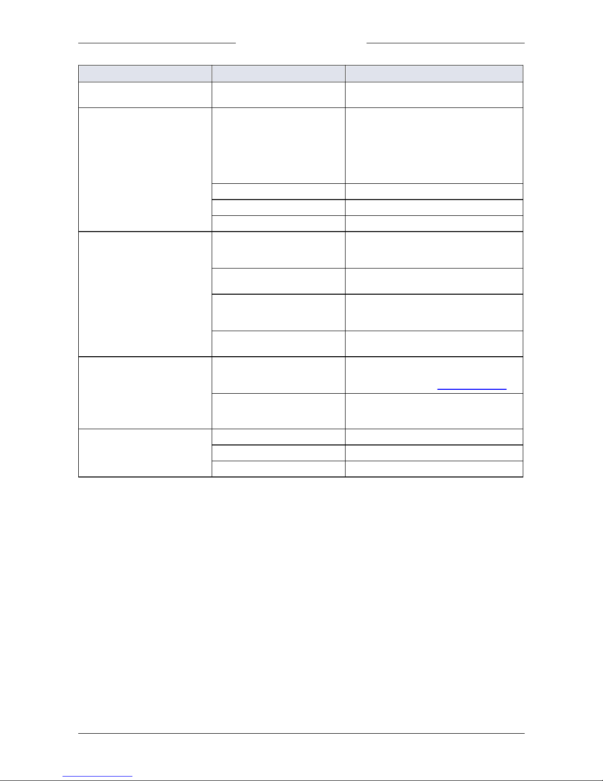
5.2 Common issues
Symptom
Possible cause
Action
No output signal
No power supply
· Check power supply
· Check cable connection
· Check cable hook-up
No setpoint given or setpoint too
low
Inlet pressure or differential
pressure too low
Increase inlet pressure
Piping, filters and/or control valve
clogged or blocked
· Flush fluidic system with clean, dry air. If
problem persists, contact Bronkhorst.
· For external proportional control valves:
supply 0…15 Vdc and operational inlet
pressure to valve and slowly increase
voltage. If valve does not open, clean parts
and re-adjust valve
Laminar flow element clogged or
blocked
Return equipment to factory
Sensor failure
Return equipment to factory
Control behavior unstable
Measurement disturbed by
vibrations
If possible, avoid installation in close proximity
of mechanical vibration
Inlet pressure unstable
Install pressure regulator or increase buffer
volume between controlling instruments
Inlet and/or outlet pressure too
high or too low
Adjust pressure and/or set instrument pressure
in accordance with actual process pressure
Wrong process fluid supplied
Supply instrument with fluid it was configured
for
Control valve damaged
Return equipment to factory
No flow (sending a setpoint has no
effect)
No fluid supply
Check upstream components for obstruction,
e.g.:
· fluidic lines
· valves
· filters
Setpoint too low
Page 16
Bronkhorst®
Instruction Manual EL-FLOW® Classic series 9.17.085D16
Symptom
Possible cause
Action
Inlet pressure or differential
pressure out of bounds
Set inlet pressure to a value within
specifications
Measured value rises, but never
reaches setpoint
Piping, filters and/or control valve
clogged or blocked
· Flush fluidic system with clean, dry air. If
problem persists, contact Bronkhorst.
· For external proportional control valves:
supply 0…15 Vdc and operational inlet
pressure to valve and slowly increase
voltage. If valve does not open, clean parts
and re-adjust valve
Inlet pressure too low
Increase inlet pressure
Outlet pressure too high
Check/decrease outlet pressure
Process outlet blocked
Check process outlet and downstream piping
Measured value or output signal
(much) lower than setpoint
Inlet pressure or differential
pressure too low
· Increase inlet pressure
· Use instrument in conditions it was designed
for
Process gas condensation
Decrease inlet pressure or increase gas
temperature
· Piping, filters and/or control
valve clogged or blocked
· Sensor blocked or contaminated
Flush fluidic system with clean, dry air. If
problem persists, contact Bronkhorst.
Supplied fluid type does not match
configured fluid type
Supply instrument with fluid it was configured
for
Measured value or output signal
indicates a flow, while there is
none
Mounting orientation and/or
ambient conditions changed
significantly
· Use instrument in conditions it was designed
for
· Adjust zero point (see Zeroing before use)
System leakage
Check the fluidic system for leakage. Follow
vendor instructions when installing third party
components (e.g. adapters, tubing, valves)
Continuous maximum measured
value or output signal
Inlet pressure too high
Check inlet pressure
Valve fully open
Close valve
Sensor failure
Return equipment to factory
Page 17

Bronkhorst®
Instruction Manual EL-FLOW® Classic series9.17.085D 17
5.3 Service
For current information on Bronkhorst® and service addresses, please visit our website:
http://www.bronkhorst.com
Do you have any questions about our products? Our Sales Department will gladly assist you selecting the right product for
your application. Contact sales by e-mail:
For after-sales questions, our Customer Service Department is available with help and guidance.
To contact CSD by e-mail:
No matter the time zone, our experts within the Support Group are available to answer your request immediately or ensure
appropriate further action. Our experts can be reached at:
+31 859 02 1 8 66
Bronkhorst High-Tech B.V.
Nijverheidsstraat 1A
NL-7261 AK Ruurlo
The Netherlands
Page 18

Bronkhorst®
Instruction Manual EL-FLOW® Classic series 9.17.085D18
6
Returns
6.1 Removal and return instructions
When returning materials, always clearly describe the problem, and, if possible, the work to be done, in a covering letter.
Instrument handling:
1. Purge all fluidic lines (if applicable)
2. If toxic or dangerous fluids have been used, the instrument must be cleaned before shipping
3. Disconnect all external cabling and tubing and remove the instrument from the process line
4. If applicable, secure movable parts with appropriate transport safety materials, to prevent damage during
transportation
5. The instrument must be at ambient temperature bef ore packaging
6. Insert the instrument into a plastic bag and seal the bag
7. Place the bag in an appropriate shipping container; if possible, use the original packaging box
Add documentation:
· Reason of return
· Failure symptoms
· Contaminated condition
· Declaration on decontamination
It is a bsolutely requ ired to n otify the factory if toxic or dangerou s fluids have been in con tact with the device!
This is to enable the factory to take sufficient precautionary measures to safeguard the staff in their repair department.
All instruments must be dispatched with a completely filled in 'Declaration on decontamination'. Instruments without this
declaration will not be accepted.
A safety information document containing a 'D eclaration on decontamination' form (document no 9. 17.032) can be
downloaded from the Service & Sup port section of the Bronkhorst website (www.bronkhorst.com).
Important:
Clearly note, on top of the package, the customs clearance number of Bronkhorst High-Tech B.V.:
NL801989978B01
(only if applicable, otherwise contact your local Bronkhorst representative for local arrangements.)
6.2 Disposal (end of lifetime)
Within the scope of the European Union, manufacturers of electrical and electronic equipment (EEE) are bound to comply
with the WEEE Directive (Waste Electrical and Electronic Equipment). As a consequence, Bronkhorst is obligated to offer its
customers in the EU the possibility to return EEE for disposal once it has reached the end of its lifetime, and take all
necessary steps to dismantle it properly and recycle or re-use its components whenever possible.
All Bronkhorst® products that fall under the regime of the WEEE Directive (which is the majority) have an
image of a crossed-out wheeled bin printed somewhere on the product (typically the serial number label). If
you wish to dispose of Bronkhorst® equipment bearing this symbol, you can simply return it in accordance
with the removal and return instructions, and Bronkhorst will take care of proper dismantlement and
recycling. In the covering letter, just mention that you are returning the product for disposal. Within the EU,
returning products for disposal is of course free of charge (except for shipping and handling costs).
For customers outside the EU, local or national directives and/or legislation may apply to EEE disposal. If
applicable, consult local or national authorities to learn how to handle EEE properly in your area.
 Loading...