

Page 1

Instruction manual
CEM
controlled
evaporator
and mixer
Doc. no.: 9.17.010J Date: 19-09-2016
ATTENTION
Please read this instruction manual carefully before installing and operating the instrument.
Not following the guidelines could result in personal injury and/or damage to the equipment.
Page 2

page 2 9.17.010
BRONKHORST®
Page 3

9.17.010 page 3
BRONKHORST®
Even though care has been taken in the preparation
and publication of the contents of this manual, we do
not assume legal or other liability for any inaccuracy,
mistake, miss-statement or any other error of
whatsoever nature contained herein. The material in
this manual is for information purposes only, and is
subject to change without notice.
Warranty
Bronkhorst® products are warranted against defects
in material and workmanship for a period of three
years from the date of shipment, provided they are
used in accordance with the ordering specifications
and the instructions in this manual and that they are
not subjected to abuse, physical damage or
contamination. Products that do not operate properly
during this period may be repaired or replaced at no
charge. Repairs are normally warranted for one year
or the balance of the original warrant, whichever is
longer.
See also paragraph 9 of the Conditions of sales.
The warranty includes all initial and latent defects,
random failures, and undeterminable internal causes.
It excludes failures and damage caused by the
customer, such as contamination, improper electrical
hook-up, dropping etc.
Re-conditioning of products primarily returned for
warranty service that is partly or wholly judged nonwarranty may be charged for.
Bronkhorst High-Tech B.V. prepays outgoing freight
charges when any party of the service is performed
under warranty, unless otherwise agreed upon
beforehand. However, if the product has been
returned collect to our factory, these costs are added
to the repair invoice. Import and/or export charges,
foreign shipping methods/carriers are paid for by the
customer.
Page 4

page 4 9.17.010
BRONKHORST®
Short-Form Operation Instruction
- Before installing your CEM system it is
important to check:
* flow rate
* fluids to be controlled/evaporated
* up- and downstream pressures
* output signals
* heater temperature
- Watch the red-coloured stickers and make sure
the test pressures are in agreement with normal
safety factors for your application.
- Check if the piping system is clean. Always install
filters to assure particle free fluids.
- Install the CEM system and tighten the fittings
according to the instructions of the supplier of
the fittings.
- Check the system for leaks before applying fluid
pressure.
- In systems with corrosive or reactive fluids,
purging with an inert gas is absolute necessary
before use. Complete purging after use with
corrosive or reactive fluids is also required before
exposing the system to air.
- Apply power to the instruments and allow for
approx. 30 minutes to warm-up and stabilize.
This must be done without flow.
- Your CEM system is now ready for operation.
- Be sure that your liquid system is free of gas
bubbles. If needed remove the de-aerate plug
on top of the CEM control valve for de-aeration.
Page 5

9.17.010 page 5
BRONKHORST®
TABLE OF CONTENTS
1 Introduction
1.1 General ......................................................................................................................................... page 7
1.2 Principle of operation .................................................................................................................... page 7
1.3 CEM set-up ................................................................................................................................... page 7
2 Installation
2.1 Receipt of equipment .................................................................................................................... page 8
2.2 Return shipment ........................................................................................................................... page 8
2.3 Service .......................................................................................................................................... page 8
2.4 Mounting position .......................................................................................................................... page 8
2.5 Liquid filling ................................................................................................................................... page 8
2.6 In-line filter .................................................................................................................................... page 9
2.7 Fluid connections .......................................................................................................................... page 9
2.8 Electrical connections ................................................................................................................... page 9
2.9 Caution .......................................................................................................................................... page 9
2.10 Supply pressure ............................................................................................................................ page 9
2.11 System purging ............................................................................................................................. page 9
2.12 Seals ............................................................................................................................................. page 9
3 Operation
3.1 General ....................................................................................................................................... page 10
3.2 Power and warm-up .................................................................................................................... page 10
3.3 Start-up/close-down .................................................................................................................... page 10
4 Cables
4.1 EMC and cables ......................................................................................................................... page 12
Appendix
Recommendations for handling the Bronkhorst
®
DLI (CEM) System
A. Vacuum system
B. Non Vacuum system
Page 6

page 6 9.17.010
BRONKHORST®
Page 7
9.17.010 page 7
BRONKHORST®
1 Introduction
1.1 General
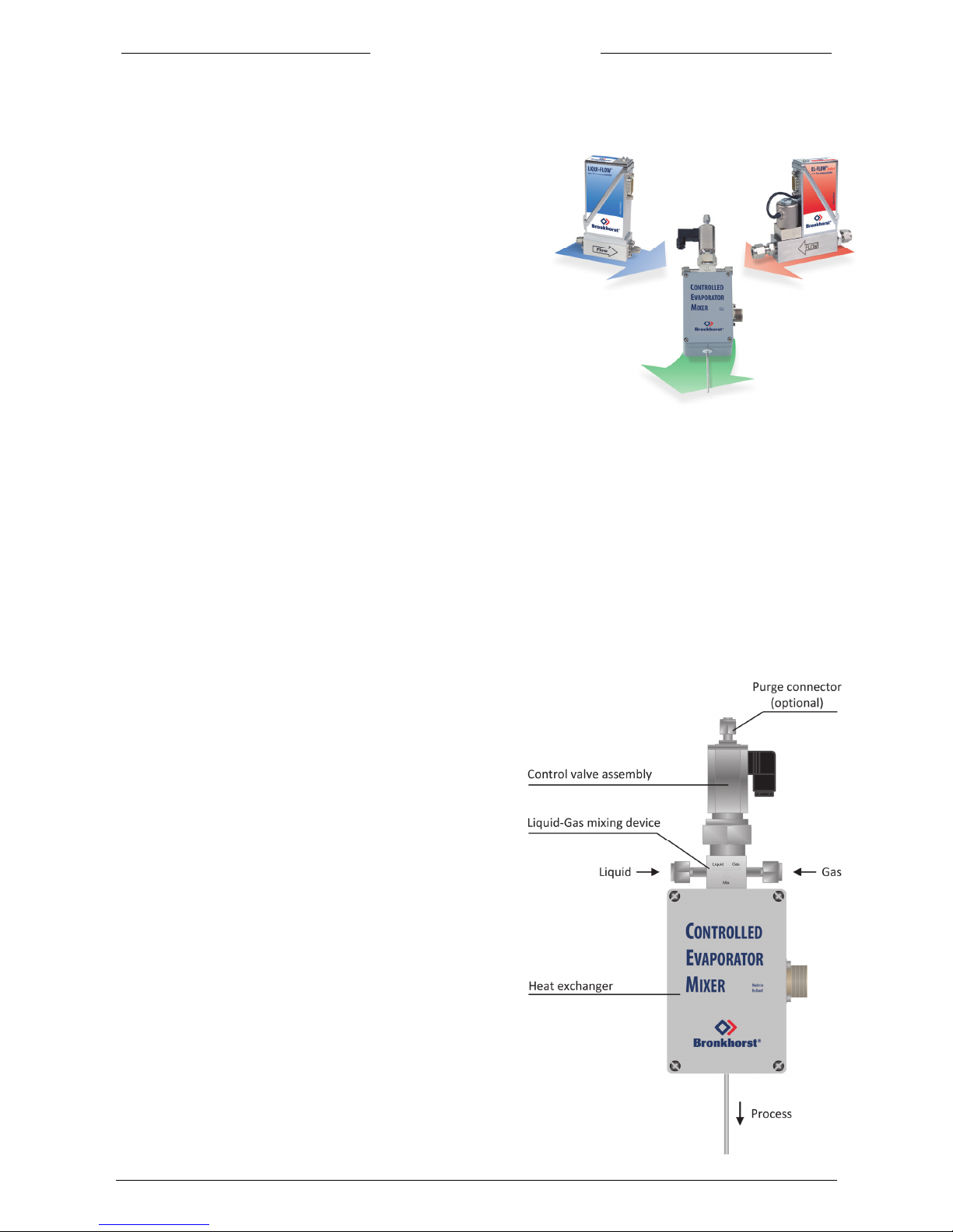
The Bronkhorst
®
series CEM system is a
unique system to realise Mass Flow Control of vapour & mixtures,
containing up to 1000 g/h vapour. A complete system is a
combination of a mixing valve, a heating device, a liquid meter with
control function and a mass flow controller for the carrier gas. The
liquid flow through the liquid meter is controlled by the mixing valve.
A complete system also incorporates a readout/control unit,
including power supply for operation of the different "CEM"-system
devices.
1.2 Principle of operation
The abbreviation "CEM" stands for:
"C" the control of a flow of gas mixture, gas, liquid or liquid/gas mixture
"E" the evaporation of a flow of liquid/gas mixture by means of a temperature controlled heating device
"M" the mixing of a gas and a liquid (vapour).
At room temperature the liquid, for instance water or TEOS, is drawn from a container with an inert gas
blanket, or membrane, and measured by a liquid mass flow meter type m-flow* or LIQUI-FLOW
®
*. The
required flow rate is controlled to the setpoint value by a control valve that forms an integral part of the
"CEM"-system.
A carrier gas, controlled by a MFC* is used to stimulate the evaporation process as a mixing component,
and furthermore to transport the vapour.
The process is highly repeatable and efficient.
Subsequent total evaporation of the liquid is achieved in the "CEM".
* For operation of these devices consult the appropriate instruction manuals.
1.3 CEM set-up
The “CEM” system is built up around 3 different parts;
a control valve, a mixing device and a heat exchanger in
which heat is added to the mixture of fluids for evaporisation
and furthermore to prevent condensation.
The temperature of the heat exchanger is controlled
by a temperature controller which is part of the readout
and control unit.
Page 8

page 8 9.17.010
BRONKHORST®
2 INSTALLATION
2.1 Receipt of equipment
Check the outside packing box for damage incurred during shipment. Should the packing box be damaged,
then the local carrier must be notified at once regarding his liability, if so required. At the same time a report
should be submitted to:
BRONKHORST HIGH-TECH B.V.
RUURLO HOLLAND
Remove the envelope containing the packing list; carefully remove the equipment from the packing box.
Do not discard spare- or replacement parts with the packing material and inspect the contents for damaged
or missing parts.
2.2 Return shipment
When returning material, always describe the problem and if possible the work to be done, in a covering
letter.
It is absolutely required to notify the factory if toxic or dangerous gases have been metered with the
instrument!
This to enable the factory to take sufficient precautionary measures to safe-guard the staff in their repair
department. Take proper care of packing, if possible use the original packing box; seal instrument in plastic
etc.
All instruments must be dispatched with a completely filled in 'declaration on contamination form'. (In the
back of this manual)
Instruments without this declaration will not be accepted.
Note:
If the instruments have been used with toxic or dangerous gases the customer should pre-clean the
instrument.
Important:
Clearly note, on top of the package, the customer clearance number of BRONKHORST HIGH-TECH B.V.,
namely:
NL801989978B01
2.3 Service
If this equipment is not properly serviced, serious personal injury and/or damage to the equipment could be
the result. It is therefore important that servicing is performed by trained and qualified service personnel.
Bronkhorst
®
has a trained staff of servicemen available.
2.4 Mounting position
Bronkhorst® strongly advises to mount the CEM in a vertical position, with the control valve section pointing
upwards and the vapour output pointing downwards.
Avoid installation in close proximity of mechanic vibration or strong heat sources.
2.5 Liquid filling
The purge connector can be used to remove the air from the liquid system. If available, use vacuum to deaerate the valve and liquid flowmeter before filling with liquid.
Page 9

9.17.010
page 9
BRONKHORST®
2.6 In-line filter
Although fluids and piping should be absolutely free from dirt, it is recommended to install inline filters
upstream of the flowmeter(s).
2.7 Fluid connections
The liquid meter should be installed according to its manual. The outlet of this meter should be connected to
the liquid input port of the CEM valve. The CEM valve is controlled by the controller section of the liquid
flowmeter. Electrical connections should be made according to the customer system description.
The outlet of the gas flow controller must be connected to the gas input part of the CEM valve.
The vapour outlet of the CEM should be directly coupled to the process, this tube should be heated at a
temperature higher than the heater in order to assure that the vapour will not condensate in this line. Avoid
“cold spots” in the outlet.
* Note: Always check your system for leaks, before applying fluid pressure. Especially if toxic, explosive or
other dangerous fluids are used.
2.8 Electrical connections
Bronkhorst® recommends to use their standard cables, which have been tested together with the system.
These cables have the right connector, and if loose ends are used, these will be marked to prevent wrong
connection.
2.9 Caution
Each system is pressure tested to at least 1.5 times the working pressure of the process conditions
stipulated by the customer, with a minimum of 8 bar.
This test pressure is stated on the CEM valve with a Red Coloured sticker.
Check test pressure before installing in the line.
If this sticker is not available, or the test pressure is incorrect, the instrument should not be mounted in the
process line and be returned to the factory.
Each instrument is leak tested to at least 2 10
-9
mbar l/s Helium.
2.10 Supply pressure
Do not apply pressure until electrical connections are made. When applying pressure to the system, take
care to avoid pressure shocks in the system, and increase pressure gradually. Be sure that all set points are
at zero when doing so.
2.11 System purging
If corrosive or reactive fluids are used, purging with an inert gas is absolutely necessary, because if the
tubing has been exposed to air, introducing these fluids will tend to clog up or corrode the system due to a
chemical reaction with air or moist air.
Complete, long term purging is also required to remove such fluids from the system before exposing it to air.
It is preferred not to expose the system to air, when working with these corrosive fluids. Cycled purging and
evacuating is preferred.
2.12 Seals
Bronkhorst® has gathered a material compatibility chart from a number of sources believed to be reliable.
However, it is a general guide only. Operating conditions may substantially change the accuracy of this
guide. Therefore is no liability for damages accruing from the use of this guide. The customers application
demands its own specific design or test evaluation for optimum reliability. So check if the seals are correct
for your process. However the CEM system has metal seals for all connections. Only the valve plunger is an
elastomer.
Page 10

page 10 9.17.010
BRONKHORST®
3 Operation
3.1 General
The Bronkhorst® "CEM"-system is designed in such a way that it will meet user process requirements. In
order to achieve good results, it should be operated according to the guidelines stated in the following
paragraphs.
3.2 Power and warm-up
Before switching on power, check if you have connected all devices according to the system description
and/or hook-up diagram. Check the liquid and gas connections, and make sure there are no leakages, turn
on power for at least 30 minutes to warm up flow controllers. For start up of the liquid controller consult the
appropriate manual. During this warming-up period the temperature of the heat exchanger might be brought
up to its operating point.
3.3 Start-up/close-down
Be sure that the temperature of the heat exchanger is in accordance with the process conditions to be
adjusted, and furthermore should all pressure levels have the correct values.
After this has been assured first start bringing up the carrier gas flow to the correct level. Once this flow has
been stabilised, the liquid flow can be applied to the system, by gradually increasing the setpoint of the liquid
controller. Now your “CEM” system should be operating.
When closing down operation of the system proceed in reverse order.
First stop the liquid flow, and after that the gas flow.
Note:
Make sure there is always gas flow whenever liquid flow is present.
Operation example:
Application: Generation of humid gas
The CEM system can be used for generating a certain humidity in a gas stream. The gas flow is controlled
by the F-201 gas flow controller and the humidity, the water, is controlled by the LIQUI-FLOW
®
controller.
The water is mixed with the gas and consequently evaporated. The humidity at a certain temperature
corresponds with a certain ratio of gas and water, this ratio can be set by the flow controllers.
Example:
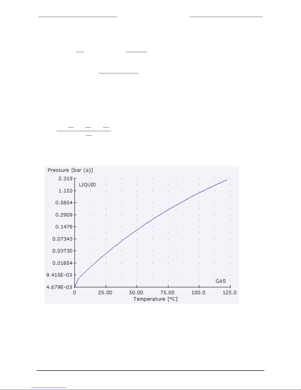
At atmospheric pressure, at 80°C, 2 ln/min Air has to be moistened. Which water flow is needed for a r.h. of
50%. The vapor pressure of water at 80°C is 473.3 mbar according to Fluidat.
At 100% r.h., the (Mole) ratio between gas and water is:
The MoleRatio:
876.0
)3.47325.1013(
3.473
X
So in a gas flow of 2 ln/min, the saturated vapor flow (100% r.h.) is:
752.12876.0
gaswater
X [ln/min]
and in [g/h]
5.83
][4.22
][60][18][752.1
ln
min
min
ln
mol
hmol
g
[g/h]
Page 11
9.17.010
page 11
BRONKHORST®
At 50% r.h., the (Mole) ratio between gas and water:
100.%.
sat
e
e
hr
6.236
100
3.47350
e [mbar]
The moleRatio:
305.0
)6.23625.1013(
6.236
X
so in a gas flow of 2 ln/min, the saturated water flow (50% r.h.) is:
61.02305.0
gaswater
X [ln/min]
and in [g/h]
41.29
][4.22
][60][18][61.0
ln
min
min
ln
mol
hmol
g
[g/h]
Result: at 50% r.h., the waterflow is 29.41 g/h.
Page 12

page 12 9.17.010
BRONKHORST®
4 Cables
The use of standard cables, manufactured by Bronkhorst
®
is recommended.
4.1 EMC and cables
All system set-ups described in this manual carry the CE-mark.
Therefore they have to comply with the EMC requirements as are valid for this kind of equipment.
However compliance with the EMC requirements is not possible without the use of proper cables
and connector/packing gland assemblies.
Screens of cables should be carefully connected at both ends of the cable to the metal housing of the
connector for good EMC behaviour.
For sensors and valves follow the guidelines as explained in the appropriate manuals.
Page 13

APPENDIX
Recommendations for handling
the Bronkhorst
®
DLI
(CEM) system
Vacuum system
Non Vacuum system
Page 14

BRONKHORST®
1
Page 15
Appendix , page 3
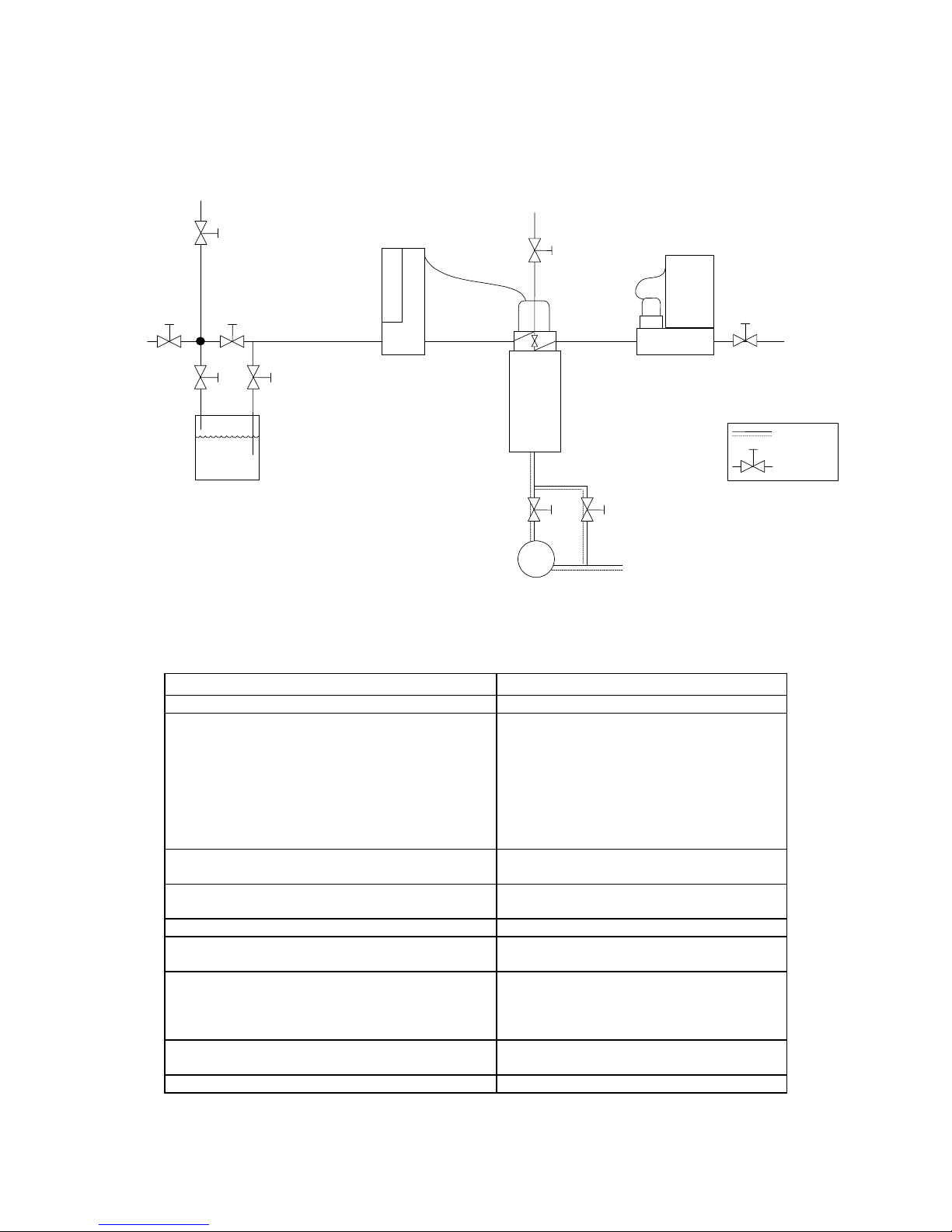
Startup using Vacuum
A) To fill the system:
Procedure: Actions:
A1) Evacuate the lines “Vacuum” Start pumps
A2) Evacuate all lines Close: 2,3,5,10 and 9.
Connect inert gas on carrier gas inlet.
Open : 1,4,7,11.
Give setpoint to gas and liquid control
(the control valves 6 and 8 open).
Pump for a long time.
Remark: if the system is not completely
dry follow procedure of E3, E4, (E5).
A3) Purge line between inert gas source and
valve 2.
Close: 4.
Open valve 2 briefly for some seconds.
A4) Purge line between process gas source and
gas MFC.
Give setpoint = 0 to LFM (6 closes).
Open valve 9 briefly for some seconds.
A5) Pump down liquid supply. Open 3 for some time, close 3.
A6) Pressurize liquid supply. Close 1, give right pressure on inert gas
supply. Open 2, open 3 briefly.
A7) Fill the system with liquid.
(1)
Let gas flow in the carrier gas line during
filling of the system.
Close 7.
Open 5 briefly, allow mixing valve 6 to fill.
A8) Optional: degassing mixing valve. Open 7, a needle valve will be best, to
avoid too much liquid be pumped away.
A9) The system is now ready for use.
Vacuum
Liquid
1
4
35
6
8
10 11
9
MFC
Carrier
Processgas
Vacuum
7
LFM
Inertgassupply
2
Process
Vacuum
Valve
Heatedline
CEM
Liquid Gas
Page 16
BRONKHORST®
Appendix, page 4
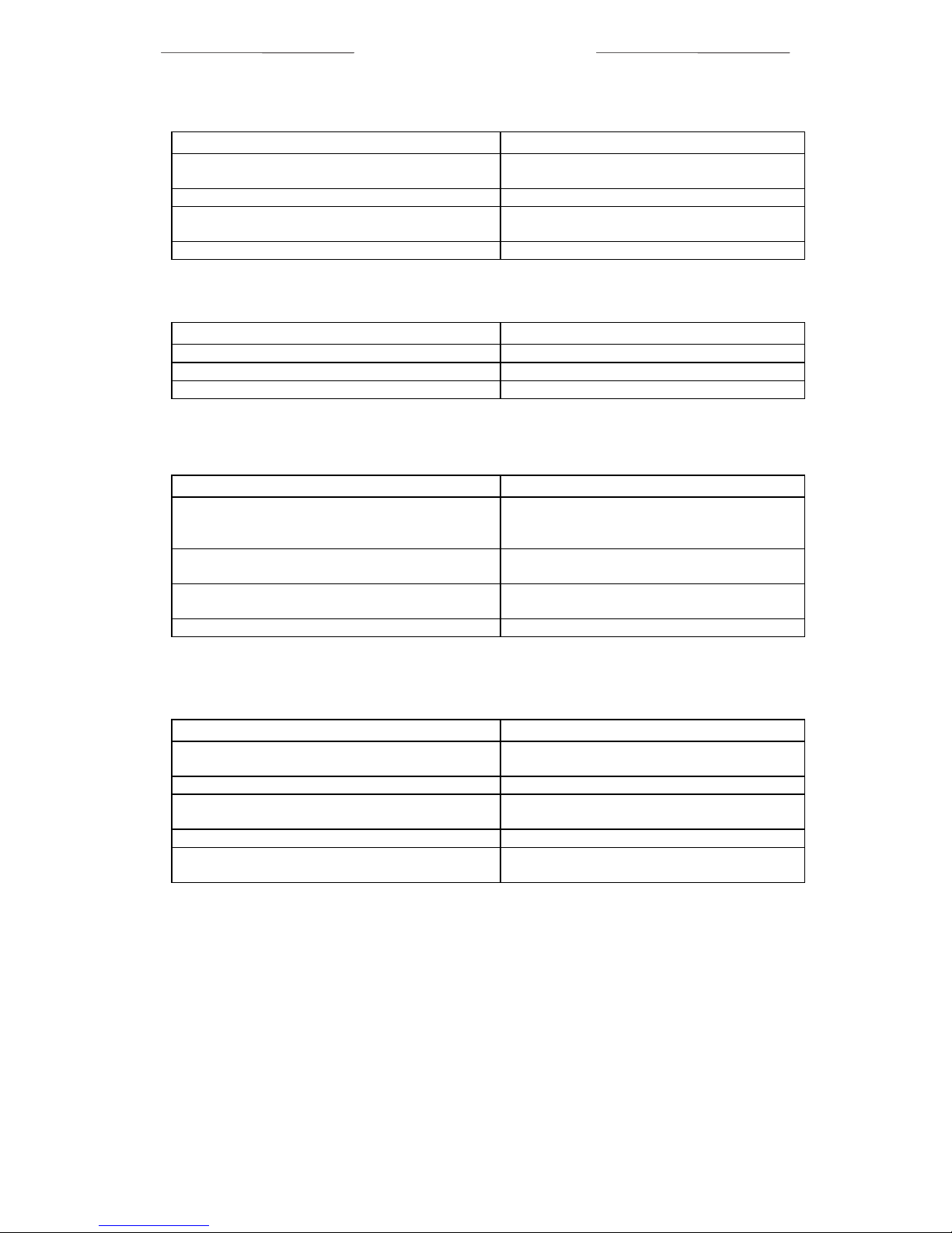
B) To start the process:
Procedure: Actions:
B1)Set the CEM heater at right temperature. Give setpoint to the heater, wait until
temperature is reached.
B2) Start gas flow.
(1)
Open 9. Give setpoint to gas MFC.
B3) Start liquid flow.
(2)
Give setpoint to liquid flow controller, wait
until stabilization.
B4) Connect process. Open 10, close 11.
C) To stop the process:
Procedure: Actions:
C1) Disconnect process. Open 11, close 10.
C2) Stop liquid flow. Give setpoint = 0 to liquid flow controller.
C3) Optional: Stop gas flow.
(1)
Give setpoint = 0 to gas MFC.
D) How to leave system overnight:
Procedure: Actions:
D1) Relief the supply pressure from the liquid
supply and lines.
Close 2, close 5 and open 1 for some
seconds.
Relief pressure inert gas supply, open 2.
D2) Leave system unused. Close 3. Preferably, keep pumping the lines,
close 2, open 1.
D3) Before startup, pressurize liquid supply. Close 1 and open 2.
Open 3 and 5.
D4) System is now ready for use. Proceed according to B.
E) To empty and purge the system:
(3,4)
Procedure: Actions:
E1) Follow procedure “How to leave system
overnight” until “leave system unused”.
See D1 and D2.
E2) Purge liquid out of lines. Open 4 and 7.
E3) Purge lines with inert gas. Close 1.
Open 2 briefly for some time.
E4) Evacuate liquid lines (cont.). Close 2, open 1.
E5) Optional: Repeat last two steps for a few
times.
1
Make sure that the carrier gas is always flowing when the liquid flow is on. Preferably,
let always gas flow in the carrier gas line when the system is filled with liquid.
2
Close supply pressure of the liquid vessel during the process. The pressure controller of
the inert gassupply can influence the stability of the liquid flow controller.
3
If the liquid is reactive or aggressive, be sure to remove air (and water vapor) carefully,
before introducing liquid in the system.
4
If the liquid is reactive, aggressive, poisonous, toxic, or flammable, beware that the system is
purged fully (preferably with inert liquid, E3, E4, E5) before opening the system.
Remarks:
- In case of non-pure liquids, place a filter just before the Liqui-Flow.
- Mount the CEM system vertical.
Page 17
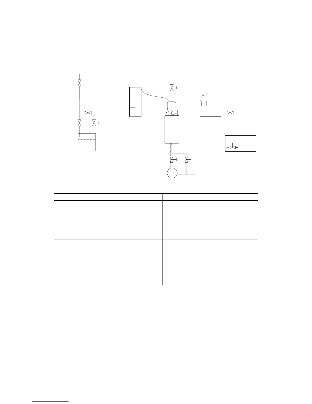
Appendix, page 5
Startup without using Vacuum
Liquid
4
3 5
6
8
10 11
9
MFC
Carrier
Processgas
Atmospheric / waste
7
LFM
Inertgassupply
2
Process
Atmospheric / waste
Valve
Heatedline
CEM
Liquid Gas
A) To fill the system:
Procedure: Actions:
A1)Purge all lines Close: 3, 5 and 10.
Connect inert gas on carrier gas inlet.
Open : 2, 4, 7, 9 and 11.
Give setpoint to gas controller, the control
valve 8 opens.
Give setpoint = 0 to liquid - flow controller
Purge for a long time.
A2) Pressurize liquid supply. Close 4, give right pressure on inert gas
supply. Open 3.
A3) Fill the system with liquid.
(1)
Let gas flow in the carrier gas line during
filling of the system.
Open 5 briefly, allow mixing valve 6 to fill.
Wait until all gas bubbles left the system,
then close 7.
A4) The system is now ready for use.
1
Make sure that the carrier gas is always flowing when the liquid flow is on. Preferably,
let always gas flow in the carrier gas line when the system is filled with liquid.
Page 18

BRONKHORST®
Appendix, page 6
B) To start the process:
Procedure: Actions:
B1) Set the CEM heater at right temperature. Give setpoint to the heater, wait until the
temperature is stabilized.
B2) Start gas flow.
(1)
Give setpoint to gas MFC.
B3) Start liquid flow.
(2)
Give setpoint to liquid flow controller, wait
until stabilization.
B4) Connect process. Open 10, close 11.
C) To stop the process:
Procedure: Actions:
C1) Disconnect process. Open 11, close 10.
C2) Stop liquid flow. Give setpoint = 0 to liquid flow controller.
C3) Optional: Stop gas flow.
(1)
Give setpoint = 0 to gas MFC.
D) How to leave system overnight:
Procedure: Actions:
D1) Relief the supply pressure from the liquid
supply and lines.
Close 5.
Relief pressure inert gas supply. Open 2.
D2) Leave system unused. Close 3. Close 2.
D3) Before startup, pressurize liquid supply. Open 2.
Open 3 and 5.
D4) System is now ready for use. Proceed according to B.
E) To empty and purge the system:
(3,4)
Procedure: Actions:
E1) Follow procedure “How to leave system
overnight” until “leave system unused”.
See D1 and D2.
E2) Purge liquid out of lines. Open 4 and 7, open 2
E3) Purge lines with inert gas. Purge for long time.
E4) Optional: Purge with inert liquid. Connect inert liquid to inert gas supply .
Proceed according to E2.
E5) Optional: Alter E3 and E4 for a few times.
1
Make sure that the carrier gas is always flowing when the liquid flow is on. Preferably,
let always gas flow in the carrier gas line when the system is filled with liquid.
2
Close supply pressure of the liquid vessel during the process. The pressure controller of
the inert gas supply can influence the stability of the liquid flow controller.
3
If the liquid is reactive or aggressive, be sure to remove air (and water vapor) carefully,
before introducing liquid in the system.
4
If the liquid is reactive, aggressive, poisonous, toxic, or flammable, beware that the system is
purged fully (preferably with inert liquid, E3, E4, E5) before opening the system.
Remarks:
- In case of non-pure liquids, place a filter just before the Liqui-Flow.
- Mount the CEM system vertical.
 Loading...