

Page 1
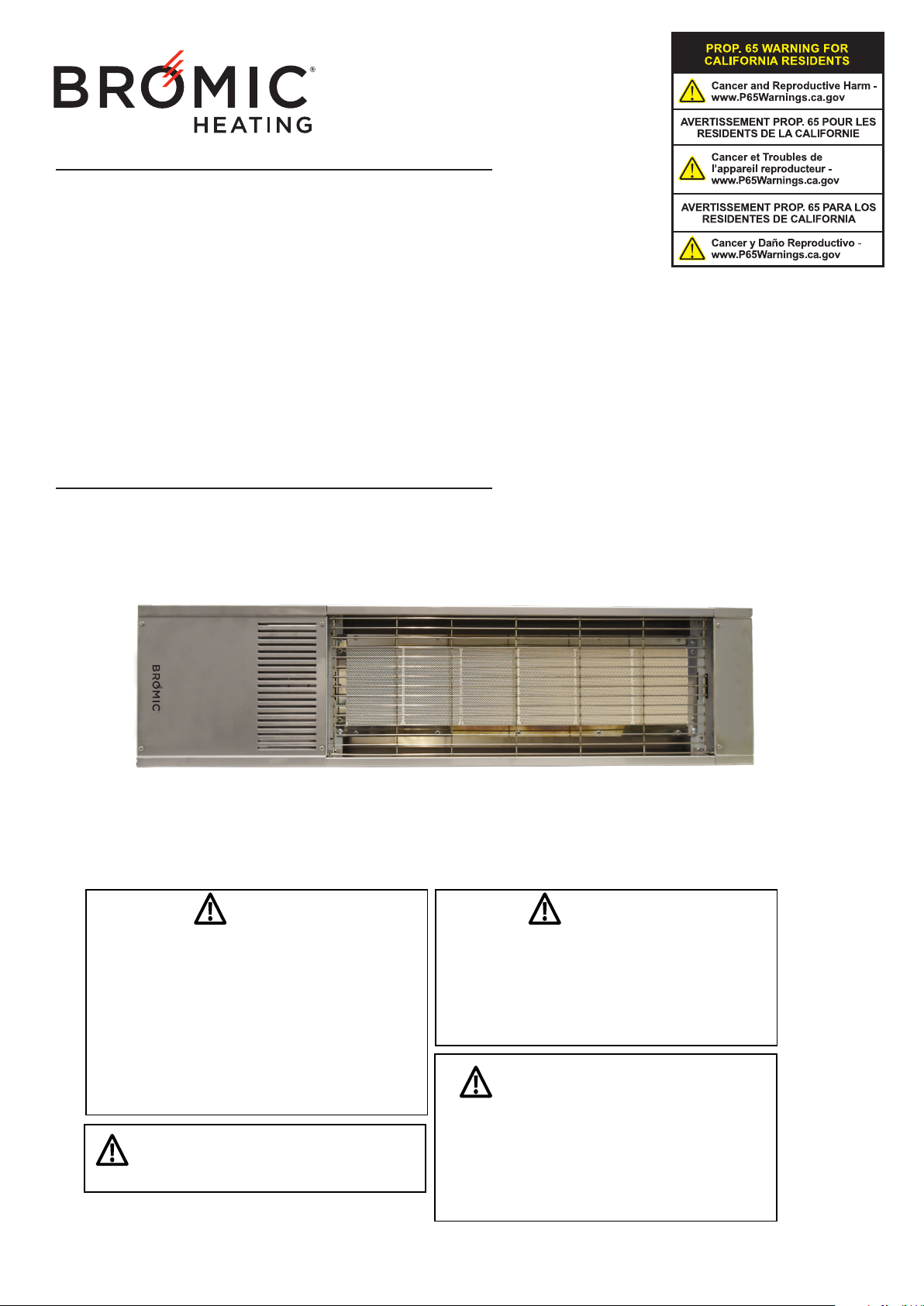
COBALT GAS HEATER
BY BROMIC
INSTALLATION, INSTRUCTION AND
SERVICE MANUAL
SUITABLE FOR GAS RADIANT HEATER MODELS:
COBALT GAS HEATER
If you smell gas:
1. Shut o gas to the appliance
2. Extinguish any open ame
3. If odor continues, keep away from the
appliance and immediately call your gas
supplier or re department
WARNING:
For either indoor or outdoor installation.
NOT FOR USE IN RESIDENTIAL DWELLINGS
Version 2.1 USA - CANADIAN
DANGER
WARNING
Do not store or use gasoline or other ammable
vapor and liquids in the vicinity of this or any
other appliance.
An LP-cylinder not connected for use shall not be
stored in the vicinity of this or any other appliance.
WARNING: Improper installation,
adjustment, alteration, service or maintenance
can cause property damage, injury or death.
Read the installation, operating and
maintenance instructions thoroughly before
installing or servicing this equipment.
Page 2
IMPORTANT
This manual contains important information about the assembly, operation, and mainte-
nance of Cobalt Gas Heaters. Please pay close attention to the important safety informa-
tion shown throughout this instruction manual. Any safety information will be
accompanied by thefollowing safety alert symbols:
DANGER, WARNING, IMPORTANT
• READ THIS MANUAL CAREFULLY before installing or
servicing this product.
• Improper installation, operation, or maintenance can result in
death, severe injury, or property damage.
• Installation must be carried out by Authorized person/s in
accordance with local codes, or in the absence of local codes,
with the National Fuel Gas Code, ANSI Z223.1/ NFPA 54,
Natural Gas and Propane Installation Code, CSA B149.1, or
Propane Storage and Handling Code, B149.2.
• The heater, when installed, must be electrically grounded in
accordance with local codes or, in the absence of local codes,
with the National Electrical Code, NFPA 70 or the
Canadian Electrical Code, CSA C22.1.
• For either outdoor or non-residential indoor use only.
NOT FOR USE IN RESIDENTIAL DWELLINGS.
This heater is not approved for use in any indoor residential
applications.
• This appliance MUST be protected from rain.
Telephone: 1300 276 642 (within Australia) or +61 2 9748 3900 (from overseas) Fax: +61 2 9748 4289
Note: Bromic Heating Pty Ltd reserves the right to make changes to specications, parts, components and equipment without prior notication.
This Installation, operation and service manual may not be reproduced in any form without prior written consent from Bromic Heating Pty Ltd.
2
Head Oce: 10 Phiney Place, Ingleburn, Sydney, NSW 2565 Australia
Email: [email protected] Web: www.bromic.com/heating
www.bromic.com/heating
Page 3
CONTENTS
IMPORTANT NOTES & WARNINGS 4
PRODUCT OVERVIEW 5
PRODUCT DESCRIPTION 5
SPECIFICATIONS 5
GENERAL INFORMATION 6
PRODUCT FEATURES 6
INSTALLATION REQUIREMENTS 6
GAS REQUIREMENTS 6
INSTALLATION CLEARANCES 7
INSTALLATION INSTRUCTIONS 8
HEATER INSTALLATION INSTRUCTIONS 8
GAS SUPPLY INSTALLATION 9
POWER SUPPLY INSTALLATION 9
LEAKAGE TEST 9
HEAT DEFLECTOR INSTALLATION INSTRUCTIONS 10
CEILING MOUNT POLE INSTALLATION INSTRUCTIONS 10
OPERATING INSTRUCTIONS 12
TURNING THE APPLIANCE ON 12
TURNING THE APPLIANCE OFF 12
MAINTENANCE AND SERVICING 12
REGULAR SERVICE REQUIREMENTS 12
EXTERIOR SERVICING 12
TROUBLE SHOOTING 15
www.bromic.com/heating
3
Page 4
IMPORTANT NOTES AND WARNINGS
• Do not use the heater until all connections have been
WARNING
• CHILDREN AND ADULTS SHOULD BE ALERTED TO
THE HAZARDS OF HIGH SURFACE TEMPERATURES
AND SHOULD STAY AWAY TO AVOID BURNS OR
CLOTHING IGNITION
• YOUNG CHILDREN SHOULD BE CAREFULLY
SUPERVISED WHEN THEY ARE IN THE AREA OF THE
HEATER
• DO NOT USE OR STORE FLAMMABLE MATERIALS
NEAR THIS APPLIANCE
• CLOTHING OR FLAMMABLE MATERIALS SHOULD
NOT BE HUNG FROM THE HEATER OR PLACED ON
OR NEAR THE HEATER
• DO NOT SPRAY AEROSOLS OR FLAMMABLE
MATERIALS IN THE VICINITY OF THIS APPLIANCE
WHILE IT IS IN OPERATION
• ANY GUARD OR OTHER PROTECTIVE DEVICE
REMOVED FOR SERVICING THE HEATER (conducted
by an authorized person) MUST BE REPLACED PRIOR
TO OPERATING THE HEATER
• INSTALLATION AND REPAIR SHOULD BE DONE
BY A QUALIFIED SERVICE PERSON. THE HEATER
SHOULD BE INSPECTED BEFORE USE AND AT LEAST
ANNUALLY BY A QUALIFIED SERVICE PERSON
Failure to follow the warnings and instructions in this
manual could result in severe personal injury, death or
property damage.
• This Installation, Operation and Maintenance manual
should not be removed from the site of installation.
• Installer should leave manual with the customer for
future reference.
• This Appliance is for outdoor and non-residential
indoor
areas only. See page 6 for detailed specications and
diagrammatical representations of required indoor
area.
• Do not perform maintenance until heater has
been turned off, power disconnected, and heater
temperature has cooled to room temperature.
• Do not expose the burner to water or moisture. THE
APPLIANCE MUST BE PROTECTED FROM RAIN .
• Do not use the heater if any of these parts are exposed
to water until the appliance is inspected or repaired by
an authorized service person.
• The installer is to ensure that the requirements of the
local authority, local gas fitting regulations, municipal
building codes, and any other relevant statutory
regulations are carried out.
• Certain materials or items, when stored under or near
the appliance, will be subjected to radiant heat and
could be seriously damaged. Ensure combustible
materials eg. overhead structures, walls, floors,
furniture, fixtures and plants are kept outside the
installation clearances (Pg.7).
• The whole gas system, hose assembly, regulator, pipes,
and burner should be inspected for damage and leaks
before use and at least annually by an authorized
person for the life of the heater.
• All leak tests should be done with a soap solution.
Never use an open flame to check for leaks.
leak tested by an authorized person.
• Inspect the hose assembly before each use of the
appliance.
• The hose assembly must be replaced prior to the
appliance being put into operation if there is evidence
of excessive abrasion or wear, or if the hose is
damaged.
• The replacement hose assembly must be CSA
approved.
• The hose assembly is not to be located in areas where
the hose may be subject to accidental damage
• This radiant heater is NOT intended to be installed on
recreational vehicles and/or boats.
• Repair to be carried out ONLY by an authorized
person.
• Improper installation, adjustment, or alteration can
cause personal injury, property damage, or even
death.
• Do not attempt to alter the unit in any manner.
• Remove transit protection before use.
• Never operate the heater in an explosive environment
such as areas where gasoline or other flammable
liquids or vapours are stored.
• Turn o the gas supply immediately if smell of gas is
detected.
• Do not paint any surface of the heater.
• Do not throw objects at the heater.
• The fascia breaks, discontinue use, disconnect power
and gas and isolate area affected by breakage.
• Control compartment, burner and circulation air
passageways of the heater must be kept clean.
Frequent cleaning may be required as necessary.
• Turn Gas Supply off when not in use.
• Check the heater immediately if any of the following
occurs:
» The heater does not reach temperature.
» The burner makes popping noise during use (a
slight noise is normal when the burner is ignited
or extinguished).
• Young children should be supervised to ensure that
they don’t play with the appliance.
• This appliance is not intended for use by young or
infirm persons unless they have been adequately
supervised by a responsible person to ensure that they
can use the appliance safely.
• Check for damage to the appliance regularly. If
damage to the cord, plug or appliance is suspected,
discontinue use immediately and contact the supplier
or qualified person for repair.
• If the cord, plug or appliance is damaged, unplug from
the outlet, discontinue use immediately, and only an
authorized person or similar may repair the unit.
• Avoid inhaling fumes emitted from the heater’s first
use. Smoke and odour from the burning of oils used in
manufacturing will appear. Both the smoke and odour
will dissipate after approximately 30 minutes.
• Ensure that a watertight seal is maintained on the
electrical control box at all times
• Regularly check for damage to the rubber seals. If
damage to the rubber seals is suspected, discontinue
use immediately, switch o power and contact the place
of purchase or authorized service technician for repair.
4
www.bromic.com/heating
Page 5
PRODUCT OVERVIEW
PRODUCT DESCRIPTION
The Cobalt Gas Heaters are designed to provide effective heating whilst offering an appealing design.
The heaters incorporate full function electronic controls, allowing them to be operated remotely from a conveniently
located switch.
SPECIFICATIONS
Manufactured by Bromic Heating Pty Ltd
Approval No. 4009079
Gas type Propane (LPG) Natural Gas
Gas Consumption 22,100 BTU 28,000 BTU
Max. Line Pressure 14” W.C. 14” W.C.
Min. Line Pressure 11” W.C. 6” W.C.
Manifold Pressure
At Valve Test Point
Orifice Size 1.37mm 2.35mm
Weight 42lb 42lb
Voltage 110 Volt 110 Volt
Current < 2 Amp < 2 Amp
10” W.C. 5” W.C.
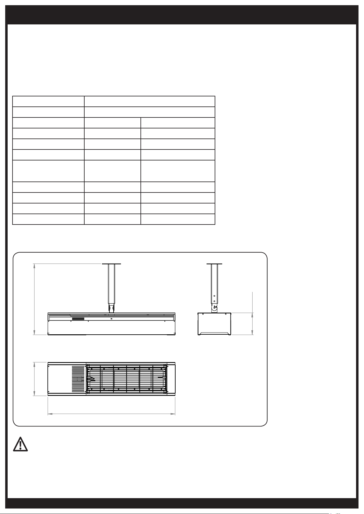
COBALT GAS HEATER DIMENSIONAL DETAILS
21.0"
6.5"
10"
37.6"
IMPORTANT
This must be installed by authorized persons only in accordance with local codes, or in the absence of local codes,
with the National Fuel Gas Code, ANSI Z223.1/NFPA 54, Natural Gas and Propane Installation Code, CSA B149.1, or
Propane Storage and Handling Code, B149.2.
This appliance must be protected from rain. Install under a protective cover.
www.bromic.com/heating
5
Page 6
INSTALLATION REQUIREMENTS
IMPORTANT
• Not for use in residential dwellings.
This heater is not approved for use in any indoor
residential applications. This includes, but is not
limited to, attached garage, solarium, living quarter,
etc. Installation in residential indoor spaces may
result in death, asphyxiation, serious injury, or
property damage.
• The stated clearance to combustible materials
represents a surface temperature of 90ºF above
room temperature. Building materials with a low
heat tolerance (such as plastic, vinyl siding, canvas,
tri-ply, etc.) may be subject to degradation at lower
temperatures. It is the installer’s responsibility to
assure that adjacent materials are protected
from degradation.
• Heater ventilation must comply with state and local
codes. Never use heater in a fully enclosed area.
• It is required that areas above the heater be
properly vented to allow for necessary combustion
air and removal of combustion gases.
IMPORTANT
ENCLOSURE REQUIREMENTS FOR
NON-RESIDENTIAL INDOOR USE
• Not for use in residential dwellings.
This heater is not approved for use in any indoor
residential applications. This includes, but is not limited to,
attached
garage, solarium, living quarter, etc. Installation
in residential indoor spaces may result in death,
asphyxiation, serious
injury, or property damage.
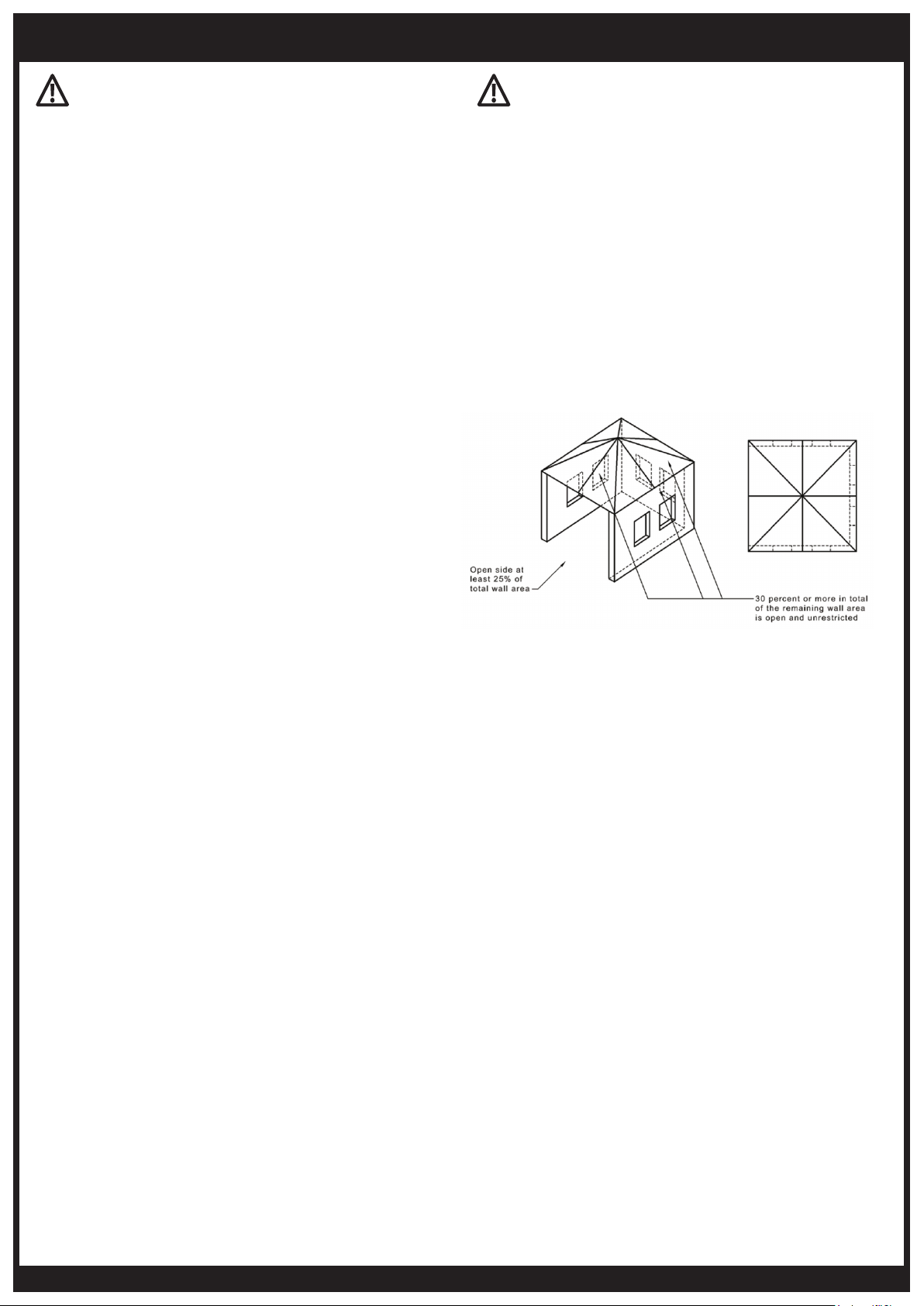
• The appliance must not be used in a room smaller than
250 cubic meters (ref. Diagram A below).
• The appliance must only be used in a well ventilated
area
(ref. Diagram A below).
• Heaters shall be provided with natural or
mechanical means to supply and exhaust at least
4 cfm per 1,000 BTU per hour of heater input.
Exhaust openings for removing the flue
products shall be above the level of the heaters.
ENCLOSURE REQUIREMENTS FOR
OUTDOOR USE
• This appliance shall only be used in a well ventilated,
above ground open air space.
This appliance shall only be used in a space:
- with natural ventilation
- without stagnant areas
- where gas leakage and products of combustion are
rapidly dispersed by wind and natural convection
Any enclosure in which the appliance is used shall
comply with one of the following:
1. An enclosure with walls on all sides, but with no
overhead cover. With at least one permanent
opening at ground level (ref. Appendix A, Example 1).
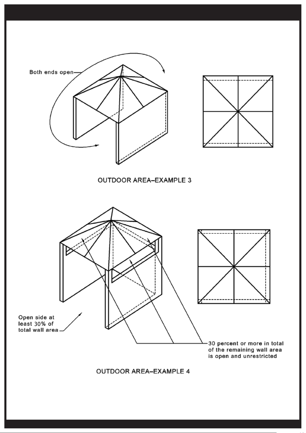
2. Within a partial enclosure which includes an
overhead cover and no more than two side walls.
These side walls may be parallel, as in a breezeway,
or at right angles to each other (ref. Appendix A,
Example 2 & 3).
3. Within a partial enclosure which includes an
overhead cover and three side walls, as long as 30
percent or more of the horizontal periphery of the
enclosure is permanently open, and at least 30%
of the remaining wall area is open and unrestricted
(ref. Appendix A, Example 4).
DIAGRAM A - INDOOR AREA
• Heaters to be installed in Aircraft Hangars must be
installed in accordance with the Standard for Aircraft
Hangars, ANSI/NFPA 409.
• Heaters to be installed in Public Garages must be
installed in accordance with the Standard for Parking
Structures ANSI/NFPA 88A.
• Heaters must be installed so that minimum clearances
marked on the heaters will be maintained from vehicles
parked below the heater.
GAS REQUIREMENTS
Cobalt LPG Models:
• Use Propane (LPG) gas only
• The approved manifold pressure to the appliance is
10”W.C.
• The MIN inlet pressure to the appliance is 11” W.C
• The MAX inlet pressure to the appliance is 14” W.C
Cobalt Natural Gas Models:
• The approved manifold pressure to the appliance is
5”W.C.
• The MIN inlet pressure to the appliance is 6” W.C
• The MAX inlet pressure to the appliance is 14” W.C
6
www.bromic.com/heating
Page 7
INSTALLATION REQUIREMENTS CONTINUED...
INSTALLATION CLEARANCES
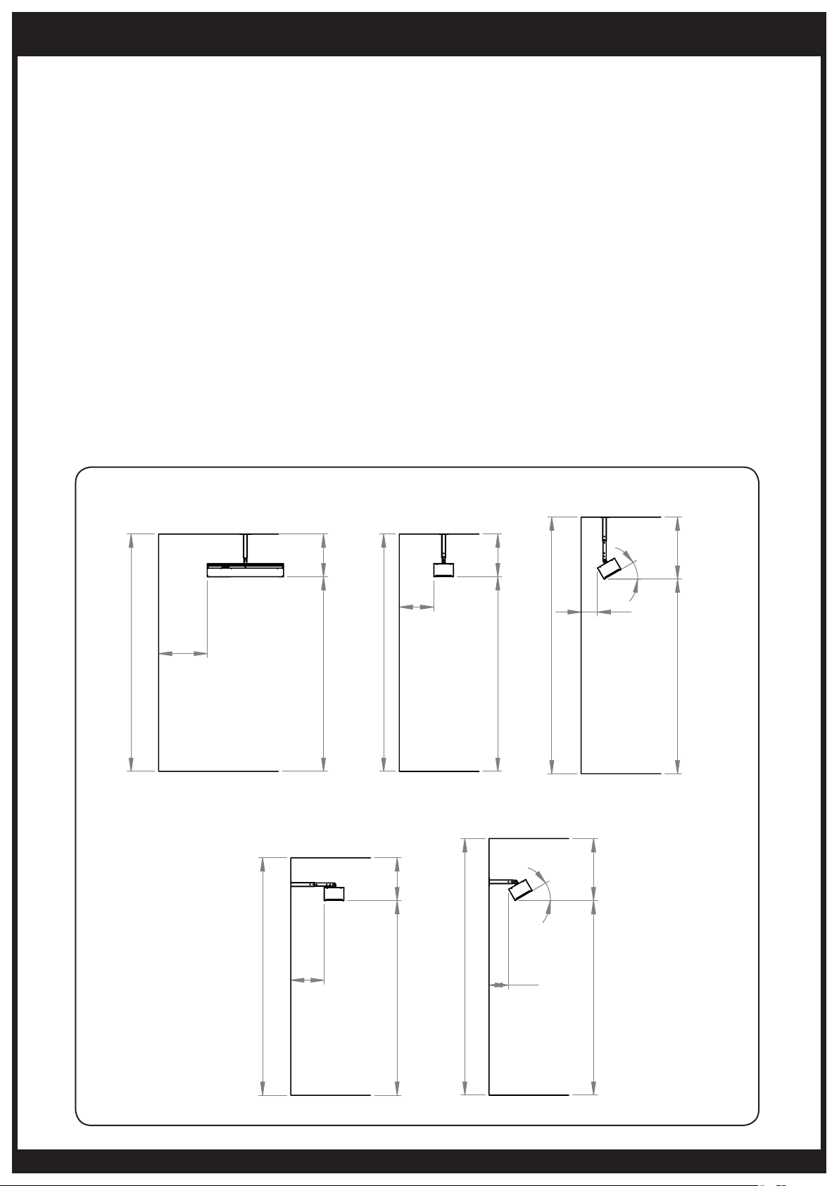
When selecting the installation location for the Cobalt
Gas Heater, the following minimum clearances to
combustible materials must be followed.
Additional clearance may be required for glass, painted
surfaces or other materials which may be damaged by
radiant or convection heat. It is the installers responsibility
to ensure that adjacent materials are not subject to
degradation.
Fire Sprinklers must be located at an appropriate distance
from each heater to avoid accidental activation of the
sprinkler. Ethylene glycol or propylene glycol must never be
used in fire sprinkler systems where heaters are present as
these substances may become flammable when heated. A
fire sprinkler professional must be consulted when heaters
are installed where fire sprinklers are present to insure that
heaters and the fire sprinkler system are properly integrated.
Specific guidelines can be found in NFPA 13 regarding
design and specifications for Fire Sprinkler Systems near
heaters.
Care should be taken to ensure that the heater is not
installed:
• Where heat/ignition can cause damage to gas
cylinders/lines
• Near combustible materials
• In open locations subject to rain
• In areas without sufficient clearances (refer below)
Note: Heater should be installed in such a way so as to
allow adequate;
• Clearance around air openings to combustion
chamber
• Clearance from combustible material
• Provisions for accessibility and clearance for
combustion and ventilating air supply.
WARNING
Certain materials or items, when stored under or near
the appliance, will be subjected to radiant heat and
could be seriously damaged.
Clearance to combustible materials in front of the heater
must be a minimum of 48”.
Ceiling Mount Face Down Ceiling Mount Face Down Ceiling Mount Face Angled
21"
117"
24"
17"
117"
96"
Wall Mount Face Down Wall Mount Angled
96" 21"
127"
30°
8"
31" 96"
30°
31" 96"
117"
16"
96" 21"
127"
www.bromic.com/heating
10"
7
Page 8
INSTALLATION INSTRUCTIONS
HEATER INSTALLATION INSTRUCTIONS
WARNING
Installation must be done by a qualified service person.
This appliance must be installed and used in accordance
with local codes, or in the absence of local codes, with the
National Fuel Gas Code, ANSI Z223.1/NFPA 54, Natural Gas
and Propane Installation Code, CSA B149.1, or Propane
Storage and Handling Code, B149.2 and must meet all the
requirements stipulated in the “Installation Requirements”
section of this manual.
CAUTION
Please see specifications for the weight of the Heater. The
installer of the Cobalt Gas Heaters must comply with all
relevant State Occupational Health & Safety Regulations.
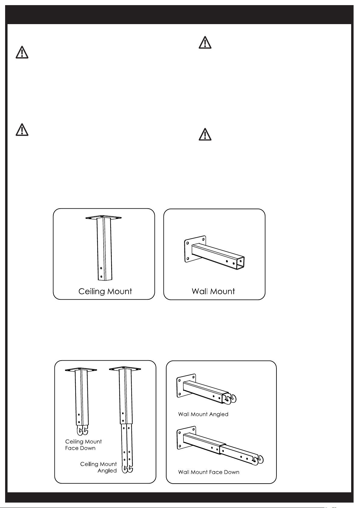
STEP 1:
Attach mounting bracket to ceiling or wall using fasteners appropriate for
the surface. Ensure the bracket is firmly secured with fasteners in all 4 holes
before proceeding.
WARNING
When mounting the heater, ensure the anchoring
to the structure is of sufficient strength, quality and
workmanship to support the weight of the heater
and any other load that could be applied to the
fixture.
The Heater shall be firmly and securely attached
to the wall. For Brick and masonry , use M8 “Flush
Head” “Dynabolts” (or equivalent). For Wood /
Timber fixtures , use suitable screw fixings no less
than 60mm in length.
WARNING
Heater must be mounted horizontal in the
lengthwise direction.
Heater must be mounted in a fixed position
independent of gas and electrical supply lines.
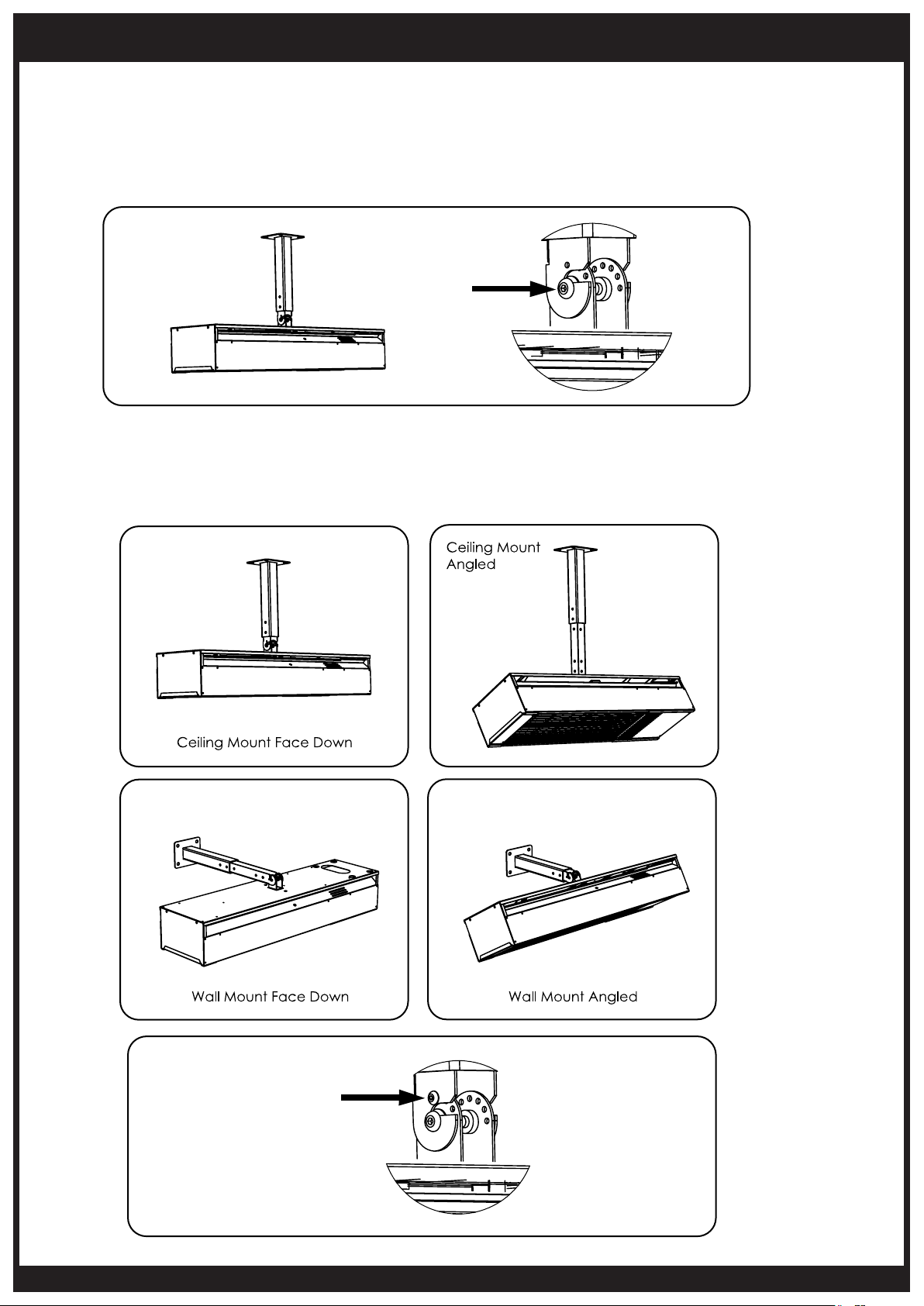
STEP 2:
Assemble extension arm to the bracket.
Position of the extension arm must be set as shown below for face down
or angled mounting. These positions must be used to ensure correct
clearance of the heater from combustible materials. Secure with 2x bolts
and nuts supplied.
8
www.bromic.com/heating
Page 9
INSTALLATION INSTRUCTIONS CONTINUED...
STEP 3:
Ensure 2x screws are assembled to the bracket at the back of the heater. Bring
heater up to the extension arm and hang the heater on the bracket by hooking the
2x screws into the mounting slots. Tighten the 2x screws to secure heater.
STEP 4:
Position the heater at correct angle for the selected mounting option. Insert 2x
screws and nuts supplied to lock the heater at correct angle.
www.bromic.com/heating
9
Page 10
INSTALLATION INSTRUCTIONS CONTINUED...
GAS SUPPLY INSTALLATION
WARNING
• All gas supply installation work must be performed by
trained and authorized person(s) and comply with the
requirements of local Gas Installation Codes.
• All Piping Joints should be tested for leaks with a soapy
water solution before use.
• Gas hose must be located out of pathway where people
may trip over it, or in areas where the hose may be subject
to accidental damage.
Verify the type of gas supply complies with the appliance
rating plate, located at the back of the heater.
The inlet connection to the heater control box is a 1/2” NPT
Female.
The appliance is supplied with an approved manual isolating
valve. The installer must ensure that it is installed with the
heater in accordance to local Gas Installation Codes.
Gas supply pressure must be limited to 14” W.C. If gas line
pressure exceeds this level, a separate pressure reducing
regulator must be installed.
The appliance and must be disconnected from the gas supply
piping system during any pressure testing of that system at
test pressures in excess of 1/2 psi (3.5kPa).
The appliance must be isolated from the gas supply piping
system by closing its individual manual shutoff valve during
any pressure testing of the gas supply piping system at test
pressures equal to or less than 1/2 psig (3.5kPa).
Tighten all the connections and then turn on the gas supply.
Check for gas leakage with a soapy water solution. (See
section titled “Leakage Test”).
Do not use an open flame to check for leaks.
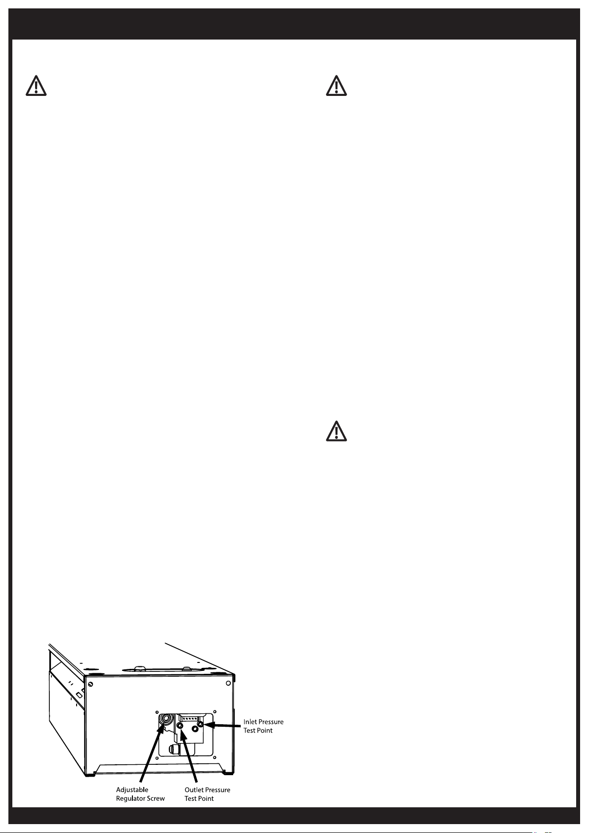
When the heater is operating, check gas pressure at the outlet
point and ensure the manifold pressure to the heater is:
LPG: 10” W .C
NG: 5” W .C.
To check and adjust the appliances internal valve regulator:
Remove the cover panel. Remove the regulator cover cap.
Unscrew and remove the outlet test point plug.
Connect a manometer to outlet test point. Measure the
regulator outlet pressure. Adjust the pressure by turning
the regulator screw. Adjust the pressure according to the
manifold pressure noted above. Replace regulator cover cap.
Replace outlet test point plug and ensure it is tightened and
no gas leak. Replace cover panel.
POWER SUPPLY INSTALLATION
WARNING
The heater, when installed, must be electrically
grounded in accordance with local codes or, in the
absence of local codes, with the National Electrical
code, NFPA 70 or the
Canadian Electrical Code, CSA C22.1.
This heater is equipped with a three-prong
(grounding) plug for your protection against shock
hazard and should be plugged directly into a
properly grounded three-prong receptacle. Do not
cut or remove the grounding prong from this plug.
The Cobalt Gas Heater comes standard with 36”
of power cord in addition to the Approved 3 pin
power plug.
If an appropriate power socket is available, the
heater can be plugged into this power socket and
operated using the on/off switch supplied on the
power socket. Alternatively, the power installation
can be tailored to suit the site requirements by an
Authorized Electrician.
Keep electrical supply cord away from any heated
surface and flue gasses (see warnings on page 11).
Please Note:
Cobalt Gas Heaters do not have their own on/
off switch. Operation should be controlled via the
mains power.
WARNING
Ensure that power socket is switched o before
plugging in power cord.
LEAKAGE TEST
Gas connections on the heater are leak tested at the
factory prior to shipment. A complete gas tightness
check must be performed at the installation site due
to possible mishandling in shipment or excessive
pressure being applied to the heater. Check ALL
connections.
• The heater must be checked with the gas supply
turned on.
• Make sure the safety control valve is in the OFF
position.
• Make a soap solution of one part liquid detergent
and one part water. The soap solution can be
applied with a spray bottle, brush or rag. Soap
bubbles will appear in case of a leak.
• Turn the gas supply ON.
• In case of a leak, turn o the gas supply. Tighten
any leaking fittings, then turn the gas supply on
and recheck.
• Never leak test while smoking.
10
www.bromic.com/heating
Page 11
INSTALLATION INSTRUCTIONS CONTINUED...
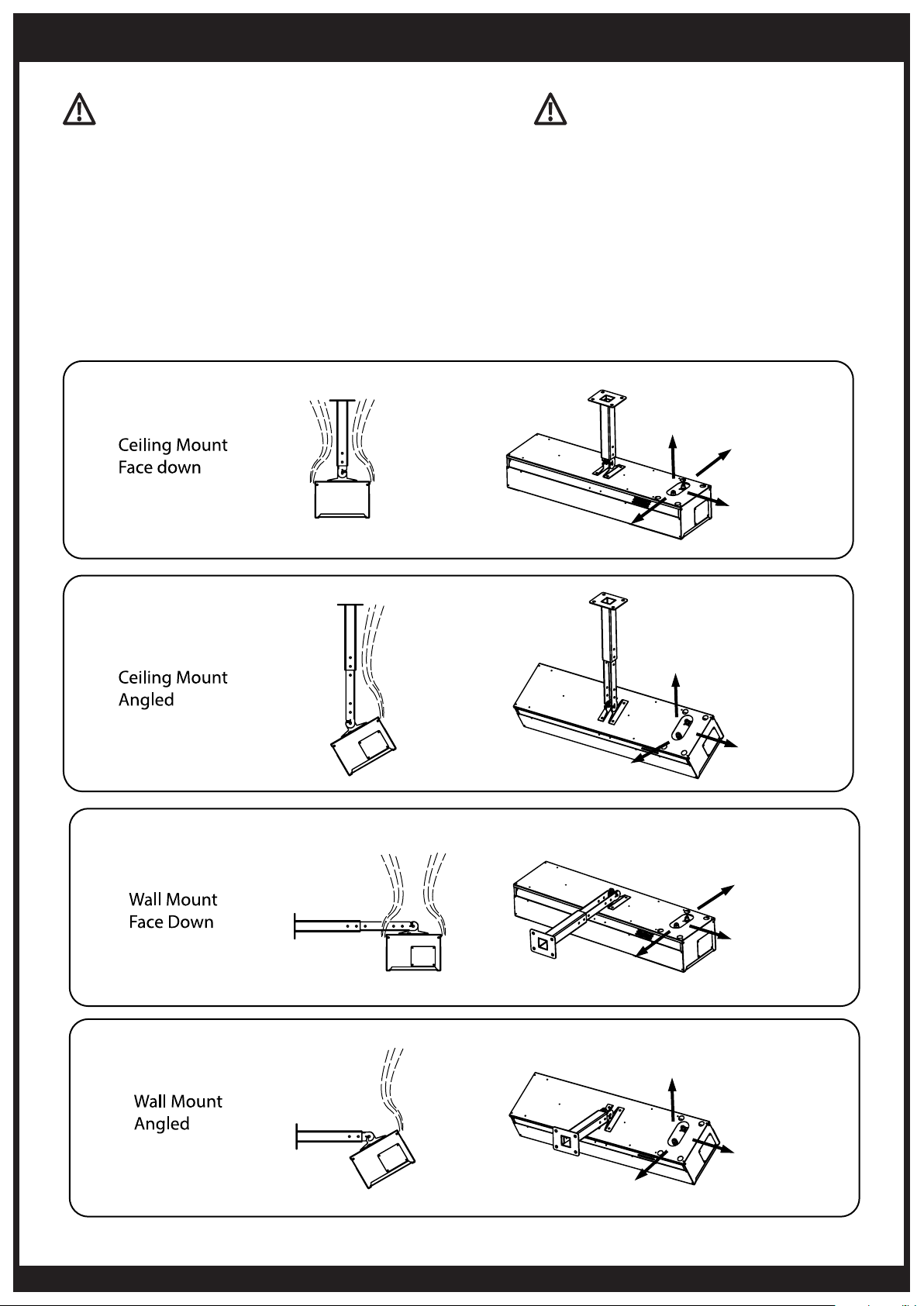
IMPORTANT
The gas hose & electrical supply cord must be kept away
from combustion gases of the heater.
The below diagrams illustrate where combustion gasses
exit the heater for each heater mounting position, and what
positions the gas hose and electrical supply cord must exit
the heater to ensure they are kept away from combustion
gasses.
The installer must ensure the gas hose and electrical supply
cord cannot come into contact with
combustion gasses.
IMPORTANT
The gas hose & electrical supply cord must be
kept away from heater surfaces and mounting
bracket.
When the heater is on the heater surfaces and
mounting bracket reach high temperatures.
The installer must ensure the gas hose and
electrical supply cord cannot come into contact
with the heater surfaces and mounting bracket.
www.bromic.com/heating
11
Page 12
OPERATING INSTRUCTIONS
TURNING THE APPLIANCE ON
1. Ensure that gas installation and power installation has
been carried out in accordance with the manufacturers
instructions outlined in this document.
2. Turn on gas supply.
3. Ensure correct gas supply pressures are set.
4. Switch on power to heater.
5. If Gas heater does not light, turn power off.
6. Wait 5 seconds before turning power back on. If
heater does not ignite after 5 attempts, consult the
troubleshooting section of this manual, or contact Bromic
Heating Pty. Ltd for service information.
TURNING THE APPLIANCE OFF
1. For temporary shutdown, turn off power.
2. For permanent shutdown, turn o power and shut off gas
supply.
NOTE: The appliance must be completely shut off for a period
of 5 minutes before being relighted.
MAINTENANCE AND SERVICING
It is important that regular maintenance is carried out on the
heater to maintain efficient operation. All maintenance should
be carried out ONLY by authorized service personnel.
Do not perform maintenance until heater has been
turned off, power disconnected, and heater temperature has
cooled to room temperature.
Control compartment, burner and circulation air passageways
of the heater must be kept clean. Inspect and clean at least
every six months or more frequently in adverse conditions.
Never obstruct the flow of combustion and ventilation
air. Always keep the appliance area clear and free from
combustible materials, gasoline and other flammable vapors
and liquids.
Do not clean heater with cleaners that are combustible or
corrosive.
REGULAR SERVICE REQUIREMENTS
1. Gas Hose located within the control housing must be
checked at least once annually. The hose must be replaced
if there is any evidence of excessive wear, or if the hose
is damaged. The replacement hose must be the same as
the hose supplied with the heater. This must be purchased
from the manufacturer.
2. VISUALLY CHECK BURNER FLAMES.
During heaters function visually check that all burners are
alight and glowing hot. This can be done by observing the
red glow through the face.
Note: A slight variation in colour is to be expected.
3. Clean burners: Burners can be cleaned by directing
compressed air (max20PSI) at outlet ports. Avoid directing
air at gasket material between ceramic tile and burner cup.
IMPORTANT
Check the heater immediately if any of the following
occurs:
• The heater does not reach temperature.
• The burner makes popping noise during use
(a slight noise is normal when the burner is
ignited or extinguished).
Note: Avoid inhaling fumes emitted from the
heater’s first use. Smoke and odour from the
burning of oils used in manufacturing will appear.
Both the smoke and odour will dissipate after
approximately 30 minutes .
Installers please Note:
When the installation and testing is completed,
make sure that the customer knows how to operate
the heater. Leave the operating instructions with the
customer.
4. Clean injector: Undo gas hose from gas valve
outlet (heater should be switched o and inject
compressed air (max20PSI) down the inlet
fittings.
5. Clean dust and foreign matter from inside of
heater housing: Open up rear housing and clear
dust using compressed air (max20PSI) and a
damp cloth.
6. Remove debris, spider and insect nests from,
control compartment, burner and circulation air
passageways of the heater with heavy-duty pipe
cleaner or compressed air to keep appliance
clean and safe for use. Never clear ports or other
openings with toothpicks or other articles that
will break and block the ports.
7. In a salt-air environment, such as near an ocean,
corrosion occurs more quickly than normal.
Check frequently for corroded areas and repair
them promptly.
IMPORTANT
More frequent cleaning may be required as
necessary. It is imperative that control compartment,
burners and circulating air passageways of the heater
be kept clean.
EXTERIOR SERVICING
The exterior Cobalt Gas Heater head components are
constructed from stainless steel.
Prolonged use, may slightly discolour from high
temperatures emitted by the heater. This is a normal
occurrence and does not affect the operation of the
appliance.
Replacement parts can be purchased to restore the
heater.
12
www.bromic.com/heating
Page 13
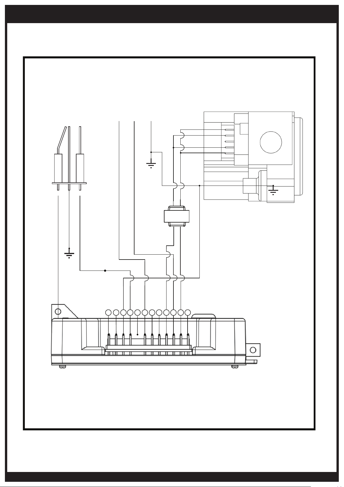
WIRING DIAGRAM
ELECTRICAL DIAGRAM
SEE INSTRUCTION MANUAL FOR DETAILS ON HOW
TO CONNECT THE ELECTRICAL COMPONENTS.
Ignition &
Ionisation
Green+Yellow
Black
Orange
Orange
White
Red 110 V
NL E
Blue
Green+
Yellow
Grand Mate Gas Valve
240 V
Transformer
110 V
6 5 4
Black
Blue
3
Purple
1
2
Yellow
12 11
Green+
10 9
White
8
Red
7
Control
Note:
If any of the original wire as supplied with the heater must be replaced, it must be replaced with 18AWG, 90ºC type UL
approved wire or its equivalent. If Transformer must be replaced, a UL approved model of similar type must be used.
Field wiring having a minimum temperature rating of at least 105°C shall be used and supply circuit wiring shall have a
minimum size of 18AWG.
www.bromic.com/heating
13
Page 14
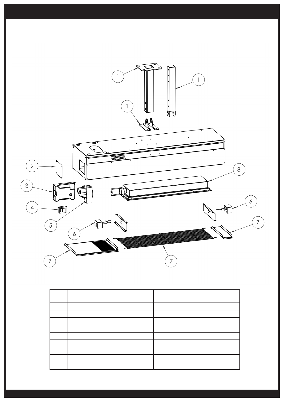
REPLACEMENT PARTS
14
No. Description Part No.
1 Mounting Bracket Set BHXXXXXXX
2 Control Cover Plate BHXXXXXXX
3 Control BHXXXXXXX
4 Transformer BHXXXXXXX
5 Gas Valve BHXXXXXXX
6 Wiring Harness BHXXXXXXX
7 Front Cover Set BHXXXXXXX
8 Burner BHXXXXXXX
9 Internal Gas Hose BHXXXXXXX
www.bromic.com/heating
Page 15
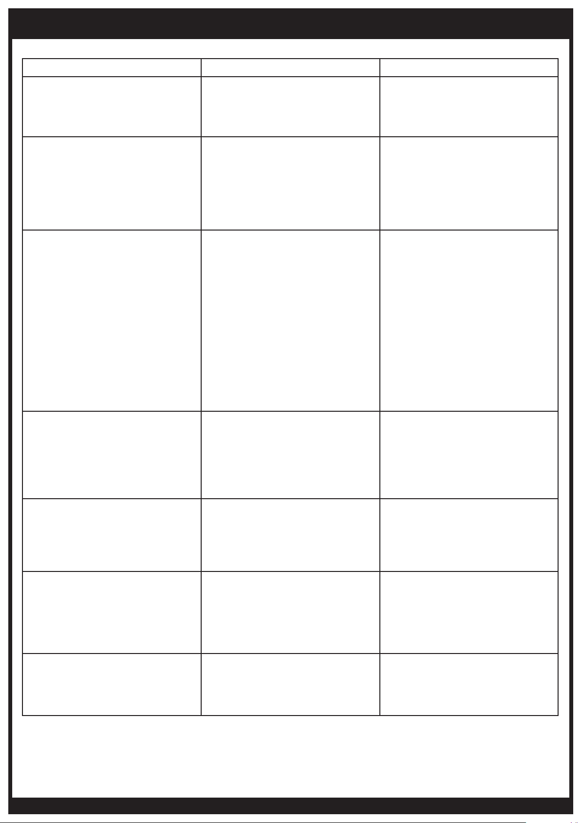
TROUBLESHOOTING
SYMPTOM POSSIBLE CAUSE CORRECTIVE ACTION
1. Have authorized electrician check
Heater will not turn on
Heater turns on, but then cycles on
and off
Low ceramic tile surface temperature
1. No power
2. No gas
1. Insufficient flame on ionisation rod
2. Drafty conditions
3. Insufficient earth connection
between heater and control box
1. Low manifold gas pressure
2. Low gas inlet pressure
3. Orifice partially blocked with
foreign matter
4. Combustion by-products not
adequately ventilated
5. Manifold misaligned fr om
excessive torque applied on pipe
at installation
6. Gas supply piping too small
7. Foreign matter in venturi tube
power supply
2. Have authorized gas fitter check
gas supply
1. • Check and set gas pressure
• Check and clear obstruction to
burner venturi and injectors
2. Discontinue use in high winds
3. Replace wiring harness and clean
connections to ensure good
grounding
1. Adjust valve regulator until 5”W.A
for natural gas, or 11” W.A for
propane is obtained
2. Adjust main supply regulator until
at least 6” W.C for natural gas or
11” W.C for propane precedes
heater’s control assembly
3. Clean orifice
4. Provide adequate ventilation of
by-products
5. Replace manifold
6. Increase gas pressure or replace
piping
7. Remove with bottle brush
1. Loose pipe connection
2. Defective regulator
Gas odour
Burning of gas/air mixture inside
burner casting (flashback)
Control assembly is overheating 1. Heater not mounted correctly
Carbon formation on ceramic tile
surface of burner
3. Defective manual shut-off valve
4. Defective gas control valve
5. Loose flexible hose
1. Separation of ceramic tiles
2. Ceramic tile(s) cracked
3. Heater mounted at incorrect angle
4. Excessive drafts
1. Misaligned orifice
2. Obstruction in venturi tube
3. Low gas pressure
4. Wrong gas supplied to heater
1. Check all connections with soap
solution and tighten where
necessary
2. Replace regulator
3. Replace manual shut-off valve
4. Replace gas control valve
5. Tighten flexible hose
1. Replace burner assembly
2. Replace burner assembly
3. Check angle of heater. See heater
nameplate.
4. Shield or relocate heater.
1. Mount wall bracket/control
housing against a vertical flat
surface, following the instructions
outlined in the installation section
of this manual. Always use
supplied parts to mount heater.
1. Consult sales agent or factory
2. Clean with bottle brush
3. Provide required pressure
4. Check label for type of gas
required
www.bromic.com/heating
15
Page 16
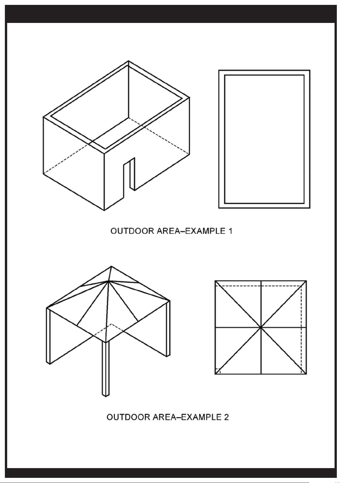
APPENDIX A
16
www.bromic.com/heating
Page 17
APPENDIX A CONTINUED...
www.bromic.com/heating
17
 Loading...