

Page 1
USER’S GUIDE
Go to Contents
www.broderbund.com
380865-MAN/I031kg
Page 2

© 2001 TLC Productivity Properties LLC, and its licensors and Advanced Relational
Technologies. A portion of texture files © 1989-01 IMAGETECTS™. All rights reserved. 3D
Home Architect is a registered trademark and Broderbund and the Broderbund logo are
trademarks of TLC Productivity Properties LLC. ImageCELs
®
is a registered trademark of
IMAGETECTS™. Windows and Windows NT are either registered trademarks or trademarks
of Microsoft Corporation in the United States and/or other countries. All other trademarks
are the property of their respective owners.
In the interest of product improvement, information and specifications represented here are
subject to change without notice.
Page 3

Table of Contents
Table of Contents (Click on a topic to go to that section)
Preface ...........................................................................................................................v
Chapter 1: Getting Started with 3D Home Architect Deluxe................................1
What’s in the Box.........................................................................................................2
System Requirements...................................................................................................2
Installing 3D Home Architect Deluxe............................................................................3
Starting 3D Home Architect Deluxe .............................................................................3
Removing 3D Home Architect Deluxe..........................................................................4
Chapter 2: An Overview of 3D Home Architect Deluxe.........................................5
What 3D Home Architect Deluxe Does.........................................................................6
What 3D Home Architect Deluxe Doesn’t Do...............................................................6
Using the Build House Wizard ......................................................................................7
Getting Around 3D Home Architect Deluxe .................................................................8
Windows ..................................................................................................................8
Views........................................................................................................................8
Modes....................................................................................................................13
Menu Commands ..................................................................................................13
Toolbar...................................................................................................................14
Understanding Objects...............................................................................................15
Manipulating Objects.............................................................................................15
Drawing a Plan...........................................................................................................17
Adding Walls ..........................................................................................................17
Adding Doors.........................................................................................................17
Adding Windows....................................................................................................18
Adding Cabinets.....................................................................................................18
Working with Fixtures, Furniture, and Outdoor Objects .........................................18
Working with Roofs................................................................................................19
Working with Electrical Outlets...............................................................................19
Understanding Default Settings..................................................................................19
Dealing with Multiple Floors ......................................................................................19
Understanding Text....................................................................................................19
Understanding Dimensions ........................................................................................20
i
Page 4

Chapter 3: Cabin Design Tutorial ............................................................................21
Getting Started ..........................................................................................................22
Removing All Plans from Memory ..........................................................................22
Using the Default Modes........................................................................................23
Drawing Walls ............................................................................................................24
Creating Dimension Lines.......................................................................................26
Naming Rooms ..........................................................................................................28
Placing Doors and Windows.......................................................................................30
Placing Cabinets.........................................................................................................33
Placing Fixtures ..........................................................................................................35
Adding a Window Above the Sink..........................................................................38
Working in Three Dimensions.....................................................................................39
Editing in 3D Views................................................................................................42
Placing Furniture ........................................................................................................43
Adding a Bathroom....................................................................................................45
Adding Bathroom Fixtures......................................................................................47
Applying Materials .....................................................................................................50
Adding Landscaping...................................................................................................51
Adding a Roof ............................................................................................................53
Adding Electrical Items...............................................................................................57
Adding Outdoor Images.............................................................................................57
Checking for Design Errors.........................................................................................59
Creating a Materials List.............................................................................................60
Chapter 4: Basic Techniques Tutorial......................................................................61
Planning a Project ......................................................................................................63
Getting Started ..........................................................................................................63
Creating the Exterior of a House ................................................................................63
Selecting Material for Exterior Walls .......................................................................66
Drawing Interior Walls................................................................................................66
Using Invisible Walls to Create an Open Plan .........................................................67
Using Wide Doorways to Create an Open Plan.......................................................69
Naming Rooms ......................................................................................................69
Placing Doors.............................................................................................................70
Creating the Front Door.........................................................................................71
Creating Interior Doors...........................................................................................71
Placing Windows........................................................................................................74
Using the Window Specification Dialog Box...........................................................76
Using the Copy Tool to Copy the Changes ............................................................77
Placing Special Windows ........................................................................................78
Cleaning Up the Display.............................................................................................80
ii
Page 5

: Table of Contents
Placing Cabinets.........................................................................................................81
Adding Cabinets.....................................................................................................83
Creating Cabinet Soffits..........................................................................................84
Creating an Island with Cabinets............................................................................85
Placing Fixtures ..........................................................................................................87
Adding Fixed Fixtures.............................................................................................87
Adding Movable Fixtures........................................................................................88
Looking at a Room.....................................................................................................89
Placing Furniture ........................................................................................................94
Selecting Colors and Materials for Furniture...........................................................94
Placing Fireplaces .......................................................................................................95
Building Decks and Porches........................................................................................98
Creating a Porch ..................................................................................................100
Creating Stairs..........................................................................................................101
Creating an Interior Staircase ...............................................................................101
Fixing Staircase Problems .....................................................................................104
Creating an Exterior Staircase...............................................................................106
Adding Additional Floors..........................................................................................109
Using Reference Plans...........................................................................................111
Showing the Second Floor View of the Staircase ..................................................113
Fine-Tuning Rooms...................................................................................................114
Adding Colors ......................................................................................................115
Getting Wired ..........................................................................................................116
Making a List and Checking It Twice........................................................................120
Using Plan Check .................................................................................................120
Checking the Budget ...........................................................................................121
Making Your Plan a Reality ...................................................................................122
Creating a 3D Walkthrough .....................................................................................122
Chapter 5: Advanced Roofing Techniques Tutorial ............................................123
Hip Roof...................................................................................................................124
Gable Roof ...............................................................................................................126
Shed Roof ................................................................................................................127
Saltbox Roof.............................................................................................................128
Gambrel Roof...........................................................................................................129
Gull Wing Roof.........................................................................................................130
Half Hip Roof............................................................................................................131
Mansard Roof...........................................................................................................132
Roof Type Quick Reference.......................................................................................133
Gables over Doors and Windows..............................................................................134
Placing Dormers in a Gable Roof..........................................................................134
Using the Break Wall Tool with Automatic Roof Designer.........................................139
iii
Page 6

Chapter 6: Reference: Toolbar Commands ..........................................................143
Mode Buttons ......................................................................................................144
Dialog Box Buttons ..............................................................................................144
Tool Selection Buttons..........................................................................................144
Tool Button Descriptions ......................................................................................144
Chapter 7: Reference: Menus.................................................................................167
File Menu.............................................................................................................168
Edit Menu ............................................................................................................177
Build Menu ..........................................................................................................179
Wall Submenu.................................................................................................179
Door Submenu ...............................................................................................188
Window Submenu ..........................................................................................195
New Floor Command .....................................................................................204
Foundation Command....................................................................................205
Roof Submenu ................................................................................................206
Stairs Command .............................................................................................208
Cabinet Submenu...........................................................................................214
Fireplace Command........................................................................................221
Electrical Submenu..........................................................................................224
Fixtures Command..........................................................................................228
Furniture Command........................................................................................231
Dimension Lines Submenu..............................................................................232
Text Command...............................................................................................234
Outdoor Objects Command ...........................................................................236
Outdoor Images Command............................................................................238
Ground Covering Command ..........................................................................239
Build Lot Command........................................................................................240
About Rooms .......................................................................................................241
Options Menu......................................................................................................247
3D Menu..............................................................................................................259
Tools Menu ..........................................................................................................265
Internet Menu......................................................................................................270
Window Menu .....................................................................................................270
Help Menu...........................................................................................................271
Appendix...................................................................................................................273
Appendix A: Introduction to Residential Design .......................................................274
Appendix B: Questions and Answers ........................................................................279
Contacting Technical Support ..............................................................................281
Appendix C: Printing Blueprints ...............................................................................282
Index ..........................................................................................................................285
iv
Page 7

Preface
Congratulations on your purchase of 3D Home Architect®Deluxe 4, the complete software
solution for easy home design. With 3D Home Architect Deluxe 4, you can quickly and easily
produce accurate and complete floor plans for a remodel, an addition, or even an entire
home. The program will handle multiple floors, check your design for obvious errors,
determine the building materials you need, and let you see and work with your design in
three dimensions. The program automatically lines up walls, measures and adds dimensions,
and does most of the other tedious work necessary to create building plans. It frees you to
do the creative work.
About This Manual
The Getting Started chapter covers hardware and software requirements, and installation.
The Overview shows you around the program and introduces basic concepts.
The Cabin Tutorial takes you through the creation of a basic plan. You will learn to edit a
plan in different views. Finally, you will see how to use special features like automatic
dimensions, electrical outlet placement, Plan Check and how to create a Materials List for
estimating cost.
The Basic Techniques Tutorial shows you how to create staircases, custom windows, cabinetry,
decks, and multiple stories.
The Advanced Roofing Techniques Tutorial teaches you how to build eight different roof
structures. You can combine any of these styles to create your own custom roofs. This
chapter also introduces two tools that help in the roof creation process, and includes an
introduction to placing dormers in your roof.
The Reference provides an item-by-item explanation of each program feature, organized by
the toolbar and menus.
The Introduction to Residential Design provides a brief overview of the aspects of residential
building design relevant to the home architect.
At the end of the manual you will find answers to common questions and information on
contacting Technical Support.
A Word about Windows
This manual assumes you are familiar with Windows and basic Windows techniques, such as
using the mouse and menus. If you are new to computers, or unfamiliar with Windows,
consult the Microsoft Windows documentation.
®
v
Page 8

vi
Page 9
Chapter
1
Getting Started with 3D Home
Architect®Deluxe 4
1
Page 10

This chapter walks you through setting up the program. You’ll learn:
• What’s in the box
• System requirements
• How to install the program
• How to start the program
• How to remove the program
What’s in the Box
Your 3D Home Architect®Deluxe 4 package should include the following:
• 3D Home Architecture Deluxe 4 Program CD-ROM
• Home Styles 1500 Best-Selling Home Plans
• User’s Manual
• Registration Card
System Requirements
To install and run 3D Home Architect Deluxe 4, your system must include the following:
• 100% IBM-compatible computer with a 166MHz processor or better (300MHz
recommended).
• Windows 95B/C, Windows NT 4.0 (Service Pack 3 or higher), Windows 98, Windows
2000 or Windows Me (Millennium Edition).
• 150MB free of hard-disk space.
• 32MB of RAM (64MB recommended). 64MB minimum for Windows NT.
• CD-ROM Drive.
• Two-button mouse supported by Windows.
• Color VGA, SuperVGA, or higher-resolution monitor that supports 256 colors. (We highly
recommend a video card that supports OpenGL and hardware acceleration.)
Optional:
• Printer
• 14.4 Kbps modem for Internet access*
• 19.5MB free hard-disk space for AT&T WorldNet
User is responsible for all Internet access fees and phone charges.
®
Service software installation
2
Page 11

Chapter 1: Getting Started with 3D Home Architect®Deluxe 4
Installing 3D Home Architect Deluxe 4
These instructions assume you are at the Windows®desktop.
To install
1. Insert the CD-ROM into your CD drive.
The 3D Home Architect Deluxe 4 startup window appears. If it doesn’t, use the steps
below these to install the program manually.
2. Click the Install button.
3. Follow the on-screen instructions to install the program.
To install manually
If the 3D Home Architect Deluxe 4 startup window doesn’t appear automatically, use these
steps to install the program manually.
1. Insert the CD-ROM into your CD drive.
2. Click the Start button on the taskbar and choose Run.
3. Type D:\LAUNCHER.EXE in the line labeled Open.
If your CD drive uses a letter other than D, substitute that letter for D.
4. Click OK and follow the on-screen instructions to install 3D Home Architect Deluxe 4.
Starting 3D Home Architect Deluxe 4
You can run 3D Home Architect Deluxe 4 from its startup window or from the Start button
on your Windows desktop.
To run 3D Home Architect Deluxe 4 from its startup window
1. After successfully installing the program, insert the 3D Home Architect Deluxe 4 CD-ROM
into the CD drive.
2. Click the Run button on the 3D Home Architect Deluxe 4 startup window.
If the 3D Home Architect Deluxe 4 startup window does not appear, you can run the
program from the Windows desktop.
To run 3D Home Architect Deluxe 4 from the desktop
1. Insert the 3D Home Architect Deluxe 4 CD-ROM into the CD drive.
2. Click the Start button.
3. Point to Programs, and then to 3D Home Architect Deluxe 4.
4. Click the 3D Home Architect Deluxe 4 menu item to start the program.
3
Page 12

Removing 3D Home Architect Deluxe 4
If you need to remove 3D Home Architect Deluxe 4, begin at the Windows®desktop.
To remove 3D Home Architect Deluxe 4
1. Click the Start button on your Windows desktop.
2. Point to Programs, then to 3D Home Architect Deluxe 4.
3. Click Uninstall 3D Home Architect menu item to uninstall the program.
Starting Homestyles 1500 Best-Selling Home Plans
To Install:
1. Insert the HomeStyles 1500 Best-Selling Home Plans CD-ROM into your CD drive.
2. Click the Start button on the task bar and choose Run.
3. Type D:/SETUP.EXE in the line labeled Open.
If your CD drive uses a letter other than D, substitute that letter for D.
4. Click OK and follow the on-screen instructions to install Homestyles 1500 Best-Selling
Home Plans.
You can run the Homestyles 1500 Best-Selling Home Plans from the shortcut icon on your
desktop, or from the Windows Start button.
To start the Homestyles 1500 Best-Selling Home Plans from your desktop.
Note: After successfully installing the Homestyles 1500 Best-Selling Home Plans
CD a shortcut icon will be automatically installed to your desktop.
1. Insert the Homestyles 1500 Best-Selling CD-ROM into the CD drive.
2. Double click the Homestyles 1500 Best-Selling Home Plans icon on your desktop to
start the program.
To start the Homestyles 1500 Best-Selling Home Plans from the Windows Start button.
1. Insert the Homestyles 1500 Best-Selling Home Plans CD-ROM into the CD drive
2. Click the Windows
3. Point to Programs, 1500 Best-Selling Home Plans, and then to 1500 Best-Selling
Home Plans.
4. Click the 1500 Best-Selling Home Plans menu item to start the program.
®
Start button
4
Page 13
Chapter
An Overview of 3D Home
Architect®Deluxe
2
5
Page 14

This chapter gives you an overview of the program. You’ll learn:
®
• What 3D Home Architect
• How to use the Build House Wizard
• How to use the windows, views, modes, menus, and tools in the program
• How to work with 3D Home Architect Deluxe 4 objects
• How to work with multiple floors
• How to use text
• How to use dimensions
Deluxe 4 does and doesn’t do
What 3D Home Architect Deluxe 4 Does
3D Home Architect Deluxe 4 creates complete, professional-looking residential floor plans. The
program simplifies the task of accurately drawing plans, letting you experiment with possible
alternatives and convey your ideas to others.
Using 3D Home Architect Deluxe 4, you can:
• View and edit your plan in three dimensions.
• Record and show walkthroughs (animated 3D representations) of your house.
• Add exterior landscaping objects like trees, shrubs, and flowers.
• Start your plan with an existing one, and then modify it for your needs.
• Create accurate dimensions and other details automatically.
• Create itemized lists of materials to help you estimate material costs.
• Print your plan to any scale as a floor plan, a 3D view, or an interior elevation.
• Check your plans for compliance with certain building standards and rules.
• Experiment with how you want your home to look, without agonizing over every line and
measurement.
What 3D Home Architect Deluxe 4 Doesn’t Do
3D Home Architect Deluxe 4 cannot determine the building codes and practices for your area,
so consult a licensed contractor to see what works and what is required.
This program assumes standard construction techniques. For designs that require specialized
construction, like multiple-story homes on steep sites, consult professional architects and
builders.
3D Home Architect Deluxe 4 cannot design your home for you, but it frees you to experiment
with different design ideas. You must decide room size and location, and how light, air, and
people will move about within your home. Study different designs, try them out, and think
about how you and your family will really live in and use the home you design.
6
Page 15
Chapter 2: An Overview of 3D Home Architect Deluxe 4
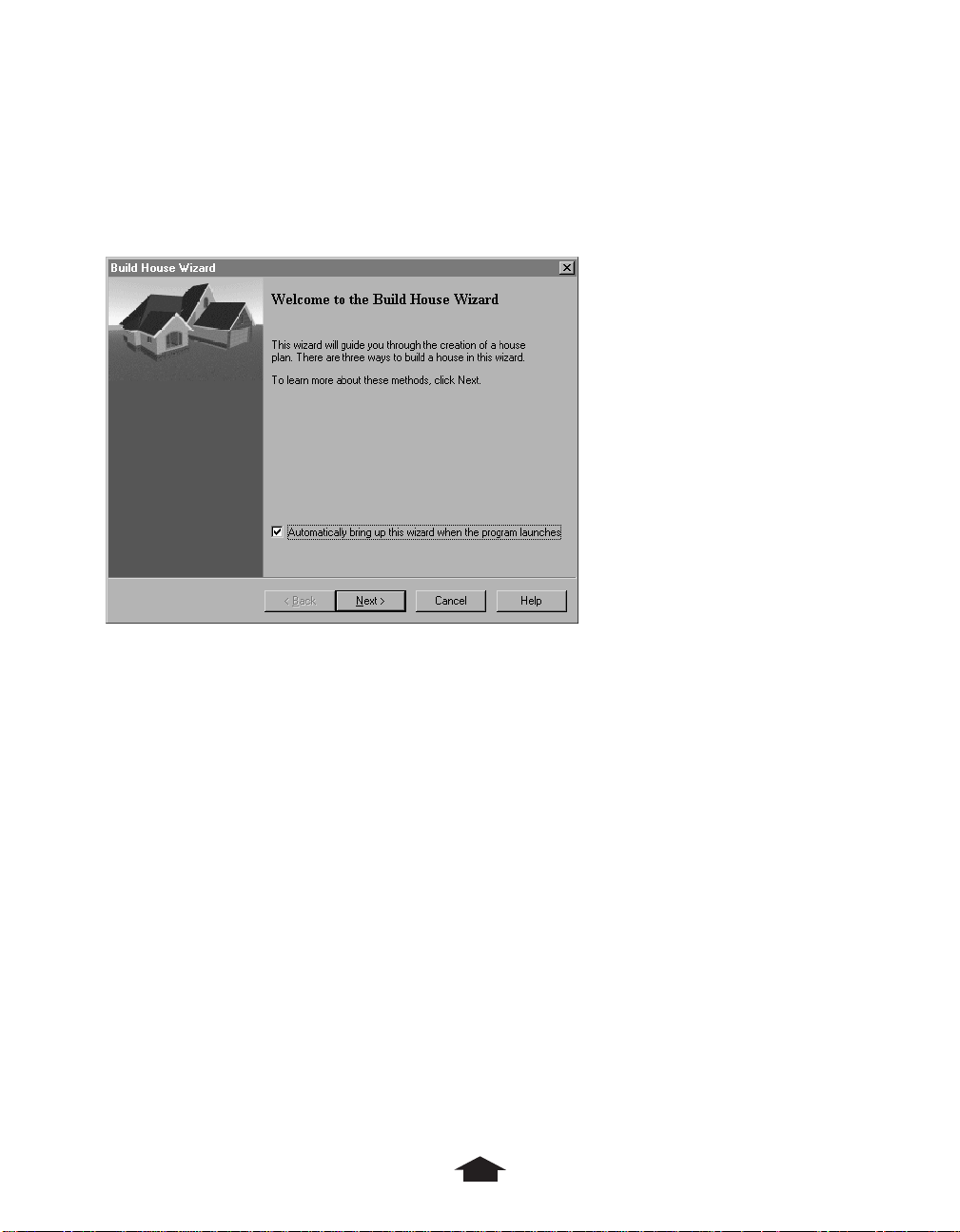
Using the Build House Wizard
The Build House Wizard is a shortcut to starting a new plan. When you first start 3D Home
Architect Deluxe 4, the wizard displays:
Build House Wizard
If you don’t want the wizard to display in the future, clear the Automatically bring up this
wizard when the program launches check box. You can still run the wizard by choosing
House Wizard on the Tools menu.
The Build House Wizard has three options:
• You can start with a sample plan and modify it for your needs.
The wizard prompts you for the style and size house you want, and then displays a list of
plans that match your criteria. You can see a preview of each sample plan and choose one
to start with. When you click Finish, the wizard displays the sample plan so you can edit
it.
• You can have the wizard generate rooms that you arrange to form your house.
The wizard prompts you for the number of floors you want, and whether you want
features like a garage, deck, porch, or laundry room. You specify which kinds of rooms
you want on the first floor. When you click Finish, the wizard creates a box for each room
you requested. You arrange the rooms, and then re-run the wizard from the Tools menu
to specify the remaining floors.
• You can use the Wall tool to define your plan manually.
This option bypasses the wizard and lets you build a plan manually. Manual techniques
are covered in detail in the tutorials and reference chapters.
7
Page 16
Getting Around 3D Home Architect®Deluxe 4
3D Home Architect Deluxe 4 uses multiple application windows to display different views of
your plan. All the menus and commands in the program are available via the toolbar or
menu.
Windows
3D Home Architect Deluxe 4 displays multiple, independent application windows, so you can
have several views of a single plan open at once (for example, Plan, Cross Section/
Elevation, and Camera views), plus several versions of each view (for example, Camera
views from two angles), and even several different plans (to compare designs).
Views
Views in 3D Home Architect Deluxe 4 are different ways of looking at your design: each shows
a different aspect of your design, each has a different use, and each is displayed in a
different window. You can move, resize, open, close, and print each window separately. To
make a window active, click it. You can open a maximum of ten windows at any given time.
You can change, add objects, and change walls only in the Plan window. Once you’ve
added an object, you can change it in any window but Materials. You can resize objects
only in Cross-Section/Elevation view. All views except Materials reflect changes in other
windows.
Views are available via the View Mode button or the commands on the 3D menu.
View Mode button
View Mode options
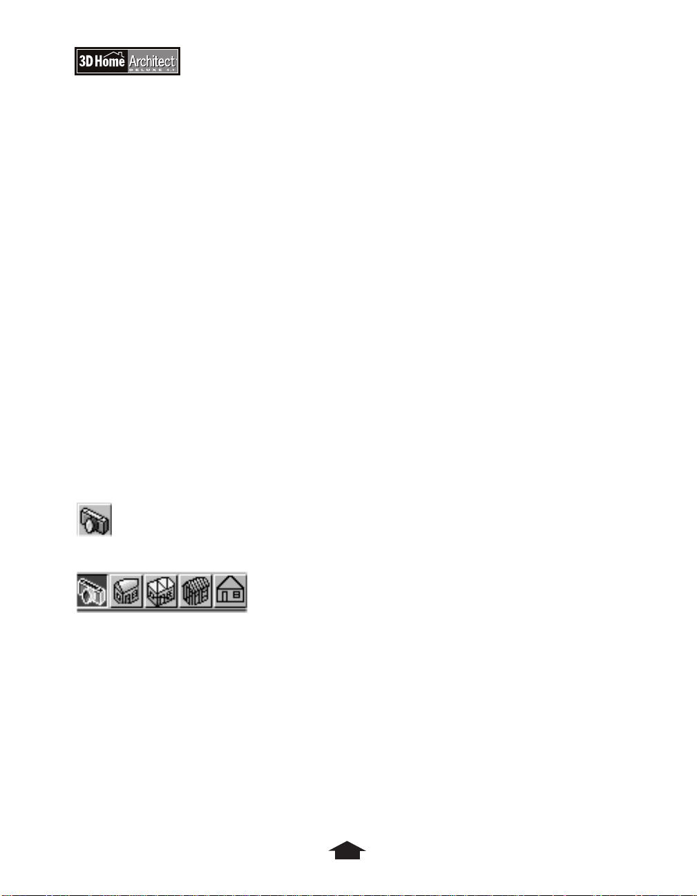
Plan View
Most views are opened from Plan view, which is the view displayed when you first open
a file.
Plan view shows you a two-dimensional blueprint view of your design. Here you can add,
edit, and see all the elements of your plan, from walls and doors to furniture, dimensions,
and labels.
8
Page 17
Chapter 2: An Overview of 3D Home Architect Deluxe 4
Plan View
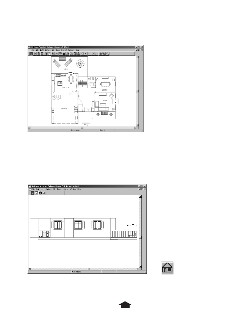
Cross Section/Elevation View
Cross Section/Elevation view shows a cross-section view of your design, including roofs,
but of the vertical plane so it shows width and height.
Although you cannot add objects or change walls in this view, you can change objects like
doors, windows, cabinets, and furniture. This view lets you line up objects precisely, because
you can see them straight on and view their height relative to one another.
Cross Section/Elevation View Cross Section/Elevation tool
9
Page 18
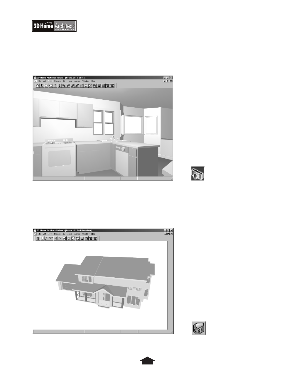
Camera View
Camera view shows a three-dimensional perspective of the interior of your design. Camera
view shows you how the plan will look when finished, complete with fixtures and furniture.
Camera View Camera tool
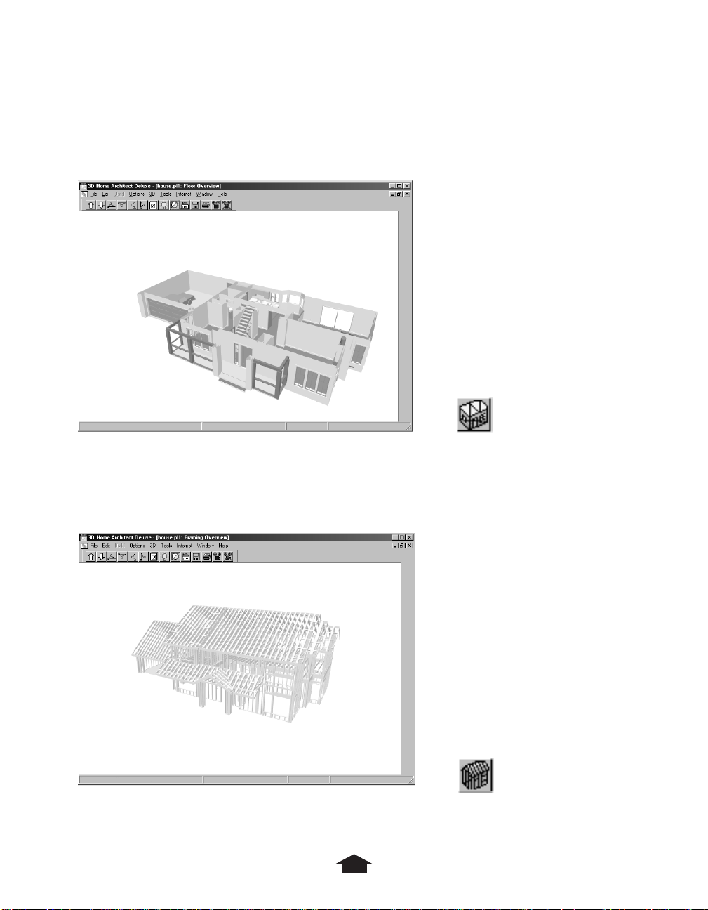
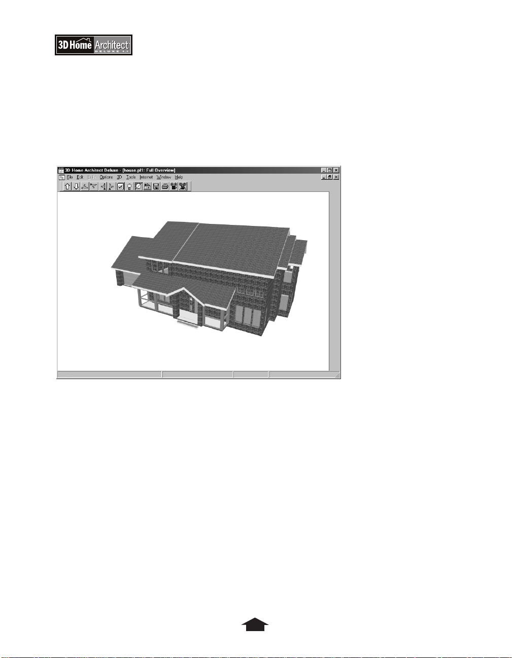
Full Overview
Full Overview shows a bird’s-eye view of the entire plan, including multiple-level designs
with roofs.
Full Overview Full Overview tool
10
Page 19
Chapter 2: An Overview of 3D Home Architect Deluxe 4
Floor Overview
Floor Overview opens a three-dimensional, bird’s-eye view of the entire plan, including
multiple level designs. No roofs display.
Floor Overview Floor Overview tool
Framing Overview
Framing Overview displays only the frames, studs, and walls that comprise your plan.
Framing Overview Framing Overview tool
11
Page 20
Final View
Final View is available from the 3D menu and from the toolbars in the Camera and Full
Overview views. The Final View shows you the same views as the Camera view, but it
smoothes out textures and makes sure they are accurate where different planes meet (for
example, where a countertop meets the wall). You can save this view as a bitmap graphic
image.
Final View
12
Page 21
Chapter 2: An Overview of 3D Home Architect Deluxe 4
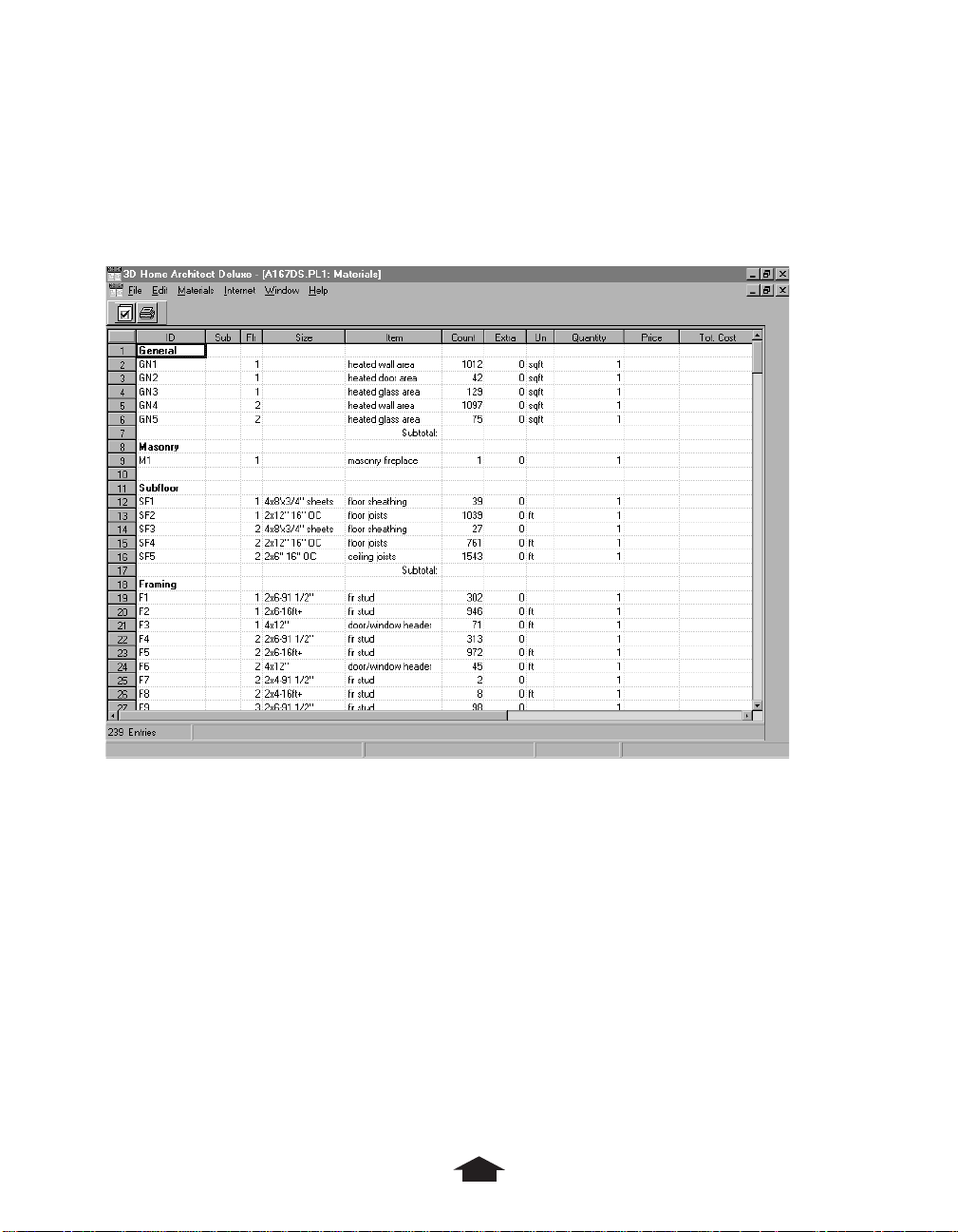
Materials
The Materials window is available from the Options menu. The Materials window shows a
list of the materials needed to construct your plan. You can also use the Materials window
to generate a cost of materials based on unit costs that you enter.
Materials Window
Modes
Modes let the program create objects or carry out commands, like drawing walls, placing
windows, and changing views. You select a mode, and then you select a tool within that
mode, and then you execute a command by clicking the tool.
For instance, to build a wall, first you select Wall from the Build menu, and then you select
a type of wall (for example, Beam), and then you click and drag to create a beam in your
plan.
Menu Commands
All commands in 3D Home Architect® Deluxe 4 are available from its menus. To display a
menu, click its title. For a complete discussion of the menus, see the Reference chapter.
13
Page 22
Toolbar
The toolbar provides shortcuts to the most commonly used commands. You can use the
toolbar for most of your work. However, there are commands and options available in the
menus for which there are no toolbar equivalents.
Each toolbar button represents one command. For example, the Wall command on the
Build menu is equivalent to the Wall button.
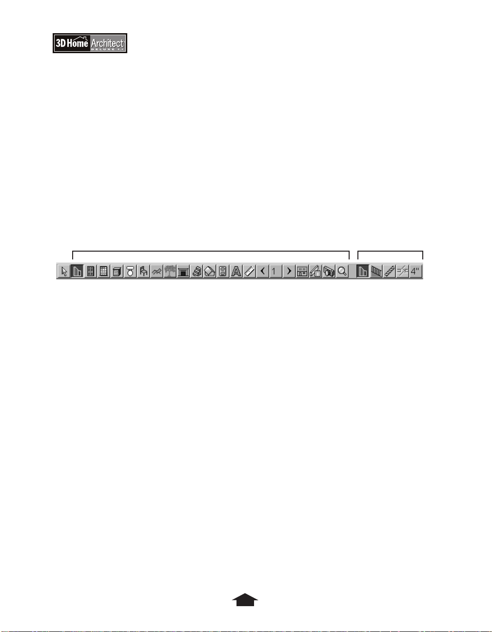
Mode buttons are on the left side of the toolbar and tool buttons are on the right side.
When you press a mode button on the left side, the tool buttons for that mode are
displayed on the right. The first tool button is depressed by default, since it is the most
commonly used. For example, when you click the Wall Mode button, the Wall tool is
automatically selected and you can begin to draw standard walls.
Mode Buttons Tool Buttons
Toolbar
When the pointer passes over a button, its name pops up in a small window called a tooltip.
The toolbar changes as you make different windows active, reflecting what you can do in
each window.
The toolbar includes buttons for Fixtures, Furniture, Outdoor Objects, Outdoor Images,
and Stairs. These tools display dialog boxes where you can choose items to place in your
plan.
The Fireplace, Text, and Stairs tools let you click in the Plan window to add a fireplace,
text, or stairs.
For a full description of all toolbar options, see the Reference chapter.
14
Page 23
Chapter 2: An Overview of 3D Home Architect Deluxe 4
Understanding Objects
Most CAD and general-purpose drawing programs create simple geometric objects like lines
and arcs, and then associate these to each other to create more complex entities. This
program uses objects that include information on how they are shaped, what they are, how
they relate to other objects, and what they can do.
Instead of carefully drawing lines and calling them walls, you just click and drag a wall.
When you connect this wall to other walls, or add doors and windows to it, or attach
cabinets, the program recognizes the objects you are using and what you are doing and
responds accordingly. Much of your drawing is done automatically; you do not have to
position and size things exactly. The program warns you when you are breaking the rules.
You spend less time drawing and more time designing.
Manipulating Objects
Once you place an object in your plan, you click it to change it in different ways.
Using Handles
Walls, text, and outdoor images display three squares, called handles. There is one handle at
each end and one in the middle. Other objects, like cabinets and furniture, have at least two
handles: a triangle on one end and a square in the middle. Cabinets display four squares, a
triangle, and an arrow. The arrow indicates which way the cabinet is facing.
Cabinet selected
To move an object
1. Click the object to select it.
2. Move the pointer over the middle or square handle to change the arrow pointer to
double-sided arrows.
3. Drag the pointer to move the object.
Objects with a square and triangle can be moved only vertically and horizontally. To
move objects freely, hold down the Ctrl key and drag.
15
Page 24
To resize an object
• Drag one of the end handles in or out.
To rotate an object
1. Move the pointer over a triangle handle to change the arrow pointer to a circling arrow.
2. Drag to rotate the object.
Selecting, Copying,and Deleting Objects
You can select single and stacked objects, open a dialog box to change the object, and copy
or delete objects.
To select an object
• Click the Select Items button on the toolbar, or Select Items on the Edit menu.
Select Items button
This switches the program to Select Items. When you select an object, as many as four
right-hand tools will appear in the toolbar, depending on the type of object selected: the
Next, Open, Copy, and Delete tools.
To select a stacked object
1. Select the object.
2. Click the Next tool.
Next tool
The Next tool lets you select items that are stacked, like staircases, or incorporated into
other objects, like standard windows within bay and bow window structures.
To change an object
1. Select the object.
To select a room, click inside it anywhere except on an object; the room will then be
outlined.
2. Click the Open tool or double-click the object.
Open tool
You can open almost every item in your plan in almost every view.
16
Page 25
Chapter 2: An Overview of 3D Home Architect Deluxe 4
To copy an object
1. Select the object.
2. Click the Copy tool.
Copy tool
The pointer changes to a Copy pointer.
3. Click to place the copy.
To delete an object
• Use the Delete command on the Edit menu, the Delete key, or the Delete tool.
Delete tool
Drawing a Plan
There are three things to remember when drawing a plan:
• You define the rooms in your plan with walls. If a space is not completely surrounded by
walls, it is not a separate space.
• Openings in walls are best made by placing doors in the walls, and not by leaving out a
section of wall.
• The program will measure and align walls for you, and will even move and resize walls to
make them connect. You can sketch out the general shape first, and fine-tune later.
Adding Walls
You create walls using the Wall mode tools in the toolbar or by selecting the Wall
commands on the Build menu. The tutorials and the Reference chapter provide detailed
information about walls.
Adding Doors
Doors, like windows, are openings in walls that you create by selecting the appropriate
command or tool, and then clicking the area of the wall where you want the opening.
Once you place the door, you can change it by moving and resizing or opening it to change
its specifications. The tutorials and the Reference chapter provide detailed information about
doors.
17
Page 26
Adding Windows
You create windows using Window mode and commands. Select the kind of window you
want and click where you want it.
You can change the width of a window, and adjust its height. The tutorials and the Reference
chapter provide detailed information about windows.
Adding Cabinets
You can place a cabinet anywhere in a plan where there is room for it. If you click a Cabinet
tool near a wall, the cabinet automatically attaches to that wall.
Cabinets are considered modules that fit together, so when you create several in a row they
seem to join into one. As modules, they are also a standard size (which you can set and
change).
The size of the cabinet, its orientation, and its type can change automatically depending on
where you put it. For example, if you place a cabinet in a corner, it automatically becomes a
corner cabinet.
The tutorials and the Reference chapter provide detailed information about cabinets.
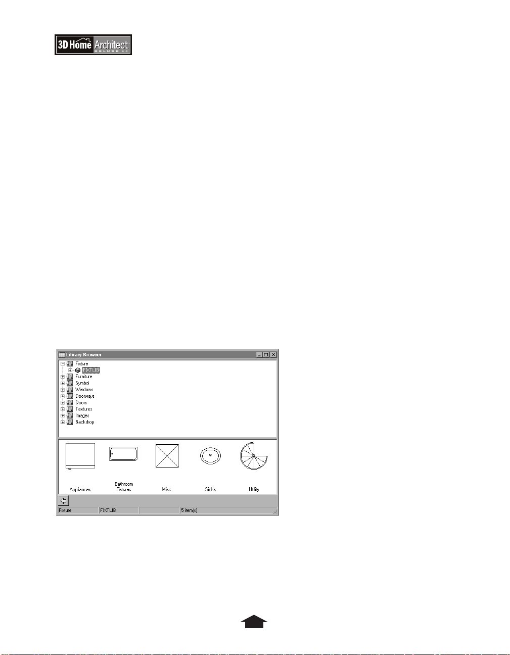
Working with Fixtures, Furniture, and Outdoor Objects
The Library Browser lets you find and place fixtures, furniture, and outdoor objects.
Library Browser
Some fixtures, like sinks, are placed in cabinets. You can place one fixture per cabinet, and
the fixture is always placed in the middle of the cabinet. Some fixtures, like refrigerators, are
freestanding. Fixtures placed in cabinets are edited with the cabinets, while freestanding
fixtures, furniture, and outdoor objects are edited individually.
18
Page 27

Chapter 2: An Overview of 3D Home Architect Deluxe 4
Working with Roofs
Create your roofs after you complete all other design aspects, but before you place electrical
items in the plan.
By using the appropriate roofing tools, you can add gables above doors and windows and
place dormers in the attic of your plan.
®
3D Home Architect
default is a hip roof, but you can modify this. Go through the Advanced Roofing Techniques
Tutorial to learn more about roofs.
Deluxe 4 uses Automatic Roof Designer to generate roof structures. The
Working with Electrical Outlets
You select and place electrical outlets (both 110V and 220V), switches, and light fixtures as
you do cabinets. You can’t see electrical items in 3D views and you can’t change their
specifications, but they are included in the Materials List.
Understanding Default Settings
For most object types, default settings are derived from the plan-wide defaults for that
object type. You set defaults for different types of items on the Defaults Setup submenu of
the Options menu.
Default values are useful because, in the case of windows, you usually want them to be the
same size. Initial values ensure that all windows are the same dimensions when first placed.
You can tweak them individually.
Dealing with Multiple Floors
3D Home Architect®Deluxe 4 can handle up to three separate floors in a plan, plus an attic
and a foundation, which is a special case.
You work on floors one at a time. However, you can superimpose one floor, called a
reference floor, on your current (working) floor to keep things lined up, and you can easily
swap the current and reference floors back and forth. See the section on the Tools menu in
the Reference chapter for more information.
Understanding Text
Text is drawn as an object, so it scales up or down as you zoom in or out of the plan. Text is
sized in plan inches, as in CAD programs, not in points, as in word processors.
19
Page 28

Understanding Dimensions
Dimension lines locate walls and openings in walls by showing how far one wall is from
another, or how far an opening is down a wall. You can create interior and exterior
dimension lines. Manual, interior dimension lines are built like walls.
Once created, dimension lines can be moved, but not resized. Their ends move
automatically when the associated walls move.
20
Page 29
Cabin Design Tutorial
Chapter
3
21
Page 30

Cabin Design Tutorial
This tutorial walks you through the design of a two-room cabin. You’ll learn how to:
• Draw walls
• Name rooms
• Place doors and windows
• Add fixtures and furniture
• Add a bathroom
• Apply materials to items in the plan
• Put in landscaping
• Add a roof
• Add electrical switches, outlets, and other items
• Check your plan
• Generate a materials list for the design
Getting Started
You should start the tutorial with a blank slate.
Removing All Plans from Memory
Start the program. Make sure no plans are open.
To start 3D Home Architect Deluxe 4
1. Click the Windows
2. Point to Programs.
3. Point to 3D Home Architect Deluxe 4.
4. Click the 3D Home Architect Deluxe 4 menu item to start the program.
®
Start button.
To close any open plans
1. On the File menu, click Close All.
Using the Close All command instead of Close removes all plans from memory.
2. On the File menu, click New.
22
Page 31

Using the Default Modes
A Plan view window opens, ready for you to start drawing.
Chapter 3: Cabin Design Tutorial
Empty Plan View window
When you start a new plan, Wall mode is the default mode, and the Wall tool is the default
tool. This means you can start drawing standard walls immediately.
Wall Mode button
Wall tool
23
Page 32

Drawing Walls
Start by making a wall approximately 20 feet in length. Don’t worry about being exact.
To draw a wall:
1. Move the pointer to the top left of the screen.
2. Click and drag out a wall to the right.
Plan with 20-foot wall
As you drag, the status box in the toolbar indicates how long the wall is. You can draw
angled walls, but the angle is restricted to increments of 15 degrees. This ensures that
parallel walls will be parallel, which is important if you export your plans to other CAD
programs. Also, your builders will thank you, because simple angles are easier to build.
3. Use the same technique to drag out another 20-foot wall, perpendicular to the first one,
on the right side.
You do not need to begin this wall exactly where the other wall ends—just get it close,
and the new wall will automatically snap to the existing wall.
24
Page 33

Chapter 3: Cabin Design Tutorial
4. When the second wall is finished, draw two more walls to make a box.
Plan with box drawn
If you make a mistake, draw over a wall again, or click the wall with the pointer, and then
press the Delete key. To start over, select Close from the File menu and then New.
To adjust the spacing of the walls
1. Click a wall.
You will see a dimension line stretching out to the opposite wall, and three handles: one
in the middle of the selected wall, and one at either end.
2. To move a wall, click the wall, and then drag its center handle outwards.
When you move a wall, the lengths of all connected walls are adjusted automatically,
keeping them connected. This makes it very easy to sketch out a rough design, which
you can adjust for precise dimensions later.
3. To resize a wall, click the wall, and then drag one of its end handles.
25
Page 34

Creating Dimension Lines
Dimension lines locate walls and openings in walls by showing how far one wall is from
another, or how far an opening is down a wall. You can add automatic exterior dimension
lines, as well as manual interior dimension lines.
To create dimension lines
1. Click the Dimension Mode button on the toolbar.
Dimension Mode button
Two additional tools are now available on the right side of the toolbar. The first tool
creates manual dimension lines. The second tool, the Exterior Dimension tool, creates
exterior dimension lines automatically.
2. Click the Exterior Dimension tool and see what happens.
Exterior Dimension tool
Plan with dimension lines
26
Page 35

Chapter 3: Cabin Design Tutorial
3. For a closer view, click the Zoom Mode button.
Zoom Mode button
4. Drag a box around the area you want to see in detail. The area fills the screen.
5. To return to the original view, click the Undo Zoom button.
Undo Zoom button
6. If you can’t see all the exterior dimension lines at once, click the Fill Window button.
Fill Window button
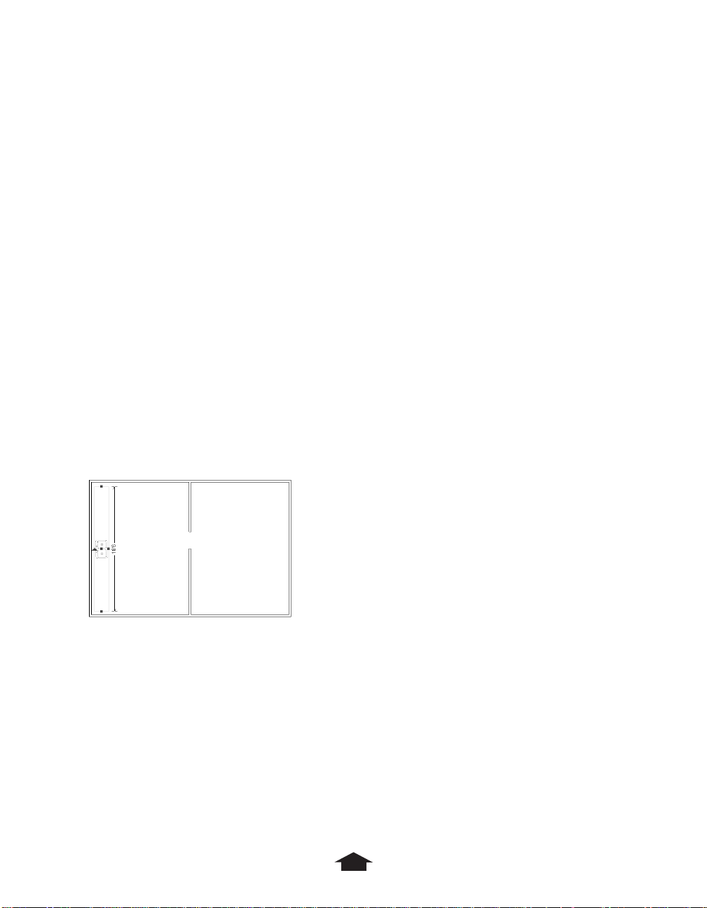
7. Divide the room into two rooms by drawing another wall within the enclosure, using the
Wall tool again.
The plan should look something like this:
Plan with two rooms
27
Page 36

Naming Rooms
Rooms in 3D Home Architect®Deluxe 4 have special qualities that are not available until they
are named.
To name your room
1. Click the Select Items button.
2. Double-click the room on the left.
The Room Specification dialog box appears.
Room Specification dialog box
3. Click the arrow next to Room Name.
4. In the list that appears, click Kitchen.
28
Page 37

Chapter 3: Cabin Design Tutorial
5. Click OK to leave the dialog box and return to the Plan view.
Plan with Kitchen labeled
6. Double-click the room on the right.
7. Select Bedroom in the Room Name list.
8. Click OK.
29
Page 38

Plan with both rooms labeled
Placing Doors and Windows
Now you’ll add some doors and windows to the cabin.
To add a door
1. Click the Door Mode button.
Door Mode button
A number of tools appear on the right side of the toolbar. They represent different types
of door commands. By default, the active tool is the Door tool.
Door tool
30
Page 39

Chapter 3: Cabin Design Tutorial
2. To put a standard door in the cabin, move the pointer to the bottom wall at the
midpoint of the bedroom and click.
A doorway is placed in the wall. No door appears in the doorway until you indicate
which way the door should open.
3. Click the doorway.
Three handles appear, just as they do when you click a wall.
4. Click an end handle, and then drag in the direction that you want the door to open.
5. Now place a doorway from the bedroom into the kitchen.
The plan should look like this:
Plan with two doorways
31
Page 40

To add a window
1. Click the Window Mode button to change to Window mode.
Window Mode button
As with Door mode, a number of tools appear on the right side of the toolbar that are
specific to Window mode. By default, the Window tool is active.
Window tool
The other tools let you place other types of windows, such as bay windows. You can also
use the Window Library button, which gives you an even wider assortment.
2. To place a standard window, click the top wall at the midpoint of the bedroom.
Plan with a window in the Bedroom
32
Page 41

Chapter 3: Cabin Design Tutorial
Placing Cabinets
Now you’ll place some cabinets.
To add a cabinet
1. Click the Cabinet Mode button.
Cabinet Mode button
Tools specific to cabinets appear on the right-hand side of the toolbar. These tools place
different types of cabinets: base cabinet, wall cabinet, full height cabinet, and shelving.
By default, the Base Cabinet tool is active.
Base Cabinet tool
2. Place some cabinets against the left wall in the kitchen.
3. If you put a cabinet in the wrong place, click it again to make it active and move it, or
delete it and start over.
Don’t worry about orienting the cabinets correctly. A cabinet automatically moves
against the wall with its front facing out when you place it near a wall. Also, when you
place cabinets next to each other, they attach to form an extended cabinet, since
cabinetry in a modern kitchen is made up of modular units linked together.
The arrow on the cabinet tells you which way the cabinet is facing.
4. To rotate a cabinet, click the Select Items button, and then click the cabinet. Click the
red arrow at the rear of the cabinet, and then drag in a circular motion.
5. Use the side and center handles to move and resize the cabinet.
By default, you can move a cabinet up, down, left, and right. To have unrestricted
movement, click the cabinet, press Ctrl, and then drag the cabinet.
33
Page 42

Your plan should now look like this:
Plan with cabinets placed in Kitchen
34
Page 43

Chapter 3: Cabin Design Tutorial
Placing Fixtures
You place some objects, such as sinks and some appliances, within cabinets. Add a sink to
one of your cabinets, and then add a dishwasher to a different cabinet.
To add a sink to a cabinet
1. Click the Fixtures Mode button.
Fixtures Mode button
The Library Browser appears.
Library Browser for Fixtures
2. Click the plus sign next to the item labeled Fixtures to see items in the Fixture Library.
3. Click the plus sign next to the item labeled Plumbing_3DHA
4. Click the plus sign next to the item labeled Sinks.
5. Click the plus sign next to Kitchen Sinks.
35
Page 44

6. Click 24" Single Kit. Sink.
Library Browser with 24" Single Kit. Sink selected
7. Double-click the picture of the sink in the bottom of the window.
The pointer is shaped like a toilet. This means you can place fixtures in the plan.
8. Click in the middle of the Kitchen, away from the cabinets.
A warning message tells you that you must place this fixture in a cabinet. The program
will not let you place the sink anywhere but in a cabinet.
9. Move the pointer over the cabinet that is closest to the center of the wall and click.
36
Page 45

A sink has appeared in the center of the cabinet.
Chapter 3: Cabin Design Tutorial
Plan with 24-inch sink placed in cabinet
To add a dishwasher to a different cabinet
1. Click the Fixtures Mode button.
You must click this button each time you want to place a different fixture.
2. A dishwasher is an appliance, so open Appliance_3DHA, and then open Kitchen.
3. Click Dishwasher, and then double-click its picture in the bottom of the window.
4. Click in the plan to place the dishwasher into a cabinet.
Make sure you don’t click the same cabinet where you placed the sink. If you do, the
dishwasher will replace the sink.
37
Page 46

Cabinets containing fixtures must be large enough to accommodate them. Create the
cabinet, adjust its size if necessary, and then place the fixture in it.
Plan with dishwasher placed in cabinet next to sink
Adding a Window Above the Sink
Now that you have a sink in your kitchen, add a window above it.
To add a window over the sink
1. Click the Window Mode button, as you did earlier.
Window Mode button
By default, the standard Window tool is active.
2. Click the wall above the cabinets and sink.
38
Page 47

A window appears above the sink.
Chapter 3: Cabin Design Tutorial
Plan with window placed above sink
Working in Three Dimensions
Take a look at the cabin in three dimensions.
To view the plan in three dimensions
1. Click the View Mode button.
View Mode button
By default, the Camera tool is selected.
Camera tool
The pointer looks like a camera.
39
Page 48

2. To look through the doorway into the kitchen, click just inside the doorway and then
drag toward the kitchen about an inch on the screen.
3. Release the mouse button.
The camera can be moved and rotated like any other object in the Plan view.
40
Page 49

Chapter 3: Cabin Design Tutorial
A new Camera window appears. It shows a three-dimensional view of the kitchen.
Resulting view
4. To return to the Plan View, click the Window menu, and then click the name of the file.
In this case, Untitled.PL1: Plan.
A red camera appears on the plan where you clicked, pointing into the kitchen.
5. To change the view in the Camera window, make the Camera window active.
To make a window active, click its name on the Window menu, or press Ctrl+Tab to
cycle through all open windows. To see all open windows at the same time, choose the
Tile command on the Window menu. To go back to seeing one window at a time,
maximize the windows.
6. In the Camera window, click one or more of the arrow tools in the toolbar.
Each time you click a tool, the scene in the Camera window changes. If you want to
click several times before seeing the change, hold down the Shift key when you click.
41
Page 50

Editing in 3D Views
You can change some aspects of objects in all 3D windows. You can resize objects in the
Cross Section/Elevation 3D view only.
To change the window sash in the Camera window
1. Make the Camera window active.
2. Double-click the window sash.
The Define Material dialog box appears, allowing you to change the appearance of the
window frame. In Plan view, you can display this dialog by choosing Define Materials
from the Materials submenu of the Options menu.
A material consists of a color and a texture. Once materials are defined in this dialog box,
you can assign them to objects using the specification dialog boxes for each type of
object.
Define Material dialog box
3. Click the Texture radio button, and then click the Select button.
4. Click the plus signs next to Textures, Window Trim, and Light.
5. Click the different choices and double-click one you like.
6. In the Define Material dialog box, click OK.
42
Page 51

Chapter 3: Cabin Design Tutorial
Placing Furniture
Placing furniture is similar to placing fixtures.
To place furniture
1. Make the Plan window active.
2. Click the Furniture Mode button.
Furniture Mode button
The Library Browser appears. Like fixtures, furniture items are arranged in a hierarchy.
3. To place a queen-size bed in the bedroom, go to the Furniture category, then click on
Bedroom_3DHA.
4. Open Beds.
5. Open Traditional.
6. Click Queen Bed, and then double-click its picture in the bottom of the window.
7. Click in the bedroom to place the bed.
Bedroom with Queen Bed
43
Page 52

Once you have placed an object, you can place as many objects of that type as you want
by clicking again and again in the plan.
8. To change the type of object that you are placing, click again on the depressed
Furniture Mode button.
This reopens the Library Browser, and you can choose a different furniture object.
9. To delete a furniture object, click the Select Items button, click the object, and then
press the Delete key.
Here’s an example of what your plan might look like with more furniture:
Plan view with additional furniture objects
44
Page 53

Chapter 3: Cabin Design Tutorial
Adding a Bathroom
There’s no bathroom in the cabin plan. If you use 3D Home Architect®Deluxe 4 to remodel or
add an addition to your existing home, it is best to recreate your existing floor plan in 3D
Home Architect Deluxe 4 and then modify it from there. Adding a bathroom to the existing
cabin is a typical example.
You’ll place a bathroom next to the bedroom. Walls are the first step in any project.
To add the walls for a new bathroom
1. Switch to the Plan window by clicking Plan on the Window menu.
2. Click the Zoom Mode button.
Zoom Mode button
3. Zoom out by clicking the Zoom Out tool.
Zoom Out tool
This gives you more room to work with.
4. Add the walls with the Wall mode tools as you did earlier.
45
Page 54

The plan should look like this:
Plan view with bathroom walls added
Remember that it’s easy to move walls around once you place them. When you move a
wall, the walls connected to either end get longer or shorter to maintain the connection.
If you place cabinets against a wall and then move the wall, the cabinets move with the
wall. This means you don’t have to be precise when you first add walls, because it is easy
to adjust them to the dimensions you want later.
Now that you’ve added the walls, name the room.
5. Click the Select Items button, and then double-click inside the room to open the Room
Specification dialog box.
6. Click the Room Name list box, click Bath, and then click OK to return to the plan.
7. Place a doorway between the bedroom and the bathroom.
Start by selecting the Door Mode button, as you did earlier.
8. Click the wall between the bedroom and bathroom.
9. To make the doorway into a door, click the doorway once.
46
Page 55

Chapter 3: Cabin Design Tutorial
10.Click the top handle of the door, and then drag into the bathroom.
Door opening into bathroom from bedroom
Adding Bathroom Fixtures
Now you’ll place some bathroom fixtures. Add a toilet first, and then a sink and a shower.
To add a toilet
1. Click the Fixture tool.
2. In the Library Browser, open Fixtures, Plumbing_3DHA, and Toilets.
3. Click a toilet and then double-click its picture in the bottom of the window.
4. In the bathroom, click the location for the toilet.
To add a sink
1. Click the depressed Fixtures Mode button.
2. In the Library Browser, open Fixtures, Plumbing_3DHA, Sinks, and Bathroom Sinks.
3. Click the Oval Free Standing bathroom sink, and then double-click its picture in the
bottom of the window.
This fixture does not require a cabinet.
47
Page 56

4. In the bathroom, click the location for the sink.
Your plan should look something like this:
Plan with bathroom fixtures placed
To add a shower
1. Click the depressed Fixtures Mode button.
2. In the Library Browser, open Fixtures, Plumbing_3DHA, Showers, and Rectangular
Showers.
3. Click the 33x42" Shower.
4. Double-click its picture in the bottom of the window.
5. Place the shower by clicking the bathroom in the location you want.
48
Page 57

Here’s how the bathroom should look:
Chapter 3: Cabin Design Tutorial
Plan with shower placed in bathroom
You’re done with the bathroom. Since you made substantial changes to the plan, reset all
3D views.
To reset the views
1. On the 3D menu, click Remove 3D to close all open 3D views.
2. To get a bird’s-eye overview of the entire plan, click the View Mode button and then
click the Floor Overview tool in the right-hand tools.
View Mode button
Floor Overview tool
49
Page 58

3. To change the view angle, use the tools on the left side of the tool bar.
View Angle tools
Floor Overview of plan
4. When you’re finished experimenting with the Floor Overview window, close it by
selecting Close on the File menu.
Applying Materials
You can add to the realistic look of your cabin by applying a material to the items in your
kitchen.
To apply a material
1. Change to a 3D view.
2. On the 3D menu, click Select Material.
3. Click an item in your kitchen.
50
Page 59

Chapter 3: Cabin Design Tutorial
You can click any object, even those you can’t usually select as individual items, like the
base molding on a wall, or the frame of a window.
In the Define Materials dialog box, the Name list shows you the type of item you
clicked. When you make your changes, all items of this type will use the new settings.
4. In the Group box, select the type of material you want.
5. Specify whether you want a solid color or a texture.
6. Specify whether to make the surfaces dull, normal, or shiny.
7. Click the Select button to choose a color or texture.
If you specified Texture, rather than Color, use the Library Browser to choose from a
hierarchical set of textures. You can use your own images as textures—see the section on
the Define Material command on the Options menu in the Menus chapter of this book.
If you specified Color, you can choose a defined color or create a custom color.
• To choose a defined color on the left side of the dialog box, click it and click OK.
• To create a custom color, click a color in the color display that’s close to what you
want, and then use the gray slider, the Hue, Saturation, Luminosity settings, as well
as the Red, Green, and Blue settings, to adjust it to what you want.
One hundred percent each of red, green, and blue becomes white. Setting all the
colors to zero creates black. Equal values for each primary color create shades of gray.
8. To accept your changes, click OK.
Adding Landscaping
You can build the lot for your cabin and add a ground covering to the ground surrounding
your cabin.
To build the lot for your cabin
1. Change back to Plan view.
2. On the Build menu, click Build Lot.
This creates a 50x100-foot lot.
3. To see the boundaries of the lot, click the Zoom Mode button, and then click the Zoom
Out tool.
4. To reset the view, click the Zoom In tool when you are finished.
5. To turn off the dimension lines, on the Options menu, click Show Items. Click the check
box next to Automatic Dimensions to clear it. Click OK to exit the dialog box.
6. Make sure your ground covering will be visible. On the Options menu, click Show Items
and then make sure Beam/Soffit & Groundcoverings is selected. Click OK to exit the
dialog box.
51
Page 60

7. To place a 3x3-foot ground covering, on the Build menu, click Ground Covering, and
then click in the upper-left corner of the lot.
8. To make the ground covering larger, click the ground covering, and then click the red
handle located on its right side, and then drag to the right edge of the lot.
9. Click the ground covering again, and drag the lower red handle to the north wall of the
cabin.
The ground covering should now cover a large portion of your backyard.
Plan with ground covering
To make the ground covering look like a lawn
1. Create a Camera view of the back yard.
• Click the Camera mode button.
• Click and drag in a corner of the back yard to place a camera.
2. Double-click the ground cover and click the Materials tab.
3. Make your changes and click OK.
52
Page 61

Chapter 3: Cabin Design Tutorial
4. Turn the Dimension marks back on.
• On the Options menu, click Show Items.
• Click the check box next to Automatic Dimensions to select it.
• Click OK to exit the dialog box.
Adding a Roof
Now you’ll add a roof to the cabin.
To add a roof
1. In the Plan window, click the Roof Mode button.
Roof Mode button
The Gable Over Opening tool (the default), the Build Roof tool, and the Delete All
Roofs tool appear on the right side of the toolbar.
Roof tools
2. Click the Build Roof tool on the right side of the toolbar.
Build Roof button
The Build Roof dialog box appears.
The Automatic Roof Designer takes the information on roof pitch, overhang, and rafter
thickness and translates it into a roof. For your first attempt, accept the defaults.
3. Click OK to build the roof.
53
Page 62

By default, 3D Home Architect Deluxe 4 builds a hip roof. Your plan should look something
like this:
Plan view of roof
To view the cabin in a three-dimensional view
1. Click the View Mode button.
View Mode button
2. Select the Full Overview tool from the right-hand tools.
Full Overview tool
54
Page 63

Your plan appears in the Full Overview window.
Chapter 3: Cabin Design Tutorial
Full Overview view of roof
3. Use the tools on the left side of the toolbar to change the angle of the view.
4. When you’re done experimenting with the Full Overview window, close it by selecting
Close on the File menu.
5. To view the cabin with in a Camera window, click the View Mode button. Then click the
Camera tool on the right-hand side.
View Mode button
Camera tool
55
Page 64

6. To change the view to look toward the front door, looking at the front of the cabin, click
about five inches outside the doorway and drag toward the door about an inch on
the screen.
Your plan appears in a Camera window that looks something like this:
Camera view of roof
7. You can move around the view by using the tools available in the menu bar. When
you’re done experimenting, close the view by selecting Close on the File menu.
For more detailed information on creating roofs, including instructions for creating other
roof styles, placing gables over doors and windows, and placing dormers in your roof,
see the Advanced Roofing Techniques tutorial.
56
Page 65

Chapter 3: Cabin Design Tutorial
Adding Electrical Items
You’ll specify where switches, outlets, and lights are located, and how switches are wired.
You’ll place some electrical outlets.
To place electrical outlets
1. In the Plan window, click the Electrical Mode button.
Electrical Mode button
2. Click the Place Outlets tool.
Place Outlets tool
3. Click each of the three rooms in the plan.
With each click, 110-volt electrical outlets appear at standard intervals in one of the rooms.
Light fixtures appear over the sinks.
Adding Outdoor Images
You’ve completed the inside of the plan. Finish the landscaping on the outside of the house
by adding images for flowers, rockery, shrubs, and trees.
To add images to the landscaping
1. Zoom out and click the Outdoor Images button.
Outdoor Images button
2. In the Library Browser, open Images, Flowers, and Yellow.
3. Click margdisy, and then double-click its picture in the bottom of the window.
4. In the Plan window, click outside the house next to the north wall five times.
57
Page 66

Your plan should look like this:
Plan with flowers
5. Click the Outdoor Images button again.
6. In the Library Browser, open Images and Large Trees.
7. Click Sweetgum, and then double-click its picture in the bottom of the window.
8. Click above the flowers twice to place two trees.
To view the plan with outdoor images in 3D
1. Click the View Mode button, and then click the Full Overview button.
2. Use the right-hand tools to rotate and move the camera angle.
58
Page 67

Your plan should look something like this:
Chapter 3: Cabin Design Tutorial
Full Overview of plan with flowers and trees
3. To close the Full Overview window, click the Exit button (X) in the upper-right corner of
the window.
Checking for Design Errors
Plan Check checks your plan for design errors. It cannot verify that the plan is up to code,
because codes vary greatly depending on local ordinances. Plan Check alerts you to any
rules of thumb that you may have violated, and gives you some design tips.
To check the plan for design errors
1. Make sure the Plan window is active.
2. Click on the Zoom Window button on the tool bar, then click on Fill Window.
3. On the Tools menu, click Plan Check. The Plan Check dialog box appears.
4. Read any message that is displayed, and then click Next to see the next message.
5. When you’re finished, click the Done button.
Note: Plan Check must be run on each floor separately.
59
Page 68

You can now make corrections to the plan. For example, Plan Check noted that the light
above the kitchen sink, which was placed there automatically by the Place Outlets tool,
is not wired to a switch.
6. To wire the light, make sure the Electrical Mode button is selected, and then click the
Switch tool.
Switch tool
7. To place the switch, click the inner surface of a kitchen wall where the switch should be.
8. To connect the switch to the light, click the Connect Electrical tool.
Connect Electrical tool
9. Click the switch, and then drag to the light.
When you release the mouse button, a curved line appears between the switch and the
light to indicate the connection.
Creating a Materials List
To conclude this tutorial, you’ll generate a Materials List for the cabin. You can generate a
Materials List for the whole plan, an area of the plan, or a single room. You’ll build a list for
the whole plan.
To create a Materials List for the whole plan
1. On the Options menu, choose Materials, and then Calculate From All Floors.
A window lists the major components of the plan. You can enter material costs in the
Price column. The total cost of all materials you enter appears automatically at the
bottom of the spreadsheet.
To learn more about the Materials window, see Materials in the section on the Options
menu in the Reference chapter.
2. Close the Materials List and then the plan using the Close command on the File menu.
A dialog box appears asking if you wish to save the plan before closing.
3. Save it if you like, or click No.
60
Page 69

Chapter
Basic Techniques Tutorial
4
61
Page 70

This tutorial walks you through the design of a house. You’ll learn how to:
• Plan a project
• Create the exterior of the house
• Create the interior of the house
• Place doors and windows
• Place cabinets
• Add fixtures
• Place furniture
• Build fireplaces
• Build decks and porches
• Create stairs
• Add additional floors
• Fine-tune rooms
• Add electrical outlets and switches
• Check your plan and your budget
• Create a 3D walkthrough
The finished plan, called TUTORIAL.PL1, is located in the My Plans directory. To look at
the plan in 3D, use the Camera tool. Use the Up One Floor and Down One Floor
buttons to see the foundation and second floor.
Up One Floor button
Down One Floor button
62
Page 71

Chapter 4: Basic Techniques Tutorial
Planning a Project
When you start drawing your plan, don’t think in terms of drawing lines. Think in terms of
building things. Here is a good sequence to follow:
1. Draw walls.
2. Name rooms.
3. Put in doorways and windows.
4. Place cabinets in the kitchen and bathrooms.
5. Place fixtures and appliances.
6. Place furniture.
7. Build the roof.
8. Place electrical outlets, light fixtures, and switches.
9. Create a lot.
10.Place landscaping and outdoor objects.
Getting Started
You should start the tutorial with a blank slate.
To close any open plans
1. If any plans are open, click Close All on the File menu.
2. On the File menu, click New.
Creating the Exterior of a House
First you’ll draw exterior walls to completely enclose your plan. This will make it clear what is
inside and what is outside.
To draw the exterior walls
1. Select Wall mode, either on the Build menu or from the toolbar.
Wall Mode button
2. Click the Wall Thickness button, at the right end of the toolbar, until it reads 6".
The default thickness for standard walls is four inches, because standard walls are interior
walls. A four-inch wall represents two-by-four studs with a half-inch of sheetrock and
plaster on each side. Exterior walls are usually thicker.
3. Use the techniques you learned in the first tutorial to drag out the exterior walls.
63
Page 72

Make two rooms. One will be a garage, separated from the rest of the house by exterior
walls because the garage is usually at outside temperature.
Plan with two rooms
Once you have drawn the walls, make sure they are the right length. To do so, place
automatic exterior dimension lines on the plan.
4. Click the Dimension Mode button, and then the Exterior Dimension tool.
Dimension Mode button
Exterior Dimension. tool
Dimension lines are drawn around the plan, locating all the walls automatically.
As you move walls, the exterior dimension lines may fail to update. Select the command
again to redraw them.
64
Page 73

Chapter 4: Basic Techniques Tutorial
Because the plan is already completely enclosed, you could check each wall’s length by
clicking a wall and then clicking its center handle. This would display a temporary
dimension line showing the distance from one perpendicular wall to the next. Exterior
dimensions let you see everything at once.
To turn off exterior dimension lines, clear the Automatic Dimensions check box in the
Show Items dialog box on the Options menu.
5. If you cannot see the whole plan on screen, select Zoom mode and click either the Fill
Window tool or the Zoom Out tool to increase the visible portion of the plan.
Fill Window tool
Zoom Out tool
6. Make any necessary adjustments so the dimensions match those in the illustration below.
Plan with dimensions displayed
For example, the wall across the top should be exactly 40 feet long.
65
Page 74

7. To adjust the length of the top and bottom walls, move either of the vertical walls
attached to their end points.
Note: The plan illustrations in this tutorial may not show all exterior dimension lines.
Selecting Material for Exterior Walls
You can specify a texture and material for an exterior wall.
To specify the texture and material for an exterior wall
1. Create a Camera view outside the house.
• Select Camera mode.
• Click anywhere outside the exterior walls and drag towards the house.
• Use the tools on the left side of the toolbar to adjust the view.
2. Choose Select Material from the 3D menu.
3. Click the exterior wall.
4. In the Define Material dialog box, click the Select button.
5. Choose a color for the exterior walls.
6. Click OK two times to exit the dialog boxes and apply the material.
Drawing Interior Walls
As exterior walls define the basic shape of the house, interior walls define individual rooms.
Then you can assign special properties to each room and its contents. Create these walls just
like exterior walls, but first change the wall thickness to four inches.
To create the interior walls
1. Redisplay the Plan window by choosing it from the Window menu.
2. Click the Wall Mode button.
3. Click the Thickness button until it reads 4".
4. Draw the horizontal wall below the top exterior wall of the plan.
If you draw the long horizontal wall first, it will be one wall all the way across the house.
5. Draw the remaining interior walls.
66
Page 75

Chapter 4: Basic Techniques Tutorial
Plan with interior walls drawn
Once you draw the first wall, you cannot draw another wall completely across it. Instead,
you must draw one crossing the wall on one side, and the second on the other. The
program will snap the wall ends together, keeping them lined up.
6. Move and resize each interior wall until they all measure up.
Now that the exterior walls are up, every time you select and move a wall, the exterior
dimension line will show what is going on, or a temporary dimension line will appear,
showing how far away the wall is from the neighboring perpendicular walls. Drag your
walls out roughly first and adjust for position and length later.
Using Invisible Walls to Create an Open Plan
Although you drew real, standard walls to create the rooms, you can still have an open plan.
These walls just define space. There are two ways to wall off rooms while keeping your
rooms and plan open. Invisible walls are not really built, but they help the program identify
rooms.
To create invisible walls
1. Open the Wall Specification dialog box for the first horizontal interior wall from the top
on the left by double-clicking that wall.
67
Page 76

Wall Specification dialog box
2. Check the No Locate and Invisible options.
3. Click OK.
Dotted lines represent a wall that defines an area that is not really enclosed.
68
Page 77

Chapter 4: Basic Techniques Tutorial
Using Wide Doorways to Create an Open Plan
Another way to create an open plan is to use a real wall, but place a wide doorway in it.
To create a wide doorway
1. Change to Door mode by clicking the Door Mode tool.
The Door tool should be selected, as it is the default tool for that mode.
2. Click the first vertical interior wall on the left, in the section nearest the top exterior wall.
3. Drag the end handles to make the door 10 feet, but do not drag open a door.
Naming Rooms
Now that you’ve defined rooms with walls of different kinds, give them names.
To name a room
1. Click the Select Items button.
Select Items button
2. Click anywhere inside the top-left room.
The walls defining this room are outlined.
3. Use the Open tool on the right side of the application window to display the Room
Specification dialog box.
Open tool
You can also display the Room Specification dialog box by double-clicking the room.
4. Click the arrow next to Room Name.
5. In the list that appears, click Kitchen.
You can use this dialog box to make other changes to rooms.
6. Click the Material tab and choose Walls in the left-hand list.
7. Click Select Material and choose Color 40 as the new color for the walls in this room.
8. Click OK twice to exit the dialog boxes.
Text showing the room name (KITCHEN) and the room’s dimensions now appear in
the room.
69
Page 78

9. Double-click and name all the rooms in the plan so that the plan looks like this:
Room-name labels are text objects that can be repositioned
with the pointer, as shown here for the Hall.
10.To hide the room dimensions, on the Options menu, click Show Items, and then under
Room Labels, clear the Size option.
Placing Doors
Now you can determine how people will get from room to room in your plan.
First create the doorway…
70
Page 79

Chapter 4: Basic Techniques Tutorial
…then create the door by swinging out one of the end handles.
Creating the Front Door
Start by adding a front door to the bottom wall of the plan.
To create the front door
1. Click the Door Mode button.
On the right side of the toolbar, the default tool, Door, should be selected.
2. Add a new doorway to the bottom wall, centered in the entrance, with 2 feet, 9 inches
to either side.
The dimensions display while you place this doorway. The four-digit number indicates
the width and height of the doorway. The width is automatically 3 feet and the height is
6 feet, 8 inches, which is standard for an exterior doorway. The other figures locate the
center of the doorway relative to the adjacent walls.
3. Click the doorway to make it active.
4. Click and hold on either the left or right handle and drag in the direction that the door
opens.
Exterior doors open in. Traffic patterns affect how most doors open, and to which side,
but be sure to check for any regulations or standards.
Creating Interior Doors
Now that you have placed a standard door, try some special items.
To add a double-pocket door
1. Select the Pocket Door tool.
71
Page 80

Pocket Door tool
2. Place the door so it is centered in the wall between the dining and living rooms.
Check the locate dimensions. You will have a door when you are done, but instead of a
double-door, it is a single door.
3. To make the door a double, select it with the Pocket Door tool, click a side handle, and
then drag the doorway out to six feet.
Widening a single pocket door automatically creates a double pocket.
When you release, a double-door displays. Pocket doors cannot be pulled open, but you can
determine the side that a single door opens from by dragging that side out from the wall.
Next, add a door to the doorway between the kitchen and family room.
To add a door using the Door Specification dialog box
1. Double-click in the doorway.
Door Specification dialog box
72
Page 81

Chapter 4: Basic Techniques Tutorial
2. If the doorway width is not already 10 feet (120 inches), type 120 in the Width box.
3. Change the door type and style by picking bifold from the Door Type list box.
This places folding doors in the doorway, which is wide enough to need double folds.
4. Select glass from the Door Style list box.
5. Check the preview.
6. Click OK.
You can also change the style of the pocket door in the dining room to glass to provide
privacy and quiet, while keeping the kitchen and adjacent rooms full of light.
To add the remaining interior doorways and doors
1. With the Door tool, first place the doorway, and then create the door (if there is one) to
look like the plan below.
Plan with doors placed
2. Click the Garage Doors tool, and place a pair of these in the garage.
Garage Doors tool
3. To choose other door types, click the Door Mode button, and then click the
Library tool.
73
Page 82

Library tool
4. In the Library Browser, open Doors, and then Door Library.
5. Open either 2668 or 3068 (the numbers represent the dimensions of the doors. For
example, 2668 means two feet, six inches wide, and six feet, eight inches high.)
6. Open a category under the door size you chose, click a door name, and then doubleclick its picture in the bottom of the window.
7. Click in your plan to place the door.
Placing Windows
You place windows almost the same way as you do doors.
To place windows
1. Click the Window Mode button.
Window Mode button
2. Select the Window tool.
Window tool
3. Place standard windows as shown in the illustration.
74
Page 83

Chapter 4: Basic Techniques Tutorial
Plan with windows placed
Standard windows default to three feet wide and three feet high (shown by the four-digit
number above the window).
4. To make the window in the study wider, select it, and then click and drag an end handle
until the window is six feet wide.
Laundry and bathroom windows are usually shorter than standard.
5. Change window height to one foot. To do this, click on the Select Items button, then
doubleclick the window to bring up the Window Specification Dialog Box. Change
window height then click OK
The last two digits of the displayed dimension change to indicate the varying height, top
to bottom.
75
Page 84

Tip: Change window heights in the Camera or Cross Section/Elevation view, where it is
easier to see changes in the vertical dimension. Zoom in on the window to see its
dimensions.
Using the Window Specification Dialog Box
You may not want the laundry and bathroom windows to be as low on the wall as others,
for the sake of privacy and security. There are other changes you may want to make as well.
You can use the Window Specification dialog box to adjust the windows.
1. Double-click the bathroom window to open its specification dialog box.
Window Specification dialog box
The preview shows a three-foot wide, one-foot high double-hung, wood-frame window.
2. In the Window Type list box, select left sliding.
3. Set the Floor to Top dimension to 86 inches.
The Floor to Top list box moves the entire window up, while changing the height affects
the size of the window.
4. Click the Casing tab and set the Width to 0.
5. Click OK.
76
Page 85

Chapter 4: Basic Techniques Tutorial
Using the Copy Tool to Copy the Changes
To make identical changes to the laundry room window, you could open a dialog box and
repeat these steps. Instead, you’ll use the Copy tool in Select Items.
To change the laundry room window
1. Change to Select Items by clicking Select Items on the Edit menu or by clicking the
Select Items button.
Select Items button
The selection tools appear on the right side of the application window.
Selection tools
2. Select the existing laundry room window and click the Delete tool to remove it.
Delete tool
3. Click the bathroom window you just changed, and then the Copy tool, on the right side
of the toolbar.
Copy tool
The pointer changes.
4. Position the pointer where the old window was and click.
A copy of the bathroom window now appears in the laundry room.
77
Page 86

Placing Special Windows
To make the living and dining rooms more inviting, add a bay window to one and a bow
window to the other.
To add a bay window to the dining room
1. In Window mode, select the Bay Window tool.
Bay Window tool
2. Click the dining room exterior wall to place it.
3. Drag the end and center handles to resize the window until it is one foot deep and six
feet wide at the wall.
Bay window placed in wall
4. Add a bow window to the living room in the same way that you did the bay window in
the dining room, but use the Bow Window tool.
Bow Window tool
5. Click the bottom wall of the living room to place the window.
The many numbers you see are all needed to properly dimension the bow.
6. To change to Selection mode, click the Select Items button.
78
Page 87

Chapter 4: Basic Techniques Tutorial
The selection tools appear on the right side of the application window.
Selection tools
7. To change the component windows, click the bow window, click the Next tool, and then
click the Open button.
Next tool
Open button
This opens the Window Specification dialog box, which in this case applies to all the
windows in the bay window.
8. Move and resize the whole bow to make it match this depiction.
Bow window with handles and dimensions
79
Page 88

Cleaning Up the Display
Update the exterior dimension lines and then hide them to make the drawing easier to work
with. You could delete all the lines, using the Delete Items command on the Edit menu, or
by deleting each line, but instead you’ll change the display so that no dimension lines, other
than the temporary ones, show up.
To clean up the drawing
1. Click the Dimension Mode button, and then the Exterior Dimension tool.
2. Adjust the dimensions of your plan if you like.
Plan with exterior dimension
3. On the Options menu, select the Show Items command.
4. Remove the check from the Automatic Dimensions check box and click OK.
As in the illustration below, the lines are hidden, but still accessible. To make them visible
again, reopen the Show Items dialog box and re-check the box.
80
Page 89

Chapter 4: Basic Techniques Tutorial
Plan with Automatic Dimensions hidden
Placing Cabinets
Now that you have all the walls, doors, and windows for this floor, you have a pretty good
idea of the basic design, and can start furnishing the rooms. To see how this is done, you
will add some kitchen cabinetry.
To add cabinets
1. Use the Zoom tool to focus in on the kitchen.
2. Click the Cabinet Mode button in the toolbar, and then the Base Cabinet tool from the
right-hand tools (it is the default tool).
Cabinet Mode button
The top-left corner could be awkward once you place other cabinets, so fill that
corner first.
3. Click along the north wall, under the window, to place a base cabinet.
81
Page 90

Cabinet on north wall, under window
4. Select the cabinet.
A triangle and arrow appear on the cabinet. The triangle is a rotation handle. By
dragging it, you can rotate the cabinet. The arrow indicates which way the cabinet faces.
This cabinet should face away from the wall, because if you place a cabinet close enough
to a wall the program will know which way it should go, and will even attach it to the
wall, so moving the wall will also move the cabinets. You’ll push the cabinet into the
corner, so that you have a standard cabinet there instead of a corner cabinet.
5. Select the cabinet and drag.
If the windows and walls are properly sized, the standard, two-foot wide cabinet should
just fit.
6. Place another cabinet beside the first one, under the window. Make sure the second
cabinet is in line with the first by moving it sideways and against the wall.
When properly placed, the line dividing the two modules will disappear.
7. This cabinet should match the width of the window, so drag its side handles until it reads
three feet.
The two cabinets should look like the following illustration.
First cabinet has been moved into left corner, second cabinet widened to 3 feet.
82
Page 91

Chapter 4: Basic Techniques Tutorial
Note: 3D Home Architect Deluxe 4 will stretch a countertop across a corner if the cabinets
on either side facing in are close enough together. You could have left this corner empty, but
this blind cabinet will offer a little extra storage.
Although the two cabinets look like one, they are still separate, which you can see by
clicking the cabinet under the window.
Adding Cabinets
Place similar cabinets under the other three windows.
To add the remaining cabinets
1. Copy the first cabinet, and then paste and align a copy under each of the other
three windows.
The cabinets are placed differently, according to what is next to them.
2. Finish by placing two base cabinets in the two gaps on the left wall.
The result should look like the next picture. If the dividing lines still display, make sure all
the cabinets are facing the right way, and then push the one on the bottom against the
rest. They should fit snugly.
Kitchen with base cabinets
3. To finish off the cabinets along the walls, place a full-height cabinet along the top on the
right, just as you placed the base cabinets.
Use the Full Height Cabinet tool to place this cabinet and fit it snug to the base cabinet
on the left.
Full Height Cabinet tool
The module line will not disappear because these are different kinds of cabinets.
83
Page 92

4. Choose the Wall Cabinet tool and click once in the top-left corner to place a corner
cabinet.
Wall Cabinet tool
Click very close to the corner—otherwise, the cabinet will be a regular cabinet, not a
corner cabinet.
The wall cabinets are shown with a dashed line.
5. Place two regular wall cabinets, one between the windows on the left side, and the other
on the wall section dividing the kitchen and dining room.
The results should look like the following illustration.
Wall cabinet placed in upper-left corner
Creating Cabinet Soffits
Now you’ll use the Soffit tool to create cabinet soffits. A soffit fills the void between a wall
cabinet and the ceiling.
To create cabinet soffits
1. Select the Cabinet Mode button, and choose the Soffit tool from the right-hand tools.
Cabinet Mode button
84
Page 93

Chapter 4: Basic Techniques Tutorial
Soffit tool
2. Click this tool as if you are placing a wall cabinet, and it will place a soffit in the
area you click.
The soffit extends about an inch past the wall cabinet already present.
3. Continue to place soffits above each set of wall cabinets, until the area above each wall
cabinet contains a soffit.
Wall cabinets with soffits
Creating an Island with Cabinets
You can use base cabinets to create an island in the middle of the kitchen.
To create a kitchen island
1. Place a base cabinet as before, but this time place it in the middle of the room.
Since there’s nothing for the first cabinet to attach to, it will float.
2. Select the new cabinet and drag its rotation handle so the cabinet faces to the right.
3. Place another cabinet below the first one, and another below that.
All three should line up facing to the right, with the last two snapping into place.
4. Add a fourth cabinet, just to the left of the bottom one.
The program will snap the back of this cabinet to the back of the other cabinet, creating
the reverse L you see below.
85
Page 94

Kitchen with L-shaped cabinet island
The exact location in the room is not crucial, but allow about three feet between the
island and other counters.
5. Use Show Items on the Options menu to turn off the room label.
6. Add a second island, suspended above the first, by creating two banks of three wall
cabinets, one facing left, and one right. Center it all above the base island.
Wall cabinets that are not attached to walls float 54 inches above the floor.
Wall cabinets placed away from walls become ceiling cabinets.
7. Add soffits above the wall cabinet island to attach it to the ceiling.
86
Page 95

Chapter 4: Basic Techniques Tutorial
Placing Fixtures
Now that you have set up your cabinets, you need to add fixtures and appliances to make
the kitchen useful. Use the Fixture Library to find what you want and place it in the plan.
Adding Fixed Fixtures
You’ll place a sink in the kitchen cabinet beneath the first window on the left, and then add
a trash compactor and dishwasher to different cabinets.
Tip: While placing and aligning cabinets all at once makes sense, it also pays to make sure
your cabinets will hold your fixtures, because if you really want a particular fixture, and its
cabinet is too small, you may have to redo all the cabinets to make things fit.
To add a sink, compactor, and dishwasher
1. Select the Fixtures tool.
Fixtures tool
2. Open Fixtures, Plumbing, Sinks, and Kitchen Sinks by clicking the plus signs next to
each of these categories.
3. Click the 32" Double Kit. Sink, and then double-click its picture at the bottom of
the window.
4. Click the Fixtures tool in the cabinet beneath the first window on the left.
The counter should now look like this:
32-inch double sink placed beneath window
5. Add a trash compactor and dishwasher to other cabinets in your kitchen. They’re in the
Fixtures, Appliances, Kitchen category.
87
Page 96

Trash compactor placed to the left of sink
Adding Movable Fixtures
The big gap in the top wall is for a 36-inch side-by-side refrigerator, while the nook in the
center island is for a 36-inch professional gas range.
Place these like the other fixtures, but put them out on the floor. The center and rotation
handles can be used to move and rotate them. The kitchen should now look like this:
Kitchen with cabinets and fixtures placed
88
Page 97

Chapter 4: Basic Techniques Tutorial
Looking at a Room
You can see what your cabinets and fixtures look like by double-clicking each one to open a
dialog box that will let you preview or make changes.
To check the cabinet specifications
1. Double-click one of the cabinets.
Cabinet Specification dialog box
Check boxes, such as for dimension and style, control individual pieces of an object,
determining, for instance, size or whether a cabinet has doors or drawers.
2. Click in the middle of the wall cabinet preview.
An area is outlined in red, and Item Type reads right door.
3. Click the Delete button in the dialog box to create a blank space.
4. Click the middle of the wall cabinet preview again and select shelves in the Item
Type list.
89
Page 98

The preview shows three shelves where there was a door.
Cabinet Specification dialog box with shelves instead of right door
5. Click OK.
6. Experiment with other options in other cabinets. For example, add cutting boards, or
drawers, or change doors to glass.
You can use the same technique to change fixtures, too.
To have freestanding fixtures display and resize like cabinets
1. On the Options menu, choose Defaults Setup and then choose Plan Defaults.
2. Check the Fixture/Furniture Resize Enable option.
Plan Defaults dialog box
90
Page 99

Chapter 4: Basic Techniques Tutorial
To see and edit your work
1. Click the View Mode button on the toolbar, and then click the Cross Section/
Elevation tool.
View Mode button
Cross Section/Elevation tool
2. In the kitchen, click near the top wall, in front of the refrigerator, and drag a line of sight.
Elevation view of a kitchen wall
As you can see, there is still plenty of work to do. You could add some wall cabinets
above the refrigerator as described earlier. You could also clean up the window trim by
double-clicking the window to open its specification box, clicking on the Casing tab,
then changing the settings as desired.
You cannot add new objects in Cross Section/Elevation view, but you can move objects
and open specification dialog boxes for them.
3. Double-click one of the windows, click its Material tab, and experiment with changing
the color of the trim.
Changes made here are automatically reflected in Plan view and all other views.
4. Close the Cross Section/Elevation window.
5. Click the Camera tool, place the camera in the plan, and drag a line of sight.
Camera tool
91
Page 100

6. Adjust the camera using one of these methods:
• Move and rotate it as an object in Plan view
Camera object on plan can be moved and rotated like any other object.
• Use the camera movement tools in the Camera window.
• Double-click the camera itself in the Plan view, opening the Camera Setup dialog box
where you can set the increments of movement and rotation, camera height, and
what will be clipped (deleted) from the field of view.
Camera Setup dialog box
92
 Loading...