

Page 1

HARDWARE INSTALLATION GUIDE
Brocade ICX 7750 Switch Hardware
Installation Guide
Supporting FastIron Software Release 8.0.40a
53-1003900-02
8 April 2016
Page 2

Copyright © 2016, Brocade Communications Systems, Inc. All Rights Reserved.
Brocade, Brocade Assurance, the B-wing symbol, ClearLink, DCX, Fabric OS, HyperEdge, ICX, MLX, MyBrocade, OpenScript, VCS, VDX, Vplane, and
Vyatta are registered trademarks, and Fabric Vision is a trademark of Brocade Communications Systems, Inc., in the United States and/or in other
countries. Other brands, products, or service names mentioned may be trademarks of others.
Notice: This document is for informational purposes only and does not set forth any warranty, expressed or implied, concerning any equipment, equipment
feature, or service offered or to be offered by Brocade. Brocade reserves the right to make changes to this document at any time, without notice, and
assumes no responsibility for its use. This informational document describes features that may not be currently available. Contact a Brocade sales office
for information on feature and product availability. Export of technical data contained in this document may require an export license from the United States
government.
The authors and Brocade Communications Systems, Inc. assume no liability or responsibility to any person or entity with respect to the accuracy of this
document or any loss, cost, liability, or damages arising from the information contained herein or the computer programs that accompany it.
The product described by this document may contain open source software covered by the GNU General Public License or other open source license
agreements. To find out which open source software is included in Brocade products, view the licensing terms applicable to the open source software, and
obtain a copy of the programming source code, please visit http://www.brocade.com/support/oscd.
Page 3

Contents
Preface
Document conventions
Text formatting conventions . . . . . . . . . . . . . . . . . . . . . . . . . . . . . . . . . . . . . . . . . . . . . . . . . . . . . . . . . . . . . . . . . . . . . . . . . . . . vii
Command syntax conventions . . . . . . . . . . . . . . . . . . . . . . . . . . . . . . . . . . . . . . . . . . . . . . . . . . . . . . . . . . . . . . . . . . . . . . . . . . vii
Notes, cautions, and warnings . . . . . . . . . . . . . . . . . . . . . . . . . . . . . . . . . . . . . . . . . . . . . . . . . . . . . . . . . . . . . . . . . . . . . . . . . . viii
Brocade resources. . . . . . . . . . . . . . . . . . . . . . . . . . . . . . . . . . . . . . . . . . . . . . . . . . . . . . . . . . . . . . . . . . . . . . . . . . . . . . . . . . . . . . . viii
Contacting Brocade Technical Support . . . . . . . . . . . . . . . . . . . . . . . . . . . . . . . . . . . . . . . . . . . . . . . . . . . . . . . . . . . . . . . . . . . . . . . viii
Brocade customers . . . . . . . . . . . . . . . . . . . . . . . . . . . . . . . . . . . . . . . . . . . . . . . . . . . . . . . . . . . . . . . . . . . . . . . . . . . . . . . . . . . ix
Brocade OEM customers. . . . . . . . . . . . . . . . . . . . . . . . . . . . . . . . . . . . . . . . . . . . . . . . . . . . . . . . . . . . . . . . . . . . . . . . . . . . . . . ix
Document feedback. . . . . . . . . . . . . . . . . . . . . . . . . . . . . . . . . . . . . . . . . . . . . . . . . . . . . . . . . . . . . . . . . . . . . . . . . . . . . . . . . . . . . . . ix
About This Document
Supported hardware and software
What’s new in this document . . . . . . . . . . . . . . . . . . . . . . . . . . . . . . . . . . . . . . . . . . . . . . . . . . . . . . . . . . . . . . . . . . . . . . . . . . . . . . . . 1
Brocade ICX 7750 Overview
Brocade ICX 7750 features
Brocade ICX 7750 orderable models . . . . . . . . . . . . . . . . . . . . . . . . . . . . . . . . . . . . . . . . . . . . . . . . . . . . . . . . . . . . . . . . . . . . . . 3
Brocade ICX 7750 customizable models . . . . . . . . . . . . . . . . . . . . . . . . . . . . . . . . . . . . . . . . . . . . . . . . . . . . . . . . . . . . . . . . . . . 3
Views of the Brocade ICX 7750 switch . . . . . . . . . . . . . . . . . . . . . . . . . . . . . . . . . . . . . . . . . . . . . . . . . . . . . . . . . . . . . . . . . . . . . . . . 4
Brocade ICX 7750 slot and Ethernet port numbering . . . . . . . . . . . . . . . . . . . . . . . . . . . . . . . . . . . . . . . . . . . . . . . . . . . . . . . . . . . . . 6
Supported expansion module . . . . . . . . . . . . . . . . . . . . . . . . . . . . . . . . . . . . . . . . . . . . . . . . . . . . . . . . . . . . . . . . . . . . . . . . . . . . . . . 7
Supported transceivers and cables . . . . . . . . . . . . . . . . . . . . . . . . . . . . . . . . . . . . . . . . . . . . . . . . . . . . . . . . . . . . . . . . . . . . . . . . . . . 8
QSFP+ 40GBase-LR4 support . . . . . . . . . . . . . . . . . . . . . . . . . . . . . . . . . . . . . . . . . . . . . . . . . . . . . . . . . . . . . . . . . . . . . . . . . . 8
Breakout cables . . . . . . . . . . . . . . . . . . . . . . . . . . . . . . . . . . . . . . . . . . . . . . . . . . . . . . . . . . . . . . . . . . . . . . . . . . . . . . . . . . . . . . 9
QSFP+ to SFP+ adapter support . . . . . . . . . . . . . . . . . . . . . . . . . . . . . . . . . . . . . . . . . . . . . . . . . . . . . . . . . . . . . . . . . . . . . . . . . 9
. . . . . . . . . . . . . . . . . . . . . . . . . . . . . . . . . . . . . . . . . . . . . . . . . . . . . . . . . . . . . . . . . . . . . . . . . . . . . . . . . . . vii
. . . . . . . . . . . . . . . . . . . . . . . . . . . . . . . . . . . . . . . . . . . . . . . . . . . . . . . . . . . . . . . . . . . . . . . . . . . . 1
. . . . . . . . . . . . . . . . . . . . . . . . . . . . . . . . . . . . . . . . . . . . . . . . . . . . . . . . . . . . . . . . . . . . . . . . . . . . . . . . . 3
Installing the Brocade ICX 7750
Unpacking the device
Installation and safety considerations. . . . . . . . . . . . . . . . . . . . . . . . . . . . . . . . . . . . . . . . . . . . . . . . . . . . . . . . . . . . . . . . . . . . . . . . . 11
Electrical considerations . . . . . . . . . . . . . . . . . . . . . . . . . . . . . . . . . . . . . . . . . . . . . . . . . . . . . . . . . . . . . . . . . . . . . . . . . . . . . . . 12
Environmental considerations. . . . . . . . . . . . . . . . . . . . . . . . . . . . . . . . . . . . . . . . . . . . . . . . . . . . . . . . . . . . . . . . . . . . . . . . . . . 12
Location considerations . . . . . . . . . . . . . . . . . . . . . . . . . . . . . . . . . . . . . . . . . . . . . . . . . . . . . . . . . . . . . . . . . . . . . . . . . . . . . . . 12
Cabinet considerations . . . . . . . . . . . . . . . . . . . . . . . . . . . . . . . . . . . . . . . . . . . . . . . . . . . . . . . . . . . . . . . . . . . . . . . . . . . . . . . . 12
Recommendations for cable management. . . . . . . . . . . . . . . . . . . . . . . . . . . . . . . . . . . . . . . . . . . . . . . . . . . . . . . . . . . . . . . . .13
Installation tasks. . . . . . . . . . . . . . . . . . . . . . . . . . . . . . . . . . . . . . . . . . . . . . . . . . . . . . . . . . . . . . . . . . . . . . . . . . . . . . . . . . . . . . . . . 13
Installation precautions. . . . . . . . . . . . . . . . . . . . . . . . . . . . . . . . . . . . . . . . . . . . . . . . . . . . . . . . . . . . . . . . . . . . . . . . . . . . . . . . . . . . 14
General precautions . . . . . . . . . . . . . . . . . . . . . . . . . . . . . . . . . . . . . . . . . . . . . . . . . . . . . . . . . . . . . . . . . . . . . . . . . . . . . . . . . . 14
Lifting precautions . . . . . . . . . . . . . . . . . . . . . . . . . . . . . . . . . . . . . . . . . . . . . . . . . . . . . . . . . . . . . . . . . . . . . . . . . . . . . . . . . . . 14
Power precautions . . . . . . . . . . . . . . . . . . . . . . . . . . . . . . . . . . . . . . . . . . . . . . . . . . . . . . . . . . . . . . . . . . . . . . . . . . . . . . . . . . . 14
DC-DC power source cautions. . . . . . . . . . . . . . . . . . . . . . . . . . . . . . . . . . . . . . . . . . . . . . . . . . . . . . . . . . . . . . . . . . . . . . . . . . 15
Installing the device in a rack or cabinet . . . . . . . . . . . . . . . . . . . . . . . . . . . . . . . . . . . . . . . . . . . . . . . . . . . . . . . . . . . . . . . . . . . . . . . 15
2-post rack mount installation . . . . . . . . . . . . . . . . . . . . . . . . . . . . . . . . . . . . . . . . . . . . . . . . . . . . . . . . . . . . . . . . . . . . . . . . . . 16
4-post rack mount installation . . . . . . . . . . . . . . . . . . . . . . . . . . . . . . . . . . . . . . . . . . . . . . . . . . . . . . . . . . . . . . . . . . . . . . . . . . 17
Grounding the system . . . . . . . . . . . . . . . . . . . . . . . . . . . . . . . . . . . . . . . . . . . . . . . . . . . . . . . . . . . . . . . . . . . . . . . . . . . . . . . . . . . . 19
Brocade ICX 7750 Switch Hardware Installation Guide iii
53-1003900-02
. . . . . . . . . . . . . . . . . . . . . . . . . . . . . . . . . . . . . . . . . . . . . . . . . . . . . . . . . . . . . . . . . . . . . . . . . . . . . . . . . . . . . 11
Page 4

Powering on the system . . . . . . . . . . . . . . . . . . . . . . . . . . . . . . . . . . . . . . . . . . . . . . . . . . . . . . . . . . . . . . . . . . . . . . . . . . . . . . . . . . 19
Power supplies. . . . . . . . . . . . . . . . . . . . . . . . . . . . . . . . . . . . . . . . . . . . . . . . . . . . . . . . . . . . . . . . . . . . . . . . . . . . . . . . . . . . . . . . . . 20
Installing and replacing a power supply unit . . . . . . . . . . . . . . . . . . . . . . . . . . . . . . . . . . . . . . . . . . . . . . . . . . . . . . . . . . . . . . . .20
Installing an AC power supply. . . . . . . . . . . . . . . . . . . . . . . . . . . . . . . . . . . . . . . . . . . . . . . . . . . . . . . . . . . . . . . . . . . . . . . . . . . 20
Installing a DC power supply. . . . . . . . . . . . . . . . . . . . . . . . . . . . . . . . . . . . . . . . . . . . . . . . . . . . . . . . . . . . . . . . . . . . . . . . . . . . 21
Attaching a PC or terminal . . . . . . . . . . . . . . . . . . . . . . . . . . . . . . . . . . . . . . . . . . . . . . . . . . . . . . . . . . . . . . . . . . . . . . . . . . . . . . . . . 23
Connecting to the management port . . . . . . . . . . . . . . . . . . . . . . . . . . . . . . . . . . . . . . . . . . . . . . . . . . . . . . . . . . . . . . . . . . . . . . . . . 24
Installing an SFP+ or a QSFP+ transceiver . . . . . . . . . . . . . . . . . . . . . . . . . . . . . . . . . . . . . . . . . . . . . . . . . . . . . . . . . . . . . . . . . . . . 24
Connecting network devices . . . . . . . . . . . . . . . . . . . . . . . . . . . . . . . . . . . . . . . . . . . . . . . . . . . . . . . . . . . . . . . . . . . . . . . . . . . . . . . 25
Connectors . . . . . . . . . . . . . . . . . . . . . . . . . . . . . . . . . . . . . . . . . . . . . . . . . . . . . . . . . . . . . . . . . . . . . . . . . . . . . . . . . . . . . . . . . 25
Connecting a network device to a copper port . . . . . . . . . . . . . . . . . . . . . . . . . . . . . . . . . . . . . . . . . . . . . . . . . . . . . . . . . . . . . . 25
Connecting a network device to a fiber port . . . . . . . . . . . . . . . . . . . . . . . . . . . . . . . . . . . . . . . . . . . . . . . . . . . . . . . . . . . . . . . .26
Connecting breakout cables to 40 GbE ports . . . . . . . . . . . . . . . . . . . . . . . . . . . . . . . . . . . . . . . . . . . . . . . . . . . . . . . . . . . . . . 26
Stacking Brocade ICX 7750 switches . . . . . . . . . . . . . . . . . . . . . . . . . . . . . . . . . . . . . . . . . . . . . . . . . . . . . . . . . . . . . . . . . . . . . . . . 27
Stacking ports. . . . . . . . . . . . . . . . . . . . . . . . . . . . . . . . . . . . . . . . . . . . . . . . . . . . . . . . . . . . . . . . . . . . . . . . . . . . . . . . . . . . . . . 27
Stacking configuration requirements . . . . . . . . . . . . . . . . . . . . . . . . . . . . . . . . . . . . . . . . . . . . . . . . . . . . . . . . . . . . . . . . . . . . . 28
Stacking cables. . . . . . . . . . . . . . . . . . . . . . . . . . . . . . . . . . . . . . . . . . . . . . . . . . . . . . . . . . . . . . . . . . . . . . . . . . . . . . . . . . . . . . 29
Extended distance stacking . . . . . . . . . . . . . . . . . . . . . . . . . . . . . . . . . . . . . . . . . . . . . . . . . . . . . . . . . . . . . . . . . . . . . . . . . . . . 29
Stack size . . . . . . . . . . . . . . . . . . . . . . . . . . . . . . . . . . . . . . . . . . . . . . . . . . . . . . . . . . . . . . . . . . . . . . . . . . . . . . . . . . . . . . . . . . 29
Stacking topologies . . . . . . . . . . . . . . . . . . . . . . . . . . . . . . . . . . . . . . . . . . . . . . . . . . . . . . . . . . . . . . . . . . . . . . . . . . . . . . . . . . 29
Brocade ICX 7750 Operation
LED activity interpretation
Brocade ICX 7750 front-panel LEDs . . . . . . . . . . . . . . . . . . . . . . . . . . . . . . . . . . . . . . . . . . . . . . . . . . . . . . . . . . . . . . . . . . . . . . . . 33
Brocade ICX 7750 rear-panel LEDs . . . . . . . . . . . . . . . . . . . . . . . . . . . . . . . . . . . . . . . . . . . . . . . . . . . . . . . . . . . . . . . . . . . . . . . . . 36
LED patterns . . . . . . . . . . . . . . . . . . . . . . . . . . . . . . . . . . . . . . . . . . . . . . . . . . . . . . . . . . . . . . . . . . . . . . . . . . . . . . . . . . . . . . . . . . . 37
Diagnostic tests and monitoring. . . . . . . . . . . . . . . . . . . . . . . . . . . . . . . . . . . . . . . . . . . . . . . . . . . . . . . . . . . . . . . . . . . . . . . . . . . . . 40
. . . . . . . . . . . . . . . . . . . . . . . . . . . . . . . . . . . . . . . . . . . . . . . . . . . . . . . . . . . . . . . . . . . . . . . . . . . . . . . . . 33
Managing the Brocade ICX 7750
Temperature threshold levels
Hardware maintenance schedule . . . . . . . . . . . . . . . . . . . . . . . . . . . . . . . . . . . . . . . . . . . . . . . . . . . . . . . . . . . . . . . . . . . . . . . . . . . . 41
Replacing a copper or fiber-optic module . . . . . . . . . . . . . . . . . . . . . . . . . . . . . . . . . . . . . . . . . . . . . . . . . . . . . . . . . . . . . . . . . . . . . 41
Removing a copper or fiber-optic module . . . . . . . . . . . . . . . . . . . . . . . . . . . . . . . . . . . . . . . . . . . . . . . . . . . . . . . . . . . . . . . . . 41
Cabling a fiber-optic module . . . . . . . . . . . . . . . . . . . . . . . . . . . . . . . . . . . . . . . . . . . . . . . . . . . . . . . . . . . . . . . . . . . . . . . . . . . 42
Cleaning the fiber-optic connectors . . . . . . . . . . . . . . . . . . . . . . . . . . . . . . . . . . . . . . . . . . . . . . . . . . . . . . . . . . . . . . . . . . . . . . 42
FRU removal and replacement procedures. . . . . . . . . . . . . . . . . . . . . . . . . . . . . . . . . . . . . . . . . . . . . . . . . . . . . . . . . . . . . . . . . . . . 43
Replacing a power supply unit . . . . . . . . . . . . . . . . . . . . . . . . . . . . . . . . . . . . . . . . . . . . . . . . . . . . . . . . . . . . . . . . . . . . . . . . . . . . . . 44
Determining the need to replace a power supply . . . . . . . . . . . . . . . . . . . . . . . . . . . . . . . . . . . . . . . . . . . . . . . . . . . . . . . . . . . . 44
Time and items required. . . . . . . . . . . . . . . . . . . . . . . . . . . . . . . . . . . . . . . . . . . . . . . . . . . . . . . . . . . . . . . . . . . . . . . . . . . . . . . 44
Replacing a power supply . . . . . . . . . . . . . . . . . . . . . . . . . . . . . . . . . . . . . . . . . . . . . . . . . . . . . . . . . . . . . . . . . . . . . . . . . . . . . . 44
Replacing fan trays. . . . . . . . . . . . . . . . . . . . . . . . . . . . . . . . . . . . . . . . . . . . . . . . . . . . . . . . . . . . . . . . . . . . . . . . . . . . . . . . . . . . . . . 45
Determining the need to replace a fan tray . . . . . . . . . . . . . . . . . . . . . . . . . . . . . . . . . . . . . . . . . . . . . . . . . . . . . . . . . . . . . . . . .46
Time and items required. . . . . . . . . . . . . . . . . . . . . . . . . . . . . . . . . . . . . . . . . . . . . . . . . . . . . . . . . . . . . . . . . . . . . . . . . . . . . . . 46
Installing or replacing the fan tray . . . . . . . . . . . . . . . . . . . . . . . . . . . . . . . . . . . . . . . . . . . . . . . . . . . . . . . . . . . . . . . . . . . . . . . . 46
Replacing an expansion module . . . . . . . . . . . . . . . . . . . . . . . . . . . . . . . . . . . . . . . . . . . . . . . . . . . . . . . . . . . . . . . . . . . . . . . . . . . . 47
Time and items required. . . . . . . . . . . . . . . . . . . . . . . . . . . . . . . . . . . . . . . . . . . . . . . . . . . . . . . . . . . . . . . . . . . . . . . . . . . . . . . 47
Installing or replacing an expansion module . . . . . . . . . . . . . . . . . . . . . . . . . . . . . . . . . . . . . . . . . . . . . . . . . . . . . . . . . . . . . . . . 47
Brocade ICX 7750 Specifications
System specifications
. . . . . . . . . . . . . . . . . . . . . . . . . . . . . . . . . . . . . . . . . . . . . . . . . . . . . . . . . . . . . . . . . . . . . . . . . . . . . . . 41
. . . . . . . . . . . . . . . . . . . . . . . . . . . . . . . . . . . . . . . . . . . . . . . . . . . . . . . . . . . . . . . . . . . . . . . . . . . . . . . . . . . . 49
iv Brocade ICX 7750 Switch Hardware Installation Guide
53-1003900-02
Page 5

Ethernet . . . . . . . . . . . . . . . . . . . . . . . . . . . . . . . . . . . . . . . . . . . . . . . . . . . . . . . . . . . . . . . . . . . . . . . . . . . . . . . . . . . . . . . . . . . . . . . 49
LEDs . . . . . . . . . . . . . . . . . . . . . . . . . . . . . . . . . . . . . . . . . . . . . . . . . . . . . . . . . . . . . . . . . . . . . . . . . . . . . . . . . . . . . . . . . . . . . . . . . 50
Other . . . . . . . . . . . . . . . . . . . . . . . . . . . . . . . . . . . . . . . . . . . . . . . . . . . . . . . . . . . . . . . . . . . . . . . . . . . . . . . . . . . . . . . . . . . . . . . . . 50
Weight and physical dimensions . . . . . . . . . . . . . . . . . . . . . . . . . . . . . . . . . . . . . . . . . . . . . . . . . . . . . . . . . . . . . . . . . . . . . . . . . . . . 50
Environmental requirements . . . . . . . . . . . . . . . . . . . . . . . . . . . . . . . . . . . . . . . . . . . . . . . . . . . . . . . . . . . . . . . . . . . . . . . . . . . . . . . 50
Power supply specifications (per PSU) . . . . . . . . . . . . . . . . . . . . . . . . . . . . . . . . . . . . . . . . . . . . . . . . . . . . . . . . . . . . . . . . . . . . . . . 51
Power consumption (typical configuration) . . . . . . . . . . . . . . . . . . . . . . . . . . . . . . . . . . . . . . . . . . . . . . . . . . . . . . . . . . . . . . . . . . . . 51
Power consumption (maximum configuration) . . . . . . . . . . . . . . . . . . . . . . . . . . . . . . . . . . . . . . . . . . . . . . . . . . . . . . . . . . . . . . . . . 52
Power consumption (modules) . . . . . . . . . . . . . . . . . . . . . . . . . . . . . . . . . . . . . . . . . . . . . . . . . . . . . . . . . . . . . . . . . . . . . . . . . . . . . 52
Data port specifications (Ethernet) . . . . . . . . . . . . . . . . . . . . . . . . . . . . . . . . . . . . . . . . . . . . . . . . . . . . . . . . . . . . . . . . . . . . . . . . . . . 52
Serial port specifications (pinout mini-USB) . . . . . . . . . . . . . . . . . . . . . . . . . . . . . . . . . . . . . . . . . . . . . . . . . . . . . . . . . . . . . . . . . . . 52
Serial port specifications (pinout RJ-45) . . . . . . . . . . . . . . . . . . . . . . . . . . . . . . . . . . . . . . . . . . . . . . . . . . . . . . . . . . . . . . . . . . . . . . 53
Serial port specifications (protocol) . . . . . . . . . . . . . . . . . . . . . . . . . . . . . . . . . . . . . . . . . . . . . . . . . . . . . . . . . . . . . . . . . . . . . . . . . . 53
Memory specifications. . . . . . . . . . . . . . . . . . . . . . . . . . . . . . . . . . . . . . . . . . . . . . . . . . . . . . . . . . . . . . . . . . . . . . . . . . . . . . . . . . . . 53
Regulatory compliance (EMC) . . . . . . . . . . . . . . . . . . . . . . . . . . . . . . . . . . . . . . . . . . . . . . . . . . . . . . . . . . . . . . . . . . . . . . . . . . . . . . 53
Regulatory compliance (safety) . . . . . . . . . . . . . . . . . . . . . . . . . . . . . . . . . . . . . . . . . . . . . . . . . . . . . . . . . . . . . . . . . . . . . . . . . . . . . 54
Regulatory compliance (environmental) . . . . . . . . . . . . . . . . . . . . . . . . . . . . . . . . . . . . . . . . . . . . . . . . . . . . . . . . . . . . . . . . . . . . . . . 54
Brocade ICX 7750 Regulatory Statements
USA (FCC CFR 47 Part 15 Warning)
. . . . . . . . . . . . . . . . . . . . . . . . . . . . . . . . . . . . . . . . . . . . . . . . . . . . . . . . . . . . . . . . . . . . . . . . . 55
Industry Canada statement . . . . . . . . . . . . . . . . . . . . . . . . . . . . . . . . . . . . . . . . . . . . . . . . . . . . . . . . . . . . . . . . . . . . . . . . . . . . . . . . 55
Europe and Australia (CISPR 22 Class A Warning) . . . . . . . . . . . . . . . . . . . . . . . . . . . . . . . . . . . . . . . . . . . . . . . . . . . . . . . . . . . . . . 55
Germany (Noise Warning) . . . . . . . . . . . . . . . . . . . . . . . . . . . . . . . . . . . . . . . . . . . . . . . . . . . . . . . . . . . . . . . . . . . . . . . . . . . . . . . . . 55
Japan (VCCI) . . . . . . . . . . . . . . . . . . . . . . . . . . . . . . . . . . . . . . . . . . . . . . . . . . . . . . . . . . . . . . . . . . . . . . . . . . . . . . . . . . . . . . . . . . . 56
Korea . . . . . . . . . . . . . . . . . . . . . . . . . . . . . . . . . . . . . . . . . . . . . . . . . . . . . . . . . . . . . . . . . . . . . . . . . . . . . . . . . . . . . . . . . . . . . . . . . 56
China . . . . . . . . . . . . . . . . . . . . . . . . . . . . . . . . . . . . . . . . . . . . . . . . . . . . . . . . . . . . . . . . . . . . . . . . . . . . . . . . . . . . . . . . . . . . . . . . . 57
BSMI statement (Taiwan). . . . . . . . . . . . . . . . . . . . . . . . . . . . . . . . . . . . . . . . . . . . . . . . . . . . . . . . . . . . . . . . . . . . . . . . . . . . . . . . . . 58
Brocade ICX 7750 Cautions and Danger Notices
Cautions
. . . . . . . . . . . . . . . . . . . . . . . . . . . . . . . . . . . . . . . . . . . . . . . . . . . . . . . . . . . . . . . . . . . . . . . . . . . . . . . . . . . . . . . . . . . . . . . 59
Danger notices. . . . . . . . . . . . . . . . . . . . . . . . . . . . . . . . . . . . . . . . . . . . . . . . . . . . . . . . . . . . . . . . . . . . . . . . . . . . . . . . . . . . . . . . . . 63
Brocade ICX 7750 Switch Hardware Installation Guide v
53-1003900-02
Page 6

vi Brocade ICX 7750 Switch Hardware Installation Guide
53-1003900-02
Page 7

Preface
• Document conventions. . . . . . . . . . . . . . . . . . . . . . . . . . . . . . . . . . . . . . . . . . . . . . . . . . . . . . . . . . . . . . . . . . . . . . . . . . . . . . . . . . . vii
• Brocade resources. . . . . . . . . . . . . . . . . . . . . . . . . . . . . . . . . . . . . . . . . . . . . . . . . . . . . . . . . . . . . . . . . . . . . . . . . . . . . . . . . . . . . . viii
• Contacting Brocade Technical Support. . . . . . . . . . . . . . . . . . . . . . . . . . . . . . . . . . . . . . . . . . . . . . . . . . . . . . . . . . . . . . . . . . . viii
• Document feedback . . . . . . . . . . . . . . . . . . . . . . . . . . . . . . . . . . . . . . . . . . . . . . . . . . . . . . . . . . . . . . . . . . . . . . . . . . . . . . . . . . . . . ix
Document conventions
The document conventions describe text formatting conventions, command syntax conventions, and important notice formats used in
Brocade technical documentation.
Text formatting conventions
Text formatting conventions such as boldface, italic, or Courier font may be used in the flow of the text to highlight specific words or
phrases.
Format Description
bold text Identifies command names
Identifies keywords and operands
Identifies the names of user-manipulated GUI elements
Identifies text to enter at the GUI
italic text Identifies emphasis
Identifies variables
Identifies document titles
Courier font
Identifies CLI output
Identifies command syntax examples
Command syntax conventions
Bold and italic text identify command syntax components. Delimiters and operators define groupings of parameters and their logical
relationships.
Convention Description
bold text Identifies command names, keywords, and command options.
italic text Identifies a variable.
value In Fibre Channel products, a fixed value provided as input to a command option is
printed in plain text, for example, --show WWN.
[ ] Syntax components displayed within square brackets are optional.
Default responses to system prompts are enclosed in square brackets.
Brocade ICX 7750 Switch Hardware Installation Guide vii
53-1003900-02
Page 8

Brocade resources
NOTE
CAUTION
DANGER
{ x | y | z } A choice of required parameters is enclosed in curly brackets separated by
vertical bars. You must select one of the options.
In Fibre Channel products, square brackets may be used instead for this purpose.
x | y A vertical bar separates mutually exclusive elements.
< > Nonprinting characters, for example, passwords, are enclosed in angle brackets.
... Repeat the previous element, for example, member[member...].
\ Indicates a “soft” line break in command examples. If a backslash separates two
lines of a command input, enter the entire command at the prompt without the
backslash.
Notes, cautions, and warnings
Notes, cautions, and warning statements may be used in this document. They are listed in the order of increasing severity of potential
hazards.
A Note provides a tip, guidance, or advice, emphasizes important information, or provides a reference to related information.
A Caution statement alerts you to situations that can be potentially hazardous to you or cause damage to hardware, firmware,
software, or data.
A Danger statement indicates conditions or situations that can be potentially lethal or extremely hazardous to you. Safety
labels are also attached directly to products to warn of these conditions or situations.
Brocade resources
Visit the Brocade website to locate related documentation for your product and additional Brocade resources.
You can download additional publications supporting your product at www.brocade.com. Select the Brocade Products tab to locate your
product, then click the Brocade product name or image to open the individual product page. The user manuals are available in the
resources module at the bottom of the page under the Documentation category.
To get up-to-the-minute information on Brocade products and resources, go to MyBrocade. You can register at no cost to obtain a user
ID and password.
Release notes are available on MyBrocade under Product Downloads.
White papers, online demonstrations, and data sheets are available through the Brocade website.
Contacting Brocade Technical Support
As a Brocade customer, you can contact Brocade Technical Support 24x7 online, by telephone, or by e-mail. Brocade OEM customers
contact their OEM/Solutions provider.
viii Brocade ICX 7750 Switch Hardware Installation Guide
53-1003900-02
Page 9

Document feedback
Brocade customers
For product support information and the latest information on contacting the Technical Assistance Center, go to
http://www.brocade.com/services-support/index.html.
If you have purchased Brocade product support directly from Brocade, use one of the following methods to contact the Brocade
Technical Assistance Center 24x7.
Online Telephone E-mail
Preferred method of contact for nonurgent
issues:
• My Cases through MyBrocade
• Software downloads and licensing tools
• Knowledge Base
Required for Sev 1-Critical and Sev
2-High issues:
• Continental US: 1-800-752-8061
• Europe, Middle East, Africa, and Asia Pacific:
+800-AT FIBREE (+800 28 34 27 33)
• For areas unable to access toll free number:
+1-408-333-6061
Please include:
• Problem summary
• Serial number
• Installation details
• Environment description
• Toll-free numbers are available in many countries.
Brocade OEM customers
If you have purchased Brocade product support from a Brocade OEM/Solution Provider, contact your OEM/Solution Provider for all of
your product support needs.
• OEM/Solution Providers are trained and certified by Brocade to support Brocade® products.
• Brocade provides backline support for issues that cannot be resolved by the OEM/Solution Provider.
• Brocade Supplemental Support augments your existing OEM support contract, providing direct access to Brocade expertise.
For more information, contact Brocade or your OEM.
• For questions regarding service levels and response times, contact your OEM/Solution Provider.
Document feedback
To send feedback and report errors in the documentation you can use the feedback form posted with the document or you can e-mail the
documentation team.
Quality is our first concern at Brocade and we have made every effort to ensure the accuracy and completeness of this document.
However, if you find an error or an omission, or you think that a topic needs further development, we want to hear from you. You can
provide feedback in two ways:
• Through the online feedback form in the HTML documents posted on www.brocade.com.
• By sending your feedback to [email protected].
Provide the publication title, part number, and as much detail as possible, including the topic heading and page number if applicable, as
well as your suggestions for improvement.
Brocade ICX 7750 Switch Hardware Installation Guide ix
53-1003900-02
Page 10

Document feedback
x Brocade ICX 7750 Switch Hardware Installation Guide
53-1003900-02
Page 11

About This Document
• Supported hardware and software. . . . . . . . . . . . . . . . . . . . . . . . . . . . . . . . . . . . . . . . . . . . . . . . . . . . . . . . . . . . . . . . . . . . . . . . . . 1
• What’s new in this document . . . . . . . . . . . . . . . . . . . . . . . . . . . . . . . . . . . . . . . . . . . . . . . . . . . . . . . . . . . . . . . . . . . . . . . . . . . . . . 1
Supported hardware and software
This document is specific to the Brocade ICX 7750 running FastIron release 8.0.40a.
What’s new in this document
The following table describes information added to this guide for FastIron software releases 8.0.40a.
TABLE 1 Summary of enhancements in FastIron release 8.0.40a
Feature Description Location
BiDi QSFP+ Added BiDi QSFP+ transceiver support. “QSFP+ 40GBase-LR4 support” on page 8
QSFP+ to SFP+ adapter Added QSFP+ to SFP+ adapter support. “QSFP+ to SFP+ adapter support” on page 9
40GBase-ESR4 stacking extension Added 40GBase-ESR4 support as a stacking option. “Extended distance stacking” on page 29
Temperature threshold levels Added text on temperature threshold levels. “Temperature threshold levels” on page 41
Regulatory compliance Updated regulatory compliance information. “Regulatory compliance (safety)” on page 54
“Regulatory compliance (environmental)” on
page 54
Brocade ICX 7750 Switch Hardware Installation Guide 1
53-1003900-02
Page 12

What’s new in this document
2 Brocade ICX 7750 Switch Hardware Installation Guide
53-1003900-02
Page 13

Brocade ICX 7750 Overview
• Brocade ICX 7750 features. . . . . . . . . . . . . . . . . . . . . . . . . . . . . . . . . . . . . . . . . . . . . . . . . . . . . . . . . . . . . . . . . . . . . . . . . . . . . . . . 3
• Views of the Brocade ICX 7750 switch . . . . . . . . . . . . . . . . . . . . . . . . . . . . . . . . . . . . . . . . . . . . . . . . . . . . . . . . . . . . . . . . . . . . . 4
• Brocade ICX 7750 slot and Ethernet port numbering. . . . . . . . . . . . . . . . . . . . . . . . . . . . . . . . . . . . . . . . . . . . . . . . . . . . . . . . 6
• Supported expansion module. . . . . . . . . . . . . . . . . . . . . . . . . . . . . . . . . . . . . . . . . . . . . . . . . . . . . . . . . . . . . . . . . . . . . . . . . . . . . . 7
• Supported transceivers and cables. . . . . . . . . . . . . . . . . . . . . . . . . . . . . . . . . . . . . . . . . . . . . . . . . . . . . . . . . . . . . . . . . . . . . . . . . 8
Brocade ICX 7750 features
The Brocade ICX 7750 is a high-density aggregation switch that offers both 1/10 and 10/40 Gigabit Ethernet (GbE) line rates, low latency
cut-through switching, and up to 2.56 Tbps throughput for campus LAN and classic Ethernet data center environments.
The Brocade ICX 7750 switch features:
• Comprehensive support for a range of 1 GbE, 10 GbE, and 40 GbE optics (refer to the Brocade Optics Family Data Sheet).
• Dual redundant, hot-swappable 504 W AC or DC power supplies available with intake or exhaust airflow.
• Optional 6-port 10/40 GbE QSFP+ expansion/stacking module.
• Four hot-swappable fan units available with intake or exhaust airflow.
• One Gigabit Ethernet port (RJ-45) and one serial management port (mini-USB) to configure and manage the switch through the
CLI.
• One USB port for the transfer of software and configuration files from an external disk drive.
Brocade ICX 7750 orderable models
The Brocade ICX 7750 consists of three orderable models, as shown in Table 2.
TABLE 2 Brocade ICX 7750 orderable switch models
Model Description
ICX 7750-26Q Brocade ICX 7750 with 26 10/40 GbE QSFP+ ports. No power supplies, fan units, or expansion module (must be
ordered separately). Advanced software. No optics.
ICX 7750-48F Brocade ICX 7750 with 48 1/10 GbE SFP+ ports and six 10/40 GbE QSFP+ ports. No power supplies, fan units,
or expansion module (must be ordered separately). Advanced software. No optics.
ICX 7750-48C Brocade ICX 7750 with 48 1/10 GbE RJ-45 ports and six 10/40 GbE QSFP+ ports. No power supplies, fan units,
or expansion module (must be ordered separately). Advanced software. No optics.
Brocade ICX 7750 customizable models
The Brocade ICX 7750 base systems do not ship with power supplies or fans. Fans and power supplies are ordered separately to allow
for building the system that meets your network needs. Table 3 lists the available power supplies, fans, and the expansion module.
Brocade ICX 7750 Switch Hardware Installation Guide 3
53-1003900-02
Page 14
Views of the Brocade ICX 7750 switch
TABLE 3 SKUs for creating custom Brocade ICX 7750 switch models
SKUs Description
RPS9+E 504 W AC power supply; power-supply-side exhaust (port-side intake) airflow.
RPS9+I 504 W AC power supply; power-supply-side intake (port-side exhaust) airflow.
RPS9DC+E 504 W DC power supply; power-supply-side exhaust (port-side intake) airflow.
RPS9DC+I 504 W DC power supply; power-supply-side intake (port-side exhaust) airflow.
ICX 7750-FAN-E Brocade ICX 7750 kit of four fans, exhaust airflow.
ICX 7750-FAN-I Brocade ICX 7750 kit of four fans, intake airflow.
ICX 7750-6Q Brocade ICX 7750 6-port QSFP+ expansion/stacking module.
Views of the Brocade ICX 7750 switch
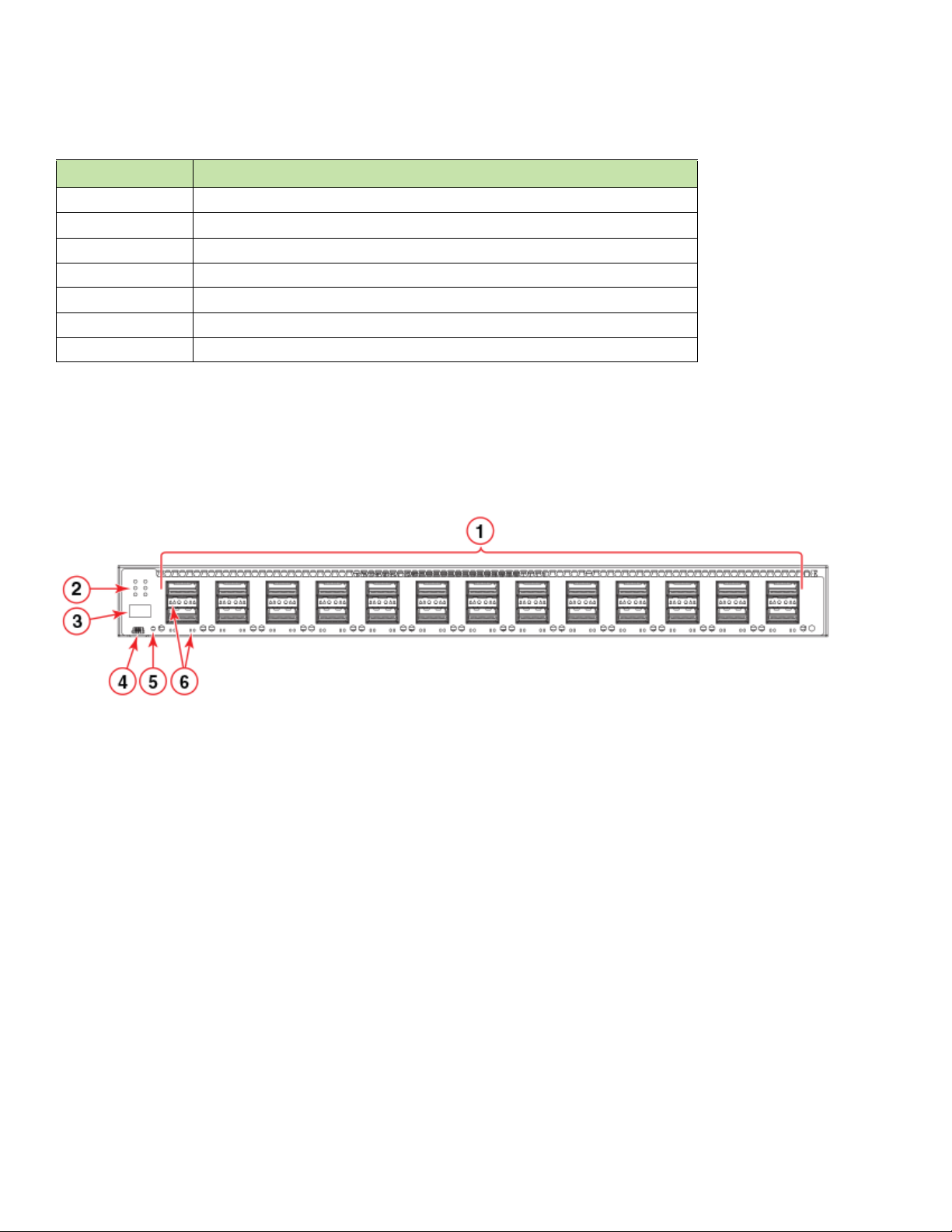
Figure 1 shows the front view of the Brocade ICX 7750-26Q switch.
FIGURE 1 Front view of the Brocade ICX 7750-26Q
1 QSFP+ ports XL1/1 - XL1/20 and XL2/1 - XL2/6 2 Console port
3 System LEDs 4 Reset button
5 Stack unit ID display 6 QSFP+ port LEDs
Figure 2 shows the front view of the Brocade ICX 7750-48F switch.
4 Brocade ICX 7750 Switch Hardware Installation Guide
53-1003900-02
Page 15
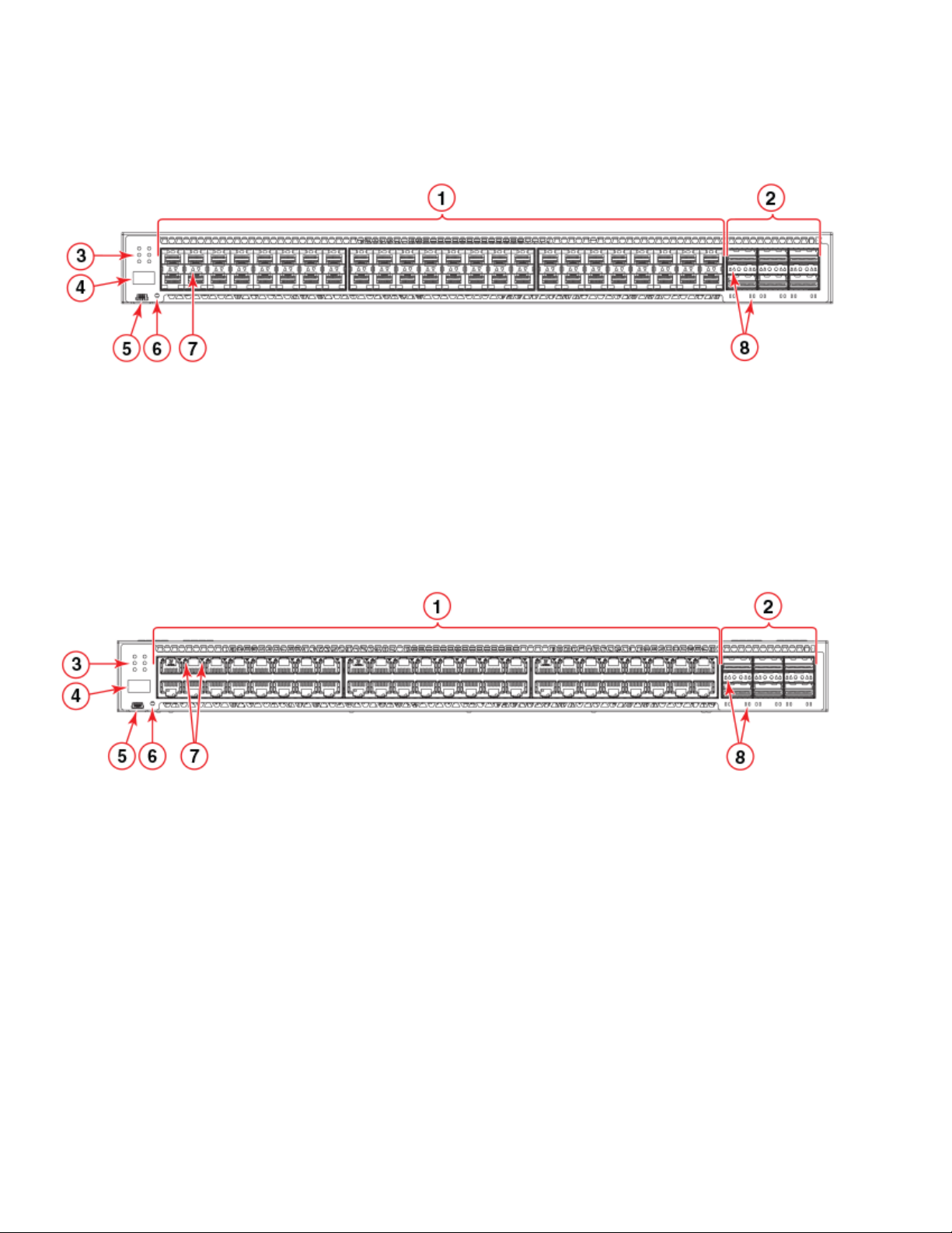
FIGURE 2 Front view of the Brocade ICX 7750-48F
1 SFP+ ports 1/1 - 1/48 2 Console port
3 QSFP+ ports XL2/1 - XL2/6 4 Reset button
5System LEDs 6SFP+ port LEDs
7 Stack unit ID display 8 QSFP+ port LEDs
Figure 3 shows the front view of the Brocade ICX 7750-48C switch.
Views of the Brocade ICX 7750 switch
FIGURE 3 Front view of the Brocade ICX 7750-48C
1 10GBase-T RJ-45 ports 1/1 - 1/48 2 Console port
3 QSFP+ ports XL2/1 - XL2/6 4 Reset button
5 System LEDs 6 10GBase-T port LEDs
7 Stack unit ID display 8 QSFP+ port LEDs
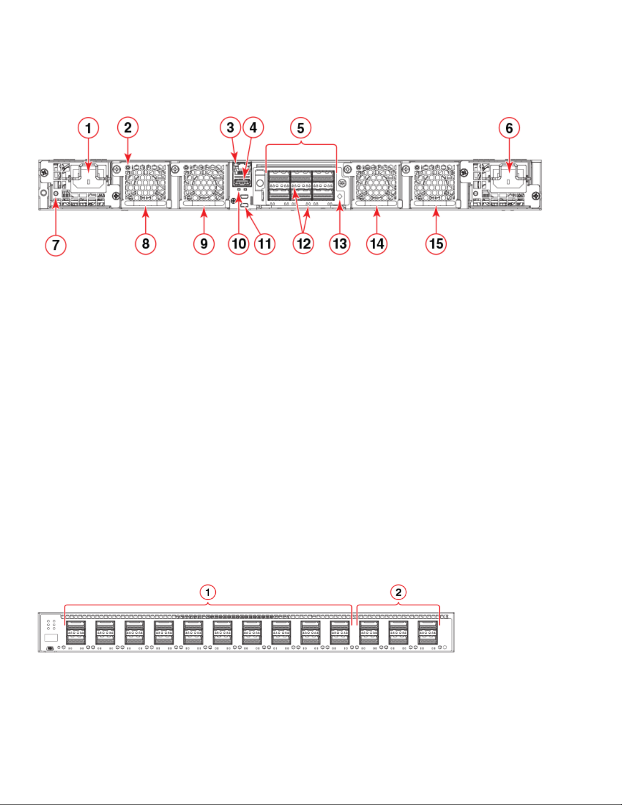
Figure 4 shows the rear view of the Brocade ICX 7750 switch.
Brocade ICX 7750 Switch Hardware Installation Guide 5
53-1003900-02
Page 16
Brocade ICX 7750 slot and Ethernet port numbering
FIGURE 4 Rear view of the Brocade ICX 7750
1 Power supply unit 2 2 Fan tray 3
3 Fan tray LED 4 UP and DN port LEDs
5 Management port 6 Control path UP and DN ports (currently not used)
7 USB port 8 QSFP+ module LEDs
9 6-port 10/40 GbE QSFP+ expansion module 10 Expansion module power LED
11 Power supply unit 1 12 Fan tray 2
13 Power supply unit 2 LED 14 Fan tray 1
15 Fan tray 4
Brocade ICX 7750 slot and Ethernet port numbering
Many CLI commands require users to enter port numbers as part of the command syntax, and many show command outputs display
port numbers. The port numbers are entered and displayed in stack-unit/slot number/port number format.
The Brocade ICX 7750 contains the following slots and Ethernet ports:
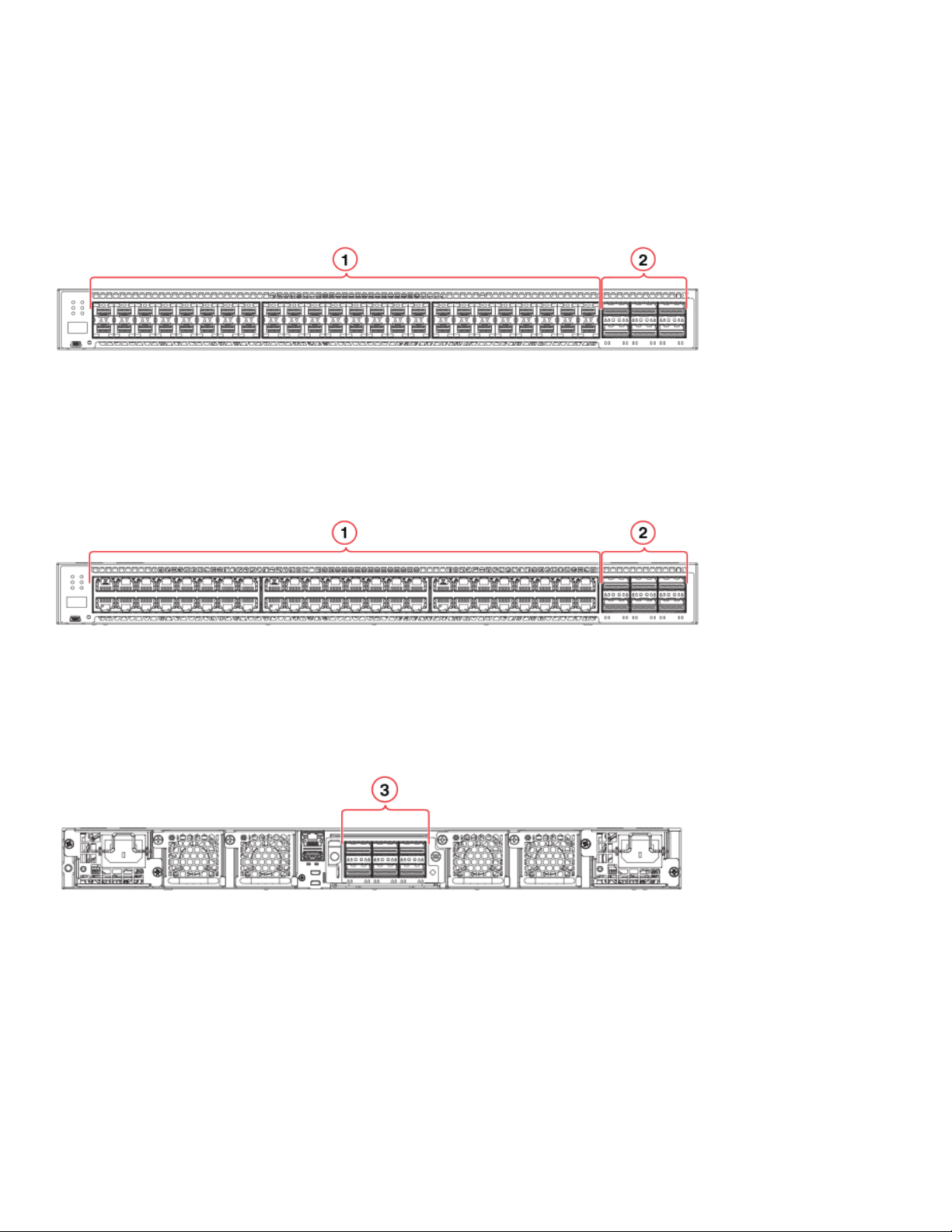
• Slot 1 and Slot 2 are located on the front of the Brocade ICX 7750-26Q device. Slot 1 contains 10/40 GbE QSFP+ ports XL1/1
through XL1/20; odd port numbers on the top row with port XL1/1 on the left and port XL1/20 on the right. Slot 2 contains 10/40
GbE QSFP+ ports XL2/1 through XL2/6; ports XL2/1, XL2/3, and XL2/5 are on the top row (left to right), and ports XL2/2,
XL2/4, and XL2/6 are on the bottom row (left to right).
FIGURE 5 Brocade ICX 7750-26Q slot numbering
1Slot 1 2Slot 2
6 Brocade ICX 7750 Switch Hardware Installation Guide
53-1003900-02
Page 17
Supported expansion module
• Slot 1 and Slot 2 are located on the front of the Brocade ICX 7750-48F device. Slot 1 contains 1/10 GbE SFP+ ports 1/1 through
1/48, with odd port numbers on the top row and port 1/1 on the left. Slot 2 contains 10/40 GbE QSFP+ ports XL2/1, XL2/3, and
XL2/5 on the top row (left to right), and ports XL2/2, XL2/4, and XL2/6 on the bottom row (left to right).
FIGURE 6 Brocade ICX 7750-48F slot numbering
1Slot 1 2Slot 2
• Slot 1 and Slot 2 are located on the front of the Brocade ICX 7750-48C device. Slot 1 contains 1/10 GbE RJ-45 ports 1/1 through
1/48, with odd port numbers on the top row and port 1/1 on the left. Slot 2 contains 10/40 GbE QSFP+ ports XL2/1, XL2/3, and
XL2/5 on the top row (left to right), and ports XL2/2, XL2/4, and XL2/6 on the bottom row (left to right).
FIGURE 7 Brocade ICX 7750-48C slot numbering
1Slot 1 2Slot 2
• Slot 3 is located on the rear of the Brocade ICX 7750 switches and contains ports XL3/1, XL3/3, and XL3/5 on the top row (left
to right) and ports XL3/2, XL3/4, and XL3/6 on the bottom row (left to right). These ports are 10/40 GbE QSFP+ ports.
FIGURE 8 Brocade ICX 7750 rear slot numbering
1Slot 3
Supported expansion module
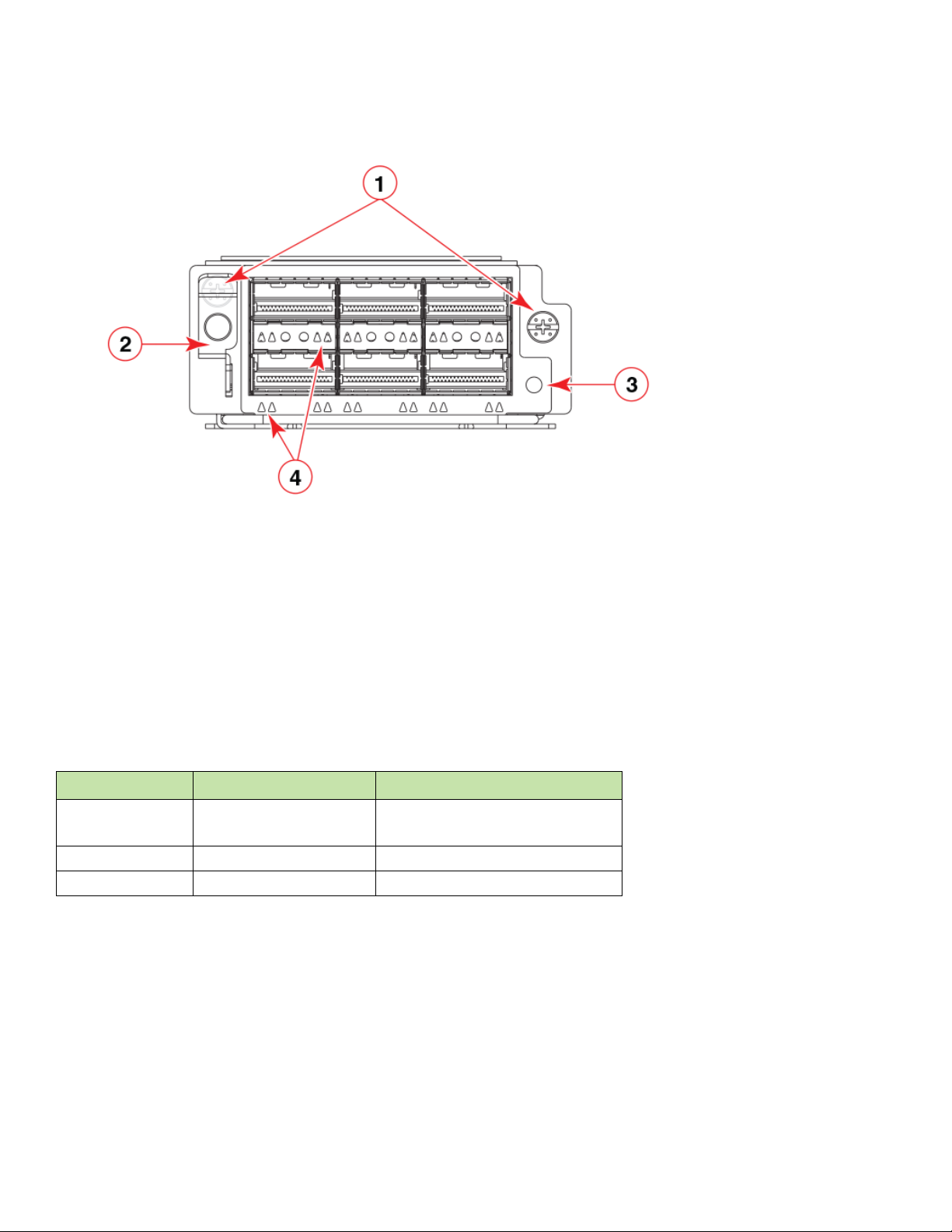
A 6-port 10/40 GbE QSFP+ expansion/stacking module can be purchased and installed in the rear of the Brocade ICX 7750. The
module supports a range of 10 GbE and 40 GbE optics (refer to the Brocade Optics Family Data Sheet).
Instructions for installing or replacing an expansion/stacking module are described in “Replacing an expansion module” on page 47.
Brocade ICX 7750 Switch Hardware Installation Guide 7
53-1003900-02
Page 18
Supported transceivers and cables
FIGURE 9 10/40 GbE QSFP+ expansion module
1 Assembly screws 2 Expansion module power LED
3 Release lever latch 4 QSFP+ slot LEDs
Supported transceivers and cables
For a list of supported transceivers and cables, refer to the Brocade Optics Family Data Sheet.
QSFP+ 40GBase-LR4 support
The Brocade ICX 7750 supports 40GBASE-LR4 QSFP+ LC optics (up to 10 km over SMF) in the port ranges shown in Table 4.
TABLE 4 Brocade ICX 7750 40GBase-LR4 support
Model Front panel ports Optional 40 GbE module ports
ICX 7750-26Q 1/1/1 through 1/1/20
1/2/1 through 1/2/6
ICX 7750-48F 1/2/5 and 1/2/6 1/3/5 and 1/3/6
ICX 7750-48C 1/2/5 and 1/2/6 1/3/5 and 1/3/6
The Brocade ICX 7750 also supports 40GBASE-SR-BD bi-directional (BiDi) QSFP+ transceivers with duplex LC optics. The 40 GbE
BiDi optics support two 20 GbE channels over duplex fiber cable, with the transmit and receive of each channel operating at two
wavelengths on a single fiber.
1/3/5 and 1/3/6
The 40 GbE BiDi transceivers enable 40 GbE links to be supported on installed 10 GbE duplex fiber infrastructure. This optic has the
same port limitations as the LR4 optic..
8 Brocade ICX 7750 Switch Hardware Installation Guide
53-1003900-02
Page 19
Supported transceivers and cables
Breakout cables
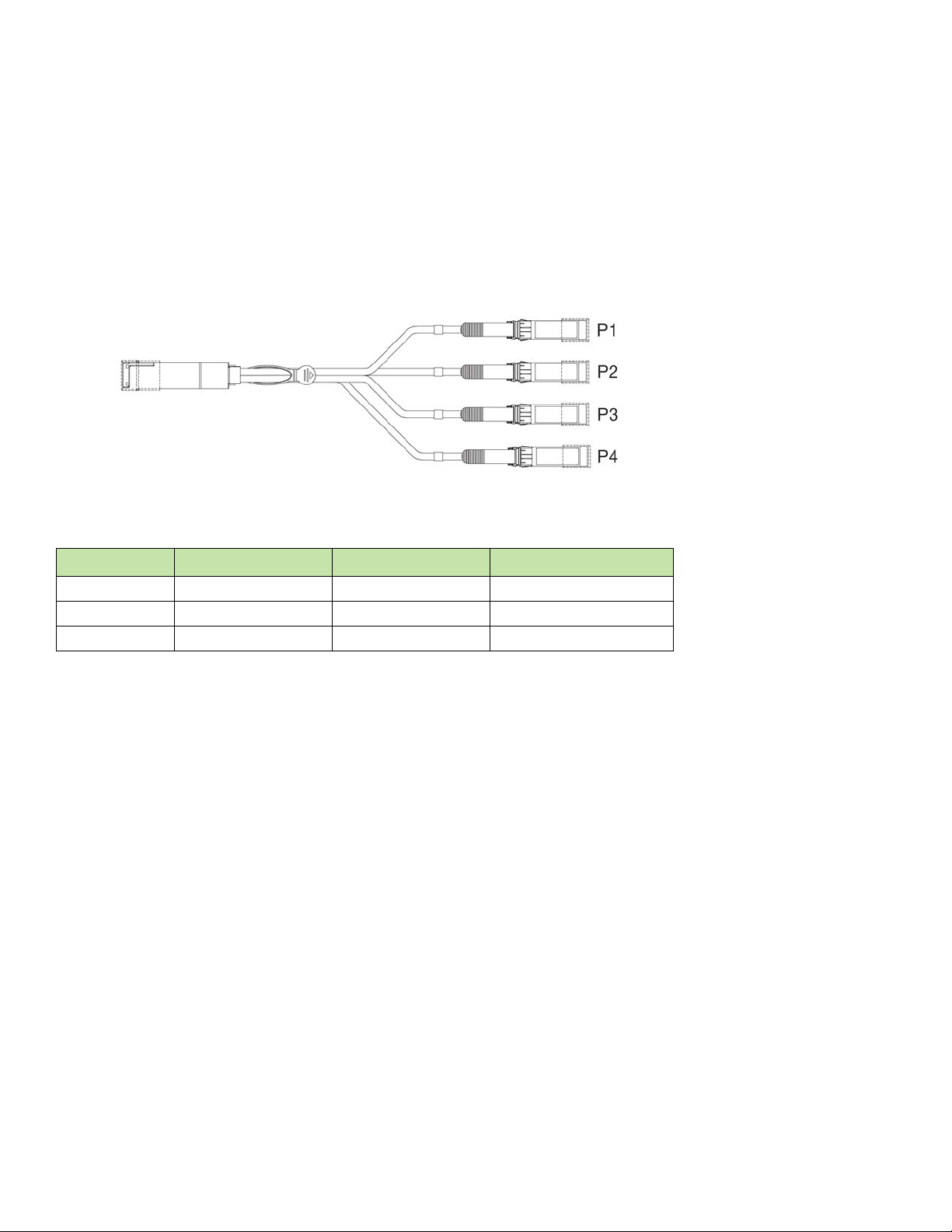
The Brocade ICX 7750 can support the following breakout cables on certain 40 GbE ports:
• QSFP+ to 4 SFP+ (4x10 GbE) direct-attach copper breakout cables, lengths of 1, 3, and 5 m
• 4x10 GbE QSFP+ SR4 compatible with 10GBase-SR SFP+ using 1, 2, 3, 5, 7, 10, 15, and 100 m lengths of fiber cable
FIGURE 10 QSFP+ to 4 SFP+ (4x10 GbE) breakout cable
The Brocade ICX 7750 ports available for breakout are shown for each model in Table 5.
TABLE 5 Brocade ICX 7750 40 GbE breakout ports
Model Front panel Slot 1 ports Front panel Slot 2 ports Rear module Slot 3 ports
ICX 7750-26Q 1/1/5 through 1/1/16 1/2/1 through 1/2/6 1/3/1 through 1/3/6
ICX 7750-48F N/A 1/2/1 through 1/2/6 1/3/1 through 1/3/6
ICX 7750-48C N/A 1/2/1 through 1/2/6 1/3/1 through 1/3/6
QSFP+ to SFP+ adapter support
The Brocade ICX 7750 supports a third-party QSFP+ to SFP+ adapter for cost-effective connections between 40 GbE QSFP+ ports and
10 GbE hardware using standard SFP+ optical cabling rather than breakout cables.
An SFP+ transceiver (SR, LR, or USR) inserted in the QSFP+ to SFP+ adapter behaves as if it is connected to the first of the 4 breakout
ports on the 40 GbE QSFP+ interface with no other ports available in the breakout. The 4x10 GbE breakout mode must be configured on
the QSFP+ interface.
Brocade ICX 7750 Switch Hardware Installation Guide 9
53-1003900-02
Page 20

Supported transceivers and cables
10 Brocade ICX 7750 Switch Hardware Installation Guide
53-1003900-02
Page 21

Installing the Brocade ICX 7750
CAUTION
• Unpacking the device . . . . . . . . . . . . . . . . . . . . . . . . . . . . . . . . . . . . . . . . . . . . . . . . . . . . . . . . . . . . . . . . . . . . . . . . . . . . . . . . . . . . . 11
• Installation and safety considerations. . . . . . . . . . . . . . . . . . . . . . . . . . . . . . . . . . . . . . . . . . . . . . . . . . . . . . . . . . . . . . . . . . . . . . . 11
• Installation tasks . . . . . . . . . . . . . . . . . . . . . . . . . . . . . . . . . . . . . . . . . . . . . . . . . . . . . . . . . . . . . . . . . . . . . . . . . . . . . . . . . . . . . . . . . 13
• Installation precautions . . . . . . . . . . . . . . . . . . . . . . . . . . . . . . . . . . . . . . . . . . . . . . . . . . . . . . . . . . . . . . . . . . . . . . . . . . . . . . . . . . . 14
• Installing the device in a rack or cabinet. . . . . . . . . . . . . . . . . . . . . . . . . . . . . . . . . . . . . . . . . . . . . . . . . . . . . . . . . . . . . . . . . . . . 15
• Grounding the system. . . . . . . . . . . . . . . . . . . . . . . . . . . . . . . . . . . . . . . . . . . . . . . . . . . . . . . . . . . . . . . . . . . . . . . . . . . . . . . . . . . . 19
• Powering on the system. . . . . . . . . . . . . . . . . . . . . . . . . . . . . . . . . . . . . . . . . . . . . . . . . . . . . . . . . . . . . . . . . . . . . . . . . . . . . . . . . . 19
• Power supplies . . . . . . . . . . . . . . . . . . . . . . . . . . . . . . . . . . . . . . . . . . . . . . . . . . . . . . . . . . . . . . . . . . . . . . . . . . . . . . . . . . . . . . . . . 20
• Attaching a PC or terminal. . . . . . . . . . . . . . . . . . . . . . . . . . . . . . . . . . . . . . . . . . . . . . . . . . . . . . . . . . . . . . . . . . . . . . . . . . . . . . . 23
• Connecting to the management port . . . . . . . . . . . . . . . . . . . . . . . . . . . . . . . . . . . . . . . . . . . . . . . . . . . . . . . . . . . . . . . . . . . . . 24
• Installing an SFP+ or a QSFP+ transceiver. . . . . . . . . . . . . . . . . . . . . . . . . . . . . . . . . . . . . . . . . . . . . . . . . . . . . . . . . . . . . . . . 24
• Connecting network devices . . . . . . . . . . . . . . . . . . . . . . . . . . . . . . . . . . . . . . . . . . . . . . . . . . . . . . . . . . . . . . . . . . . . . . . . . . . . . 25
• Stacking Brocade ICX 7750 switches . . . . . . . . . . . . . . . . . . . . . . . . . . . . . . . . . . . . . . . . . . . . . . . . . . . . . . . . . . . . . . . . . . . . 27
Procedures in this manual are intended for qualified service personnel.
Unpacking the device
The Brocade ICX 7750 ships with all of the items listed in the following list. Verify the contents of your shipping container. If any items are
missing, contact the place of purchase.
The following items are included in your shipping carton:
• A Brocade ICX 7750 switch
• One accessory kit, containing two mounting ears and eight screws
• One console cable (Mini-USB to RJ-45) with RJ-45-to-DB-9 adapter
• Two Micro-HDMI to RJ-45 stack control-path cables, currently not used by the switch
• One control-path cable holder kit, containing one cable holder and one screw
• One grounding kit, containing one grounding lug and one grounding screw
• Installed filler panels for the PSU 2 slot, expansion module slot, and fan tray slot 1
Installation and safety considerations
You can install the Brocade ICX 7750 in the following ways:
• As a standalone unit on a flat surface.
• In an EIA cabinet using a fixed-rail rack mount kit. The optional 4-post universal rack mount kit can be ordered from your switch
retailer to support up to a 30-inch deep rack. The 4-post rack mount kit includes mid-mount and rear-mount brackets.
• In a 2-post Telco rack using a flush mount rack kit. The 2-post rack mount ears are included with the switch.
Brocade ICX 7750 Switch Hardware Installation Guide 11
53-1003900-02
Page 22

Installation and safety considerations
Electrical considerations
To install and operate the switch successfully, ensure compliance with the following requirements:
• The primary outlet is correctly wired, protected by a circuit breaker, and grounded in accordance with local electrical codes.
• The supply circuit, line fusing, and wire size are adequate, as specified by the electrical rating on the switch nameplate.
• The power supply standards are met.
Environmental considerations
For successful installation and operation of the switch, ensure that the following environmental requirements are met:
• Because the Brocade ICX 7750 can be ordered with fans that move air either front to back or back to front, be sure to orient your
switch with the airflow pattern of any other devices in the rack. All equipment in the rack should force air in the same direction to
avoid intake of exhaust air.
• Some combinations of intake and exhaust airflows may not be compatible with your environment. Consult your fan and power
supply module FRU kit to determine the correct configuration.
• The ambient air temperature does not exceed 50°C (122°F) while the Brocade ICX 7750-26Q or Brocade ICX 7750-48F switch
is operating, or 40°C (104°F) while the Brocade ICX 7750-48C switch is operating.
Location considerations
Before installing the device, plan its location and orientation relative to other devices and equipment. Devices can be mounted in a
standard 19-inch equipment rack or on a flat surface.
The site should meet the following requirements:
• Maintain the operating environment as specified in “Environmental considerations” on page 12.
• Allow a minimum of 3 in. of space between the front and the back of the device and walls or other obstructions for proper airflow.
• Allow at least 3 in. of space at the front and back of the device for the twisted-pair, fiber-optic, and power cabling.
• Allow access for installing, cabling, and maintaining the devices.
• Allow the status LEDs to be clearly visible.
• Allow for twisted-pair cables to be routed away from power lines, fluorescent lighting fixtures, and other sources of electrical
interference, such as radios and transmitters.
• Allow for the unit to be connected to a separate grounded power outlet that provides 100 to 240 VAC, 50 to 60 Hz, is within 2
m (6.6 ft) of each device, and is powered from an independent circuit breaker. As with any equipment, a filter or surge suppressor
is recommended.
Cabinet considerations
For successful installation and operation of the switch in a cabinet, ensure the following cabinet requirements are met:
• The cabinet must be a standard EIA cabinet.
• The equipment in the cabinet is grounded through a reliable branch circuit connection and maintains ground at all times. Do not
rely on a secondary connection to a branch circuit, such as a power strip.
• Airflow and temperature requirements are met on an ongoing basis, particularly if the switch is installed in a closed or
multicabinet assembly.
• The additional weight of the switch does not exceed the cabinet’s weight limits or unbalance the cabinet in any way.
• The cabinet is secured to ensure stability in case of unexpected movement, such as an earthquake.
12 Brocade ICX 7750 Switch Hardware Installation Guide
53-1003900-02
Page 23

Installation tasks
NOTE
CAUTION
Recommendations for cable management
Cables can be organized and managed in a variety of ways; for example, use cable channels on the sides of the cabinet or patch panels to
reduce the potential for tangling the cables. The following list provides some recommendations for cable management:
Before plugging a cable to any port, be sure to discharge any static charge stored on the cable by touching the electrical
contacts to ground surface.
You should not use tie wraps with fiber-optic cables because they are easily overtightened and can damage the optical fibers.
Velcro-like wraps are recommended.
• Plan for the rack space required for cable management before installing the switch.
• Leave at least 1 m (3.28 ft) of slack for each port cable. This provides room to remove and replace the switch, allows for
inadvertent movement of the rack, and helps prevent the cables from being bent to less than the minimum bend radius.
• For easier maintenance, label the cables and record the devices to which they are connected.
• Keep LEDs visible by routing port cables and other cables away from the LEDs.
Installation tasks
Follow the steps listed in Table 6 to install your device. Details for each of these steps are provided on the pages indicated.
TABLE 6 Installation tasks
Task
number
1 Ensure that the physical environment that will host the device has the proper
2 If customizing a Brocade ICX 7750 baseline chassis:
3 Install the device in an equipment rack. “Installing the device in a rack or cabinet” on page 15
4 Attach a terminal or PC to the device. This will enable you to configure the
5 Plug the device into a nearby power source that adheres to the regulatory
6 Assign a password for additional access security. No default password is
7 Before attaching equipment to the device, you must configure an interface IP
8 Connect network equipment to the system. “Connecting network devices” on page 25
9 Test IP connectivity to other devices by pinging them and tracing routes. Brocade FastIron Management Configuration Guide
10 Continue configuring the device using the CLI. Brocade FastIron Management Configuration Guide
11 Secure access to the device. Brocade FastIron Management Configuration Guide
Task Where to find more information
“Installation and safety considerations” on page 11
cabling and ventilation.
“Installing and replacing a power supply unit” on
1 Install at least one power supply unit.
2 Install at least three fans.
3 Install an expansion module.
device through the command line interface (CLI).
requirements outlined in this manual.
assigned to the CLI.
address to the subnet on which the device will be located. Initial IP address
configuration is performed using the CLI with a direct serial connection.
page 20
“Installing or replacing the fan tray” on page 46
“Installing or replacing an expansion module” on
page 47
“Grounding the system” on page 19
“Powering on the system” on page 19
Brocade FastIron Management Configuration Guide
Brocade FastIron Management Configuration Guide
Brocade ICX 7750 Switch Hardware Installation Guide 13
53-1003900-02
Page 24
Installation precautions
DANGER
CAUTION
CAUTION
CAUTION
DANGER
DANGER
CAUTION
DANGER
Installation precautions
Follow all precautions when installing a device.
General precautions
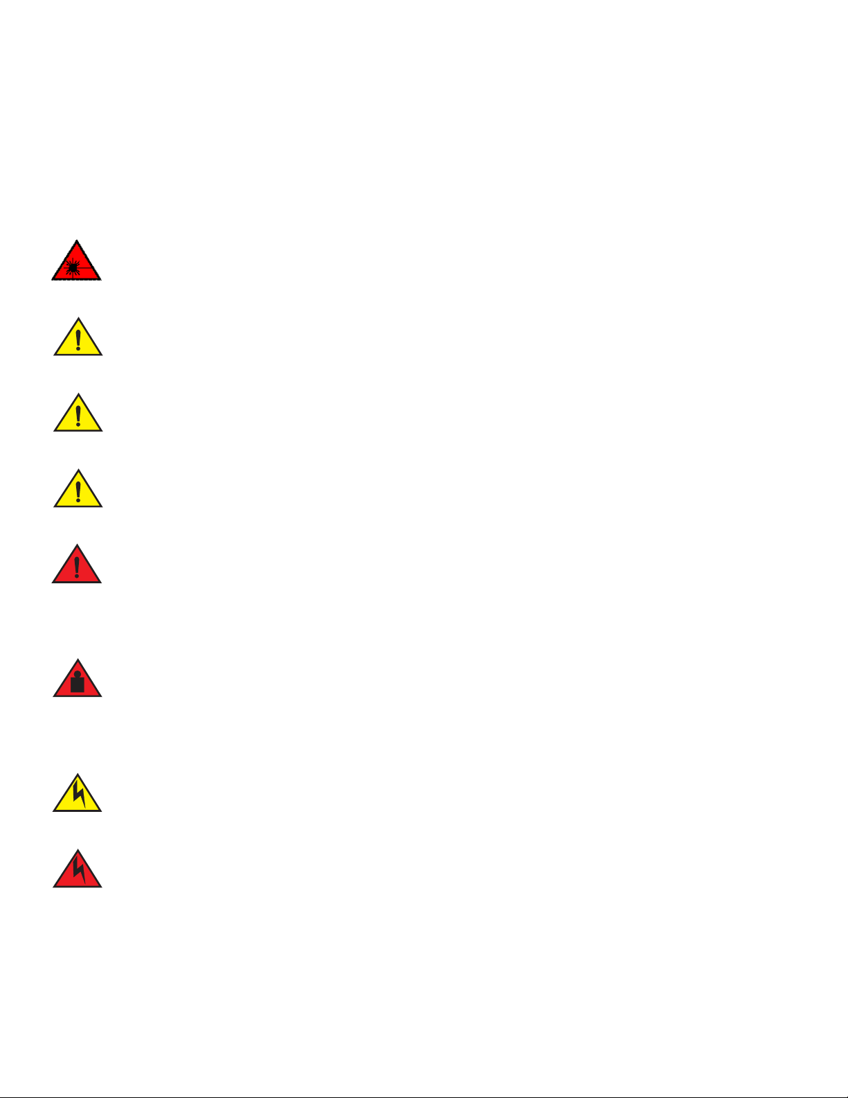
Laser radiation. Do not view directly with optical instruments. Class 1M laser products.
Do not install the device in an environment where the operating ambient temperature might exceed 50°C (122°F).
Make sure the airflow around the front and sides of the device is not restricted.
Never leave tools inside the device.
Risk of explosion if battery is replaced by an incorrect type. Dispose of used batteries according to the manufacturer’s
instructions.
Lifting precautions
Make sure the rack or cabinet housing the device is adequately secured to prevent it from becoming unstable or falling over.
Power precautions
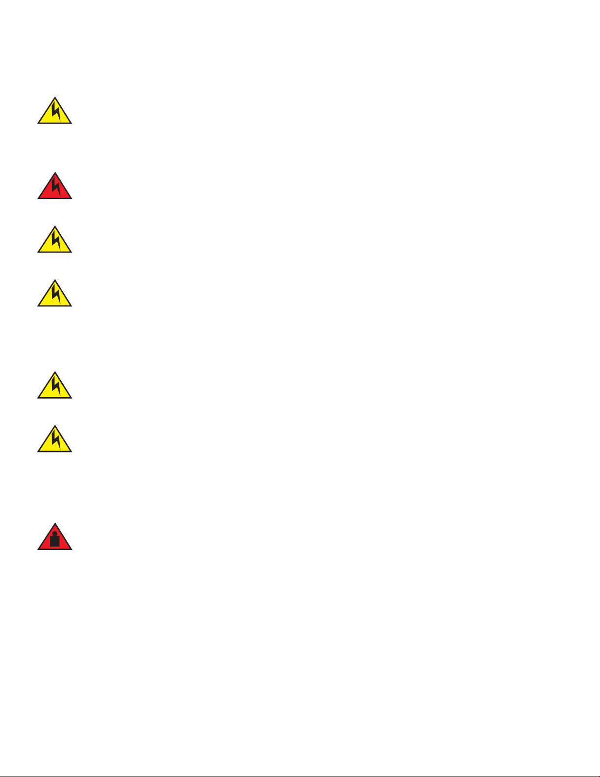
Use a separate branch circuit for each AC power cord, which provides redundancy in case one of the circuits fails.
To avoid high voltage shock, do not open the device while the power is on.
14 Brocade ICX 7750 Switch Hardware Installation Guide
53-1003900-02
Page 25
Installing the device in a rack or cabinet
NOTE
CAUTION
DANGER
CAUTION
CAUTION
CAUTION
CAUTION
DANGER
Ensure that the device does not overload the power circuits, wiring, and over-current protection. To determine the possibility
of overloading the supply circuits, add the ampere (amp) ratings of all devices installed on the same circuit as the device.
Compare this total with the rating limit fo the circuit. The maximum ampere ratings are usually printed on the devices near the
input power connectors.
Disconnect the power cord from all power sources to completely remove power from the device.
Before plugging a cable to any port, be sure to discharge any static charge stored on the cable by touching the electrical
contacts to ground surface.
If the installation requires a different power cord than the one supplied with the device, make sure you use a power cord
displaying the mark of the safety agency that defines the regulations for power cords in your country. The mark is your
assurance that the power cord can be used safely with the device.
DC-DC power source cautions
For DC systems, use grounding wire of at least 12 American Wire Gauge (AWG). The grounding wire should be attached to the
DC input connector (as shown in Figure 18); the other end connects to the building ground.
For the DC input circuit to the system, make sure there is a 20 Amp circuit breaker, minimum 60 VDC, double pole, on the
input terminal block to the power supply. The input wiring for connection to the product should be copper wire, 12 AWG,
marked VW-1, and rated minimum 90°C.
Installing the device in a rack or cabinet
Make sure the rack or cabinet housing the device is adequately secured to prevent it from becoming unstable or falling over.
You need a #2 Phillips screwdriver for installation.
Before mounting the switch in a rack, pay particular attention to the following factors:
• Temperature: Because the temperature within a rack assembly may be higher than the ambient room temperature, check that
the rack-environment temperature is within the specified operating temperature range. (Refer to “Environmental considerations”
on page 12.)
Brocade ICX 7750 Switch Hardware Installation Guide 15
53-1003900-02
• Mechanical loading: Do not place any equipment on top of a rack-mounted unit.
• Circuit overloading: Be sure that the supply circuit to the rack assembly is not overloaded.
Page 26
Installing the device in a rack or cabinet
NOTE
• Grounding: Rack-mounted equipment should be properly grounded. Particular attention should be given to supply connections
other than direct connections to the mains electricity supply.
2-post rack mount installation
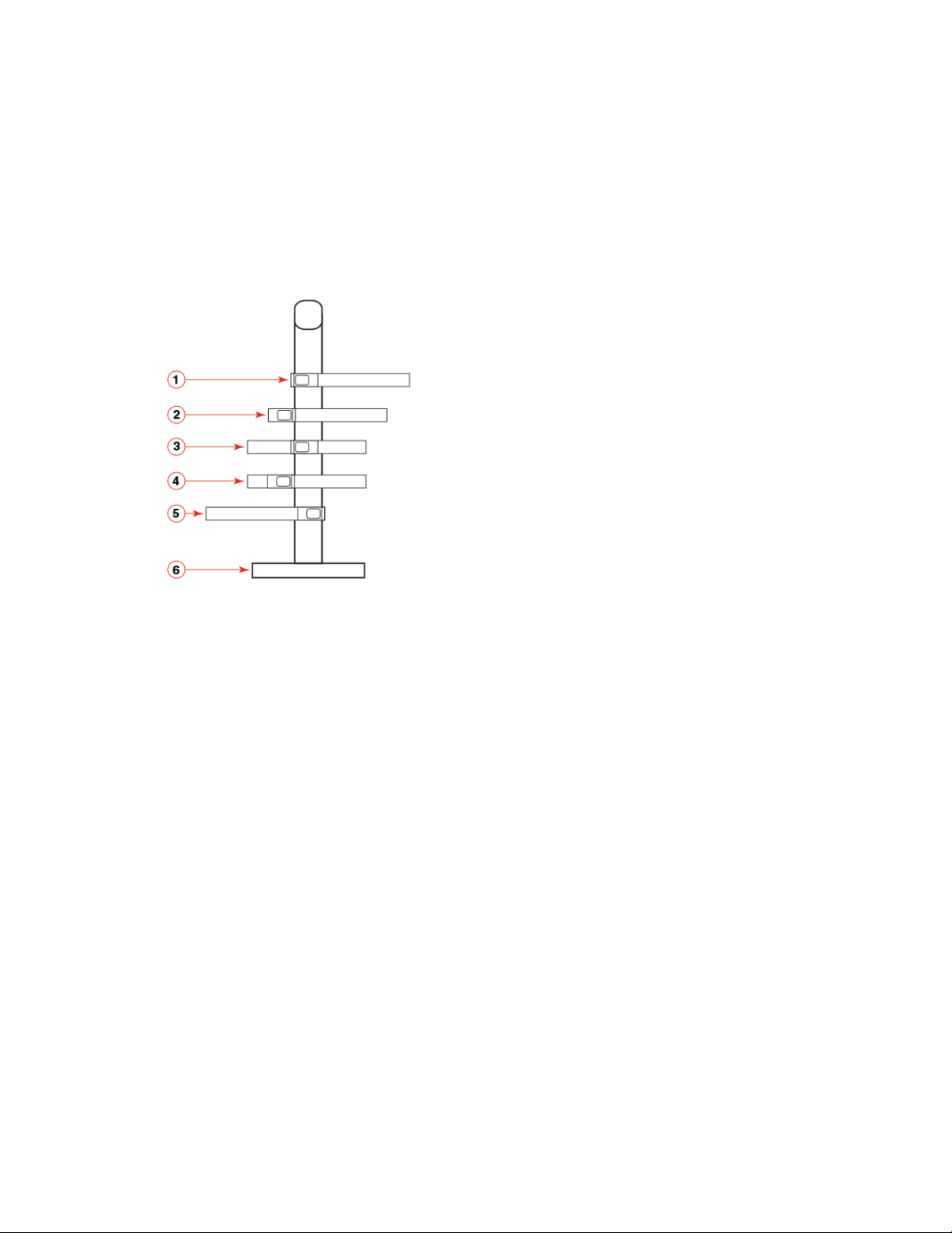
The Brocade ICX 7750 can be installed in a 2-post rack in various mounting positions, as shown in Figure 11.
FIGURE 11 2-post rack mounting positions
1 Front flush mount 2 Reverse mid-mount
3 Reverse-front mount 4 Rear mount
5 Front mid-mount 6 2-post rack, side view
Use the following procedure when installing the Brocade ICX 7750 in a 2-post Telco rack only. If an ICX 7750 device is to be
installed into a standard 4-post rack, make sure that the correct rack mount kit has been purchased. For 4-post racks, follow the
procedures in “4-post rack mount installation” on page 17.
Use the following steps to mount the Brocade ICX 7750 in a 2-post rack.
1. Remove the rack mount kit from the shipping carton. The kit contains the following items:
• Two L-shaped mounting brackets
• Eight 8-32 x 5/16 in., panhead Phillips screws
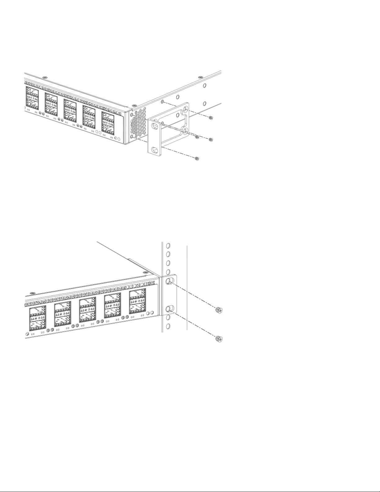
2. Attach the mounting brackets to the sides of the device as illustrated in Figure 12 using the
8-32 x 5/16 in. screws.
16 Brocade ICX 7750 Switch Hardware Installation Guide
53-1003900-02
Page 27
Installing the device in a rack or cabinet
NOTE
FIGURE 12 Attaching the mounting brackets for a Brocade ICX 7750
3. Position the device in the cabinet, providing temporary support under the switch until the rail kit is secured to the cabinet.
4. Attach the front right bracket to the rail rack using two 10-32 x 5/8 in. screws and the appropriate round-hole or square-hole
retainer nuts.
5. Repeat step 4 to attach the left front bracket to the left front rack rail and tighten all 10-32 x 5/8 in. screws to a torque of 25 in-lb
(29 cm-kg). Refer to Figure 13.
FIGURE 13 Installing the Brocade ICX 7750 in a 2-post rack
Proceed to “Grounding the system” on page 19.
4-post rack mount installation
Kits for 4-post rack mounting are not included in the shipping carton and must be ordered separately.
Use the following procedure when installing the Brocade ICX 7750 in a 4-post rack cabinet. For 2-post cabinets, follow the
procedures in “2-post rack mount installation” on page 16.
Brocade ICX 7750 Switch Hardware Installation Guide 17
53-1003900-02
Page 28

Installing the device in a rack or cabinet
NOTE
Use the following steps to mount the Brocade ICX 7750 in a 4-post rack.
1. Remove the rack mount kit from the shipping carton. The kit contains the following items:
• Two L-shaped mid-mount brackets.
• Four rack mount rails: two for side attach and two for rear attach racks.
• Thirty-two 8-32 x 5/16 in., panhead Phillips screws with patchlocks.
• Eight 10-32 x 5/8 in., panhead Phillips screws. Refer to item 1 in Figure 14.
• Eight 32-10 retainer nuts (for square-hole rack rails). Refer to item 2 in Figure 14.
• Eight 32-10 retainer nuts (for round-hole rack rails). Refer to item 3 in Figure 14.
FIGURE 14 4-post screws and retainer nuts
1 10-32 x 5/8 in. panhead Phillips screw 2 32-10 retainer nut (for round-hole rack rails)
3 32-10 retainer nut (for square-hole rack rails)
Use the hardware supplied in the 4-post mounting kit for mid-mounting the Brocade ICX 7750 in a 4-post rack. When front-flush
or reverse mounting in a 4-post rack, use the L-shaped brackets from the 2-post rack mounting kit instead of those in the 4-post
kit to prevent the side cooling vents from being blocked.
2. Attach the mounting brackets to the sides of the device as illustrated in Figure 12 using the 8-32 x 5/16 in. screws. Note that
4-post rack installation also supports mid-mount options.
3. Attach the appropriate rails: either side attach or rear attach as determined by the type of rack in which you are installing the
device.
4. Position the switch in the cabinet, providing temporary support under the switch until the rail kit is secured to the cabinet.
5. Attach the front right bracket to the rail rack using two 10-32 x 5/8 in. screws and the appropriate round-hole or square-hole
retainer nuts.
6. Repeat step 5 to attach the left front bracket to the left front rack rail and tighten all 10-32 x 5/8 in. screws to a torque of 25 in-lb
(29 cm-kg). Refer to Figure 13.
7. Attach the rear right bracket to the rail rack using two 10-32 x 5/8 in. screws and the appropriate round-hole or square-hole
retainer nuts.
8. Repeat step 7 to attach the rear left bracket to the rack rail and tighten all 10-32 x 5/8 in. screws to a torque of 25 in-lb (29
cm-kg).
Proceed to “Grounding the system” on page 19.
18 Brocade ICX 7750 Switch Hardware Installation Guide
53-1003900-02
Page 29
Grounding the system
NOTE
NOTE
NOTE
Grounding the system
The rear panel of the Brocade ICX 7750 includes a single-screw grounding terminal. The surface area around this terminal is not painted
to provide a good electrical connection. Before connecting power to the device, the grounding terminal must be connected to ground to
ensure proper operation and to meet electromagnetic interference (EMI) and safety requirements.
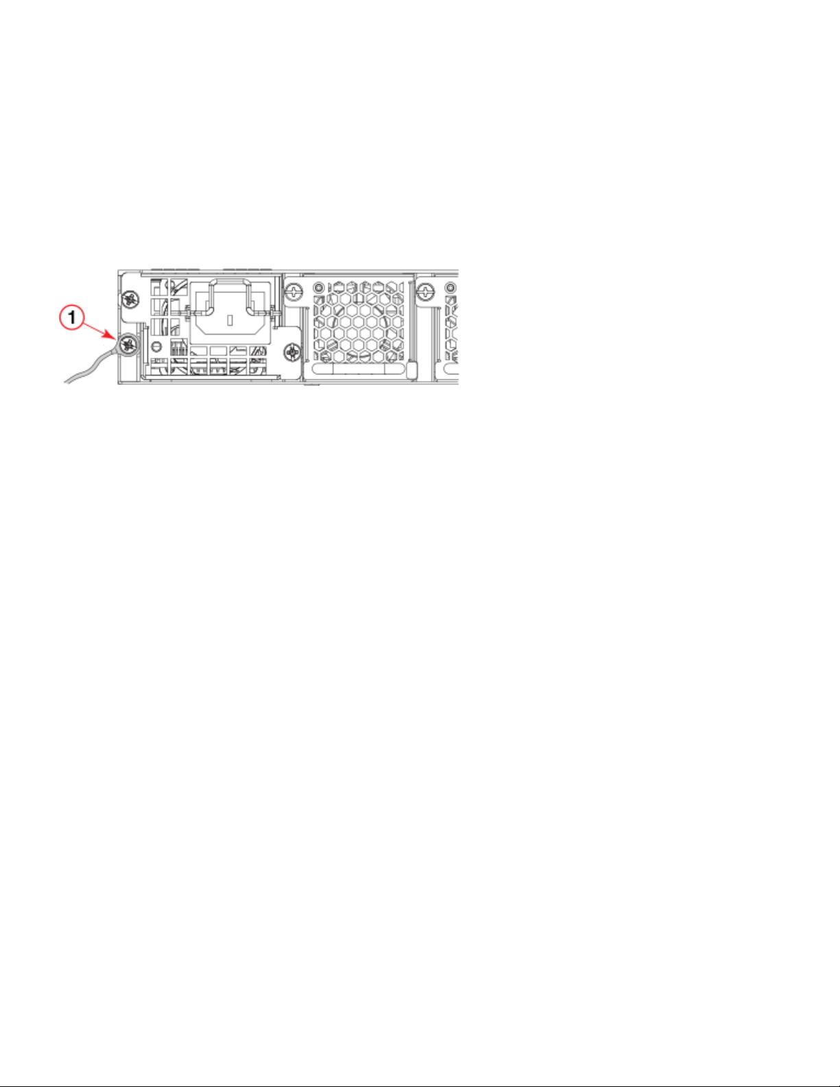
FIGURE 15 Connecting the grounding terminal
1 Grounding terminal
Use the grounding lug and screw included in the Brocade ICX 7750 grounding kit.
Perform the following steps to connect to the grounding terminal.
1. Ensure that the rack in which the Brocade ICX 7750 is mounted is properly grounded and in compliance with local regulations.
2. Ensure that there is a good electrical connection to the grounding point on the rack (no paint or isolating surface treatment).
3. Crimp the included grounding lug to a grounding wire of at least 6 American Wire Gauge (AWG). The 6 AWG wire and grounding
lug should be crimped together using a proper tool.
4. Attach the 6 AWG stranded copper wire to the grounding terminal on the Brocade ICX 7750 using the screw included in the
grouding kit.
5. Attach the grounding wire to the grounding point on the rack.
Powering on the system
After you complete the physical installation, you can power on the system.
1. Install alternating-current (AC) and direct-current (DC) power supplies in the switch.
2. Attach AC or DC power cables to the power supply connectors on the rear panel.
3. Connect the power cables to the 100-240 VAC or -48 VDC power source.
To turn the system off, simply unplug the power cable or cables.
A power source should be installed near the equipment and should be easily accessible.
Brocade ICX 7750 Switch Hardware Installation Guide 19
53-1003900-02
Page 30

Power supplies
NOTE
NOTE
CAUTION
CAUTION
Power supplies
The Brocade ICX 7750 supports alternating-current (AC) and direct-current (DC) power supplies. The Brocade ICX 7750 is capable of
running on one power supply and three fans. The second power supply and fourth fan provide redundancy.
If the second power supply and fourth fan slots are unused, you must cover them with filler panels.
Brocade recommends that the Brocade ICX 7750-48C operate with two power supplies and four fan trays installed. If a power
supply or fan tray fails, it must be replaced as soon as possible.
AC and DC power supplies cannot be installed and used in the same device. Mismatched power supplies in the same device cause
continual reboot on power up.
Installing and replacing a power supply unit
When installing or replacing a power supply unit, keep in mind the following:
• Power supplies can be swapped in or out while the device is running. The remaining power supply provides enough power for
the device.
• The airflow direction of the power supply must match that of the installed fan trays. All must be either exhaust or intake.
Power supplies are hot-swappable. However, they should be inserted or removed without a power cord being
connected to a power source to avoid damage.
For Brocade ICX 7750 devices, be sure that the airflow direction of the power supply unit matches that of installed fan
trays. The power supplies and fan trays are clearly labeled with either a green arrow with an “E”, or an orange arrow
with an “I.”
Installing an AC power supply
Use the following steps to install an AC power supply in the Brocade ICX 7750.
20 Brocade ICX 7750 Switch Hardware Installation Guide
53-1003900-02
Page 31
Power supplies
CAUTION
CAUTION
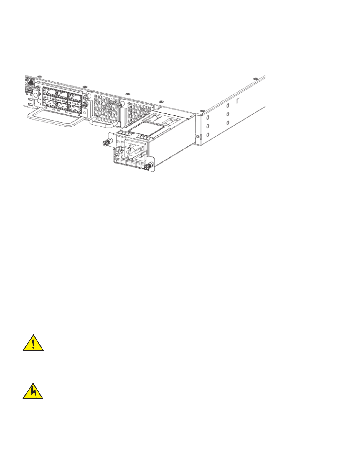
FIGURE 16 Installing an AC power supply unit
1. If replacing a power supply, remove the previously installed power supply from the appropriate slot by removing the two screws
with a Phillips screwdriver.
2. If installing a new power supply into a slot covered with a filler panel:
a. Using a Phillips screwdriver, unscrew the screws on the filler panel.
b. Remove the filler panel.
3. Before opening the package that contains the power supply, touch the bag to the switch casing to discharge any potential static
electricity. Brocade recommends using an ESD wrist strap during installation.
4. Remove the power supply from the anti-static shielded bag.
5. Holding the power supply level, guide it into the carrier rails on each side and gently push it all the way into the slot, ensuring that
it firmly engages with the connector.
6. When you are sure the power supply has properly engaged the connector, tighten the retainer screws to secure the power supply
in the slot.
When the Brocade ICX 7750 is powered on, the LEDs on the power supply rear panel should light up green to confirm that the power
supply is correctly installed and supplying power.
If you do not install a power supply in a slot, you must keep the slot panel in place. If you run the device with an uncovered slot,
the system will overheat.
Installing a DC power supply
Brocade ICX 7750 Switch Hardware Installation Guide 21
53-1003900-02
All devices with DC power supplies (Brocade ICX 7750) are intended for installation in restricted access areas only. A
restricted access area is where access can be gained only by service personnel through the use of a special tool, lock and key,
or other means of security, and is controlled by the authority responsible for the location.
Page 32
Power supplies
NOTE
AC and DC power supplies cannot be installed and used in the same device. Mismatched power supplies in the same device cause
continual reboot on power up.
Use the following steps to install a DC power supply in the Brocade ICX 7750.
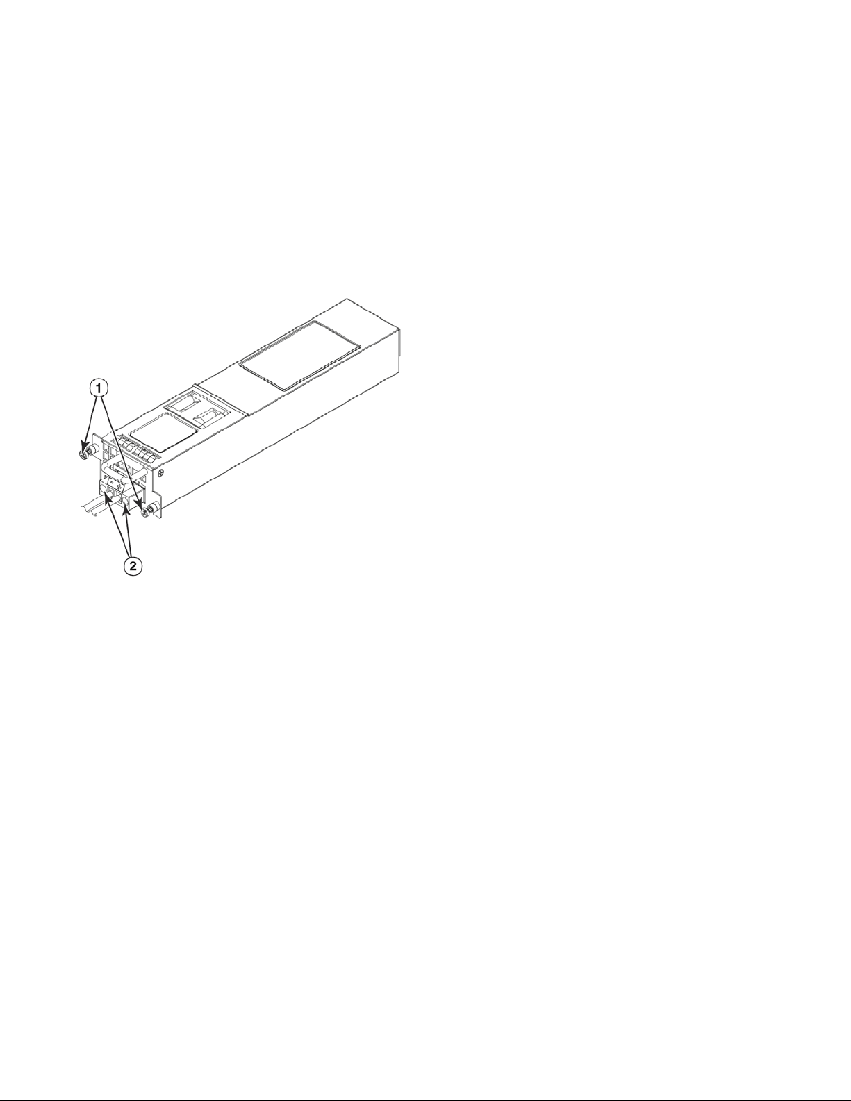
1. Remove the previously installed power supply from the appropriate slot by removing the chassis attachment screws located in
the upper right and lower left of the power supply unit using a Phillips screwdriver. Refer to item 1 in Figure 17.
FIGURE 17 DC power supply screws
1 Chassis attachment screws 2 Assembly screws
2. Before opening the package that contains the DC power supply, touch the bag of the switch casing to discharge any potential
static electricity. Brocade recommends using an ESD wrist strap during installation.
3. Remove the DC power supply from the anti-static shielded bag.
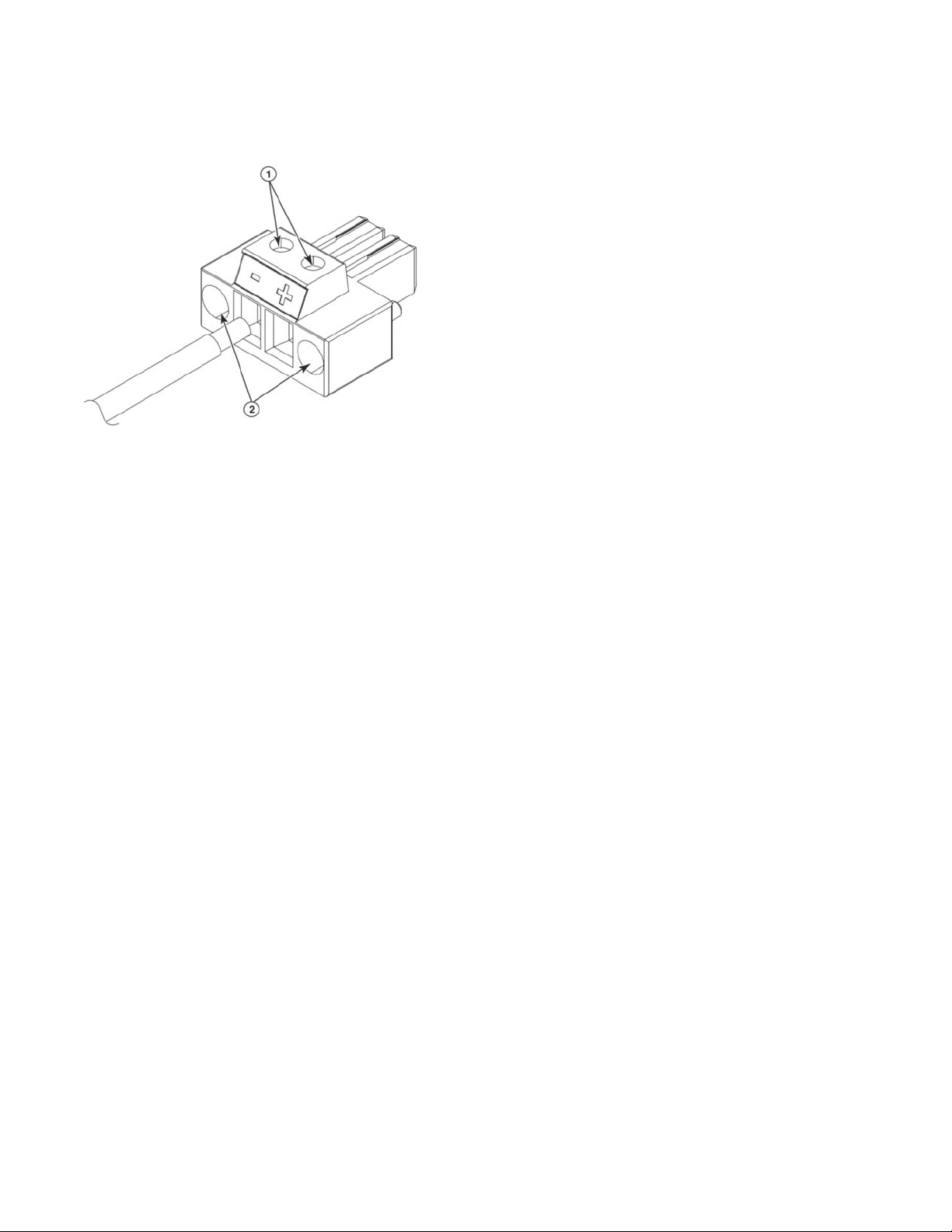
4. Insert the DC power supply source wires into the DC wiring assembly, matching the terminals. Refer to Figure 18.
22 Brocade ICX 7750 Switch Hardware Installation Guide
53-1003900-02
Page 33
Attaching a PC or terminal
NOTE
FIGURE 18 DC power supply wiring assembly
1 Wire-tightening screws 2 Assembly screws
5. Use the wire-tightening screws to secure the wires.
6. Insert the DC power supply wiring assembly with the wires connected into the power supply and tighten the assembly screws.
Refer to Figure 18.
7. Using the handle on the power supply, hold the power supply level and guide it into the carrier rails on each side of the power
supply slot. Gently push the power supply all the way into the slot, ensuring that it firmly engages with the connector.
8. When you are sure the power supply has properly engaged the connector, tighten the chassis attachment screws to secure the
power supply in the slot.
When the Brocade ICX 7750 is powered on, the power LED on the front of the device should turn green to confirm that the power supply
is correctly installed and supplying power. Refer to “Brocade ICX 7750 front-panel LEDs” on page 33.
Attaching a PC or terminal
To assign an IP address, you must have access to the command line interface (CLI). The CLI is a text-based interface that can be
accessed through a direct serial connection to the device and through Telnet connections. The CLI is described in detail in the Brocade
FastIron Management Configuration Guide.
Access the CLI by connecting to the console port. After you assign an IP address, you can access the system through Telnet, or Brocade
Network Advisor.
Use the following steps to attach a management station to the console port.
1. Connect a PC or terminal to the console management port on the front of the Brocade ICX 7750 using the mini-USB serial
console port cable and, if required, the RJ-45-to-DB-9 adapter.
For port pinout information for the mini-USB serial console port, refer to “Serial port specifications (pinout mini-USB)” on
page 52.
You must run a terminal emulation program on the PC.
2. Launch the terminal emulation program and set the following session parameters:
Brocade ICX 7750 Switch Hardware Installation Guide 23
53-1003900-02
Page 34

Connecting to the management port
NOTE
NOTE
CAUTION
DANGER
• Baud: 9600 bps
• Data bits: 8
• Parity: None
• Stop bits: 1
• Flow control: None
The console serial communication port serves as a connection point for management by a PC.
Connecting to the management port
The Gigabit Ethernet management port (RJ-45) on the Brocade ICX 7750 rear panel provides an out-of-band network connection to the
device. After you assign an IP address, you can access the Brocade ICX 7750 from anywhere in the attached network using Telnet, a web
browser, or other network management tools, such as Brocade Network Advisor. To prevent unauthorized access, Brocade recommends
that the management port only be connected to a secure private network.
To manage the Brocade ICX 7750 through its management port, connect the port to the management Ethernet network using Category
5 or better cable.
Management of the Brocade ICX 7750 is described in detail in the Brocade FastIron Management Configuration Guide.
Installing an SFP+ or a QSFP+ transceiver
To monitor the transceivers, the show media command output shows the transceiver information for all interfaces on the switch. Brocade
provides support for third-party transceivers, but may require a Brocade transceiver be used for troubleshooting.
Support will not be provided if there is an issue with a third-party transceiver.
Passive SFP+ and QSFP+ removable media devices are not supported. Use of passive devices may lead to unstable networks if
utilized. Brocade-branded removable media devices are recommended for proper operation of the switch.
You can install a new transceiver in a slot while the device is powered on and running.
Before installing or removing a fiber-optic transceiver, have the following items available:
• The protective covering that you removed from the fiber-optic transceiver port when you initially installed the module.
• An ESD wrist strap with a plug for connection to the ESD connector on the router chassis.
For safety reasons, the ESD wrist strap should contain a series 1 megohm resistor.
Laser radiation. Do not view directly with optical instruments. Class 1M laser products.
24 Brocade ICX 7750 Switch Hardware Installation Guide
When 10 GbE fiber-optic ports on the Brocade ICX 7750 are disabled, the laser light remains on even though the port link is down.
53-1003900-02
Page 35
Connecting network devices
NOTE
Use the following steps to install a transceiver:
1. Put on the ESD wrist strap and ground yourself by attaching the clip end to a metal surface (such as an equipment rack) to act as
ground.
2. Remove the new transceiver from the protective packaging.
3. Remove any protector plugs from the transceivers and the ports.
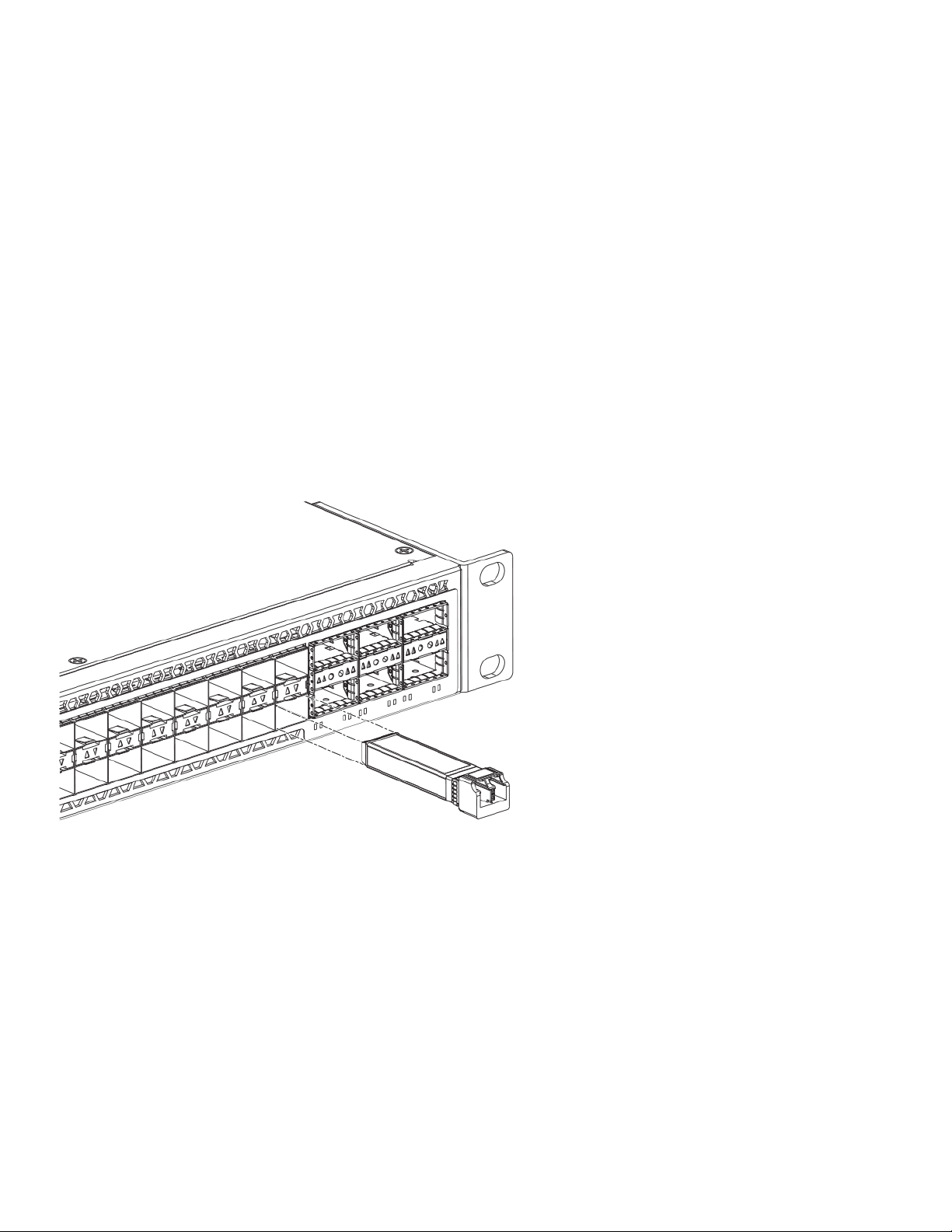
4. Making sure that the bail (wire handle) is in the unlocked position, place the transceiver in the correctly oriented position on the
port, as shown in Figure 19.
5. Slide the transceiver into the port until you feel it click into place; then close the bail. Transceivers are keyed to prevent incorrect
insertion.
Each SFP+ transceiver has a 10-pad gold-plated edge connector on the bottom. The correct position to insert an SFP+ transceiver
in the upper row of ports is with the gold-plated edge down. The correct position to insert an SFP+ transceiver in the lower row of
ports is with the gold-plated edge up.
FIGURE 19 Installing an SFP+ transceiver in a port slot
Connecting network devices
Brocade devices support connections to other vendors’ routers, switches, and hubs, as well other Brocade devices.
Connectors
For port information, refer to “Data port specifications (Ethernet)” on page 52.
Connecting a network device to a copper port
For copper connections to another Brocade device or any other devices, use straight-through or crossover UTP cabling.
Brocade ICX 7750 Switch Hardware Installation Guide 25
53-1003900-02
Page 36

Connecting network devices
NOTE
Automatic MDI or MDIX detection
All 10/100/1000 Mbps and 10 Gbps Ethernet copper ports on the devices support automatic Media Dependent Interface (MDI) and
Media Dependent Interface Crossover (MDIX) detection. Automatic MDI or MDIX detection is enabled on all copper ports by default. For
each port, you can disable automatic MDI or MDIX detection, designate the port as an MDI port, or designate the port as an MDIX port.
For more information about automatic MDI or MDIX detection and configuration details, refer to the Brocade FastIron Management
Configuration Guide.
Connecting a network device to a fiber port
For direct attachment from the device to a 1 GbE network interface card, switch, or router using a fiber-optic transceiver, you will need fiber
cabling with an LC connector.
For information about transceivers supported on Brocade ICX 7750 devices, refer to the Brocade Optics Family Data Sheet:
To connect the device to another network device using a fiber port, you must complete the following tasks:
• Install a fiber-optic transceiver (SFP+ or QSFP+). Refer to “Installing an SFP+ or a QSFP+ transceiver” on page 24.
• Cable the fiber-optic transceiver
Cabling a fiber-optic transceiver
Use the following steps to cable a fiber-optic transceiver.
1. Remove the protective covering from the fiber-optic port connectors and store the covering for future use.
2. Before cabling a fiber-optic transceiver, Brocade strongly recommends cleaning the cable connectors and the port connectors.
For more information, refer to “Cleaning the fiber-optic connectors” on page 26.
3. Gently insert the cable connector (a tab on each connector should face upward) into the transceiver connector until the tabs lock
into place.
4. Observe the link and activity LEDs to determine if the network connections are functioning properly. For more information about
the LED indicators, refer to “LED activity interpretation” on page 33.
To verify that a Brocade ICX 7750 can reach another device through the network, use the ping command at any level of the CLI.
For more information, refer to the Brocade FastIron Management Configuration Guide.
Cleaning the fiber-optic connectors
To avoid problems with the connection between the fiber-optic transceiver (SFP+ or QSFP+) and the fiber cable connectors, Brocade
strongly recommends cleaning both connectors each time you disconnect and reconnect them. Dust can accumulate in the connectors
and cause problems such as reducing the optic launch power.
To clean the fiber cable connectors, Brocade recommends using a fiber-optic reel-type cleaner. When not using an SFP+ or QSFP+
connector, make sure to keep the protective covering in place.
Connecting breakout cables to 40 GbE ports
A 40 GbE breakout cable can only be used on standalone Brocade ICX 7750 devices to break out certain 40 GbE QSFP+ ports into four
10 GbE sub-ports. (Refer to “Breakout cables” on page 9.)
26 Brocade ICX 7750 Switch Hardware Installation Guide
53-1003900-02
Page 37
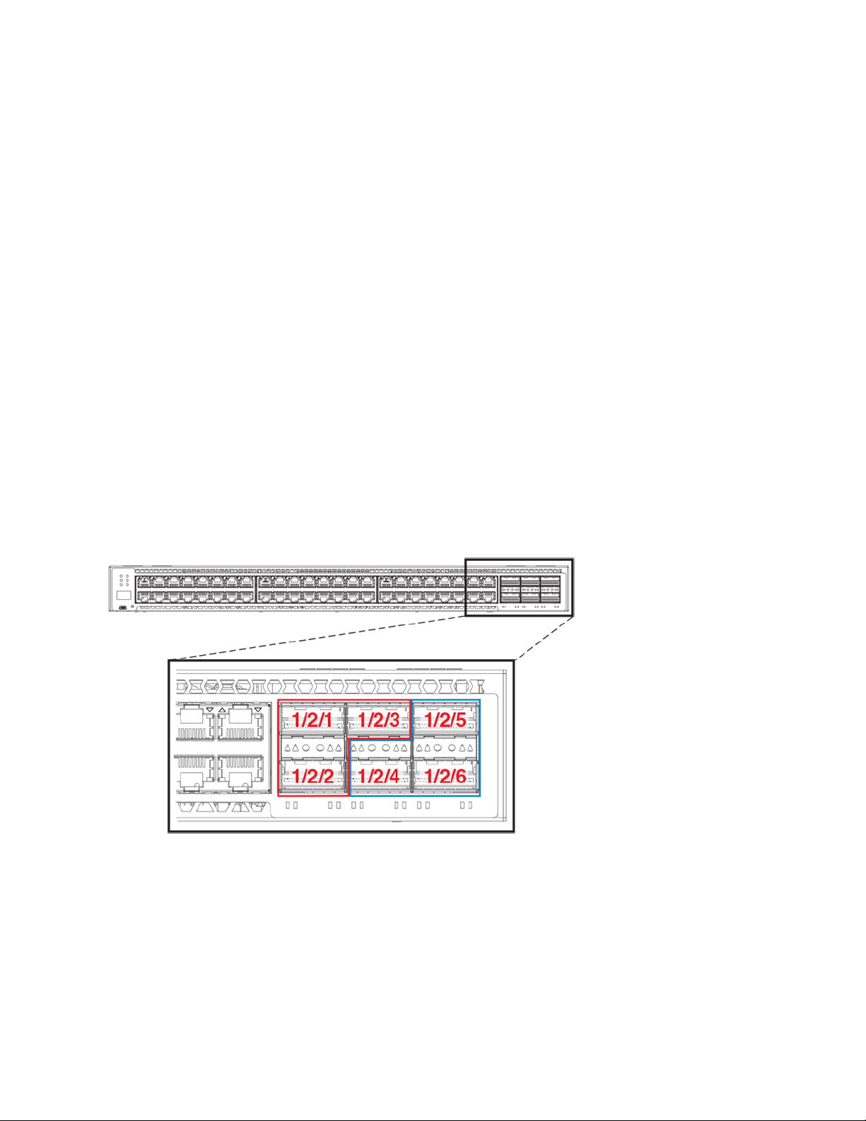
Stacking Brocade ICX 7750 switches
NOTE
NOTE
Any previous configuration must be removed from a 40 GbE port before it can be broken out into sub-ports. Refer to the Brocade
FastIron Management Configuration Guide for more information.
Stacking cannot be enabled on Brocade ICX 7750 devices that have a breakout configuration on any 40 GbE ports, and vice
versa.
Stacking Brocade ICX 7750 switches
Brocade ICX 7750 devices support chassis-class high availability stacking with hitless failover on six full-duplex 40 Gbps stacking ports.
Brocade ICX 7750 Switches can be stacked using standard full-40 Gbps QSFP+ ports per switch, providing a maximum stacking
bandwidth of 480 Gbps.
Stacking ports
There are six QSFP+ ports on the front panel (slot 2) and six QSFP+ ports on the rear panel (slot 3) that can be used as stacking ports.
Use either the front panel stacking ports or the rear panel stacking ports. No mixed combination of front and rear ports is allowed.
Figure 20 shows the Brocade ICX 7750 stacking ports.
FIGURE 20 Front panel stacking ports
The available front panel stacking ports are 1/2/1 through 1/2/6.
Ports 1/2/1 and 1/2/4 are default stacking ports on the front panel. Default stacking ports have the capability to accept special stacking
packets during a CLI-initiated command sequence of the Secure Setup utility. The default ports can be changed to ports 1/3/1 and 1/3/4
on the rear panel. No other default ports are allowed.
Brocade ICX 7750 Switch Hardware Installation Guide 27
53-1003900-02
Page 38
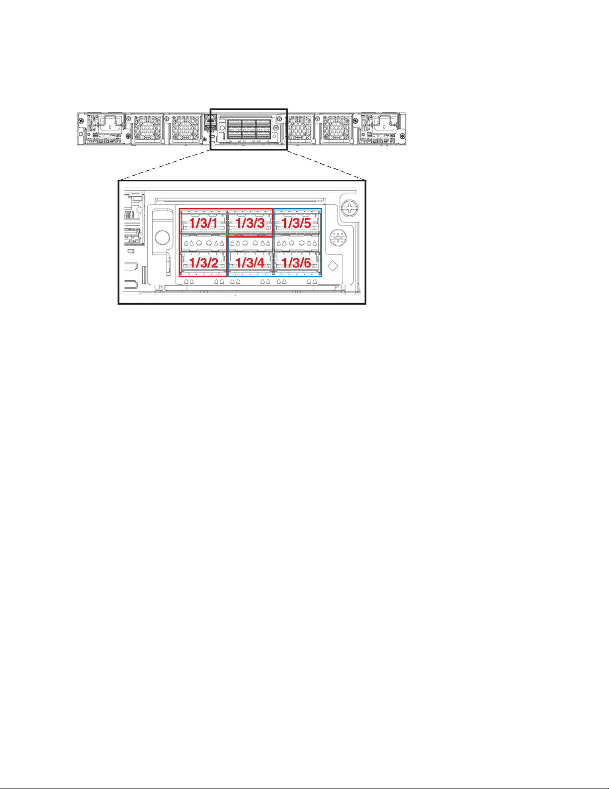
Stacking Brocade ICX 7750 switches
NOTE
FIGURE 21 Rear panel stacking ports
The available rear panel stacking ports are ports 1/3/1 through 1/3/6.
Unused stacking ports can be used as data ports. For example, you can elect to use only one default port as a stacking port and
use the other default port as a data port. Furthermore, when a Brocade ICX 7750-6Q stacking module is not configured for
stacking, its ports can be used as data ports.
A stack connection can also be a trunked link consisting of multiple ports, which increases stacking bandwidth and provides resiliency. Up
to two stack trunks are supported, and each trunk can include up to three ports.
Only ports that are in sequential order can be configured as a stacking trunk. A default port; that is, either port 1/2/1 or 1/2/4 in slot 2 or port
1/3/1 or 1/3/4 in slot 3, is always the first sequential port in a trunk.
Possible 3-port trunks:
• 1/2/1 to 1/2/3
• 1/2/4 to 1/2/6
• 1/3/1 to 1/3/3
• 1/3/4 to 1/3/6
Possible 2-port trunks:
• 1/2/1 to 1/2/2
• 1/2/4 to 1/2/5
• 1/3/1 to 1/3/2
• 1/3/4 to 1/3/5
Stacking configuration requirements
Before configuring the stack using the CLI, physically connect the devices using stacking cables. For information about configuring a
stack, refer to the FastIron Ethernet Switch Stacking Configuration Guide.
28 Brocade ICX 7750 Switch Hardware Installation Guide
53-1003900-02
Page 39

Stacking Brocade ICX 7750 switches
NOTE
Stacking cables
Use QSFP+ direct attached active copper stacking cables or QSFP+ fiber optic cables to connect Brocade ICX 7750 devices in a stack.
The copper cable lengths for 40 GbE ports are 1 meter, 3 meters, and 5 meters.
Extended distance stacking
Because Brocade ICX 7750 devices use Ethernet for the inter-switch stack connections, the deployment options are greatly increased. If
standard copper stacking cables are used, the inter-switch connections can be up to 5 meters, which is usually sufficient for locally
distributed stacks such as in top-of-rack (ToR) applications. For broader distribution, fiber-optic cables should be used, allowing a stack to
be deployed across multiple physical locations such as the wiring closets of an office building.
The use of 40GBASE-LR4 optics for extended distance stacking is supported only in the default stacking ports (1/2/1, 1/2/4, 1/3/1,
or 1/3/4). Due to the limitation on the Brocade ICX7750-48C and the ICX7750-48F, where 40GBASE-LR4 optics are supported
only in ports 1/2/5, 1/2/6, 1/3/5, or 1/3/6, extended distance stacking is not supported for 40GBASE-LR4 optics.
Table 7 shows the approved optics and stacking distance combinations.
TABLE 7 Fiber-optic options and stacking distances
Stacking cable option Description Maximum stacking distance
40GBase-SR4 fiber-optic cable 40G QSFP-QSFP 100 meter
40GBase-ESR4 fiber-optic cable 40G QSFP-QSFP 300 meter (OM3 multimode fiber)
400 meter (OM4 multimode fiber)
40GBase-LR4 fiber-optic cable 40G QSFP-QSFP 10 kilometers for ICX 7750-26Q device only
Stack size
The Brocade ICX 7750 supports up to 12 units in a stack. You can mix any number of Brocade ICX 7750-26Q, Brocade ICX 7750-48F,
or Brocade ICX 7750-48C devices together in a stack.
Stacking topologies
Both linear and ring topologies are supported in a stack. In a linear stack topology, there is a connection between each switch that carries
two-way communications across the stack.
For example, in a three-unit stack using a linear topology, unit 1 connects to unit 2, and unit 2 connects to unit 3.
Figure 22 shows a supported rear panel linear stacking topology.
Brocade ICX 7750 Switch Hardware Installation Guide 29
53-1003900-02
Page 40
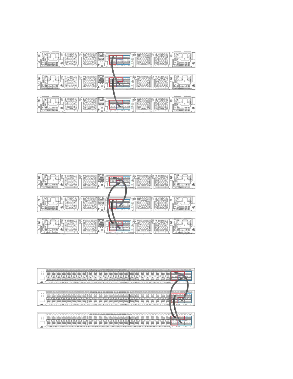
Stacking Brocade ICX 7750 switches
FIGURE 22 Rear panel linear stacking topology
In a ring stack topology, there is an extra connection between the logical first and last devices, forming a “ring” or “closed-loop.” The
closed-loop connection provides a redundant path for the stack link, so if one link fails, stack communications can be maintained.
For example, in a three-unit stack using a ring topology, unit 1 connects to unit 2, unit 2 connects to unit 3, and unit 3 connects to unit 1.
Figure 23 shows a supported rear panel ring stacking topology.
FIGURE 23 Rear panel ring stacking topology
Figure 24 shows a supported front panel ring stacking topology.
FIGURE 24 Front panel ring stacking topology
30 Brocade ICX 7750 Switch Hardware Installation Guide
53-1003900-02
Page 41
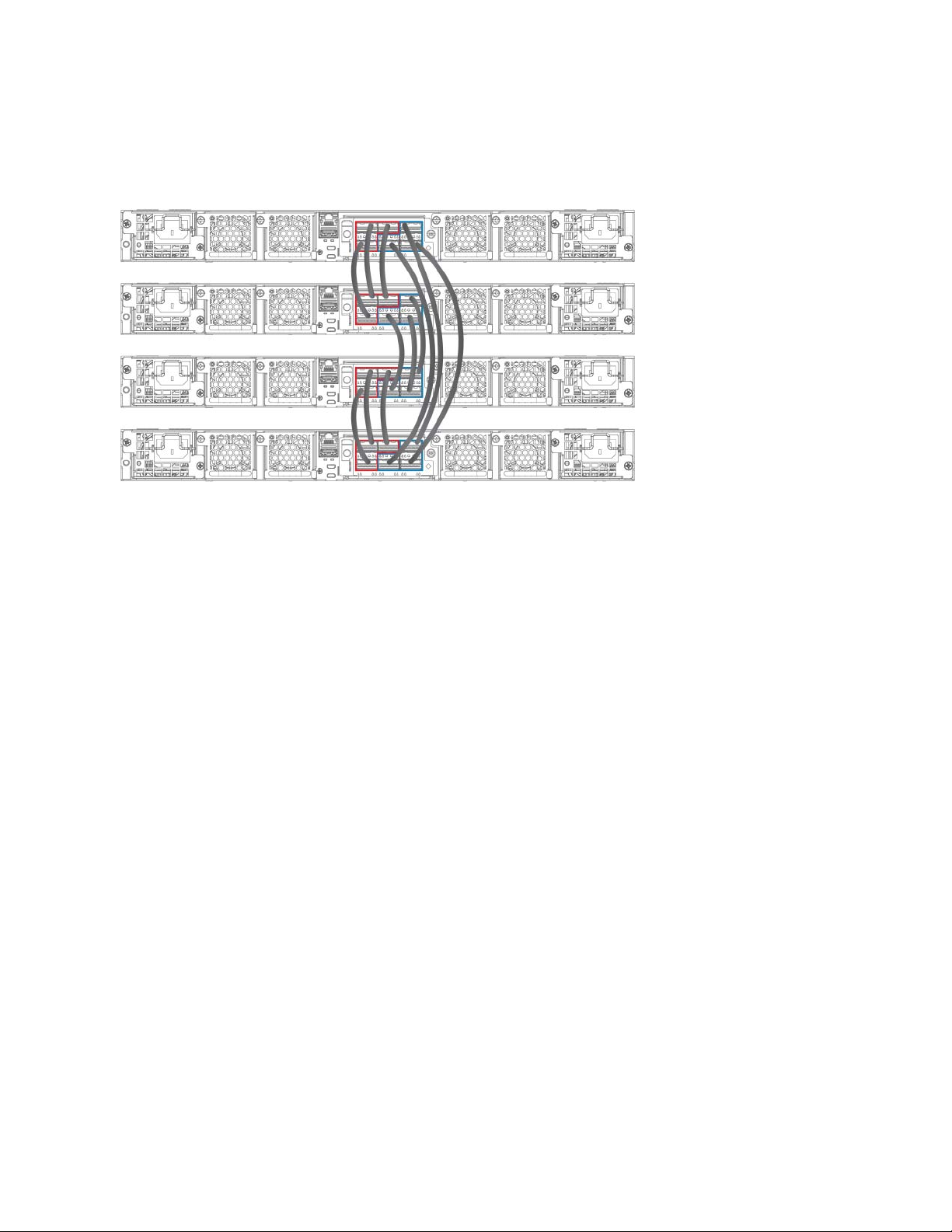
Figure 25 shows a supported rear panel ring trunk-stack topology.
NOTE
FIGURE 25 Rear panel ring trunk-stack topology
Stacking Brocade ICX 7750 switches
For more information about stacking, refer to the Brocade FastIron Stacking Configuration Guide.
Brocade ICX 7750 Switch Hardware Installation Guide 31
53-1003900-02
Page 42

Stacking Brocade ICX 7750 switches
32 Brocade ICX 7750 Switch Hardware Installation Guide
53-1003900-02
Page 43

Brocade ICX 7750 Operation
• LED activity interpretation . . . . . . . . . . . . . . . . . . . . . . . . . . . . . . . . . . . . . . . . . . . . . . . . . . . . . . . . . . . . . . . . . . . . . . . . . . . . . . . 33
• Brocade ICX 7750 front-panel LEDs. . . . . . . . . . . . . . . . . . . . . . . . . . . . . . . . . . . . . . . . . . . . . . . . . . . . . . . . . . . . . . . . . . . . . 33
• Brocade ICX 7750 rear-panel LEDs . . . . . . . . . . . . . . . . . . . . . . . . . . . . . . . . . . . . . . . . . . . . . . . . . . . . . . . . . . . . . . . . . . . . . 36
• LED patterns . . . . . . . . . . . . . . . . . . . . . . . . . . . . . . . . . . . . . . . . . . . . . . . . . . . . . . . . . . . . . . . . . . . . . . . . . . . . . . . . . . . . . . . . . . . 37
• Diagnostic tests and monitoring. . . . . . . . . . . . . . . . . . . . . . . . . . . . . . . . . . . . . . . . . . . . . . . . . . . . . . . . . . . . . . . . . . . . . . . . . . 40
LED activity interpretation
System activity and status can be determined through the activity of the LEDs on the switch.
There are three possible LED states: off (no light), a steady light, and a flashing light. Flashing lights may be slow, fast, or flickering. The
LED colors are either green or amber.
Sometimes, the LEDs flash either of the colors during boot, POST, or other diagnostic tests. This is normal; it does not indicate a problem
unless the LEDs do not indicate a healthy state after all boot processes and diagnostic tests are complete.
Brocade ICX 7750 front-panel LEDs
The Brocade ICX 7750-26Q has the following LEDs on the front panel:
• Two power supply unit (PSU) bicolor status LEDs (green and amber) labeled PSU1 and PSU2
• One DIAG LED bicolor status LED (green and amber)
• One MS LED bicolor status LED (green and amber)
• One HA LED bicolor status LED (green and amber)
• One RDNT LED bicolor status LED (green and amber)
• Four bicolor status LEDs (green and amber) for each of the 26 QSFP+ ports that indicate the status of the ports in 40 GbE
mode and 4x10 GbE breakout mode
Figure 26 shows the LEDs on the Brocade ICX 7750-26Q front panel.
Brocade ICX 7750 Switch Hardware Installation Guide 33
53-1003900-02
Page 44
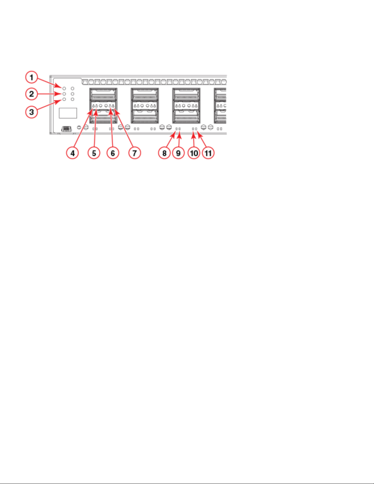
Brocade ICX 7750 front-panel LEDs
FIGURE 26 Brocade ICX 7750-26Q front-panel LEDs
1 PSU1 and PSU2 status LEDs
(PSU1 corresponds to the right power supply slot
on the rear panel and PSU2 corresponds to the left
power supply slot, as viewed from the rear)
3 MS and DIAG status LEDs 4 Lower slot 40 GbE mode link/activity LED or 10 GbE
5 HA and RDNT status LEDs 6 Lower slot 10 GbE mode lane 2 link/activity LED
7 Upper slot 40 GbE mode link/activity LED or
10 GbE mode lane 1 link/activity LED
9 Upper slot 10 GbE mode lane 2 link/activity LED 10 Lower slot 10 GbE mode lane 4 link/activity LED
11 Upper slot 10 GbE mode lane 3 link/activityy LED
The Brocade ICX 7750-48C has the following LEDs on the front panel:
2 Upper slot 10 GbE mode lane 4 link/activity LED
mode lane 1 link/activity LED
8 Lower slot 10 GbE mode lane 3 link/activity LED
• Two power supply unit (PSU) bicolor status LEDs (green and amber) labeled PSU1 and PSU2
• One DIAG LED bicolor status LED (green and amber)
• One MS LED bicolor status LED (green and amber)
• One HA LED bicolor status LED (green and amber)
• One RDNT LED bicolor status LED (green and amber)
• 48 1/10 GbE bicolor status LEDs (green for 10 GbE and amber for 1 GbE) which indicate 1 GbE or 10 GbE mode of operation
• Four bicolor status LEDs (green and amber) for each of the six QSFP+ ports that indicate the status of the ports in 40 GbE mode
and 4x10 GbE breakout mode
Figure 27 shows the LEDs on the Brocade ICX 7750-48C front panel. The up-arrow port status LEDs for the 1/10 GbE ports correspond
to the upper, odd-numbered ports; the down-arrow port status LEDs correspond to the lower, even-numbered ports.
34 Brocade ICX 7750 Switch Hardware Installation Guide
53-1003900-02
Page 45
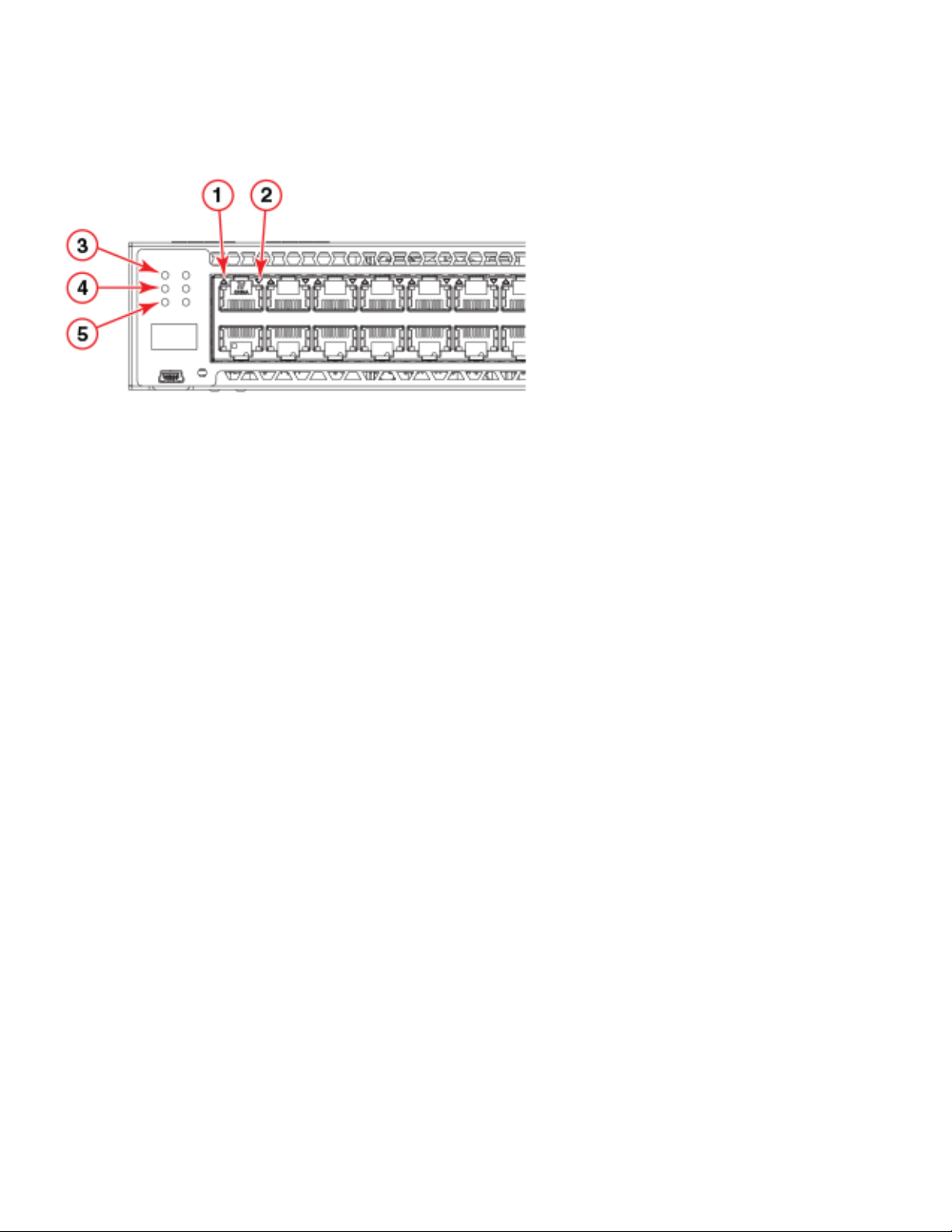
FIGURE 27 Brocade ICX 7750-48C front-panel LEDs
1 Upper 1/10 GbE port LEDs 2 MS and DIAG status LEDs
3 Lower 1/10 GbE port LEDs 4 HA and RDNT status LEDs
5 PSU1 and PSU2 status LEDs
(PSU1 corresponds to the right power supply slot
on the rear panel and PSU2 corresponds to the left
power supply slot, as viewed from the rear)
Brocade ICX 7750 front-panel LEDs
The Brocade ICX 7750-48F has the following LEDs on the front panel:
• Two power supply unit (PSU) bicolor status LEDs (green and amber) labeled PSU1 and PSU2
• One DIAG LED bicolor status LED (green and amber)
• One MS LED bicolor status LED (green and amber)
• One HA LED bicolor status LED (green and amber)
• One RDNT LED bicolor status LED (green and amber)
• 48 1/10 GbE SFP+ port bicolor status LEDs (green for 10 GbE and amber for 1 GbE) that indicate the 1 GbE or 10 GbE mode of
operation
• Four bicolor status LEDs (green and amber) for each of the six QSFP+ ports that indicate the status of the ports in 40 GbE mode
and 4x10 GbE breakout mode
Figure 28 shows the LEDs on the Brocade ICX 7750-48F front panel.
The up-arrow port status LEDs for the 10 GbE ports correspond to the upper, odd-numbered ports; the down-arrow port status LEDs
correspond to the lower, even-numbered ports.
Brocade ICX 7750 Switch Hardware Installation Guide 35
53-1003900-02
Page 46
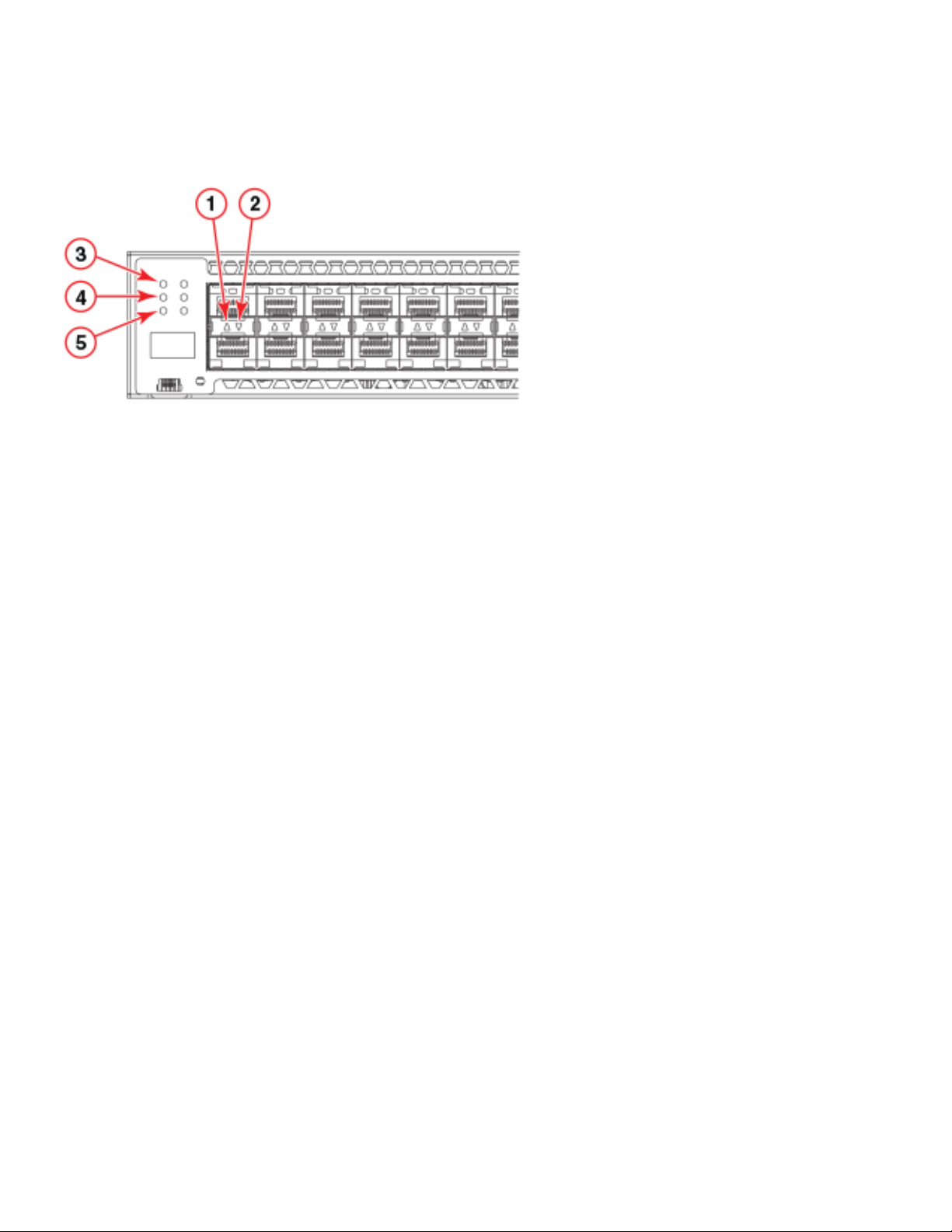
Brocade ICX 7750 rear-panel LEDs
FIGURE 28 Brocade ICX 7750-48F front-panel LEDs
1 Upper 1/10 GbE port LEDs 2 MS and DIAG status LEDs
3 Lower 1/10 GbE port LEDs 4 HA and RDNT status LEDs
5 PSU1 and PSU2 status LEDs
(PSU1 corresponds to the right power supply slot
on the rear panel and PSU2 corresponds to the left
power supply slot, as viewed from the rear)
Brocade ICX 7750 rear-panel LEDs
The Brocade ICX 7750 has the following LEDs on the rear panel:
• Two Management port status LEDs
• Two stack control path port LEDs (currently not used)
• Expansion module LEDs:
• One Power LED bicolor status LED (green and amber)
• Four bicolor status LEDs (green and amber) for each of the six QSFP+ ports that indicate the status of the ports in 40 GbE
mode and 4x10 GbE breakout mode
• Power supply LEDs: One status LED on each installed power supply
• Fan tray LEDs: One status LED on each installed fan tray
Figure 29 shows the LEDs on the rear panel of the Brocade ICX 7750.
36 Brocade ICX 7750 Switch Hardware Installation Guide
53-1003900-02
Page 47
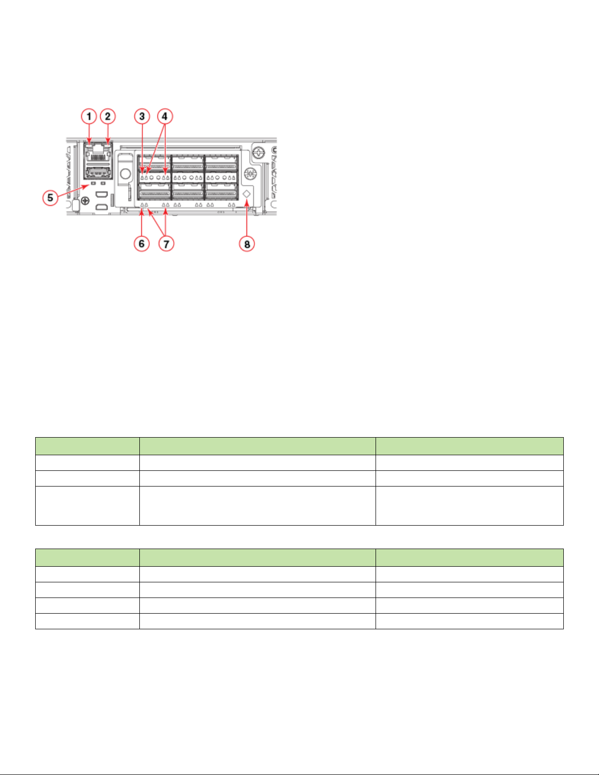
FIGURE 29 Brocade ICX 7750 rear-panel LEDs
1 Management port 10/100 Mbps link/activity LEDs 2 UP port (left) and DN port (right) link status LEDs
3 Management port 1000 Mbps link/activity LEDs 4 Lower slot 40 GbE mode link/activity LED or 10 GbE
mode lane 1 link/activity LEDs
5 Upper slot 40 GbE mode link/activity LED or
10 GbE mode lane 1 link/activity LEDs
7 Upper slot 10 GbE mode lanes 2, 3, and 4
link/activity LEDs
6 Lower slot 10 GbE mode lanes 2, 3, and 4
link/activity LEDs
8 Expansion module power LED
LED patterns
LED patterns
The following tables describe the Brocade ICX 7750 LED patterns.
TABLE 8 PSU1 and PSU2 LEDs
LED state Status of hardware Recommended action
Off (no light) System is off or there is no power. Verify the system is on and has completed booting.
Steady green PSU is on and functioning properly. No action required.
Steady amber PSU is missing power or in a faulty state. Verify that the PSU power cord is connected to a
functioning power source.
Replace power supply.
TABLE 9 DIAG LED
LED state Status of hardware Recommended action
Off (no light) Diagnostic is off. No action required.
Blinking green System self-diagnostic test is in progress. No action required.
Steady green System self-diagnostic test is successfully completed. No action required.
Steady amber System self-diagnostic test has detected a fault. Contact support.
Brocade ICX 7750 Switch Hardware Installation Guide 37
53-1003900-02
Page 48

LED patterns
TABLE 10 MS LED
LED state Status of hardware Recommended action
Off (no light) Stacking mode is enabled and the switch is a stack member, or the
switch is operating in standalone mode.
Steady green Stacking mode is enabled and the switch is the stack master. No action required.
Steady amber Stacking mode is enabled and the switch is in slave mode. No action required.
No action required.
TABLE 11 RDNT LED
LED state Status of hardware Recommended action
Off (no light) System does not have redundant fans or PSUs installed. No action required.
Steady green System is operating in redundant mode. No action required.
Steady amber System has redundant fans and PSUs, but software has disabled
redundant mode.
No action required.
TABLE 12 Management port left (link) status LED
LED state Status of hardware Recommended action
Off (no light) Not cabled. No action required.
Steady green A link is up. No action required.
TABLE 13 Management port right (activity) status LED
LED state Status of hardware Recommended action
Off (no light) Not cabled or no packets are being transmitted or received. No action required.
Blinking green There is traffic and packets are being transmitted or received. No action required.
TABLE 14 1/10 GbE RJ-45 port LEDs
LED state Status of hardware Recommended action
Off (no light) Not cabled. No action required.
Steady green Link is up in 10 GbE mode. No action required.
Blinking green There is 10 GbE traffic and packets are being transmitted or
received.
Steady amber Link is up in 1 GbE mode. No action required.
Blinking amber There is 1 GbE traffic and packets are being transmitted or
received.
No action required.
No action required.
TABLE 15 1/10 GbE SFP+ port LEDs
LED state Status of hardware Recommended action
Off (no light) Not cabled. No action required.
Steady green Link is up in 10 GbE mode. No action required.
Blinking green There is 10 GbE traffic and packets are being transmitted or
received.
Steady amber Link is up in 1 GbE mode. No action required.
Blinking amber There is 1 GbE traffic and packets are being transmitted or
received.
No action required.
No action required.
38 Brocade ICX 7750 Switch Hardware Installation Guide
53-1003900-02
Page 49

TABLE 16 40 GbE mode QSFP+ port LEDs (left-side LED)
LED state Status of hardware Recommended action
Off (no light) Not cabled. No action required.
Steady green Link is up in 40 GbE mode. No action required.
Blinking green There is 40 GbE traffic and packets are being transmitted or
received.
No action required.
TABLE 17 4x10 GbE mode QSFP+ port LEDs
LED state Status of hardware Recommended action
Off (no light) Not cabled. No action required.
Steady amber Port lane link is up in 10 GbE mode. No action required.
Blinking amber There is 10 GbE traffic and packets are being transmitted or
received.
No action required.
TABLE 18 10/100/1000 Mbps UP and DN Ethernet port LEDs
LED state Status of hardware Recommended action
Off (no light) Not cabled. No action required.
Steady green Link is up in 1 GbE mode. No action required.
Blinking green There is 1 GbE traffic and packets are being transmitted or
received.
Steady amber Link is up in 10/100 Mbps mode. No action required.
Blinking amber There is 10/100 Mbps traffic and packets are being transmitted or
received.
No action required.
No action required.
LED patterns
TABLE 19 Power supply unit LED
LED state Status of hardware Recommended action
Off (no light) PSU is not powered on. Verify that the PSU power cord is connected to a
functioning power source.
Steady green PSU is on and functioning properly. No action required.
Blinking green
(with power cord connected)
Steady amber PSU has no DC output. Replace the power supply.
External AC input parameters are within an acceptable range but
there is no DC output or it is disabled.
Replace the power supply.
TABLE 20 Expansion module power LED
LED state Status of hardware Recommended action
Off (no light) Module is not powered on. No action required.
Steady green Module is on and functioning properly. No action required.
Steady amber Module is on and booting up. No action required.
TABLE 21 Fan tray LED
LED state Status of hardware Recommended action
Off (no light) Fan tray is not powered on. No action required.
Brocade ICX 7750 Switch Hardware Installation Guide 39
53-1003900-02
Page 50

Diagnostic tests and monitoring
TABLE 21 Fan tray LED (Continued)
LED state Status of hardware Recommended action
Steady green Fan tray is on and functioning properly. No action required.
Steady amber Fan tray has nonfunctioning fans. Replace fan tray.
Diagnostic tests and monitoring
Brocade FastIron software includes diagnostic tests to help you troubleshoot the hardware. System diagnostic software is designed to
fulfill the purpose of offline diagnostics. In offline diagnostics, you must turn the diagnostic flags on or off to execute diagnostic tests
during the next bootup.
The CLI commands for system diagnostic tests are dm diag and dm alt-diag. These diagnostic tests verify all available hardware
components including:
• I2C devices
• EEPROMS
• CPU packet
• Test MAC alignment
• Line rate
During system diagnostic testing, the system is completely under the control of the diagnostic software. All hardware components are
verified, and results are displayed on the console. In cases where a failure is detected, results and corrective actions will be displayed. After
the system diagnostic testing is complete, the system exits from the diagnostic mode and reloads the system for normal operation.
System diagnostic testing runs at link speeds 10 Gbps and 40 Gbps (QSFP+ ports) depending on the speed of the link being tested and
the type of port.
40 Brocade ICX 7750 Switch Hardware Installation Guide
53-1003900-02
Page 51

Managing the Brocade ICX 7750
CAUTION
• Temperature threshold levels . . . . . . . . . . . . . . . . . . . . . . . . . . . . . . . . . . . . . . . . . . . . . . . . . . . . . . . . . . . . . . . . . . . . . . . . . . . . . 41
• Hardware maintenance schedule. . . . . . . . . . . . . . . . . . . . . . . . . . . . . . . . . . . . . . . . . . . . . . . . . . . . . . . . . . . . . . . . . . . . . . . . . . 41
• Replacing a copper or fiber-optic module. . . . . . . . . . . . . . . . . . . . . . . . . . . . . . . . . . . . . . . . . . . . . . . . . . . . . . . . . . . . . . . . . . 41
• FRU removal and replacement procedures . . . . . . . . . . . . . . . . . . . . . . . . . . . . . . . . . . . . . . . . . . . . . . . . . . . . . . . . . . . . . . . 43
• Replacing a power supply unit . . . . . . . . . . . . . . . . . . . . . . . . . . . . . . . . . . . . . . . . . . . . . . . . . . . . . . . . . . . . . . . . . . . . . . . . . . . 44
• Replacing fan trays. . . . . . . . . . . . . . . . . . . . . . . . . . . . . . . . . . . . . . . . . . . . . . . . . . . . . . . . . . . . . . . . . . . . . . . . . . . . . . . . . . . . . . 45
• Replacing an expansion module . . . . . . . . . . . . . . . . . . . . . . . . . . . . . . . . . . . . . . . . . . . . . . . . . . . . . . . . . . . . . . . . . . . . . . . . . 47
The procedures in this chapter are for qualified service personnel.
Temperature threshold levels
The fan speed settings are set by the Brocade ICX 7750, and are not configurable.
Hardware maintenance schedule
Brocade ICX 7750 switch hardware components require minimal maintenance. Brocade recommends cleaning the fiber-optic
connectors on a fiber-optic port and the connected fiber cable each time you disconnect the cable.
Replacing a copper or fiber-optic module
You can remove an SFP+, or QSFP+ transceiver from a slot and replace it with a new one while the Brocade ICX 7750 is powered on and
running.
This section provides information about the following tasks:
• Removing a copper or fiber-optic module
• Cabling a fiber-optic module
• Cleaning the fiber-optic connectors
Removing a copper or fiber-optic module
While removing a copper or fiber-optic module, be sure to wear an ESD wrist strap that is connected to ground.
Before removing a fiber-optic transceiver, have the following items available:
• The protective covering that you removed from the fiber-optic transceiver port when you initially installed the module.
• An ESD wrist strap with a plug for connection to the ESD connector on the router chassis.
Brocade ICX 7750 Switch Hardware Installation Guide 41
53-1003900-02
Page 52

Replacing a copper or fiber-optic module
NOTE
NOTE
NOTE
NOTE
CAUTION
DANGER
For safety reasons, the ESD wrist strap should contain a series 1 megohm resistor.
Laser radiation. Do not view directly with optical instruments. Class 1M laser products.
When 10 GbE fiber-optic ports on the Brocade ICX 7750 are disabled, the laser light remains on even though the port link is down.
To remove a copper or fiber-optic module from a transceiver slot, do the following.
1. Put on the ESD wrist strap and ground yourself by attaching the clip end to a metal surface (such as an equipment rack).
2. Disconnect the copper or fiber cable connector from the port connector.
3. Unlock the copper or fiber-optic module by pulling the bail latch forward, away from the front panel of the module.
On 1000Base-SX ports, the bail latch is enclosed in a black sleeve, and on 1000Base-LX ports, the bail latch is enclosed in a blue
sleeve.
The bail latch may be attached to either the top or the bottom of the SFP+, or QSFP+ transceiver.
4. Grasp the bail latch and pull the copper or fiber-optic module out of the port.
5. Store the copper or fiber-optic module in a safe, static-free place or in an anti-static bag.
6. Install a new copper or fiber-optic module in the port.
Cabling a fiber-optic module
Use the following steps to cable a fiber-optic transceiver.
1. Remove the protective covering from the fiber-optic port connectors and store the covering for future use.
Before cabling a fiber-optic transceiver, Brocade strongly recommends cleaning the cable connectors and the port connectors.
For more information, refer to “Cleaning the fiber-optic connectors” on page 42.
2. Gently insert the cable connector (a tab on each connector should face upward) into the transceiver connector until the tabs lock
into place.
3. Observe the link and active LEDs to determine if the network connections are functioning properly.
Cleaning the fiber-optic connectors
To avoid problems with the connection between the fiber-optic transceiver (SFP+, or QSFP+) and the fiber cable connectors, Brocade
strongly recommends cleaning both connectors each time you disconnect and reconnect them. Dust can accumulate in the connectors
and cause problems such as reducing the optic launch power.
42 Brocade ICX 7750 Switch Hardware Installation Guide
53-1003900-02
Page 53
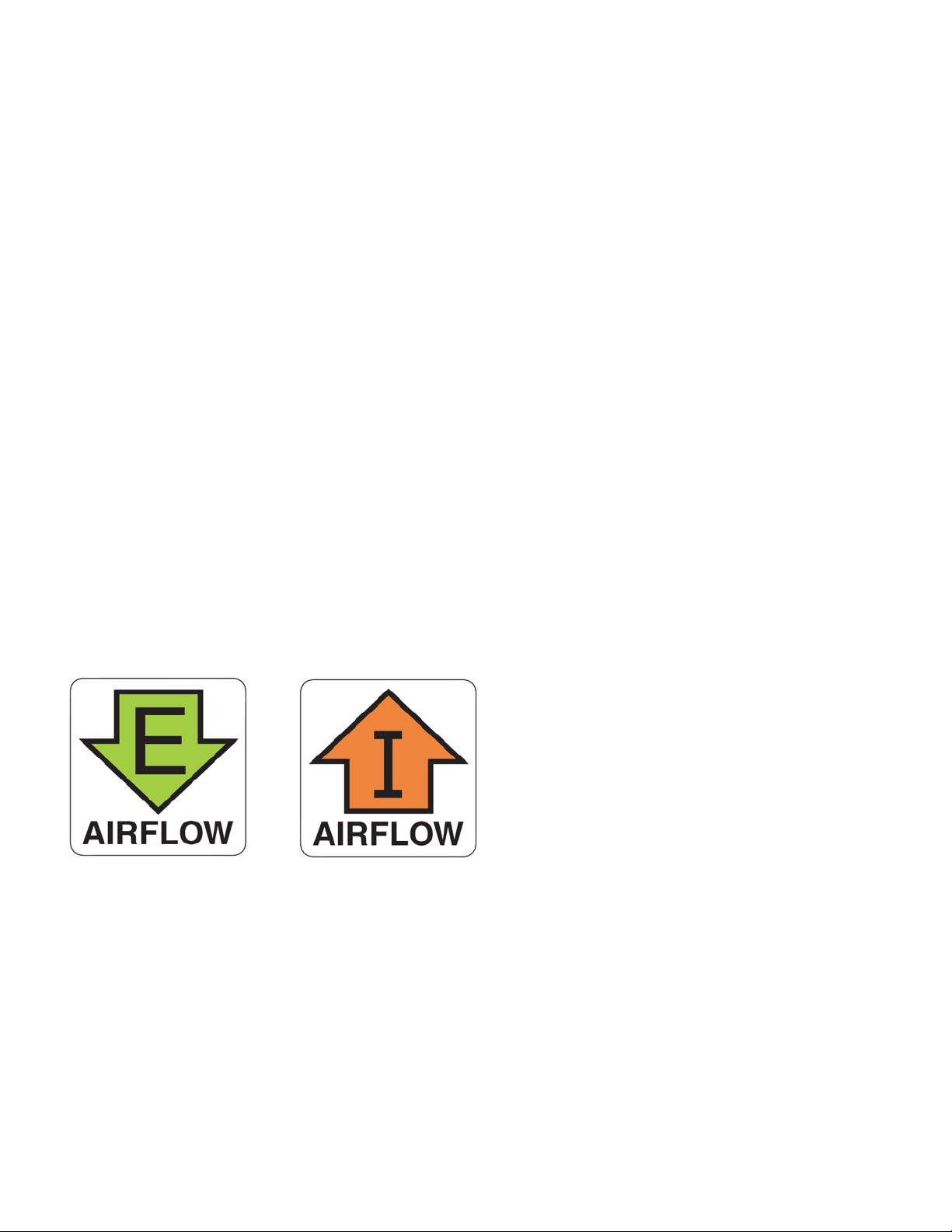
FRU removal and replacement procedures
NOTE
To clean the fiber cable connectors, Brocade recommends using a fiber-optic reel-type cleaner. When not using an SFP+, or QSFP+
connector, make sure to keep the protective covering in place.
FRU removal and replacement procedures
The field-replaceable units (FRUs) in the Brocade ICX 7750 can be removed and replaced by using a #1 Phillips screwdriver. The
switches can continue operating during the FRU replacement if the conditions specified in these procedures are followed. This covers
both the power supply unit (PSU) FRUs and fan FRUs.
This document describes how to change FRUs for units with either an air intake or air exhaust. You must replace a failed FRU with
a FRU of the same type. This applies to both power supplies and fans. A new FRU must have the same part number (P/N) as the
FRU being replaced. The manufacturing P/N is located on the top of the FRU.
If a mismatched power source or fan tray is installed by mistake, a warning is sent to the console. The warning messages will be similar to
the following:
• For a fan mismatch: [WARNING, Brocade ICX 7750, MISMATCH in Fan Air Flow direction. Replace FRU with fan air flows in the
same direction.
• For a power supply: [WARNING, Brocade ICX 7750, MISMATCH in PSU Air Flow direction. Replace PSU with air flows in the
same direction
You can use external labels as a guide. The power supplies and fan trays are labeled with an airflow symbol on the faceplate to indicate
whether the assembly takes in or exhausts air. The symbol also appears on the top of the FRU. All FRUs in a chassis must have the same
label affixed so that airflow direction is consistent. Figure 30 illustrates examples of the airflow labels.
FIGURE 30 Examples of airflow symbols
The green E symbol indicates an exhaust FRU. This unit pulls air in from the front of the switch and exhausts it out the rear side. This is
called front-to-back airflow or forward airflow.
The orange I symbol indicates an intake FRU. This unit pulls air in from the rear side of the switch and exhausts it out the front side. This is
called back-to-front airflow or reverse airflow.
The show chassis command displays a device’s airflow direction: Front-to-Back or Back-to-Front.
Brocade ICX 7750 Switch Hardware Installation Guide 43
53-1003900-02
Page 54
Replacing a power supply unit
NOTE
CAUTION
CAUTION
CAUTION
CAUTION
Replacing a power supply unit
Remove the power cord from a power supply before you install it in or remove it from the device. Otherwise, the power supply
or the device could be damaged as a result. (The device can be running while a power supply is being installed or removed,
but the power supply itself should not be connected to a power source.)
For the Brocade ICX 7750 devices, be sure that the airflow direction of the power supply unit matches that of the installed fan
tray. The power supplies and fan trays are clearly labeled with either a green arrow with an “E”, or an orange arrow with an “I.”
Maintain all power supply and fan trays in operational condition to provide redundancy.
Because the cooling system relies on pressurized air, do not leave any of the power supply and fan tray slots empty longer
than two minutes while the switch is operating. If a power supply or fan tray fails, leave it in the switch until it can be replaced.
Disassembling any part of the power supply and fan tray voids the warranty and regulatory certifications. There are no
user-serviceable parts inside the power supply and fan tray.
Table 19 on page 39 describes the Brocade ICX 7750 power supply status LED colors, behaviors, and actions required, if any.
Determining the need to replace a power supply
Use one of the following methods to determine the status of the power supplies:
• Check the PSU1 and PSU2 LEDs on the switch front panel or power supply status LED (refer to “LED patterns” on page 37).
• Enter the show chassis command at the prompt to display power supply status.
Time and items required
Replacing a power supply in the Brocade ICX 7750 should take less than two minutes to complete.
You need the following items to replace a power supply in a Brocade ICX 7750:
• A new power supply (must have the same part number and the same airflow label as the power supply being replaced)
• A #1 Phillips screwdriver
Replacing a power supply
Complete the following steps to replace a power supply in a Brocade ICX 7750.
44 Brocade ICX 7750 Switch Hardware Installation Guide
53-1003900-02
Page 55

Replacing fan trays
NOTE
NOTE
NOTE
CAUTION
CAUTION
1. To leave the Brocade ICX 7750 in service while replacing a power supply, verify that the other power supply (the one not being
replaced) has been powered on for at least four seconds and has a steady green status LED.
2. Before opening the package that contains the power supply, touch the bag to the switch casing to discharge any potential static
electricity. Brocade recommends using an ESD wrist strap during installation.
3. Remove the power supply from the anti-static shielded bag.
4. Ensure that the replacement power supply has the same part number and airflow label as the power supply being replaced.
5. Unplug the power cord from the power supply that is being replaced.
6. Using the Phillips screwdriver, unscrew the two captive screws on the power supply.
7. Remove the power supply from the chassis by pulling the handle on the power supply out and away from the chassis.
Do not force the installation. If the power supply does not slide in easily, ensure that the power supply is correctly oriented before
continuing.
8. Holding the power supply level, guide it into the carrier rails on each side and gently push it all the way into the slot, ensuring that
it firmly engages with the connector.
9. When you are sure the power supply has properly engaged the connector, tighten the retainer screws to secure the power supply
in the slot.
10. Plug the power cord into the power supply to power on the unit.
The power supply will immediately attempt to power up.
11. Verify that the LED on the new power supply displays steady green while the Brocade ICX 7750 is operating. If the LED is not
steady green, ensure that the power supply is securely installed and seated properly. Alternatively, check the PSU1 and PSU2
LEDs on the switch front panel (refer to “LED patterns” on page 37).
You can enter the show chassis command at the command line prompt to display power supply status.
Replacing fan trays
For the Brocade ICX 7750 devices, be sure that the airflow direction of the fan tray matches thatof the installed power supply
unit. The power supplies and fan trays are clearly labeled with either a green arrow with an “E”, or an orange arrow with an “I.”
The Brocade ICX 7750 includes four redundant, hot-swappable fan units. However, it can run on one power supply and three fans. In that
case, the empty power supply and fan slot must be covered using the filler panels.
Maintain all power supply and fan trays in operational condition to provide redundancy.
Because the cooling system relies on pressurized air, do not leave any of the power supply and fan tray slots empty longer
than two minutes while the switch is operating. If a power supply or fan tray fails, leave it in the switch until it can be replaced.
Brocade ICX 7750 Switch Hardware Installation Guide 45
53-1003900-02
Disassembling any part of the power supply and fan tray voids the warranty and regulatory certifications. There are no
user-serviceable parts inside the power supply and fan tray.
Page 56

Replacing fan trays
NOTE
NOTE
CAUTION
Determining the need to replace a fan tray
Enter the show chassis command in the command line interface to display fan status.
Time and items required
Replacing a fan tray in the Brocade ICX 7750 should take less than two minutes to complete.
You need the following items to replace a fan tray in the Brocade ICX 7750:
• A new fan tray (must have the same part number and the same airflow label as the fan tray being replaced; refer to Figure 30 on
page 43 for the location of the airflow label)
• A #1 Phillips screwdriver
Installing or replacing the fan tray
Complete the following steps to install or replace a fan tray in a Brocade ICX 7750.
1. If replacing a fan tray:
a. Using a Phillips screwdriver, unscrew the captive screw on the fan tray.
b. Remove the fan tray from the chassis by pulling the handle on the fan tray out and away from the chassis.
c. Ensure that the replacement fan tray has the same part number and airflow label as the fan tray being replaced.
2. If installing a new fan tray into a slot covered with a filler panel:
a. Using a Phillips screwdriver, unscrew the captive screw on the filler panel.
b. Remove the filler panel.
3. Before opening the package that contains the new fan tray, touch the bag to the switch casing to discharge any potential static
electricity. It is recommended that you wear an ESD wrist strap during installation.
4. Remove the fan tray from the anti-static shielded bag.
Do not force the installation. If the fan tray does not slide in easily, ensure that it is correctly oriented before continuing.
5. Holding the fan tray level, guide it into the carrier rails on each side and gently push it all the way into the slot, ensuring that it
firmly engages with the connector.
6. When you are sure the fan tray has properly engaged the connector, tighten the captive screw to secure the fan tray in the slot.
The fans are controlled automatically by the device.
7. Verify correct installation by running the show chassis command.
If you do not install a power supply in a slot, you must keep the slot panel in place. If you run the device with an uncovered slot,
the system will overheat.
46 Brocade ICX 7750 Switch Hardware Installation Guide
53-1003900-02
Page 57

Replacing an expansion module
NOTE
NOTE
CAUTION
Replacing an expansion module
The Brocade ICX 7750 includes a rear-panel slot for a 6-port QSFP+ 40 GbE expansion module. If not installed, the empty expansion
module slot must be covered using the filler panel.
Disassembling any part of the expansion module voids the warranty and regulatory certifications. There are no
user-serviceable parts inside the expansion module assembly.
Time and items required
Replacing an expansion module in the Brocade ICX 7750 should take less than two minutes to complete.
You need the following items to replace an expansion module in the Brocade ICX 7750:
• A new expansion module
• A #1 Phillips screwdriver
Installing or replacing an expansion module
The Brocade ICX 7750 must be powered off before installing or replacing an expansion module.
Complete the following steps to install or replace an expansion module in the Brocade ICX 7750.
1. If replacing an expansion module:
a. Pull the release latch lever on the module into its open position.
b. Using a Phillips screwdriver, unscrew the two captive screws on the expansion module.
c. Remove the expansion module from the chassis by pulling the handle on the expansion module out and away from the
chassis.
2. If installing a new expansion module into a slot covered with a filler panel:
a. Using a Phillips screwdriver, unscrew the captive screws on the filler panel.
b. Remove the filler panel.
3. Before opening the package that contains the new expansion module, touch the bag to the switch casing to discharge any
potential static electricity. It is recommended that you wear an ESD wrist strap during installation.
4. Remove the expansion module from the anti-static shielded bag.
Do not force the installation. If the expansion module does not slide in easily, ensure that it is correctly oriented before continuing.
5. Holding the expansion module level, guide it into the carrier rails on each side and gently push it all the way into the slot, ensuring
that it firmly engages with the connector.
Brocade ICX 7750 Switch Hardware Installation Guide 47
53-1003900-02
6. When you are sure the expansion module has properly engaged the connector, tighten the captive screws to secure the
expansion module in the slot.
7. Push the release latch lever on the module into its closed position.
8. Verify correct installation by running the show chassis command.
Page 58

Replacing an expansion module
CAUTION
If you do not install a power supply in a slot, you must keep the slot panel in place. If you run the device with an uncovered slot,
the system will overheat.
48 Brocade ICX 7750 Switch Hardware Installation Guide
53-1003900-02
Page 59

Brocade ICX 7750 Specifications
• System specifications . . . . . . . . . . . . . . . . . . . . . . . . . . . . . . . . . . . . . . . . . . . . . . . . . . . . . . . . . . . . . . . . . . . . . . . . . . . . . . . . . . . 49
• Ethernet. . . . . . . . . . . . . . . . . . . . . . . . . . . . . . . . . . . . . . . . . . . . . . . . . . . . . . . . . . . . . . . . . . . . . . . . . . . . . . . . . . . . . . . . . . . . . . . . 49
• LEDs . . . . . . . . . . . . . . . . . . . . . . . . . . . . . . . . . . . . . . . . . . . . . . . . . . . . . . . . . . . . . . . . . . . . . . . . . . . . . . . . . . . . . . . . . . . . . . . . . . 50
• Other . . . . . . . . . . . . . . . . . . . . . . . . . . . . . . . . . . . . . . . . . . . . . . . . . . . . . . . . . . . . . . . . . . . . . . . . . . . . . . . . . . . . . . . . . . . . . . . . . . 50
• Weight and physical dimensions . . . . . . . . . . . . . . . . . . . . . . . . . . . . . . . . . . . . . . . . . . . . . . . . . . . . . . . . . . . . . . . . . . . . . . . . . 50
• Environmental requirements. . . . . . . . . . . . . . . . . . . . . . . . . . . . . . . . . . . . . . . . . . . . . . . . . . . . . . . . . . . . . . . . . . . . . . . . . . . . . 50
• Power supply specifications (per PSU) . . . . . . . . . . . . . . . . . . . . . . . . . . . . . . . . . . . . . . . . . . . . . . . . . . . . . . . . . . . . . . . . . . . . 51
• Power consumption (typical configuration). . . . . . . . . . . . . . . . . . . . . . . . . . . . . . . . . . . . . . . . . . . . . . . . . . . . . . . . . . . . . . . . . 51
• Power consumption (maximum configuration) . . . . . . . . . . . . . . . . . . . . . . . . . . . . . . . . . . . . . . . . . . . . . . . . . . . . . . . . . . . . 52
• Power consumption (modules). . . . . . . . . . . . . . . . . . . . . . . . . . . . . . . . . . . . . . . . . . . . . . . . . . . . . . . . . . . . . . . . . . . . . . . . . . . 52
• Data port specifications (Ethernet). . . . . . . . . . . . . . . . . . . . . . . . . . . . . . . . . . . . . . . . . . . . . . . . . . . . . . . . . . . . . . . . . . . . . . . . 52
• Serial port specifications (pinout mini-USB). . . . . . . . . . . . . . . . . . . . . . . . . . . . . . . . . . . . . . . . . . . . . . . . . . . . . . . . . . . . . . . 52
• Serial port specifications (pinout RJ-45) . . . . . . . . . . . . . . . . . . . . . . . . . . . . . . . . . . . . . . . . . . . . . . . . . . . . . . . . . . . . . . . . . . 53
• Serial port specifications (protocol) . . . . . . . . . . . . . . . . . . . . . . . . . . . . . . . . . . . . . . . . . . . . . . . . . . . . . . . . . . . . . . . . . . . . . . . 53
• Memory specifications . . . . . . . . . . . . . . . . . . . . . . . . . . . . . . . . . . . . . . . . . . . . . . . . . . . . . . . . . . . . . . . . . . . . . . . . . . . . . . . . . . 53
• Regulatory compliance (EMC) . . . . . . . . . . . . . . . . . . . . . . . . . . . . . . . . . . . . . . . . . . . . . . . . . . . . . . . . . . . . . . . . . . . . . . . . . . . 53
• Regulatory compliance (safety) . . . . . . . . . . . . . . . . . . . . . . . . . . . . . . . . . . . . . . . . . . . . . . . . . . . . . . . . . . . . . . . . . . . . . . . . . . 54
• Regulatory compliance (environmental). . . . . . . . . . . . . . . . . . . . . . . . . . . . . . . . . . . . . . . . . . . . . . . . . . . . . . . . . . . . . . . . . . . 54
System specifications
TABLE 22 System specifications
System component Description
Enclosure 1U; stackable chassis mountable in a standard 2 or 4-post rack
Power supplies Dual, redundant, hot-swappable 504 W AC or DC with intake or exhaust airflow
Fans Four redundant, hot-swappable fan units with intake or exhaust airflow
Cooling Forced-air cooling front-to-back or back-to-front
System architecture Nonblocking shared memory switch
ICX 7750-26Q: 26 10/40 GbE QSFP+ ports
ICX 7750-48F: 48 1/10 GbE SFP+ ports and six 10/40 GbE QSFP+ ports
ICX 7750-48C: 48 1/10 GbE RJ-45 ports and six 10/40 GbE QSFP+ ports
System processors System processor 1.5 GHz Freescale P2041
Ethernet
TABLE 23 Ethernet specifications
System component Description
SFP GbE ports 40/10/1 GbE optical and copper
Ethernet management port 1
Brocade ICX 7750 Switch Hardware Installation Guide 49
53-1003900-02
Page 60
LEDs
LEDs
TABLE 24 LED specifications
System component Description
Switch status and management Nine LED states to indicate switch and module status (green and amber)
Port status Five LED states to indicate port status (green and amber)
Other
TABLE 25 Other specifications
System component Description
Serial cable Mini-USB to RJ-45
RJ-45 to DB9 adapter 1
Stack Control-Path Cable Two Micro-HDMI to RJ-45 (currently not used)
Control-Path Cable Holder Kit One cable holder and one screw
Weight and physical dimensions
TABLE 26 Weight and physical dimensions
Model Height Width Depth Empty weight Fully loaded weight
ICX 7750-26Q 4.37 cm
1.72 in
ICX 7750-48F 4.37 cm
1.72 in
ICX 7750-48C 4.37 cm
1.72 in
44.00 cm
17.32 in
44.00 cm
17.32 in
44.00 cm
17.32 in
40.64 cm
16.00 in
40.64 cm
16.00 in
43.10 cm
16.97 in
5.60 kg
12.30 lb
5.90 kg
13.00 lb
7.00 kg
15.40 lb
8.80 kg
19.40 lb
9.10 kg
20.10 lb
10.20 kg
22.50 lb
Environmental requirements
TABLE 27 Environmental requirements
Condition Operational Non-operational
Ambient temperature ICX 7750-26Q: -5º to 50ºC (23º to 122ºF)
ICX 7750-48F: -5º to 50ºC (23º to 122ºF)
ICX 7750-48C: -5º to 40ºC (23º to 104ºF)
Relative humidity (non-condensing) ICX 7750-26Q and ICX 7750-48F:
10% to 90% at 50ºC (122ºF)
ICX 7750-48C:
10% to 90% at 40ºC (104ºF)
Altitude (above sea level) 0 to 3000 m (10,000 feet) 12,000 m (39,000 feet)
Shock 20 G, 11 ms, half-sine wave 30 G, 11 ms, half-sine wave
Vibration 1 G sine, 0.4 grms random, 5-500 Hz 2.4 G sine, 1.12 grms random, 5-500 Hz
-40º to 60ºC (-40º to 140ºF)
10% to 90% at 60ºC (140ºF)
50 Brocade ICX 7750 Switch Hardware Installation Guide
53-1003900-02
Page 61
Power supply specifications (per PSU)
TABLE 27 Environmental requirements (Continued)
Condition Operational Non-operational
Airflow ICX 7750-26Q:
Back-to-Front: Maximum. - 55 cfm, Typical - 25 cfm
Front-to-Back: Maximum. - 62 cfm, Typical - 29 cfm
ICX 7750-48F:
Back-to-Front: Maximum. - 55 cfm, Typical - 25 cfm
Front-to-Back: Maximum. - 61 cfm, Typical - 29 cfm
ICX 7750-48C:
Back-to-Front: Maximum. - 55 cfm, Typical - 32 cfm
Front-to-Back: Maximum. - 62 cfm, Typical - 36 cfm
Heat dissipation Refere to Table 29 on page 51 and Table 30 on page 52. N/A
N/A
Power supply specifications (per PSU)
TABLE 28 Power supply specifications (per PSU)
Power
supply
model
RPS9 504 W 100-240 VAC (nominal)
RPS9DC 504 W -48 VDC (nominal)
Maximum
output power
rating (DC)
Input voltage Input line frequency Maximum
input
current
100-264 VAC (range)
-40 to -60 VDC (range)
50/60 Hz (nominal)
47 – 63 Hz (range)
NA 15 A -Ve fused 25 A peak cold or warm start for <10 ms
7 A Line fused 30 A peak cold or warm start for <10 ms
Input line
protection
Maximum inrush current
10 A peak for cycles 10 ms – 150 ms
Less than fuse rating for >150 ms
Less than 15 A after 150 ms
Power consumption (typical configuration)
All ports linked and up. 50% traffic with 64-byte packets. Fans at normal speed.
TABLE 29 Power consumption (typical configuration)
Model name @100 VAC input @200 VAC input @-48 VDC input Minimum number of
ICX 7750-26Q 277 W
945 BTU/hr
ICX 7750-48F 254 W
867 BTU/hr
ICX 7750-48C 510 W
1740 BTU/hr
Brocade ICX 7750 Switch Hardware Installation Guide 51
53-1003900-02
274 W
935 BTU/hr
250 W
853 BTU/hr
511 W
1744 BTU/hr
274 W
935 BTU/hr
250 W
853 BTU/h
511 W
1744 BTU/hr
power supplies
1 AC or DC Fan speed is at nominal.
1 AC or DC Fan speed is at nominal.
1 AC or DC Fan speed is at nominal.
Notes
Page 62

Power consumption (maximum configuration)
Power consumption (maximum configuration)
All ports connected with optics to draw maximum power per MSA Optics Specification. Traffic at full rate or 100% throughput. Fans at full
speed.
TABLE 30 Power consumption (maximum configuration)
Model name @100 VAC input @200 VAC input @-48 VDC input Minimum number of
power supplies
Notes
ICX 7750-26Q 319 W
1088 BTU/hr
ICX 7750-48F 290 W
989 BTU/hr
ICX 7750-48C 558 W
1904 BTU/hr
350 W
1194 BTU/hr
327 W
1116 BTU/hr
586 W
2000 BTU/hr
350 W
1194 BTU/hr
327 W
1116 BTU/hr
586 W
2000 BTU/hr
1 AC or DC Fans at high speed
1 AC or DC Fans at high speed
1 AC or DC Fans at high speed
Power consumption (modules)
TABLE 31 Power consumption (modules)
Module name Module description Power consumption
ICX 7750-6Q 6-port 10/40 GbE QSFP+ Typical = 18.8 W
Maximum = 25.9 W
Data port specifications (Ethernet)
TABLE 32 Data port specifications (Ethernet)
Model Port type Number of ports Description
ICX 7750-26Q 40 GbE 26 QSFP+, 10/40 Gbps, compatible with short range (SR) and long range (LR) optical SFP
ICX 7750-48F 40 GbE 6 QSFP+, 10/40 Gbps, compatible with short range (SR) and long range (LR) optical SFP
10 GbE 48 SFP+, 1/10 Gbps, compatible with short range (SR) and long range (LR) optical SFP
ICX 7750-48C 40 GbE 6 QSFP+, 10/40 Gbps, compatible with short range (SR) and long range (LR) optical SFP
10 GbE 48 10GBASE-T, 1/10 Gbps, capable of auto-negotiating link speed.
transceivers.
transceivers.
transceivers.
transceivers.
Serial port specifications (pinout mini-USB)
TABLE 33 Serial port specifications (pinout mini-USB)
Pin Signal Description
1 Reserved Not used
2UART0_RX Data received by ICX
3 UART0_TX Data transmitted by ICX
52 Brocade ICX 7750 Switch Hardware Installation Guide
53-1003900-02
Page 63
TABLE 33 Serial port specifications (pinout mini-USB)
Pin Signal Description
4 Reserved Not used
5 GND Ground
Serial port specifications (pinout RJ-45)
TABLE 34 Serial port specifications (pinout RJ-45)
Pin Signal Description
1 Not supported N/A
2 Not supported N/A
3 UART1_TXD Transmit data to ICX
4 GND Logic ground
5 Not supported N/A
6 UART1_RXD Receive data from ICX
7 Not supported N/A
8 Not supported N/A
Serial port specifications (pinout RJ-45)
Serial port specifications (protocol)
TABLE 35 Serial port specifications (protocol)
Parameter Value
Baud 9600
Data bits 8
Parity None
Stop bits 1
Flow control None
Memory specifications
TABLE 36 Memory specifications
Memory Type Size
Main memory DDR3 8 GB
Boot Flash NOR Flash 64 MB
eUSB Drive USB 2 GB
Regulatory compliance (EMC)
• FCC Part 15, Subpart B (Class A)
• EN 55022 (CE mark) (Class A)
Brocade ICX 7750 Switch Hardware Installation Guide 53
53-1003900-02
Page 64

Regulatory compliance (safety)
• EN 55024 (CE mark) (Immunity) for Information Technology Equipment
• ICES-003 (Canada) (Class A)
• AS/NZ 55022 (Australia) (Class A)
• VCCI (Japan) (Class A)
• EN 61000-3-2
• EN 61000-3-3
• EN 61000-6-1
Regulatory compliance (safety)
• CAN/CSA-C22.2 No. 60950/UL 60950 - Safety of Information Technology Equipment
• EN 60825 Safety of Laser Products - Part 1: Equipment Classification, Requirements and User’s Guide
• EN 60950/IEC 60950 Safety of Information Technology Equipment
Regulatory compliance (environmental)
• 2014/35/EU and 2014/30/EU
• 2011/65/EU – Restriction of the use of certain hazardous substance in electrical and electronic equipment (EU RoHS)
• 2012/19/EU – Waste electrical and electronic equipment (EU WEEE)
• 94/62/EC – packaging and packaging waste (EU)
• 2006/66/EC – batteries and accumulators and waste batteries and accumulators (EU battery directive)
• 1907/2006 of the European Parliament and of the Council of 18 December 2006 concerning the Registration, Evaluation,
Authorisation and Restriction of Chemicals (EU REACH)
• Section 1502 of the Dodd-Frank Wall Street Reform and Consumer Protection Act of 2010 – U.S. Conflict Minerals
• 30/2011/TT-BCT – Vietnam circular
• SJ/T 11363-2006 Requirements for Concentration Limits for Certain Hazardous Substances in EIPs (China)
• SJ/T 11364-2006 Marking for the Control of Pollution Caused by EIPs (China)
54 Brocade ICX 7750 Switch Hardware Installation Guide
53-1003900-02
Page 65

Brocade ICX 7750 Regulatory
NOTE
Statements
• USA (FCC CFR 47 Part 15 Warning) . . . . . . . . . . . . . . . . . . . . . . . . . . . . . . . . . . . . . . . . . . . . . . . . . . . . . . . . . . . . . . . . . . . . . 55
• Industry Canada statement . . . . . . . . . . . . . . . . . . . . . . . . . . . . . . . . . . . . . . . . . . . . . . . . . . . . . . . . . . . . . . . . . . . . . . . . . . . . . . 55
• Europe and Australia (CISPR 22 Class A Warning) . . . . . . . . . . . . . . . . . . . . . . . . . . . . . . . . . . . . . . . . . . . . . . . . . . . . . . . . 55
• Germany (Noise Warning) . . . . . . . . . . . . . . . . . . . . . . . . . . . . . . . . . . . . . . . . . . . . . . . . . . . . . . . . . . . . . . . . . . . . . . . . . . . . . . . 55
• Japan (VCCI) . . . . . . . . . . . . . . . . . . . . . . . . . . . . . . . . . . . . . . . . . . . . . . . . . . . . . . . . . . . . . . . . . . . . . . . . . . . . . . . . . . . . . . . . . . . 56
• Korea . . . . . . . . . . . . . . . . . . . . . . . . . . . . . . . . . . . . . . . . . . . . . . . . . . . . . . . . . . . . . . . . . . . . . . . . . . . . . . . . . . . . . . . . . . . . . . . . . . 56
• China . . . . . . . . . . . . . . . . . . . . . . . . . . . . . . . . . . . . . . . . . . . . . . . . . . . . . . . . . . . . . . . . . . . . . . . . . . . . . . . . . . . . . . . . . . . . . . . . . . 57
• BSMI statement (Taiwan). . . . . . . . . . . . . . . . . . . . . . . . . . . . . . . . . . . . . . . . . . . . . . . . . . . . . . . . . . . . . . . . . . . . . . . . . . . . . . . . 58
USA (FCC CFR 47 Part 15 Warning)
This equipment has been tested and found to comply with the limits for a Class A digital device pursuant to Part 15 of the FCC Rules.
These limits are designed to provide reasonable protection against harmful interference when the equipment is operated in a commercial
environment. This equipment generates, uses, and can radiate radio frequency energy and, if not installed and used in accordance with the
instruction manual, may cause harmful interference to radio communications. Operation of this equipment in a residential area is likely to
cause harmful interference in which case the user will be required to correct the interference at his own expense.
Changes or modifications made to this device which are not expressly approved by Brocade could void the user’s authority to
operate the equipment.
Industry Canada statement
Cet appareil numérique de la classe A est conforme à la norme NMB-003 du Canada.
English translation of above statement
This Class A digital apparatus complies with Canadian ICES-003.
Europe and Australia (CISPR 22 Class A Warning)
This is a Class A product. In a domestic environment this product may cause radio interference in which case the user may be required to
take adequate measures.
Germany (Noise Warning)
Maschinenlärminformations-Verordnung - 3. GPSGV, der höchste Schalldruckpegel beträgt 53.0 dB(A) gemäss EN ISO 7779.
English translation of above statement
Machine noise information regulation - 3. GPSGV, the highest sound pressure level value is 53.0 dB(A) in accordance with EN ISO 7779.
Brocade ICX 7750 Switch Hardware Installation Guide 55
53-1003900-02
Page 66
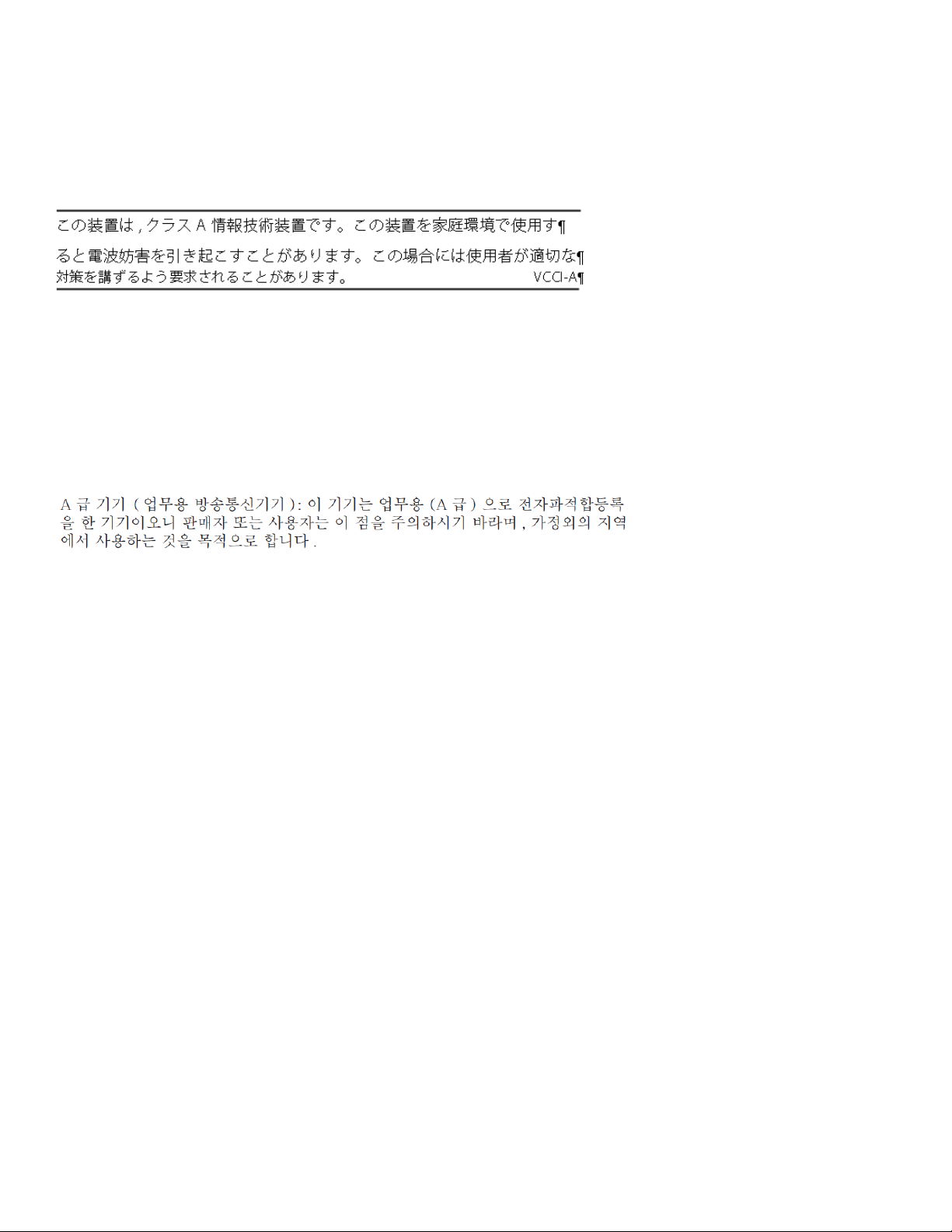
Japan (VCCI)
Japan (VCCI)
English translation of above statement
This is Class A product based on the standard of the Voluntary Control Council For Interference by Information Technology Equipment
(VCCI). If this equipment is used in a domestic environment, radio disturbance may arise. When such trouble occurs, the user may be
required to take corrective actions.
Korea
English translation of above statement
Class A device (Broadcasting Communication Device for Office Use): This device obtained EMC registration for office use (Class A), and
may be used in places other than home. Sellers and/or users need to take note of this.
56 Brocade ICX 7750 Switch Hardware Installation Guide
53-1003900-02
Page 67
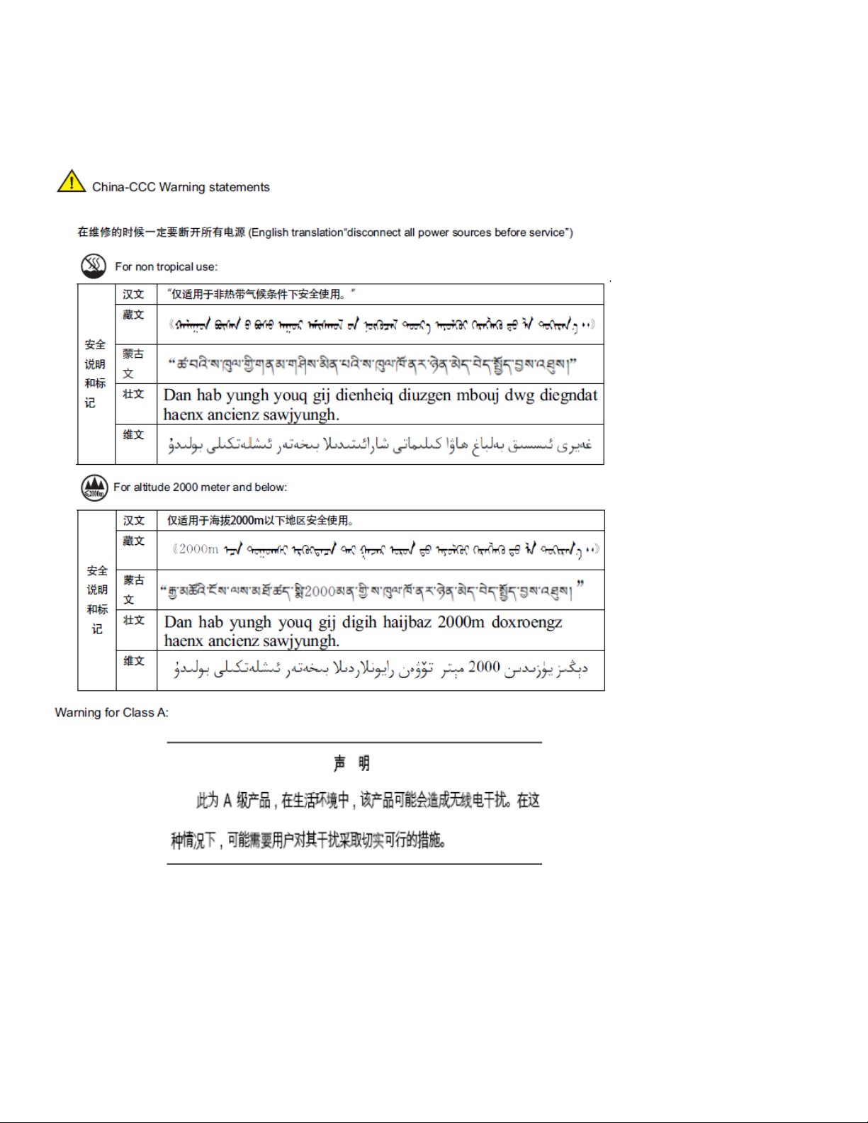
China
China
English translation of above statement
This is a Class A product. In a domestic environment this product may cause radio interference, inwhich case the user may be required to
take adequate measures.
Brocade ICX 7750 Switch Hardware Installation Guide 57
53-1003900-02
Page 68

BSMI statement (Taiwan)
BSMI statement (Taiwan)
English translation of above statement
Warning: This is a class A product. In a domestic environment this product may cause radio interference in which case the user may be
required to take adequate measures.
58 Brocade ICX 7750 Switch Hardware Installation Guide
53-1003900-02
Page 69

Brocade ICX 7750 Cautions and Danger Notices
• Cautions . . . . . . . . . . . . . . . . . . . . . . . . . . . . . . . . . . . . . . . . . . . . . . . . . . . . . . . . . . . . . . . . . . . . . . . . . . . . . . . . . . . . . . . . . . . . . . . 59
• Danger notices . . . . . . . . . . . . . . . . . . . . . . . . . . . . . . . . . . . . . . . . . . . . . . . . . . . . . . . . . . . . . . . . . . . . . . . . . . . . . . . . . . . . . . . . . 63
Cautions
A caution calls your attention to a possible hazard that can damage equipment.
“Vorsicht” weist auf die Gefahr einer möglichen Beschädigung des Gerätes hin.
Une mise en garde attire votre attention sur un risque possible d'endommagement de l'équipement. Ci-dessous, vous trouverez les mises
en garde utilisées dans ce manuel.
Un mensaje de precaución le advierte sobre un posible peligro que pueda dañar el equipo. Las siguientes son precauciones utilizadas en
este manual.
CAUTION The procedures in this manual are for qualified service personnel.
VORSICHT Die Verfahren in diesem Handbuch sind nur für qualifiziertes Wartungspersonal gedacht.
MISE EN GARDE Les procédures décrites dans ce manuel doivent être effectuées par le personnel de service qualifié uniquement.
PRECAUCIÓN Los procedimientos de este manual se han hecho para personal de servicio cualificado.
CAUTION All devices with DC power supplies (Brocade ICX 7750 ) are intended for installation in restricted access areas only. A restricted
VORSICHT Alle Geräte mit Gleichstromeingangsschaltung (Brocade ICX 7750 ) sind nur zur Installation in Sperrbereichen bestimmt. Ein
MISE EN GARDE Tous les équipements dotés d'un bloc d'alimentation en courant continu (Brocade ICX 7750 ) sont conçus pour l'installation
PRECAUCIÓN Todos aquellos dispositivos con fuentes de alimentación de CC (Brocade ICX 7750 ) están diseñados para su instalación en
CAUTION Do not install the device in an environment where the operating ambient temperature might exceed 50° C (122° F).
VORSICHT Das Gerät darf nicht in einer Umgebung mit einer Umgebungsbetriebstemperatur von über 50° C (122° F) installiert werden.
MISE EN GARDE N'installez pas le dispositif dans un environnement où la température d'exploitation ambiante risque de dépasser 50° C (122° F).
PRECAUCIÓN No instale el instrumento en un entorno en el que la temperatura ambiente de operación pueda exceder los 50° C (122° F).
access area is where access can be gained only by service personnel through the use of a special tool, lock and key, or other
means of security, and is controlled by the authority responsible for the location.
Sperrbereich ist ein Ort, zu dem nur Wartungspersonal mit einem Spezialwerkzeug, Schloss und Schlüssel oder einer anderen
Schutzvorrichtung Zugang hat. Er unterliegt außerdem der Kontrolle durch die für den Standort verantwortliche Stelle.
dans des zones à accès réglementé uniquement. Une zone à accès réglementé est un local qui n'est accessible que par le
personnel d'entretien à l'aide d'un outil, verrou ou clé conçus à cet effet, ou de tout autre accessoire de sécurité, et qui est
contrôlé par l'autorité responsable de ce local.
zonas de acceso restringido solamente. Una zona de acceso restringido es un lugar al que sólo puede acceder personal de
mantenimiento haciendo uso de una herramienta especial, una llave y un candado, o algún otro medio de seguridad, y que está
controlado por la autoridad responsable.
Brocade ICX 7750 Switch Hardware Installation Guide 59
53-1003900-02
Page 70

Cautions
CAUTION Make sure the airflow around the front, sides, and back of the device is not restricted.
VORSICHT Stellen Sie sicher, dass an der Vorderseite, den Seiten und an der Rückseite der Luftstrom nicht behindert wird.
MISE EN GARDE Vérifiez que rien ne restreint la circulation d'air devant, derrière et sur les côtés du dispositif et qu'elle peut se faire librement.
PRECAUCIÓN Asegúrese de que el flujo de aire en las inmediaciones de las partes anterior, laterales y posterior del instrumento no esté
CAUTION Use a separate branch circuit for each AC power cord, which provides redundancy in case one of the circuits fails.
VORSICHT Es empfiehlt sich die Installation eines separaten Stromkreiszweiges für jede Wechselstrom-Elektroschnur als Redundanz im
MISE EN GARDE Utilisez un circuit de dérivation différent pour chaque cordon d’alimentation C.A. Ainsi, il y aura un circuit redondant en cas de
PRECAUCIÓN Use un circuito derivado separado para cada cordón de alimentación de CA, con lo que se proporcionará redundancia en caso
CAUTION Ensure that the device does not overload the power circuits, wiring, and over-current protection. To determine the possibility of
VORSICHT Stromkreise, Verdrahtung und Überlastschutz dürfen nicht durch das Gerät überbelastet werden. Addieren Sie die
MISE EN GARDE Assurez-vous que le dispositif ne risque pas de surcharger les circuits d'alimentation, le câblage et la protection de surintensité.
PRECAUCIÓN Verifique que el instrumento no sobrecargue los circuitos de corriente, el cableado y la protección para sobrecargas. Para
restringido.
Fall des Ausfalls eines Stromkreises.
panne d’un des circuits.
de que uno de los circuitos falle.
overloading the supply circuits, add the ampere (amp) ratings of all devices installed on the same circuit as the device. Compare
this total with the rating limit for the circuit. The maximum ampere ratings are usually printed on the devices near the input power
connectors.
Nennstromleistung (in Ampere) aller Geräte, die am selben Stromkreis wie das Gerät installiert sind. Somit können Sie
feststellen, ob die Gefahr einer Überbelastung der Versorgungsstromkreise vorliegt. Vergleichen Sie diese Summe mit der
Nennstromgrenze des Stromkreises. Die Höchstnennströme (in Ampere) stehen normalerweise auf der Geräterückseite neben
den Eingangsstromanschlüssen.
Pour déterminer le risque de surcharge des circuits d'alimentation, additionnez l'intensité nominale (ampères) de tous les
dispositifs installés sur le même circuit que le dispositif en question. Comparez alors ce total avec la limite de charge du circuit.
L'intensité nominale maximum en ampères est généralement imprimée sur chaque dispositif près des connecteurs d'entrée
d'alimentation.
determinar la posibilidad de sobrecarga en los circuitos de suministros, añada las capacidades nominales de corriente (amp) de
todos los instrumentos instalados en el mismo circuito que el instrumento. Compare esta suma con el límite nominal para el
circuito. Las capacidades nominales de corriente máximas están generalmente impresas en los instrumentos, cerca de los
conectores de corriente de entrada.
CAUTION Never leave tools inside the chassis.
VORSICHT Lassen Sie keine Werkzeuge im Chassis zurück.
MISE EN GARDE Ne laissez jamais d'outils à l'intérieur du châssis.
PRECAUCIÓN No deje nunca herramientas en el interior del chasis.
60 Brocade ICX 7750 Switch Hardware Installation Guide
53-1003900-02
Page 71

Cautions
CAUTION Remove the power cord from a power supply before you install it in or remove it from the device. Otherwise, the power supply
VORSICHT Nehmen Sie vor dem Anschließen oder Abtrennen des Geräts das Stromkabel vom Netzteil ab. Ansonsten könnten das
MISE EN GARDE Enlevez le cordon d'alimentation d'un bloc d'alimentation avant de l'installer ou de l'enlever du dispositif. Sinon, le bloc
PRECAUCIÓN Retire el cordón de corriente del suministro de corriente antes de instalarlo o retírarlo del instrumento. De no hacerse así, el
CAUTION For the ICX 7750 devices, be sure that the airflow direction of the power supply unit matches that of the installed fan tray. The
VORSICHT Vergewissern Sie sich bei den ICX 7750-Geräten, dass die Luftstromrichtung des Netzteils der der eingebauten Lüftereinheit
MISE EN GARDE Pour les équipements de type ICX 7750, veillez à ce que le sens de circulation de l'air du bloc d'alimentation corresponde à celui
PRECAUCIÓN En el caso de dispositivos ICX 7750, asegúrese de que la dirección del flujo de aire de la unidad de alimentación se
or the device could be damaged as a result. (The device can be running while a power supply is being installed or removed, but
the power supply itself should not be connected to a power source.)
Netzteil oder das Gerät beschädigt werden. (Das Gerät kann während des Anschließens oder Annehmens des Netzteils laufen.
Nur das Netzteil sollte nicht an eine Stromquelle angeschlossen sein.)
d'alimentation ou le dispositif risque d'être endommagé. (Le dispositif peut être en train de fonctionner lorsque vous installez ou
enlevez un bloc d'alimentation, mais le bloc d'alimentation lui-même ne doit pas être connecté à une source d'alimentation.)
suministro de corriente o el instrumento podrían resultar dañados. (El instrumento puede estar encendido mientras se instala o
retira un suministro de corriente, pero el suministro de corriente en sí no deberá conectado a la corriente).
power supplies and fan trays are clearly labeled with either a green arrow with an "E", or an orange arrow with an "I."
entspricht. Die Netzteile und Lüftereinheiten sind eindeutig mit einem grünen Pfeil und dem Buchstaben "E" oder einem
orangefarbenen Pfeil mit dem Buchstaben "I" gekennzeichnet.
du tiroir de ventilation installé. Les blocs d'alimentation et les tiroirs de ventilation sont étiquetés d'une flèche verte avec un " E "
ou d'une flèche orange avec un " I ".
corresponda con la de la bandeja del ventilador instalada. Los dispositivos de alimentación y las bandejas del ventilador están
etiquetadas claramente con una flecha verde y una "E" o con una flecha naranja y una "I".
CAUTION For the ICX 7750 devices, be sure that the airflow direction of the fan tray matches that of the installed power supply unit. The
power supplies and fan trays are clearly labeled with either a green arrow with an "E", or an orange arrow with an "I."
VORSICHT Vergewissern Sie sich bei den ICX 7750-Geräten, dass die Luftstromrichtung der Lüftereinheit der des eingebauten Netzteils
entspricht. Die Netzteile und Lüftereinheiten sind eindeutig mit einem grünen Pfeil und dem Buchstaben "E" oder einem
orangefarbenen Pfeil mit dem Buchstaben "I" gekennzeichnet.
MISE EN GARDE Pour les équipements de type ICX 7750, veillez à ce que le sens de circulation de l'air du tiroir de ventilation corresponde à celui
du bloc d'alimentation installé. Les blocs d'alimentation et les tiroirs de ventilation sont étiquetés d'une flèche verte avec un " E "
ou d'une flèche orange avec un " I ".
PRECAUCIÓN En el caso de dispositivos ICX 7750, asegúrese de que la dirección del flujo de aire de la bandeja del ventilador se corresponda
con la de la unidad de alimentación. Los dispositivos de alimentación y las bandejas del ventilador están etiquetadas claramente
con una flecha verde y una "E" o con una flecha naranja y una "I".
CAUTION If you do not install a power supply in a slot, you must keep the slot panel in place. If you run the device with an uncovered
the system will overheat.
VORSICHT Wenn Sie in einem Einschub kein Netzteil einsetzen, müssen Sie die Blende im Einschub lassen. Der Betrieb des Geräts mit
einem offenen Einschub kann zur Überhitzung des Systems führen.
MISE EN GARDE Si vous n'installez pas de bloc d'alimentation dans un emplacement, vous devez laisser le cache de protection en place. Si vous
faites fonctionner l’équipement avec un emplacement vide, sans cache, le système risque de surchauffer.
PRECAUCIÓN Si no hay ninguna fuente de alimentación instalada en una ranura, debe dejar la tapa correspondiente puesta en la ranura. Si
pone en funcionamiento el dispositivo con una ranura descubierta, el sistema se sobrecalentará.
slot,
Brocade ICX 7750 Switch Hardware Installation Guide 61
53-1003900-02
Page 72

Cautions
CAUTION For the DC input circuit to the system of a Brocade ICX 7750, make sure there is a UL-Listed 20 Amp circuit breaker, minimum
VORSICHT Bei der Gleichstromeingangsschaltung zum System eines Brocade ICX 7750, muss sichergestellt werden, dass an den
MISE EN GARDE Pour le circuit d'alimentation en courant continu du système Brocade ICX 7750, vérifier la présence d'un disjoncteur bipolaire
PRECAUCIÓN Para el circuito de entrada de CC al sistema de un Brocade ICX 7750, verifique que existe un disyuntor catalogado por UL de
CAUTION Before plugging a cable to any port, be sure to discharge the voltage stored on the cable by touching the electrical contacts to
VORSICHT Bevor Sie ein Kabel in einen Anschluss einstecken, entladen Sie jegliche im Kabel vorhandene elektrische Spannung, indem Sie
MISE EN GARDE Avant de brancher un câble à un port, assurez-vous de décharger la tension du câble en reliant les contacts électriques à la terre.
PRECAUCIÓN Antes de conectar un cable en cualquier puerto, asegúrese de descargar la tensión acumulada en el cable tocando la superficie
CAUTION For DC systems, use grounding wire of at least 12 American Wire Gauge (AWG). The grounding wire should be attached to the
VORSICHT Für Gleichstromsystem verwenden Erdungskabel von mindestens 12AWG (3.31 mm2) (amerikanische Norm für
MISE EN GARDE Pour les systèmes d'alimentation courant continu (C.C), utilisez un fil de mise à terre d'au moins de 12 AWG (ou 3.31mm2). Le fil
PRECAUCIÓN Para el sistema CC, utilice un cable de tierra de al menos 12 AWG (Ancho de cable de EEUU). El cable de tierra debe estar
60 VDC, double pole, on the input lugs to the power supply. The input wiring for connection to the product should be Listed
copper wire, 12 AWG, marked VW-1, and rated minimum 90°C.
Eingangskabelschuhen zur Stromversorgung ein zweipoliger Schalter mit UL-Zulassung, 20 Ampere und mindestens 60 V
Gleichstrom vorhanden ist. Die Eingangsleitung zum Anschluss an das Produkt sollte als Kupferdraht, 12 AWG, angegeben, als
VW-1 gekennzeichnet und für mindestens 90°C bemessen sein.
homologué de 20 A, minimum 60 VCC, sur l'entrée de l'alimentation. Les câbles d'alimentation du produit doivent être des fils
de cuivre homologués de section 2.1 mm² (12 AWG), marqués VW-1 et testés à 90°C.
20 amperios, 60 VCC como mínimo, bipolar, en las orejetas de entrada a la fuente de alimentación. El cableado de entrada
para la conexión al producto deberá ser de cable de cobre catalogado, 12 AWG, marcado con VW-1, y tener una capacidad
nominal mínima para 90°C.
ground surface.
mit den elektrischen Kontakten eine geerdete Oberfläche berühren.
de conexión a tierra con los contactos eléctricos.
DC input connector (as shown in Figure 18); the other end connects to the building ground.
Drahtquerschnitte). Der Erdungsdraht sollte DC-Eingang angeschlossen werden (wie in Figure 18 zeigen #14), das andere Ende
verbindet sich mit dem Baugrund.
de mise à terre doit être relié au connecteur du circuit d'alimentation (voir Figure 18); l'autre extrémité se connecte à la prise terre
du batiment.
acoplado al conector de entrada de CC (según se muestra en la Figure 18); el otro extremo se conecta al suelo del edificio.
CAUTION Power supplies are hot-swappable. However, they should be inserted or removed without a power cord being connected to a
VORSICHT Netzteile sind hot-swap-fähig. Sie sollten jedoch eingesetzt oder entfernt werden, ohne dass ein Stromkabel mit einer
MISE EN GARDE Les unités d’alimentation sont permutables à chaud. Cependant, et pour éviter tout dommage, elles doivent être insérées ou
PRECAUCIÓN Los proveedores de energía son deslizables por calor. Sin embargo deben insertarse o extraerse sin ningún cable de
CAUTION For safety reasons, the ESD wrist strap should contain a series 1 megaohm resistor.
VORSICHT Aus Sicherheitsgründen sollte ein EGB-Armband zum Schutz von elektronischen gefährdeten Bauelementen mit einem 1
MISE EN GARDE Pour des raisons de sécurité, la dragonne ESD doit contenir une résistance de série 1 méga ohm.
PRECAUCIÓN Por razones de seguridad, la correa de muñeca ESD deberá contener un resistor en serie de 1 mega ohmio.
62 Brocade ICX 7750 Switch Hardware Installation Guide
power source to avoid damage.
Stromquelle verbunden ist, um Beschädigungen zu vermeiden.
retirées sans cordon d’alimentation relié à une source d’alimentation.
alimentación conectado a la fuente de alimentación para evitar daños.
Megaohm-Reihenwiderstand ausgestattet sein.
53-1003900-02
Page 73

Danger notices
Danger notices
A danger notification calls your attention to a possible hazard that can cause injury or death. The following are the warnings used in this
manual.
"Gefahr" weist auf eine mögliche Gefährdung hin, die zu Verletzungen oder Tod führen können. Sie finden die folgenden Warnhinweise in
diesem Handbuch.
Un danger attire votre attention sur un risque possible de blessure ou de décès. Ci-dessous, vous trouverez les avertissements utilisés
dans ce manuel.
Una señal de peligro le llama la atención sobre cualquier posible peligro que pueda ocasionar daños personales o la muerte. A
continuación se dan las advertencias utilizadas en este manual.
DANGER Risk of explosion if battery is replaced by an incorrect type. Dispose of used batteries according to the manufacturer’s
instructions.
GEFAHR Es besteht Explosionsgefahr, wenn ein unzulässiger Batterietyp eingesetzt wird. Verbrauchte Batterien sind entsprechend den
geltenden Vorschriften zu entsorgen.
DANGER Risque d'explosion en cas de remplacement de la pile par un modèle incorrect. Débarrassezvous des piles usagées
conformément aux instructions.
PELIGRO Riesgo de explosión si se sustituye la batería por una de tipo incorrecto. Deshágase de las baterías usadas de acuerdo con las
instrucciones.
DANGER Make sure the rack or cabinet housing the device is adequately secured to prevent it from becoming unstable or falling over.
GEFAHR Stellen Sie sicher, dass das Gestell oder der Schrank für die Unterbringung des Geräts auf angemessene Weise gesichert ist, so
dass das Gestell oder der Schrank nicht wackeln oder umfallen kann.
DANGER Vérifiez que le bâti ou le support abritant le dispositif est bien fixé afin qu'il ne devienne pas instable ou qu'il ne risque pas de
tomber.
PELIGRO Verifique que el bastidor o armario que alberga el instrumento está asegurado correctamente para evitar que pueda hacerse
DANGER Disconnect the power cord from all power sources to completely remove power from the device.
GEFAHR Ziehen Sie das Stromkabel aus allen Stromquellen, um sicherzustellen, dass dem Gerät kein Strom zugeführt wird.
DANGER Débranchez le cordon d'alimentation de toutes les sources d'alimentation pour couper complètement l'alimentation du
PELIGRO Para desconectar completamente la corriente del instrumento, desconecte el cordón de corriente de todas las fuentes de
inestable o que caiga.
dispositif.
corriente.
Brocade ICX 7750 Switch Hardware Installation Guide 63
53-1003900-02
Page 74

Danger notices
DANGER If the installation requires a different power cord than the one supplied with the device, make sure you use a power cord
displaying the mark of the safety agency that defines the regulations for power cords in your country. The mark is your
assurance that the power cord can be used safely with the device.
GEFAHR Falls für die Installation ein anderes Stromkabel erforderlich ist (wenn das mit dem Gerät gelieferte Kabel nicht passt), müssen
Sie sicherstellen, dass Sie ein Stromkabel mit dem Siegel einer Sicherheitsbehörde verwenden, die für die Zertifizierung von
Stromkabeln in Ihrem Land zuständig ist. Das Siegel ist Ihre Garantie, dass das Stromkabel sicher mit Ihrem Gerät verwendet
werden kann.
DANGER Si l'installation nécessite un cordon d'alimentation autre que celui fourni avec le dispositif, assurez-vous d'utiliser un cordon
d'alimentation portant la marque de l'organisation responsable de la sécurité qui définit les normes et régulations pour les
cordons d'alimentation dans votre pays. Cette marque vous assure que vous pouvez utiliser le cordon d'alimentation avec le
dispositif en toute sécurité.
PELIGRO Si la instalación requiere un cordón de corriente distinto al que se ha suministrado con el instrumento, verifique que usa un
cordón de corriente que venga con la marca de la agencia de seguridad que defina las regulaciones para cordones de corriente
en su país. Esta marca será su garantía de que el cordón de corriente puede ser utilizado con seguridad con el instrumento.
DANGER Laser radiation. Do not view directly with optical instruments. Class 1M laser products.
GEFAHR Laserstrahlung! Schauen Sie nicht direkt mit optischen Instrumenten in den Laserstrahl herein. Klasse 1M Laserprodukte.
DANGER Rayonnement de laser. Ne regardez pas directement avec les instruments optiques. Produits de laser de la classe 1M.
PELIGRO Radiacion de Laser. No vea directamente con Instrumentos Opticos. Clase 1M de Productos de Laser.
DANGER Remove both power cords before servicing.
GEFAHR Trennen Sie beide Netzkabel, bevor Sie Wartungsarbeiten durchführen.
DANGER Retirez les deux cordons d'alimentation avant toute maintenance.
PELIGRO Desconecte ambos cables de alimentación antes de realizar reparaciones.
DANGER To avoid high voltage shock, do not open the device while the power is on.
GEFAHR Das eingeschaltete Gerät darf nicht geöffnet werden, da andernfalls das Risiko eines Stromschlags mit Hochspannung besteht.
DANGER Afin d'éviter tout choc électrique, n'ouvrez pas l'appareil lorsqu'il est sous tension.
PELIGRO Para evitar una descarga de alto voltaje, no abra el dispositivo mientras esté encendido.
64 Brocade ICX 7750 Switch Hardware Installation Guide
53-1003900-02
 Loading...