


G610
Table of contents
 Loading...
HARDWARE INSTALLATION GUIDE
Brocade G610
Hardware Installation Guide
53-1004408-08
10 April 2018

Copyright © 2018 Brocade Communications Systems LLC. All Rights Reserved. Brocade and the stylized B logo are among the trademarks of Brocade
Communications Systems LLC. Broadcom, the pulse logo, and Connecting everything are among the trademarks of Broadcom. The term "Broadcom"
refers to Broadcom Inc. and/or its subsidiaries.
Brocade, a Broadcom Inc. Company, reserves the right to make changes without further notice to any products or data herein to improve reliability,
function, or design. Information furnished by Brocade is believed to be accurate and reliable. However, Brocade does not assume any liability arising out of
the application or use of this information, nor the application or use of any product or circuit described herein, neither does it convey any license under its
patent rights nor the rights of others.
The product described by this document may contain open source software covered by the GNU General Public License or other open source license
agreements. To nd out which open source software is included in Brocade products, view the licensing terms applicable to the open source software, and
obtain a copy of the programming source code, please visit https://www.broadcom.com/support/bre-channel-networking/tools/oscd.
2 53-1004408-08
Brocade G610 Hardware Installation Guide

Contents
About This Document........................................................................................................................................................................................................7
Supported hardware and software......................................................................................................................................................................................................7
What's new in this document................................................................................................................................................................................................................ 7
Document conventions............................................................................................................................................................................................................................7
Notes, cautions, and warnings.....................................................................................................................................................................................................7
Text formatting conventions.........................................................................................................................................................................................................8
Command syntax conventions....................................................................................................................................................................................................8
Document feedback..................................................................................................................................................................................................................................9
Device Overview...............................................................................................................................................................................................................11
Hardware features...................................................................................................................................................................................................................................11
License options........................................................................................................................................................................................................................................12
Port-side view...........................................................................................................................................................................................................................................12
Nonport-side view..................................................................................................................................................................................................................................13
Device management options.............................................................................................................................................................................................................13
Preparing for the Installation..........................................................................................................................................................................................15
Safety precautions..................................................................................................................................................................................................................................15
General precautions......................................................................................................................................................................................................................15
ESD precautions............................................................................................................................................................................................................................ 15
Power precautions.........................................................................................................................................................................................................................16
Lifting and weight-related precautions................................................................................................................................................................................. 17
Laser precautions.......................................................................................................................................................................................................................... 17
Facility requirements..............................................................................................................................................................................................................................17
Quick installation checklist.................................................................................................................................................................................................................. 18
Pre-installation tasks....................................................................................................................................................................................................................18
Installation and initial conguration.........................................................................................................................................................................................18
Shipping carton contents.....................................................................................................................................................................................................................20
Mounting the Device........................................................................................................................................................................................................21
Mounting options....................................................................................................................................................................................................................................21
Precautions specic to mounting.....................................................................................................................................................................................................21
Standalone installation .........................................................................................................................................................................................................................22
Installing the 1U, 1.5U, and 2U Mid-Mount Kit for Two-Post Racks (XBR-000165, XBR-000175, and XBR-R000292)................ 22
Time and items required.............................................................................................................................................................................................................22
Parts list............................................................................................................................................................................................................................................. 23
Attaching the front brackets to the device...........................................................................................................................................................................23
Attaching the device to a rack...................................................................................................................................................................................................24
Attaching the rear brackets to the rack..................................................................................................................................................................................25
Attaching the rear brackets to the device.............................................................................................................................................................................26
Installing the 1U and 2U Fixed-Mount Rack Kit for Four-Post Racks (XBR-R000162)........................................................................................27
Time and items required.............................................................................................................................................................................................................27
Parts list............................................................................................................................................................................................................................................. 28
Attaching the front brackets.......................................................................................................................................................................................................30
Installing the device in the rack................................................................................................................................................................................................ 31
Attaching the rear brackets to the front brackets..............................................................................................................................................................32
Attaching the rear brackets to the rack posts.....................................................................................................................................................................33
Slide Rack Mount Kit (XBR-R000070)........................................................................................................................................................................................34
Brocade G610 Hardware Installation Guide
53-1004408-08 3

Safety precautions ........................................................................................................................................................................................................................35
Time and items required.............................................................................................................................................................................................................35
Parts list............................................................................................................................................................................................................................................. 35
Installing the device.......................................................................................................................................................................................................................37
Installing the 1U and 2U Non-Port Side Fixed-Mount Rack Kit (15"-20") for Four-Post Racks (XNA-000072 and
XNA-100072)......................................................................................................................................................................................................................51
Time and items required.............................................................................................................................................................................................................52
Parts list............................................................................................................................................................................................................................................. 52
Attaching the front brackets.......................................................................................................................................................................................................53
Installing the device in the rack................................................................................................................................................................................................ 54
Attaching the rear brackets to the front brackets..............................................................................................................................................................55
Attaching rear brackets to the rack posts.............................................................................................................................................................................56
Initial Setup and Verication.......................................................................................................................................................................................... 59
Items required...........................................................................................................................................................................................................................................59
Providing power to the device........................................................................................................................................................................................................... 59
Establishing a rst-time serial connection....................................................................................................................................................................................59
Conguring the IP address..................................................................................................................................................................................................................60
Using DHCP to set the IP address.........................................................................................................................................................................................61
Setting a static IP address..........................................................................................................................................................................................................61
Setting the date and time.....................................................................................................................................................................................................................61
Setting the time zone................................................................................................................................................................................................................... 62
Synchronizing local time with an external source.............................................................................................................................................................63
Customizing the chassis name and switch name......................................................................................................................................................................63
Establishing an Ethernet connection...............................................................................................................................................................................................63
Setting the domain ID........................................................................................................................................................................................................................... 64
Verifying correct operation..................................................................................................................................................................................................................64
Backing up the conguration.............................................................................................................................................................................................................65
Powering down the device.................................................................................................................................................................................................................. 66
Installing Transceivers and Cables................................................................................................................................................................................67
Time and items required...................................................................................................................................................................................................................... 67
Precautions specic to transceivers and cables.........................................................................................................................................................................68
Cleaning the ber-optic connectors................................................................................................................................................................................................68
Managing cables..................................................................................................................................................................................................................................... 68
Installing an SFP+ transceiver............................................................................................................................................................................................................69
Replacing an SFP+ transceiver..........................................................................................................................................................................................................71
Verifying the operation of new transceivers.................................................................................................................................................................................73
Monitoring the Device..................................................................................................................................................................................................... 75
Interpreting port-side LEDs................................................................................................................................................................................................................75
System power LED.......................................................................................................................................................................................................................75
System status LED.......................................................................................................................................................................................................................76
Management Port LED ..............................................................................................................................................................................................................76
FC port status LED.......................................................................................................................................................................................................................76
Interpreting the POST results............................................................................................................................................................................................................77
Interpreting the BOOT results........................................................................................................................................................................................................... 77
Running diagnostic tests......................................................................................................................................................................................................................77
Brocade G610 Technical Specications..................................................................................................................................................................... 79
System specications............................................................................................................................................................................................................................79
Fibre Channel............................................................................................................................................................................................................................................79
4 53-1004408-08
Brocade G610 Hardware Installation Guide

Other............................................................................................................................................................................................................................................................ 79
LEDs.............................................................................................................................................................................................................................................................80
Weight and physical dimensions...................................................................................................................................................................................................... 80
Environmental requirements.............................................................................................................................................................................................................. 80
Power supply specications...............................................................................................................................................................................................................81
Power consumption (typical conguration)..................................................................................................................................................................................81
Power consumption (maximum conguration)...........................................................................................................................................................................81
Power consumption (idle conguration)........................................................................................................................................................................................81
Data port specications (Fibre Channel)........................................................................................................................................................................................81
Fibre Channel data transmission ranges.......................................................................................................................................................................................82
Serial port specications (pinout RJ-45).......................................................................................................................................................................................82
Serial port specications (protocol)..................................................................................................................................................................................................83
Memory specications..........................................................................................................................................................................................................................83
Regulatory compliance (EMC)...........................................................................................................................................................................................................83
Regulatory compliance (safety)..........................................................................................................................................................................................................83
Regulatory compliance (environmental).........................................................................................................................................................................................84
Regulatory Statements....................................................................................................................................................................................................85
BSMI statement (Taiwan).....................................................................................................................................................................................................................85
Canadian requirements.........................................................................................................................................................................................................................85
CE statement............................................................................................................................................................................................................................................ 85
China CCC statement............................................................................................................................................................................................................................86
China ROHS............................................................................................................................................................................................................................................. 86
FCC warning (US only)..........................................................................................................................................................................................................................86
Germany statement................................................................................................................................................................................................................................87
KCC statement (Republic of Korea).................................................................................................................................................................................................87
VCCI statement........................................................................................................................................................................................................................................87
Cautions and Danger Notices........................................................................................................................................................................................89
Danger Notices........................................................................................................................................................................................................................................89
General dangers.............................................................................................................................................................................................................................89
Electrical dangers...........................................................................................................................................................................................................................89
Dangers related to equipment weight...................................................................................................................................................................................91
Laser dangers..................................................................................................................................................................................................................................91
Cautions......................................................................................................................................................................................................................................................91
General cautions.............................................................................................................................................................................................................................92
...............................................................................................................................................................................................................................................................92
Electrical cautions..........................................................................................................................................................................................................................92
Brocade G610 Hardware Installation Guide
53-1004408-08 5

6 53-1004408-08
Brocade G610 Hardware Installation Guide

About This Document
• Supported hardware and software.................................................................................................................................................................7
• What's new in this document...........................................................................................................................................................................7
• Document conventions......................................................................................................................................................................................7
• Document feedback............................................................................................................................................................................................9
Supported hardware and software
This document is applicable to the Brocade G610 FC switch running Fabric OS 8.1.0 or later. The following table lists the rack mount
kits supported with this device.
TABLE 1 Rack mount kits
Part number Description
XBR-R000070 Slide rack mount kit
XBR-R000162 Fixed-mount kit for four-post racks
XBR-000165 Mid-mount kit for two-post racks
XNA-000072 Non-port side xed mount rack kit (15"-20") for four-post racks
What's new in this document
The following changes are made to this document from its previous version.
• Modied reference for nding more information on qualied transceivers, added danger statement on optical transceivers, and
modied note for optical transceiver extraction tool in Time and items required on page 67.
• Generalized all references to management Ethernet port to a standard "1000/100/10 Mbps" port.
Document conventions
The document conventions describe text formatting conventions, command syntax conventions, and important notice formats used in
Brocade technical documentation.
Notes, cautions, and warnings
Notes, cautions, and warning statements may be used in this document. They are listed in the order of increasing severity of potential
hazards.
NOTE
A Note provides a tip, guidance, or advice, emphasizes important information, or provides a reference to related information.
ATTENTION
An Attention statement indicates a stronger note, for example, to alert you when trac might be interrupted or the device might
reboot.
Brocade G610 Hardware Installation Guide
53-1004408-08 7

Document conventions
CAUTION
A Caution statement alerts you to situations that can be potentially hazardous to you or cause damage to hardware,
rmware, software, or data.
DANGER
A Danger statement indicates conditions or situations that can be potentially lethal or extremely hazardous to you. Safety
labels are also attached directly to products to warn of these conditions or situations.
Text formatting conventions
Text formatting conventions such as boldface, italic, or Courier font may be used to highlight specic words or phrases.
Format Description
bold text Identies command names.
Identies keywords and operands.
Identies the names of GUI elements.
Identies text to enter in the GUI.
italic text Identies emphasis.
Identies variables.
Identies document titles.
Courier font
Identies CLI output.
Identies command syntax examples.
Command syntax conventions
Bold and italic text identify command syntax components. Delimiters and operators dene groupings of parameters and their logical
relationships.
Convention Description
bold text Identies command names, keywords, and command options.
italic text Identies a variable.
value In Fibre Channel products, a xed value provided as input to a command option is printed in plain text, for
example, --show WWN.
[ ] Syntax components displayed within square brackets are optional.
Default responses to system prompts are enclosed in square brackets.
{ x | y | z } A choice of required parameters is enclosed in curly brackets separated by vertical bars. You must select
one of the options.
In Fibre Channel products, square brackets may be used instead for this purpose.
x | y A vertical bar separates mutually exclusive elements.
< > Nonprinting characters, for example, passwords, are enclosed in angle brackets.
... Repeat the previous element, for example, member[member...].
\ Indicates a “soft” line break in command examples. If a backslash separates two lines of a command
input, enter the entire command at the prompt without the backslash.
8 53-1004408-08
Brocade G610 Hardware Installation Guide

Document feedback
Document feedback
Quality is our rst concern at Broadcom, and we have made every eort to ensure the accuracy and completeness of this document.
However, if you nd an error or an omission, or you think that a topic needs further development, we want to hear from you.
Send your feedback to documentation.pdl@broadcom.com
Provide the publication title, part number, and as much detail as possible, including the topic heading and page number if applicable, as
well as your suggestions for improvement.
Brocade G610 Hardware Installation Guide
53-1004408-08 9

10 53-1004408-08
Brocade G610 Hardware Installation Guide

Device Overview
• Hardware features..............................................................................................................................................................................................11
• License options.................................................................................................................................................................................................. 12
• Port-side view..................................................................................................................................................................................................... 12
• Nonport-side view.............................................................................................................................................................................................13
• Device management options........................................................................................................................................................................13
Hardware features
The Brocade G610 switch oers the following features and capabilities:
• Up to 24 auto-sensing ports supporting 32-Gbps SFP+ technology in a single domain.
• Dynamic Ports on Demand (Dynamic-POD) scaling from a base conguration of 8 ports to 24 ports (two 8-port SFP+ POD).
• 4-, 8-, 16-, and 32-Gbps auto-sensing Fibre Channel switch ports.
– A 32-Gbps optical transceiver can auto-negotiate to 32 Gbps, 16 Gbps, or 8 Gbps.
– A 16-Gbps optical transceiver can auto-negotiate to 16 Gbps, 8 Gbps, or 4 Gbps.
NOTE
The port speed is determined by the maximum speed supported by the optical transceivers at the either end of the
link.
• Universal ports self-congure as a E_Ports, F_Ports, M_Ports, or D_Ports.
– A Diagnostic Port (D_Port) provides diagnostics, troubleshooting, and verication services for the physical media.
• One built-in xed power supply unit (not a FRU) with a port-side power inlet.
• Four integrated fans (no fan FRUs) for cooling the system. This allows a single fan failure and permits the switch to continue to
function properly if a fan fails. Only nonport-side intake airow for cooling is supported.
– If one fan fails and the temperature is less than 56C, the fans run at high speed. If the temperatures increases more than
56C, a critical temperature warning is displayed and the device shuts down in two minutes.
– If two fans fail and the temperature is less than 55C, the fans run at high speed. If the temperature increases more than
55C, a critical temperature warning is displayed and the device shuts down in two minutes.
– If the third fans fails, a warning is displayed and the device is immediately shut down.
• Hardware-enabled input and output (I/O) latency statistics collection.
• Hardware-enabled VM support.
• 1U chassis that can be installed as a standalone unit or mounted in a standard Electronic Industries Association (EIA) 48.26cm
(19 inches) cabinet or rack.
• Support for Brocade small form-factor pluggable plus (SFP+) optical transceivers in any combination of Short Wavelength
(SWL), Long Wavelength (LWL), or Extended Long Wavelength (ELWL) optical media.
• Extended distance Fibre Channel to support long distance native FC connectivity.
• Port-to-port latency is minimized to 900 nanoseconds including FEC using cut-through frame switching at 32 Gbps.
• A dual-core T1022E processor operating at 1.2 GHz delivers high performance, scalability, and advanced Fabric Vision
functionality.
Brocade G610 Hardware Installation Guide
53-1004408-08 11

License options
• One 1000/100/10 Mbps RJ45 connector Ethernet port for management. In conjunction with EZSwitchSetup, this port
supports switch IP address discovery and conguration, eliminating the need to attach a serial cable to congure the switch IP
address.
• A RS-232 3-wire (Tx, Rx, and Gnd) universal asynchronous receiver/transmitter (UART) serial port to BMC adapter with a
RJ-45 connector for debugging initial switch setup (if not using EZSwitchSetup) and factory default restoration is included with
the switch. Although there are LEDs in the adapter, they are not used.
• An internal e-USB module with 2 GB of persistent storage. This provides increased serviceability, and error logging functionality
by facilitating easier rmware upgrades and downloads of the system log les.
• One external USB connector.
• 24 hot-pluggable SFP+ optical transceiver slots.
• 24 bicolor (green/amber) LEDs to indicate the status for each port.
• One green LED to indicate valid system power.
• One bicolor (green/amber) LED to indicate the system status.
• Two Ethernet LEDs: one bicolor (green/amber) LED to indicate link speed (1000/100/10 Mbps) and one green LED to
indicate trac activity.
• A Serial EEPROM for switch identication.
• Real-time fan monitoring.
• Real-time digital thermometers for temperature monitoring.
• Real-time clock (RTC) with battery.
License options
The Brocade G610 uses a capacity-based Dynamic Ports on Demand (POD) license method and can be purchased with 8, 16, or 24
licensed ports. The rst eight ports (0-7) are enabled by default. To enable the remaining sixteen ports, you need to purchase and install
two 8-port POD license keys. Refer to the Brocade Fabric OS Software Licensing Guide for more details.
Port-side view
The following illustration shows the port-side view of the Brocade G610 Fibre Channel switch.
12 53-1004408-08
Brocade G610 Hardware Installation Guide
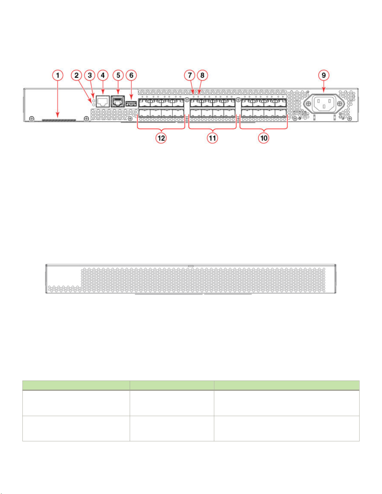
FIGURE 1 Port-side view
Device management options
1. Switch ID pull-out tab
2. System status LED
3. System power LED
4. System RS232 console port (RJ-45)
5. Ethernet port with two Ethernet status LEDs
6. USB port
Nonport-side view
The nonport-side of the device is used solely for air ow.
FIGURE 2 Nonport-side view
Device management options
7. SFP+ FC port 8 (upper) status LED
8. SFP+ FC port 12 (lower) status LED
9. AC power receptacle
10. Trunk port group 2 (SFP+ FC ports 16-23)
11. Trunk port group 1 (SFP+ FC ports 8-15)
12. Trunk port group 0 (SFP+ FC ports 0-7)
You can use the management functions built into the device to monitor the fabric topology, port status, physical status, and other
information to help you analyze switch performance and to accelerate system debugging. The device automatically performs a power-on
self-test (POST) each time it is turned on. A RASlog message is generated for any detected startup errors.
You can manage the device using any of the management options listed in the following table.
TABLE 2 Management options for the device
Management tool Out-of-band support Reference documents
Command line interface (CLI)
Up to two admin sessions and four user
sessions simultaneously.
Brocade EZSwitchSetup
EZSwitchSetup helps to complete the basic
conguration for single-switch setup.
Brocade G610 Hardware Installation Guide
53-1004408-08 13
Ethernet or serial connection Brocade Fabric OS Administration Guide
Brocade Fabric OS Command Reference
Ethernet or serial connection EZSwitchSetup Software Installation Guide
EZSwitchSetup Administrator's Guide

Device management options
TABLE 2 Management options for the device (continued)
Management tool Out-of-band support Reference documents
Brocade Web Tools Ethernet or serial connection Brocade Web Tools Administration Guide
Standard SNMP applications Ethernet or serial connection Fabric OS MIB Reference
Management Server Ethernet or serial connection Brocade Fabric OS Administration Guide
Brocade Fabric OS Command Reference
Brocade Network Advisor (BNA)
BNA must be purchased separately.
Ethernet or serial connection Brocade Network Advisor documentation set
14 53-1004408-08
Brocade G610 Hardware Installation Guide
Preparing for the Installation
• Safety precautions.............................................................................................................................................................................................15
• Facility requirements.........................................................................................................................................................................................17
• Quick installation checklist.............................................................................................................................................................................18
• Shipping carton contents................................................................................................................................................................................20
Safety precautions
When using this product, observe all danger, caution, and attention notices in this manual. The safety notices are accompanied by
symbols that represent the severity of the safety condition
Refer to Cautions and Danger Notices at the end of this guide for translations of safety notices for this product.
General precautions
DANGER
The procedures in this manual are for qualied service personnel.
DANGER
Before beginning the installation, see the precautions in “Power precautions.”
CAUTION
Changes or modications made to this device that are not expressly approved by the party responsible for compliance
could void the user's authority to operate the equipment.
CAUTION
Make sure the airow around the front, and back of the device is not restricted.
CAUTION
Never leave tools inside the chassis.
CAUTION
To protect the serial port from damage, keep the cover on the port when not in use.
CAUTION
Do not install the device in an environment where the operating ambient temperature might exceed 40°C (104°F).
CAUTION
The device must be installed only indoors because the Ethernet ports are not TNV-1 compliant and the device, the AC
power adapter, and the cables are not designed for outdoor use.
ESD precautions
DANGER
For safety reasons, the ESD wrist strap should contain a series 1 megaohm resistor.
Brocade G610 Hardware Installation Guide
53-1004408-08 15
Safety precautions
CAUTION
Before plugging a cable into any port, be sure to discharge the voltage stored on the cable by touching the electrical
contacts to ground surface.
CAUTION
Static electricity can damage the chassis and other electronic devices. To avoid damage, keep static-sensitive devices in
their static-protective packages until you are ready to install them.
NOTE
Wear a wrist grounding strap connected to the chassis ground (if the device is plugged in) or to a bench ground.
Power precautions
DANGER
Make sure that the power source circuits are properly grounded, then use the power cord supplied with the device to
connect it to the power source.
DANGER
If the installation requires a dierent power cord than the one supplied with the device, make sure you use a power cord
displaying the mark of the safety agency that denes the regulations for power cords in your country. The mark is your
assurance that the power cord can be used safely with the device.
DANGER
This device might have more than one power cord. To reduce the risk of electric shock, disconnect all power cords before
servicing.
DANGER
Disconnect the power cord from all power sources to completely remove power from the device.
DANGER
To avoid high voltage shock, do not open the device while the power is on.
DANGER
Batteries used for RTC/NVRAM backup are not located in operator-access areas. There is a risk of explosion if a battery
is replace by an incorrect type. Dispose of used components with batteries according to local ordinance and regulations.
CAUTION
Use a separate branch circuit for each power cord, which provides redundancy in case one of the circuits fails.
CAUTION
Ensure that the device does not overload the power circuits, wiring, and over-current protection. To determine the
possibility of overloading the supply circuits, add the ampere (amp) ratings of all devices installed on the same circuit as the
device. Compare this total with the rating limit for the circuit. The maximum ampere ratings are usually printed on the
devices near the input power connectors.
NOTE
Device control processors and management modules may contain batteries for RTC or NVRAM backup. Dispose of
components containing batteries as required by local ordinances and regulations.
16 53-1004408-08
Brocade G610 Hardware Installation Guide
Lifting and weight-related precautions
DANGER
Use safe lifting practices when moving the product.
DANGER
Mount the devices you install in a rack as low as possible. Place the heaviest device at the bottom and progressively place
lighter devices above.
DANGER
Make sure the rack housing the device is adequately secured to prevent it from becoming unstable or falling over.
CAUTION
Do not use the port cover tabs to lift the module. They are not designed to support the weight of the module, which can fall
and be damaged.
Laser precautions
Facility requirements
DANGER
All ber-optic interfaces use Class 1 lasers.
DANGER
Use only optical transceivers that are qualied by Brocade Communications Systems LLC and comply with the FDA
Class 1 radiation performance requirements dened in 21 CFR Subchapter I, and with IEC 60825 and EN60825. Optical
products that do not comply with these standards might emit light that is hazardous to the eyes.
Facility requirements
Before installing the device, be sure the following facilities requirements are met.
TABLE 3 Facility requirements
Type Requirements
Electrical
Thermal
• Adequate supply circuit, line fusing, and wire size, as specied by the electrical rating on the switch nameplate
• Circuit protected by a circuit breaker and grounded in accordance with local electrical codes
Refer to the Technical Specications at the end of this guide for complete power supply specications.
• A minimum airow of 54.5 cubic meters/hour (32.1 cubic ft/min.) available in the immediate vicinity of the switch
NOTE
Although this airow may exceed the airow maximum listed in the device Technical Specications, the
additional airow is recommended to pressurize the inlet (cool isle) side of rack installations relative to
the exhaust side to minimize recirculation of hot air back to the inlet side.
• Ambient air temperature not exceeding 40°C (104°F) while the switch is operating
Rack (when rackmounted)
Brocade G610 Hardware Installation Guide
53-1004408-08 17
• One rack unit (1U) in a 48.3 cm (19-inch) rack
• All equipment in the rack grounded through a reliable branch circuit connection
• Additional weight of switch not to exceed the rack’s weight limits
• Rack secured to ensure stability in case of unexpected movement

Quick installation checklist
Quick installation checklist
This checklist provides a high-level overview of the basic installation process from the planning stage to the point where the device
comes online and is ready to be deployed. Completing all the tasks in the suggested order ensures successful installation. Brocade
recommends that you print this checklist and take it to the installation site.
Pre-installation tasks
Review all installation requirements ahead of time as part of your site preparation. Careful planning and site preparation ensures seamless
installation, especially when installing multiple devices.
TABLE 4 Installation prerequisites
Task Task details or additional information Completed
Unpack the device. Take an inventory of the hardware components included in your shipment. Refer to
Shipping carton contents on page 20.
Gather necessary components and
required tools.
Review the safety precautions. Refer to Safety precautions on page 15. For translation of these messages, refer to
Plan the installation. Decide whether you want to install the unit on a at surface or in a rack. For rack
Review and verify installation requirements. Verify that the following requirements are met. Refer to Facility requirements on page 17.
Gather network conguration parameters.
Review the time and items required information at the beginning of each chapter to
ensure you have gathered all necessary components required for the following installation
tasks:
• Mounting the Device on page 21.
• Installing Transceivers and Cables on page 67.
Cautions and Danger Notices on page 89 at the end of this guide.
installation, obtain the appropriate rack mount kit. Refer to Mounting options on page
21.
• Power requirements
• Environmental requirements
• Clearance for standalone or rack installation
• IP address:
• Subnet mask:
• Default gateway:
• Domain ID:
• Time zone:
Installation and initial conguration
The initial setup includes mounting the device on a at surface or in a rack and completing the conguration tasks necessary to bring the
device online and verify the operation.
TABLE 5 Installation and basic system conguration
Task Task details or additional information Completed
Mount the device. Choose one of the following mounting options:
• Mount the device as a standalone unit. Refer to Standalone installation on page
22.
• Mount the device using the slide rack mount kit . Refer to Installing the 1U and
2U Fixed-Mount Rack Kit for Four-Post Racks (XBR-R000162) on page 27.
18 53-1004408-08
Brocade G610 Hardware Installation Guide

Quick installation checklist
TABLE 5 Installation and basic system conguration (continued)
Task Task details or additional information Completed
• Mount the device using the xed-mount rack kit on four-post racks. Refer to
Installing the 1U and 2U Fixed-Mount Rack Kit for Four-Post Racks (XBRR000162) on page 27.
• Mount the device using the mid-mount kit on two-post racks. Refer to Installing
the 1U, 1.5U, and 2U Mid-Mount Kit for Two-Post Racks (XBR-000165,
XBR-000175, and XBR-R000292) on page 22
• Mount the device using the non-port side xed-mount rack kit (15"-20") on
four-post racks. Refer toInstalling the 1U and 2U Non-Port Side Fixed-Mount
Rack Kit (15"-20") for Four-Post Racks (XNA-000072 and XNA-100072) on
page 51.
Gather all components required for the
initial setup.
Provide power to the device. Refer to Providing power to the device on page 59.
Attach a management station, establish a
serial connection, and change the default
passwords (optional).
Set the IP address, subnet mask, and the
default gateway IP address.
Set the date and time.
Customize the switch name and chassis
name.
Establish an Ethernet connection. By establishing an Ethernet connection, you can complete the device conguration using
Optional: Congure the DNS service. Use the dnscong command to create DNS server entries. Refer to the Brocade Fabric
Optional: Customize the domain ID. Use the congure command to change the domain ID (default ID is 1). Refer to Setting
Verify that the device operates correctly.
Back up the conguration. Use the interactive congupload command to back up the conguration. Refer to
Optional: Power o the devices. Enter the shutdown command and wait for the device to power down, and then unplug
Refer to Items required on page 59.
Refer to Establishing a rst-time serial connection on page 59. After completing this
task, log in to the serial port to congure the device.
Use the ipaddrset command to congure a static device IP address, subnet mask, and
gateway IP address, or you can use a DHCP server to obtain the information dynamically.
Refer to Conguring the IP address on page 60.
• Use the date command to display and set the date and time.
• Use the tstimezone command to display and set the time zone.
• Use the tsclockserver command to synchronize the time with an external NTP
server.
Refer to Setting the date and time on page 61 for more information.
• Use the switchname command to change the default switch name.
• Use the chassisname command to change the default chassis name.
Refer to Customizing the chassis name and switch name on page 63 for more
information.
a serial session, Telnet, or management application, such as Brocade Network Advisor.
Refer to Establishing an Ethernet connection on page 63.
OS Administration Guide.
the domain ID on page 64 for more information.
• Check the LEDs to verify operation of functional parts. Refer to Verifying
correct operation on page 64.
• The following commands can be useful to establish an operational baseline for
the device. Refer to the Brocade Fabric OS Command Reference for more
information on these commands.
– chassisshow
– psshow
– fanshow
– sfpshow
– tempshow
– historyshow
– errdump
Backing up the conguration on page 65 for more information.
the power cord. Refer to Powering down the device on page 66 for more information.
Brocade G610 Hardware Installation Guide
53-1004408-08 19

Shipping carton contents
Shipping carton contents
When unpacking the device, verify that the contents of the shipping carton is complete. Save the shipping carton and packaging in the
event you need to return the shipment.
• The Brocade G610 device
• An accessory kit containing the following items:
– A serial cable
– One 6-ft. power cord
– Power cord retainer clip
– China-RoHS Hazardous/Toxic Substance statement
– Network Advisor web pointer card.
– EZSwitch web pointer card
– Brocade documentation web pointer card
20 53-1004408-08
Brocade G610 Hardware Installation Guide

Mounting the Device
• Mounting options...............................................................................................................................................................................................21
• Precautions specic to mounting................................................................................................................................................................21
• Standalone installation ....................................................................................................................................................................................22
• Installing the 1U, 1.5U, and 2U Mid-Mount Kit for Two-Post Racks (XBR-000165, XBR-000175,
and XBR-R000292)....................................................................................................................................................................................... 22
• Installing the 1U and 2U Fixed-Mount Rack Kit for Four-Post Racks (XBR-R000162)...................................................27
• Slide Rack Mount Kit (XBR-R000070)...................................................................................................................................................34
• Installing the 1U and 2U Non-Port Side Fixed-Mount Rack Kit (15"-20") for Four-Post Racks
(XNA-000072 and XNA-100072)..........................................................................................................................................................51
Mounting options
You can install the device in several ways:
• As a standalone unit on a at surface, for example, a table top. No other equipment is required for desktop installation.
• In an EIA rack using the 1U Slide Rack Mount Kit (XBR-R000070). Round-hole and square-hole rack posts are supported.
The optional slide-rail rack mount kit can be ordered from your switch retailer.
• In an EIA rack using the 1U Fixed-Mount Rack Kit for Four-Post Racks (XBR-R000162). The optional xed-mount rack kit can
be ordered from your switch retailer.
• In an EIA rack using the 1U Mid-Mount Kit for Two-Post Racks (XBR-000165). The optional mid-mount rack kit can be
ordered from your switch retailer.
• In an EIA rack using the 1U Non-Port Side Fixed-Mount Rack Kit (15"-20") for Four-Post Racks (XNA-000072). The optional
nonport-side xed-mount rack kit can be ordered from your switch retailer.
NOTE
Review the Safety Precautions before mounting the device.
Precautions specic to mounting
The following precautions specically apply to mounting the device.
DANGER
Use safe lifting practices when moving the product.
DANGER
Mount the devices you install in a rack as low as possible. Place the heaviest device at the bottom and progressively place
lighter devices above.
CAUTION
Make sure the airow around the front, and back of the device is not restricted.
CAUTION
Never leave tools inside the chassis.
Brocade G610 Hardware Installation Guide
53-1004408-08 21

Standalone installation
CAUTION
Do not use the port cover tabs to lift the module. They are not designed to support the weight of the module, which can fall
and be damaged.
Standalone installation
Complete the following steps to install the device as a standalone unit on a table.
1. Unpack the device and verify the items listed under the Shipping carton contents on page 20 are present and undamaged.
2. Place the device on a sturdy at surface.
3. Provide power to the device as described in Providing power to the device on page 59.
NOTE
Do not connect the device to the network until the IP address is set correctly. For instructions on how to set the IP
address, refer to Conguring the IP address on page 60.
Installing the 1U, 1.5U, and 2U Mid-Mount Kit for Two-Post Racks (XBR-000165, XBR-000175, and XBR-R000292)
Use the following instructions to install a xed-port device in a mid-mount conguration in a two-post rack using the 1U, 1.5U, and 2U
Mid-Mount Kit for Two-Post Racks (XBR-000165, XBR-000175, and XBR-R000292).
Observe the following when mounting this device:
• Two people are required to install the device in a rack. One person holds the device, while the other secures the device to the
rack.
• Hardware devices illustrated in these procedures are only for reference and may not depict the device you are installing into the
rack.
Time and items required
Allow 15 to 30 minutes to complete the installation procedure.
The following items are required to install a device using the 1U, 1.5U, or 2U Mid-Mount Kit for Two-Post Racks (XBR-000165,
XBR-000175, and XBR-R000292).
• #2 Phillips torque screwdriver
• 1/4 inch slotted-blade torque screwdriver
NOTE
You may need two people to install the device, one to support the device, while the other secures it into the rack.
CAUTION
Use the screws specied in the procedure. Using longer screws can damage the device.
22 53-1004408-08
Brocade G610 Hardware Installation Guide
Installing the 1U, 1.5U, and 2U Mid-Mount Kit for Two-Post Racks (XBR-000165, XBR-000175, and XBR-R000292)
Parts list
The following parts are provided with the 1U, 1.5U, or 2U Mid-Mount Rack Kit for Two-Post Racks (XBR-000165, XBR-000175, and
XBR-R000292).
NOTE
Depending on the device type, not all parts may be used in an installation.
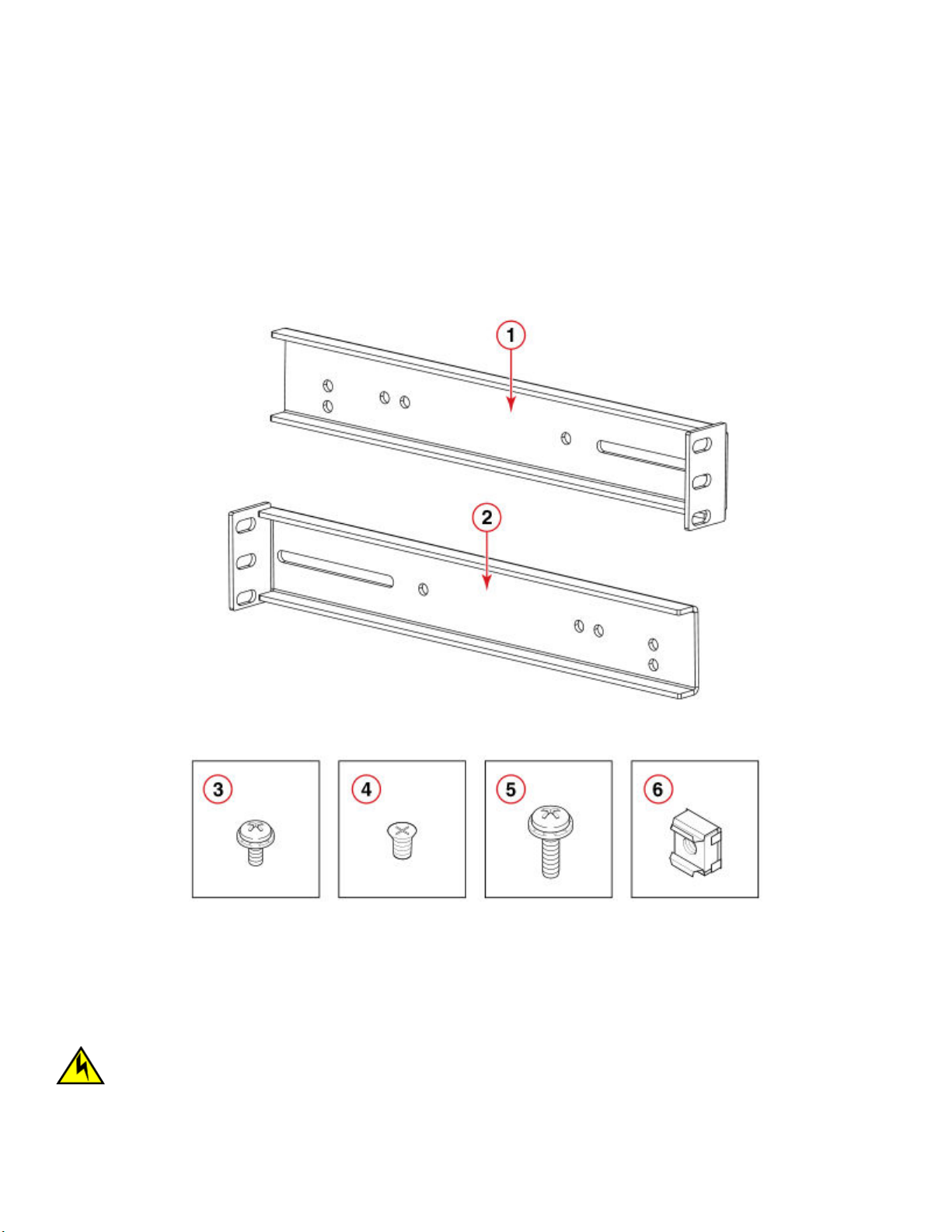
FIGURE 3 Rack kit parts
1. Bracket, front right and back left
2. Bracket, front left and back right
3. Screw, 8-32 x 5/16-in., panhead Phillips (12)
4. Screw, 6-32 x 1/4-in., athead Phillips (8)
5. Screw, 10-32 x 5/8-in., panhead Phillips (8)
6. Retainer nut, 10-32 (8)
Attaching the front brackets to the device
CAUTION
The device must be turned o and disconnected from the fabric during this procedure.
Brocade G610 Hardware Installation Guide
53-1004408-08 23
Installing the 1U, 1.5U, and 2U Mid-Mount Kit for Two-Post Racks (XBR-000165, XBR-000175, and XBR-R000292)
Complete the following steps to attach the front brackets to the device.
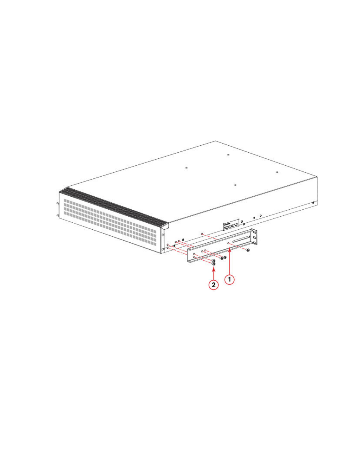
1. Position the right front bracket with the at side against the right side of the device as shown in the following gure.
2. Insert two 8-32 x 5/16-in. screws into one of the pairs of vertically aligned holes in the bracket and then into the vertical pair of
holes on the side of the device. To install the device in a recessed position in the rack, use the bracket holes that are set back
from the end of the bracket.
3. Insert 8-32 x 5/16-in. screws through the rest of the holes in the bracket and into the corresponding holes in the device.
4. Repeat step 1 through step 3 to attach the left front bracket to the left side of the device.
5. Tighten all of the 8-32 x 5/16-in. screws to a torque of 15 in-lbs (17 cm-kgs).
FIGURE 4 Attaching the front brackets
1. Bracket, front right 2. Screw, 8-32 x 5/16-in., panhead Phillips
NOTE
Install the device with the airow aligned with any other devices in the rack. Some devices have airow running from
port side to fan side and others have the opposite arrangement. Make sure that the airow for all devices moves in the
same direction to maximize cooling. Refer to the Hardware Installation Guide for your product for specic
requirements.
Attaching the device to a rack
Complete the following steps to install the device in the rack.
1. Position the device in the rack as shown in the following gure, providing temporary support under the device until the rail kit is
secured to the rack.
2. Attach the right front bracket to the right rack rail using three 10-32 x 5/8-in. screws and three 10-32 retainer nuts.
24 53-1004408-08
Brocade G610 Hardware Installation Guide
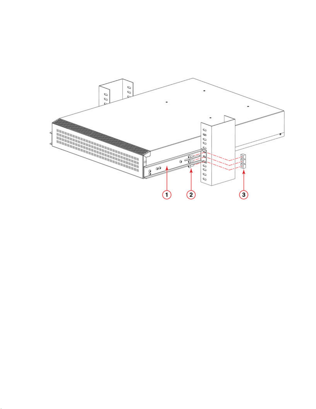
Installing the 1U, 1.5U, and 2U Mid-Mount Kit for Two-Post Racks (XBR-000165, XBR-000175, and XBR-R000292)
3. Attach the left front bracket to the left rack rail using three 10-32 x 5/8-in. screws and three 10-32 retainer nuts.
4. Tighten all the 10-32 x 5/8-in. screws to a torque of 25 in-lbs (29 cm-kgs)
FIGURE 5 Attaching the device to a rack
1. Bracket, front right
2. Screw, 10-32 x 5/8-in., panhead Phillips
3. Retainer nut, 10-32
Attaching the rear brackets to the rack
NOTE
Do not use the rear brackets for the Brocade 6505, 6510, or 6520 switches.
Complete the following steps to attach the rear brackets to the rack.
1. Position the right rear bracket in the right rear of the device as shown in the following gure.
2. Attach the brackets using three 10-32 x 5/8-in. screws and 10-32 retainer nuts.
3. Repeat step 1 and step 2 to attach the left rear bracket.
Brocade G610 Hardware Installation Guide
53-1004408-08 25
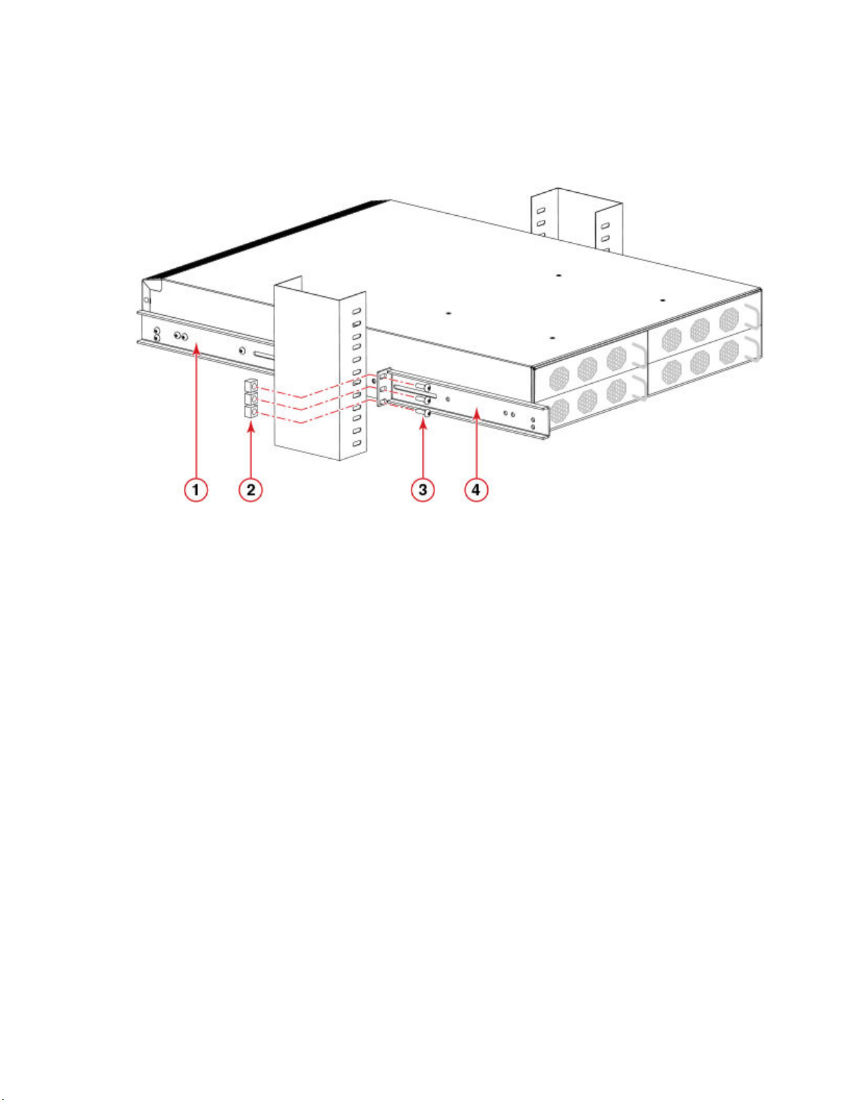
Installing the 1U, 1.5U, and 2U Mid-Mount Kit for Two-Post Racks (XBR-000165, XBR-000175, and XBR-R000292)
4. Adjust the brackets to the rack depth and tighten the screws to a torque of 25 in-lbs (29 cm-kgs).
FIGURE 6 Attaching the rear brackets to a rack
1. Bracket, front right
2. Retainer nut, 10-32
3. Screw, 10-32 x 5/8-in., athead Phillips
4. Bracket, rear right
Attaching the rear brackets to the device
Complete the following steps to attach the rear brackets to the device.
1. Align the right rear bracket to the right rear of the device and use two 8-32 x 5/16-in. screws to attach the bracket to the device
as shown in the following gure.
2. Align the left rear bracket to the left rear of the device and use two 8-32 x 5/16-in. screws to attach the bracket to the device as
shown in the following gure.
26 53-1004408-08
Brocade G610 Hardware Installation Guide
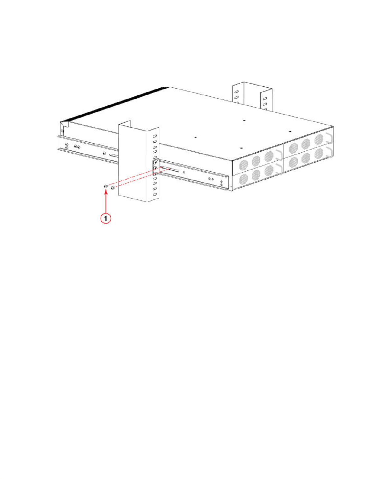
3. Tighten all the screws to a torque of 9 in-lbs (10 cm-kgs).
FIGURE 7 Attaching the rear brackets to the device
Installing the 1U and 2U Fixed-Mount Rack Kit for Four-Post Racks (XBR-R000162)
1. Screw, 8-32 x 5/16-in., panhead Phillips
Installing the 1U and 2U Fixed-Mount Rack Kit for
Four-Post Racks (XBR-R000162)
Use the following instructions to install a xed-port device in a xed-mount conguration using the 1U and 2U Fixed-Mount Rack Kit for
Four-Post Racks (XBR-R000162).
Observe the following when mounting this device:
• Two people are required to install the device in a rack. One person holds the device, while the other secures the device to the
rack.
• Use Electronic Industries Association (EIA) standard racks.
• Hardware devices illustrated in these procedures are only for reference and may not depict the device you are installing into the
rack.
Time and items required
Allow 15 to 30 minutes to complete the installation procedure.
The following items are required to install a device using the 1U and 2U Fixed-Mount Rack Kit for Four-Post Racks (XBR-R000162).
• #2 Phillips torque screwdriver
• 1/4-inch slotted-blade torque screwdriver
Brocade G610 Hardware Installation Guide
53-1004408-08 27

Installing the 1U and 2U Fixed-Mount Rack Kit for Four-Post Racks (XBR-R000162)
NOTE
You may need two people to install the device, one to support the device, while the other secures it into the rack.
CAUTION
Use the screws specied in the procedure. Using longer screws can damage the device.
Parts list
The following parts are provided with the 1U and 2U Fixed-Mount Rack Kit for Four-Post Racks (XBR-R000162).
28 53-1004408-08
Brocade G610 Hardware Installation Guide
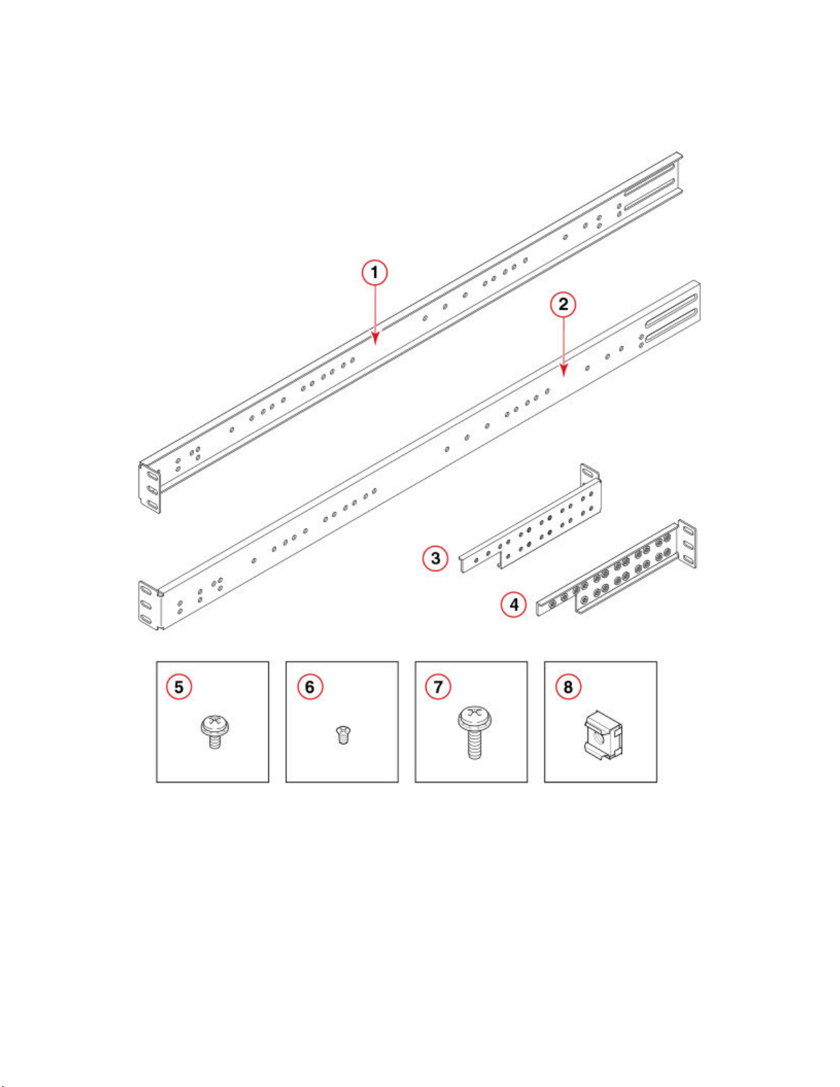
FIGURE 8 Rack kit parts
Installing the 1U and 2U Fixed-Mount Rack Kit for Four-Post Racks (XBR-R000162)
1. Bracket, front right
2. Bracket, front left
3. Bracket, rear left
4. Bracket, rear right
5. Screw, 8-32 x 5/16-in., panhead Phillips (12)
6. Screw, 6-32 x 1/4-in., athead Phillips (8)
7. Screw, 10-32 x 5/8-in., panhead Phillips (8)
8. Retainer nut, 10-32 (8)
NOTE
Not all parts may be used with certain installations depending on the device type.
NOTE
Although this document describes how to install single-height (1U) and double-height (2U) devices, the illustrations show a
single-height device as a typical installation.
Brocade G610 Hardware Installation Guide
53-1004408-08 29
Loading...