

Page 1
“An American Tradition Since 1954!”
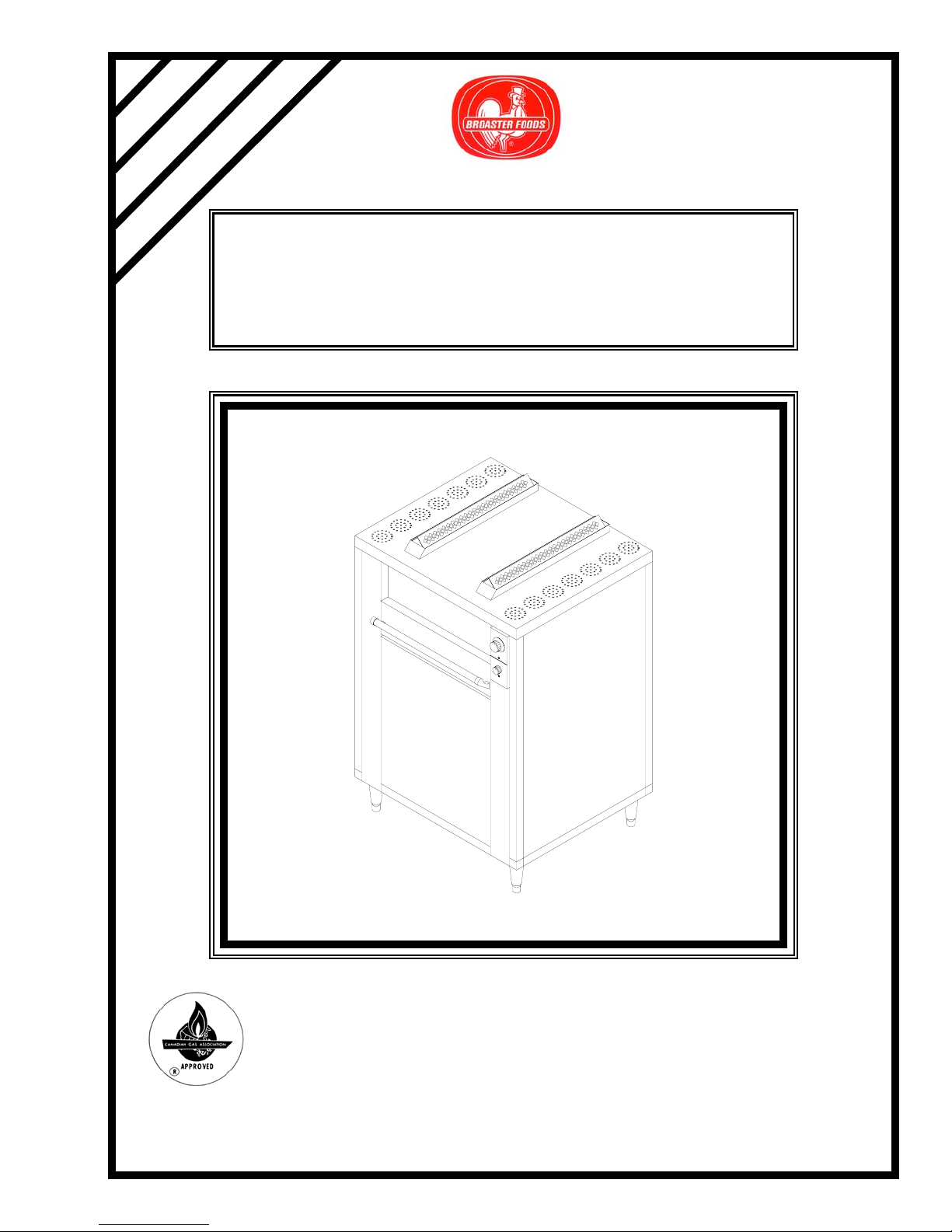
MODEL 2000 BROILER
INSTALLATION AND OPERATION
MANUAL
Effective: S2KA790010
Be sure ALL installers read, understand, and have access to this manual at all times.
2855 Cranston Road, Beloit, WI 53511-3991
Design Certified by: AGA, CGA, and NSF
Printed in USA
The Broaster Company
608/365-0193 www.broaster.com
13799 5/97 Rev 3/06
Copyright 1997 The Broaster Company
Page 2

Page 3
FOR YOUR SAFETY
Do not use or store gasoline or other flammable vapors
or liquids in the vicinity of this or any other appliance.
WARNING: Improper installation, adjustments, alteration, service or maintenance can
cause property damage, injury or death. Read the installation, operating and maintenance instructions thoroughly before installing or servicing this equipment.
For the sake of safety and clarity, the following words used in this manual are defined as follows:
DANGER: Indicates an imminently hazardous situation which, if not avoided, could result
in serious injury or death.
WARNING: Indicates a potentially hazardous situation which, if not avoided, could result
in serious injury or death.
CAUTION: Indicates a potentially hazardous situation which, if not avoided, could result in
minor injury, property damage or both.
All adjustments and repairs shall be made
by an authorized Broaster Company representative.
If there is a power failure, turn POWER on
switch OFF. DO NOT attempt to operate
unit during a power failure.
WARNING: Failure to read and
understand this manual completely
could result in serious injury or death. Be
sure ALL operators read, understand and
have access to this manual at all times.
WARNING: Rags or papers containing
cooking oil can catch fire if exposed to
heat. Laundering will not remove the oil. Dispose of all oil-soiled papers and rags in a trash
container that is in a ventilated area away from
all cooking equipment or other heat sources
such as direct sunlight.
Manual #13799 5/97 Rev 3/06
Page 4

Page 5

TABLE OF CONTENTS
1 - LIMITED WARRANTY...................................................................................................1 - 1
2 - OWNER’S RESPONSIBILITY .......................................................................................2 - 1
3 - INSTALLATION.............................................................................................................3 - 1
GENERAL ...................................................................................................................3 - 1
LOCATION.................................................................................................................. 3 - 1
CLEARANCE............................................................................................................... 3 - 1
LEVELING...................................................................................................................3 - 2
VENTILATION.............................................................................................................3 - 2
General Requirements........................................................................................3 - 2
Hood Dimensions In Inches ................................................................................3 - 3
GAS SPECIFICATIONS..............................................................................................3 - 4
Connecting..........................................................................................................3 - 4
ELECTRICAL SPECIFICATIONS ............................................................................... 3 - 4
Connecting..........................................................................................................3 - 4
Wiring Diagram....................................................................................................3 - 5
INSTALLING REMOVABLE PARTS...........................................................................3 - 6
Grease Baffles..................................................................................................... 3 - 6
Drip Pan .............................................................................................................. 3 - 6
Drip Tray.............................................................................................................. 3 - 7
Door Panel .......................................................................................................... 3 - 7
Stack Guards.......................................................................................................3 - 8
Meat Rack...........................................................................................................3 - 8
4 - OPERATOR’S INSTRUCTIONS....................................................................................4 - 1
PRE-HEATING............................................................................................................4 - 1
BROILING ...................................................................................................................4 - 1
BROILING TIMES ....................................................................................................... 4 - 2
Filet Steaks..........................................................................................................4 - 2
Strip Steaks.........................................................................................................4 - 2
Ribeye Steaks .....................................................................................................4 - 2
Baby Back Ribs...................................................................................................4 - 2
Boneless Chicken Breasts .................................................................................. 4 - 2
8 Piece Cut Chicken (Bone-In)............................................................................4 - 2
Cod Fillets ...........................................................................................................4 - 3
Potatoes.............................................................................................................. 4 - 3
Manual #13799 5/97
Page 6

5 - CLEANING AND MAINTENANCE ................................................................................5 - 1
SHUTDOWN ............................................................................................................... 5 - 1
PARTS REMOVAL......................................................................................................5 - 1
Door Panel .......................................................................................................... 5 - 1
Drip Tray.............................................................................................................. 5 - 2
Drip Pan .............................................................................................................. 5 - 2
Grease Baffles..................................................................................................... 5 - 3
Meat Rack...........................................................................................................5 - 3
CLEANING.................................................................................................................. 5 - 4
PREVENTIVE MAINTENANCE................................................................................... 5 - 5
6 - TROUBLESHOOTING...................................................................................................6 - 1
Manual #13799 5/97
Page 7

1 - LIMITED WARRANTY
Subject to the terms and conditions of this warranty, The Broaster Company (Company) warrants that all equipment and parts manufactured or sold by the Company and purchased new
from an authorized Company distributor are free from defects in material and workmanship for a
period of one year from the date of installation, if installation is made by a qualified installer
under supervision by an authorized distributor in accordance with applicable laws and regulations. Warranty coverage is extended to the original purchaser only and is void if the equipment
is resold. If an authorized Company distributor is notified of a warranty claim during the warranty period, the Company will at its option replace, recondition or repair at its factory any part
or parts of the equipment which the Company judges defective, provided the equipment has
been subjected to normal usage, properly installed, operated and serviced in accordance with
Company operating instructions, and there is no evidence of accident, alteration or abuse of the
equipment or the use of unauthorized repair methods. All parts replaced under this warranty
carry only the unexpired term of the warranty.
Service under this warranty shall be furnished only by an authorized Company distributor. The
Company does not send service representatives to furnish warranty service. Your authorized
Company distributor should be contacted for warranty service.
This warranty covers parts only and does not cover labor charges, transportation charges or
other expenses in the connection with warranty service, which are the obligation of the owner
unless otherwise specified in the original sales contract between the purchaser and the authorized Company distributor from which the equipment is purchased. Please refer to that contract
for coverage as to those charges.
The foregoing warranty is made in lieu of all other warranties, express or implied, and
the Company specifically disclaims any implied warranties of merchantability or fitness
for a particular purpose. The Company’s full obligation under this warranty, and the pur-
chaser’s sole remedy shall be limited to replacement, reconditioning or repair as specified
above.
IN NO EVENT SHALL THE COMPANY BE LIABLE TO THE ORIGINAL OWNER OR ANY
OTHER PERSON FOR ANY INCIDENTAL, CONSEQUENTIAL OR SPECIAL DAMAGES
RESULTING FROM THE USE OR INABILITY TO USE THE EQUIPMENT COVERED
HEREBY, WHETHER ARISING FROM BREACH OF WARRANTY, STRICT LIABILITY OR
OTHERWISE.
The Company reserves the right to change or improve its products in any way without obligation
to alter products previously manufactured.
Used Company equipment or Company equipment not purchased from an authorized distributor carries no warranty express or implied.
Manual #13799 5/97 1 - 1
Page 8

Page 9

2 - OWNER’S RESPONSIBLITY
It is the owners responsibility to:
• Insure the unit is properly maintained.
• Insure all warning signs are in place and
legible.
• Allow only properly trained personnel to
operate, clean, and maintain your unit.
• Retain this manual for future reference.
• Make this manual easily accessible to all
personnel.
• When you sell, trade or give away your
unit, you must make sure all warning
signs are intact and legible and the operators manual is included with the unit.
• Be sure main electric power supply is
disconnected before cleaning and servicing.
If you need replacement warning signs or
manuals, contact an authorized Broaster
Company representative or The Broaster
Company at 608/365-0193.
The Customer Service Department at The
Broaster Company should be contacted at
the time of sale or disposal of your unit so
records may be updated.
• Be sure main gas supply is OFF before
cleaning or servicing.
Manual #13799 5/97 2 - 1
Page 10

Page 11

3 - INSTALLATION
GENERAL
• Installation must conform to local codes
or in the absence of local codes, with the
National Fuel Gas Code, ANSI Z223.1.
• Canada: Installation shall be made in
accordance with CAN 1-B1491.1 & 2
“Installation Codes for Gas Burning
Appliances and Equipment” or local
codes.
• A remote circuit breaker or fuse, installed
in main power supply, should be located
in a path of exit and clearly identified.
• A gas shut-off valve, installed in the gas
supply line, should be located in a path
of exit and clearly identified.
• DO NOT obstruct flow of combustion
and ventilation air.
• The unit and its individual shut-off valve
must be disconnected from the gas supply piping system during any pressure
testing of that system at test pressures in
excess of 1/2 psig.
LOCATION
For convenience and speed, location of the
unit should be given careful consideration.
If possible, locate the unit so the flow of
cooked product is in a straight line from storage, in and out of the unit and to the customer.
• Unit must be restrained to prevent tipping and strain on electrical and gas
connections. This can be done by
installing unit in a battery of appliances,
in an alcove , or with adequate ties.
• DO NOT install unit where traffic areas
are on either side or in back of the unit.
CLEARANCE
• DO NOT obstruct open area around bottom of unit at the front, back, and sides
which would restrict combustion air to
the burner’s. Provisions must be provided for adequate air supply.
• Required Clearances:
• The unit must be isolated from the gas
supply piping system by closing its individual manual shut-off valve during any
pressure testing of the gas supply piping
system at test pressures equal to or less
than 1/2 psig.
• Keep area around unit clear of all combustible materials.
• Consult your local Broaster Company
representative for gas conversions and
installations exceeding 2000 feet above
sea level.
Manual #13799 5/97 3 - 1 Replace 10/97
From Combustible Surfaces:
Left Side: 1 inch minimum
Right Side: 12 inches minimum
Rear: 6 inches minimum
From Non-Combustible Surfaces:
Left Side: 0 inches
Right Side: 0 inches
Rear: 6 inches minimum
• Recommended Clearances:
Eighteen inch (18”) minimum clearance on sides and back of unit for
servicing.
Page 12

LEVELING
Adjust feet to level entire unit.
VENTILATION
Exhaust hood should comply with ANSI/
NFPA #96 or national, state, and local
codes. All units must be under an adequate
power exhaust hood for ventilation of cooking vapors and products of combustion.
Precautions should be taken in the design of
the exhaust hood to avoid interference with
operation of the unit. Consult a local ventilation company for fire suppression, design,
and installation of a hood.
3. Hood Size: The overhead canopy
type hood should be sized to completely cover the equipment it is
designed to ventilate plus an overhang
of at least six inches (6”) on all sides of
equipment not immediately adjacent to
walls or other construction extending
above the cooking surface. Non-canopy, prefabricated “backshelf” type
hoods should be sized according to the
manufacturers specifications.
4. Exhaust Air Volume (Minimum):
Canopy hood open on all four sides:
1800 cu. ft./minute. Canopy hood
open on three sides or less: 1200 cu.
ft./minute.
WARNING: DO NOT extend the
exhaust flue of any unit. Doing so may
cause a negative back draft causing malfunction and interference with burner operation and improper exhausting of cooking
vapors.
General Requirements:
1. Exhaust hood must conform to applicable national, state, and local codes.
2. It is recommended that requirements of
the National Fire Protection Association (NFPA), Standard No. 96 be followed for the design, installation, and
use of exhaust system components.
This includes hoods, grease removal
devices, exhaust ducts, dampers, air
moving devices, auxiliary equipment,
and fire extinguishing equipment for
the exhaust system and the cooking
equipment used therewith in commercial, industrial, institutional, and similar
cooking applications.
5. Exhaust Air Velocity: All exhaust
ducts should be sized to provide an air
velocity in the ducts of at least 1500 ft./
minute.
Manual #13799 5/97 3 - 2
Page 13
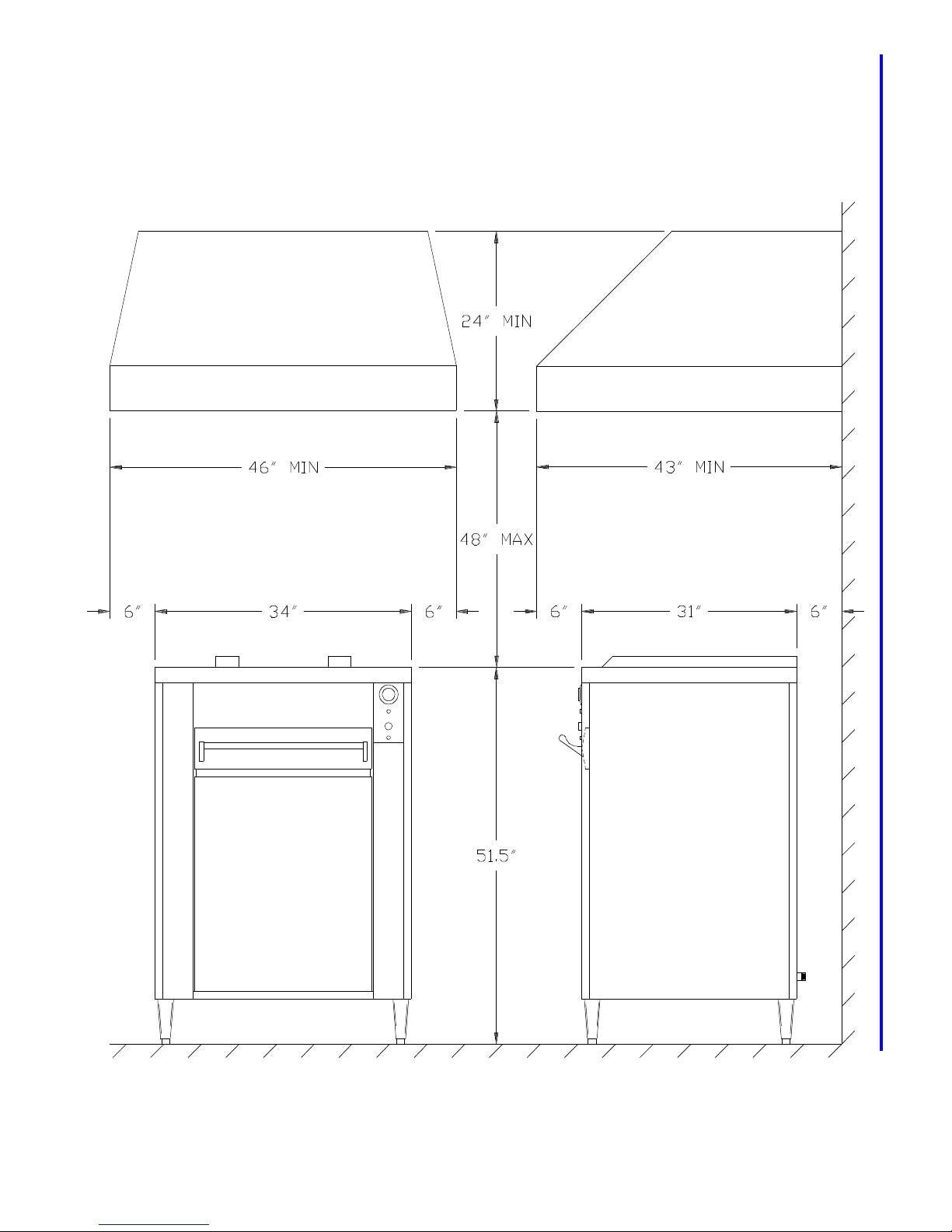
Hood Dimensions In Inches:
Manual #13799 5/97 3 - 3
Page 14
GAS SPECIFICATIONS
ELECTRICAL SPECIFICATIONS
• Consult your local Broaster Company
representative for gas conversions and
installations exceeding 2000 feet above
sea level.
• Gas Pressure and Orifice Size:
Manifold Gas Pressure:
NAT - On HIGH = 4.5” W.C.
LP - On HIGH = 8” W.C.
Burner Orifice Size:
NAT - #49 P/N 06783
LP - #56 P/N 06972
LOW Fire Orifice Size:
NAT - #24 P/N 14144
LP - #31 P/N14145
Connecting:
• A 1/2” pipe is located in the rear for gas
connection. Connect unit to 3/4” gas
supply line using adapter included with
your unit.
• Gas piping should conform to NFPA #54
or national, state, and local codes.
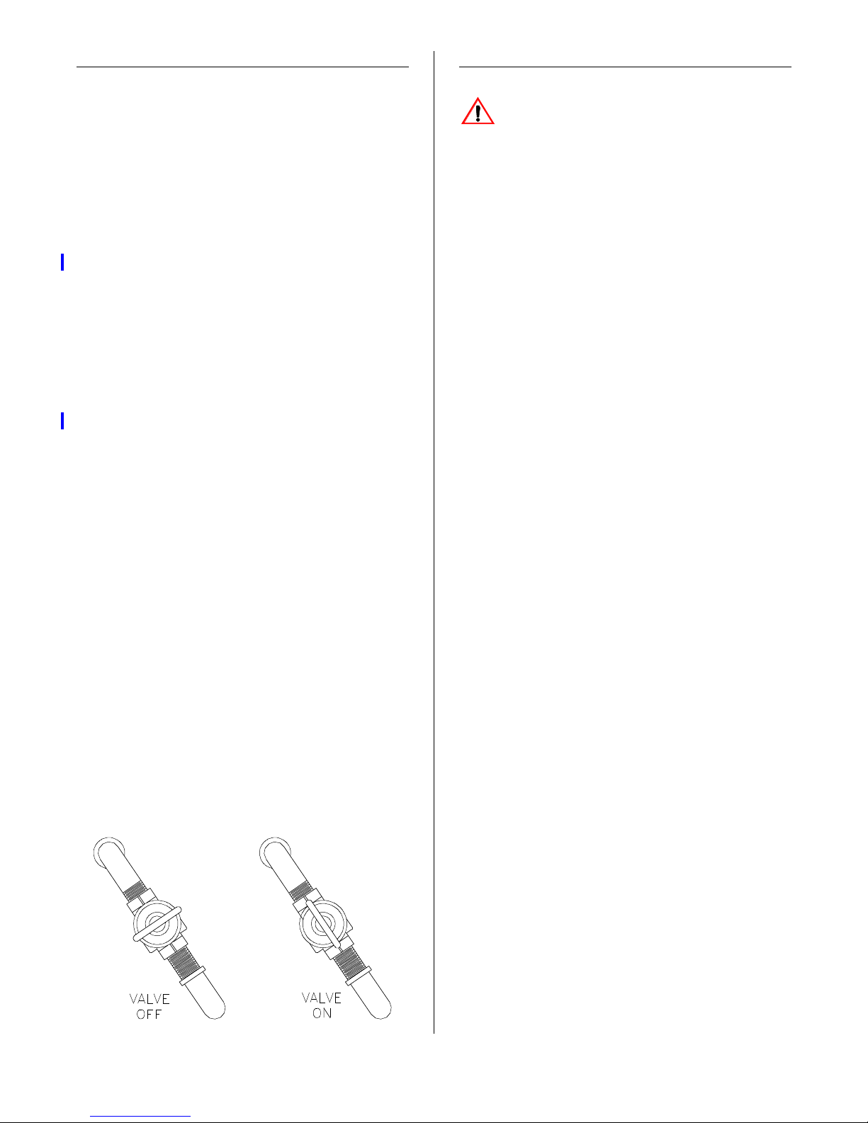
1. Turn POWER ON switch OFF.
2. After unit is installed in its permanent
location, turn gas shut-off valve ON.
Check all connections and pipes with a
soap and water solution. Bubbles indicate a gas leak.
WARNING: Electrical Grounding
Instructions - This unit is equipped
with a three-prong (grounding) plug for your
protection against shock hazard and should
be plugged directly into a properly grounded
three-prong receptacle. DO NOT cut or
remove grounding prong from this plug.
• When installed, the unit must be electri-
cally grounded in accordance with local
codes, or in the absence of local codes,
with the National Electrical Code, ANSI/
NFPA 70.
• Canada: When installed, the unit must
be electrically grounded in accordance
with local codes, or in the absence of
local codes, with the Canadian Electrical
Code, CSA C22.2.
• The model 2000 Broiler is 1 20VAC,
1.25amp, 60Hz, grounded.
• When installing or servicing the unit,
always check the data plate located on
the inside of right hand side panel to
make certain proper parts are used and
the correct service rendered. DO NOT
apply a voltage to this unit other than
that shown on the data plate. If in doubt,
consult your local power company.
Connecting:
1. Turn POWER ON switch OFF.
2. After unit is installed in its permanent
location, plug in main power supply
cord attached to your unit.
Manual #13799 5/97 3 - 4 Replace 8/97
Page 15
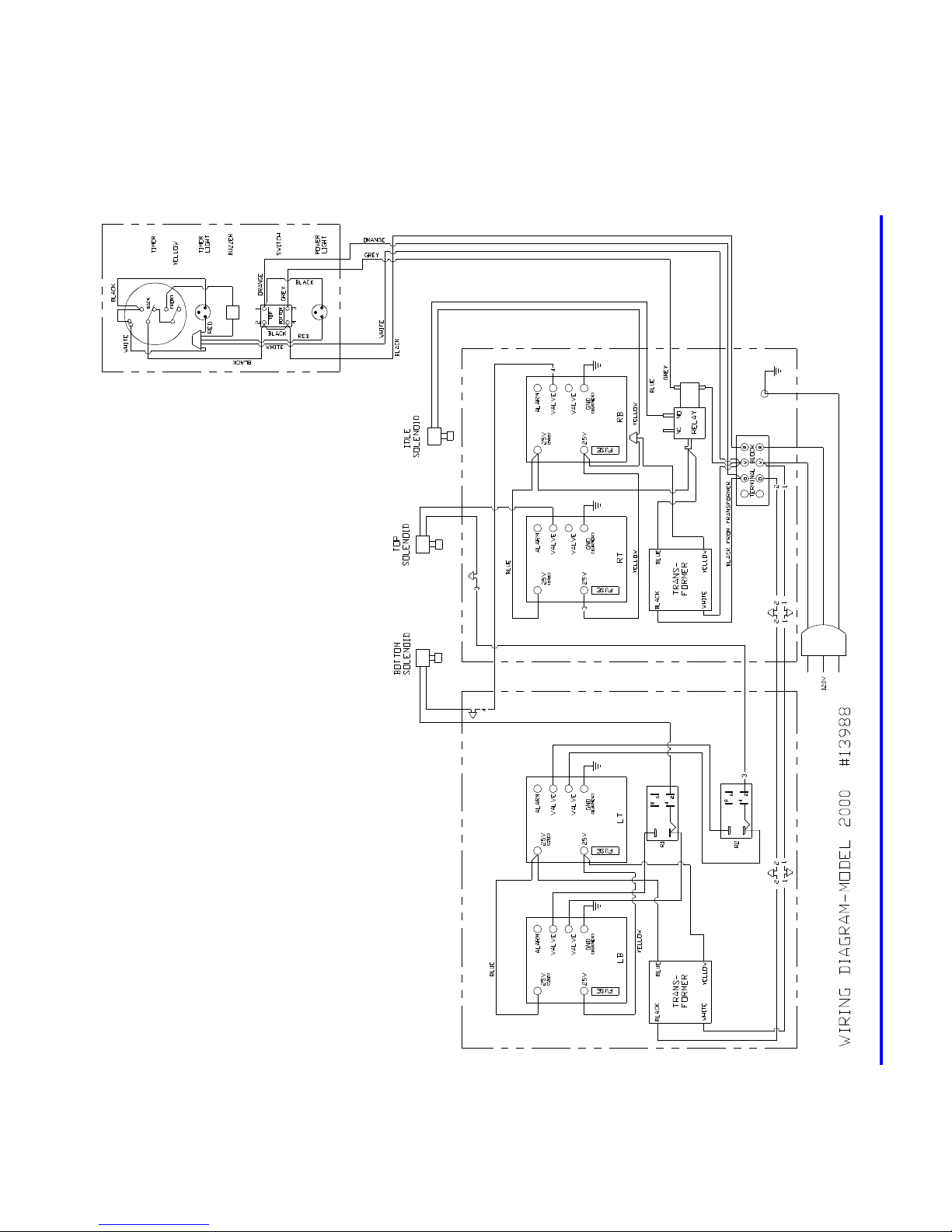
Wiring Diagram:
Located on inside right hand side panel.
Manual #13799 5/97 3 - 5
Page 16
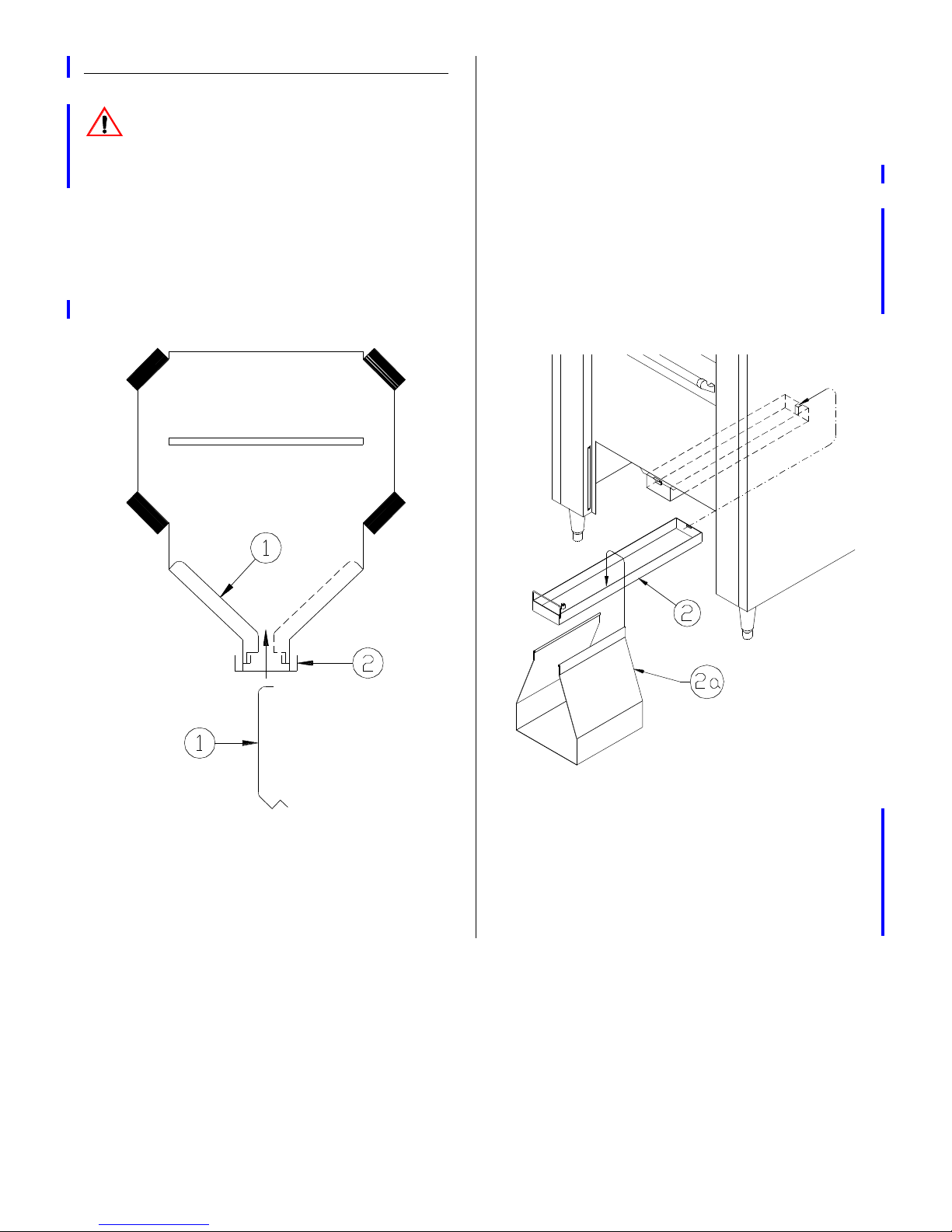
INSTALLING REMOVABLE PARTS
Drip Pan:
WARNING: Operating broiler without
baffles installed and cooking oil in drip
pan could result in fire and possible personal injury.
Grease Baffles:
1. From bottom of unit, install baffles (1)
by raising them above retaining ridge
and dropping into position.
1. Install rear of drip pan (2) then lift up on
the front and install swinging handle
onto front tab.
2. Fill drip pan to overflow level with cooking oil. DO NOT use water. Water
evaporates too quickly. Oil in the pan
creates an air tight seal. An air tight
seal prevents food product flame-up,
smoke, and extended cook times.
Manual #13799 5/97 3 - 6
3. Install condensate pan support (2a)
toward front of drip pan (2).
4. Install half size pan onto condensate
pan support directly beneath overflow
in drip pan.
Page 17
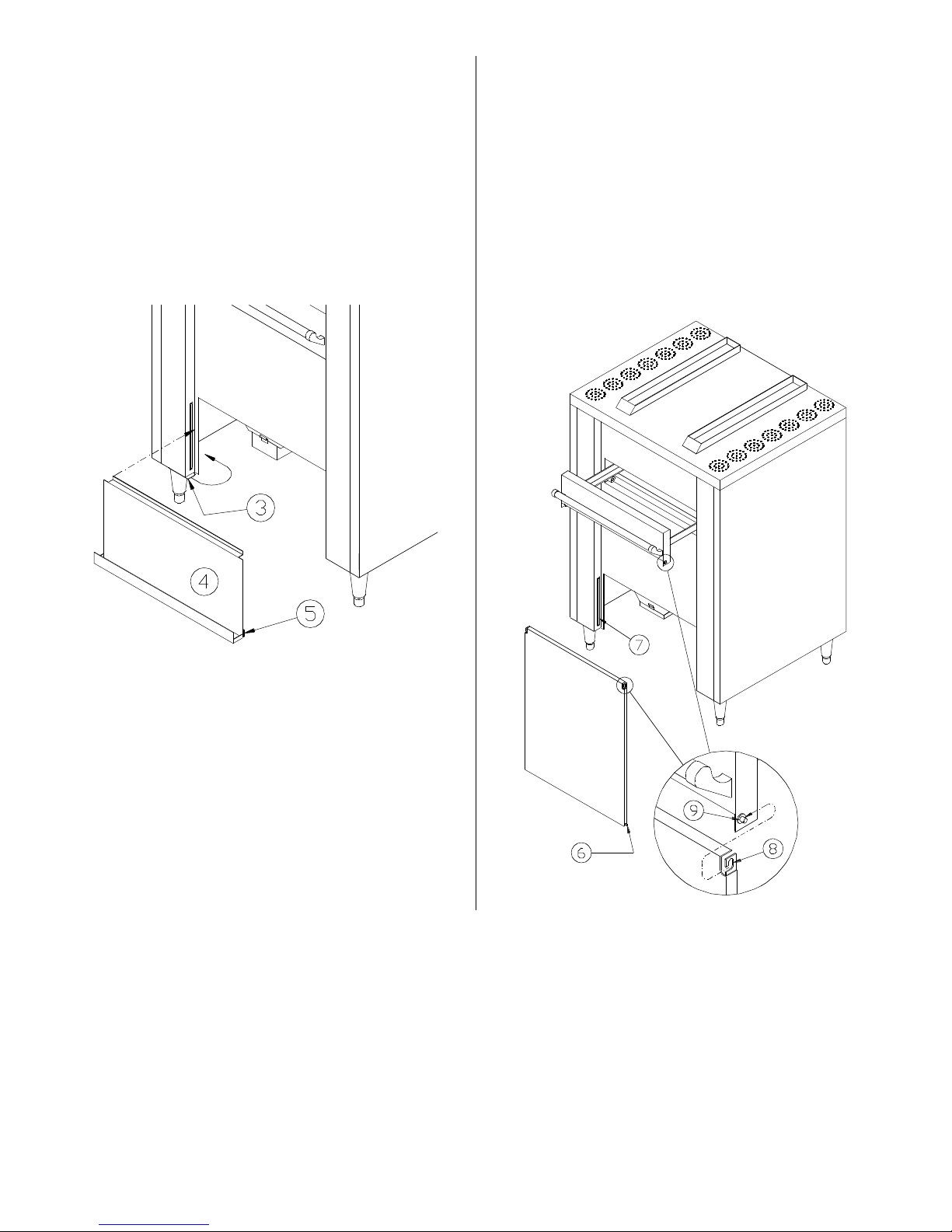
Drip Tray:
Door Panel:
1. Rotate retaining clips (3) back.
2. Install drip tray (4) onto front of unit and
slide up. Be sure edge of front panel
engages clips (5) at the bottom of pan.
3. Rotate retaining clips (3) forward to
secure pan.
1. Pull drawer out approximately 4
inches.
2. Install door at an angle. Install one
lower pin (6) into slide (7) and tilt door
until other pin is installed.
3. Install door hangers (8) onto drawer
pins (9).
Manual #13799 5/97 3 - 7
Page 18
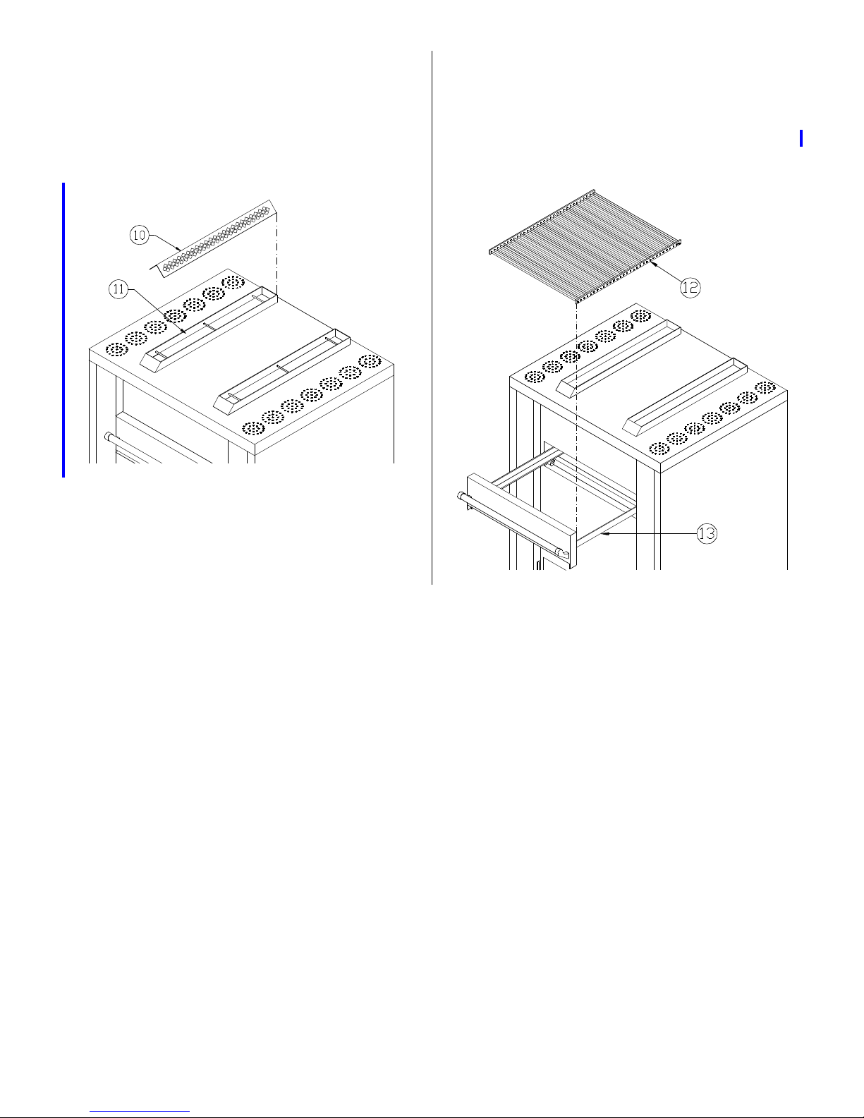
Stack Guards:
Meat Rack:
1. Install stack guards (10) into two large
slots (11) on top of unit. Guards sit on
top of three rods inside of stack.
1. Open broiling drawer.
2. Simply slide rack (12) onto rails (13).
Manual #13799 5/97 3 - 8
Page 19
4 - OPERATOR’S INSTRUCTIONS
PRE-HEATING
WARNING: Be sure all loose parts
are installed and drip pan is filled to
the overflow level with cooking oil. DO NOT
use water. Water evaporates too quickly.
Oil in the pan creates an air tight seal. An
air tight seal prevents food product flameup, smoke, and extended cook times.
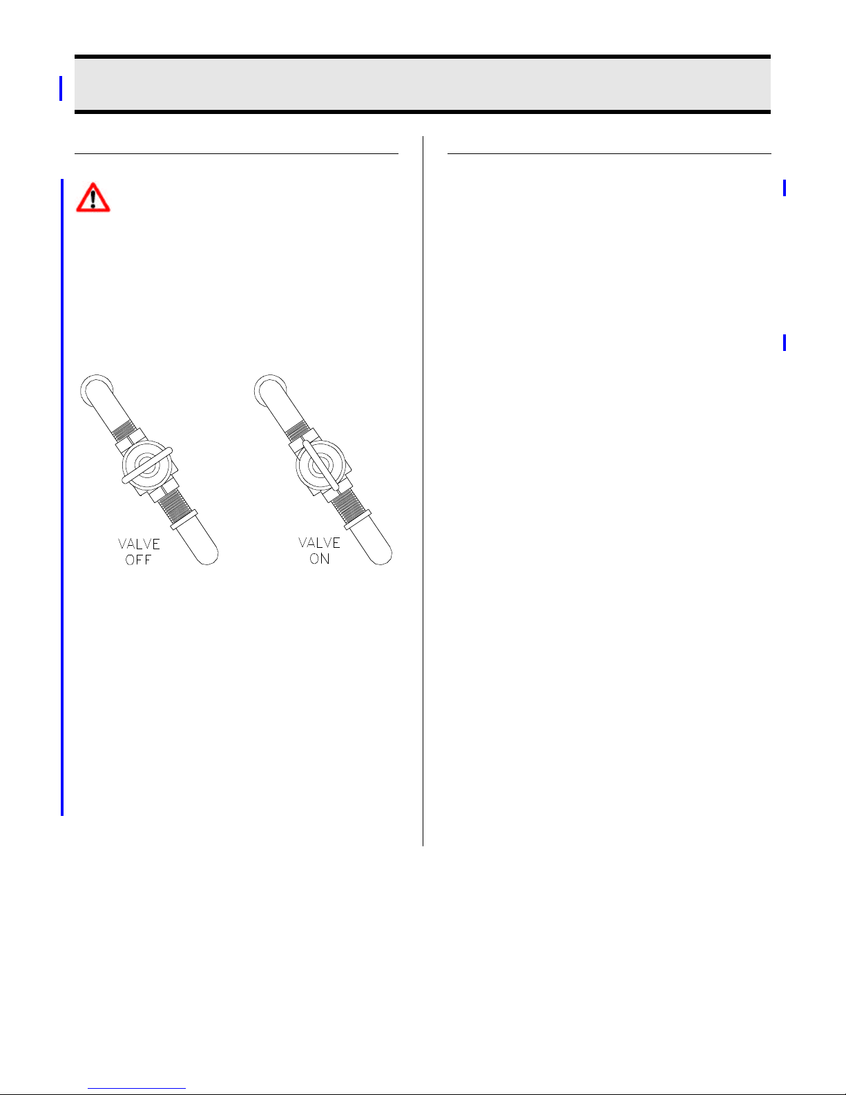
1. Turn gas shut-off valve ON.
BROILING
See BROILING TIMES.
1. Open drawer.
2. With tongs or hot mitt, load food on
broiling rack. Load food in a single
layer and close drawer.
3. Set timer to desired time .
4. When alarm sounds, turn timer OFF.
Open drawer and unload food.
5. Close drawer.
2. To ignite burners, turn POWER ON
switch to HIGH. Open broiler drawer to
be sure all four burners ignite. If not,
turn POWER ON switch OFF. Wait
five minutes before attempting to relight burners.
3. Turn timer to 15 minutes. When alarm
sounds, turn timer to OFF and POWER
ON switch to LOW.
Note: Do not leave unit on HIGH during idle
periods.
Manual #13799 5/97 4 - 1
Page 20

BROILING TIMES
For best results for thicker food products (ie:
chicken parts) or products generally slow
cooked (ie: ribs) cook products fully by other
cooking methods. Reheat to a minimum
internal temperature of 165°F in Model
2000.
Pork Steaks:
Lightly season both sides of steak with
Broaster Foods Prep Seasoning or Barbecue Seasoning and allow to set-up a
minimum of 1 minute. Broil on HIGH.
See following cook times for steaks
cooked to an internal temperature of
160°F.
Ribeye Steaks
Lightly season both sides with Broaster
Foods Prep Seasoning and allow to setup a minimum of 1 minute. Broil on
HIGH. See Following cook times for
steaks cooked to medium (light pink in
center and brown toward exterior) or an
internal temperature of 160°F.
1/2 inch thick (4 oz.) approx. 3 minutes.
3/4 inch thick (6 oz.) approx. 3-1/2 to 4
minutes.
1 inch thick (10 oz.) approx. 4-1/2 to 5
minutes.
Ground Round Steaks:
Lightly season both sides with Broaster
Foods Prep Seasoning and allow to setup a minimum of 1 minute.
Cook to a minimum internal temperature
of 160°F.
3/4” thick
Broil time = approximately 3 1/2 minutes
on HIGH.
1/2 inch thick (8 oz.) approx. 4 to 5 minutes.
1 inch thick (16 oz.) approx. 7 to 8 minutes.
Pork Chops:
Lightly season both sides of chop with
Broaster Food Prep Seasoning and
allow to set up for one minute. Broil on
HIGH. See following cook times for
chops cooked to an internal temperature
of 160°F.
1/2 inch thick (5 TO 6 OZ.) approx. 3
minutes.
1 inch thick (6to 8 oz.) approx.5 to 5-1=2
minutes
Boneless Chicken Breast Fillets:
Lightly season both sides of fillet w ith
Broaster Food s Original Brotisserie S easoning and allow it to set-up for one
minute. See following cook times. See
cook times for fillets cooked to an internal temperature is 170°F.
Product continues to cook after removing from broiler. Allow products to “stand” for approx.
2 minutes after cooking.
Manual #13799 5/97 4 - 2 Replace 1/98
1/2 inch thick (5 oz.) approx.5-1/2 to 6 min-
utes.
Page 21

Potatoes:
Pierce potatoes with a fork and wrap in
foil.
Broil time = approximately 35 - 40 minutes on HIGH.
Fish:
To prevent sticking to rack, fish is best
prepared in a pan designed for steaming. Pan is placed on rack.
Place false bottom in 2 1/2” deep pan
and fill with approximately 1” of water.
Preheat pan for 5 minutes or until water
is steaming.
Lightly season both sides of thawed
block of fish.
Lightly brush false bottom with cooking
oil. Place fish on false bottom.
3/4” thick
Broil time = approximately 5 minutes on
HIGH.
1” thick
Broil time = approximately 6 minutes on
HIGH.
Product continues to cook after removing from broiler. Allow products to “stand” for
approx.2 minutes after cooking.
Manual #13799 5/97 4 - 3 Replace 1/98
Page 22

Page 23
5 - CLEANING AND MAINTENANCE
SHUTDOWN
WARNING: Rags or papers contain-
ing cooking oil can catch fire if
exposed to heat. Laundering will not
remove the oil. Dispose of all oil-soiled
papers and rags in a trash container that is
in a ventilated area away from all cooking
equipment or other heat sources such as
direct sunlight.
1. Turn POWER ON switch OFF.
2. Turn gas shut-off valve OFF.
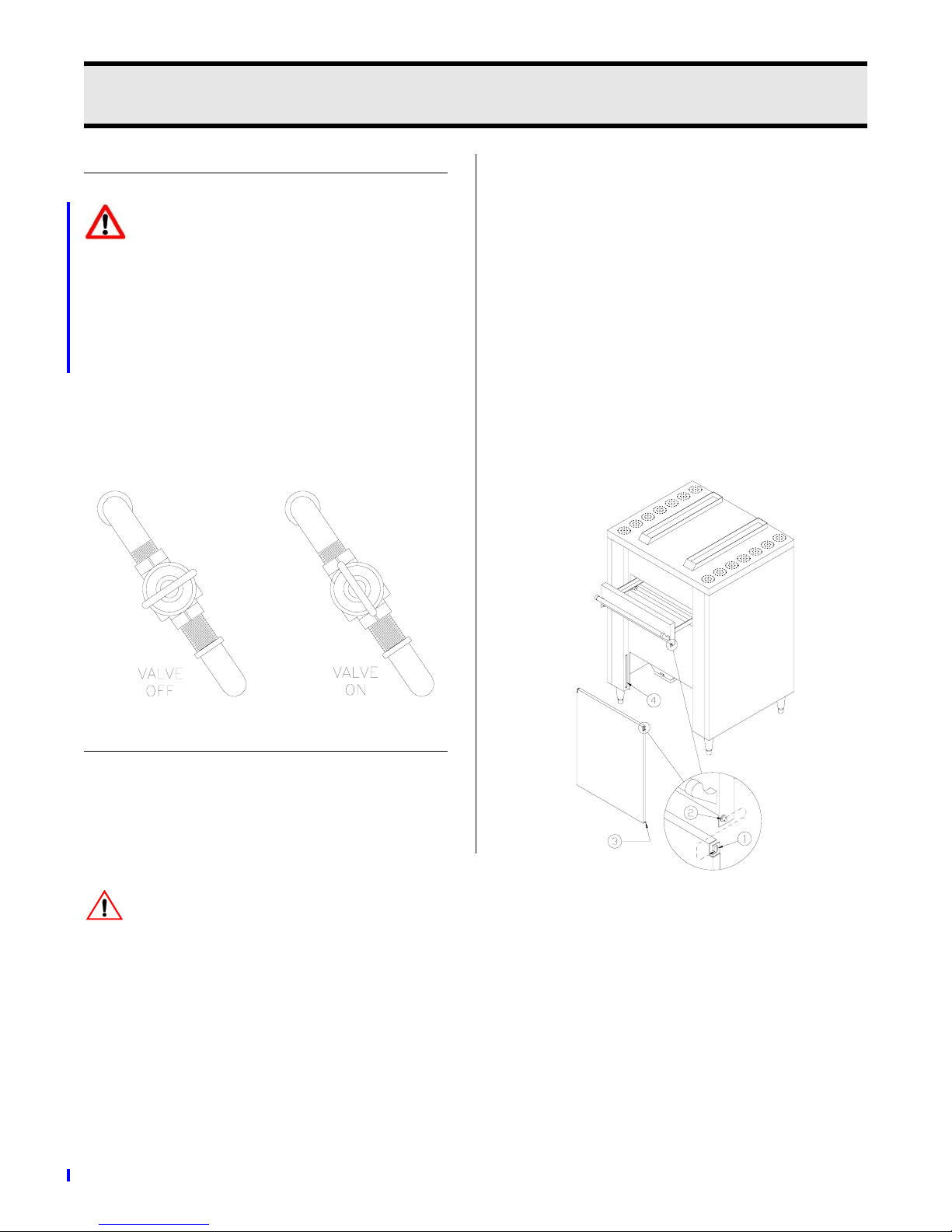
Door Panel:
Clean once daily . Use oven cleaner on hard
to clean surfaces
1. Pull drawer out approximately 4
inches.
2. Push door up and away from you to
disengage door hanger (1) from drawer
pins (2).
3. Tilt door sideways to remove door pin
(3) from slide (4) and remove door.
PARTS REMOVAL
• Disconnect main power supply and shut
main gas supply OFF before cleaning.
• Never clean porcelain finishes while hot.
WARNING: Wait for the unit and oil in
drip pan to completely cool before
cleaning. Hot surfaces or oil could cause
serious burns. DO NOT handle or clean any
surface or component when they are hot.
Manual #13799 5/97 Rev 3/06
5 - 1
Page 24
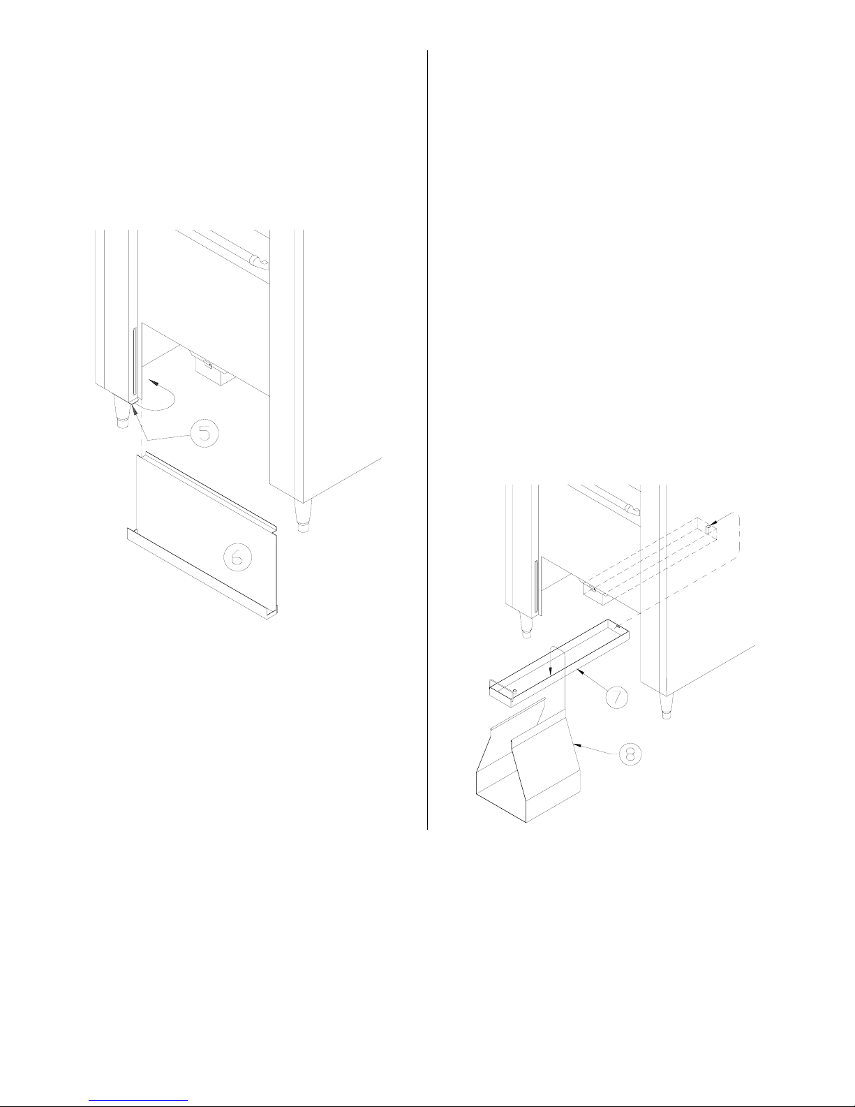
Drip Tray:
Drip Pan:
Clean once daily . Use oven cleaner on hard
to clean surfaces.
1. Rotate retaining clips (5) back.
2. Remove drip tray (6) downward.
Clean once daily . Use oven cleaner on hard
to clean surfaces.
1. Lift up on front of drip pan (7) and
swing handle outward. While supporting condensate pan (half pan), lower
drip pan to allow as much oil as possible to drain into condensate pan.
2. Remove condensate pan (half pan)
from condensate pan support (8).
3. Push drip pan toward the rear of the
unit until drip pan and condensate pan
support can be removed from under
the unit.
4. Remove condensate pan support from
drip pan.
5 - 2
Manual #13799 5/97
Page 25
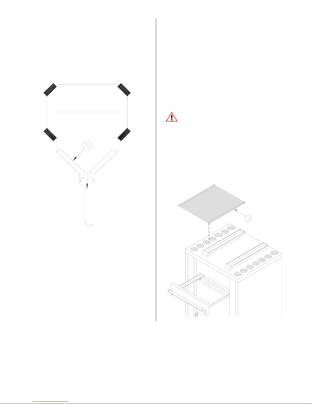
Grease Baffles:
Meat Rack:
Clean once daily . Use oven cleaner on hard
to clean surfaces.
1. From bottom of unit, remove baffles (9)
by raising them above retaining clip
and dropping out of the unit.
Clean once daily. Never wash meat rack
with water or cleaners.
1. Turn POWER ON switch to HIGH.
2. Turn timer to 20 minutes
3. When alarm sounds, turn timer OFF,
open drawer and brush ashes off with
a wire brush.
WARNING: Wait for the unit to com-
pletely cool before removing meat
rack. Hot surfaces could cause serious
burns. DO NOT handle or clean any surface or component when they are hot.
4. Open broiling drawer.
5. Remove meat rack (10).
5 - 3
Manual #13799 5/97
Page 26
CLEANING
WARNING: Rags or papers contain-
ing cooking oil can catch fire if
exposed to heat. Laundering will not
remove the oil. Dispose of all oil-soiled
papers and rags in a trash container that is
in a ventilated area away from all cooking
equipment or other heat sources such as
direct sunlight.
• See individual parts for frequency of
cleaning.
1. Remove all removable parts. See
PARTS REMOVAL.
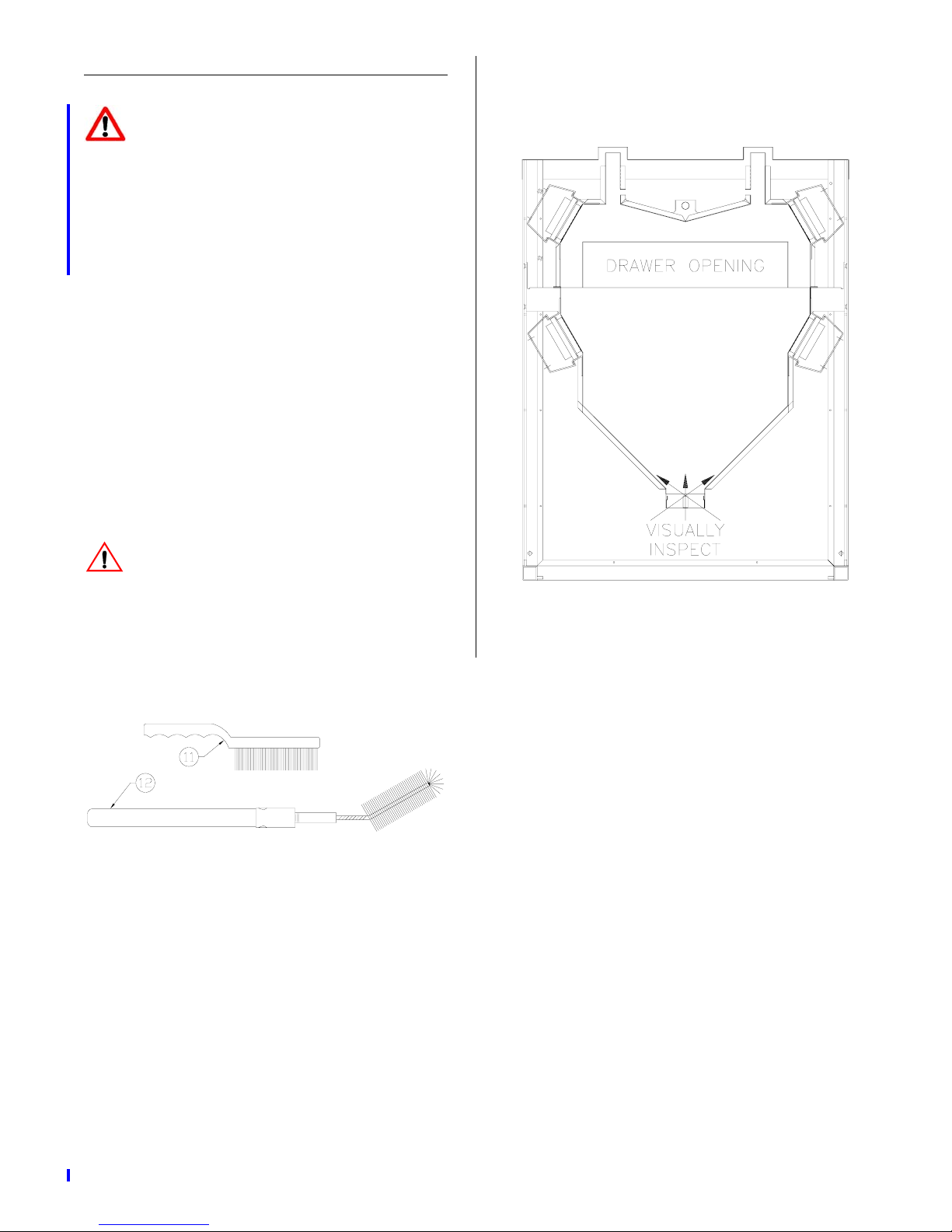
1. Fully open broiling drawer.
2. Using brush (11), reach inside drawer
opening and brush chamber front.
4. With a flashlight, visually inspect thoroughness of cleaning through drawer
opening and bottom chamber opening.
CAUTION: DO NOT remove burners
for cleaning. DO NOT brush burner
surfaces. Burner damage may occur.
3. Using brush (12), reach inside drawer
opening and clean top, sides, and back
of combustion chamber.
5 - 4
Manual #13799 5/97 Rev 3/06
Page 27

PREVENTIVE MAINTENANCE
•DO NOT touch burner surfaces. They
are self cleaning and very fragile.
• Drip pan must be filled to overflow level
with cooking oil before turning unit to
HIGH or LOW.
• Turn main gas valve OFF at the end of
each day.
• DO NOT lubricate bearings for broiling
drawer.
• Be sure to follow manufacturers cleaning, lubrication, and maintenance
instructions for the ventilation system
used to vent your broiler.
5 - 5
Manual #13799 5/97
Page 28
CLEANING
• See individual parts for frequency of
cleaning.
1. Remove all removable parts. See
PARTS REMOVAL.
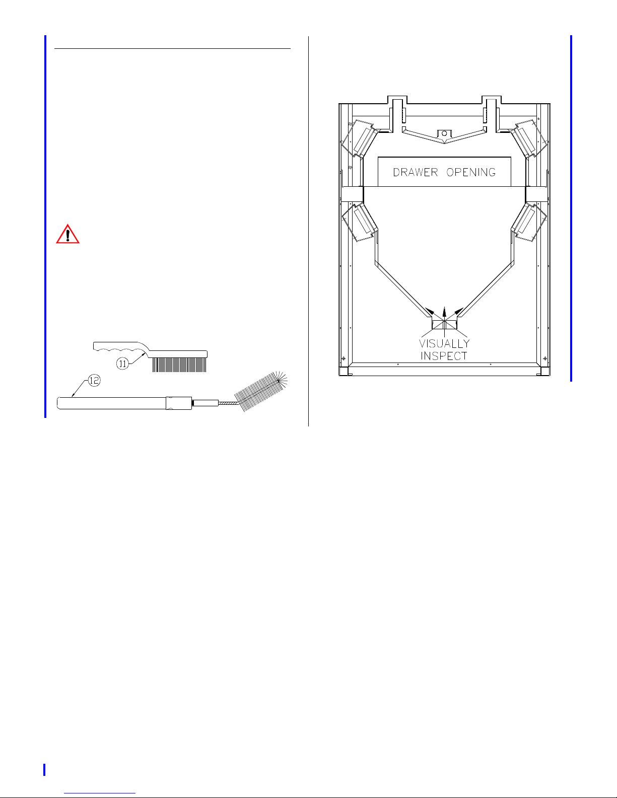
1. Fully open broiling drawer.
2. Using brush (11), reach inside drawer
opening and brush chamber front.
CAUTION: DO NOT remove burners
for cleaning. DO NOT brush burner
surfaces. Burner damage may occur.
3. Using brush (12), reach inside drawer
opening and clean top, sides, and back
of combustion chamber.
4. With a flashlight, visually inspect thoroughness of cleaning through drawer
opening and bottom chamber opening.
Manual #13799 5/97 5 - 4
Page 29

PREVENTIVE MAINTENANCE
• DO NOT touch burner surfaces. They
are self cleaning and very fragile.
• Drip pan must be filled to overflow level
with cooking oil before turning unit to
HIGH or LOW.
• Turn main gas valve OFF at the end of
each day.
• DO NOT lubricate bearings for broiling
drawer.
• Be sure to follow manufacturers cleaning, lubrication, and maintenance
instructions for the ventilation system
used to vent your broiler.
Manual #13799 5/97 5 - 5
Page 30

Page 31

6 - TROUBLESHOOTING
Complaint Cause Remedy
Timer and ignition systems
won’t work.
Timer works but electrodes(s) won’t spark.
Electrodes spark but main
burners won’t ignite
Burner(s) remain in LOW
mode when selector switch i s
on HIGH.
1. Selector switch OFF.
2. Fuse blown.
1. No power to ignition
boards.
2. Ignitor board(s) faulty.
1. Main gas supply OFF.
2. Gas regulator closed.
3. Faulty control board.
4. Gas solenoid faulty.
1. Faulty solenoid.
2. Faulty burner relay.
1. Turn main power ON.
2. Replace fuse.
1. Turn selector switch OFF.
Contact service person.
2. Turn selector switch OFF.
Contact service person.
1. Turn ON.
2. Turn selector switch OFF.
Contact service person.
3. Turn selector switch OFF.
Contact service person.
4. Turn selector switch OFF.
Contact service person.
1. Turn selector switch OFF.
Contact service person.
2. Turn selector switch OFF.
Contact service person.
One or more electrodes will
not spark.
Product not done. 1. No oil or low oil level in
Smoke escaping from stacks
on top of unit.
Manual #13799 5/97 6 - 1
1. Ignitor board in lock-out
mode.
2. Ignitor board faulty.
3. Electrode(s) faulty.
drip pan.
1. No oil or low oil level in
drip pan.
1. Turn selector switch OFF
for 1 minute then to HIGH.
2. Turn selector switch OFF.
Contact service person.
3. Turn selector switch OFF.
Contact service person.
1. Fill drip pan to overflow
level with cooking oil.
1. Fill drip pan to overflow
level with cooking oil.
Page 32

Page 33

 Loading...