

Page 1
INSTALLATION MANUAL
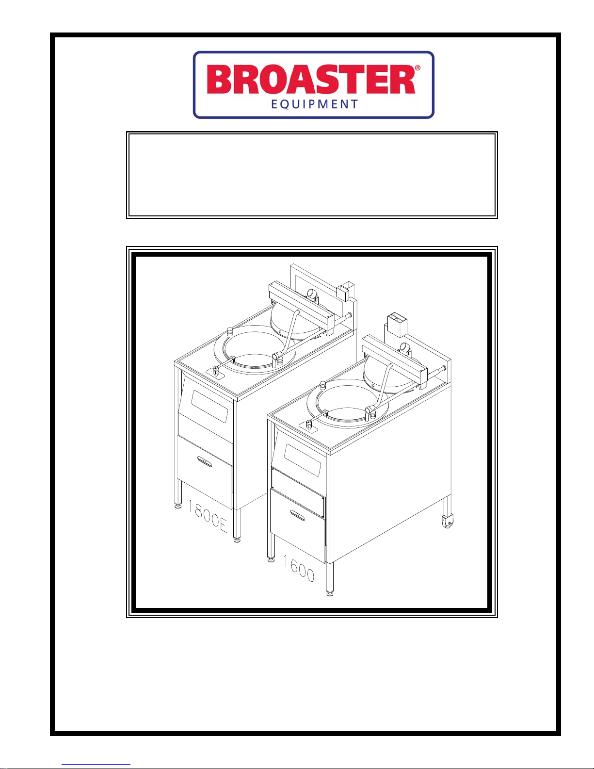
BROASTER® 1600 AND 1800
PRESSURE FRYER
Be sure ALL installers read, understand, and have access to this manual at all times.
Genuine Broaster Chicken®, Broasted®, Broaster Chicken®, Broaster Foods®. and Broasterie® are registered
trademarks. Usage is available only to licensed operators with written authorization from the Broaster Company.
2855 Cranston Road, Beloit, WI 53511-3991
Design Certified By:
1600: CSA, NSF and UL
1800: CSA (AGA & CGA), NSF and UL
The Broaster Company
608/365-0193 broaster.com
#14678 1/99 Rev: 10/14
© 1999 the Broaster Company
Printed In U.S.A.
Page 2

Page 3
All adjustments and repairs shall be made
FOR YOUR SAFETY
Do not use or store gasoline or other flammable vapors
or liquids in the vicinity of this or any other appliance.
Improper installation, adjustments, alteration, service or maintenance can cause
property damage, injury or death. Read the installation, operating and maintenance instructions thoroughly before installing or servicing this equipment.
For the sake of safety and clarity, the following words used in this manual are defined as follows:
Indicates an imminently hazardous situation which, if not avoided, could
result in serious injury or death.
Indicates a potentially hazardous situation which, if not avoided, could
result in serious injury or death.
Indicates a potentially hazardous situation which, if not avoided, could
result in minor injury, property damage or both.
by an authorized Broaster Company representative.
when the cook/filter switch is moved to
If at any time the POWER
ON light does not turn off
the OFF position, contact your local
If there is a power failure, turn cook/filter
switch OFF. On the Model 2400GH, also
Broaster Company representative for
service immediately.
slide switch on gas valve OFF. DO NOT
attempt to operate unit during a power failure.
DO NOT operate unit
without filter pan and filter
pan cover in its proper position. Filter
2400GH: Post, in prominent locations,
instructions to be followed in the event that
pan cover must be wiped clean after
each filtering cycle.
the user smells gas. This information can be
obtained from your local gas supplier.
Make sure Pressure Relief
Valve and Pressure Gauge
Failure to read and
completely could result in serious injury
or death. Be sure ALL operators read,
understand this manual
ports on bottom of cover are clear of any
oil or grease buildup.
1600 Mechanical Controls:
understand and have access to this
manual at all times.
if exposed to heat. Laundering will not
remove the oil. Dispose of all oil-soiled
papers and rags in a trash container that
is in a ventilated area away from all
Rags or paper containing
cooking oil can catch fire
the cook/filter switch is moved to the
cook position, contact your local
If at any time the unit fails
to operate properly when
Broaster Company representative for
service immediately.
cooking equipment or other heat
sources such as direct sunlight.
W-1
broaster.com Manual #14678 1/99 Rev: 2/14
Page 4

1600/1800E Solid State Controls:
If at any time the POWER
ON light does not turn off
when the cook/filter switch is moved to
the OFF position, contact your local
Broaster Company representative for
service immediately.
broaster.com Manual #14678 1/99 Rev: 2/14
W-2
Page 5

TABLE OF CONTENTS
1 - PRE-INSTALLATION ....................................................................................................1 - 1
LOCATION...................................................................................................................1 - 1
CLEARANCE...............................................................................................................1 - 1
LEVELING ...................................................................................................................1 - 1
RECOMMENDED VENTILATION REQUIREMENTS....................................................1 - 2
General Requirements ........................................................................................1 - 2
1600 Hood Dimensions In Inches .......................................................................1 - 3
1800 Hood Dimensions In Inches .......................................................................1 - 4
1600/1800 Hood Dimensions In Millimeters .......................................................1 - 5
2 - FILTER PAN ASSEMBLY ..............................................................................................2 - 1
HARDWARE LIST........................................................................................................2 - 1
ASSEMBLY .................................................................................................................2 - 1
ADDITIONAL ADJUSTMENTS IF NEEDED.................................................................2 - 3
3 - 1600/1800E INSTALLATION.........................................................................................3 - 1
ELECTRICAL CHARACTERISTICS .............................................................................3 - 1
ELECTRICAL CONNECTIONS....................................................................................3 - 1
1600 Suggested Wiring Capacity Table..............................................................3 - 1
1800 Suggested Wiring Capacity Table..............................................................3 - 1
ELECTRICAL HOOK-UP .............................................................................................3 - 2
Access For Hook-Up ..........................................................................................3 - 2
Phase Wiring .......................................................................................................3 - 2
Unit Dimensions For Electrical Hook-Up ............................................................3 - 3
Wiring Diagrams
DOMESTIC:
1600 Mechanical ......................................................................................3 - 4
1600/1800E Solid State............................................................................3 - 8
EXPORT:
1600XP/1800EXP Mechanical ...............................................................3 - 12
1600XP/1800EXP Solid State ................................................................3 - 15
EU:
1600CE Mechanical ...............................................................................3 - 18
1600CE/1800ECE Solid State ................................................................3 - 19
United Kingdom:
1600UK/1800EUK ..................................................................................3 - 20
480V Units:
1800E 480V Δ.........................................................................................3 - 21
1600XP 240/480V...................................................................................3 - 22
1800XP 480V..........................................................................................3 - 24
broaster.com Manual #14678 1/99 Rev 3/14
i
Page 6

4 - 1800GH INSTALLATION ...............................................................................................4 - 1
GENERAL REQUIREMENTS.......................................................................................4 - 1
EU: ......................................................................................................................4 - 1
USA & Canada ....................................................................................................4 - 1
ELECTRICAL CHARACTERISTICS .............................................................................4 - 2
ELECTRICAL CONNECTIONS....................................................................................4 - 2
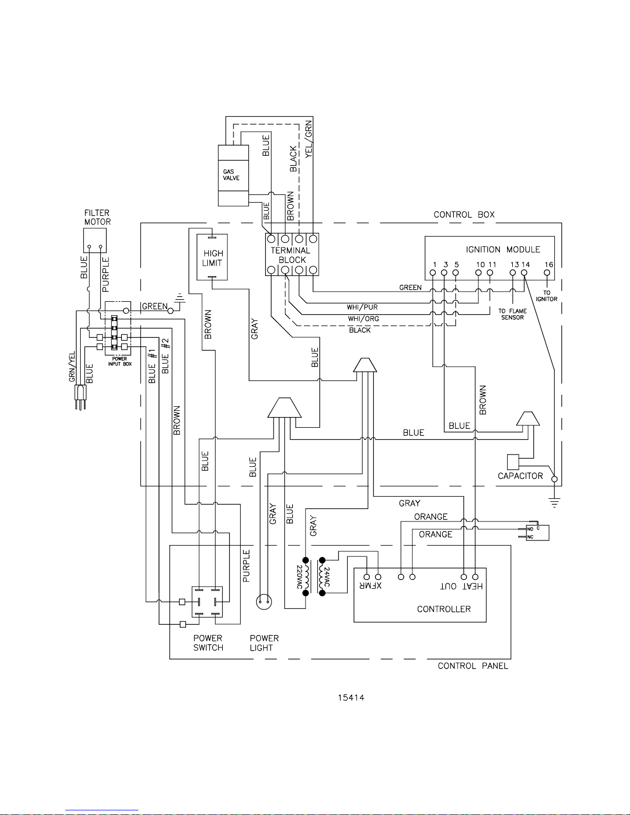
WirIng Diagrams ....................................................................................................4 - 2
DOMESTIC: 1800GH .........................................................................................4 - 2
EXPORT: 1800GH .............................................................................................4 - 3
EU: 1800GHCE .................................................................................................4 - 4
EU: 1800GHCE for United Kingdom..................................................................4 - 5
GAS CHARACTERISTICS ...........................................................................................4 - 6
BTU/HR Ratings..................................................................................................4 - 6
Gas Pressure And Orifices..................................................................................4 - 6
Gas Conversion ..................................................................................................4 - 6
High Altitude .......................................................................................................4 - 6
GAS PIPING ................................................................................................................4 - 7
Unit Dimensions For Gas Hook-Up ....................................................................4 - 7
Example Of Piping System Design .....................................................................4 - 8
5 - OPERATIONAL CHECK-OUT ......................................................................................5 - 1
COVER ASSEMBLY ....................................................................................................5 - 1
INITIAL STARTUP
Electric .............................................................................................................. 5 - 1
Gas .....................................................................................................................5 - 2
1800GH LIGHTING INSTRUCTIONS ..........................................................................5 - 2
Start-Up ..............................................................................................................5 - 2
Shut Down ..........................................................................................................5 - 3
AIR SHUTTER ADJUSTMENT ...................................................................................5 - 3
broaster.com Manual #14678 1/99 Rev: 3/14
ii
Page 7

1 - PRE-INSTALLATION
LOCATION
For convenience and speed, location of the
unit should be given careful consideration.
If possible, locate the unit so the flow of
cooked product is in a straight line from
storage, in and out of the unit and to the
customer. Landing tables should be provided on at least one side of the unit.
• To avoid splashing of hot liquid, unit
must be restrained to prevent tipping.
This can be done by installing the unit in
a battery of appliances, in an alcove or
with adequate ties
• Provision must be made to eliminate
movement of the unit which might cause
strain on electrical and gas connections.
• DO NOT install unit where traffic areas
are on either side or in back of unit.
CLEARANCE
USA & EU:
Gas units are to be installed only in noncombustible locations. Minimum clearances for non-combustible construction is 0 inches from sides and 6 inches
from back.
CANADA:
Gas units are certified for installation on
a combustible floor. Minimum clearances for combustible construction is 1
inch from sides and 6 inches from back.
LEVELING
Adjust front feet to level entire unit. Add
additional blocking if necessary on a sloping floor.
1-1
broaster.com Manual #14678 1/99 Rev 2/14
Page 8

RECOMMENDED VENTILATION
General Requirements:
REQUIREMENTS
Exhaust hood should comply with ANSI/
NFPA #96 or national, state and local
codes. All units must be under an adequate
power exhaust hood for ventilation of cooking vapors and products of combustion.
Precautions should be taken in the design
of the exhaust hood to avoid interference
with operation of the unit. Consult a local
ventilation company for fire suppression,
design and installation of a hood.
DO NOT extend the
exhaust stack or exhaust
flue of any unit. Doing so may cause a negative back draft causing malfunction and
interference with burner operation on the
1800GH and improper exhausting of cooking vapors on all units.
1. Exhaust hood must conform to applicable national, state and local codes.
2. It is recommended that requirements
of the National Fire Protection Association (NFPA), Standard No. 96 be followed for the design, installation and
use of exhaust system components.
This includes hoods, grease removal
devices, exhaust ducts, dampers, air
moving devices, auxiliary equipment
and fire extinguishing equipment for
the exhaust system and the cooking
equipment used therewith in commercial, industrial, institutional and similar
cooking applications.
3. Hood Size: The overhead canopy
type hood should be sized to completely cover the equipment it is
designed to ventilate plus an overhang
of at least 6 inches on all sides of
equipment not immediately adjacent
to walls or other construction extending above the cooking surface. Noncanopy, prefabricated “backshelf”
type hoods should be sized according
to the manufacturers specifications.
4. Exhaust Air Volume (minimum):
Canopy hood open on all four sides:
1800 cu. ft./minute. Canopy hood
open on three sides or less: 1200 cu.
ft./minute.
5. Exhaust Air Velocity: All exhaust
ducts should be sized to provide an air
velocity in the ducts of at least 1500
ft./minute.
1-2
broaster.com Manual #14678 1/99 Rev 2/14
Page 9
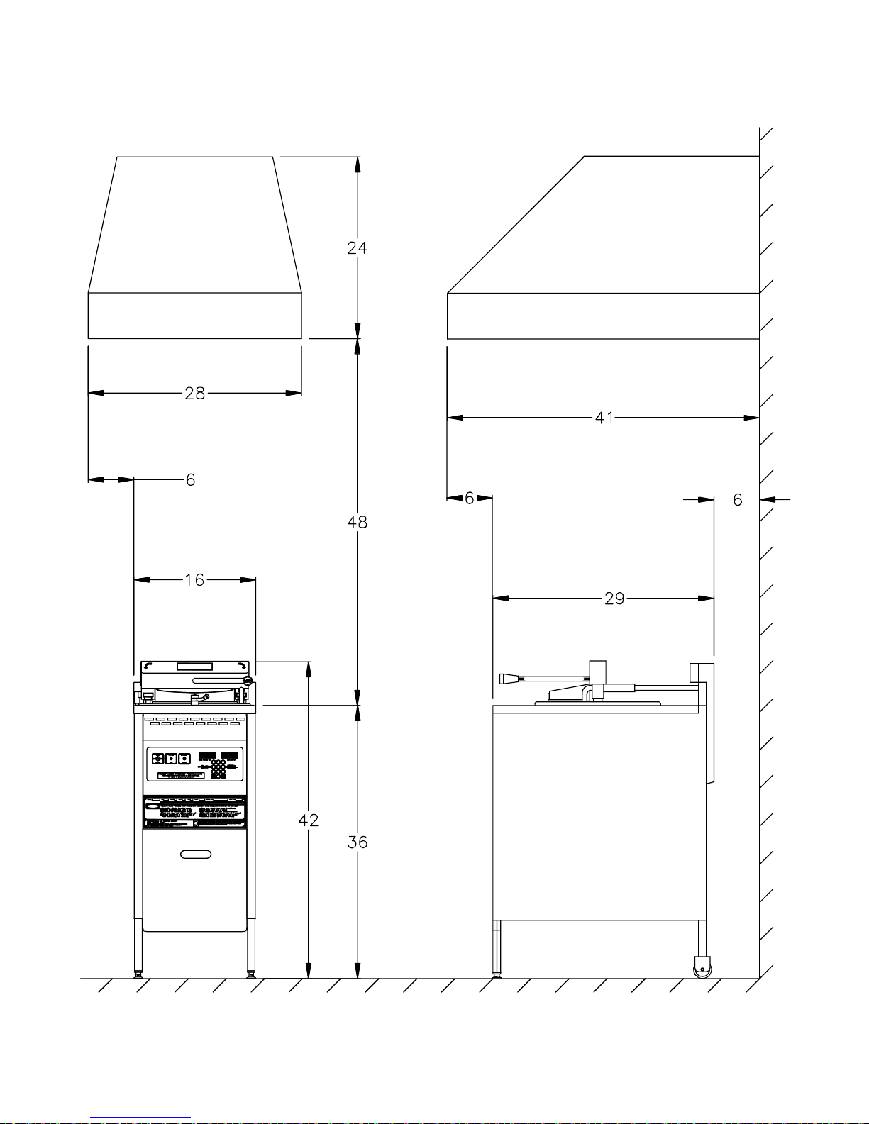
1600 Hood Dimensions In Inches:
DANGER
MAXIMUM WORKING
PRESSURE 15 PSI
BEFORE OPERATINGCHECK OIL LEVELCAUTION!
0
21
475
8
3
6
9
MADE IN U.S.A.
SAFETY AND OPERATIN G INSTRUCTIONS
NSF
MANUFACT URED BY THE BROA STER COM PANY
MODEL 1600
UNLESS PRESSURE IS AT ZERO P.S.I.
DO NOT O PEN COVER
COVER CLOSED
COVER OPEN
1-3
broaster.com Manual #14678 1/99 Rev 2/14
Page 10

1800 Hood Dimensions In Inches:
1-4
broaster.com Manual #14678 1/99 Rev 2/14
Page 11
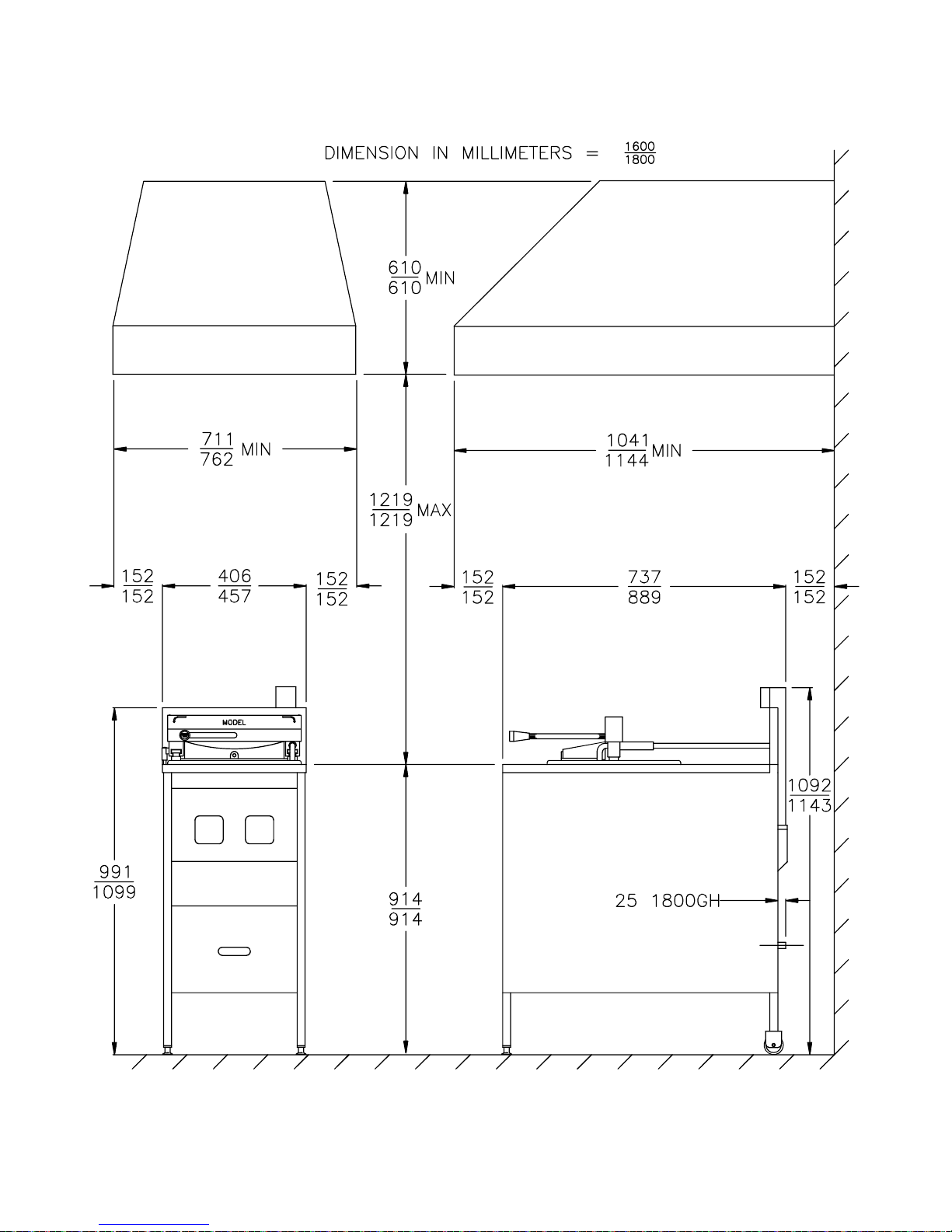
1600/1800 Hood Dimension In
Millimeters:
1-5
broaster.com Manual #14678 1/99 Rev 2/14
Page 12

Page 13
2 - FILTER PAN ASSEMBLY
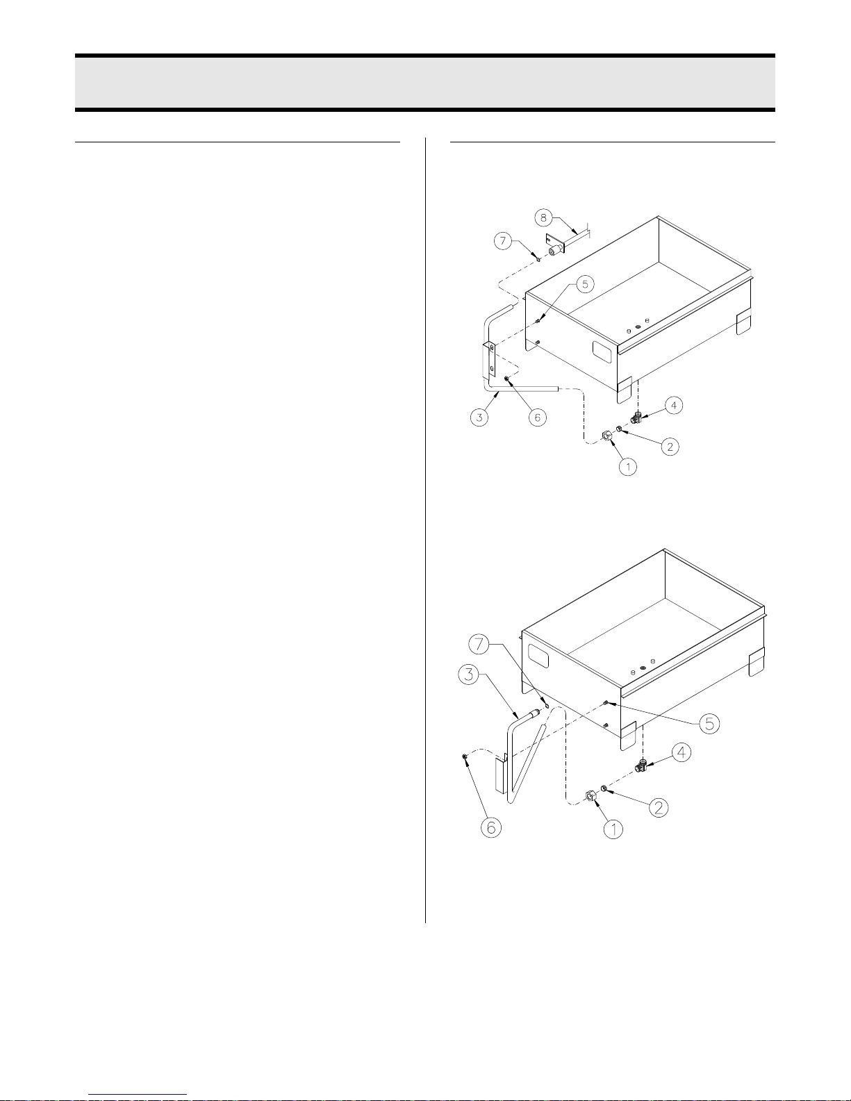
HARDWARE LIST
1600:
1 - Compression Nut #02536 (1)
2 - Brass Ferrule #02537 (1)
3 - Riser Line #11314 (1)
6 - Keps Nut #00522 (2)
7 - O-ring #09883 (3)
9 - Nipple #08696 (1)
1800:
1 - Compression Nut #02536 (1)
2 - Brass Ferrule #02537 (1)
3 - Riser Line #11308 (1)
6 - Keps Nut #00522 (2)
7 - O-ring #09883 (3)
ASSEMBLY
1600:
1800:
1. From bag of hardware, install compression nut (1) then ferrule (2) onto
riser line (3).
2-1
broaster.com Manual #14678 1/99 Rev 2/14
Page 14
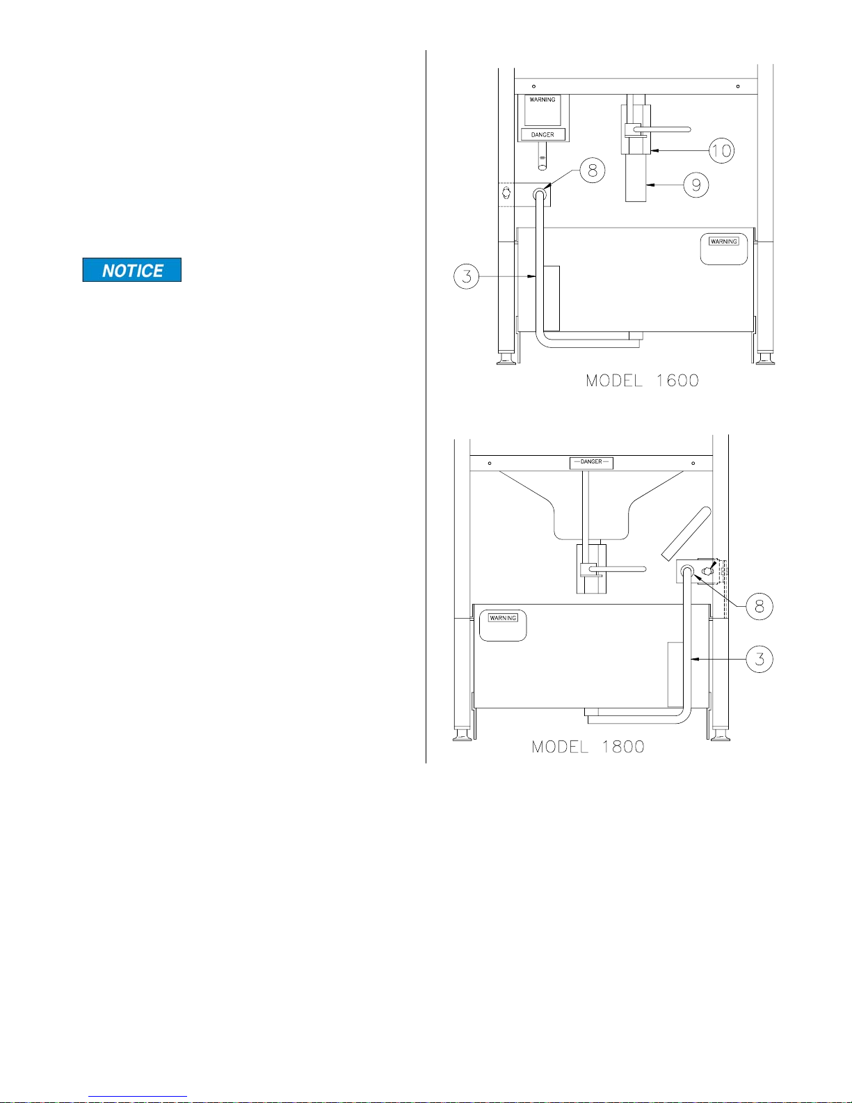
2. Install riser line (3) onto pan. First
install line into elbow (4) on bottom
center of pan while handle fits over
studs (5) on front of pan.
3. Install keps nuts (6) onto studs (5) but
do not tighten.
4. Tighten nut onto elbow (4).
Elbow may have to be
turned with a wrench if nut
will not start onto elbow.
5. .Lubricate O-ring (7) with cooking oil.
1600: Install O-ring (7) into inner
groove in suction line (6). Screw nipple
(9) into drain valve (10).
1800: Install O-ring (7) into groove on
riser line (3).
6. Install filter pan under unit and align
riser line (3) with suction line (8).
7. Tighten keps nuts (6) mounting riser
line (3) to filter pan.
8. See Operation Manual for additional
assembly.
2-2
broaster.com Manual #14678 1/99 Rev 2/14
Page 15
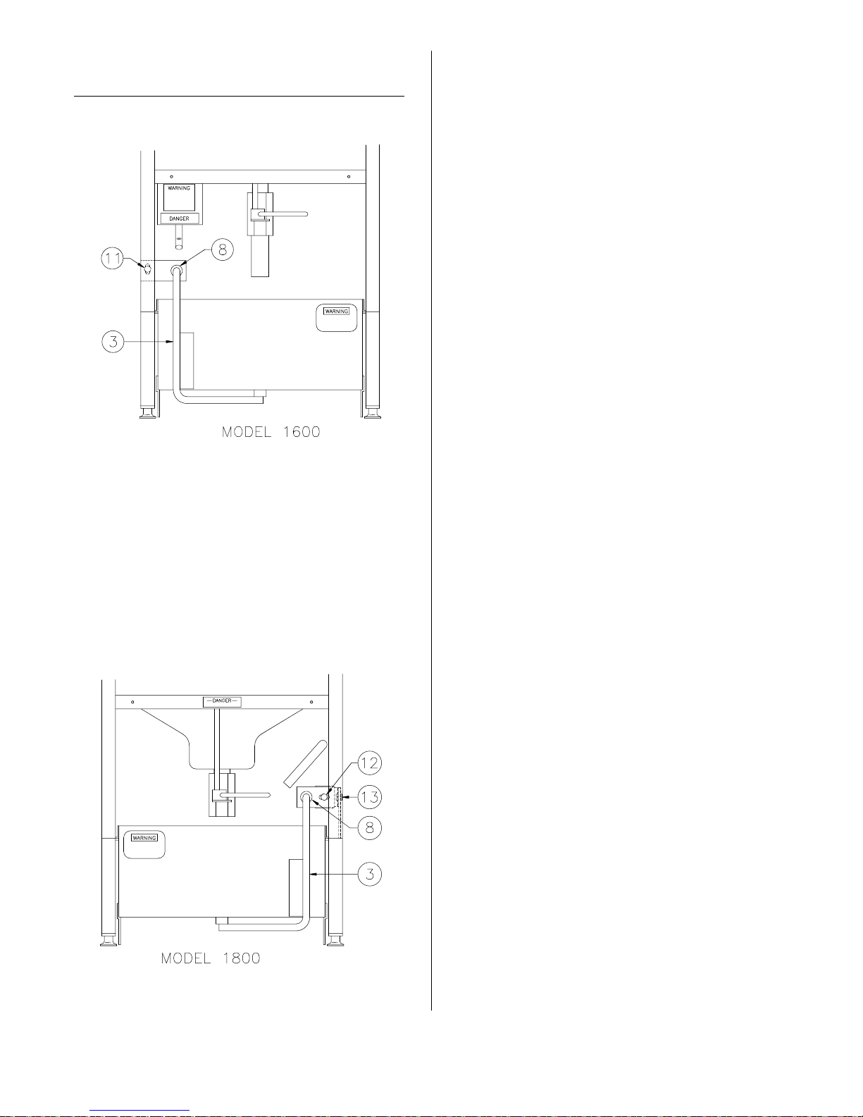
ADDITIONAL ADJUSTMENTS
2. Loosen bolt (12) and nut and bolt (13).
IF NEEDED
1600:
1. Loosen nut and bolt (11).
3. Push pan under unit. By hand, move
suction line (8) until riser line (3) is fully
inserted into suction line.
4. Tighten all nuts and bolts.
5. Replace side panel
2. Push pan under unit. By hand, move
suction line (8) until riser line (3) is fully
inserted into suction line.
3. Tighten all nuts and bolts.
1800:
1. Remove side panel.
2-3
broaster.com Manual #14678 1/99 Rev 2/14
Page 16

Page 17
3 - 1600/1800E INSTALLATION
ELECTRICAL CHARACTERISTICS
These models are available for either 208,
240 or 480 applied voltage, 60Hz, 3 phase
electrical connection in the USA and several voltages for export applications.
Be sure to check the wiring diagram located
inside the front panel. It shows electrical
circuits and connections. See Access For
Hook-Up under ELECTRICAL HOOK-UP.
• All electrical work must conform with the
requirements of national, state and local
electrical codes.
• When installing or servicing the unit,
always check the dataplate located on
the front panel (1600) or toward the rear
of the counter top (1800) to make certain proper parts are used and the correct service rendered. DO NOT apply a
voltage to any unit other than that
shown on the dataplate. If in doubt,
consult your local power company.
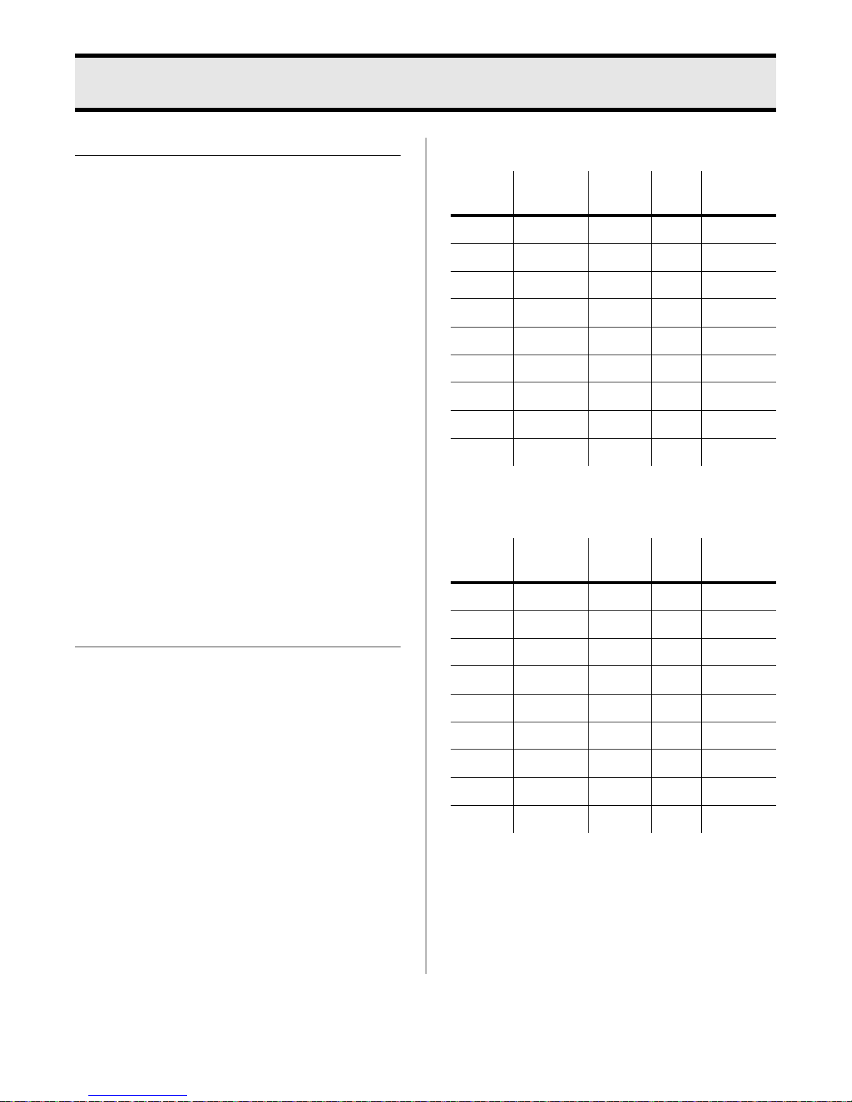
1600 Suggested Wiring Capacity Table:
Phase Volts Amps Wire
1 208 29 #8 40
1 220 30.5 #8 40
1 230 26 #8 40
1 240 27 #8 40
3 208 17 #10 25
3 240 16 #10 20
3 220/380 10.2 #10 15
3 230/400 8.7 #10 15
3 240/415 9.1 #10 15
Breaker
or Fuse
1800E Suggested Wiring Capacity Table:
Phase Volts Amps Wire
1 208 48 #8 60
Breaker
or Fuse
ELECTRICAL CONNECTIONS
• A remote circuit breaker or fuse should
be installed in main power supply
located in a path of exit and clearly identified.
• When installed, the unit must be electrically grounded in accordance with local
codes, or in the absence of local codes,
with the National Electrical Code, ANSI/
NFPA 70, or for Canada, the Canadian
Electrical Code, CSA C22.2, as applicable.
• Use copper wire only for connections.
• If power run is over 50 feet, use next
larger size wire.
1 220 50 #8 60
1 230 43 #8 60
1 240 45 #8 60
3 208 28 #8 40
3 240 26 #8 40
3 220/380 16.8 #10 20
3 230/400 14.3 #10 20
3 240/415 15 #10 20
broaster.com Manual #14678 1/99 Rev 2/14
3-1
Page 18
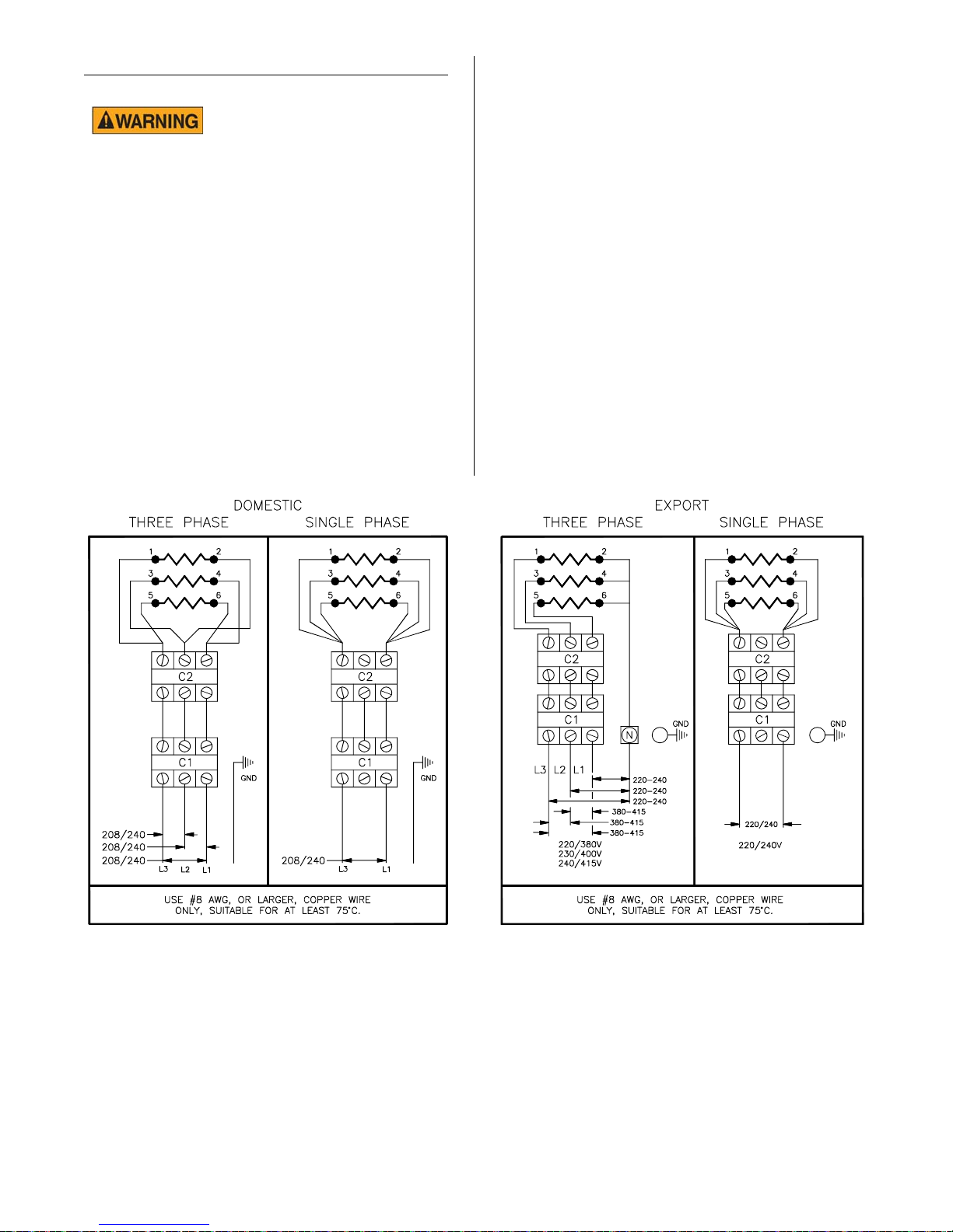
ELECTRICAL HOOK-UP
3Ph 50/60Hz
1Ph. 50/60Hz
WARNING: Disconnect
main power supply and
turn unit OFF before installing power supply
to the unit. High voltage may be encountered. Only persons trained and equipped
for checking high voltage shall perform
electrical connections.
Access For Hook-Up:
Phase Wiring:
Phase wiring diagram is located inside the
front panel. See Access For Hook-Up
under ELECTRICAL HOOK-UP.
Electric units are shipped from the factory
wired for 3 phase. In this case, applied
voltage must be connected to L1, L2 and
L3 of contactor C1 and a ground wire to the
GND connector.
1. Disconnect main power supply.
2. Remove condensate pan and one
screw (1600) or two screws (1800)
from bottom of front panel. Pull out
and down on bottom to remove.
For single phase operation, remove both
element wires from the center connector of
contactor C2. Install wire #3 with wires #1
and #5 and install wire #2 with wires #4 and
#6. In this case, applied voltage must be
connected to L1 and L3 of contactor C1
and a ground wire to the GND connector.
Note: Check all contactor screw connections to be sure they are fully tightened for proper
electrical continuity.
broaster.com Manual #14678 1/99 Rev 2/14
3-2
Page 19
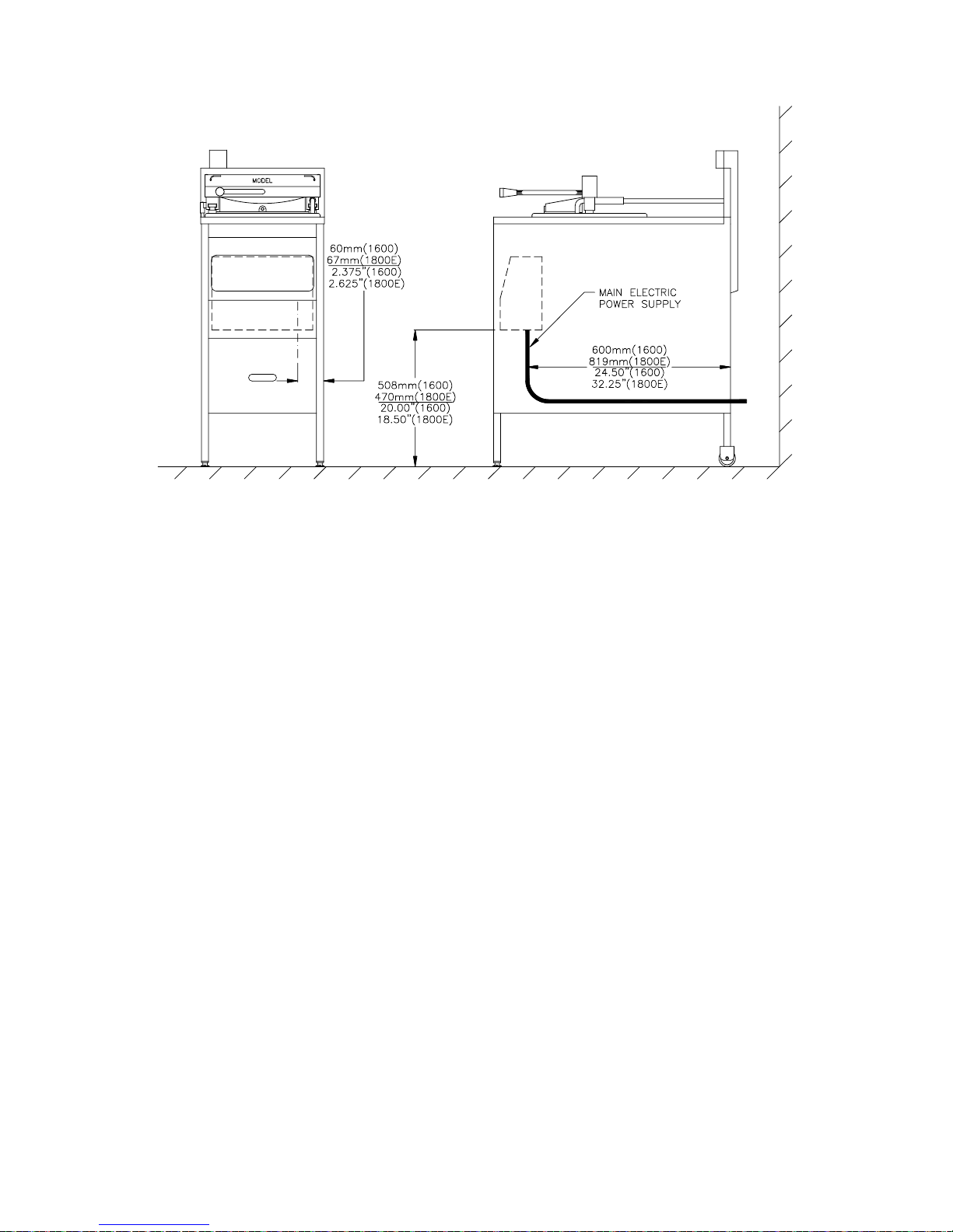
Unit Dimensions For Electrical Hook-Up:
broaster.com Manual #14678 1/99 Rev 2/14
3-3
Page 20
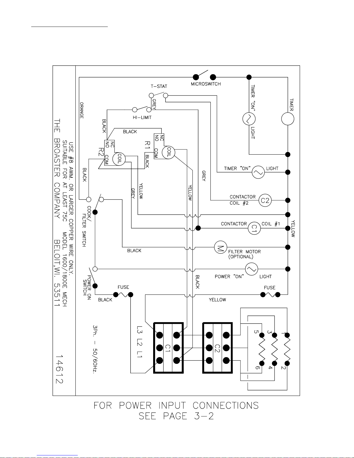
WIRING DIAGRAMS
Wiring diagrams are located inside front panel. See Access For Hook-up under ELECTRICAL
HOOK-UP.
1600 Mechanical 208 or 240VAC:
broaster.com Manual #14678 1/99 Rev 2/14
3-4
Page 21
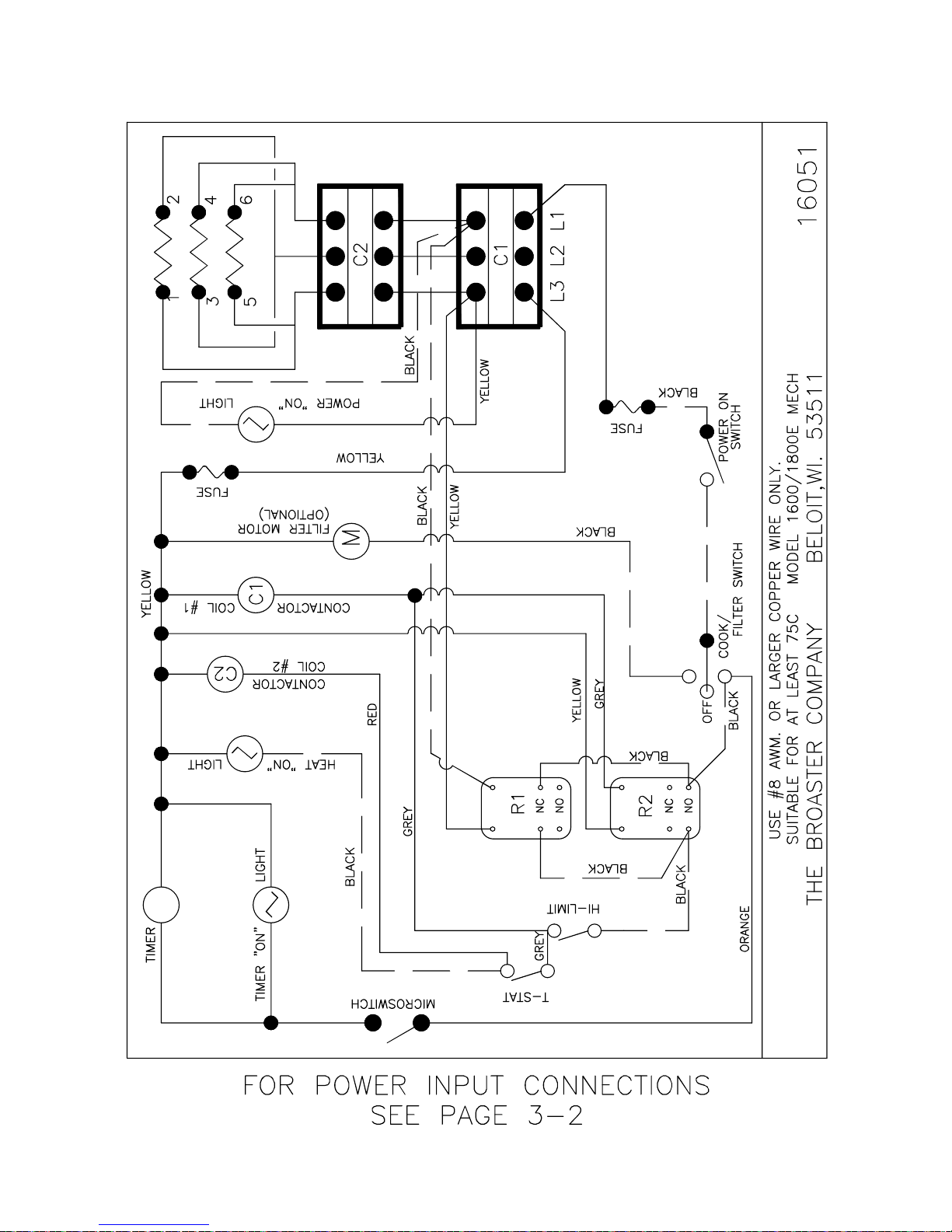
1600 Mechanical 208 or 240VAC: Effective E16E401073
3
6
4
1
2
5
4
6
3
1
2
5
E18C401133
3-5
broaster.com Manual #14678 1/99 Rev 2/14
Page 22
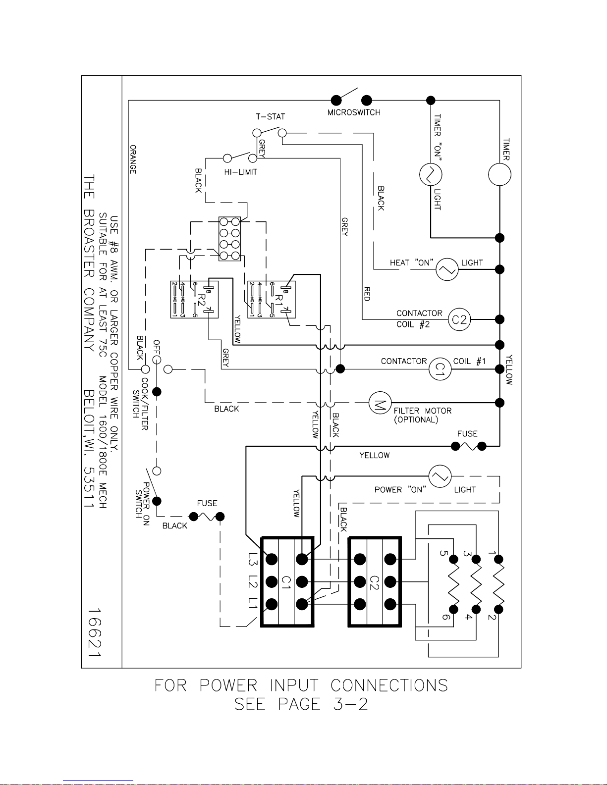
1600 Mechanical 208 or 240VAC: Effective E16A700023
E18A700043
broaster.com Manual #14678 1/99 Rev 2/14
3-6
Page 23
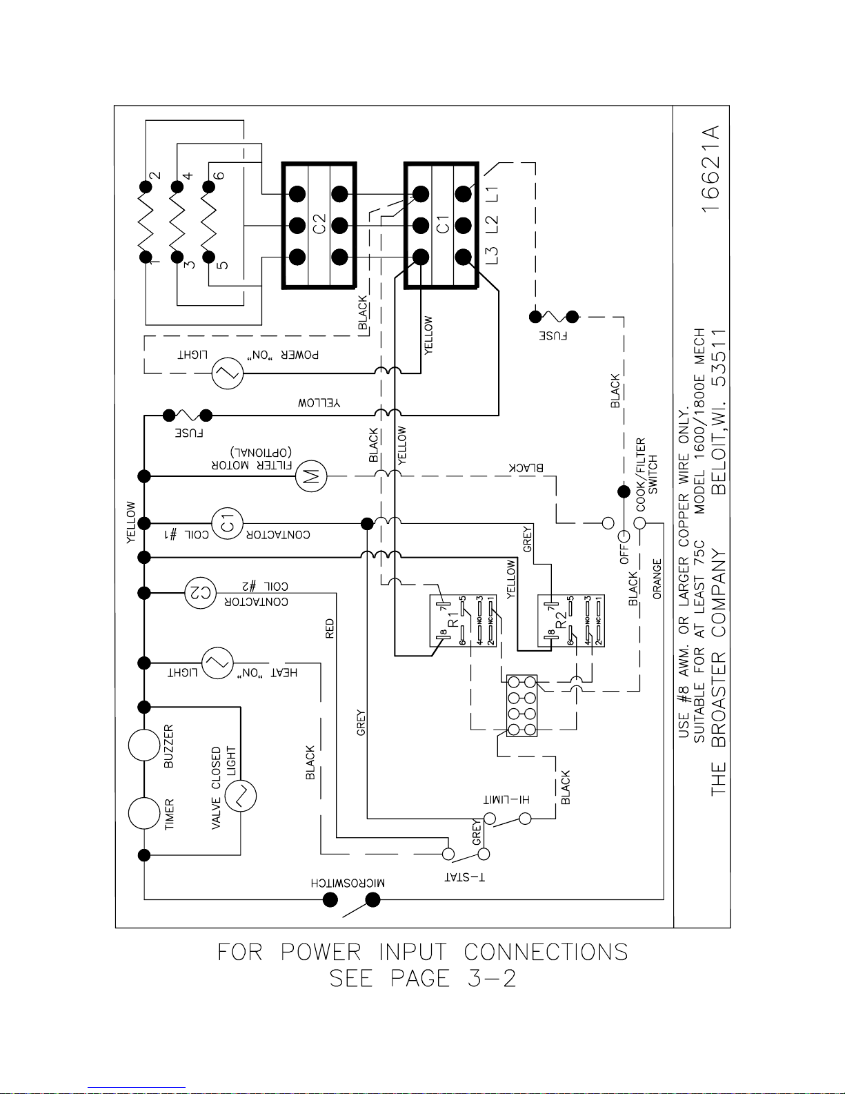
1600 Mechanical 208 or 240VAC: Effective E16L700000
E18K700000
broaster.com Manual #14678 1/99 Rev 2/14
3-7
Page 24
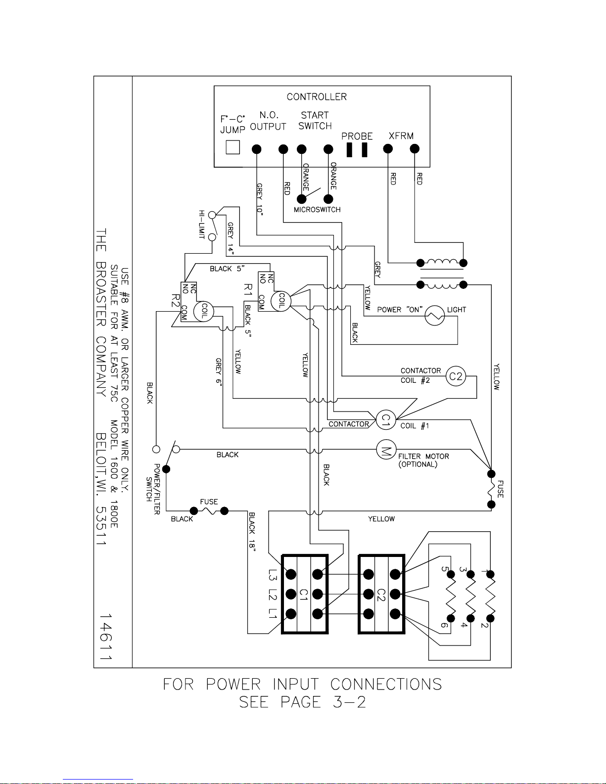
1600/1800E Solid State 208 or 240VAC:
broaster.com Manual #14678 1/99 Rev 2/14
3-8
Page 25
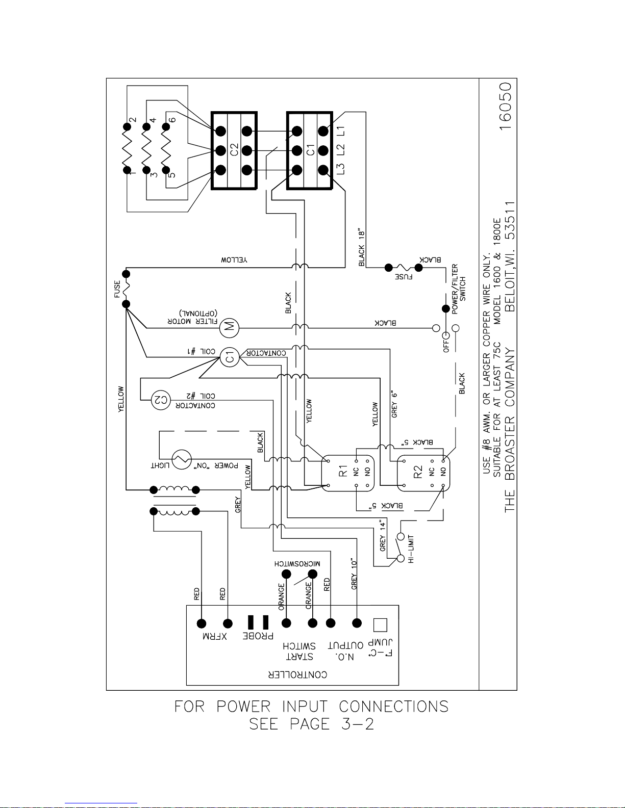
1600/1800E Solid State 208 or 240VAC: Effective SE6E401073
6
4
2
5
3
1
4
6
5
2
1
3
SE8C400951
3-9
broaster.com Manual #14678 1/99 Rev 2/14
Page 26
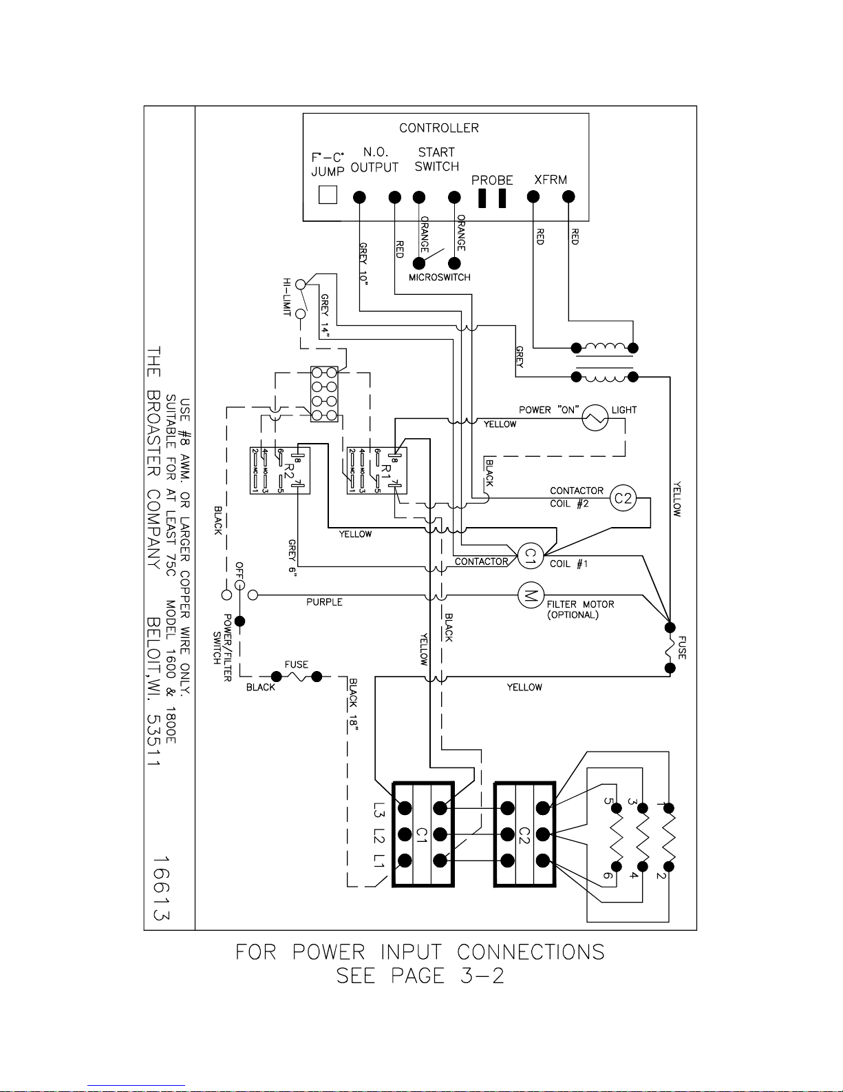
1600/1800E Solid State 208 or 240VAC: Effective SE6A700013
SE8A700011
broaster.com Manual #14678 1/99 Rev 2/14
3-10
Page 27

1800E Solid State 208 or 240VAC: Effective - SE8I213193
2
5
1
346
broaster.com Manual #14678 1/99 Rev 2/14
3-11
Page 28
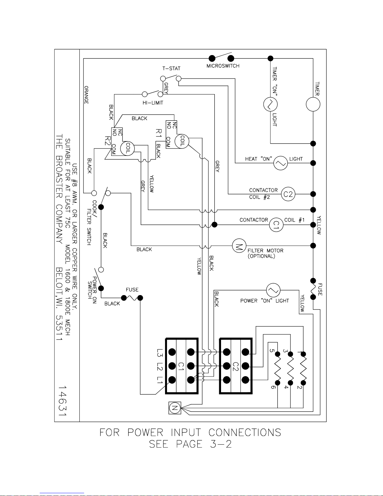
EXPORT: 1600XP/1800EXP Mechanical:
broaster.com Manual #14678 1/99 Rev 2/14
3-12
Page 29
3
6
4
1
2
5
4
6
3
1
2
5
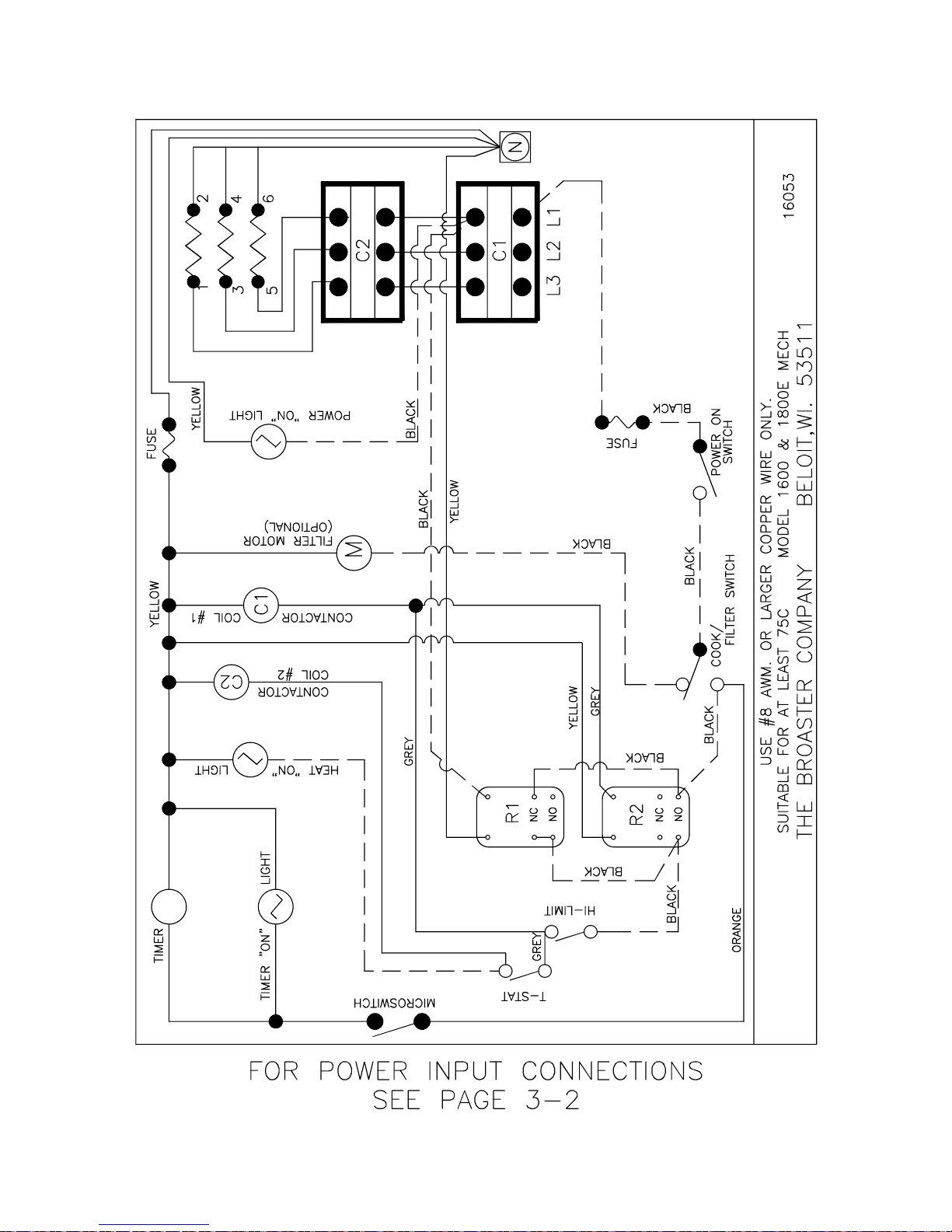
EXPORT: 1600XP/1800EXP Mechanical: Effective E16E401073
E18D401133
3-13
broaster.com Manual #14678 1/99 Rev 2/14
Page 30
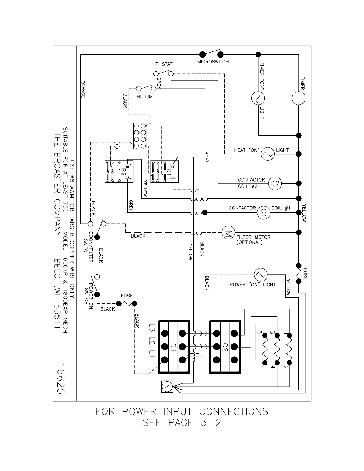
EXPORT: 1600XP/1800EXP Mechanical: Effective E16A700023
E18A700043
broaster.com Manual #14678 1/99 Rev 2/14
3-14
Page 31
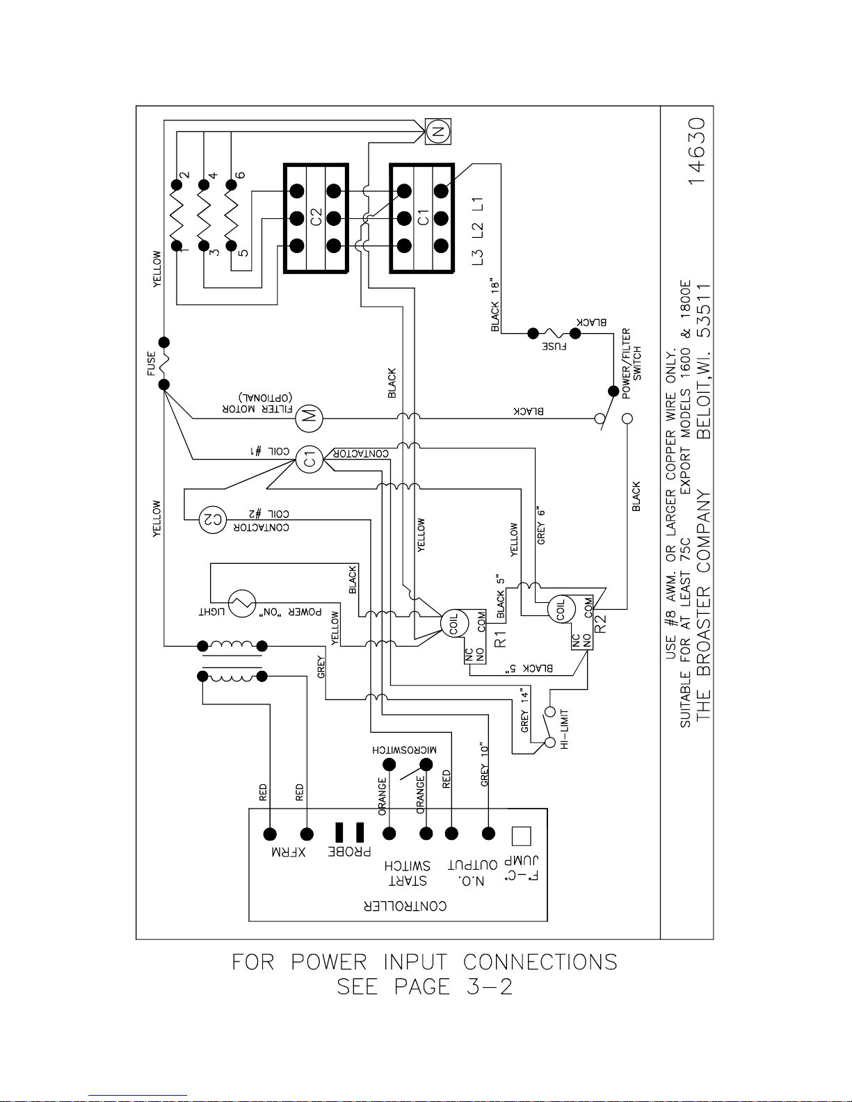
EXPORT: 1600XP/1800EXP Solid State:
broaster.com Manual #14678 1/99 Rev 2/14
3-15
Page 32
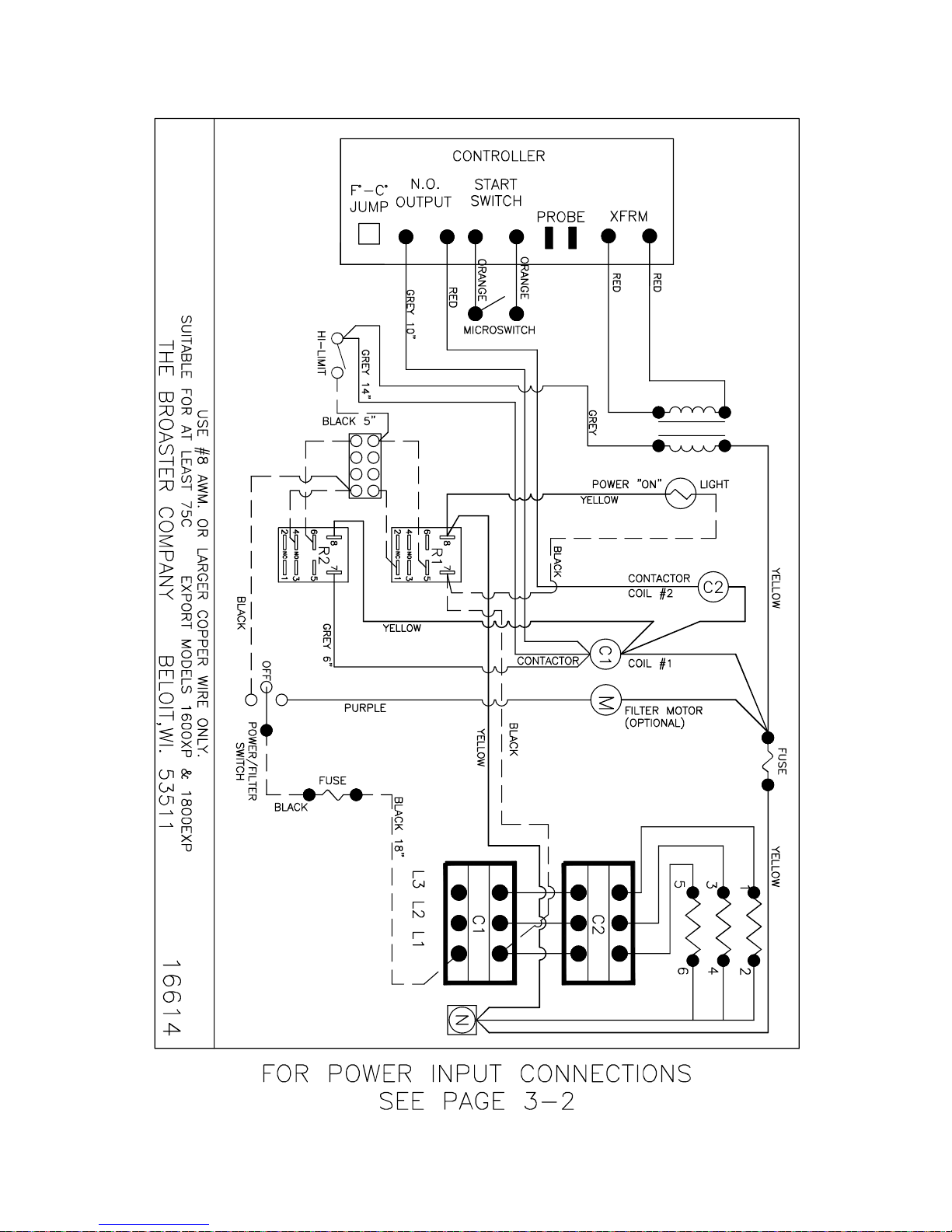
EXPORT: 1600XP/1800EXP Solid State: Effective SE6A700013
SE8A700011
broaster.com Manual #14678 1/99 Rev 2/14
3-16
Page 33
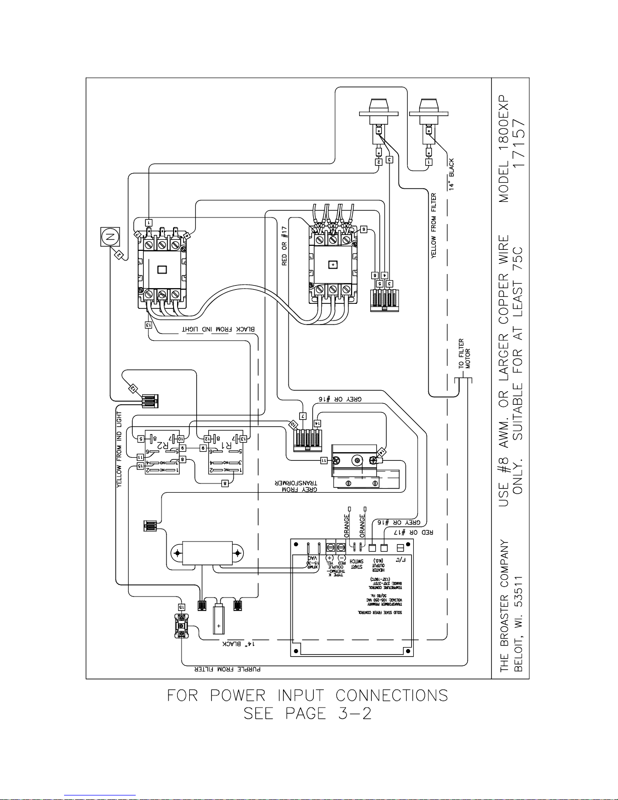
1800EXP Solid State 208 or 240VAC: Effective - SE8I213193
2
5
1
346
broaster.com Manual #14678 1/99 Rev 2/14
3-17
Page 34
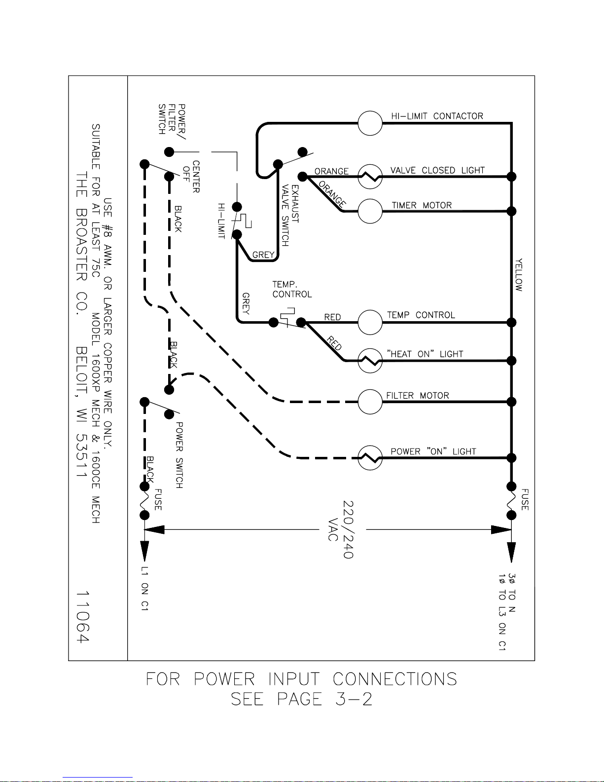
EU: 1600CE MECHANICAL:
M
C2C1
TM
broaster.com Manual #14678 1/99 Rev 2/14
3-18
Page 35
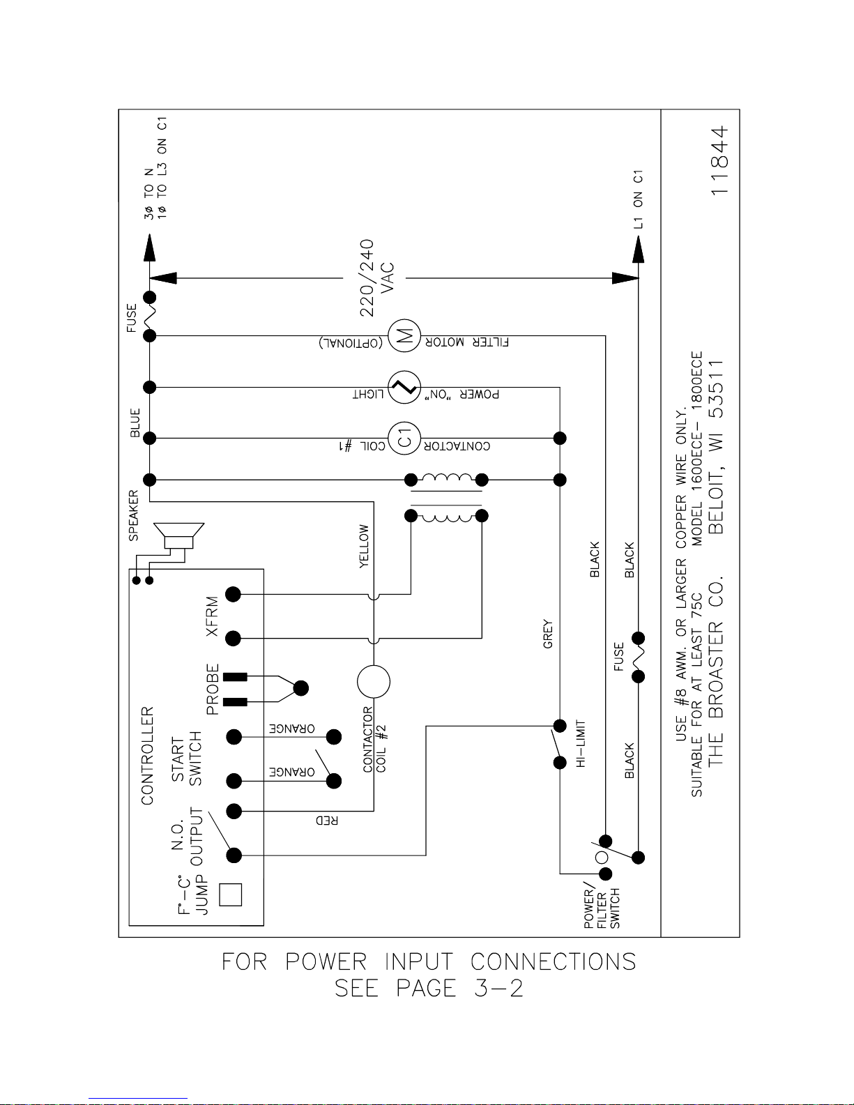
C2
EU: 1600CE/1800ECE SOLID STATE:
3-19
broaster.com Manual #14678 1/99 Rev 2/14
Page 36
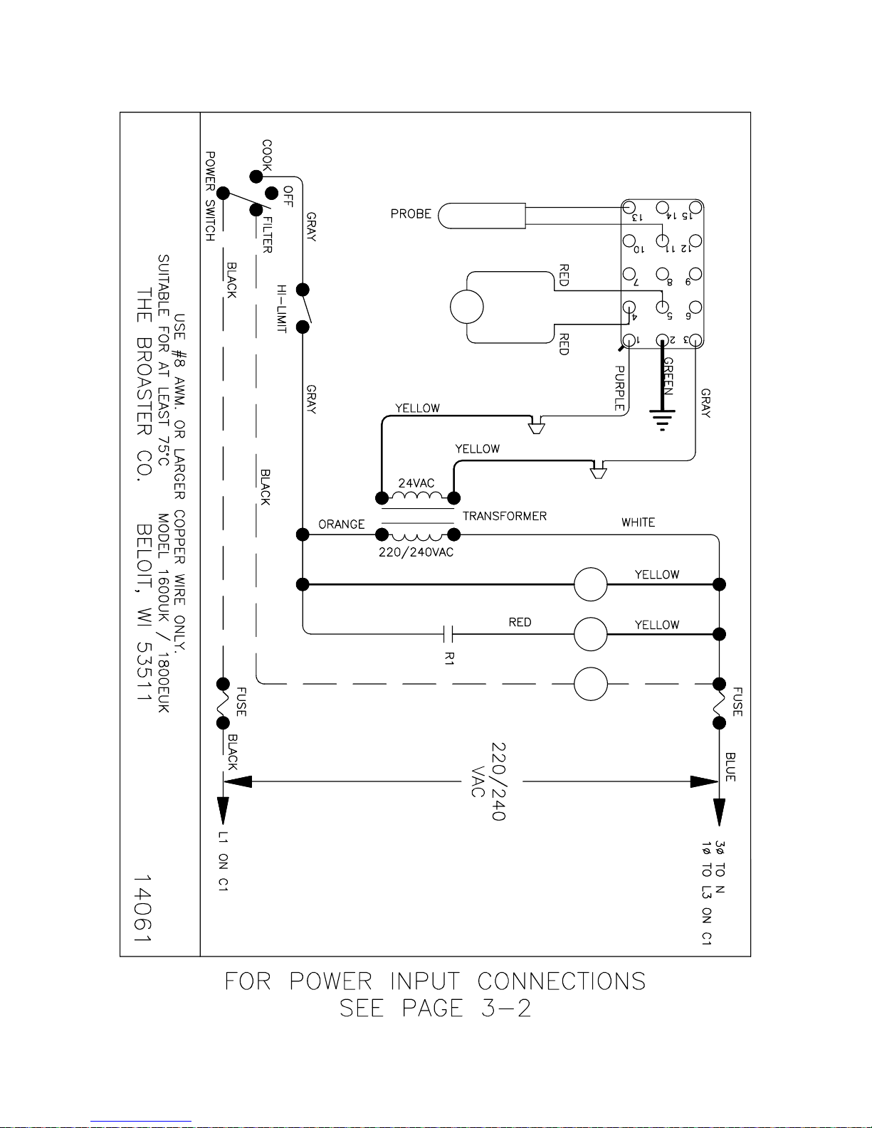
M
C1 C2
R1
EU: 1600UK/1800EUK SOLID STATE:
3-20
broaster.com Manual #14678 1/99 Rev 2/14
Page 37
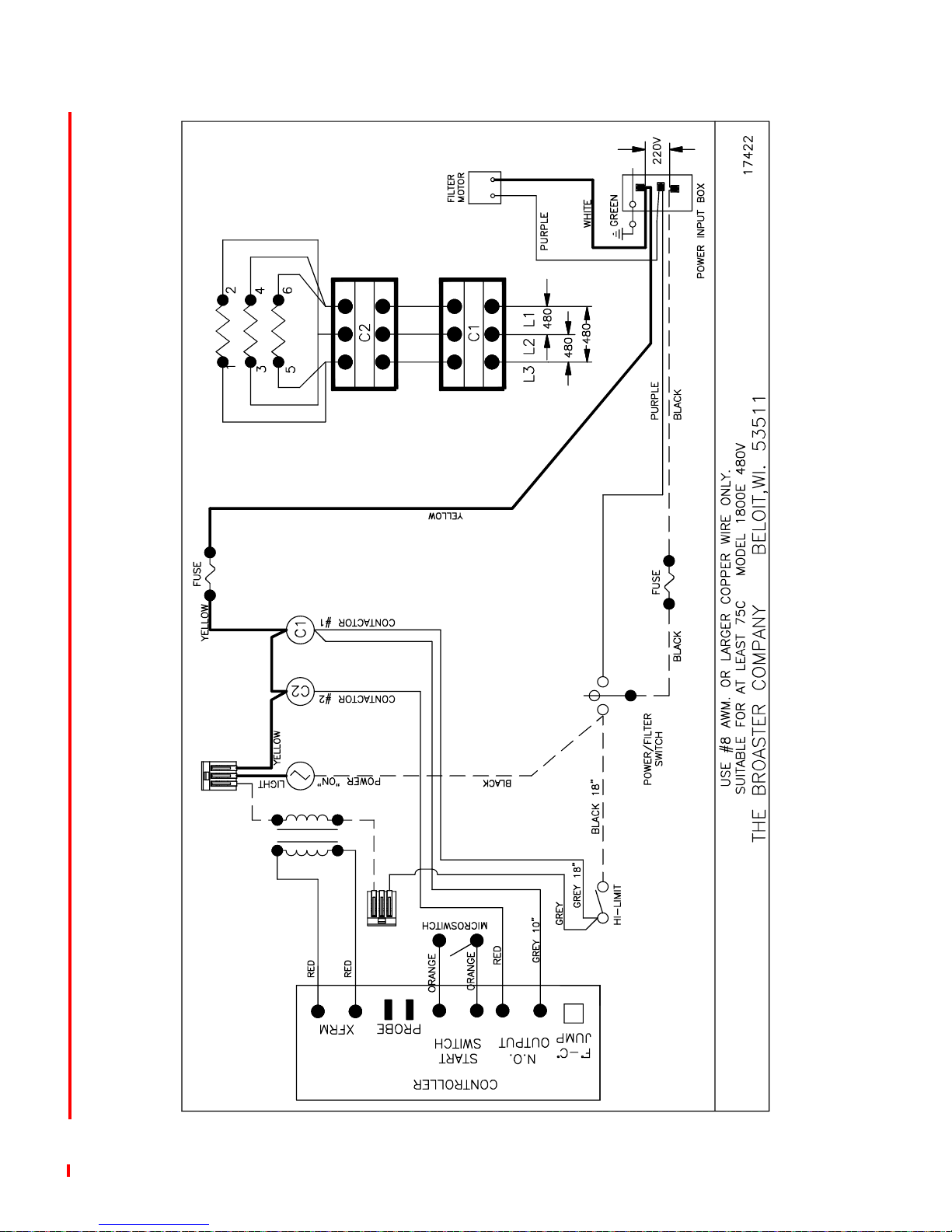
1800E Solid State 480VAC:
broaster.com Manual #14678 1/99 Rev 6/14
3-21
Page 38
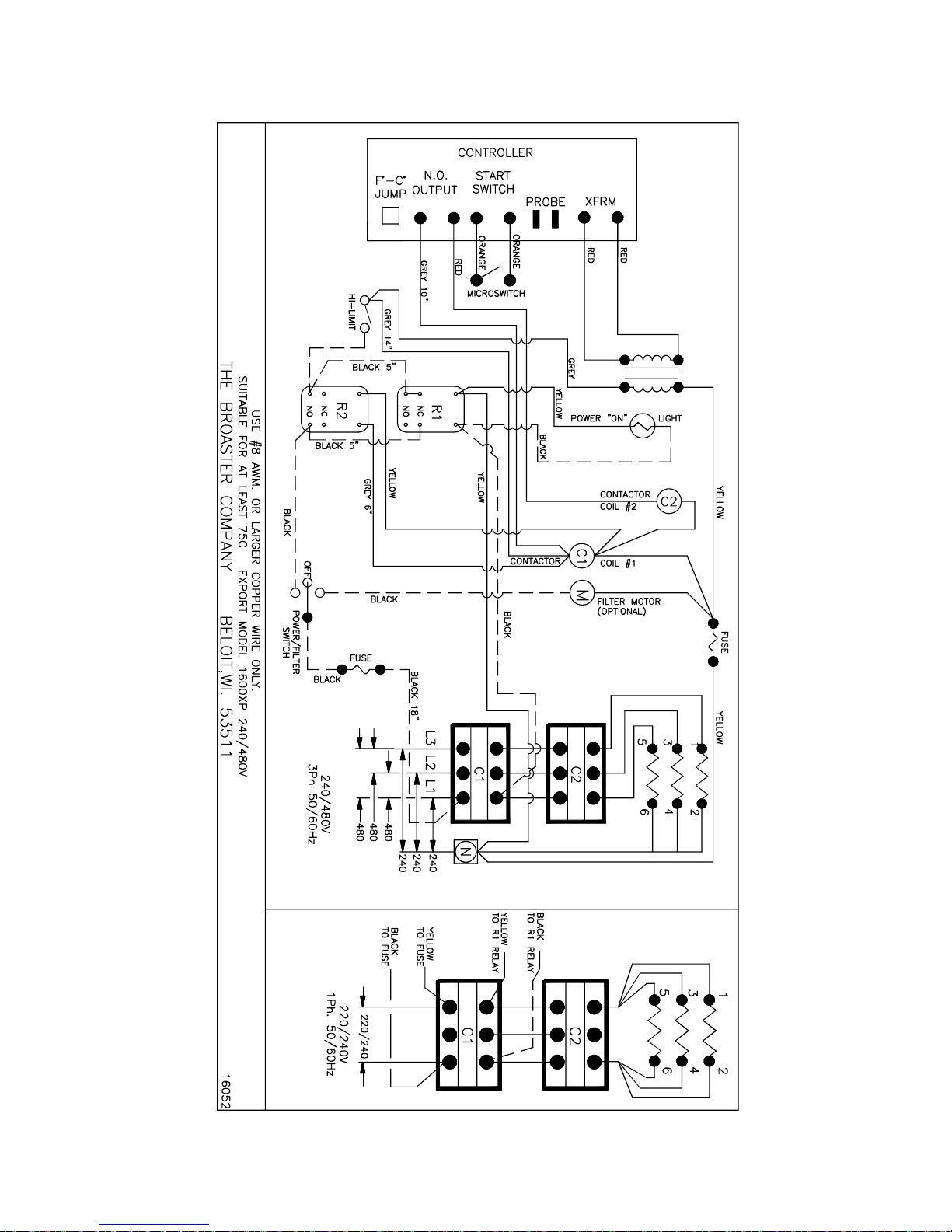
EXPORT: 1600XP Solid State 240/480VAC: Effective SE6E401231
3
6
4
1
2
5
4
6
3
1
2
5
broaster.com Manual #14678 1/99 Rev 2/14
3-22
Page 39
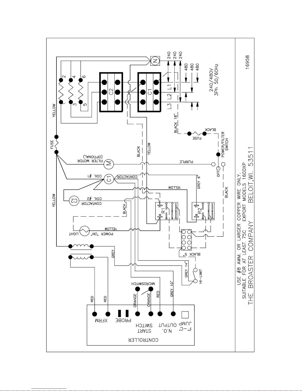
EXPORT: 1600XP Solid State 240/480VAC: Effective SE6A700013
broaster.com Manual #14678 1/99 Rev 2/14
3-23
Page 40
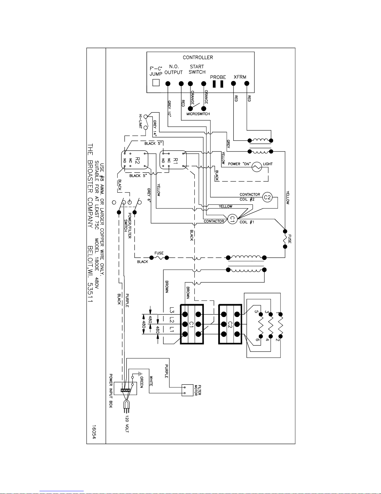
EXPORT: 1800EXP Solid State 480V: Effective January 04 (A40)
3
6
4
1
2
5
4
6
3
1
2
5
broaster.com Manual #14678 1/99 Rev 2/14
3-24
Page 41
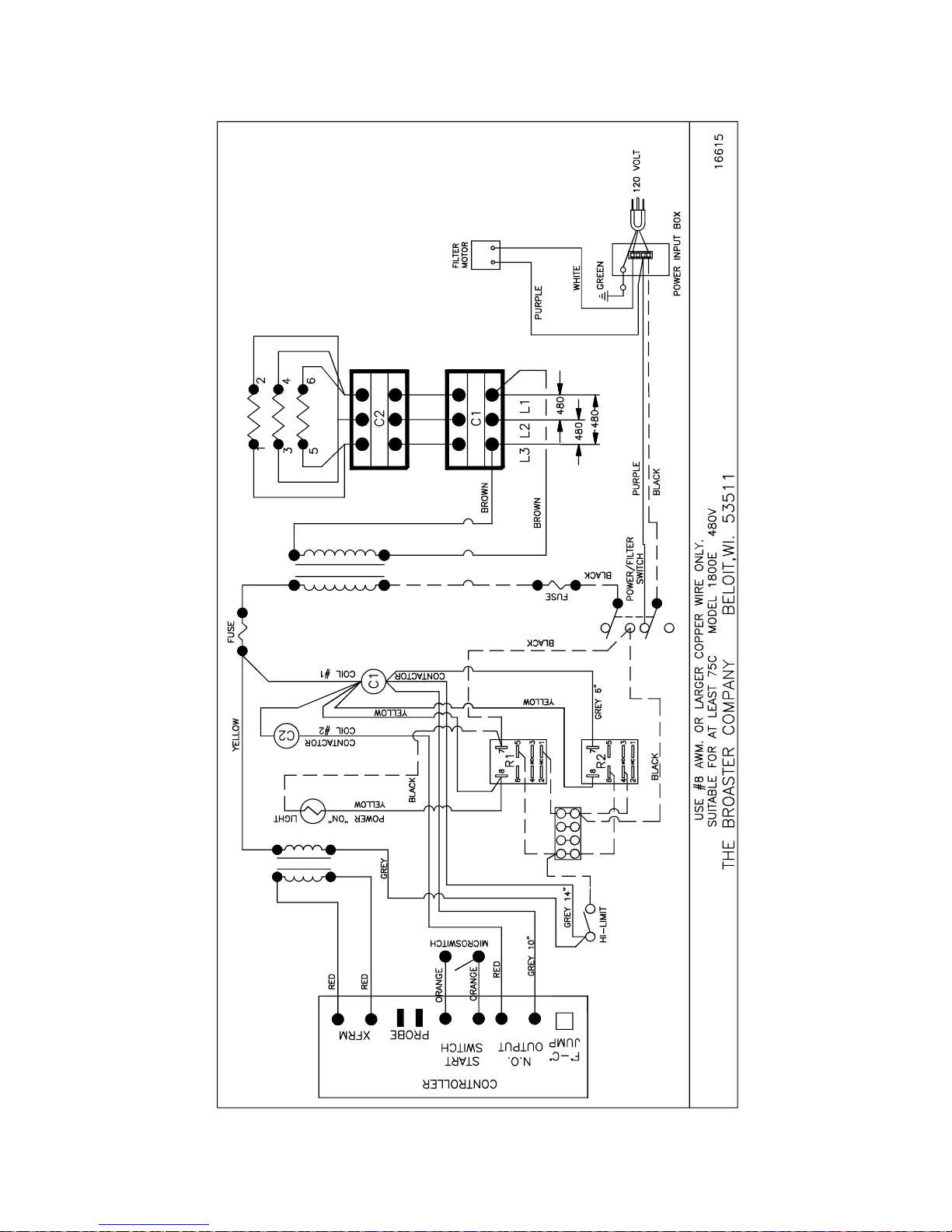
EXPORT: 1800EXP Solid State 480V: Effective January 06 (K60)
broaster.com Manual #14678 1/99 Rev 2/14
3-25
Page 42

Page 43

4 - 1800GH INSTALLATION
GENERAL REQUIREMENTS
• When installing or servicing the unit,
always check the dataplates, one
located toward the rear of the countertop and one located on the front panel.
This will make certain proper parts are
used and the correct service rendered.
DO NOT apply a voltage to this unit
other than that shown on the dataplate.
If in doubt, consult your local power
company.
• A remote circuit breaker or fuse should
be installed in main power supply
located in a path of exit and clearly identified.
• A gas shutoff valve, installed in gas supply line, should be located in a path of
exit and clearly identified.
• Keep burner area free and clear of all
combustible materials.
• DO NOT obstruct exhaust flue or open
area around bottom of unit at the front,
back and sides which would restrict the
flow of combustion and ventilation air.
• Consult a local ventilation company to
ensure an adequate air supply for all gas
fired equipment.
•EU: Installation must conform with
national & local codes of the country in
which installation is made. Gas fryers
manufactured for use in the EU are not
convertible from one gas to another.
• US & CANADA: Installation must conform with local codes, or in the absence
of local codes, with the National Fuel
Gas Code, ANSI Z223.1, Natural Gas
Installation Code, CAN/CGA-B149.1, or
the Propane Installation code, CAN/
CGA-B149.2, as applicable.
• The unit and its individual shut-off valve
must be disconnected from the gas supply piping system during any pressure
testing of that system at test pressures
in excess of 1/2psi(3.45kPa).
• The unit must be isolated from the gas
supply piping system by closing its individual manual shut-off valve during any
pressure testing of the gas supply piping
system at test pressures equal to or less
than 1/2psi(3.45kPa).
broaster.com Manual #14678 1/99 Rev 6/14b
4-1
Page 44
ELECTRICAL CHARACTERISTICS
The Model 1800GH is available for 120VAC
applied voltage, 15 amp, 60Hz, 1 phase
electrical connection in the USA and
120VAC or 220VAC applied voltage, 15
amp, 50/60Hz, 1 phase electrical connection for export applications.
• When installed, the unit must be electrically grounded in accordance with local
codes, or in the absence of local codes,
with the National Electrical Code, ANSI/
NFPA 70, or the Canadian Electrical
Code, CSA C22.2, as applicable.
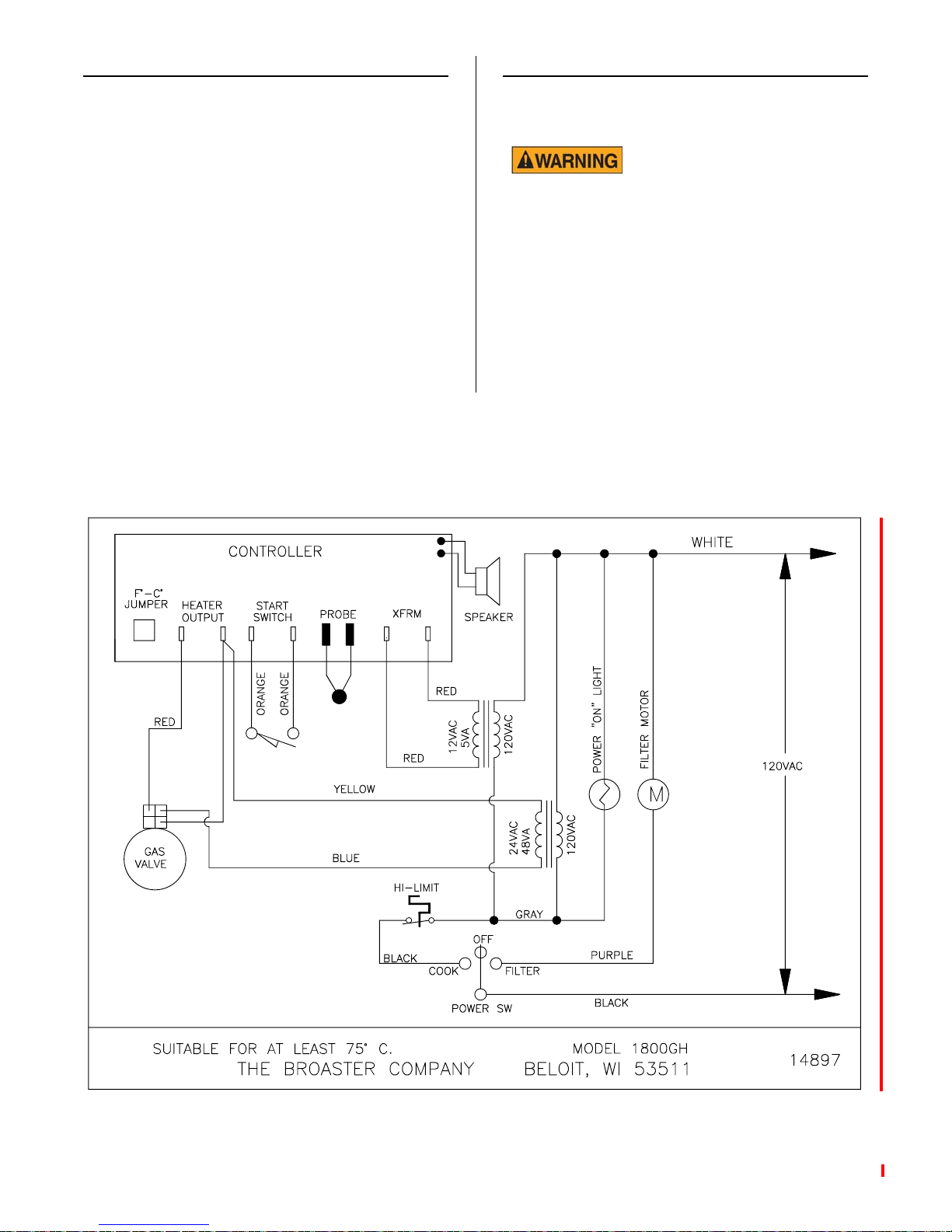
1800GH Wiring Diagram:
ELECTRICAL CONNECTIONS
• Applied voltage should match data plate
listed voltage.
Electrical Grounding
Instructions - The Model
1800GH is equipped with a three-prong
(grounding) plug for your protection against
shock hazard and should be plugged
directly into a properly grounded threeprong receptacle. DO NOT cut or remove
grounding prong from this plug.
broaster.com Manual #14678 1/99 Rev 10/14
4-2
Page 45
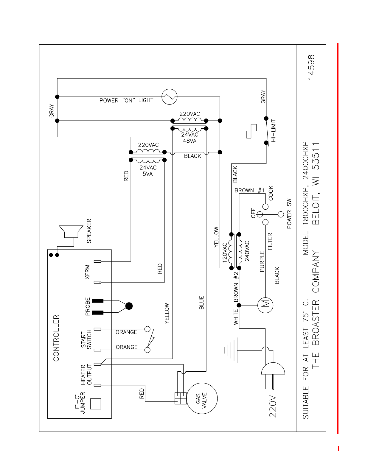
EXPORT: 1800GH Wiring Diagram:
broaster.com Manual #14678 1/99 Rev 10/14
4-3
Page 46
1
2
2
1
2
1
1800GHCE Wiring Diagram:
broaster.com Manual #14678 1/99 Rev 2/14
4-4
Page 47
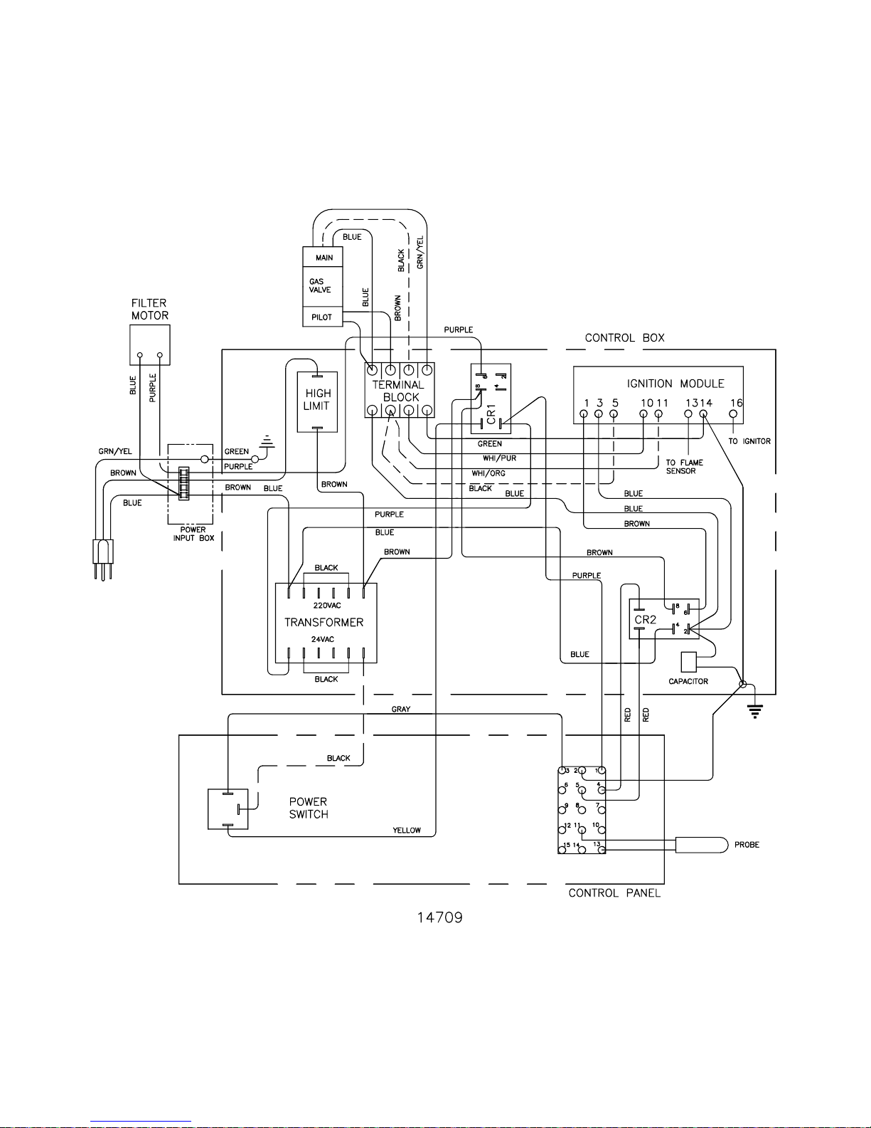
1800GHCE Wiring Diagram for the United Kingdom:
broaster.com Manual #14678 1/99 Rev 2/14
4-5
Page 48

GAS CHARACTERISTICS
Gas Conversion:
All gas units are tested using local gas supply. Your unit may or may not operate correctly on your type of gas. Therefore, the
unit should be checked and corrected if
necessary. See service manual.
DO NOT attempt to use
any other gas than that
specified on dataplate located on the front
panel.
BTU/HR Ratings:
US & CANADA
Natural Gas: 65,000
Propane: 65,000
EU
G20: 21.1 kW net
G31: 21.1 kW net
Gas Pressure and Orifices:
US & CANADA
• Contact your local Broaster Company
representative for converting from one
type of gas to another.
EU
• Units manufactured for use in the EU are
not convertible from one type of gas to
another.
High Altitude:
• For operation at elevations above 2,000
feet above sea level, gas input must be
reduced 4% for each 1,000 feet. Contact your local Broaster Company representative for correct orifice sizing.
• If adjustment of the regulator does not
deliver the correct BTU per hour or if
another type of gas is to be used, contact your local gas supply company for
correct gas pressure and orifice sizing.
Maximum gas supply line pressure:
Natural (G20) Gas: 7” wc (17.4 mbar)
Propane (G31) Gas: 14” wc (34.9 mbar)
High pressure at test fitting:
Natural (G20) Gas: 3.5”wc (8.7 mbar)
Propane (G31) Gas: 10.0”wc (24.9 mbar)
Main burner orifice size:
Natural (G20) Gas: #24 (3.9mm)
Propane (G31) Gas: #41 (2.4mm)
Pilot burner orifice size:
Natural (G21) Gas: .018 (.46mm)
Propane (G31) Gas: .011 (.27mm)
broaster.com Manual #14678 1/99 Rev 6/14
4-6
Page 49
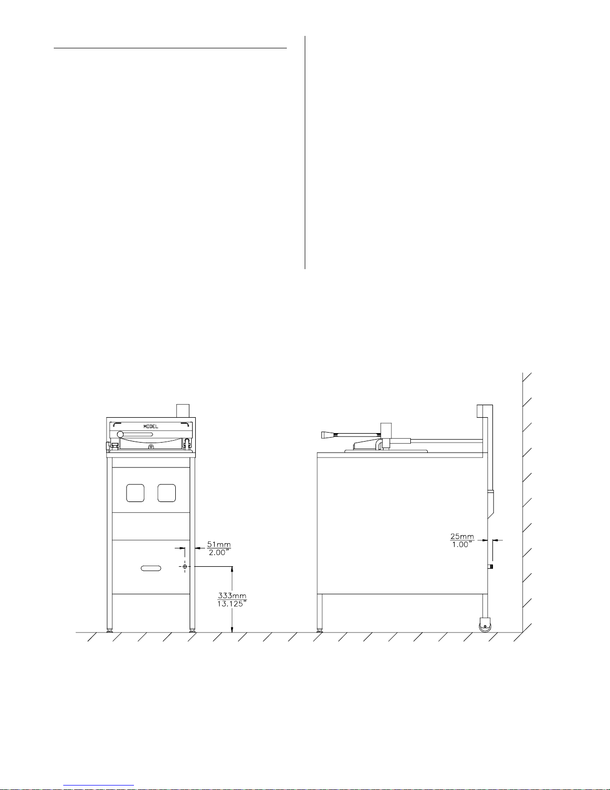
GAS PIPING
• The Model 1800GH is equipped with a
1/2” pipe for gas connection. Shipped
with each unit, for 3/4” gas connection,
is one each of the following:
• Be sure gas supply piping is of the
proper size for the BTU input. Take into
consideration all other gas appliances
which must operate from the same gas
supply. Be sure piping will not interfere
with drain pails or valves.
P/N 00743 - Bushing Hex Reducer
3/4 to 1/2
P/N 01319 - Coupling 3/4 Pipe
• Use only black steel pipe and malleable
fittings for gas connections.
• Pressure loss in the piping must not
exceed 0.3” W.C.
Unit Dimensions For Gas Hook-Up:
• A compound resistant to the action of
liquified petroleum gas should be used
on the threads of gas supply piping
joints. Check all connections and pipes
with a soap and water solution. bubbles
indicate a gas leak. DO NOT use an
open flame to check for gas leaks.
broaster.com Manual #14678 1/99 Rev 2/14
4-7
Page 50
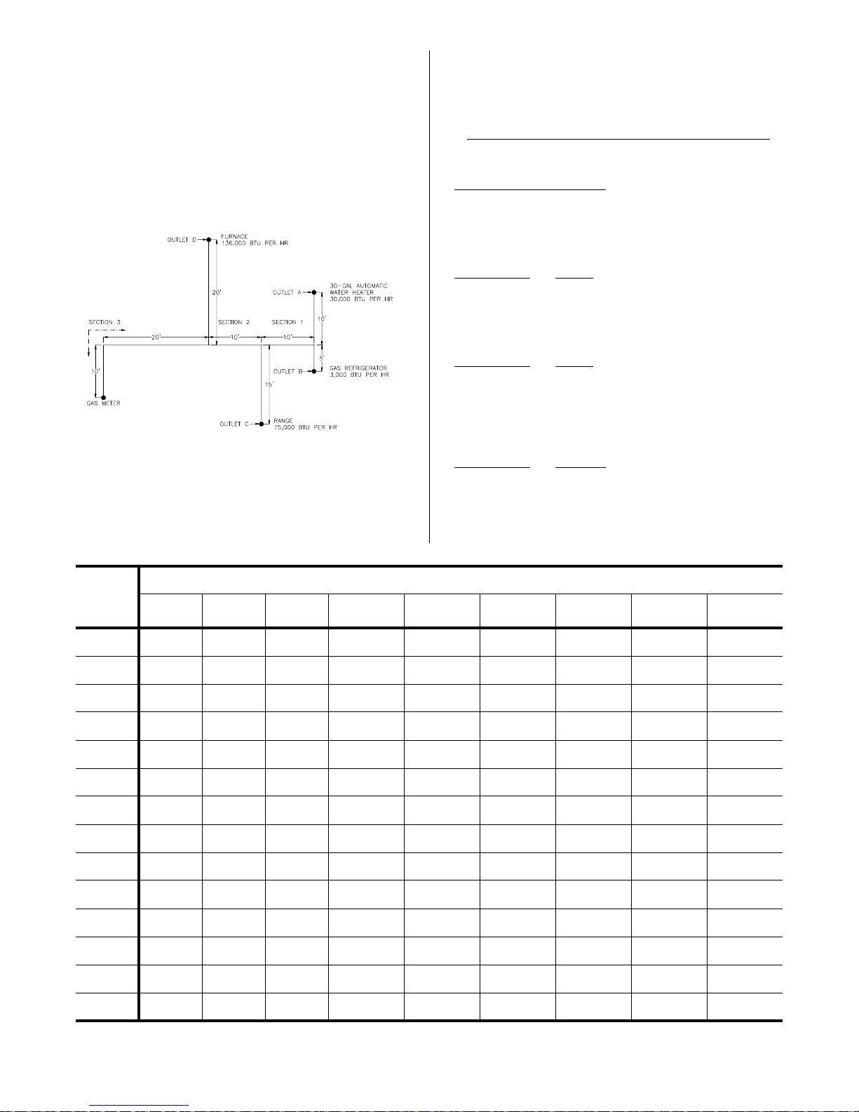
Example of Piping System Design:
Solution:
Determine the required pipe size of each
section and outlet of the piping system
shown in Solution, with a designated pressure drop of 0.50 inch water column. Gas
to be used has 0.65 specific gravity and a
heating value of 1,000 BTU per cubic foot.
Maximum capacity of pipe in cubic feet of
gas per hour (based upon a pressure drop
of 0.3 inch water column and 0.6 specific
gravity gas):
Maximum gas demand for outlet A:
consumption (rating plate input or pipe cap. if necessary)
BTU of gas
30,000 BTU per hour rating
1,000 BTU per cubic foot
= 30 cubic feet per hour (30cfh)
Maximum gas demand for outlet B:
consumption
BTU of gas
=
3,000
1,000
= 3cfh
Maximum gas demand for outlet C:
consumption
BTU of gas
=
75,00
0
= 75cfh
Maximum gas demand for outlet D:
consumption
BTU of gas
=
136,000
1,000
= 136cfh
=
Length
in
Feet
10 132 278 520 1,050 1,600 3,050 4,800 8,500 17,500
20 92 190 350 730 1,100 2,100 3,300 5,900 12,000
30 73 152 285 590 890 1,650 2,700 4,700 9,700
40 63 130 245 500 760 1,450 2,300 4,100 8,300
50 56 115 215 440 670 1,270 2,000 3,600 7,400
60 50 105 195 400 610 1,150 1,850 3,250 6,800
70 46 96 180 370 560 1,050 1,700 3,000 6,200
80 43 90 170 350 530 990 1,600 2,800 5,800
90 40 84 160 320 490 930 1,500 2,600 5,400
100 38 79 150 305 460 870 1,400 2,500 5,100
125 34 72 130 275 410 780 1,250 2,200 4,500
150 31 64 120 250 380 710 1,130 2,000 4,100
175 28 59 110 225 350 650 1,050 1,850 3,800
1/2 3/4 1 1 1/4 1 1/2 2 2 1/2 3 4
Nominal Iron Pipe Size, Inches
200 26 55 100 210 320 610 980 1,700 3,500
broaster.com Manual #14678 1/99 Rev 2/14
4-8
Page 51

5 - OPERATIONAL CHECK-OUT
See operation manual for more detailed
instructions.
COVER ASSEMBLY
DO NOT force cover open
or closed when pressure
regulating valve is closed. Damage to the
unit may occur.
1. OPEN pressure regulating valve. Be
sure pressure gauge indicates no
pressure in cooking well.
2. To OPEN cover, push down on cover
handle then rotate handle clockwise.
Slide assembly to the rear of the unit.
3. Remove basket lifter, envelope and all
other items packed in the food basket.
4. Remove food basket and packing in
bottom of cooking well.
INITIAL START UP
ELECTRIC:
DO NOT operate unit with-
out filter pan and filter pan
cover in its proper position. Filter pan cover
must be wiped clean after each filtering
cycle.
1. Clean unit as outlined in the operation
manual.
2. Make sure all controls are OFF.
3. Install cover O-ring as outlined under
COVER in CLEANING section of operation manual.
4. Fill cooking well with cooking oil. See
PRE-COOKING PREPARATIONS in
operation manual.
5. Turn circuit breaker ON or install fuse.
5. To CLOSE cover, pull assembly toward
the front and rotate handle counterclockwise.
Cover should slide easily front to back
and cover should lower and raise easily within the cooking well.
6. CLOSE pressure regulating valve handle.
Handle should slide easily from side to
side and locking pin should move in
and out over the cover.
6. Turn cook/filter switch to COOK. The
HEAT ON light will illuminate indicating
the cooking oil is being heated.
7. Set time and temperature controls.
8. Turn pressure regulating valve handle
to CLOSED. The timer will start counting down. At the end of a cook cycle,
an audible alarm will sound until pressure regulating valve handle is turned
to OPEN.
9. If CHEC appears in display, turn unit
off and back to COOK.
broaster.com Manual #14678 1/99 Rev 2/14
5-1
Page 52
GAS:
DO NOT operate unit with-
out filter pan and filter pan
cover in its proper position. Filter pan cover
must be wiped clean after each filtering
cycle.
1. Clean unit as outlined in the operation
manual.
2. Make sure all controls are OFF.
3. Install cover O-ring as outlined under
COVER in CLEANING section of operation manual.
1800GH LIGHTING INSTRUCTIONS
Start-Up:
4. Fill cooking well with cooking oil. See
PRE-COOKING PREPARATIONS in
operation manual.
5. Turn circuit breaker ON or install fuse.
6. Turn cook/filter switch to COOK. The
HEAT ON light will illuminate indicating
the cooking oil is being heated.
NOTE: Check to make sure burner is
actually lit. If not see LIGHTING
INSTRUCTIONS
7. Check flame on top of burner. It
should be all blue and settled on the
face of the burner. If it is not check to
make sure the air shutter is locked in
place.
NOTE: If it is loose see the AIR SHUTTER ADJUSTMENT procedure.
1. Turn cook/filter switch OFF.
2. See OIL LEVEL in the operation manual.
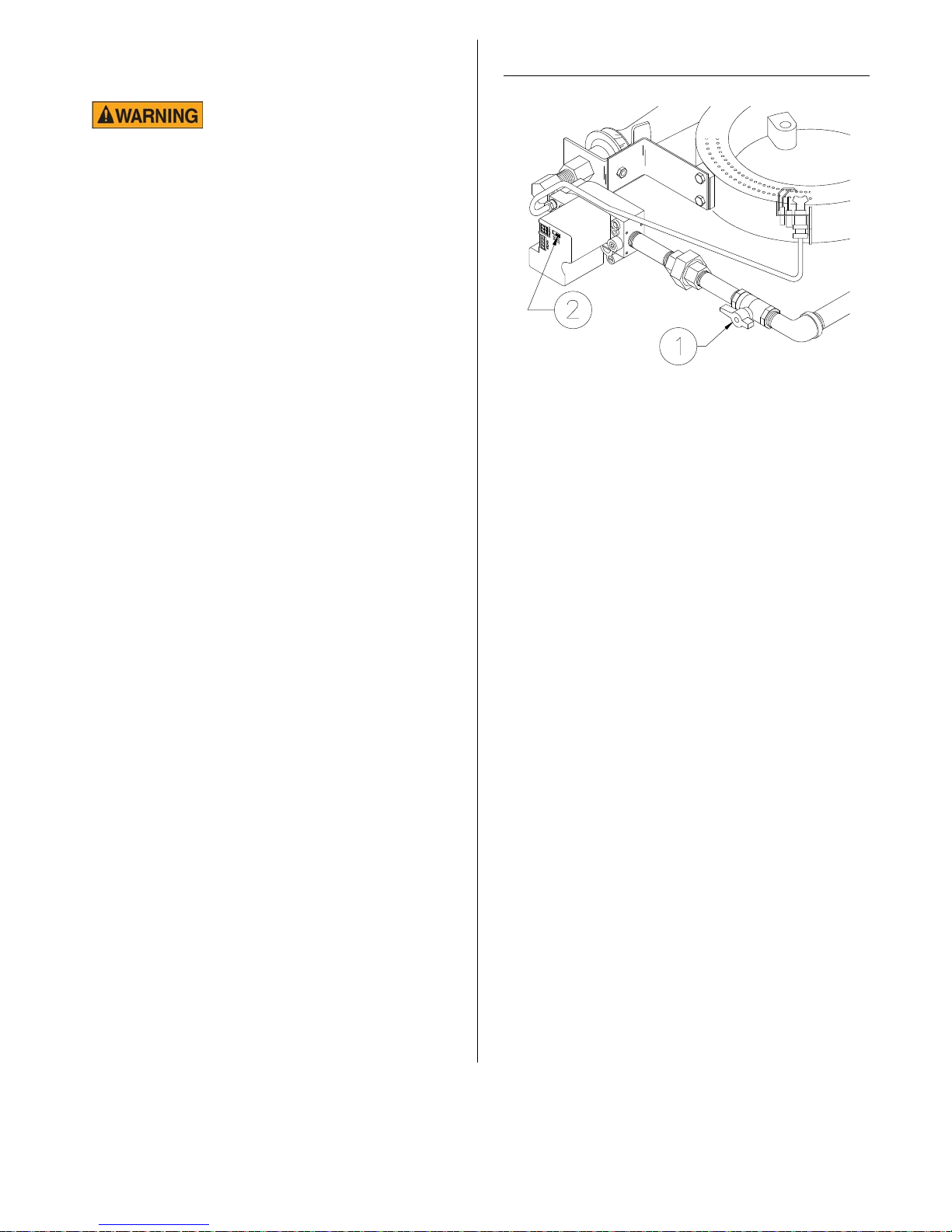
3. Turn gas shut-off valve (1) ON. Wait
five minutes before turning gas control
ON.
4. Slide switch (2) on top of gas control
to ON.
Note: The model 1800GH has an intermittent pilot burner. This type of pilot lights
when the controller calls for heat and goes
out when the controller isn’t calling for heat.
5. To light pilot and main burners, turn
cook/filter switch to COOK.
8. If CHEC appears in display, turn unit
off and back to COOK.
9. Set timer and temperature controls.
10. Turn pressure regulating valve handle
to CLOSED. The timer will start counting down. At the end of a cook cycle,
an audible alarm will sound until pressure regulating valve handle is turned
to OPEN.
broaster.com Manual #14678 1/99 Rev 2/14
5-2
Page 53
Shut Down:
Adjustment:
1. Turn cook/filter switch OFF.
2. Turn gas control switch (2) OFF.
3. Turn gas shut-off (1) valve OFF.
AIR SHUTTER ADJUSTMENT
Maintains air/gas mixture for good combustion. Start with a 1/4” gap after installing a
new gas valve or piping.
Adjustment will be necessary if main burner
flame is mostly orange or yellow. If flame is
out of adjustment, check combustion
chamber and flue for soot build-up.
If soot is present, DO NOT
operate unit and call Service Technician. Soot is black and powdery
to the touch. See COMBUSTION CHAMBER.
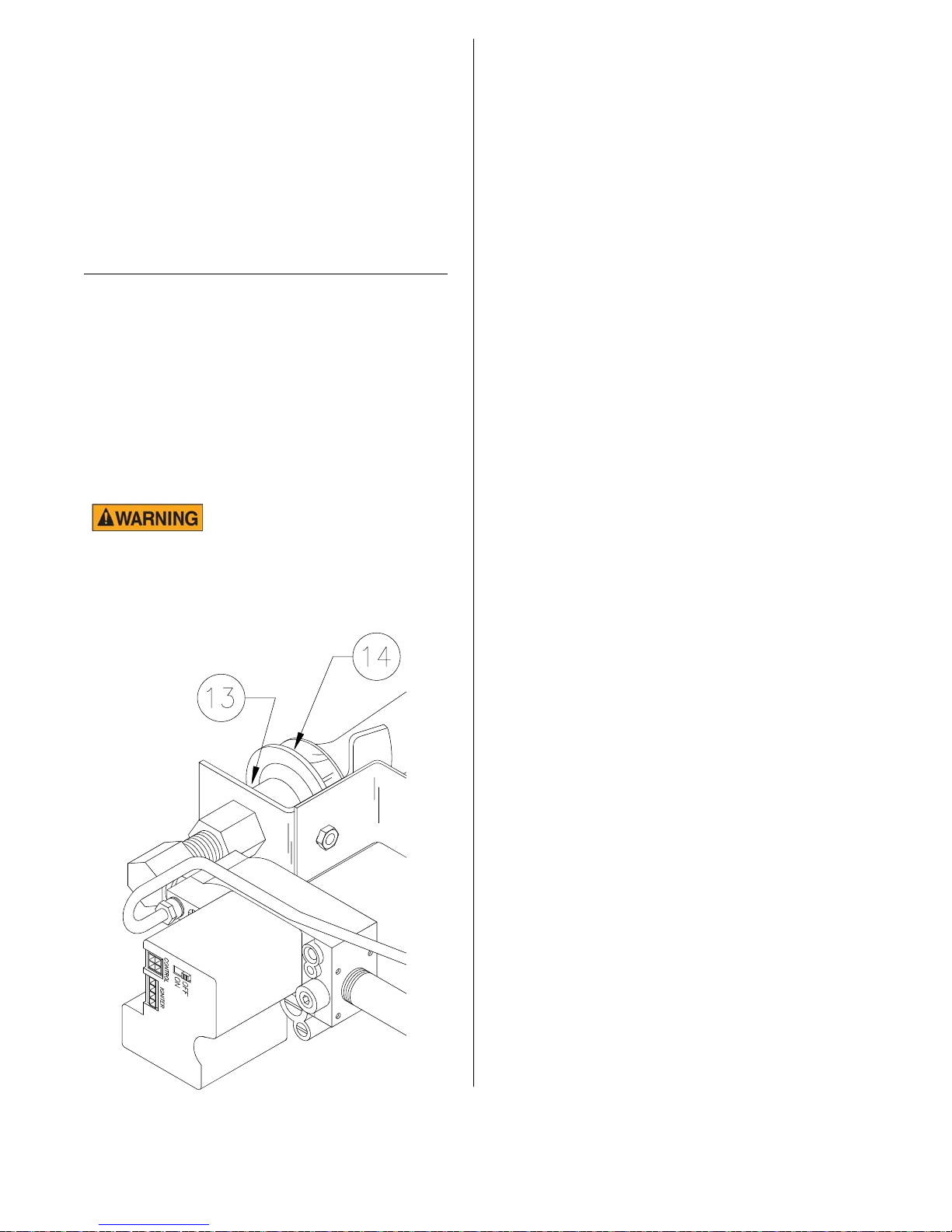
1. Loosen locknut (13) which locks air
shutter.
2. Screw shutter (14) in or out to obtain a
blue flame. Flame should start burning slightly above main burner.
3. Tighten locknut.
broaster.com Manual #14678 1/99 Rev 2/14
5-3
Page 54

Page 55

Page 56

The Broaster Company
2855 Cranston Road, Beloit, WI 53511-3991
608/365-0193
broaster.com
 Loading...