

Page 1

ROOMSIDE SERIES
Decorative Fan-Light
Ventilador con luz decorativo
Model number:
Número de modelo:
INSTALLATION AND
USE & CARE INSTRUCTIONS
INSTRUCCIONES DE INSTALACIÓN,
Español - Consulte la página 9
AER110SLW
AERN110SLW
USO Y CUIDADO
English - See page 2
© 2019 Broan-NuTone LLC
1102077B
Page 2
Register this product at www.nutone.com/register. For Warranty Statement, or to order Service Parts: go
to www.broan.com or www.nutone.com and type the model number in the “Model Search” field.
Broan, 926 W. State Street, Hartford, WI 53027 800-558-1711 888-336-3948
Installer: Leave this manual with the homeowner.
READ AND SAVE THESE INSTRUCTIONS
WARNING
To reduce the risk of fire, electric
shock, or injury to persons, observe the
following:
• Use this unit only in the manner
intended by the manufacturer. If
you have questions, contact the
manufacturer at the address or
telephone number listed in the warranty.
• Before servicing or cleaning unit,
switch power off at service panel and
lock the service disconnecting means
to prevent power from being switched
on accidentally. When the service
disconnecting means cannot be locked,
securely fasten a prominent warning
device, such as a tag, to the service
panel.
• Installation work and electrical wiring
must be done by a qualified person(s)
in accordance with all applicable codes
and standards, including fire-rated
construction codes and standards.
• Sufficient air is needed for proper
combustion and exhausting of
gases through the flue (chimney) of
fuel burning equipment to prevent
backdrafting. Follow the heating
equipment manufacturer’s guideline
and safety standards such as those
published by the National Fire
Protection Association (NFPA), and
the American Society for Heating,
Refrigeration and Air Conditioning
Engineers (ASHRAE), and the local
code authorities.
• When cutting or drilling into wall or
ceiling, do not damage electrical wiring
and other hidden utilities.
• Ducted fans must always be vented to
the outdoors.
• This unit must be grounded.
CAUTION
• For general ventilating use only. Do not
use to exhaust hazardous or explosive
materials and vapors.
• For installation in flat ceilings only.
• To avoid motor bearing damage and
noisy and/or unbalanced impellers, keep
drywall spray, construction dust, etc. off
power unit.
• Please read specification label on
product for further information and
requirements.
INSTALLATION AND USE & CARE INSTRUCTIONS
SAFETY
2
Page 3
CLEANING & MAINTENANCE
For quiet and efficient operation, long life, and attractive
appearance - remove grille and vacuum interior of unit
with the dusting brush attachment.
The motor is permanently lubricated and never needs
oiling. If the motor bearings are making excessive or
unusual noises, replace the blower assembly (includes
motor and impeller).
OPERATION
SENSOR CLEANING
The humidity sensor is mounted in the control housing. The
sensor will operate most reliably when cleaned occasionally
as follows:
1. Disconnect power at service entrance.
2. Remove the grille. Use a dry dustcloth, clean toothbrush,
or lightly vacuum to clean sensor and grille. DO NOT
USE ABRASIVE CLOTH, STEEL WOOL PADS, OR
SCOURING POWDERS.
3. DO NOT USE cleaning sprays, solvents, or water on or
near the sensor!
The humidity control and fan can be operated
separately. Use a 1- or 2-function wall control. Do
not use a dimmer switch to operate the humidity
control.
SENSOR OPERATION
This humidity-sensing fan uses a sophisticated
humidity sensor that responds to: (a) rapid to
moderate increases in humidity or (b) humidity above
a set-point. The humidity sensor may occasionally
turn the fan ON when environmental conditions
change.
MANUAL ON WITH TIMED OFF
This humidity sensing fan has an additional operation
feature. For odor or vapor control, the fan can be
energized by cycling the power switch. Once the fan
has been energized in this manner, it will remain on
for the set timer period.
To manually energize the fan:
1. If fan power switch is already ON, proceed to
Step 2; otherwise, turn power switch ON for more
than 1 second.
2. Turn fan power switch OFF for less than 1
second.
3. Turn fan power switch back ON and fan will turn
ON.
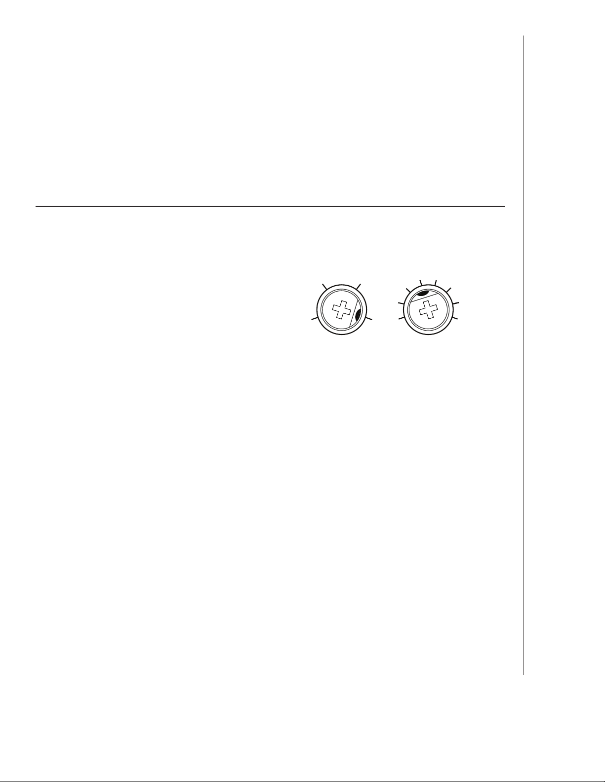
%HUMIDITY MINUTES
60
50
% HUMIDITY ADJUSTMENT
%HUMIDITY has been factory set at 80% for most
shower applications. If fan is not responding to changing
humidity conditions, adjust toward 50%. If fan is
responding too often to changing humidity conditions,
adjust toward 80%. If fan is still responding too often at
80%, contact Broan Technical Support.
To adjust the %HUMIDITY:
1. Turn power off at electrical service panel.
2. Use a small screwdriver to carefully rotate
%HUMIDITY control to desired level.
3. Turn power on.
4. Repeat above steps if necessary.
MINUTES ADJUSTMENT (TIMER)
This humidity-sensing fan has a timer that controls how
long the fan remains on after (a) rise in humidity and
(b) humidity level are both below the user-adjustable
%HUMIDITY setting, or after being energized by cycling
power switch.
To adjust the timer:
1. Disconnect power at electrical service panel.
2. Use a small screwdriver to carefully rotate MINUTES
control to increase or decrease time.
3. Turn power on.
4. Repeat above steps if necessary.
70
80
Factory settings shown.
15
10
5
20 30
40
50
60
INSTALLATION AND USE & CARE INSTRUCTIONS
OPERATION
3
Page 4
ALL INSTALLATIONS
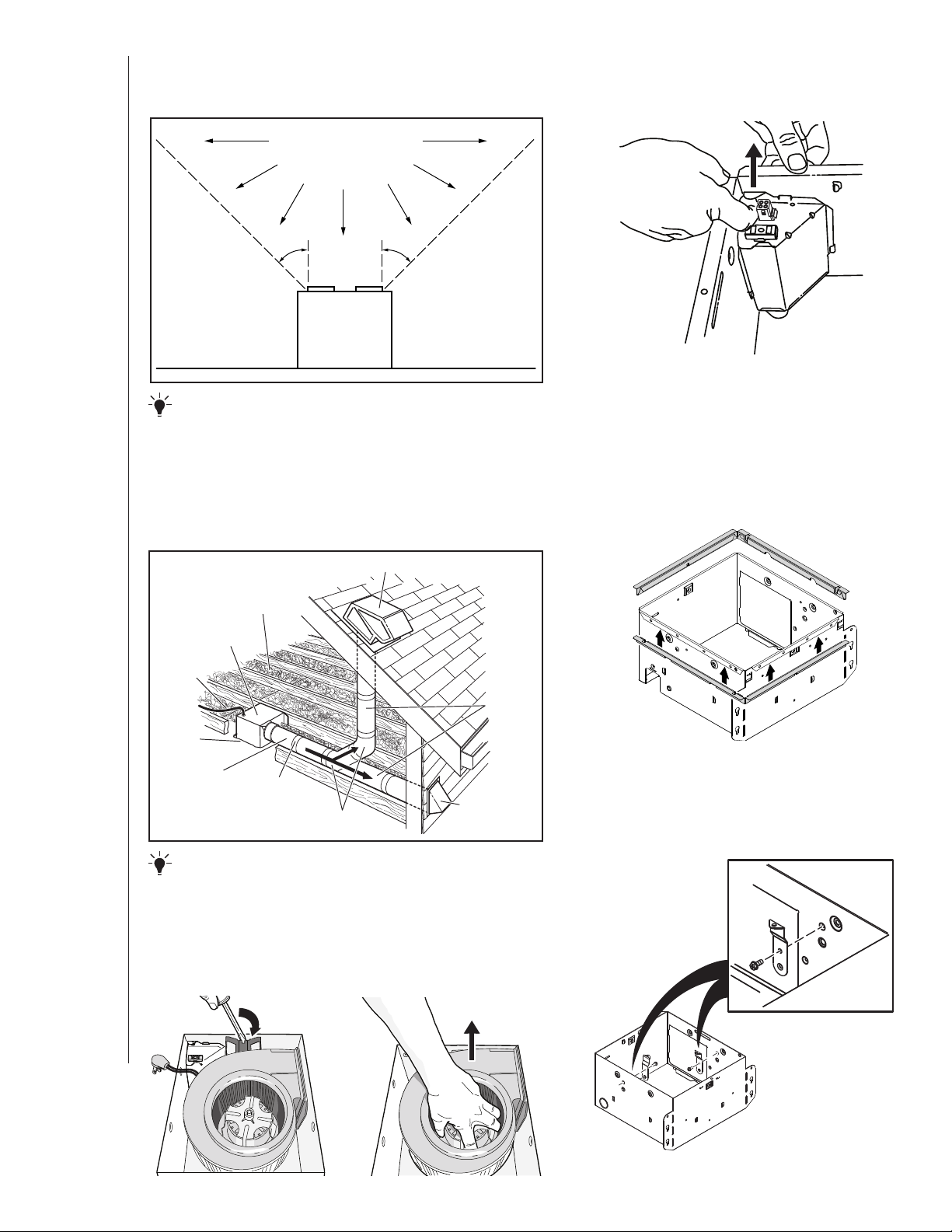
Start here.
COOKING AREA
Do not install above or
inside this area.
2. Remove wiring panel from
fan housing.
NOT FOR USE IN
A COOKING AREA.
45
o
Cooking
Equipment
45
o
Floor
IMPORTANT - The ducting from this fan to the outside
of the building has a strong effect on the air flow, noise and
energy use of the fan. Use the shortest, straightest duct routing
possible for best performance, and avoid installing the fan with
smaller ducts than recommended. Insulation around the ducts
can reduce energy loss and inhibit mold growth. Fans installed
with existing ducts may not achieve their rated airflow.
ROOF CAP * (with built-in damper)
INSULATION
(Place around and
over fan housing.)
FAN
HOUSING
POWER
CABLE
*
Keep duct
runs short.
Seal gaps
around
housing.
4-IN. ROUND
DUCT
*
Purchase separately.
*
OPTION -
Seal duct joints
with tape.
To mount housing anywhere between ceiling framing:
OR
4-IN. ROUND
ELBOWS
WALL CAP
(with built-in
*
*
damper)
Use optional Hanger Bar Kit (sold separately from local distributors or
website). Follow mounting instructions included with kit.
3. A pair of flanges may be
attached to housing if
desired or required.
Snap both flange pieces under rolled-over edge
of housing (all four sides).
4. Attach grille brackets to
housing.
INSTALLATION AND USE & CARE INSTRUCTIONS
4
1. Remove blower and all packing
material from fan housing.
INSTALLATION
Page 5

NEW CONSTRUCTION
For Retrofit Installation - Skip to Page 6.
5. Attach damper/duct connector
to fan housing.
Push connector through opening from inside of housing.
Engage tabs and secure with screw from parts bag.
TABS
7. Connect 4-in. round duct.
8. Connect wiring.
Connect power cable to housing with appropriate
UL approved connector. Make wiring connections as
shown in “Wiring Diagrams” section. Re-install wiring
panel and secure with screw from parts bag.
6. Mount housing to ceiling
structure.
Make sure bottom of housing will be flush with finished
ceiling.
For proper location using ½” ceiling material: Bend out
housing tabs to fit against bottom of structure.
Secure housing through mounting ears with
appropriate fasteners.
If mounting housing to I-joist, use wood blocking as
shown.
I-JOIST
WOOD
BLOCKING
CAUTION
• DO NOT TOUCH THE HUMIDITYSENSING CIRCUIT BOARD.
Electrostatic discharge may damage
the circuit board.
INSTALLATION AND USE & CARE INSTRUCTIONS
INSTALLATION
HOUSING TABS
5
Page 6
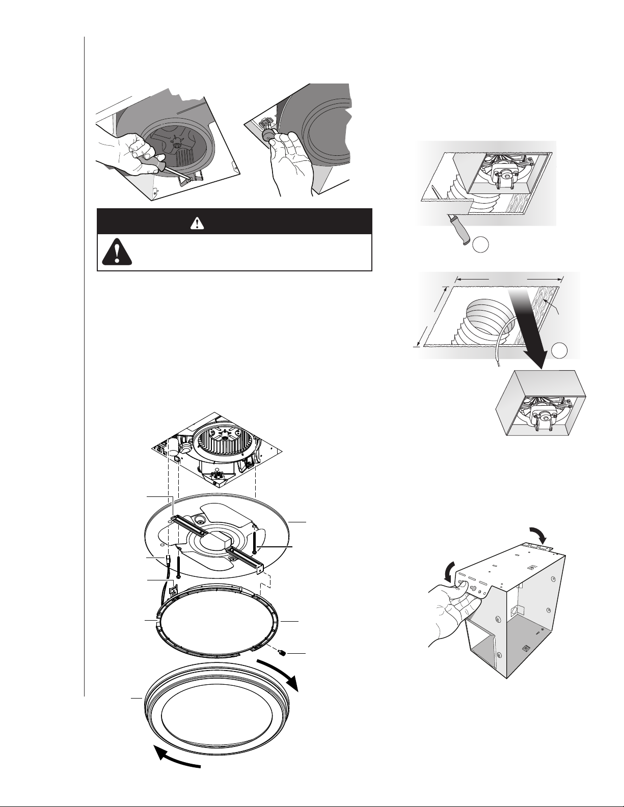
9. Install blower.
Re-install blower. Secure blower with 2 screws from parts bag and plug
blower into black receptacle.
CAUTION
RETROFIT
5. Remove old fan.
Enlarge ceiling opening (if necessary)
to 9¾” parallel to joist) by 10½”
(perpendicular to joist). Leave ductwork
and wiring in place.
• Make sure that the wiring inside of the housing
does not interfere with re-installation of the blower.
10. Finish ceiling, then install grille.
Attach MOUNTING PLATE to housing with (2) SCREWS.
Connect LIGHT PANEL PLUG to receptacle in corner of housing.
Place LIGHT PANEL SLOT over HOOK on MOUNTING PLATE.
Swing opposite side of LIGHT PANEL up to MOUNTING PLATE and
secure with ATTACHMENT SCREW.
Line up GRILLE FRAME with (3) LIGHT PANEL OPENINGS and
rotate GRILLE FRAME clockwise to secure it to LIGHT PANEL.
HOOK
MOUNTING
PLATE
LIGHT PANEL
PLUG
SLOT
MOUNTING
PLATE
ATTACHMENT
SCREW (2)
1
10½-in.
9¾-in.
JOIST
2
6. Fold mounting ears flat
against housing.
INSTALLATION AND USE & CARE INSTRUCTIONS
6
OPENING (3)
INSTALLATION
GRILLE
FRAME
LIGHT
PANEL
LIGHT
PANEL
ATTACHMENT
SCREW
Page 7
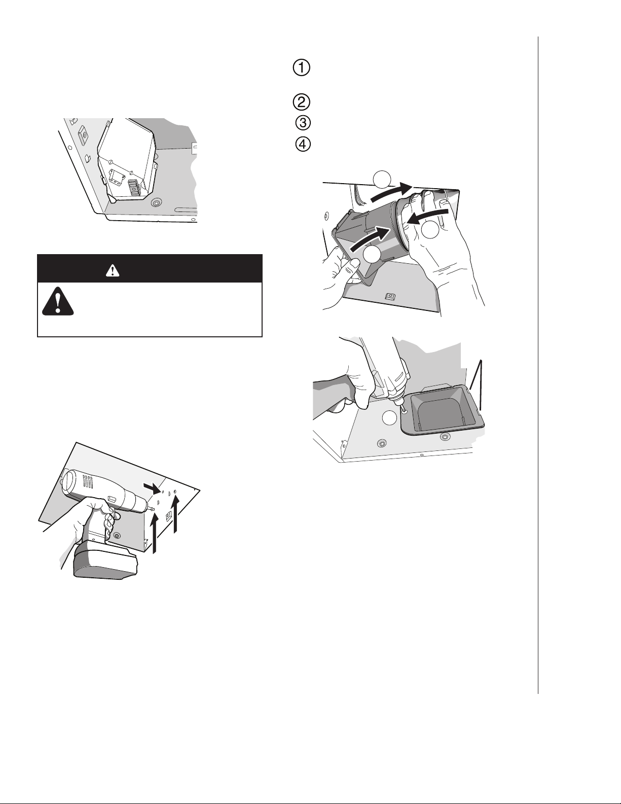
7. Connect wiring.
Connect power cable to housing with appropriate UL
approved connector. Make wiring connections as shown
in “Wiring Diagrams” section. Re-install wiring panel and
secure with screw from parts bag.
CAUTION
• DO NOT TOUCH THE HUMIDITYSENSING CIRCUIT BOARD.
Electrostatic discharge may damage
the circuit board.
9. Connect 4-in. round duct.
Pull existing ducting through housing discharge
opening.
Attach and tape ducting to duct connector.
Push connector/ducting back through opening.
Engage tabs and secure with screw from parts
bag.
3
1
2
8. Mount fan to ceiling structure.
Mount housing to ceiling structure with standard
drywall or wood screws in locations shown.
Center hole optional.
*
TABS
4
INSTALLATION AND USE & CARE INSTRUCTIONS
Install blower. Finish ceiling, then
install grille.
See Steps 9 & 10 on Page 6.
INSTALLATION
7
Page 8
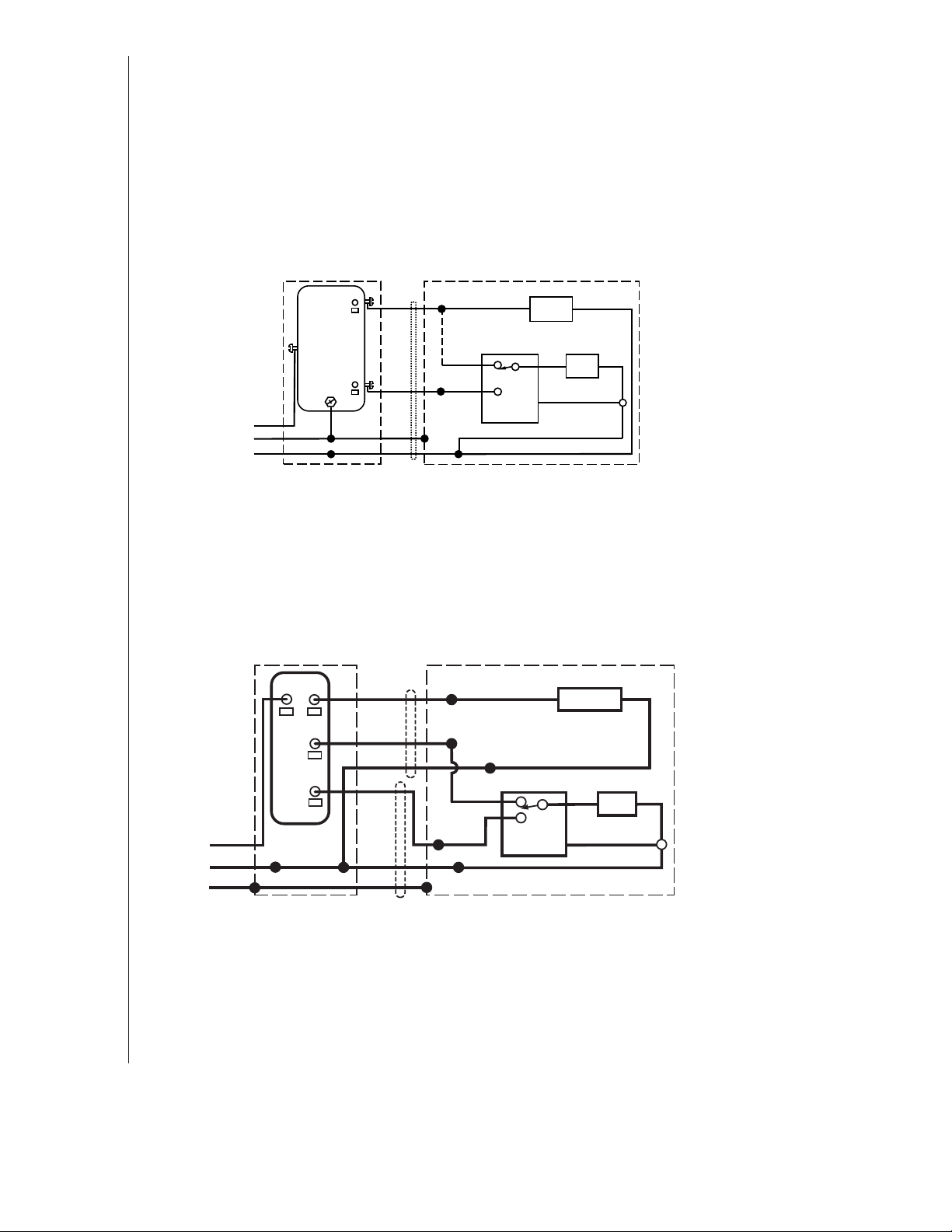
WIRING DIAGRAMS
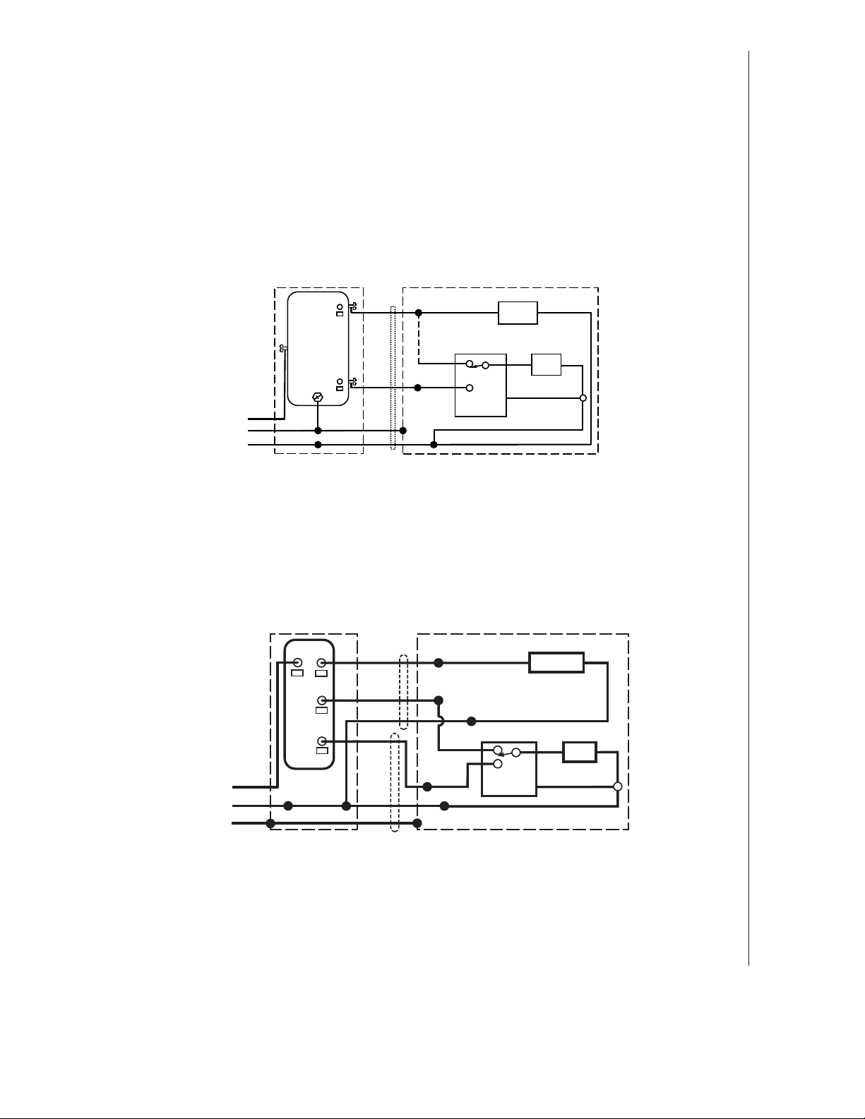
WIRING OPTION #1
• When first switch (1) is ON, fan will operate automatically, based on room humidity conditions.
• Turn fan ON immediately for the set timer period (to control odors), by cycling first switch.
• Use second switch (2) to turn light ON/OFF.
• With optional connection shown, fan will always be ON when light is ON.
2-FUNCTION CONTROL
(PURCHASE SEPARATELY)
(2)
LIGHT
(ON/OFF)
(1)
FAN
(AUTO/OFF)
BLK
120
VAC
GRD
LINE
WHT
IN
RED
COM
GRD
SWITCH UNIT
BLK
GRD
(Optional)
GREY
BRN
BLK
HUMIDITY
CONTROL
LIGHT
BLK
FAN
WHT
WHT
WHTWHT
WHT
WIRING OPTION #2
• When first switch (1) is ON, fan will operate automatically based on room humidity conditions.
• Turn fan ON immediately (to control odors) by using second switch (2).
• Use third switch (3) to turn light ON/OFF.
3-FUNCTION CONTROL
(PURCHASE SEPARATELY)
(3)
LIGHT
(ON/OFF)
(2)
FAN
(ON/OFF)
(1)
FAN AUTO
(AUTO/OFF)
BLK
120
WHT
VAC
LINE
GRD
IN
COM
SWITCH
BLK
RED
WHT
BLK
WHT
GRD
BRN
GREY
BLK
HUMIDITY
CONTROL
WHT
UNIT
LIGHT
BLK
FAN
WHT
WHT
WHT
INSTALLATION AND USE & CARE INSTRUCTIONS
8
INSTALLATION
Page 9
Registre este producto en www.nutone.com/register. Para ver la declaración de garantía o para ordenar piezas de
repuesto: visite www.broan.com o www.nutone.com y escriba el número de modelo en el campo “Model Search”
(Buscar modelo).
Broan, 926 W. State Street, Hartford, WI 53027 800-558-1711 888-336-3948
Aviso al instalador: Deje este manual con el dueño de la casa.
LEA Y CONSERVE ESTAS INSTRUCCIONES
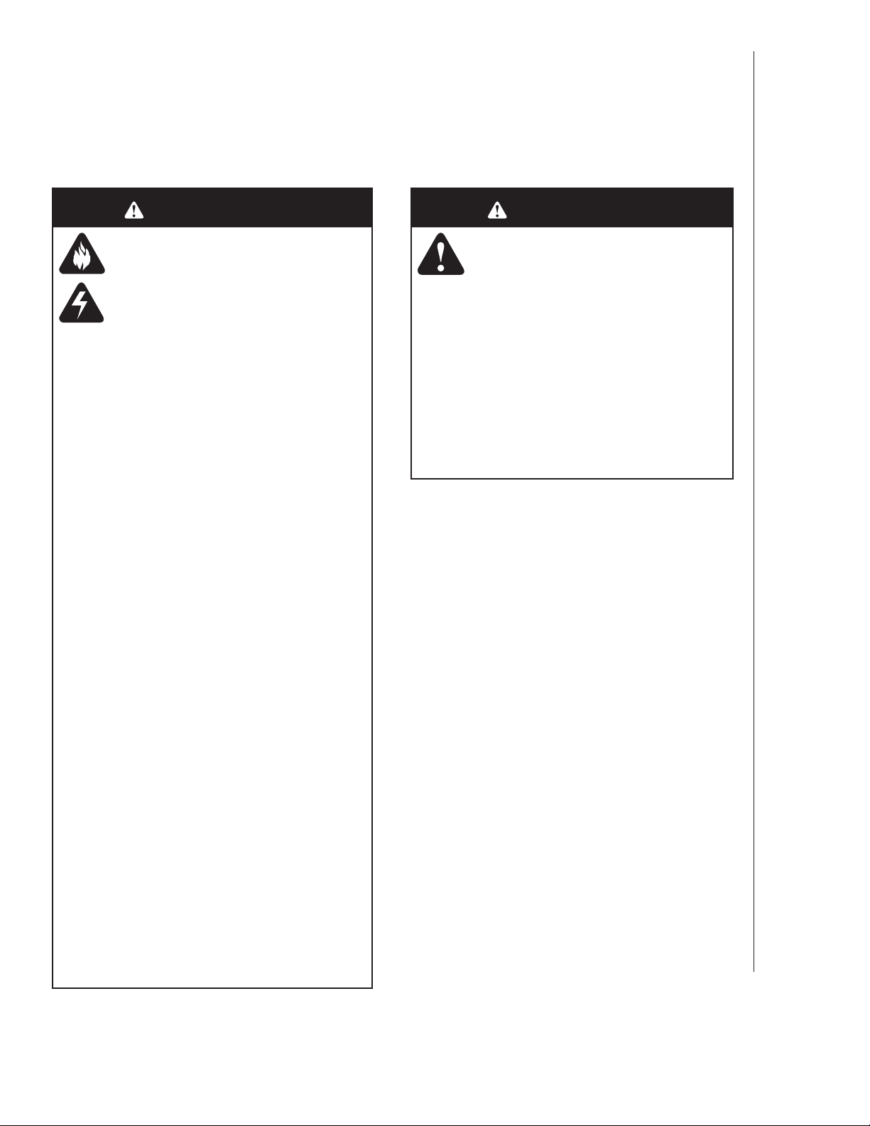
ADVERTENCIA
Para reducir el riesgo de incendios,
descargas eléctricas o lesiones
personales, observe las siguientes
precauciones:
• Use la unidad solo de la manera indicada
por el fabricante. Si tiene preguntas,
comuníquese con el fabricante a la dirección
o al número telefónico que se incluye en la
garantía.
• Antes de dar servicio a la unidad o de
limpiarla, interrumpa el suministro eléctrico
en el panel de servicio y bloquee los medios
de desconexión del servicio para evitar que
la electricidad se reanude accidentalmente.
Cuando no sea posible bloquear los medios
de desconexión del servicio, fije firmemente
una señal de advertencia (como una
etiqueta) en un lugar visible del panel de
servicio.
• El trabajo de instalación y el cableado
eléctrico deben estar a cargo de personal
capacitado, de acuerdo con todos los
códigos y normas correspondientes, que
incluyen los códigos y las normas de
construcción específicos sobre protección
contra incendios.
• Es necesario suficiente aire para que
se lleve a cabo una combustión y una
extracción adecuadas de los gases a través
del tubo de humos (chimenea) del equipo
quemador de combustible, con el fin de
evitar el contratiro. Siga las directrices y
las normas de seguridad del fabricante del
equipo de calefacción, como las publicadas
por la Asociación Nacional de Protección
contra Incendios (National Fire Protection
Association, NFPA), la Sociedad Americana
de Ingenieros de Calefacción, Refrigeración
y Aire Acondicionado (American Society for
Heating, Refrigeration and Air Conditioning
Engineers, ASHRAE) y las autoridades de
los códigos locales.
• Al cortar o perforar a través de la pared o
del cielo raso, tenga cuidado de no dañar el
cableado eléctrico ni otros servicios ocultos.
• Los ventiladores con conductos siempre
deben ventearse hacia el exterior.
• Esta unidad debe estar conectada a tierra.
PRECAUCIÓN
• Solo para usarse como medio de ventilación
general. No debe usarse para la extracción
de materiales y vapores peligrosos o
explosivos.
• Para instalarse en cielos rasos planos
solamente.
• Para evitar daños a los cojinetes del motor
y rotores ruidosos o desbalanceados,
mantenga la unidad de potencia protegida
contra rociados de yeso, polvos de
construcción, etc.
• Lea la etiqueta de especificaciones del
producto para ver información y requisitos
adicionales.
INSTRUCCIONES DE INSTALACIÓN, USO Y CUIDADO
SEGURIDAD
9
Page 10
LIMPIEZA Y MANTENIMIENTO
Para lograr un funcionamiento silencioso y eficiente,
una larga vida y la apariencia atractiva del producto,
retire la rejilla y aspire el interior de la unidad con el
accesorio del cepillo para sacudir polvo.
El motor está permanentemente lubricado y nunca
necesitará ponerle aceite. Si los cojinetes del motor
están haciendo ruido excesivo o inusual, reemplace el
conjunto del ventilador (incluye el motor y el impulsor).
FUNCIONAMIENTO
LIMPIEZA DEL SENSOR
El sensor de humedad está montado en la cubierta de
control. El funcionamiento del sensor será más confiable
si se limpia ocasionalmente. Para ello, haga lo siguiente:
1. Desconecte la energía en la entrada de servicio.
2. Quite la rejilla. Limpie el sensor y la rejilla con
un paño sacudidor seco o un cepillo de dientes
limpio, o aspírelos ligeramente. NO USE PAÑOS
ABRASIVOS, ALMOHADILLAS DE LANA DE
ACERO NI POLVOS ABRASIVOS.
3. ¡NO USE sprays limpiadores, solventes ni agua en el
sensor o cerca del mismo!
INSTRUCCIONES DE INSTALACIÓN, USO Y CUIDADO
FUNCIONAMIENTO
10
El control de humedad y el ventilador pueden
funcionar por separado. Utilice un control de pared de
1 o 2 funciones. No utilice un reductor de intensidad
para hacer funcionar el control de humedad.
OPERACIÓN DEL SENSOR
Este ventilador con sensor de humedad utiliza un
avanzado sensor de humedad que responde a:
(a) aumentos de rápidos a moderados en humedad
o (b) humedad por arriba de un punto establecido.
Ocasionalmente el sensor de humedad puede
encender el ventilador cuando cambian las
condiciones ambientales.
MANUAL CON TIEMPO DE APAGADO
Este ventilador con sensor de humedad tiene una
característica adicional de operación. Para el control
del olor o del vapor, se puede energizar el ventilador
al “ciclar” (apagar y encender) el interruptor de
alimentación. Una vez que se energice el ventilador
de esta manera, se mantendrá encendido durante el
periodo establecido en el temporizador.
Para energizar manualmente el ventilador:
1. Si el interruptor de alimentación ya está
encendido, proceda con el paso 2; de otra
manera, encienda el interruptor de alimentación
durante más de 1 segundo.
2. Apague el interruptor de alimentación por menos
de 1 segundo.
3. Vuelva a encender el interruptor de alimentación;
el ventilador se encenderá.
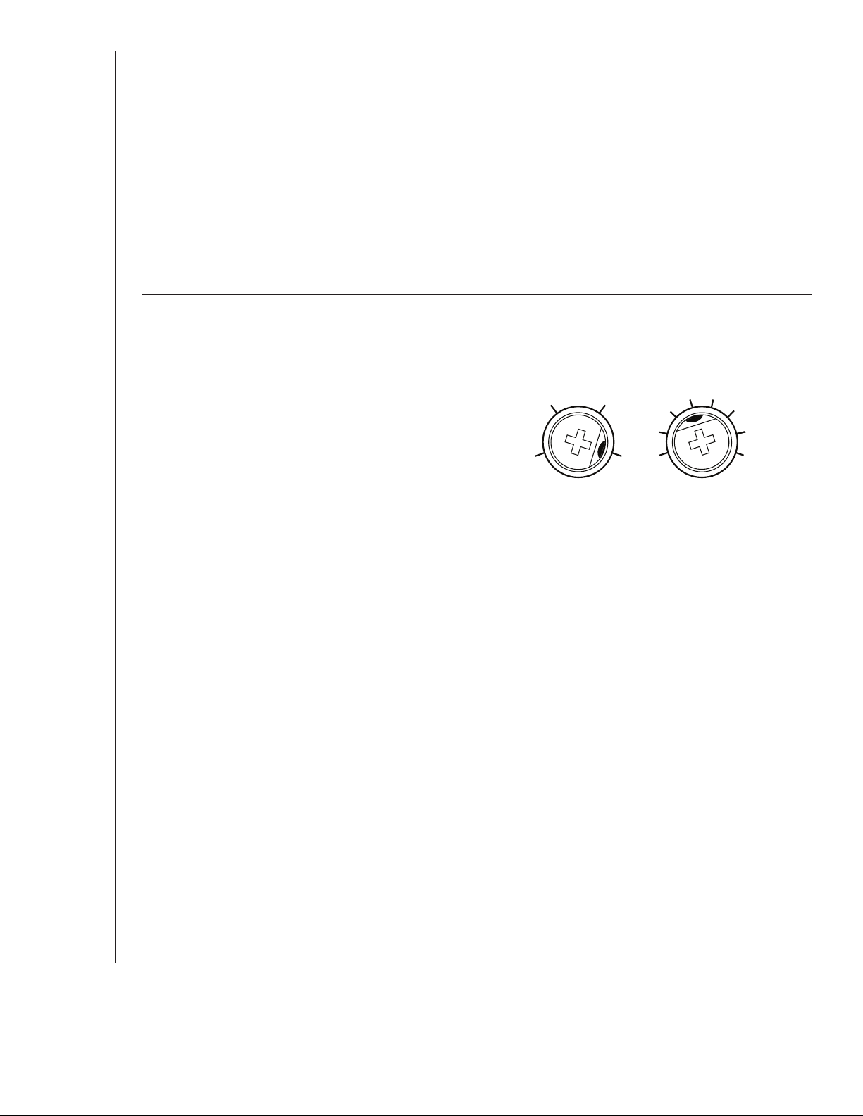
%HUMIDITY MINUTES
60
50
Se muestran los ajustes de fábrica.
% DE AJUSTE DE LA HUMEDAD
El % de HUMEDAD viene ajustado de fábrica al 80%
para la mayoría de las aplicaciones de regadera. Si el
ventilador no responde a las condiciones cambiantes
de humedad, ajuste al 50%. Si el ventilador responde
con demasiada frecuencia a las condiciones cambiantes
de humedad, ajuste al 80%. Si el ventilador sigue
respondiendo con demasiada frecuencia al 80%,
comuníquese con el equipo de apoyo técnico de Broan.
Para ajustar el porcentaje de humedad “%HUMIDITY”:
1. Apague la energía en el panel de servicio eléctrico.
2. Con un destornillador pequeño gire con cuidado el
control “%HUMIDITY” al nivel deseado.
3. Encienda la corriente.
4. Repita los pasos anteriores si es necesario.
AJUSTE DE MINUTOS (TEMPORIZADOR)
Este ventilador con sensor de humedad tiene un
temporizador que controla el tiempo en que se mantiene
encendido el ventilador (a) después de un aumento en
la humedad, y (b) si el nivel de humedad está por debajo
del ajuste del porcentaje de humedad “%HUMIDITY”
realizado por el usuario, o después de que se activó al
ciclar el interruptor de encendido.
Para ajustar el temporizador:
1. Desconecte la energía en el panel de servicio
eléctrico.
2. Con un destornillador pequeño gire con cuidado
el control “MINUTES” para aumentar o reducir
el tiempo.
3. Encienda la corriente.
4. Repita los pasos anteriores si es necesario.
70
80
15
10
5
20 30
40
50
60
Page 11

TODAS LAS INSTALACIONES
Comience aquí.
ÁREA DE COCINA
No instale el equipo sobre
o dentro de esta área.
2. Retire el panel de cableado
de la cubierta del ventilador.
45
NO USE EL PRODUCTO
EN UN ÁREA DE COCINA.
o
Equipo
de cocina
45
o
Piso
IMPORTANTE - Los conductos desde este ventilador
hacia el exterior del edificio tienen un gran efecto sobre el flujo
de aire, el ruido y el uso de energía del ventilador. Utilice el
tramo de conductos más corto y recto posible para obtener un
desempeño óptimo y evite instalar el ventilador con conductos
menores que los recomendados. El aislamiento alrededor de
los conductos puede reducir la pérdida de energía e inhibir el
desarrollo de moho. Los ventiladores instalados en conductos
existentes podrían no obtener el flujo de aire nominal.
TAPA DE TECHO* (con regulador de tiro integrado)
Mantenga
cortos los
tramos de
conductos.
OR
Selle con cinta las
4 pulg. (10 cm)
CODOS REDONDOS*
TAPA DE PARED*
(con regulador
de tiro integrado)
Para montar la cubierta en cualquier lugar de la
(Coloque alrededor y
CUBIERTA DEL
VENTILADOR
CABLE
ELÉCTRICO*
Selle las
separaciones
alrededor de
la cubierta.
4 pulg. (10 cm)
CONDUCTO
REDONDO*
Se compra por separado.
*
OPCIÓN -
AISLAMIENTO
sobre la cubierta
del ventilador.)
uniones de los conductos.
estructura del cielo raso: Utilice el juego de barra de suspensión (se
vende por separado con sus distribuidores locales o en sitios web).
Siga las instrucciones de montaje incluidas en el kit.
3. Se pueden fijar un par de
bridas a la cubierta sí así lo
desea o se requiere.
Coloque a presión las dos bridas debajo del borde
doblado de la cubierta (en los cuatro lados).
4. Acople los soportes de la
rejilla a la cubierta.
INSTRUCCIONES DE INSTALACIÓN, USO Y CUIDADO
INSTALACIÓN
1. Retire el soplador y todo el material de
embalaje de la cubierta del ventilador.
11
Page 12

CONSTRUCCIÓN NUEVA
Para instalaciones de conversión:
Pase a la página 12.
5. Acople el conector del regulador
de tiro/conducto a la cubierta
del ventilador.
Empuje el conector a través de la abertura desde el
interior de la cubierta. Enganche las lengüetas y fíjelas
con el tornillo incluido en la bolsa de piezas.
LENGÜETAS
7. Conecte el conducto redondo de
4 pulg. (10 cm).
8. Conecte el cableado.
Conecte el cable eléctrico a la cubierta con una
conexión apropiada aprobada por UL. Haga las
conexiones de cableado como se muestra en la sección
“Diagramas de cableado”. Vuelva a instalar el panel de
cableado y fíjelo con el tornillo de la bolsa de piezas.
6. Monte la cubierta en la
estructura del cielo raso.
Asegúrese de que la parte inferior de la cubierta quede
al ras con el cielo raso terminado.
Para ubicar adecuadamente con material de cielo raso
de ½ pulg. (13 mm): Doble las lengüetas de la cubierta
para que ajusten contra la parte inferior de la estructura.
Fije la cubierta por las orejetas de montaje con los
sujetadores adecuados.
Si va a montar la cubierta a la vigueta “I”, utilice un
bloque de madera como se muestra.
VIGUETA “I”
BLOQUE DE
MADERA
PRECAUCIÓN
• NO TOQUE LA TARJETA DE
CIRCUITOS DEL SENSOR DE
HUMEDAD. La descarga electrostática
puede dañar la tarjeta de circuitos.
INSTRUCCIONES DE INSTALACIÓN, USO Y CUIDADO
INSTALACIÓN
12
LENGÜETAS DE LA CUBIERTA
Page 13

9. Instale el soplador.
Vuelva a instalar el soplador. File el soplador con 2 tornillos de la bolsa
de piezas y conecte el soplador en el receptáculo negro.
PRECAUCIÓN
• Asegúrese de que el cableado dentro de la
cubierta no interfiera con la reinstalación del
soplador.
10. Termine el cielo raso y a continuación
instale la rejilla.
Fije la PLACA DE MONTAJE a la cubierta con dos (2) TORNILLOS.
Conecte el ENCHUFE DEL PANEL DE ILUMINACIÓN al receptáculo
en la esquina de la cubierta.
Coloque la RANURA DEL PANEL DE ILUMINACIÓN sobre el
GANCHO en la PLACA DE MONTAJE.
Oscile el lado opuesto del PANEL DE ILUMINACIÓN hasta la PLACA
DE MONTAJE y asegúrelo con el TORNILLO DE FIJACIÓN.
Alinee el MARCO DE LA REJILLA con (3) ABERTURAS DEL PANEL
DE ILUMINACIÓN y gire el MARCO DE LA REJILLA hacia la derecha
para asegurarlo al PANEL DE ILUMINACIÓN.
CONVERSIÓN
5. Quite el ventilador viejo.
De ser necesario, agrande la abertura del
cielo raso a 9 ¾ pulg. (24.8 cm) (paralela
a la vigueta) por 10 ½ pulg. (26.7 cm)
(perpendicular a la vigueta). Deje los
conductos existentes y el cableado en
su lugar.
1
10 ½ pulg. (26.7 cm)
9 ¾ pulg.
(24.8 cm)
VIGUETA
2
GANCHO
TAPÓN DEL
PANEL DE
ILUMINACIÓN
RANURA
ABERTURA
DEL PANEL DE
ILUMINACIÓN (3)
MARCO DE
LA REJILLA
PLACA DE
MONTAJE
TORNILLO DE
FIJACIÓN DE LA
PLACA DE
MONTAJE (2)
PANEL DE
ILUMINACIÓN
TORNILLO
DE FIJACIÓN
INSTRUCCIONES DE INSTALACIÓN, USO Y CUIDADO
6. Doble las orejetas de
montaje planas contra
la cubierta.
INSTALACIÓN
13
Page 14

7. Conecte el cableado.
Conecte el cable eléctrico a la cubierta con una
conexión apropiada aprobada por UL. Haga las
conexiones de cableado como se muestra en la sección
“Diagramas de cableado”. Vuelva a instalar el panel de
cableado y fíjelo con el tornillo de la bolsa de piezas.
PRECAUCIÓN
• NO TOQUE LA TARJETA DE
CIRCUITOS DEL SENSOR DE
HUMEDAD. La descarga electrostática
puede dañar la tarjeta de circuitos.
9. Conecte el conducto redondo de
4 pulg. (10 cm).
Pase el conducto existente por la abertura de
scarga de la cubierta.
Fije y pegue con cinta los conductos al conector
de conducto.
Pase el conector/conducto de vuelta a través de
la abertura.
Enganche las lengüetas y fíjelas con el tornillo
incluido en la bolsa de piezas.
3
1
2
8. Monte el ventilador en la
estructura del cielo raso.
Monte la cubierta en la estructura del cielo raso con
tornillos estándar para madera o yeso en los lugares
mostrados.
El orificio central es opcional.
*
LENGÜETAS
4
Instale el soplador. Termine el cielo
raso y a continuación instale la rejilla.
Vea los pasos 9 y 10 en la página 11.
INSTRUCCIONES DE INSTALACIÓN, USO Y CUIDADO
INSTALACIÓN
14
Page 15
DIAGRAMAS DE CABLEADO
OPCIÓN DE CABLEADO N.º 1
• Cuando el primer interruptor (1) está encendido (ON), el ventilador funcionará automáticamente,
con base en las condiciones de humedad de la habitación.
• Encienda el ventilador de inmediato el periodo fijado en el temporizador (para controlar olores)
ciclando el primer interruptor.
• Use el segundo interruptor (2) para encender/apagar la luz.
• Con la conexión opcional mostrada, el ventilador siempre estará encendido cuando la luz esté
encendida.
CONTROL DE 2 FUNCIONES
(SE COMPRA POR SEPARADO)
(2)
LUZ
(ENCENDIDO/
APAGADO)
(1)
VENTILADOR
(AUTO/
APAGADO)
LÍNEA DE
ENTRADA
DE
120 VCA
NEGRO
TIERRA
BLANCO
ROJO
COM
TIERRA
INTERRUPTOR UNIDAD
NEGRO
TIERRA
BLANCO
NEGRO
(Opcional)
GRIS
CAFÉ
CONTROL
DE HUMEDAD
LUZ
NEGRO
VENTILADOR
BLANCO
BLANCO
BLANCO
BLANCO
OPCIÓN DE CABLEADO N.º 2
• Cuando el primer interruptor (1) está encendido (ON), el ventilador funcionará automáticamente,
con base en las condiciones de humedad de la habitación.
• Encienda el ventilador de inmediato (para controlar olores) con el segundo interruptor (2).
• Use el tercer interruptor (3) para encender/apagar la luz.
CONTROL DE 3 FUNCIONES
(SE COMPRA POR SEPARADO)
(3)
LUZ
(ENCENDIDO/
APAGADO)
(2)
VENTILADOR
(ENCENDIDO/
APAGADO)
(1)
VENTILADOR
AUTOMÁTICO
(AUTO/APAGADO)
DE
120 VCA
NEGRO
BLANCO
TIERRA
LÍNEA DE
ENTRADA
COM
INTERRUPTOR
NEGRO
ROJO
BLANCO
NEGRO
BLANCO
TIERRA
CAFÉ
GRIS
NEGRO
DE HUMEDAD
BLANCO
CONTROL
UNIDAD
LUZ
NEGRO
BLANCO
VENTILADOR
BLANCO
BLANCO
INSTRUCCIONES DE INSTALACIÓN, USO Y CUIDADO
INSTALACIÓN
15
Page 16

16
 Loading...