

Broan 89000 Series Installation Instructions Manual
BROAN
89000 Series
Deluxe Ducted Range Hood
Installation Instructions
The 89000 Series hood is designed for use over convertible cooktops with drop-in griddle, rotisserie, or grille accessories. It may be wired
and ducted either horizontally or vertically.
NOTE , NOTE
I Not for installation in island applications. Not for use over I This hood is designed for use in high heat applications and
charcoal grilles, gas grilles over 14,000 BTU, or electric grilles I cannot be used in the ductfree version. Do not convert this
over 4,000 watts, hood to ductfree operation. Vent hood to the outside only.
INTENDED FOR DOMESTIC COOKING ONLY.A
WARNING _1_ Z_,
TO REDUCE THE RISK OF FIRE, ELECTRIC SHOCK, OR INJURY TO PERSONS,
OBSERVE THE FOLLOWING:
1 Use this unit only in the manner intended by the manufacturer If you have
questions, contact the manufacturer at the address or telephone number listed
in the warranty
2 Before servicing or cleaning unit, switch power off at service panel and Iockthe
service disconnecting means to prevent power from being switched on
accidentally. When the service disconnecting means cannot be looked, securely
fasten a prominent warning device, such as a tag, to the service panel.
3. Installation work and electrical wiring must be done by a qualified person(s) in
accordance with all applicable codes and standards, including fire-rated
construction codes and standards.
4. Sufficient air is needed for proper combustion and exhausting of gases through
the flue (chimney) of fuel burning equipment to prevent backdrafting. Follow the
heating equipment manufacturer's guideline and safety standards such as
those published by the National Fire Protection Association (NFPA), and the
American Society for Heating, Refrigeration and Air Conditioning Engineers
(ASHRAE), and the local code authorities.
5. When cutting or drilling into wall or ceiling, do not damage electrical wiring and
other hidden utilities
6. Ducted fans must always be vented to the outdoors.
7. Do not use this range hood with an additional speed control device.
8. To reduce the risk of fire, use only metal ductwork.
9. Use with approved cord-connection kit only
10.This unit must be grounded.
TO REDUCE THE RISK OF A RANGE TOP GREASE FIRE:
1. Never leave surface units unattended at high settings. Boilovers cause smoking
and greasy spillovers that may ignite Heat oils slowly on low or medium settings
2. Always turn hood ON when cooking at high heat or when cooking flaming foods.
3. Clean ventilating fans frequently. Grease should not be allowed to accumulate
on fan or filter.
4 Use proper pan size Always use cookware appropriate for the size of the
surface element
,,,,TOOLS
AND MATERIALS REQUIRED
WARNING A
TO REDUCE THE RISK OFINURY TO PERSONS IN THE EVENT OF A RANGE TOP
GREASE FIRE, OBSERVE THE FOLLOWING:*
1. SMOTHER FLAMES with a close-fitting lid, cookie sheet, or metal tray, turn off
the burner BE CAREFUL TO PREVENT BURNS. lf the flames do not go out
immediately, EVACUATE AND CALL THE FIRE DEPARTMENT.
2. NEVER PiCK UP A FLAMING PAN- You may be burned.
3. DO NOT USE WATER, including wet dishcloths or towels - a violent stream
explosion will result
4. Use an extinguisher ONLY if:
A You know you have a Class ABC extinguisher and you already know how to
operate it
B. The fire is small and contained in the area where it started
C The fire department is being called
D You can fight the fire with your back to an exit
*Based on "Kitchen Firesafety Tips" published by NFPA.
CAUTION _,
1. For general ventilating use only Do not use to exhaust hazardous or explosive
materials and vapors
2 To avoid motor bearing damage and noisy/and or unbalanced impellers, keep
drywall spray, construction dust, etc off power unit.
3. For best capture of cooking ipurities, your range hood should be mounted 18-
24" above the cooking surface.
4. Please read specification label on product for further information and requirements.
TOOLS
[] Drill, electric or ratchet drive
[] 1-1/4 Spade bit
[] Common head and phillips head screwdriver
[] Pliers
[] Tape measure or ruler and pencil.
[] Saber saw or drywall saw
[] Metal snips
For Installation on Kitchen Cabinets with Recessed Bottoms Only:
[] Two 1"x 2"x 12" (approximate length) wood strips (purchase
[] Four 1-1/4" long flat head wood screws (purchase locally)
INSTALLER:Leave ThisManualWith The Homeowner.
HOMEOWNER:Useand CareInformationon Page7.
MATERIALS
[] Electrical wiring and supplies of type to comply with local
codes
[] Roof or wall cap
[] Roof cement or caulk
[] Duct and duct tape
locally
to fasten strips to cabinet bottom
PLAN DUCTWORK INSTALLATION
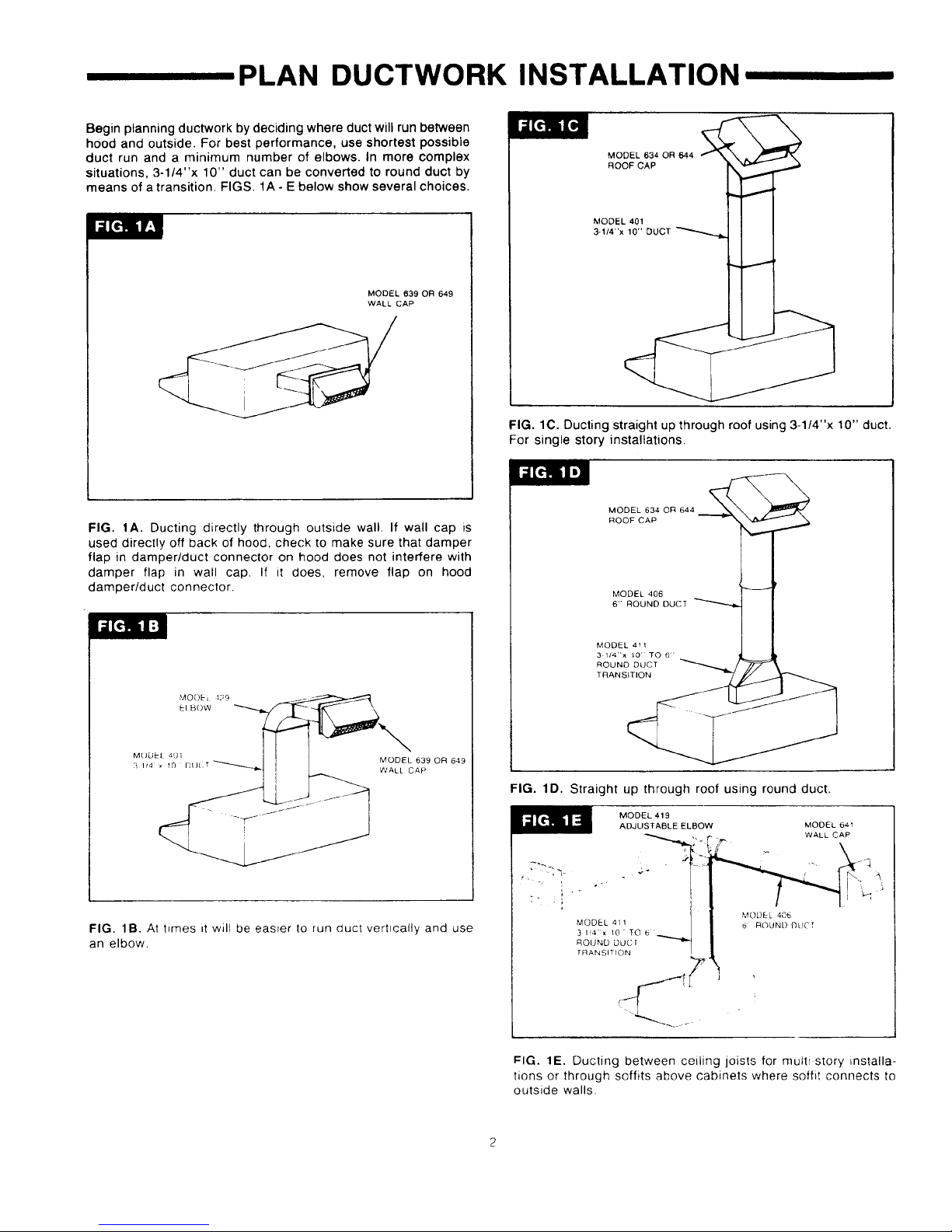
Begin planning ductwork by deciding where duct will run between
hood and outside. For best performance, use shortest possible
duct run and a minimum number of elbows. In more complex
situations, 3-1/4"x 10" duct can be converted to round duct by
means of a transition. FIGS. 1A - E below show several choices.
MODEL 639 OR 649
WALL CAP
FIG. tA. Ducting directly through outside wall. If wall cap is
used directly off back of hood, check to make sure that damper
flap in darnper/duct connector on hood does not interfere with
damper flap in wall cap. If it does, remove flap on hood
damper/duct connector.
MODEL 634 OR 644
ROOF CAP
MODEL 401
3-1/4"x 10" DUCT
FIG. lC. Ducting straight up through roof using 3-1/4"x 10" duct.
For single story installations.
MODEL 634 OR 644
ROOF CAt n
MODEL 406
6'" ROUND DUCT
M()DEL 4UI MODEL 639 OR 649
i 1/4 _ 10 DU( T
WALl CAP
FIG. lB. At hmes ,t will be easter to run duct vertically and use
an elbow.
MODEL 411
ROUND DUCT
TRANSITION
FIG. 1D. Straight up through roof using round duct.
MODEL 419
ADJUSTABLE ELBOW MODEL 641
MODEL 411 1
3 IS'_." x 10 " TO 6 _
R O U'NL) DUC[
TRANSITION
MODEL 405
6 ROUND DUCT
WALL CAP
FIG. 1E. Ducting between ceiling joists for mutti story installa-
tions or through soffits above cabinets where soffit connects to
outside walls.
Step 3
,,, , PREPARE HOOD
1.
Unpack hood and check contents. You should receive:
1 - assembled hood
1 - plastic bag, containing:
4 - 7/8" wood screws for mounting hood to cabinet
2 - 1/4" black sheet metal screws for mounting damper/
duct connector to hood
2 - aluminum tilters
Step 2
1 - damper/duct connector
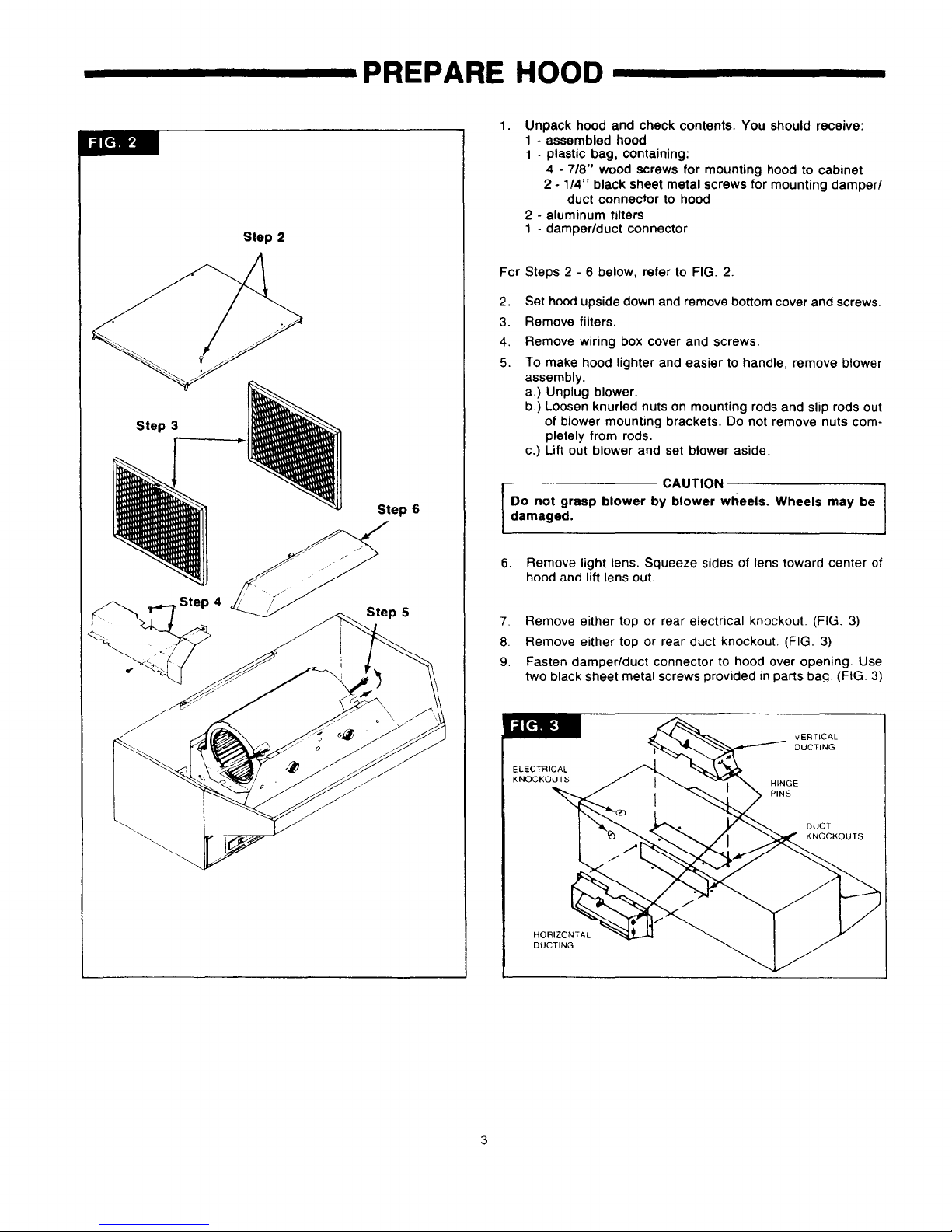
For Steps 2 - 6 below, refer to FIG. 2.
2.
Set hood upside down and remove bottom cover and screws.
3.
Remove filters.
4.
Remove wiring box cover and screws.
5.
To make hood lighter and easier to handle, remove blower
assembly.
a.) Unplug blower.
b.) LOosen knurled nuts on mounting rods and slip rods out
of blower mounting brackets. Do not remove nuts com-
pletely from rods.
c.) Lift out blower and set blower aside.
Step 4
Step 6
s
ep 5
CAUTION
Do not grasp blower by blower wheels. Wheels may be /
damaged.
6. Remove light lens. Squeeze sides of lens toward center of
hood and lift lens out.
7. Remove either top or rear electrical knockout. (FIG 3)
8. Remove either top or rear duct knockout. (FIG. 3)
9. Fasten damper/duct connector to hood over opening. Use
two black sheet metal screws provided in parts bag. (FIG. 3)
ELECTRICAL
KNOCKOUTS
HORIZONTAL
DUCTING
/ DUCTING
HINGE
PINS
VERTICAL
DuCT
KNOCKOUTS
/
J
 Loading...