

Page 1
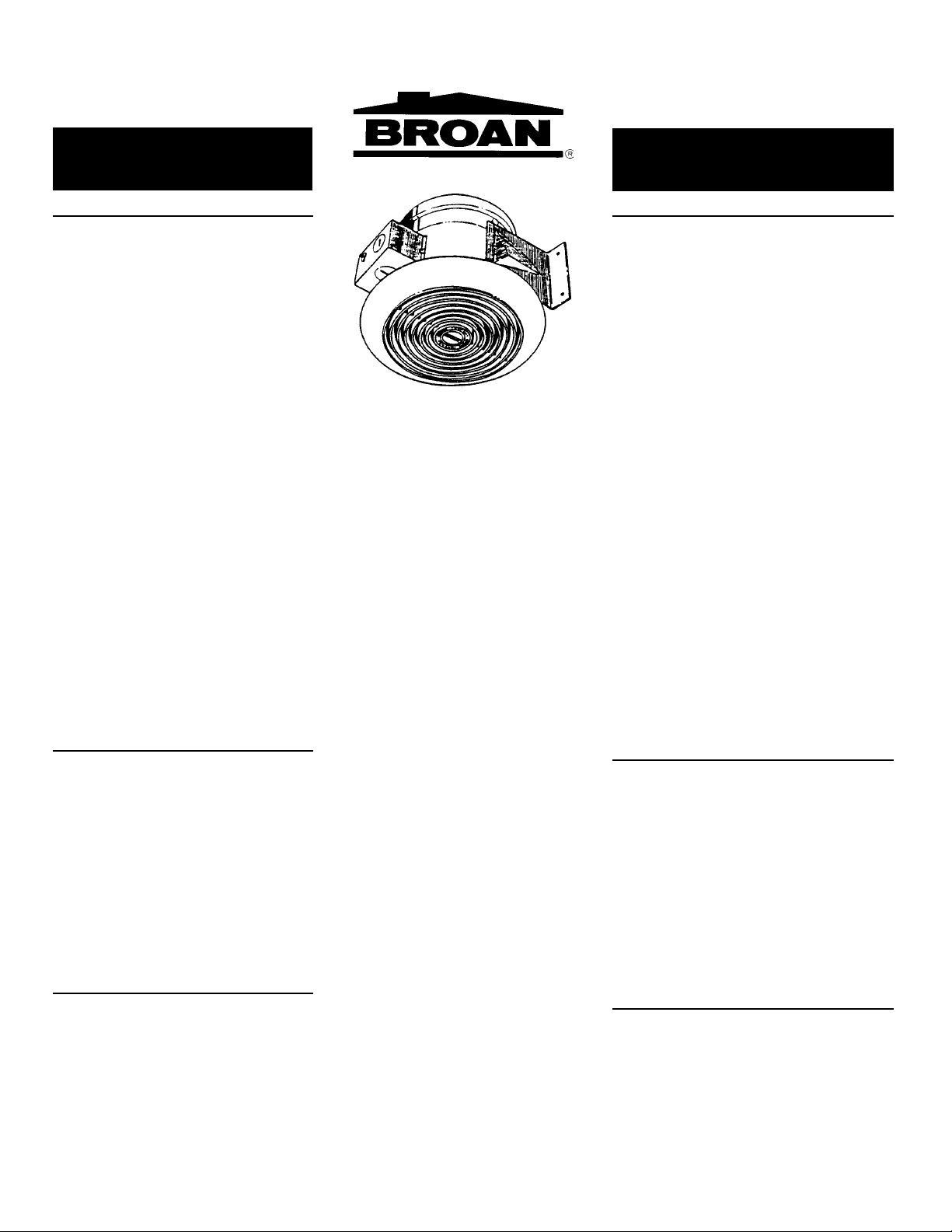
MODELS 673, 673MX
VERTICAL DISCHARGE
CEILING FAN
VENTILADOR DE DESCARGA
VERTICAL PARA CIELO RASO
MODELOS 673, 673MX
READ AND SAVE
THESE INSTRUCTIONS
WARNING
TO REDUCE THE RISK OF FIRE, ELECTRIC
SHOCK, OR INJURY TO PERSONS, OBSERVE THE
FOLLOWING:
1. Use this unit only in the manner intended by the
manufacturer. If you have questions, contact the
manufacturer at the address or telephone number listed in the warranty.
2. Before servicing or cleaning unit, switch power
off at service panel and lock the service disconnecting means to prevent power from being
switched on accidentally. When the service disconnecting means cannot be locked, securely
fasten a prominent warning device, such as a tag,
to the service panel.
3. Installation work and electrical wiring must be
done by a qualified person(s) in accordance with
all applicable codes and standards, including firerated construction codes and standards.
4. Sufficient air is needed for proper combustion and
exhausting of gases through the flue (chimney)
of fuel burning equipment to prevent backdrafting.
Follow the heating equipment manufacturer’s
guideline and safety standards such as those
published by the National Fire Protection Association (NFPA), and the American Society for
Heating, Refrigeration and Air Conditioning Engineers (ASHRAE), and the local code authorities.
5. When cutting or drilling into wall or ceiling, do not
damage electrical wiring and other hidden utilities.
6. Ducted fans must always be vented to the outdoors.
7. If this unit is to be installed over a tub or shower,
it must be marked as appropriate for the application and be connected to a GFCI (Ground Fault
Circuit Interrupter) - protected branch circuit.
8. NEVER place a switch where it can be reached
from a tub or shower.
9. To reduce the risk of fire, use only metal ductwork.
10.This unit must be grounded.
CAUTION
1. For general ventilating use only. Do not use to
exhaust hazardous or explosive materials and vapors.
2. This product is designed for ceiling installation
only. DO NOT MOUNT THIS PRODUCT IN A
WALL!
3. This product is designed to be mounted on ceiling joists (horizontally) only. DO NOT install the
ventilator at any other angle.
4. To avoid motor bearing damage and noisy and/or
unbalanced impellers, keep drywall spray, construction dust, etc. off power unit.
5. Please read specification label on product for further information and requirements.
ADVERTENCIA
PARA REDUCIR EL RIESGO DE INCENDIO, DESCARGA
ELECTRICA, O LESIONES PERSONALES, CUMPLA
CON LOS SIGUIENTES PUNTOS:
CUIDADO
LEA Y CONSERVE
ESTAS INSTRUCCIONES
1. Solamente use esta unidad de la manera propuesta por
el fabricante. Si tiene alguna pregunta, póngase en
contacto con el fabricante en la dirección o teléfono
anotados en la garantía.
2. Antes de limpiar o de poner en servicio la unidad, apague
el interruptor en el panel de servicio, y asegure el panel
de servicio para evitar que se encienda accidentalmente.
Cuando el dispositivo para desconectar el servicio
eléctrico no puede ser cerrado con algún tipo de traba,
sujete fuertemente al panel de servicio, una etiqueta de
advertencia prominente.
3. El trabajo de instalación y el cableado eléctrico deben
llevarse a cabo por personal calificado de acuerdo con
todos los códigos y las normas aplicables, incluyendo
los códigos y normas de construcción contra incendios.
4. Se requiere una cantidad de aire suficiente para la
combustión y escape de gases por la chimenea del
equipo que quema combustible para evitar la
retrogresión de la llama. Siga las especificaciones y
estándares de seguridad del fabricante, tales como los
que publica la Asociación Nacional de Protección Contra
Incendios (NFPA por sus sigles en inglés), y la Sociedad
Americana de Ingenieros de Calefacción, Refrigeración
y Aire Acondicionado (ASHRAE), y los códigos de las
autoridades locales.
5. Cuando corte o taladre en una pared o cielo raso, no
dañe cableado eléctrico u otras instalaciones no visibles.
6. Ventiladores con conductos siempre deben extraer hacia
el exterior.
7. Si esta unidad va a instalarse sobre una tina o ducha
debe marcársela como correcta para dicha aplicación y
debe conectarse a un circuito protegido GFCI
(Cortacicuito Accidental a Tierra).
8. Unca coloque un interruptor donde pueda ser alcanzado
desde un baño o ducha.
9. Para reducir el riesgo de incendio, use solamente
conductos de metal.
10. Esta unidad se debe conectar a tierra.
1. Para uso de ventilación general solamente. No lo use
para extraer materiales o vapores explosivos o
peligrosos.
2. Este producto está diseñado para instalar en el cielo
raso solamente. NO MONTE ESTE PRODUCTO EN
UNA PARED.
3. Este producto está diseñado para montarlo solamente
en vigas de cielo raso (horizontalmente). No lo monte
en ningún otro ángulo.
4. Para evitar daños al cojinete del motor e impulsores
ruidosos y/o desequilibrados, mantenga la unidad de
potencia lejos de rocíos de yeso, polvo de construcción,
etc.
5. Por favor lea la etiqueta con especificaciones del
producto para más información y requisitos.
TOOLS AND MATERIALS
REQUIRED
❏ Straight-blade screwdriver
❏ Hammer
❏ 4 - nails
❏ Wall control
❏ 6” round ductwork and elbows (as needed)
❏ Roof or wall cap
❏ Duct tape
❏ Electrical supplies of type to comply with local
codes
INSTALLER: Leave This Manual With The Homeowner. HOMEOWNER: Use and Care Information on Page 3.
INSTALADOR: Deje este manual con el dueño de casa. DUEÑO DE CASA: Información del uso y mantenimiento en la página 3.
HERRAMIENTAS Y
MATERIALES NECESARIOS
❏ Destornillador de hoja ancha
❏ Martillo
❏ 4 - clavos
❏ Control de pared
❏ Conducto redondo de 15,24 cm (6 pulg.) y codos
(tantos como se necesiten)
❏ Tapa para pared o techo
❏ Cinta de conductos
❏ Cableado eléctrico y artículos del tipo necesario para
cumplir con códigos locales
Page 2

INSTALLATION
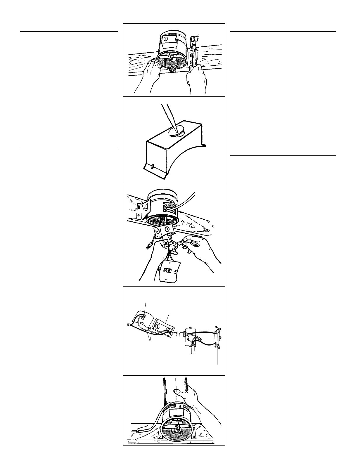
1. Unplug motor, loosen screw and remove outlet
box cover. (FIG. 1)
2. Pull outlet box into housing and lift out. (FIG. 2)
Note: For easier removal of outlet box, you may wish
to remove the motor assembly by loosening the mounting screws and rotating bracket clockwise.
3. Draw a line on joist 3-1/4” from the bottom edge,
as shown, for 1/2” finished ceiling material. Adjust this dimension for different ceiling material
thicknesses. Hold unit up and mark upper keyholes along this line. (FIG. 3)
4. Start two nails in marked locations. Make sure
nail heads are small enough to fit through larger
opening in keyholes, yet large enough to hold unit
securely in smaller keyholes. (FIG. 4)
FIG. 1
FIG. 2
INSTALACION
1. Desenchufe el motor, afloje el tornillo y quite la tapa de
la caja de conexiones. (FIG. 1)
2. Tire la caja de conexiones que está dentro de la caja
principal, y sáquela. (FIG. 2)
Nota: para más facilidad al sacar la caja de conexiones,
usted puede sacar el conjunto del motor aflojando los tornillos de montaje y girando el soporte en el sentido del
reloj.
3. Dibuje una línea en la viga a 8,25 cm (3-1/4 pulg.) del
borde inferior, tal como se muestra, para material de
acabado de cielo raso de 1,27 cm (1/2 pulg.). Ajuste
esta dimensión para otros grosores de materiales de
cielo raso. Sostenga la unidad y marque los agujeros
como llave en esta línea. (FIG. 3)
4. Clave parcialmente dos clavos en los lugares que se
marcaron. Verifique que las cabezas de estos clavos
sean lo suficientemente pequeñas para caber por la parte
más ancha de los agujeros en forma de llave, pero de
un tamaño tal que puedan sostener la unidad con
agujeros más pequeños. (FIG. 4)
FIG. 3
FIG. 4
Page 3
INSTALLATION
5. Hang unit from nails using upper keyholes and
drive nails tight. Use other two nails in lower keyholes and drive tight to secure installation. (FIG.
5)
6. Choose one of the electrical knockouts, on the
outlet box, and remove by bending it back and
forth with a screwdriver. (FIG. 6)
7. Feed power cable through outlet box opening and
at least 6” into outlet box. Attach with appropriate
connector. Wire receptacle to power cable, connecting black to black, white to white, and ground
to ground screw in outlet box. (FIG. 7 & 8)
8. Replace outlet box and outlet box cover removed
in Steps 2 & 3. Replace motor assembly (if removed). Plug in motor.
9. Install 6” round duct and tape joints. Turn power
on and check fan and damper for proper operation. (FIG. 9)
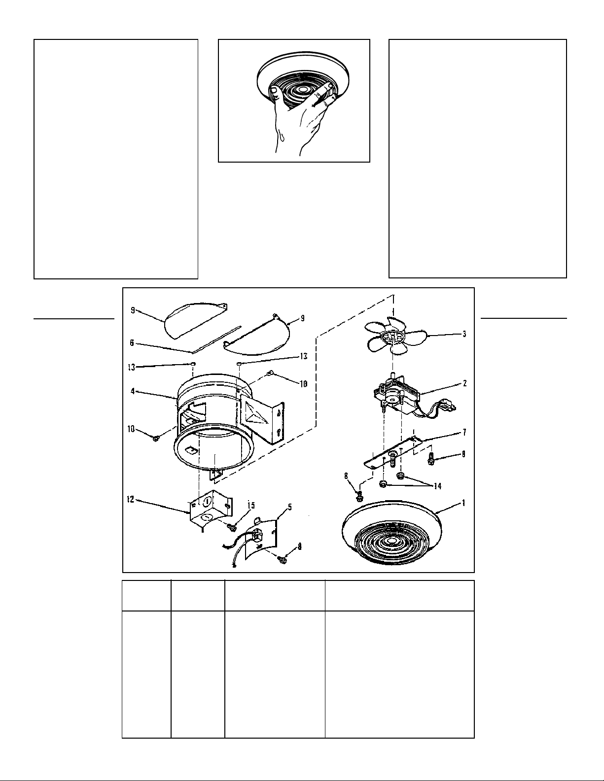
10.After ceiling is finished, install grille by screwing
it onto the grille stud. Tighten grille just enough to
provide a flush appearance without distorting the
grille. (FIG. 10)
USE AND CARE
TO CLEAN FAN ASSEMBLY: Wall switch should be
in “OFF” position. Unplug fan motor cord from black
receptacle. Loosen mounting screws, turn motor and
bracket clockwise and lift out carefully.
Gently vacuum fan, motor and interior of housing.
Motor is permanently lubricated — never needs oiling.
METAL AND ELECTRICAL PARTS SHOULD NEVER
BE IMMERSED IN WATER.
FIG. 5
FIG. 6
FIG. 7
INSTALACION
5. Cuelgue la unidad de los agujeros como llave superiores
y clave los clavos completamente. Clave dos clavos en
los agujeros inferiores y afiance la unidad. (FIG. 5)
6. Escoja uno de los discos removibles de la caja de
conexiones, y sáquelo doblándolo hacia atrás y adelante
con un destornillador. (FIG. 6)
7. Pase el cable de potencia por la abertura de la caja de
conexiones y deje un mínimo de 15,24 cm (6 pulg.) dentro
de dicha caja. Haga la conexión apropiada. Cablee el
receptáculo al cable de potencia, conectando negro con
negro, blanco con blanco, y tierra al tornillo de tierra en
la caja de conexiones. (FIG. 7 y 8)
8. Ponga de nuevo en su lugar la caja de conexiones y su
tapa que se sacaron en pasos 2 y 3. Coloque de nuevo
el conjunto del motor (si es que se sacó). Enchufe el
motor.
9. Instale conducto redondo de 15,24 cm (6 pulg.) y forre
con cinta las uniones. Encienda el ventilador y revise su
funcionamiento y el funcionamiento del amortiguador.
(FIG. 9)
10. Después que el cielo raso esté acabado, instale la rejilla
atornillándola en su montante. Apriete la rejilla lo
suficiente para proporcionar una apariencia de que está
a nivel, pero sin que ella se doble. (FIG. 10)
USO Y MANTENIMIENTO
PARA LIMPIAR EL CONJUNTO DEL VENTILADOR: el
conmutador de pared debe estar en la posición de “OFF”
(apagado). Desenchufe el cable del motor del ventilador
del receptáculo negro. Afloje los tornillos de montaje, gire
el motor y el soporte en el sentido del reloj y sáquelo
cuidadosamente.
Pase una aspiradora suavemente por el ventilador, motor
e interior de la caja. El motor viene permanentemente
lubricado — no necesita aceite.
EL METAL Y LAS PIEZAS ELECTRICAS NO SE DEBEN
METER DENTRO DEL AGUA.
FIG. 8
FAN RECEPTACLE
RECEPTACULO DEL VENTILADOR
BLACK
NEGRO
WHITE
BLANCO
CONMUTADOR DE CODILLO O TEMPORIZADOR
FIG. 9
GROUND (BARE OR GREEN WIRE)
TIERRA (CABLE VERDE O DESNUDO)
BLACK
NEGRO
WHITE
SWITCH
BOX
CAJA DE
CONMUTACION
LINEA DE ENTRADA
BLANCO
BLACK
NEGRO
LINE IN
TOGGLE SWITCH OR TIMER
Page 4
BROAN ONE YEAR LIMITED WARRANTY
Broan warrants to the original consumer purchaser of its products that such products will be free from defects in materials or
workmanship for a period of one year from the date of original
purchase. THERE ARE NO OTHER WARRANTIES, EXPRESS
OR IMPLIED, INCLUDING, BUT NOT LIMITED TO, IMPLIED WARRANTIES OF MERCHANTABILITY OR FITNESS FOR A PARTICULAR PURPOSE.
During this one-year period, Broan will, at its option, repair or
replace, without charge, any product or part which is found to be
defective under normal use and service.
THIS WARRANTY DOES NOT EXTEND TO FLUORESCENT
LAMP STARTERS AND TUBES. This warranty does not cover (a)
normal maintenance and service or (b) any products or parts
which have been subject to misuse, negligence, accident, improper maintenance or repair (other than by Broan), faulty installation or installation contrary to recommended installation instructions.
The duration of an implied warranty is limited to the one-year
period as specified for the express warranty. Some states do not
allow limitation on how long an implied warranty lasts, so the
above limitation may not apply to you.
BROAN’S OBLIGATION TO REPAIR OR REPLACE, AT BROAN’S
OPTION, SHALL BE THE PURCHASER’S SOLE AND EXCLUSIVE
REMEDY UNDER THIS WARRANTY. BROAN SHALL NOT BE LIABLE FOR INCIDENTAL, CONSEQUENTIAL OR SPECIAL DAMAGES ARISING OUT OF OR IN CONNECTION WITH PRODUCT
USE OR PERFORMANCE. Some states do not allow the exclusion
or limitation of incidental or consequential damages, so the above
limitation may not apply to you.
This warranty gives you specific legal rights, and you may also have
other rights, which vary from state to state. This warranty supersedes
all prior warranties.
To qualify for warranty service, you must (a) notify Broan at the
address or telephone number below, (b) give the model number
and part identification and (c) describe the nature of any defect
in the product or part. At the time of requesting warranty service,
you must present evidence of the original purchase date.
Broan-NuTone LLC,
926 West State Street
Hartford, WI 53027
(1-800-637-1453)
FIG. 10
Broan garantiza al consumidor comprador original de sus productos
que dichos productos carecerán de defectos en materiales o en mano
de obra por un período de un año a partir de la fecha original de compra.
NO EXISTEN OTRAS GARANTIAS, NI EXPLICITAS NI IMPLICITAS,
INCLUYENDO, PERO NO LIMITADAS A, GARANTIAS IMPLICITAS DE
COMERCIALIZACION O APTITUD PARA UN PROPOSITO PARTICULAR.
Durante el período de un año, y a su propio criterio, Broan reparará o
reemplazará, sin costo alguno, cualquier producto o pieza que se encuentre
defectuosa bajo condiciones normales de servicio y uso.
ESTA GARANTIA NO SE APLICA A TUBOS Y ARRANCADORES DE
LAMPARAS FLUORESCENTES. Esta garantía no cubre (a) mantenimiento
y servicio normales ni (b) cualquier producto o piezas que hayan sido
utilizadas de forma errónea, negligente, que hayan tenido un accidente, o
que hayan sido reparadas o mantenidas incorrectamente (por otras personas o compañías que no sean Broan), instalación defectuosa, o instalación
contraria a las instrucciones de instalación recomendadas.
La duración de cualquier garantía implícita se limita a un período de un año
como se especifica en la garantía expresa. Algunos estados no permiten
limitaciones en cuanto al tiempo de expiración de una garantía implícita,
por lo que la limitación antes mencionada puede no corresponderle.
LA OBLIGACION DE BROAN DE REPARAR O REEMPLAZAR, SIGUIENDO
EL CRITERIO DE BROAN, DEBERA SER EL UNICO Y EXCLUSIVO
RECURSO LEGAL DEL COMPRADOR BAJO ESTA GARANTIA. BROAN
NO SERA RESPONSABLE POR DAÑOS INCIDENTALES,
CONSIGUIENTES, O POR DAÑOS ESPECIALES RESULTANTES A RAIZ
DEL USO O DESEMPEÑO DEL PRODUCTO.
Algunos estados no permiten la exclusión o limitación de daños accidentales
o consiguientes, por lo que la limitación antes mencionada puede no aplicarse
a usted.
Esta garantía le proporciona derechos legales específicos, y usted puede
también tener otros derechos, los cuales varían de estado a estado. Esta
garantía reemplaza todas las garantías anteriores.
Para tener derecho al servicio de garantía, usted debe (a) notificar a Broan
en la dirección o al número de teléfono que se menciona abajo, (b) dar
el número del modelo y la identificación de la pieza, y (c) describir la
naturaleza de cualquier defecto en el producto o pieza. En el momento
de solicitar servicio cubierto por la garantía, usted debe presentar
comprobación de la fecha original de compra.
GARANTIA BROAN LIMITADA POR UN AÑO
926 West State Street Hartford, WI 53027
Broan-NuTone LLC,
(1-800-637-1453)
SERVICE
PARTS
MODELS 673, 673MX
PIEZAS DE
SERVICIO
MODELOS 673, 673MX
Always order by “Part
No.” NOT by “Key No.”
KEY NO.
NUMERO
DE CODIGO
1
2
3
4
5
6
7
8
9
10
12
13
14
15
PART NO.
NUMERO
DE PIEZA
99110454
99080199
99080547
99020125
97005321
99270982
98004935
97005322
99170245
98004934
99100379
98005329
99100405
99260428
99150471
DESCRIPTION
Grille
Motor (673)
Motor (673MX)
Plastic Blade
Housing
Receptacle
Damper Rod
Motor Plate
8B x 3/8 Slotted Head (3 req.)
Damper Half (2 req.)
Closed End Bushing
Outlet Box
Pad Damper (2 req.)
6-32 Nut (2 Req.)
Grounding Screw
Broan-NuTone LLC, 926 West State Street, Hartford, WI 53027 (1-800-637-1453)
DESCRIPCION
Rejilla
Motor (673)
Motor (673MX)
Hoja plástica
Caja
Receptáculo
Vara del amortiguador
Placa del motor
8Bx3/8 con ranura en la cabeza (Se req. 3)
Mitad del amortiguador (Se req. 2)
Casquillo con un extremo ciego
Caja de conexiones
Almohadilla del amortiguador (Se req. 2)
Tuerca 6-32 (Se req. 2)
Tornilla de tierra
Ordene siempre por
“Número de pieza”,
NO por “Número de
código”.
99043227A
 Loading...