

Brita Platinum Performance, BPF89CB75TO, BPF89CBK100TOK, BPF89CB300TO, BPF89CBK75TOK Installation Manual
...
PLATINUM
TASTE AND ODOR (TO)
MULTIMEDIA (MM)
FILTER
NEXSAND
NEUTRALIZER (NU)
BIRM (BM)
Professional
Installation
MANUAL
Version V1.0F
54565
THROUGHOUT YOUR HOME | THROUGHOUT YOUR LIFE
The Platinum Carbon Filter Series is certified by
IAPMO R&T to NSF/ANSI 42 for chlorine, taste
and odor reduction.
The Platinum Catalytic Carbon Filter Series
is certified by IAPMO R&T to NSF/ANSI 42 for
chloramine, chlorine taste and odor reduction.
The Platinum Neutralizer Filter Series is
certified by IAPMO R&T according to NSF/ANSI
42 for low pH adjustment.
The Platinum Nexsand Filter Series is certified
by IAPMO R&T to NSF/ANSI 42 for Particulate
Class V reduction.
2
2
This control value and pressure tank is Tested
and Certified by NSF International against
NSF/ANSI Standard 44 for material and
structural integrity requirements.
COMPONENT
828.449.2536
BRITA® PRO
www.britapro.com
BRITA®PRO trademark and logo are registered trademarks of Brita LP and are
used under license by Protect Plus, LLC. All rights reserved
420 3rd Avenue NW
Hickory, NC 28601

READ THIS PAGE FIRST
CONTENTS
BEFORE STARTING INSTALLATION 4
BASICS
HOW YOUR FILTER WORKS 5
COMPONENTS & SPECIFICATIONS
SPECIFICATIONS 6
INSTALLATION
UNPACK & INSTALL 8
CHECK VALVE SERIAL NUMBER & VALVE TYPE 10
PREINSTALLATION INSTRUCTIONS 11
ELECTRICAL GROUNDING 11
TOOLS REQUIRED FOR INSTALLATION 14
DETERMINING LOCATION 14
CHECK WATER PRESSURE AND PUMPING RATE 14
FILTER INSTALLATION 15
MEDIA INSTALLATION 16
OPERATION
STARTUP PROCEDURES 20
DIAGNOSTIC CHECKLIST 21
DURING REGENERATION 21
PLUMBING SYSTEM CLEANUP 21
SOFTENERWATER BYPASSOPERATING CONDITIONS 22
MAINTENANCE INSTRUCTIONS 23
BACKWASHING INSTRUCTIONS 24
CALCULATE BACKWASH FREQUENCY 24
SERVICE THE PLATINUM VALVE 24
PROGRAMMING
MASTER PROGRAMMING 25
DIAGNOSTIC SCREEN 27
REPLACEMENT
REPLACE PISTON &/OR BRINE VALVE 28
CLEAN INJECTOR ASSEMBLY 28
REPLACE TIMER 29
REPLACE MOTOR 29
REPLACE METER ASSEMBLY 30
DISPLAY REPLACEMENT 31
REPLACE MICROSWITCHES 31
AFTER SERVICING 31
DRAIN LINE FLOW CONTROL 32
BRINE LINE FLOW CONTROL 32
PARTS
FILTER 33
CONTROLLER ASSEMBLY PARTS LIST 34
STANDARD BYPASS ASSEMBLY PARTS LIST 35
STANDARD VALVE BODY ASSEMBLY PARTS LIST 36
TROUBLE SHOOTING GUIDE 38
PERFORMANCE DATA STATEMENT 41
WARRANTY 47
3
READ THIS
PAGE FIRST
BEFORE STARTING INSTALLATION
You must read and understand the contents of this manual
before installing or operating your water softener. Personal injury
or property damage could result if you fail to follow instructions in
this manual.
This system and its installation must comply with state and
local regulations. Check with your local public works department
for plumbing and sanitation codes. Local codes should be
followed In the event the codes conflict with any content in this
manual.
For installations in Massachusetts, Massachusetts Plumbing
Code 248 CMR shall be adhered to. Consult your licensed plumber
for installation of this system.
This water softener must be operated on pressures
between 30 psi to 125 psi. If the water pressure is higher than 125
PSI, use a pressure reducing valve in the water supply line to the
softener.
This unit must be operated at temperatures between 40°F and
110°F (4°C - 43°C).
Do not use this water softener on hot water supplies.
Do not install this unit where it may be exposed to wet
weather, direct sunlight, or temperatures outside of the
range specified above.
Apply provided NSF certified lubricant to all o-rings during
installation. Do not use pinched or damaged o-rings during
installation.
Softeners are exposed to high levels of iron, manganese,
sulfur, and sediments. Damage to pistons, seals, and or spacers
within the control valve are not covered in this warranty due to the
harsh environment.
It is recommended to annually inspect and service the control
valve. Frequent cleaning and or replacement of piston, seals,
and or spacers may be necessary depending on how harsh the
conditions are. An Annual Maintenance kit (Part # 60010307) is
available for this purpose.
Do not use water that is microbiologically unsafe without
adequate disinfection before or after this system.
This publication is based on information available when
approved for printing. Continuing design refinement could
cause changes that may not be included in this publication.
See page 8 for unpack and inspect system
BRITA®PRO reserves the right to change the specifications
referred to in this literature at any time, without prior notice.
4
INSTALL
NOTES &
SAFETY
MESSAGES
Watch for the
following messages
in this manual:
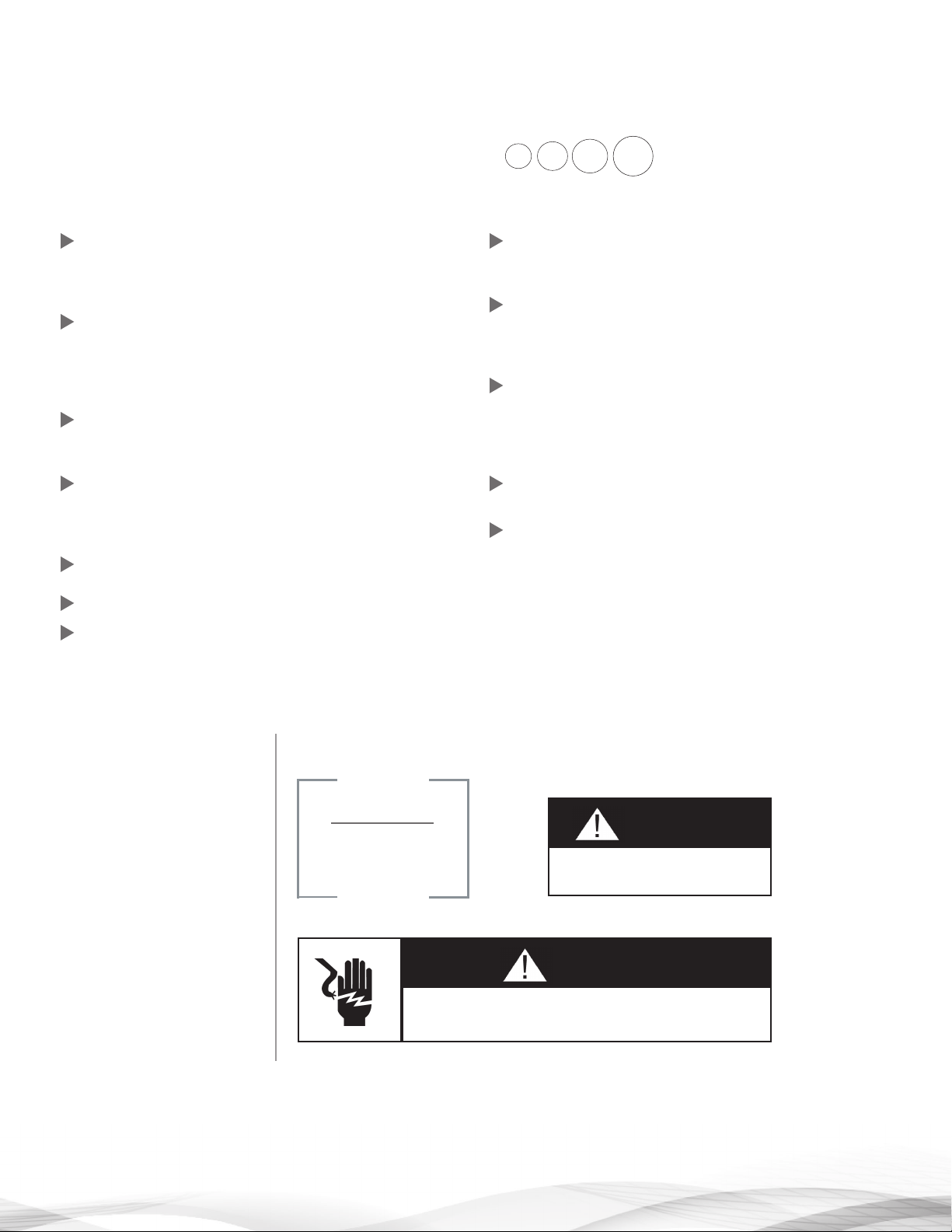
EXAMPLE:
NOTE
Check and comply with
your state and local
codes. You must follow
these guidelines.
EXAMPLE:
EXAMPLE:
CAUTION
Disassembly while under pressure
can result in flooding.
WARNING
ELECTRICAL SHOCK HAZARD! Unplug the unit before removing
the cover or accessing any internal control parts

BASICS
The success of the installation will depend, to a great
extent, on advanced planning and preparation. Careful
attention to the location of the unit, accessibility to
electrical and drain facilities, and the availability of the
proper tools will ensure a professional-looking installation.
Of utmost importance is the assurance that the filter has
been properly applied and meets all specifications.
APPLICATION:
Correct application is directly associated with the
performance and life expectancy of any water filter. It is
important, therefore, to understand how your Brita® Pro
Water Filter functions and to know its capabilities and
limitations so that a correct application can be made.
By following the guidelines and recommendations set forth
in this manual, you can be certain your filter is applied
correctly.
MM / NEXSAND FILTER
The Automatic Water Filter is capable of removing
particulate matter particle size as small as 30 microns.
It will not remove color, organics, colloidal turbidity or
dissolved solids. Some applications include:
- Removal of suspended matter in any water system
- Removal of particulate matter, such as clay, mud, etc.
- Prefiltration of oxidized iron prior to an automatic or
manual softener
-Removal of light sand
The quality and number of gallons of filtered water
between backwashes will depend upon the amount, type,
and size of the particulate matter being filtered. If a water
sample is sent to a laboratory, where application of a MMF
Type unit is contemplated. The laboratory will test for
Nephelometric Turbidity Units (NTU) and suspended solids
(mg/L). The sample will also be filtered through 10 micron
filter paper and NTU run on a filtered sample. If the NTU
of the raw water exceeds 150, suspended solids exceed
150 mg/L, or the filter water through the 10 micron filter
paper has unacceptable quality, a MMF filter might not
be applicable. As a guide, the U.S. Public Health Drinking
Water standards states the turbidity should not exceed
1 NTU. The exact number of gallons filtered between
backwashes can not be given because of many variables.
TO FILTER
Automatic Water Filter with Activated Media will control
chlorine taste and odor, and it will also remove most
objectional organic colors. It will not remove hydrogen
sulfide. It is important to note that whenever the cause
of an objectional taste or odor has not been established,
Health Authorities should determine if the water is safe
to drink. Do not use with water that is microbiologically
unsafe or of unknown quality without adequate disinfection
before or after the system.
NU FILTER*
Automatic Water Filter with Neutralizing Media will
neutralize slightly acid water (pH 5.2 to >6.8) and thus help
to prevent unsightly brown or green stains due to corrosion
of household plumbing. If the pH is between 5 and 6, one
part of Magnesium Oxide Media should be mixed with five
parts of Calcite Media to provide additional neutralizing
capability. If the water to be treated has a pH less than 5, a
high hardness, or a high carbon dioxide level, NF might not
be applicable; a solution feeder should be used. Because
NF adds hardness, it should be used prior to a softener.
BM FILTER
This media acts as a catalyst for the removal of iron and
manganese from the water but require pre-oxidation. This
media removes the iron and manganese from the water.
This is not recommended to remove hydrogen sulfide from
the water and requires high pH water. The media is not
sacrificial hence no replenishment is required.
NOTE
Under dynamic conditions it might be necessary to mix five parts
Calcite with one part Magnesium Oxide to effectively raise the pH.
In order to size and apply the equipment correctly, a complete
analysis of the water supply should be obtained.
5
COMPONENTS &
SPECIFICATIONS
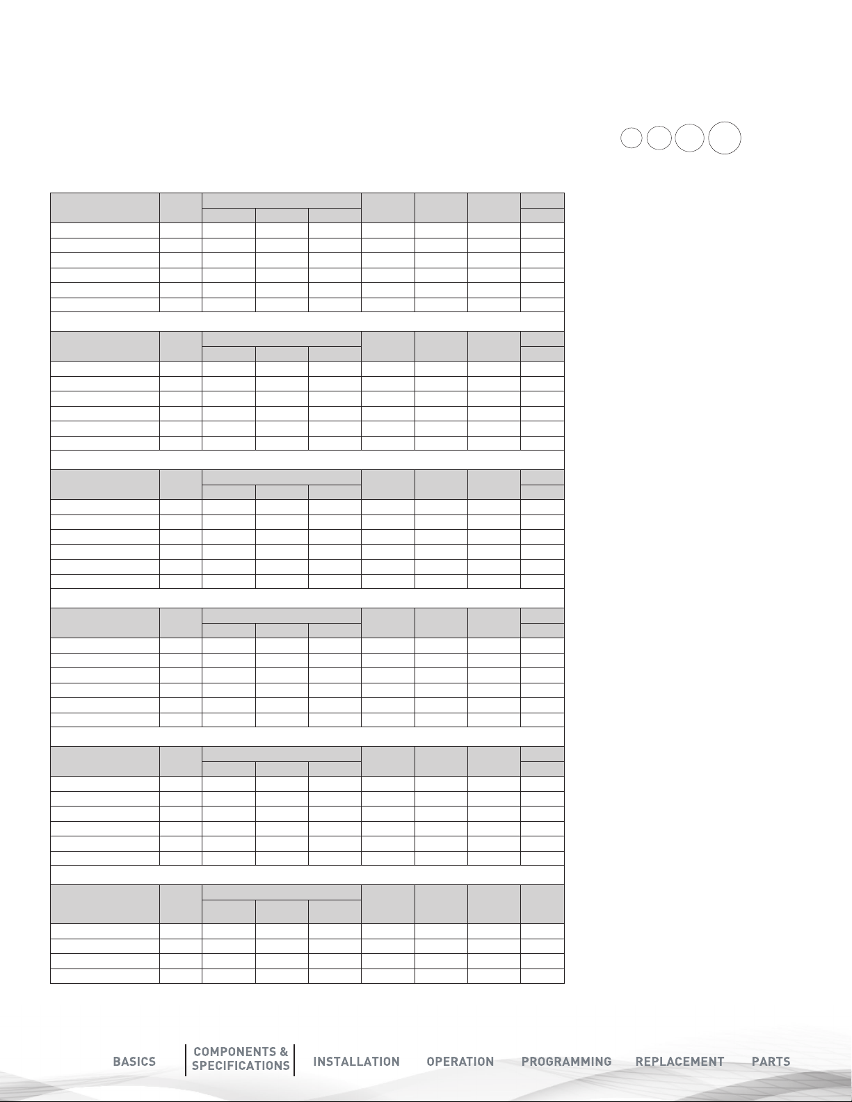
TASTE & ODOR (COCONUT SHELL CARBON) FILTERS
Platinum Series
BPF89CB75TO 0.75 4.0 5.0 3.5 8 x 44 3/4” - 1” 50
BPF89CB100TO 1.00 5.0 7.0 4.0 9 x 48 3/4” - 1” 60
BPF89CB150TO 1.50 7.0 10.0 5.0 10 x 54 3/4” - 1” 78
BPF89CB200TO 2.00 10.0 12.0 7.0 12 x 52 3/4” - 1” 95
BPF89CB300TO 3.00 12.0 15.0 10.0 14 x 65 3/4” - 1” 138
Media Cu
Ft
TASTE & ODOR (COCONUT SHELL CARBON) FILTERS W/KDF
Platinum Series
BPF89CBK75TOK 0.75 4.0 5.0 3.5 8 x 44 3/4” - 1” 50
BPF89CBK100TOK 1.00 5.0 7.0 4.0 9 x 48 3/4” - 1” 60
BPF89CBK150TOK 1.50 7.0 10.0 5.0 10 x 54 3/4” - 1” 78
BPF89CBK200TOK 2.00 10.0 12.0 7.0 12 x 52 3/4” - 1” 95
BPF89CBK300TOK 3.00 12.0 15.0 10.0 14 x 65 3/4” - 1” 138
Media Cu
Ft
Flow Rate USGPM
Flow Rate USGPM
Service Peak Backwash
Mineral
Tank Size
Mineral
Tank Size
Pipe Size
Inches
Pipe Size
Inches
Ship Weight
LbsService Peak Backwash
Ship Weight
Lbs
Working Temperature = 34-110°F
(1-43°C)
(Do not subject the unit to freezing
temperatures)
Working Pressure = 30-125 PSIG
(137-861 kPa)
Voltage = 120V / 60 Hz
Pipe Size = 3/4” and 1”
• At the stated service flow rates, the
pressure drop through these devices
will not exceed 15 psig.
CATALYTIC CARBON FILTERS (CHLORAMINES REDUCTION)
Platinum Series
BPF89CATCB75TOC 0.75 4.0 5.0 3.5 8 x 44 3/4” - 1” 50
BPF89CATCB100TOC 1.00 5.0 7.0 4.0 9 x 48 3/4” - 1” 60
BPF89CATCB150TOC 1.50 7.0 10.0 5.0 10 x 54 3/4” - 1” 78
BPF89CATCB200TOC 2.00 10.0 12.0 7.0 12 x 52 3/4” - 1” 95
BPF89CATCB300TOC 3.00 12.0 15.0 10.0 14 x 65 3/4” - 1” 138
Media Cu
Ft
Flow Rate USGPM
Mineral
Tank Size
Pipe Size
Inches
Ship Weight
LbsService Peak Backwash
CATALYTIC CARBON FILTERS (CHLORAMINES REDUCTION) W/ KDF
Platinum Series
BPF89CATCBK75TOCK 0.75 4.0 5.0 3.5 8 x 44 3/4” - 1” 50
BPF89CATCBK100TOCK 1.00 5.0 7.0 4.0 9 x 48 3/4” - 1” 60
BPF89CATCBK150TOCK 1.50 7.0 10.0 5.0 10 x 54 3/4” - 1” 78
BPF89CATCBK200TOCK 2.00 10.0 12.0 7.0 12 x 52 3/4” - 1” 95
BPF89CATCBK300TOCK 3.00 12.0 15.0 10.0 14 x 65 3/4” - 1” 138
Media Cu
Ft
Flow Rate USGPM
Mineral
Tank Size
Pipe Size
Inches
Ship Weight
LbsService Peak Backwash
NEUTRALIZING FILTERS
Platinum Series
BPF89NEU75PH 0.75 2.0 3.5 3.5 8 x 44 3/4” - 1” 93
BPF89NEU100PH 1.00 3.0 5.0 4.0 9 x 48 3/4” - 1” 120
BPF89NEU150PH 1.50 5.0 8.0 5.0 10 x 54 3/4” - 1” 164
BPF89NEU200PH 2.00 6.0 10.0 7.0 12 x 52 3/4” - 1” 207
BPF89NEU300PH 3.00 7.0 12.0 10.0 14 x 65 3/4” - 1” 330
Media Cu
Ft
Flow Rate USGPM
Mineral
Tank Size
Pipe Size
Inches
Ship Weight
LbsService Peak Backwash
• The manufacturer reserves the right
to make product improvements which
may deviate from the specifications
and descriptions stated herein,
without obligation to change previously
manufactured products or to note the
change.
* Do not use water that is
microbiologically unsafe without
adequate disinfection before or after
the system.
Peak flow rates intended for intermittent
use only (10 minutes or less) and are
for residential applications only. Do
not use peak flow rate for commercial
applications or for a continuous
rate when treated water supplies are
geothermal heat pump, swimming
pool, etc.
For satisfactory operation, the pumping
rate of the well system must equal or
exceed indicated backwash flow rate.
All units come with plastic bypass.
NEXSAND PARTICULATE FILTERS
Platinum Series Media Cu
Ft
BPF89NEX75TUR 0.75 4.0 6.0 5.0 3 - 5 µ 8 x 44 3/4” - 1” 90
BPF89NEX100TUR 1.00 5.0 8.0 7.0 3 - 5 µ 9 x 48 3/4” - 1” 135
BPF89NEX150TUR 1.50 8.0 10.0 10.0 3 - 5 µ 10 x 54 3/4” - 1” 205
BPF89NEX200TUR 2.00 10.0 12.0 14.0 3 - 5 µ 12 x 52 3/4” - 1” 255
Flow Rate USGPM
Micron
Rating
Mineral
Tank Size
Pipe Size
Inches
6
Ship
Weight
LbsService Peak Backwash
WATER AND TIME CONSUMED
DURING REGENERATION
Models Backwash
Minutes
75 10 10 20 70 80 100
100 10 10 20 80 100 140
150 10 10 20 100 140 200
200 10 10 20 140 200 280
300 10 10 20 200 280 340
Rapid Rinse
Minutes
Total
Time of
Regeneration
Total Water
Consumed during
Regeneration (GAL)
(Birm, TO, Neu)
Total Water Consumed
during Regeneration
(GAL) (MM)
Total Water Consumed
B
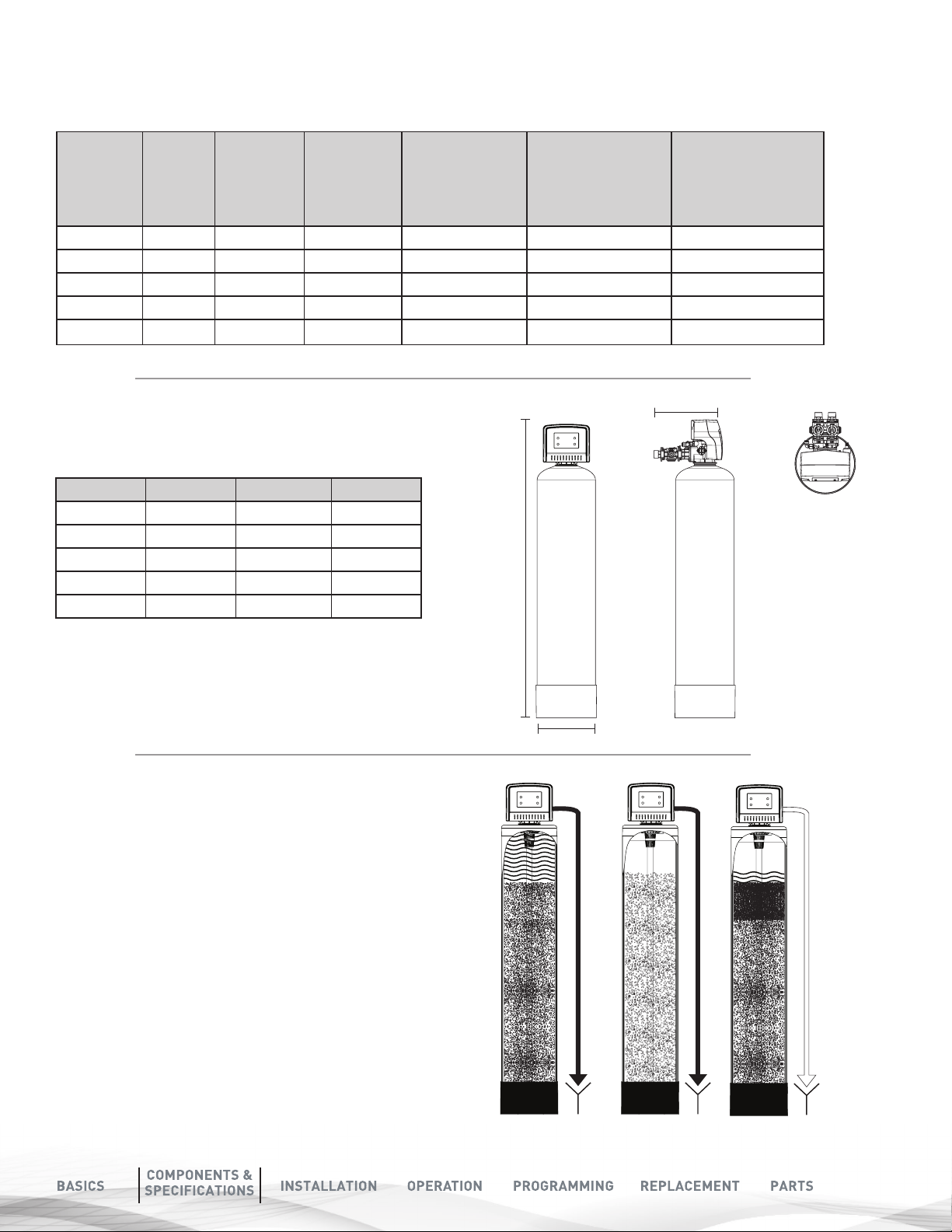
SYSTEM DIMENSIONS
Models A (Inches) B (Inches) C (Inches)
75
100
150
200
300
51.5 13" 8"
55.5 15" 9"
61.5 16" 10"
59.5 17" 12"
72.5 18" 14"
A
during Regeneration
(GAL) (Nexsand)
CONTROL VALVE
REGENERATION
SEQUENCE
The regeneration cycle goes through 3 steps.
1. BACKWASH (MINIMUM 30 PSI INLET
PRESSURE REQUIRED): During the backwash cycle, water
flows upwards through the bed, expanding the media and
carrying any contaminants trapped within it to the drain.
2. RAPID RINSE: During the rapid rinse cycle, water flows
downwards through the bed, settling the media and carrying
any precipitated contaminants trapped within it to the drain.
3. INSERVICE POSITION: The unit then returns to the In-Service
position. While this happens water continues to enter the tank.
C
Step1 Step 2
Step 3
7
INSTALLATION
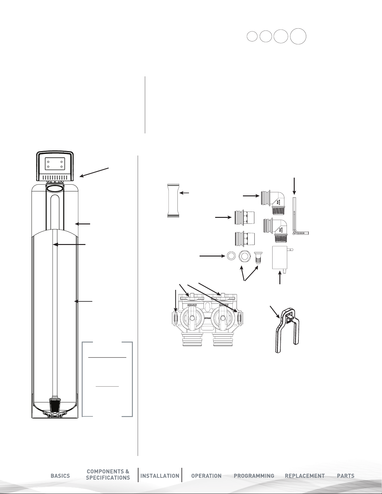
UNPACK & INSPECT PLATINUM FILTER
PLATINUM FILTER CONTENTS:
FOR MODELS 75,100,150, TO200, BIRM200,
YOU WILL EXPECT THE FOLLOWING.
SHIPPING CARTON QUANTITY 1
1. Control Valve
2. Pressure Tank
3. Parts Box
4. Owners Manual
5. Drain Hose & Clamp
(Not included in some brands)
1. CONTROL
VALVE
2. TANK
Distributor
Tube Inside
the Tank
• Check the entire unit for any shipping damage or lost parts.
• Note any damage to the shipping cartons.
• Contact the transportation company for all damage and loss claims.
• The manufacturer is not responsible for damages in transit.
• Small parts needed to install the softener are in a parts box.
• To avoid loss of the small parts keep them in the parts bag until you are ready to install.
• Handle the softener unit with care.
• Do not drop the unit or set on sharp uneven projections on the floor.
• Do not turn the softener unit upside down.
3. PARTS BOX
Grease
Packet
2X 1”
Straight
Adapter
Drain Line
Gasket
2 X 1”
Elbow
Adapter
(Not
Included)
Bypass Tool
Media Inside
the Tank.
Media Type will
depend on what
models were
purchased
NOTE
Only 8”, 9” & 10”
Pressure tanks
have plastic
sleeves.
8”, 9” & 10” tanks
come filled with
media & control
value attached
Bypass with 4
Red Clips
Drain Hose Barb
2 x Clips
Transformer
8
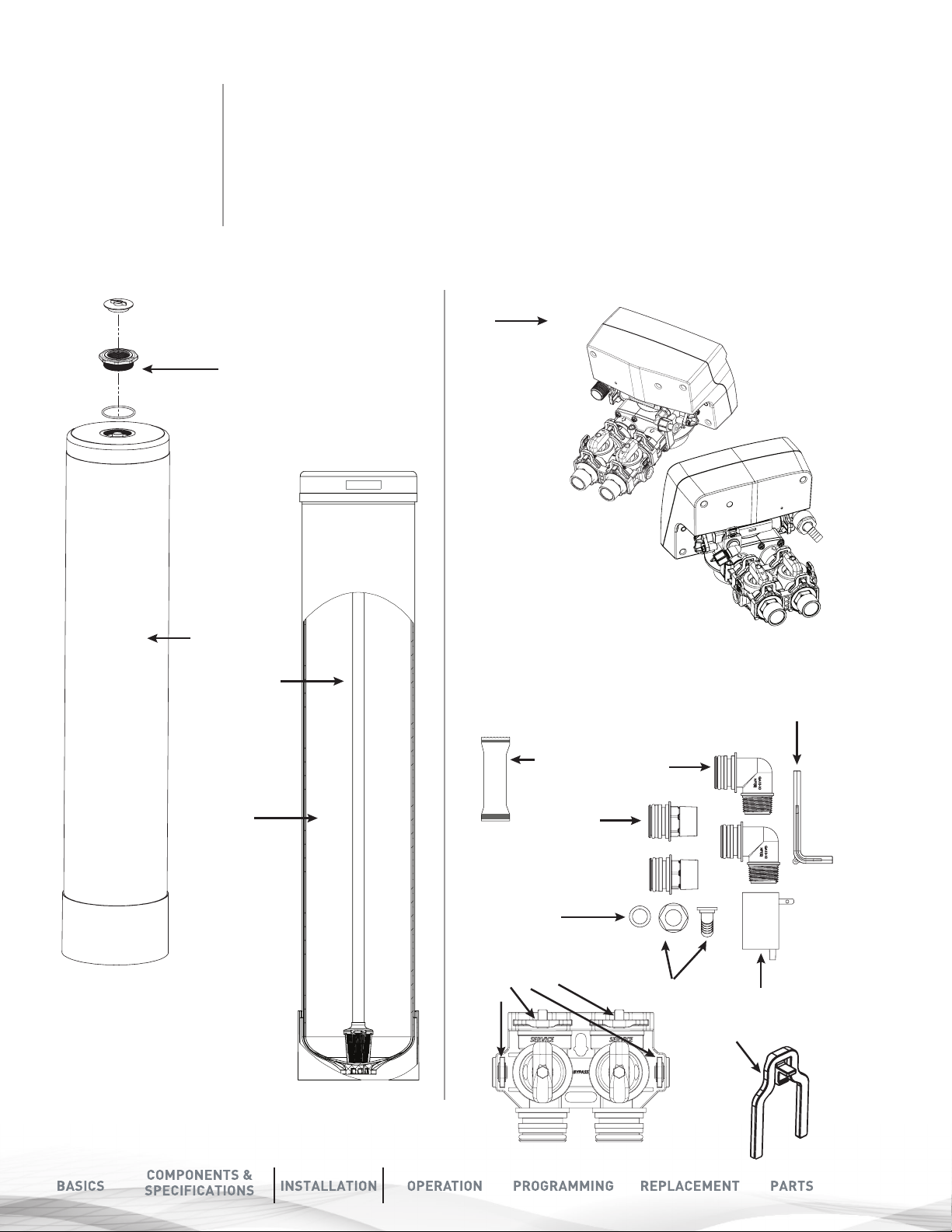
FOR MODELS 200, 300
THE MEDIA AND
CONTROL VALVE
IS PACKAGED
SEPARATELY IN
CARTON AND BAGS
Model 300 will get
Adaptor and O-ring
PLATINUM FILTER CONTENTS :
200, 300
1. Tank
(Model 30 will get an Adaptor and O-ring attached to the tank)
2. Control Valve with Parts Box
3. Media Boxes (Qty 2 for 200, Qty 3 for 300
4. Drain Line and Hose Clamp (Not Included) with some models
2. CONTROL
VALVE
Shown
1. TANK
Distributor
Tube Inside
the Tank
Media Inside
the Tank.
Media Type will
depend on what
models were
purchased
3. PARTS BOX
Grease
Packet
2X 1”
Straight
Adapter
Drain Line
Gasket
Bypass with 4
Red Clips
2 X 3/4”
Elbow
Adapter
(Not
Included)
Drain Hose Barb
2 x Clips
Bypass Tool
Transformer
9
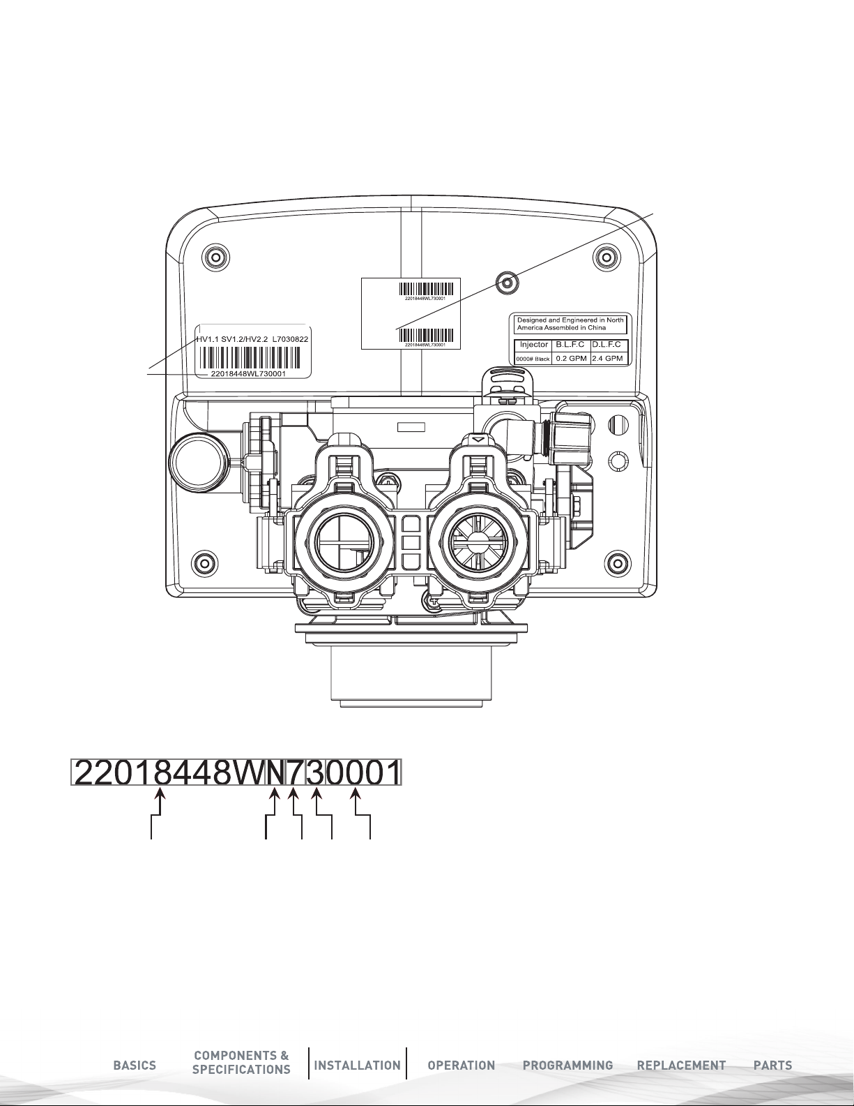
CHECK THE VALVE SERIAL NUMBER
AND VALVE TYPE
Check to make sure the valve type matches what you ordered.
The serial # label on the left will show BPCVPLATUF for Upflow valve
The right Sticker shows the serial # of the control valve.
The middle Sticker is dataplate which provides information of Serial # and Date of Manufacture of complete system.
Both Serial # labels are important for troubleshooting.
COMPLETE SYSTEM
SERIAL NUMBER
Item #
Desc
Date of Manufacture
BPCVPLATUF
VALVE SERIAL
NUMBER
Serial #
VALVE SERIAL NUMBER:
10
(22018448W): Part #
(L)YEAR : ’’ N’’ stand for 2017 year,’’ M’’ stand for 2016
year,’’ L’’ stand for 2015, ’’K’’ stand for 2014, ’’J’’ stand for
2013
Year Month Date Batch #Part #
(7)MONTH: 1 (JAN) 2(FEB) 3(MAR) 4(APRIL) 5(MAY)
6(JUNE) 7(JULY) 8(AUG) 9(SEP) A(OCT) B(NOV) C(DEC)
(3)DATE: 1 2 3 4 5 6 7 8 9 A(10) B(11) C(12) D(13) E(14)
F(15) G(16) H(17) I(18) J(19) K(20) L(21) M(22) N(23) O(24)
P(25) Q(26) R(27) S(28) T(29) U(30) V(31)
(0001): Batch code
PRE-INSTALLATION INSTRUCTIONS
CHECK YOUR WATER HARDNESS
Use test strips (Part # 2793828-20) to get an estimation of water hardness. Contact your local BRITA®PRO dealer to use a
BRITA®PRO laboratory for a complete water analysis free of cost and no obligation to you.
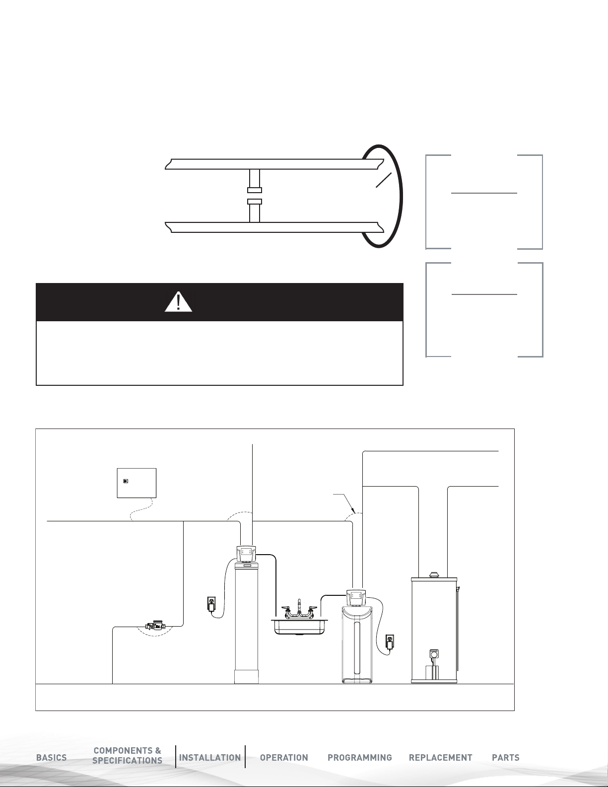
ELECTRICAL GROUNDING
An approved grounding
strap must be used in all
cases where metal pipe was
originally used and is later
interrupted by poly pipe,
the Noryl bypass valve or
by physical separation. The
grounding clamp used for
continuity, must be no less
than #6 copper conductor
to maintain proper metallic
pipe bonding.
8QILOWHUHG:DWHU%\SDVV
/RRS&XW&DSSHG
)LOWHUHG:DWHU/LQHLQ+RPH
*URXQG6WUDS5HTXLUHG%HFDXVH
RI%UHDNLQ&RQWLQXLW\
NOTE
Check your local
electrical code for
the correct strap.
NOTE
CAUTION
The ground from the electrical panel or breaker box to the water meter or underground
copper pipe is tied to the copper water lines. If these lines are cut during installation
of the Noryl bypass valve and/or poly pipe, an approved grounding strap must be used
between the two lines that have been cut. This will maintain continuity. The length of the
grounding strap will depend upon the number of units being installed and/or the amount
FIGURE 1A: TASTE AND ODOR FILTER (TO)
TYPICAL INSTALLATION:
Raw Water
To Outdoors
of copper pipe being replaced with plastic pipe. See drawing below.
Hard
Electrical Panel
Filtered
Water
Ground Strap
Drain
Drain
You must follow all
government codes and
regulations governing
the installation of
these devices.
Cold Soft Water
Hard Soft Water
Water Meter
Taste and Odor
(TO) Filter
Softener
Water Heater
11

FIGURE 1B: BIRM (BM) TYPICAL INSTALLATION:
Raw Water
To Outdoors
Electrical Panel
Water Meter
Birm
(BM) Filter
Hard
Filtered
Water
Drain
Ground Strap
Drain
Softener
Cold Soft Water
Hard Soft Water
Water Heater
FIGURE 1C: MULTI MEDIA FILTER (MM OR NEXSAND) TYPICAL INSTALLATION:
Raw Water
To Outdoors
Electrical Panel
Water Meter
Hard
Filtered
Water
Ground Strap
Drain
Drain
Cold Soft Water
Hard Soft Water
12
Multi Media
Filter (MM or nextSand)
Taste and Odor
(TO) Filter
Softener
Water Heater
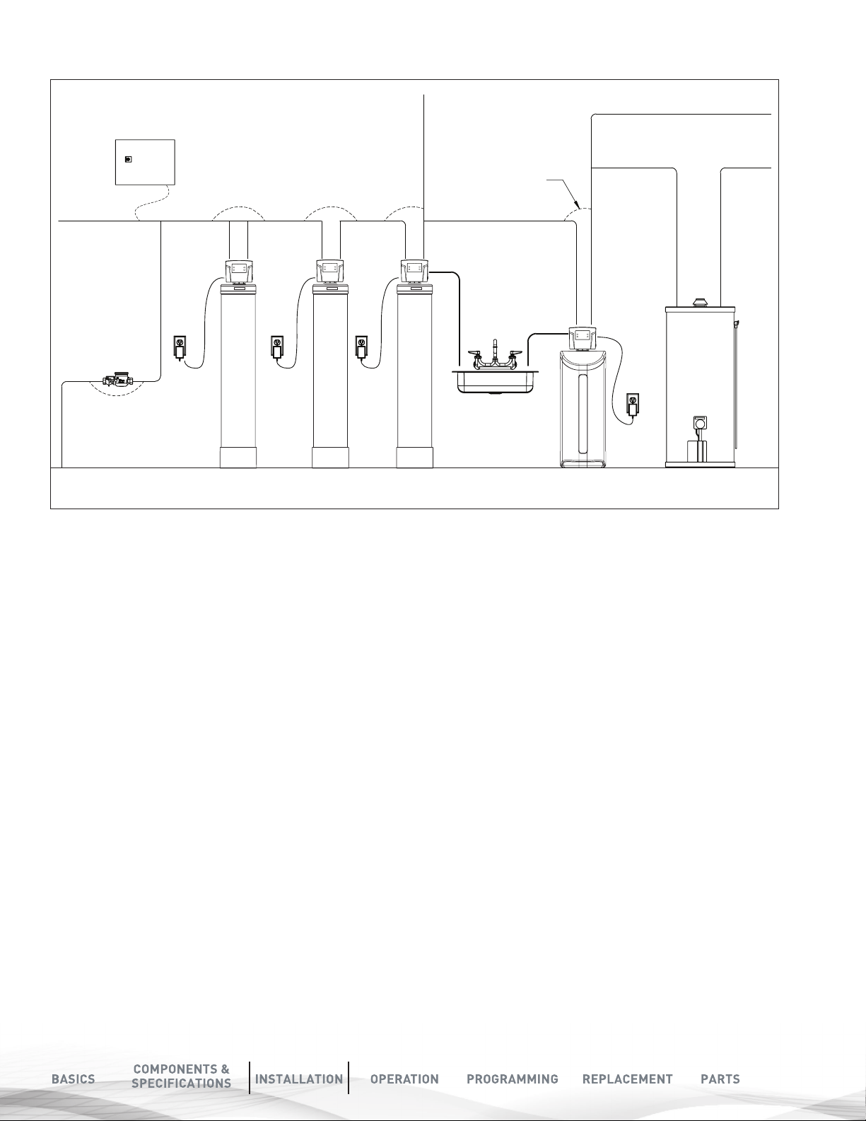
FIGURE 1D: NEUTRALIZING FILTER (NF) TYPICAL INSTALLATION:
Raw Water
To Outdoors
Water Meter
Electrical Panel
Multi Media
Filter (MM or neXtSand)
Multi Media
Filter (NU)
Hard
Filtered
Water
Drain
Taste and Odor
(TO) Filter
Ground Strap
Drain
Softener
Cold Soft Water
Hard Soft Water
Water Heater
13

TOOLS REQUIRED FOR
CHECK WATER
INSTALLATION:
Two adjustable wrenches
Additional tools may be required if modifications to home
plumbing are required.
Plastic inlet and outlet fittings are included with the softener. 3/4”
or 1” pipes to and from the softener fittings are recommended to
maintain full valve flow. You should maintain the same or larger
water supply pipe sizes as the softener inlet and outlet pipe sizes.
Use copper, brass, or PEX pipe and fittings.
Some codes may also allow PVC plastic pipe. Refer to local codes.
ALWAYS INSTALL THE INCLUDED BYPASS VALVE, OR 3 SHUT-OFF
VALVES. Bypass valves let you turn off water to the softener for
repairs, but still have water in the house pipes.
5/8” OD drain line is needed for the valve drain. A 10’ length of
hose is not included with some brands
NOTE
If the plumbing system is used as the ground leg of
the electric supply, continuity should be maintained
by installing ground straps around any nonconductive
plastic piping used in installation.
PRESSURE AND
PUMPING RATE
Two water system conditions must be checked carefully
to avoid unsatisfactory operation or equipment damage:
1. Minimum water pressure required at the softener
tank inlet is 30 psi.
2. The pumping rate of your home’s well pump must at
least equal to the required backwash flow rate of your
model (see Specifications on Page 6 for backwash
flow rates).
TO MEASURE THE PUMPING RATE OF YOUR
PUMP, FOLLOW THESE INSTRUCTIONS:
A. Determine the cycle time. Make certain no water is
being drawn. Open spigot nearest pressure tank.
When pump starts, close spigot and measure time (in
seconds) to refill pressure tank (when pump shuts
off). This figure represents cycle time.
B. Determine drawn-down time. With the pressure tank
full, draw water into a container of known volume and
measure the number of gallons drawn until the pump
starts again. This is draw-down.
C. Determine drawn cycle time. Divide the draw down
time by cycle time and multiply the result by
60 to arrive at the pumping rate in gallons per
minute (gpm).
DETERMINE THE CORRECT
LOCATION OF THE WATER
CONDITIONING EQUIPMENT
Determine the best location for your water softener, bearing in mind the
location of your water supply lines, drain line and 120 volt AC electrical
outlet. Subjecting the softener to freezing or temperatures above 43°C
(110°F) will void the warranty. Review the various conditions below to
determine a proper location:
1. Locate as close as possible to the water supply source.
2. Locate as close as possible to a floor or laundry tub drain.
3. Locate in correct relationship to other water conditioning
equipment (see Fig. 1 on Page 10)
4. Softener should be located in the supply line before the water heater.
Temperatures above 120°F damage softeners.
5. Do not install a softener in a location where freezing temperatures
occur. Freezing may cause permanent damage to this type of
equipment and will void the factory warranty.
6. Allow sufficient space around the unit for easy servicing.
7. Determine if additional plumbing is required if your water source is a
community water supply, a public water supply or you wish to bypass
water used for a geothermal heat pump, lawn sprinkling,
out-buildings or other high demand applications, refer to Fig. 1.
8. Keep the softener out of direct sunlight. Heat build up from direct
sunlight may soften and distort plastic parts.
To aid in your calculation, insert the data in the
following formula:
DRAW-DOWN________ (gals)
÷ CYCLE TIME______________x 60 (seconds)
= PUMPING RATE______________ (gpm)
EXAMPLE:
DRAWDOWN is 6 gals; CYCLE TIME is 53 secs; then,
PUMPING RATE equals: 6 gals ÷ 53 secs x 60 = 6.8 gpm
SEE SPECIFICATIONS ON PAGE 6
FOR MINIMUM FLOW RATES.
.
NOTE
If there is a severe loss in water pressure when the
softener unit is initially placed in service, the softener
tank may have been laid on its side during transit. If this
occurs, backwash the softener to “reclassify” the media.
14
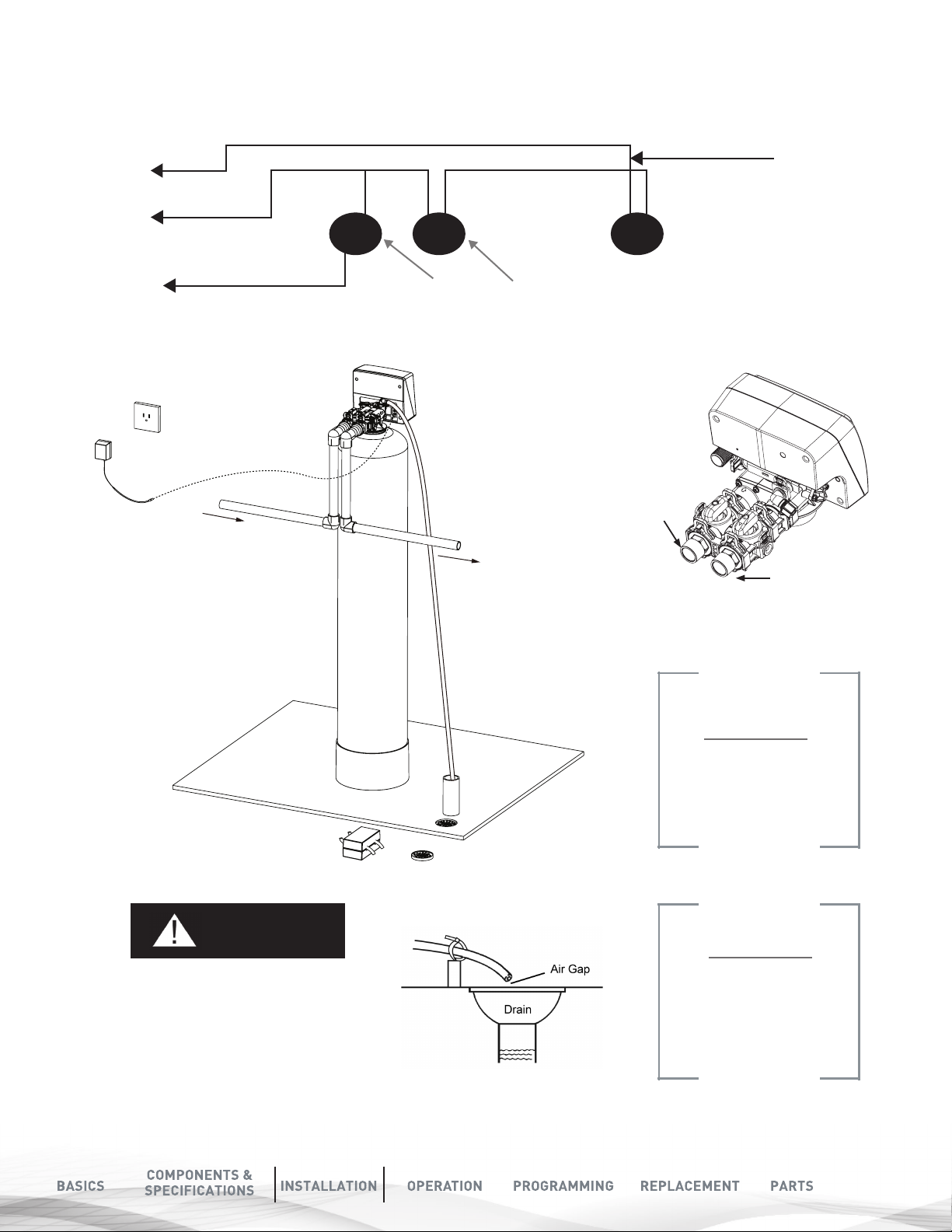
2XWOHW
,QOHW
tI
T
FILTER INSTALLATION
Cold (Raw water)
o Outside Faucet
Cold (Soft Water)
Cold (Filtered water)
InIn Ou
Cold (Raw water)
nOut
Filter
Hot (Soft Water)
Out
Water Heater
Water Softener
Inlet
Outlet
Opposite Most
Standard Softeners
NOTE
The valves are labeled
inlet and outlet on the
vale. Please make sure
to plumb as shown here
CAUTION
Never insert the drain line directly
into a drain, sewer line, or trap.
Always allow an air gap between
the drain line and the wastewater.
This will prevent the possibility of
sewage being back-siphoned
into the conditioner.
NOTE
The waste connection or drain
outlet shall be designed and
constructed to provide an
air-gap to the sanitary waste
system of 2 pipe diameters or
1 inch (22 mm).
(whichever is larger)
15

MEDIA INSTALLATION
1. MEDIA INSTALLATION (WHEN NECESSARY).
Models 250 or 300 media are shipped with separate media in pails or
boxes. Models lower than 2 CF of media come loaded
with media and this step can be skipped for new installation.
NOTE
The 8”, 9” and 10: tank
media is pre-installed.
Go to Step 4
CAUTION
The unit should be
de-pressurized before
installing or replacing media
A) Remove cap to Pressure Tank
PLUG
THE
RISER
TUBE
B) Temporarily plug the open end of the riser tube. This
ensures that no resin or gravel falls down into the
distribution. The riser (distributor) remains inside the
tank seated in the depression at the bottom.
Plug tube with a tape. Remove after media is loaded.
THE RISER
(DISTRIBUTOR)
REMAINS
INSIDE THE
TANK SEATED
IN THE
DEPRESSION
AT THE
BOTTOM
C) Fill support bed first. The media will not always
spill down inside the tank and may need to be
swept inside.
The large funnel makes filling the tank easier and
neater. (Or an empty 1 gallon or 4 liter container
with the bottom cut out makes a good funnel.)
16

D) Fill tank one quarter full of water
to protect distribution during gravel
installation.
Place the media into the tank in the
order indicated above. Slowly and
carefully add the gravel support bed
and the filtration media leveling each
layer as it is placed into the tank.
Fill support bed (if supplied) first.
During the filling process, ensure the
distributor tube stays on the bottom of
the tank, reasonably centered. Remove
the tape from the distributor once
media is loaded. Whenever possible,
fill the tank outdoors to avoid problems
with dust. If filling indoors, a dust mask
should be worn.
NEUTRALIZING
FILTER (NF)
MEDIA BED
Calcium
Carbonate &
Magnesium Oxide
Mixed
(Grey / White)
Support Bed
(when supplied)
Fine, Medium
and/or Coarse
Gravel
MULTI MEDIA
FILTER (MMF)
MEDIA BED
Anthrafilt /
Anthracite
(Black)
Fine Sand
Fine Garnet
(Purple)
Coarse Garnet
(Purple)
Support Bed
(when supplied)
Fine, Medium
and/or Coarse
Gravel
2. MEDIA INSTALLATION
ACTIVATED
CARBON FILTER
(ACF) MEDIA
BED
Carbon
(Black)
Support Bed
(when supplied)
Fine, Medium
and/or Coarse
Gravel
Unscrew Spill Cap
D-Tube
Attach
Upper
Basket
BIRM FILTER
(BM) MEDIA
BED
Birm
(Black)
Support Bed
(when supplied)
Fine, Medium
and/or Coarse
Gravel
MULTI MEDIA FILTER
(MM OR NEXSAND)
MEDIA BED
Nexsand
(Black)
Support Bed
(when supplied)
Fine, Medium
and/or Coarse
Gravel
NOTE
Grease port O-rings using brush
(not included) or your finger
(Make sure to wear protective
gloves)
Some medias like those used in NU
Models are sacrificial and deplete faster
depending on inlet water conditions and
usage. The media replenishment is more
frequent in high water usage and more
acidic water cases. The dome hole models
are available and supplied in which the
dome hole is available for a quick addition
or replenishment of media in the tank.
Unplug the riser tube, carefully position the valve over it and turn the valve into the threads
in the fiberglass tank, tightening securely into tank. Note: Ensure that the internal O-ring in
the valve fits securely over the riser tube. Silicone grease (part # 92360) or other food grade
lubricant may be applied to the O-ring to ease installation of the riser tube.
17

Dome Hole Cap Dome Hole Cap
Removed
CAUTION
Make sure the O-Ring is free of
defects. Use silicone based lubrication
(part # 92360) if necessary.
The filter is now
charged with media.
NOTE
CAUTION
Make sure that the unit is
de-pressurized before
conducting this task.
DO NOT use petroleum based lubricants as they
will cause swelling of O-ring seals.
18

3. MEDIA INSTALLATION
Outside faucets used to water lawns and gardens should not
supply untreated water. A new water line is often required
to be connected to supply untreated water to the inlet of the
water filter and to the outside faucets.
(CARBON UNITS MODEL TO)
Open the inlet on the bypass valve slightly and very slowly allow
water to enter the unit. (If the water enters too quickly it will
push the media or carbon up into the control valve and get
plugged).
Cut the water line between where it enters the house and
before any lines that branch off to feed the hot water heater or
other fixtures in the house and as near the desired location of
the water filter as possible. Install a tee fitting on the feed end
of the cut pipe, and an elbow fitting on the other end. Install
piping from the tee to the inlet of the water filter and from
the elbow to the outlet of the filter. To sever the water lines
which branch off to feed any outside faucets, cut the branch
lines approximately two inches from the fitting on the main
water line. Install an elbow on the end of the pipe nearest the
outside faucet and a cap on the end connected to the existing
water line. Install piping from the tee installed on the inlet
line to the water filter to the elbow installed on the pipe to the
outside faucet. Following this procedure will result in all lines
in the house, with the exception of the outside faucets, but
including the water heater and therefore the hot water lines,
being supplied with treated water.
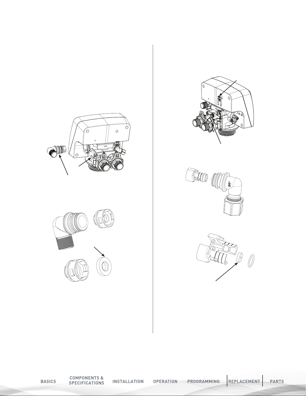
Make sure the bypass is attached well to the control valve.
Connect the straight or elbow connectors to the bypass with
red clips. Connect the inlet and outlet of the water filter to
the plumbing of the house. The control valve must not be
submitted to temperatures above 43°C (110°F). When sweat
fittings are used, to avoid damaging the control valve, solder
the threaded copper adaptors to the copper pipe and then,
using Teflon tape, screw the assembly into the bypass valve.
Do not use pipe thread compound as it may attack the
material
in the valve body.
Once the unit has filled sufficiently that water is at least equal to
the height of the top of the media shut down the water for 15 – 20
minutes for the carbon to soak. Unplug the power cable. After the
carbon has soaked for the recommended time continue by plugging
the power cable back in.
4b. (Other Models) Open the inlet on the bypass valve slowly and
allow water to enter the unit. (The outlet of the bypass should
remain closed to prevent any fines or debris from entering the
plumbing system. Allow all air to escape from the unit before
turning the water on fully then allow water to run to drain for 3-4
minutes.
5. Unplug the power cord from the power supply, open inlet. Check
the drain line flow. Allow the water to run for 30 minutes.
6. Plug in the valve and the valve will automatically advance to the
SERVICE position. Open the outlet valve on the bypass, then slowly
open the nearest treated water faucet and allow the water to run
until clear, close the tap and replace the faucet screen.
7. The Valve is already programmed from factory for AIO Models.
Please set up date and time of day as shown on next page.
Clips
Make sure both
brass and plastic
nuts are tightened
well
Inspect and check that the brine line plug is
Ensure that the brass and plastic nut connected
4. CONNECT DRAIN LINE:
A) Using plumbers tape, screw the 1/2” hose barb and attach
o-ring into the drain port in the valve.
B) Attach 1/2” drain hose to the hose barb. and tighten
securely with a hose clamp.
C) Run the drain line to a floor drain or a laundry drain.
Complete any necessary plumbing.
NOTICE
connected to the valve.
NOTICE
to the air check assembly is tight.
19

OPERATION
MENU
175/225/275
salt grid system
salt tank body
salt tank
lid
brine well and brine valve
STARTUP PROCEDURES
1. CONNECT THE TRANSFORMER TO THE VALVE.
Plug the 12-volt transformer into a 120 VAC 60 Hz outlet.
Power
Connector
2. ADD WATER TO BRINE TANK
Open the brine tank lid and add 3 gallons of water. Do not
add salt to the brine tank at this time.
3. SCREEN DISPLAY
When power is supplied to the
control, the screen will display
“INITIALIZING WAIT PLEASE”
while it finds the service position.
FAMILIARIZE WITH BUTTON
CONFIGURATION:
Date and Time
MENU
SET
KEY PAD CONFIGURATION
18-Apr-2016 10:35AM
Gal Remain 1400
Flow Rate 3 gpm/min
The controller will show the
following on the screen: Time,
Date and Gallons Remaining for
Regeneration
This function enters the basic set
up information required at the
MENU
time of installation.
This function accepts the values if
changed and advance to the next
SET
page in the menu
These buttons increase or decrease
the value of the settings while in the
programming mode.
System initializing
Please wait
4. SET THE VALUE TO MANUALLY REGENERATE
If screen is locked, press Menu Key for 5 seconds to unlock.
Manually Regenerate the Valve and move it
to backwash position. Press Menu Key and
Scroll down using Up and Down Arrow buttons
to “Manual Regen”. Press “SET” Select “Regen Now”
20
Skip this cycle by
pressing any key for 3
seconds
Complete
the Backwashing cycle to
let the air out of the
system
Date and Time
Hardness
Manual Regen.
Dealer Information
Main Menu
Regen. Now?
Regen. Tonight?
Press
To Cancel
To Conrm
Press
Brine Drawing
Any Key 3s To Next
13:59
Backwashing
Any Key 3S to Next
18%
18%
Rinsing
Any Key 3S to Next
Brine Rell
Any Key 3S to Next
18%
18%
Complete this cycle to
settle the media
Complete this cycle to let
the air out of the injector
system

SYSTEM DIAGNOSTICS
DURING REGENERATION
CHECK LIST
More than 90% of problems affecting the efficiency of
a softener system can be identified in 9 minutes or less. Follow
this diagnostic schedule below.
Start with Step 1, then follow each step in sequence to ensure
proper diagnostic procedures.
1. CHECK FOR PROPER INSTALLATION
A. Is the pipe from the pressure tank to the softener
unit attached to the inlet port of the control valve?
B. Is the pipe from the softener unit to the water heater
attached to the outlet port of the control valve?
C. Is the drain line of adequate diameter? Drain line
must be sized to prevent back pressure from
reducing backwash flow rate below minimum for the
model installed.
D. Has the drain line been “kinked”? A kinked drain line
must be replaced.
E. Is the drain line installed in a way that it will freeze in
cold weather?
F. If the system incorporates a standard air-to-water
pressure tank, does it have the required deep well air
volume control (air release valve) and is it functioning?
(Proper installation of this type of pressure tank should
have inlet from pump higher than outlet to service.)
NOTE
Typical examples of minimum drain line diameters are:
5/8” ID when drain is up to 15 ft from unit and backwash water
discharge point is slightly higher than the control valve
3/4” ID when drain is 25 ft away and/or drain is installed overhead
2. CHECK PH, IRON AND MANGANESE CONTENT
OF TREATED WATER
Is the treated water pH reading less than 6.7 (8.2 when
manganese is present)?
AUTOMATIC BYPASS
The regeneration cycle lasts approximately 60 minutes, after
which treated water service will be restored. During regeneration,
untreated water is automatically bypassed for use in the
household. Hot water should be used as little as possible during
this time to prevent hard water from filling the water heater.
IMPORTANT: This is why the automatic regeneration is set for
sometime during the night and manual regenerations should be
performed when little or no water will be used in the household.
NEW SOUNDS DURING REGENERATION
You may notice new sounds as your water softener operates.
The regeneration cycle lasts approximately 2-1/2 hours.
During this time, you may hear water running intermittently
to the drain.
PLUMBING SYSTEM
CLEAN-UP
The following procedures are guidelines only but have proven
successful in most instances. Under no circumstances should any
procedure outlined below be followed if contrary to the appliance
manufacturer’s instructions. Should there be any questions
concerning the advisability of performing a procedure, it is
strongly recommended your local BRITA®PRO dealer be
consulted prior to performing the procedure.
The plumbing system and water using appliances that have been
exposed, even for a short time, to iron-fouled water need to be
cleaned of the precipitated iron that has collected in them. If not
cleaned, the iron bleed (staining) will continue to be a problem.
Depending on the amount of iron in the water and the length of
time the water system has been exposed to iron fouling, select
from the following procedures those that apply to the type of
system and appliances that need to be cleaned to assure
iron-free water at the point of use.
If yes, replenish the media with MpH adder and check the
bed for “channelling”.
3. CHECK PUMPING RATE
Do not refer to a pumping rate curve for this data. Follow the
instructions found on Page 7. Is the measured pumping rate
less than the backwash rate of the softener? If yes, increase
the pumping rate by first reducing the system operating
pressure. If the pumping rate is still too low, replace the pump.
4. REVIEW OTHER USES OF WATER IN ADDITION
TO NORMAL DOMESTIC PURPOSES
(e.g. geothermal heating/cooling, swimming pool, lawn
irrigation, farm animal watering, etc.)
Have any high demand water uses been added subsequent
to the installation of the softener system or overlooked when
originally sizing the system? If a high demand situation exists,
resize the system using continuous service flow rate data.)
21

SOFTENER
1. Disconnect brine draw line from the brine cabinet. Place the loose end into a
five gallon plastic pail filled with a solution of warm water and 4 oz. of resin
mineral cleaner.
2. Manually advance control timer to brine draw position (refer to page 16
step 4 chart). Allow all the warm mineral cleaner solution to be drawn into
mineral bed.
Then immediately...
3. Close main water supply valve or turn power off to pump and proceed with
softener installation. During time required to install softener system,
iron- fouled softener resin will be chemically cleaned.
4. After softener installation is completed and final adjustments are made
with the water turned on and brine draw tube reconnected, manually
reprogram timer on softener to backwash setting. Allow timer to perform
an automatic regeneration cycle. During backwash of softener all iron
cleaned from the resin will be washed down the drain. It is advisable after
chemically cleaning softener to regenerate system twice to fully restore
capacity lost due to iron fouling.
WATER BYPASS
MANUAL BYPASS
In case of an emergency such as softener maintenance, you can isolate your
water softener from the water supply using the bypass valve located at the
back of the control.
In normal operation the bypass is open with the ON/OFF knobs in line with
the INLET and OUTLET pipes. To isolate the softener, simply rotate the knobs
clockwise (as indicated by the word BYPASS and arrow) until they lock.
You can use your water related fixtures and appliances as the water supply is
bypassing the softener. However, the water you use will be hard. To resume
treated service, open the bypass valve by rotating the knobs counterclockwise.
Please make sure bypass knobs are completely open otherwise the
unsoftened water could bypass through the valve.
Sample
Connection
SERVICE
BYPASS
BYPASS
Sample
Connection
OPERATING CONDITIONS
WATER HEATER
After completing the installation of the chemical free iron softener
system, clean the water heater by following these instructions:
1. Shut off energy supply to water heater and close heater inlet water
valve.
2. Drain hot water tank completely. Open inlet water valve allowing
heater tank to be refilled with conditioned water. Continue flushing
until water runs clear to drain.
3. If, after approximately 30 minutes flushing, water does NOT clear,
terminate flushing operation. Refill hot water heater with water and
pour approximately 1/2 gallon of household bleach into top of heater
tank. Allow bleach solution to stand in tank for 20 to 30 minutes.
Flush tank again until water is clear at drain. Turn energy supply on.
4. If the water heater has been exposed to both iron and hardness for a
long period of time, replacement of the heater tank may be the only
practical solution to prevent continued staining originating from this
source.
22
TOILET FLUSH TANKS
Prior to commencing installation of the Softener
system, pour 4 to 6 ounces of resin mineral cleaner
Pro-Rust Out or inhibited muriatic acid into flush tanks
and bowls and let stand. When installation is completed,
flush toilets several times with iron-free water. If iron
deposits or stains remain, repeat procedure until clear.
NOTE
If water does not become clear in approximately
10 minutes, water heater should probably
be replaced.

MAINTENANCE INSTRUCTIONS
Your chem free iron filter requires some minor maintenance to ensure optimum
performance and years of trouble-free clean water. The following steps should be
performed once or twice a year (more often under harsh conditions):
1. Verify the pumping rate of the system - do not refer to a
pumping curve for this data. Follow the instructions found
on page 7. If the measured pumping rate is less than the
backwash rate of the filter, see page 39, Trouble Shooting.
2. Have your water tested - for pH, iron and manganese on both
the treated and raw water to ensure your water conditions
haven’t changed.
3. Inspect the Control Valve and the piping between the iron filter
and the pressure tank to ensure they are not plugged with
raw iron. If the line becomes plugged, the flow of water to the
home will be reduced. This will result in a reduction of water
available for backwashing the unit which will inhibit operation
of the system.
4. Air-to-water pressure tank - periodically drain and flush your
tank to prevent a build-up of precipitated iron from forming in
the bottom of the tank.
5. Bladder tank - periodically check that the bladder air pressure
remains at 2 psi lower than the cut-in pressure of your pump.
6. For applications with low pH, manganese or hydrogen sulfide,
consult your local dealer for specific instructions to maintain
the efficiency and operation of your filter.
7. Periodic cleaning of the air vent assembly with mild acid
or vinegar will ensure that it continues to vent excess air
properly.
8. The filter tank can be cleaned with a mild soap solution.
9. Never subject the unit to freezing
REPLACING MEDIA BED
The media bed in a neutralizing Model NU filter is slowly
dissolved and has to be replaced. The frequency of replacement
varies, depending on water quality - consult your dealer to
determine the expected life of your media bed.
NU - the media bed in a neutralizing filter is slowly dissolved
and has to be replaced. The frequency of replacement varies,
depending on water quality - consult your dealer to determine
the expected life of your media bed.
TO - under normal operating conditions the effective life of the
filter media is approximately one to three years depending
on the water quality, after which, taste and odor problems
may return. When this happens contact your dealer for a
replacement media bed.
MM / Nexsand - under normal operating conditions, the media
should never need to be replaced. If you experience pressure
loss and cannot correct it with a manual regeneration, your
media bed may need replacing - contact your dealer.
BM - Depending on the raw water iron content.
CARE OF YOUR FILTER
To retain the attractive appearance of your new water filter,
clean occasionally with a mild soap solution. Do not use abrasive
cleaners, ammonia or solvents. Never subject your filter to
freezing or to temperatures above 43°C (110°F).
SERVICING COMPONENTS-
The seals and cartridge should be inspected/cleaned or
replaced every year depending on the inlet water quality
and water usage.
The media should be replenished or replaced depending
of inlet water quality and water consumption. Check with
your water treatment expert on the media bed change
frequency.
BELOW ARE SOME GUIDELINES:
Piston assembly, seal and spacers, injectors should be
replaced on an annual basis.
Please refer to the servicing section of this manual for step by
step procedure.
Not following the above will void all warranty on the control
valve.
Maintenance of your new water filter requires very little time
or effort but it is essential. Regular maintenance will ensure
many years of efficient and trouble free operation.
Maintenance Kit
(60010307)
23

BACKWASHING
TO CALCULATE BACK-
INSTRUCTIONS
TO CALCULATE BACKWASH FREQUENCY
- NORMAL APPLICATIONS
Backwash frequency for households with average water
use can be determined using the following guide. The guide
cannot be used if the filtered water supplies a swimming
pool, geothermal pump, outside spigots or other high water
demand devices or activities. If your application includes
any of the foregoing refer to the paragraph on “Special
Applications” below:
PEO-
PLE
IN
FAMI-
LY
1 1 1 1 1 1 1 1 1 1 1
2 1 1 1 1 1 2 2 2 2 2
3 1 1 1 2 2 2 3 3 3 3
4 1 1 2 2 2 3 3 4 4 4
5 1 1 2 2 3 3 4 4 6 6
6 1 2 2 3 3 4 6 6 6 6
1. Locate the box intersected by the number of people
in your family and the parts per million (ppm) of
iron in your water (if your ppm is between two
numbers on the guide, use the higher number).
2. The number in the box represents how many
times your filter has to backwash in a twelve day
schedule.
2 4 6 8 10 12 14 16 18 20
IRON CONTENT (PPM)
WASH FREQUENCY SPECIAL APPLICATIONS
To ensure adequate reserve capacity and prevent loss of
water pressure between backwashes the figure of 15,000 (not
the full 30,000 ppm capacity) is used to calculate backwash
frequency. Determine your backwash frequency as follows:
1. Estimate daily iron removal requirements using the
following calculation:
No. of people in family
x 75 gallons of water per person
+ No. of gallons of water for special use
= No. of gallons of water required per day
x Iron concentration (ppm)
= Daily iron removal requirements (ppm)
2. Establish backwash frequency using daily iron removal
requirements to complete the following calculation:
15,000 iron removal capacity (ppm)
÷ Daily iron removal requirements (ppm)
= No. of backwashes required in 12 day schedule
Example: You have four in the family, 8 ppm of iron and a
swimming pool requiring 46 gallons of water per day.
4 People in the family
x 75 Gallons of water per person
300 Gallons of water for family
+ 46 Gallons of water for the pool
346 Gallons of water required per day
x 8 Iron concentration
2,768 Daily iron removal requirements (ppm)
15,000 Iron removal capacity (ppm)
÷ 2,768 Daily iron removal requirements (ppm)
5.4 Backwash frequency (days)
The calculation indicates the need to backwash every 5.4
days. The control can only be programmed to backwash
at intervals of two, three, four, six and twelve days.
The control would be programmed to the closest more
frequent setting i.e. every four days.
24
CAUTION
Disassembly while under pressure can result
in flooding. Always follow these steps prior to
servicing the valve.
WARNING
Electrical shock Hazard!
unplug the unit before
removing the cover or
accessing any internal
control parts.
SERVICE THE PLATINUM VALVE
BEFORE SERVICING
1. Turn off water supply to conditioner :
A. If the conditioner installation has a 3 valve bypass system
first open the valve in the bypass line, then close the valves at the
conditioner inlet & outlet.
B. If the conditioner has an integral bypass valve, put it in the
bypass position.
C. If there is only a shut-off valve near the conditioner inlet, close it.
2. Relieve water pressure in the conditioner by stepping the control
into the backwash position momentarily. Return the control to the
In Service position.
3. Unplug electrical cord from outlet.
4. Disconnect drain line connection.

PROGRAMMING
MASTER PROGRAMMING
BELOW IS HOW THE SETTINGS ARE SET AT FACTORY:
PRESS MENU KEY
PRESS ‘+’ AND ‘-’ FOR 8 SECONDS
MODELS LANGUAGE REGION VALVE METER
BM-75 ENGLISH US GALLONS FILTER 1.364 DONT TOUCH OFF DAY S 10 10 12:00AM 3 DAYS #1 White 0 3.5 2S
BM-100 ENGLISH US GALLONS FILTER 1.364 DONT TOUCH OFF DAYS 10 10 12:00AM 3 DAYS #1 White 0 4.0 3S
BM-150 ENGLISH US GALLONS FILTER 1.364 DONT TOUCH OFF DAYS 10 10 12:00AM 3 DAYS #1 White 0 5.0 4S
BM-200 ENGLISH US GALLONS FILTER 1.364 DONT TOUCH OFF DAYS 10 10 12:00AM 3 DAYS #1 White 0 7.0 1
BM-300 ENGLISH US GALLONS FILTER 1.364 DONT TOUCH OFF DAYS 10 10 12:00AM 3 DAYS #1 White 0 10.0 2
MM-75 ENGLISH US GALLONS FILTER 1.364 DONT TOUCH OFF DAYS 10 10 12:00AM 3 DAYS #1 White 0 5.0 4S
MM-100 ENGLISH US GALLONS FILTER 1.364 DONT TOUCH OFF DAYS 10 10 12:00AM 3 DAYS #1 White 0 7.0 1
MM-150 ENGLISH US GALLONS FILTER 1.364 DONT TOUCH OFF DAYS 10 10 12:00AM 3 DAYS #1 White 0 10.0 2
MM-200 ENGLISH US GALLONS FILTER 1.364 DONT TOUCH OFF DAYS 10 10 12:00AM 3 DAYS #1 White 0 12.0 2
MM-300 ENGLISH US GALLONS FILTER 1.364 DONT TOUCH OFF DAYS 10 10 12:00AM 3 DAYS #1 White 0 15.0 3
NU-75 ENGLISH US GALLONS FILTER 1.364 DONT TOUCH OFF DAYS 10 10 12:00AM 3 DAYS #1 White 0 3.5 2S
NU-100 ENGLISH US GALLONS FILTER 1.364 DONT TOUCH OFF DAY S 10 10 12:00AM 3 DAYS #1 White 0 4.0 3S
NU-150 ENGLISH US GALLONS FILTER 1.364 DONT TOUCH OFF DAY S 10 10 12:00AM 3 DAYS #1 White 0 5.0 4S
NU-200 ENGLISH US GALLONS FILTER 1.364 DONT TOUCH OFF DAY S 10 10 12:00AM 3 DAYS #1 White 0 7.0 1
NU-300 ENGLISH US GALLONS FILTER 1.364 DONT TOUCH OFF DAY S 10 10 12:00AM 3 DAYS #1 White 0 10.0 2
TO-75 ENGLISH US GALLONS FILTER 1.364 DONT TOUCH OFF DAYS 10 10 12:00AM 3 DAYS #1 White 0 3.5 2S
TO-100 ENGLISH US GALLONS FILTER 1.364 DONT TOUCH OFF DAY S 10 10 12:00AM 3 DAYS #1 White 0 4.0 3S
TO-150 ENGLISH US GALLONS FILTER 1.364 DONT TOUCH OFF DAY S 10 10 12:00AM 3 DAYS #1 White 0 5.0 4S
TO-200 ENGLISH US GALLONS FILTER 1.364 DONT TOUCH OFF DAY S 10 10 12:00AM 3 DAYS #1 White 0 7.0 1
TO-300 ENGLISH US GALLONS FILTER 1.364 DONT TOUCH OFF DAY S 10 10 12:00AM 3 DAYS #1 White 0 10.0 2
NEX-75 ENGLISH US GALLONS FILTER 1.364 DONT TOUCH OFF DAYS 10 10 12:00AM 3 DAYS #1 White 0 5.0 4S
NEX-100 ENGLISH US GALLONS FILTER 1.364 DONT TOUCH OFF DAYS 10 10 12:00AM 3 DAYS #1 White 0 7.0 1
NEX-150 ENGLISH US GALLONS FILTER 1.364 DONT TOUCH OFF DAYS 10 10 12:00AM 3 DAYS #1 White 0 10.0 2
NEX-200 ENGLISH US GALLONS FILTER 1.364 DONT TOUCH OFF DAYS 10 10 12:00AM 3 DAYS #1 White 0 14.0 3
RATIO
SALT VS
EFFICIENCY
AUTO
CALCULA-
TION
REGEN.
MODE
BACK WASH
DURATION
RINSE
DURATION
AND SCROLL TO
‘MAIN MENU’. THEN
PRESS ‘SET’ TILL IT
BEEPS
REGEN
REGEN
TIME
SETTING
DAY
SETTING
Injector Injector
Color
VALVE SETTINGS
BLFC
Washer
DLFC
Washer
DLFC
Washer
Code
MENU
SET
Flow Rate: 24.5 GPM
18-Apr-2015 10:35AM
Days Remain 03
KEY PAD CONFIGURATION:
MENU - This function is to enter the basic
set up information required at the time of
installation.
SET/REGEN - This function is to accept the
values if changed and advance to the next
page in the menu.
to increase or decrease the value of the
settings while in the programming mode.
UP/DOWN - These buttons are used
25

STEP A - REGION SETTING
Press + and —. Hold until you hear a beep (8 seconds).
Press + or — to choose menu option. Press SETTINGS to enter.
Press + or — to change option. Press SETTINGS to accept.
STANDBY INTERFACE
= = Initial Setup interface = =
n
Language
n
Region
n
Valve
n
Meter Ratio
n
Salt vs Eciency Setting
n
Calculation
= Language =
n
English
Setting Complete
Press ¨ T o Return
= = Initial Setup interface = =
n
Language
n
Region
n
Valve
n
Meter Ratio
n
Salt vs Eciency Setting
n
Calculation
= Region =
n
U.S. Gallon
Setting Complete
Press ¨ To Return
STEP B - ADVANCED MENU
Press Menu key. Press — to advance to Advanced Menu
Press + or — to choose menu option. Press SET to enter
Press + or — to change option. Press SET to accept
Press Menu key. Press — to advance to Main Menu
Press SET or until you hear a beep.
Press — to advance to Advanced Menu
Press and hold SET 5 seconds or until you hear
= Main Menu =
Regen. Time Setting
System Capacity
Salt Mode Setting
Advanced Menu
= Advanced Menu =
Regen. Mode
Regen. Cycles
History Values
= Regen. Mode =
Calendar
Meter Immediate
Meter Delay
Meter Override
Setting Complete
Press To Return
a beep.
Press + or — to choose menu option. Press SET
to enter.
Press + or — to change option. Press SET to
accept.
= Advanced Menu =
Regen. Mode
Regen. Cycles
History Values
= Regen. Cycles =
Backwash Duration
Rinse Duration
= Backwash Duration =
10 Minutes
Press ¨ To Cancel
Press To Confirm
= Rinse Duration =
10 Minutes
Press To Cancel
Press To Confirm
Setting Complete
Press To Return
= = Initial Setup interface = =
n
Language
n
Region
n
Valve
n
Meter Ratio
n
Salt vs Eciency Setting
n
Calculation
= Valve Setting =
n
Filter
n
DownFlow
n
UpFlow
Setting Complete
Press ¨ To Return
= = Initial Setup interface = =
n
Language
n
Region
n
Valve
n
Meter Ratio
n
Salt vs Eciency Setting
n
Calculation
Meter Ratio
1.364
Press ¨ To Cancel
PressnTo Conrm
Setting Complete
Press ¨ To Return
= = Initial Setup interface = =
n
Language
n
Region
n
Valve
n
Meter Ratio
n
Salt vs Eciency Setting
n
Calculation
= Salt Vs Eciency =
Don’t Touch
n
E: 03.0 lbs Vs 5000 Grs
n
S: 06.0 lbs Vs 4150 Grs
n
H: 12.0 lbs Vs 2500 Grs
Setting Complete
Press ¨ To Return
STEP C - MAIN MENU
Press Menu key. Press — to advance to Advanced Menu
Press SET or until you hear a beep
Press + or — to choose menu option. Press SET to enter
Press + or — to change option. Press SET to accept
Date and Time
Hardness
Manual Regen.
Dealer Information
Main Menu
= Main Menu =
Regen. Time Setting
Regen. Days Setting
Advanced Menu
= = Regen. Time = =
12:00 AM
Press To Cancel
Press To Confirm
Setting Complete
Press ¨ To Return
Main Menu
Regen. Time Setting
Regen. Day Setting
Advanced Menu
= Main Menu =
Regen. Time Setting
Regen. Days Setting
Advanced Menu
= = Regen. Day = =
03 Days
Press ¨ To Cancel
Press To Confirm
Setting Complete
Press ¨ To Return
STEP D - USER SETTING
Press Menu key
Press SET or until you hear a beep
Press + or — to choose menu option. Press SET to enter
Press + or — to change value. Press SET to accept
Standby
Interface
Date and Time
Manual Regen.
Dealer Information
Main Menu
Date and Time
Manual Regen.
Dealer Information
Main Menu
= = Initial Setup interface = =
n
Language
n
Region
n
Valve
n
Meter Ratio
n
Salt vs Eciency Setting
n
Calculation
== Auto Calculation ==
ON OFF
Press ¨ To Cancel
PressnTo Conrm
Setting Complete
Press ¨ To Return
26
= = Date and Time = =
17 - Feb - 2016
12:25PM
Press To Cancel
Press To Confirm
Setting Complete
Press ¨ To Return
= = Dealer Informa-
tion = =
Quality Water
666 3 Ave
Chicago IL
Tel 12345678
Press To Cancel
Press To Confirm
Setting Complete
Press ¨ To Return

DIAGNOSTIC SCREEN
PRESS “MENU” KEY AND SCROLL TO “MAIN MENU”. THEN PRESS “SET” TILL IT
BEEPS. SCROLL TO ADVANCED MENU
Press “Menu” key . Press - to advance to Main Menu
Press “SET”
or until you hear a beep.
Press - to advance to Advanced Menu
Press and hold “SET” 5 seconds or until you hear a beep.
= Advanced Menu =
Resin Volume
Rell Rate
Regen. Mode
Backwash Override
Emergency Regen.
Regen. Cycles
History Values
= History Values =
General Diagnostics
Reserve
Usage History
Last Regen. On:
17-Feb-2016, 02:00AM
Used Since Regen.
0051 Gallons
Current Flow Rate:
15.22 gpm
Used Since Regen.
85.22 gpm
Peak Flow Rate on:
17-Feb-2016, 12:25PM
Software Version
1.10
= History Values =
General Diagnostics
Reserve
Usage History
Sunday: 5800 Gal
Monday: 5801 Gal
Tuesday: 5802 Gal
Wednesday: 5803 Gal
Thursday: 5804 Gal
Friday: 5805 Gal
Saturday: 5806 Gal
Highest record in
last 4 weekdays
Press - to advance to History Values
Press“SET”
Press “+” or “-”
Press “+” or “-”
or until you hear a beep.
to choose menu option. Press “SET”
to change option. Press “SET” to accept.
PARAMETER DESCRIPTION
LAST REGEN ONDate of last system
USED SINCE
REGEN
CURRENT
FLOW RATE
PEAK FLOW
= History Values =
General Diagnostics
Reserve
Usage History
RATE
SOFTWARE
VERSION
RESERVE The calculated reserve
28 DAYS
HISTORY
USAGE
HISTORY
TOTAL USED The total volume used.
TOTAL REGENS The total quantity of
TOTAL DAYS The total days in operation.
to enter.
regeneration.
Volume used since last
regeneration.
The current system
flow rate.
The peak or highest flow
rate since last regeneration.
The software version
programmed on the PCB.
for each day based on the
highest days usage over the
past 4 weeks.
The volume used for each
of the last 28 days.
The usage since system
start up and from the last
reset.
regenerations.
= 28 Days Reset =
NO YES
Press To Cancel
To Conrm
Press
= 28 Days History =
Sun Dec 01: 5800 Gal
Mon Dec 02: 5801 Gal
Sat Dec 28: 5806 Gal
= Usage History =
28 Days History
History Since Startup
History Since Reset
= 28 Days Reset =
NO YES
Press To Cancel
To Conrm
Press
= 28 Days Reset =
Reset Conrm?
Press To Cancel
Press
To Conrm
= 28 Days History =
Sun Dec 01: 5800 Gal
Mon Dec 02: 5801 Gal
Sat Dec 28: 5806 Gal
Page by page
display
= Usage History =
28 Days History
History Since Startup
History Since Reset
= History Since Startup =
Peak Flow Rate:
85.22 gpm
Total Used:
123456789 Gallons
Total Regen.s:
0088
Total Days:
0325
= Usage History =
28 Days History
History Since Startup
History Since Reset
= History Since Reset =
Peak Flow Rate:
85.22 gpm
Total Used:
123456789 Gallons
Untreated water:
2123456 Gallons
Total Regen.s:
0088
Total Days:
0325
Conrm and return
One by One
= History Since Reset =
Reset Conrm?
Press To Cancel
To Conrm
Press
27

REPLACEMENT
REPLACE PISTON AND/OR BRINE VALVE ASSEMBLY
Remove 4 X
Screws
1. Follow steps 1 to 6 of
timer /Powerhead replacement.
2. Remove four screws from the plate
on the valve body.
Plate
Brine Valve
Assembly
3. Remove the plate from the valve body and
pull the Piston Assembly from the valve.
The brine valve assembly can also be
removed in this stage.
4. Remove the seal spacer assembly,
grease it with silicone lubricant and
put back in.
Piston
Assembly
5. Replace piston assembly followed
by timer assembly.
6. Replace the piston
assembly and reverse
following steps
in this section
Seal and
Spacer
CLEAN INJECTOR ASSEMBLY
1.
Injector
Cap
2X Screws
4.
3.
Screen
5.
2.
Injector
Assembly
Gasket
1.
Remove the two screws from the
injector cap
2. Pull the injector cap and gasket
3. Pull the injector assembly
and screen
4. Replace/clean screen and injector
assembly and put it back in the valve
in appropriate location as shown
5. Put back the injector cap. Grease the
injector assembly o-rings and injector
cap gasket. Care should be taken to
put all o-rings and gaskets in place
and grease them so that they
don’t pinch
28

REPLACE TIMER
Meter Cable
1. Disconnect the meter cable from the
meter. (If flow meter is attached)
Piston Screw 2 X Screws from Powerhead
Washer
4 X Screws
2. Remove four screws from the back of
the valve cover
Front Cover
3. Remove the front cover of the valve.
Powerhead
Assembly
4. Remove the piston screw and
washer from the piston rod.
REPLACE MOTOR
1. Remove Screws from the back of the valve
and pull the cover
2. Remove all connections from the
circuit board
3. Remove the two screws from the motor.
Remove the motor and watch for the pin
under the motor.
4. Replace the motor, connections and cover
5. Remove the two screws from the powerhead as shown
6. Life the powerhead from the valve body assembly
7. Replace the powerhead by reverse following the steps in this section
1.
Cover 4X Screws
3.
4.
Front Cover
2.
Valve Body
Assembly
2X Screws
Motor
29

REPLACE METER ASSEMBLY
1.
Meter
Cable
2.
2X Clips
3.
Coupling Adaptor
5.
4.
1. Disconnect the meter cable from the meter.
2. Disconnect the valve from bypass by removing clips
3. Remove the coupling adaptor from the valve
4. Remove the meter support and then the impeller out from
the coupling and clean it
5. Replace meter with the help of special tool and
re-assemble the removed components back in the section
30

DISPLAY
REPLACE
REPLACEMENT
MICROSWITCHES
1.
4X Screws
3.
2X Screws
1. Remove Screws from the back of the valve
and pull the cover
2. Remove all connections from the circuit board
3. Remove the two screws from the microswitch
4. Replace the microswitch, connections and cover
2.
4.
Front Cover
Microswitches
1. Remove the screws from the back of the valve and
pull the front cover
2. Remove all connections from the circuit board
3. Remove the four screws from the
circuit board and pull it out
AFTER SERVICING
1. Reconnect drain line
2. Return bypass or inlet valve to normal in service
position. Water pressure will automatically build
in the softener
3. Check for leaks at all sealed areas. Check drain seal
with the control in the backwash position
4. Plug electrical cord into outlet
5. Set Time of Day and cycle the control valve manually to
assure proper function. Make sure control valve is
returned to the In Service position
NOTE
Be sure to shut off any bypass line.
31
REPLACE DRAIN
REPLACE BRINE LINE
LINE FLOW
CONTROL
1.
Clip
Drain Line Elbow
FLOW CONTROL
1.
Brine Line Elbow
2.
Clip
2.
Drain Line Washer
1. Pull the drain line clip and remove the
drain line elbow and washer
2. Clean/replace drain line washer
Brine Line Washer
1. Pull the brine line clip and remove
the brine line elbow and washer
2. Clean/replace brine line washer
32

PARTS
PLATINUM FILTER PARTS LIST
Upper Cone
(18280)
Bypass
60010004
Distributor
Control Valve
SYSTEM
MODEL
TP-75 8 x 44 25010025 25010027 25010026 50010005 10010043 95401
TO-100 9 x 48 25010034 25010036 25010035 50010005 10010043 95402
TO-150 10 x 54 25010049 25010051 25010050 50010005 10010043 95403
TO-200 12 x 52 25010058 25010060 25010059 50010005 10010043 95404
TO-300 14 x 65 25030001 and 50040039 Not Available Not Available 50010010 10010043 XXXXx
TO-400 16 x 65 25030002 ad 50040039 Not Available Not Available 50010010 10010043 XXXXX
NU-75 8 x 44 25010025 25010027 25010026 50010005 10010043 93500
NU-100 9 x 48 25010034 25010036 25010035 50010005 10010043 93501
NU-150 10 x 54 25010049 25010051 25010050 50010005 10010043 93502
NU-200 12 x 52 25010058 25010060 25010059 50010005 10010043 93503
NU-300 14 x 65 25030001 and 50040039 Not Available Not Available 50010010 10010043 xxxxx
NU-400 16 x 65 25030002 and 50040039 Not Available Not Available 50010010 10010043 xxxxx
MM-75 8 x 44 25010025 25010027 25010026 50010005 10010043 95418
MM-100 9 x 48 25010034 25010036 25010035 50010005 10010043 95415
MM-150 10 x 54 25010049 25010051 25010050 50010005 10010043 95416
MM-200 12 x 52 25010058 25010060 25010059 50010005 10010043 95417
MM-300 14 x 65 25030001 and 50040039 Not Available Not Available 50010010 10010043 XXXXX
MM-400 16 x 65 25030002 and 50040039 Not Available Not Available 50010010 10010043 XXXXX
BM-75 8 x 44 25010025 25010027 25010026 50010005 10010043 95435
BM-100 9 x 48 25010034 25010036 25010035 50010005 10010043 95449
BM-150 10 x 54 25010049 25010051 25010050 50010005 10010043 95436
BM-200 12 x 52 25010058 25010060 25010059 50010005 10010043 95437
BM-300 14 x 65 25030001 and 50040039 Not Available Not Available 50010010 10010043 95438
BM-400 16 x 65 25030002 and 50040039 Not Available Not Available 50010010 10010043 XXXXX
Nexsand-758 x 44 25010025 25010027 25010026 50010005 10010043 95632
MINERAL
TANK SIZE
TANK # TANK #
(BLACK
COLOR)
TANK #
(BLUE
COLOR)
DISTRIBUTOR #
VALVE # MEDIA
BED #
Nexsand-
100
Nexsand-
150
Nexsand-
200
Nexsand-
300
Nexsand-
400
9 x 48 25010034 25010036 25010035 50010005 10010043 95633
10 x 54 25010049 25010051 25010050 50010005 10010043 95644
12 x 52 25010058 25010060 25010059 50010005 10010043 95645
14 x 65 25030001 and 50040039 Not Available Not Available 50010010 10010043 XXXXX
16 x 65 25030002 and 50040039 Not Available Not Available 50010010 10010043 XXXXX
33

CONTROLLER ASSEMBLY PARTS LIST
%
%
%
%
%
NO. PART # PART DESCRIPTION QTY
B29 DNR Micro Switch Cable 1
B28 60010115 Meter Cable 1
B27 60010124 Power Cable 1
B26 60095092 Meter Cable Clip 1
B25 60095091 Power Cable Clip 1
B24 92393 Motor 12VAC 3W 1
B23 60010574 Screw on Mounting Plate 8
B22 60010573 Mounting Plate 1
B21 60010660 Motor Pin 1
B20 60010099 Screw on Main Gear 1
B19 60010100 Washer on Main Gear 1
B18 92391 Main Gear 1
B17 92389 Drive Gear 1
B16 DNR Screw on Back Cover 4
B15 DNR Washers on Screw 4
B14 DNR Platinum Back Cover 1
B13 92392 Brine Gear 1
B12 60010577 Locating wheel(UF) 1
B11 60010661 Washer on Locating Wheel 1
B10 DNR Screw 2.2×13 1
B9 60010575 Screw on Locating Wheel 1
B8 60010580 Micro Switch 2
B7 60010579 Screws on Micro Switch 2
B6 DNR Platinum Front Cover 1
B5 60010572 Screws on PCB 4
B4 92388 Platinum PCB 1
B3 60010571 PCB Absorb Shock Foam 1
B2 DNR Platinum Controller Cover 1
B1 DNR Controller Touch Panel 1
34

STANDARD BYPASS ASSEMBLY PARTS LIST
NO. PART #
WATER GROUP
C14 DNR O-ring on Shaft Top 2
C13 DNR Platinum Bypass Shaft Seal 2
C12 60095614 O-ring on Shaft Bottom 2
C11 60010069 Secure Clip of Plug 2
C10 92387 Secure Clip Inlet and Oulet 2
C9 DNR Steel Retainer Ring 2
C8 60010252 Elbow 1“ NPT Inlet and Oulet 2
C7 60010592 Straight 1“ NPT Inlet and Oulet 2
C6 60010590 O-ring on Inlet
C5 DNR Platinum Bypass Body 1
C4 DNR O-ring on Plug 2
C3 60010209 Plug 2
C2 DNR Shaft of Platinum Bypass 2
C1 DNR Knob on Platinum Bypass 2
PART DESCRIPTION QTY
and Oulet Adaptor
4
35

STANDARD VALVE BODY ASSEMBLY PARTS LIST
$
$
$
$
NO. PA RT # PART DESCRIPTION QTY
A51 60010184 Brine Line Elbow Nut 1
A50 60010172 Brine Line Elbow 1
A49 60010044 O-ring of Brine Line Elbow 1
A48 60010188 O-ring of BLFC Holder 1
A47 60010173 BLFC Holder 2
A46 60010128 BLFC(0.2GPM)(Optional) 1
A45 DNR Brine Line Connector 1
A44 DNR O-ring of Brine Line Connector 1
A43 60010099 Screw on Valve Bottom Connector 2
A42 60010599 Valve Bottom Connector 1
A41 60010080 Distributor O-ring 1
A40 60010598 Central Pipe Adaptor 1
A39 60010597 O-ring of Central Pipe Adaptor 1
A38 60010077 Tank Mouth O-ring 1
A37 60010715 Screen Platinum Valve 1
A36 60010595 Injector Cover 1
A35 DNR O-ring of Injector Cover 1
A34 60010186 Big O-ring of Injector Holder 1
A33 Check Page 23 #0000 Black Injector Nozzle
A32 60010174 Injector Holder 1
A31 Check Page 23 #0000 Black Injector Throat
A30 60010187 Small O-ring of Injector Holder 1
A29 DNR Platinum Valve Body 1
A28 60010069 Secure Clip Brine Line 1
A27 DNR End Plug Retainer 1
A26 60010076 Valve Body Connect Screws 2
A25 60010075 End Plug Retainer Screws 3
A24 60010574 Screw 3.5×13 1
A23 92381 Brine Valve Injector Stem
A22 92382 Spacer-Platinum Valve 8
A21 Seal-Platinum Valve 5
A20 92384 UP Flow Piston-Platinum Valve 1
A19 Piston Retainer-Platinum Valve 1
A18 Piston Pin 1
A17 End Plug-Platinum Valve 1
A16 Piston Rod-Platinum Valve 1
A15 92384 Piston Assembly-
A14 Check Page 23 DLFC(2.4GPM)(Optional) 1
A13 60095694 DLFC Holder 1
A12 60010211 O-ring on Drain Elbow 1
A11 60010253 Drain Elbow 3/4” NPT 1
60010254 Drain Elbow 1” NPT 1
A10 60010227 Secure Clip of Drain Line 1
A9
60010585
A8 Adaptor Coupling 2
A7 Small O-ring of Adaptor Coupling 2
A6 92387 Adaptor Secure clip 2
A5 60010589 Platinum Valve Connector 1
A4 60010596 Screws of Valve Connector 8
A3 60010238 Impeller Assembly 1
A2 DNR Bush 2
A1 60010587 Impeller Holder 1
(Optional)
(Optional)
Assembly
Platinum Valve(UF)
Big O-ring of Adaptor Coupling 2
1
1
1
1
36

DLFC PART # FOR PLATINUM VALVE
NO. PART #
1 60095720 BNT95DLFC-0(4.0 GPM) 1
2 60010143 BNT95DLFC-1(7.0GPM) 1
3 60010144 BNT95DLFC-2(11.0GPM) 1
4 60010145 BNT95DLFC-3(14.0GPM) 1
5 60010146 BNT95DLFC-4(17.0GPM) 1
6 60010147 BNT95DLFC-5(21.0GPM) 1
7 60095692 BNT95DLFC-6(24.0GPM) 1
8 60095721 BNT95DLFC-1S(2.4GPM) 1
9 60095722 BNT95DLFC-2S(3.5GPM) 1
10 60095723 BNT95DLFC-3S(4.5GPM) 1
11 60010140 BNT95DLFC-4S(5.0GPM) 1
12 60095724 BNT95DLFC-5S(6.0GPM) 1
13 60095725 BNT95DLFC-6S(6.0GPM) 1
14 60010142 BNT95DLFC-7S(7.0GPM) 1
PART DESCRIPTION
QTY
BLFC PART # FOR PLATINUM VALVE
NO. PART #
1 60010128 BNT95BLFC (0.2 GPM) 1
2 12053 BNT95BLFC-1(2.0 GPM) 1
3 60010162 BNT95 BLFC-7(1.35 GPM) 1
PART DESCRIPTION
QTY
INJECTOR PART # FOR PLATINUM VALVE
NO. PART #
1 60010601 INJECTOR THROAT( BLACK 0000#) 1
2 60010602 INJECTOR NOZZLE( BLACK 0000#) 1
3 60010603 INJECTOR THROAT( GREY 000#) 1
4 60010604 INJECTOR NOZZLE( GREY 000#) 1
5 60010605 INJECTOR THROAT( PURPLE 00#) 1
6 60010606 INJECTOR NOZZLE ( PURPLE 00#) 1
7 60010607 INJECTOR THROAT( RED 0#) 1
8 60010608 INJECTOR NOZZLE( RED 0#) 1
9 60010609 INJECTOR THROAT ( WHITE 1#) 1
10 60010610 INJECTOR NOZZLE ( WHITE 1#) 1
11 60010611 INJECTOR THROAT( BLUE 2#) 1
12 60010612 INJECTOR NOZZLE( BLUE 2#) 1
13 60010613 INJECTOR THROAT( YELLOW 3#) 1
14 60010614 INJECTOR NOZZLE( YELLOW 3#) 1
PART DESCRIPTION
QTY
NO 10 AND
11 INJECTOR
PARTS APPLY
TO AIO MODELS
37

TROUBLE SHOOTING
GUIDE
PROBLEM CAUSE CORRECTION
1. FILTER BLEEDS TASTE
AND ODOR OR SEDIMENT
2. FILTER FAILS TO
REGENERATE
3. FILTER REGENERATES
EVERY DAY
4. LOSS OF WATER
PRESSURE
5. LOSS OF MEDIA THROUGH
DRAIN LINE
6. DRAIN FLOWS
CONTINUOUSLY
A. Bypass valve is open
B. Electrical service to unit has
been interrupted
C. Defective or stripped media bed
D. Quality of water has worsened
E. Filter capacity too small
F. Filter not backwashing enough
G. Excessive water usage - calendar clock models
A. Electrical service to unit has
been interrupted
B. Timer is defective
C. Power failure
D. Timer motor does not run
A. Faulty gear train A. Check the mechanical linkage on the timer control to elimi-
A. Iron or turbidity build-up in filter
B. Filter not regenerating often
enough
C. Not enough water volume or
pressure to backwash properly
A. Air in water system
B. Backwash rate too fast
A. Foreign material in control
B. Timer motor stopped or jammed
A. Close bypass valve
B. Assure permanent electrical service (check fuse, plug or
switch)
C. Replace media
D. Have water sample analyzed to determine any change
E. Replace with larger unit or add another filter
F. Be sure flow control is not clogged or drain line restricted.
Be sure water pressure has not dropped and that pump has
sufficient capacity
G. Increase frequency of regeneration. Make sure there are no
leaks in toilets or sinks
A. Assure permanent electrical service (check fuse, plug or
switch)
B. Replace timer
C. Reset time of day
D. Replace defective motor
nate possible binding in the gear train
A. Clean control and treat bed with Iron Out. Increase frequency
of regeneration
B. Increase frequency of regeneration
C. Correct water supply problem
A. Assure that well system has proper air eliminator control.
Check for dry well condition
B. Check drain flow control for proper flow rates
A. Remove piston assembly and inspect bore. Remove foreign
material and check control in various regeneration positions
B. Replace timer motor
38

THIS PAGE INTENTIONALLY
LEFT BLANK
39

THIS PAGE INTENTIONALLY
LEFT BLANK
40

PERFORMANCE DATA STATEMENT
This filtration system has been tested and certified according to NSF/ANSI Standard 42 by IAPMO for the
reduction of the substances listed below, as verified and substantiated by test data. The concentration of the
indicated substances in the water entering the system was reduced to a concentration less than or equal
to the permissible limit for the water leaving the system, as specified in NSF/ANSI Standard 42. Please see
warranty for manufacturer’s limited warranty. Please see installation instructions for internal operation and
maintenance requirements.
NSF/ANSI STANDARD 42 AESTHETIC EFFECTS
MODEL NUMBER: BPF89CB75TO BPF89CB100TO BPF89CB150TO BPF89CB200TO BPF89CB300TO
Flow Rate (GPM): 4.6 5.2 7.2 10.2 14.0
Capacity (Gallons): 50,000 66,000 100,000 133,000 200,000
Working Pressure: 20 - 125 psig
Operating Temperature: 34 - 100 F
Pressure Drop: 7.0 PSI
Reduction Claim: Chlorine, Taste & Odor
Influent Challenge Conc.: 2.0 mg/L
Reduction Requirement >/=50%
Actual Minimum Percent
Reduction:
Actual Average Percent
Reduction:
This system has been tested according to NSF/ANSI 42 for reduction of the substances listed above.
This concentration of the indicated substances in water entering the system was reduced to a concentration
less than or equal to the permissible limit for water leaving the system, as specified in NSF/ANSI 42.
Please Note: While testing was performed under standard laboratory conditions, actual performance may vary.
Laboratory test conditions: pH: 6.5-8.5, water temperature: 72°F / 23°C - 75°F / 24°C
Do not use with water that is microbiologically unsafe or of unknown quality without adequate disinfection
before or after the system.
95.88%
98.26%
Certified by IAPMO R&T to
NSF/ANSI 42 for Chlorine,
Taste and Odor Reduction.
41

PERFORMANCE DATA STATEMENT
This filtration system has been tested and certified according to NSF/ANSI Standard 42 by IAPMO for the
reduction of the substances listed below, as verified and substantiated by test data. The concentration of the
indicated substances in the water entering the system was reduced to a concentration less than or equal
to the permissible limit for the water leaving the system, as specified in NSF/ANSI Standard 42. Please see
warranty for manufacturer’s limited warranty. Please see installation instructions for internal operation and
maintenance requirements.
NSF/ANSI STANDARD 42 AESTHETIC EFFECTS
MODEL NUMBER: BPF89CBK75TOK BPF89CBK100TOK BPF89CBK150TOK BPF89CBK200TOK BPF89CBK300TOK
Flow Rate (GPM): 4.6 5.2 7.2 10.2 14.0
Capacity (Gallons): 50,000 66,000 100,000 133,000 200,000
Working Pressure: 20 - 125 psig
Operating Temperature: 34 - 100 F
Pressure Drop: 7.0 PSI
Reduction Claim: Chlorine, Taste & Odor
Influent Challenge Conc.: 2.0 mg/L
Reduction Requirement >/=50%
Actual Minimum Percent
Reduction:
Actual Average Percent
Reduction:
This system has been tested according to NSF/ANSI 42 for reduction of the substances listed above.
This concentration of the indicated substances in water entering the system was reduced to a concentration
less than or equal to the permissible limit for water leaving the system, as specified in NSF/ANSI 42.
Please Note: While testing was performed under standard laboratory conditions, actual performance may vary.
Laboratory test conditions: pH: 6.5-8.5, water temperature: 72°F / 23°C - 75°F / 24°C
Do not use with water that is microbiologically unsafe or of unknown quality without adequate disinfection
before or after the system.
95.88%
98.26%
42
Certified by IAPMO R&T to
NSF/ANSI 42 for Chlorine,
Taste and Odor Reduction.

PERFORMANCE DATA STATEMENT
This filtration system has been tested and certified according to NSF/ANSI Standard 42 by IAPMO for the
reduction of the substances listed below, as verified and substantiated by test data. The concentration of the
indicated substances in the water entering the system was reduced to a concentration less than or equal
to the permissible limit for the water leaving the system, as specified in NSF/ANSI Standard 42. Please see
warranty for manufacturer’s limited warranty. Please see installation instructions for internal operation and
maintenance requirements.
NSF/ANSI STANDARD 42 AESTHETIC EFFECTS
MODEL NUMBER: BPF89CATCB75TOC BPF89CATCB100TOC BPF89CATCB150TOC BPF89CATCB200TOC BPF89CATCB300TOC
Flow Rate (GPM): 4.6 5.8 7.2 10.3 14.1
Capacity (Gallons): 50,000 66,500 100,000 133,000 200,000
Working Pressure: 20 - 125 psig
Operating
Temperature:
Pressure Drop: 9.0 PSI
Reduction Claim: Chloramines, Chlorine, Taste & Odor
Influent Challenge
Conc.:
Reduction
Requirement
Actual Minimum
Percent Reduction:
Actual Average
Percent Reduction:
This system has been tested according to NSF/ANSI 42 for reduction of the substances listed above.
This concentration of the indicated substances in water entering the system was reduced to a concentration
less than or equal to the permissible limit for water leaving the system, as specified in NSF/ANSI 42.
Please Note: While testing was performed under standard laboratory conditions, actual performance may vary.
Laboratory test conditions: pH: 6.5-8.5, water temperature: 72°F / 23°C - 75°F / 24°C
34 - 100 F
2.0 mg/L
>/=50%
94.39%
96.82%
Do not use with water that is microbiologically unsafe or of unknown quality without adequate disinfection
before or after the system.
Certified by IAPMO R&T to NSF/ANSI 42
for Chloramine, Chlorine Taste and Odor Reduction.
43

PERFORMANCE DATA STATEMENT
This filtration system has been tested and certified according to NSF/ANSI Standard 42 by IAPMO for the
reduction of the substances listed below, as verified and substantiated by test data. The concentration of the
indicated substances in the water entering the system was reduced to a concentration less than or equal
to the permissible limit for the water leaving the system, as specified in NSF/ANSI Standard 42. Please see
warranty for manufacturer’s limited warranty. Please see installation instructions for internal operation and
maintenance requirements.
NSF/ANSI STANDARD 42 AESTHETIC EFFECTS
MODEL NUMBER: BPF89CATCBK75TOCK BPF89CATCBK100TOCK BPF89CATCBK150TOCK BPF89CATCBK200TOCK BPF89CATCBK300TOCK
Flow Rate (GPM): 4.6 5.8 7.2 10.3 14.1
Capacity (Gallons): 50,000 66,500 100,000 133,000 200,000
Working Pressure: 20 - 125 psig
Operating
Temperature:
Pressure Drop: 9.0 PSI
Reduction Claim: Chloramines, Chlorine, Taste & Odor
Influent Challenge
Conc.:
Reduction Requirement >/=50%
Actual Minimum
Percent Reduction:
Actual Average Percent
Reduction:
This system has been tested according to NSF/ANSI 42 for reduction of the substances listed above.
This concentration of the indicated substances in water entering the system was reduced to a concentration
less than or equal to the permissible limit for water leaving the system, as specified in NSF/ANSI 42.
Please Note: While testing was performed under standard laboratory conditions, actual performance may vary.
Laboratory test conditions: pH: 6.5-8.5, water temperature: 72°F / 23°C - 75°F / 24°C
34 - 100 F
2.0 mg/L
94.39%
96.82%
44
Do not use with water that is microbiologically unsafe or of unknown quality without adequate disinfection
before or after the system.
Certified by IAPMO R&T to NSF/ANSI 42
for Chloramine, Chlorine Taste and Odor Reduction.

PERFORMANCE DATA STATEMENT
This filtration system has been tested and certified according to NSF/ANSI Standard 42 by IAPMO for the
reduction of the substances listed below, as verified and substantiated by test data. The concentration of the
indicated substances in the water entering the system was reduced to a concentration less than or equal
to the permissible limit for the water leaving the system, as specified in NSF/ANSI Standard 42. Please see
warranty for manufacturer’s limited warranty. Please see installation instructions for internal operation and
maintenance requirements.
NSF/ANSI STANDARD 42 AESTHETIC EFFECTS
MODEL NUMBER: BPF89NEU75PH BPF89NEU100PH BPF89NEU150PH BPF89NEU200PH BPF89NEU300PH
Flow Rate (GPM): 4.6 5.8 7.2 10.2 14.0
Capacity (Gallons): 11,000 15,000 22,000 28,000 45,000
Working Pressure: 20 - 125 psig
Operating Temperature: 34 - 100 F
Pressure Drop: 9.0 PSI
Reduction Claim: Low pH Adjustment
Influent Challenge Conc.: 4 +/- 0.5
Reduction Requirement 6.5-8.5
Actual Minimum Percent
Reduction:
Actual Average Percent
Reduction:
Average Effluent pH: 7.04
This system has been tested according to NSF/ANSI 42 for reduction of the substances listed above.
This concentration of the indicated substances in water entering the system was reduced to a concentration
less than or equal to the permissible limit for water leaving the system, as specified in NSF/ANSI 42.
Please Note: While testing was performed under standard laboratory conditions, actual performance may vary.
Laboratory test conditions: pH: 6.5-8.5, water temperature: 72°F / 23°C - 75°F / 24°C
Do not use with water that is microbiologically unsafe or of unknown quality without adequate disinfection
before or after the system.
N/A
N/A
Certified by IAPMO R&T to NSF/ANSI 42
for low pH adjustment.
45

PERFORMANCE DATA STATEMENT
This filtration system has been tested and certified according to NSF/ANSI Standard 42 by IAPMO for the
reduction of the substances listed below, as verified and substantiated by test data. The concentration of the
indicated substances in the water entering the system was reduced to a concentration less than or equal
to the permissible limit for the water leaving the system, as specified in NSF/ANSI Standard 42. Please see
warranty for manufacturer’s limited warranty. Please see installation instructions for internal operation and
maintenance requirements.
NSF/ANSI STANDARD 42 AESTHETIC EFFECTS
MODEL NUMBER: BPF89NEX75TUR BPF89NEX100TUR BPF89NEX150TUR BPF89NEX200TUR
Flow Rate (GPM): 8.0 9.0 10.0 12.0
Capacity (Gallons): N/A
Working Pressure: 20 - 125 psig
Operating Temperature: 34 - 100 F
Pressure Drop: 9.0 PSI
Reduction Claim: Particulate Class V
Influent Challenge Conc.: 10,000 PPM
Reduction Requirement </=85%
Actual Minimum Percent
Reduction:
Actual Average Percent
Reduction:
Average Effluent pH: 7.04
This system has been tested according to NSF/ANSI 42 for reduction of the substances listed above.
This concentration of the indicated substances in water entering the system was reduced to a concentration
less than or equal to the permissible limit for water leaving the system, as specified in NSF/ANSI 42.
Please Note: While testing was performed under standard laboratory conditions, actual performance may vary.
Laboratory test conditions: pH: 6.5-8.5, water temperature: 72°F / 23°C - 75°F / 24°C
Do not use with water that is microbiologically unsafe or of unknown quality without adequate disinfection
before or after the system.
99.9%
>99.9%
46
Certified by IAPMO R&T to NSF/ANSI 42
for Particulate Class V reduction.

This limited warranty is solely provided to approved dealers of Brita® Pro Products
LIMITED WARRANTY
sold by Protect Plus Pro, LLC and is not applicable to consumers or homeowners.
Consumers and homeowners should contact the dealer they purchased their product
for warranty information.
Please find below a summary of warranty information for Brita® Pro Products.
PRODUCT WARRANTY:
Protect Plus Pro, LLC warrants only to its dealers that each product is free from defects
in materials and workmanship. The length and terms of the product warranties vary as
specifically set forth below.
A) LIMITED WARRANTY TABLE FOR ASSEMBLED UNITS
The following Table provides the warranty coverage for assembled units by Valve Type.
Control Valve Limited Control Valve Warranty Limited Pressure Tank Warranty Limited Brine Tank Warranty
Platinum Series 7 Years Limited Lifetime Limited Lifetime
Gold Series 7 Years Limited Lifetime Limited Lifetime
Silver Series 5 Years 10 Years 10 Years
NRV 5 Years 10 Years N/A
Diamond Series 5 Years 5 Years N/A
1) LIMITED SEVEN YEAR WARRANTY FOR CONTROL VALVE
AND LIMITED LIFETIME WARRANTY FOR MINERAL TANKS
AND BRINE TANKS (PLATINUM AND GOLD SYSTEMS):
Seven Year Limited Control Valve Warranty
Protect Plus Pro, LLC will replace the control valve of any new water conditioner
assembled unit which fails within 84 months from date of purchase or installation by
the approved dealer. This warranty does not cover control valves purchased or installed
separate and not part of a new, assembled unit.
Limited Lifetime Warranty on Mineral Tanks and Brine Tanks:
Protect Plus Pro, LLC will provide a replacement mineral tank or brine tank to any
approved dealer that purchased the new water conditioner assembled unit from Protect
Plus Pro, LLC and whose client is in possession of a tank that fails, provided that the
water conditioner is at all times operated in accordance with specifications, contained
within the owner’s manual, installed correctly, and not subject to freezing or negative
pressure vacuum.
Limitations To Limited Warranty:
Damage to any part of this water conditioner as a result of misuse, misapplication,
neglect, alteration, accident, installation or operation contrary to our printed
instructions, contained within the owner’s manual, damage to ion exchange resin
and seals caused by chlorine / chloramines in the water supply, or damage caused
by any force of nature is not covered in this warranty. DAMAGE TO PISTONS, SEALS,
AND OR SPACERS WITHIN THE CONTROL VALVE ARE NOT COVERED UNDER
THIS WARRANTY, IF THESE PARTS ARE EXPOSED TO HARSH ENVIRONMENTAL
CONDITIONS, SUCH AS HIGH LEVELS OF IRON, MANGANESE, SULPHUR, AND
SEDIMENT. We will repair or replace defective parts if our warranty department
determines it to be defective under the terms of this warranty. Protect Plus Pro, LLC
assumes no responsibility for consequential damage, labor or expense incurred as
a result of a defect or failure. Media and Resin coverage is limited to the warranty
provided by the original manufacturer. For a copy of this warranty, please contact
Protect Plus Pro, LLC.
2) LIMITED FIVE YEAR WARRANTY FOR CONTROL VALVE
(SILVER SYSTEM):
Five Year Limited Control Valve Warranty:
Protect Plus Pro, LLC will replace the control valve which fails within 60 months from
date of purchase or installation by the approved dealer This warranty does not cover
control valves purchased or installed separate and not part of a new, assembled unit.
47

3) LIMITED TEN YEAR WARRANTY FOR MINERAL TANKS AND
LIMITED WARRANTY
BRINE TANKS (SILVER SYSTEM AND NRV):
Protect Plus Pro, LLC will provide a replacement mineral tank or brine tank to any
approved dealer that purchased the new water conditioner assembled unit from
Protect Plus Pro, LLC and whose client is in possession of a tank that fails within 120
months, provided that the water conditioner is at all times operated in accordance with
specifications, contained within the owner’s manual, and not subject to freezing or
negative pressure vacuum.
Limitations To Limited Warranty: Damage to any part of this water conditioner as a
result of misuse, misapplication, neglect, alteration, accident, installation or operation
contrary to our printed instructions, contained within the owner’s manual, damage to ion
exchange resin and seals caused by chlorine / chloramines in the water supply, or damage
caused by any force of nature is not covered in this warranty. DAMAGE TO PISTONS,
SEALS, AND OR SPACERS WITHIN THE CONTROL VALVE ARE NOT COVERED UNDER THIS
WARRANTY, IF THESE PARTS ARE EXPOSED TO HARSH ENVIRONMENTAL CONDITIONS,
SUCH AS HIGH LEVELS OF IRON, MANGANESE, SULPHUR, AND SEDIMENT. We will
repair or replace defective parts if our warranty department determines it to be defective
under the terms of this warranty. Protect Plus Pro, LLC assumes no responsibility for
consequential damage, labor or expense incurred as a result of a defect or failure. Media
and Resin coverage is limited to the warranty provided by the original manufacturer. For a
copy of this warranty, please contact Protect Plus Pro, LLC.
B) LIMITED WARRANTY ON COMPONENT PARTS NOT
PURCHASES AS PART OF A NEW WATER CONDITIONER
ASSEMBLED UNIT
For Component parts not sold as a part of a new water conditioner assembled unit system
are warranted to do the work for which they are intended where properly installed and
operated. The new water conditioner assembled unit consists of a control valve, pressure
tank, and brine tank sold as a complete, assembled unit. For component parts not sold
as a new water conditioner assembled unit, Protect Plus Pro, LLC provides the following
limited warranty on the component parts:
48
48
1) FIBERGLASS TANKS- Protect Plus Pro, LLC will provide a replacement fiberglass
tank to any dealer whose client is in possession of a fiberglass tank that fails within
120 months, provided that the water conditioner is at all times operated in accordance
with specifications, contained within the owner’s manual, and not subject to freezing or
negative pressure vacuum;
2) CONTROL VALVE AND ASSOCIATED ELECTRONICS- Protect Plus Pro, LLC
will replace the control valve of any new water conditioner assembled unit which fails
within 60 months from date of purchase by the dealer or installation by the dealer;
3) BRINE TANKS AND RELATED ASSEMBLIES- Protect Plus Pro, LLC will
provide a replacement brine tank to any dealer whose client is in possession of
a brine tank that fails within 60 months, provided that the water conditioner is at
all times operated in accordance with specifications, contained within the owner’s
manual, and not subject to freezing or negative pressure vacuum;
4) MEDIA AND RESIN- Media and Resin coverage is limited to the warranty provided
by the original manufacturer. For a copy of this warranty, please contact Protect Plus
Pro, LLC; and
5) DAMAGE TO PISTONS, SEALS, AND OR SPACERS WITHIN THE CONTROL VALVE
ARE NOT COVERED UNDER THIS WARRANTY, IF THESE PARTS ARE EXPOSED TO HARSH
ENVIRONMENTAL CONDITIONS, SUCH AS HIGH LEVELS OF IRON, MANGANESE, SULPHUR,
AND SEDIMENT.
Protect Plus Pro, LLC only provides a limited warranty for this product to its approved
dealers. Protect Plus Pro, LLC does not provide any warranty to any consumer purchaser or
household purchaser of this product. The consumer purchaser or household purchaser
should consult the dealer they purchased this product from to determine the warranty, if any,
provided by the dealer.
 Loading...