

Brita Platinum Performance, BPF89CB75TO, BPF89CBK100TOK, BPF89CB300TO, BPF89CBK75TOK Installation Manual
...
PLATINUM
TASTE AND ODOR (TO)
MULTIMEDIA (MM)
FILTER
NEXSAND
NEUTRALIZER (NU)
BIRM (BM)
Professional
Installation
MANUAL
Version V1.0F
54565
THROUGHOUT YOUR HOME | THROUGHOUT YOUR LIFE
The Platinum Carbon Filter Series is certified by
IAPMO R&T to NSF/ANSI 42 for chlorine, taste
and odor reduction.
The Platinum Catalytic Carbon Filter Series
is certified by IAPMO R&T to NSF/ANSI 42 for
chloramine, chlorine taste and odor reduction.
The Platinum Neutralizer Filter Series is
certified by IAPMO R&T according to NSF/ANSI
42 for low pH adjustment.
The Platinum Nexsand Filter Series is certified
by IAPMO R&T to NSF/ANSI 42 for Particulate
Class V reduction.
2
2
This control value and pressure tank is Tested
and Certified by NSF International against
NSF/ANSI Standard 44 for material and
structural integrity requirements.
COMPONENT
828.449.2536
BRITA® PRO
www.britapro.com
BRITA®PRO trademark and logo are registered trademarks of Brita LP and are
used under license by Protect Plus, LLC. All rights reserved
420 3rd Avenue NW
Hickory, NC 28601

READ THIS PAGE FIRST
CONTENTS
BEFORE STARTING INSTALLATION 4
BASICS
HOW YOUR FILTER WORKS 5
COMPONENTS & SPECIFICATIONS
SPECIFICATIONS 6
INSTALLATION
UNPACK & INSTALL 8
CHECK VALVE SERIAL NUMBER & VALVE TYPE 10
PREINSTALLATION INSTRUCTIONS 11
ELECTRICAL GROUNDING 11
TOOLS REQUIRED FOR INSTALLATION 14
DETERMINING LOCATION 14
CHECK WATER PRESSURE AND PUMPING RATE 14
FILTER INSTALLATION 15
MEDIA INSTALLATION 16
OPERATION
STARTUP PROCEDURES 20
DIAGNOSTIC CHECKLIST 21
DURING REGENERATION 21
PLUMBING SYSTEM CLEANUP 21
SOFTENERWATER BYPASSOPERATING CONDITIONS 22
MAINTENANCE INSTRUCTIONS 23
BACKWASHING INSTRUCTIONS 24
CALCULATE BACKWASH FREQUENCY 24
SERVICE THE PLATINUM VALVE 24
PROGRAMMING
MASTER PROGRAMMING 25
DIAGNOSTIC SCREEN 27
REPLACEMENT
REPLACE PISTON &/OR BRINE VALVE 28
CLEAN INJECTOR ASSEMBLY 28
REPLACE TIMER 29
REPLACE MOTOR 29
REPLACE METER ASSEMBLY 30
DISPLAY REPLACEMENT 31
REPLACE MICROSWITCHES 31
AFTER SERVICING 31
DRAIN LINE FLOW CONTROL 32
BRINE LINE FLOW CONTROL 32
PARTS
FILTER 33
CONTROLLER ASSEMBLY PARTS LIST 34
STANDARD BYPASS ASSEMBLY PARTS LIST 35
STANDARD VALVE BODY ASSEMBLY PARTS LIST 36
TROUBLE SHOOTING GUIDE 38
PERFORMANCE DATA STATEMENT 41
WARRANTY 47
3
READ THIS
PAGE FIRST
BEFORE STARTING INSTALLATION
You must read and understand the contents of this manual
before installing or operating your water softener. Personal injury
or property damage could result if you fail to follow instructions in
this manual.
This system and its installation must comply with state and
local regulations. Check with your local public works department
for plumbing and sanitation codes. Local codes should be
followed In the event the codes conflict with any content in this
manual.
For installations in Massachusetts, Massachusetts Plumbing
Code 248 CMR shall be adhered to. Consult your licensed plumber
for installation of this system.
This water softener must be operated on pressures
between 30 psi to 125 psi. If the water pressure is higher than 125
PSI, use a pressure reducing valve in the water supply line to the
softener.
This unit must be operated at temperatures between 40°F and
110°F (4°C - 43°C).
Do not use this water softener on hot water supplies.
Do not install this unit where it may be exposed to wet
weather, direct sunlight, or temperatures outside of the
range specified above.
Apply provided NSF certified lubricant to all o-rings during
installation. Do not use pinched or damaged o-rings during
installation.
Softeners are exposed to high levels of iron, manganese,
sulfur, and sediments. Damage to pistons, seals, and or spacers
within the control valve are not covered in this warranty due to the
harsh environment.
It is recommended to annually inspect and service the control
valve. Frequent cleaning and or replacement of piston, seals,
and or spacers may be necessary depending on how harsh the
conditions are. An Annual Maintenance kit (Part # 60010307) is
available for this purpose.
Do not use water that is microbiologically unsafe without
adequate disinfection before or after this system.
This publication is based on information available when
approved for printing. Continuing design refinement could
cause changes that may not be included in this publication.
See page 8 for unpack and inspect system
BRITA®PRO reserves the right to change the specifications
referred to in this literature at any time, without prior notice.
4
INSTALL
NOTES &
SAFETY
MESSAGES
Watch for the
following messages
in this manual:
EXAMPLE:
NOTE
Check and comply with
your state and local
codes. You must follow
these guidelines.
EXAMPLE:
EXAMPLE:
CAUTION
Disassembly while under pressure
can result in flooding.
WARNING
ELECTRICAL SHOCK HAZARD! Unplug the unit before removing
the cover or accessing any internal control parts

BASICS
The success of the installation will depend, to a great
extent, on advanced planning and preparation. Careful
attention to the location of the unit, accessibility to
electrical and drain facilities, and the availability of the
proper tools will ensure a professional-looking installation.
Of utmost importance is the assurance that the filter has
been properly applied and meets all specifications.
APPLICATION:
Correct application is directly associated with the
performance and life expectancy of any water filter. It is
important, therefore, to understand how your Brita® Pro
Water Filter functions and to know its capabilities and
limitations so that a correct application can be made.
By following the guidelines and recommendations set forth
in this manual, you can be certain your filter is applied
correctly.
MM / NEXSAND FILTER
The Automatic Water Filter is capable of removing
particulate matter particle size as small as 30 microns.
It will not remove color, organics, colloidal turbidity or
dissolved solids. Some applications include:
- Removal of suspended matter in any water system
- Removal of particulate matter, such as clay, mud, etc.
- Prefiltration of oxidized iron prior to an automatic or
manual softener
-Removal of light sand
The quality and number of gallons of filtered water
between backwashes will depend upon the amount, type,
and size of the particulate matter being filtered. If a water
sample is sent to a laboratory, where application of a MMF
Type unit is contemplated. The laboratory will test for
Nephelometric Turbidity Units (NTU) and suspended solids
(mg/L). The sample will also be filtered through 10 micron
filter paper and NTU run on a filtered sample. If the NTU
of the raw water exceeds 150, suspended solids exceed
150 mg/L, or the filter water through the 10 micron filter
paper has unacceptable quality, a MMF filter might not
be applicable. As a guide, the U.S. Public Health Drinking
Water standards states the turbidity should not exceed
1 NTU. The exact number of gallons filtered between
backwashes can not be given because of many variables.
TO FILTER
Automatic Water Filter with Activated Media will control
chlorine taste and odor, and it will also remove most
objectional organic colors. It will not remove hydrogen
sulfide. It is important to note that whenever the cause
of an objectional taste or odor has not been established,
Health Authorities should determine if the water is safe
to drink. Do not use with water that is microbiologically
unsafe or of unknown quality without adequate disinfection
before or after the system.
NU FILTER*
Automatic Water Filter with Neutralizing Media will
neutralize slightly acid water (pH 5.2 to >6.8) and thus help
to prevent unsightly brown or green stains due to corrosion
of household plumbing. If the pH is between 5 and 6, one
part of Magnesium Oxide Media should be mixed with five
parts of Calcite Media to provide additional neutralizing
capability. If the water to be treated has a pH less than 5, a
high hardness, or a high carbon dioxide level, NF might not
be applicable; a solution feeder should be used. Because
NF adds hardness, it should be used prior to a softener.
BM FILTER
This media acts as a catalyst for the removal of iron and
manganese from the water but require pre-oxidation. This
media removes the iron and manganese from the water.
This is not recommended to remove hydrogen sulfide from
the water and requires high pH water. The media is not
sacrificial hence no replenishment is required.
NOTE
Under dynamic conditions it might be necessary to mix five parts
Calcite with one part Magnesium Oxide to effectively raise the pH.
In order to size and apply the equipment correctly, a complete
analysis of the water supply should be obtained.
5
COMPONENTS &
SPECIFICATIONS
TASTE & ODOR (COCONUT SHELL CARBON) FILTERS
Platinum Series
BPF89CB75TO 0.75 4.0 5.0 3.5 8 x 44 3/4” - 1” 50
BPF89CB100TO 1.00 5.0 7.0 4.0 9 x 48 3/4” - 1” 60
BPF89CB150TO 1.50 7.0 10.0 5.0 10 x 54 3/4” - 1” 78
BPF89CB200TO 2.00 10.0 12.0 7.0 12 x 52 3/4” - 1” 95
BPF89CB300TO 3.00 12.0 15.0 10.0 14 x 65 3/4” - 1” 138
Media Cu
Ft
TASTE & ODOR (COCONUT SHELL CARBON) FILTERS W/KDF
Platinum Series
BPF89CBK75TOK 0.75 4.0 5.0 3.5 8 x 44 3/4” - 1” 50
BPF89CBK100TOK 1.00 5.0 7.0 4.0 9 x 48 3/4” - 1” 60
BPF89CBK150TOK 1.50 7.0 10.0 5.0 10 x 54 3/4” - 1” 78
BPF89CBK200TOK 2.00 10.0 12.0 7.0 12 x 52 3/4” - 1” 95
BPF89CBK300TOK 3.00 12.0 15.0 10.0 14 x 65 3/4” - 1” 138
Media Cu
Ft
Flow Rate USGPM
Flow Rate USGPM
Service Peak Backwash
Mineral
Tank Size
Mineral
Tank Size
Pipe Size
Inches
Pipe Size
Inches
Ship Weight
LbsService Peak Backwash
Ship Weight
Lbs
Working Temperature = 34-110°F
(1-43°C)
(Do not subject the unit to freezing
temperatures)
Working Pressure = 30-125 PSIG
(137-861 kPa)
Voltage = 120V / 60 Hz
Pipe Size = 3/4” and 1”
• At the stated service flow rates, the
pressure drop through these devices
will not exceed 15 psig.
CATALYTIC CARBON FILTERS (CHLORAMINES REDUCTION)
Platinum Series
BPF89CATCB75TOC 0.75 4.0 5.0 3.5 8 x 44 3/4” - 1” 50
BPF89CATCB100TOC 1.00 5.0 7.0 4.0 9 x 48 3/4” - 1” 60
BPF89CATCB150TOC 1.50 7.0 10.0 5.0 10 x 54 3/4” - 1” 78
BPF89CATCB200TOC 2.00 10.0 12.0 7.0 12 x 52 3/4” - 1” 95
BPF89CATCB300TOC 3.00 12.0 15.0 10.0 14 x 65 3/4” - 1” 138
Media Cu
Ft
Flow Rate USGPM
Mineral
Tank Size
Pipe Size
Inches
Ship Weight
LbsService Peak Backwash
CATALYTIC CARBON FILTERS (CHLORAMINES REDUCTION) W/ KDF
Platinum Series
BPF89CATCBK75TOCK 0.75 4.0 5.0 3.5 8 x 44 3/4” - 1” 50
BPF89CATCBK100TOCK 1.00 5.0 7.0 4.0 9 x 48 3/4” - 1” 60
BPF89CATCBK150TOCK 1.50 7.0 10.0 5.0 10 x 54 3/4” - 1” 78
BPF89CATCBK200TOCK 2.00 10.0 12.0 7.0 12 x 52 3/4” - 1” 95
BPF89CATCBK300TOCK 3.00 12.0 15.0 10.0 14 x 65 3/4” - 1” 138
Media Cu
Ft
Flow Rate USGPM
Mineral
Tank Size
Pipe Size
Inches
Ship Weight
LbsService Peak Backwash
NEUTRALIZING FILTERS
Platinum Series
BPF89NEU75PH 0.75 2.0 3.5 3.5 8 x 44 3/4” - 1” 93
BPF89NEU100PH 1.00 3.0 5.0 4.0 9 x 48 3/4” - 1” 120
BPF89NEU150PH 1.50 5.0 8.0 5.0 10 x 54 3/4” - 1” 164
BPF89NEU200PH 2.00 6.0 10.0 7.0 12 x 52 3/4” - 1” 207
BPF89NEU300PH 3.00 7.0 12.0 10.0 14 x 65 3/4” - 1” 330
Media Cu
Ft
Flow Rate USGPM
Mineral
Tank Size
Pipe Size
Inches
Ship Weight
LbsService Peak Backwash
• The manufacturer reserves the right
to make product improvements which
may deviate from the specifications
and descriptions stated herein,
without obligation to change previously
manufactured products or to note the
change.
* Do not use water that is
microbiologically unsafe without
adequate disinfection before or after
the system.
Peak flow rates intended for intermittent
use only (10 minutes or less) and are
for residential applications only. Do
not use peak flow rate for commercial
applications or for a continuous
rate when treated water supplies are
geothermal heat pump, swimming
pool, etc.
For satisfactory operation, the pumping
rate of the well system must equal or
exceed indicated backwash flow rate.
All units come with plastic bypass.
NEXSAND PARTICULATE FILTERS
Platinum Series Media Cu
Ft
BPF89NEX75TUR 0.75 4.0 6.0 5.0 3 - 5 µ 8 x 44 3/4” - 1” 90
BPF89NEX100TUR 1.00 5.0 8.0 7.0 3 - 5 µ 9 x 48 3/4” - 1” 135
BPF89NEX150TUR 1.50 8.0 10.0 10.0 3 - 5 µ 10 x 54 3/4” - 1” 205
BPF89NEX200TUR 2.00 10.0 12.0 14.0 3 - 5 µ 12 x 52 3/4” - 1” 255
Flow Rate USGPM
Micron
Rating
Mineral
Tank Size
Pipe Size
Inches
6
Ship
Weight
LbsService Peak Backwash
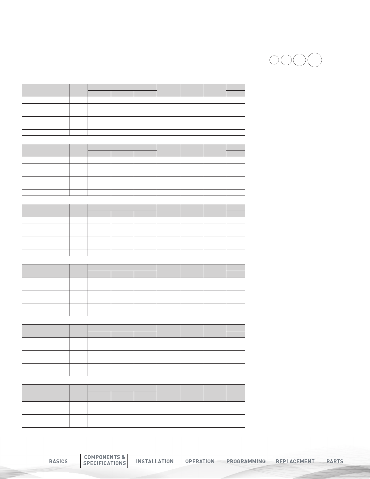
WATER AND TIME CONSUMED
DURING REGENERATION
Models Backwash
Minutes
75 10 10 20 70 80 100
100 10 10 20 80 100 140
150 10 10 20 100 140 200
200 10 10 20 140 200 280
300 10 10 20 200 280 340
Rapid Rinse
Minutes
Total
Time of
Regeneration
Total Water
Consumed during
Regeneration (GAL)
(Birm, TO, Neu)
Total Water Consumed
during Regeneration
(GAL) (MM)
Total Water Consumed
B
SYSTEM DIMENSIONS
Models A (Inches) B (Inches) C (Inches)
75
100
150
200
300
51.5 13" 8"
55.5 15" 9"
61.5 16" 10"
59.5 17" 12"
72.5 18" 14"
A
during Regeneration
(GAL) (Nexsand)
CONTROL VALVE
REGENERATION
SEQUENCE
The regeneration cycle goes through 3 steps.
1. BACKWASH (MINIMUM 30 PSI INLET
PRESSURE REQUIRED): During the backwash cycle, water
flows upwards through the bed, expanding the media and
carrying any contaminants trapped within it to the drain.
2. RAPID RINSE: During the rapid rinse cycle, water flows
downwards through the bed, settling the media and carrying
any precipitated contaminants trapped within it to the drain.
3. INSERVICE POSITION: The unit then returns to the In-Service
position. While this happens water continues to enter the tank.
C
Step1 Step 2
Step 3
7
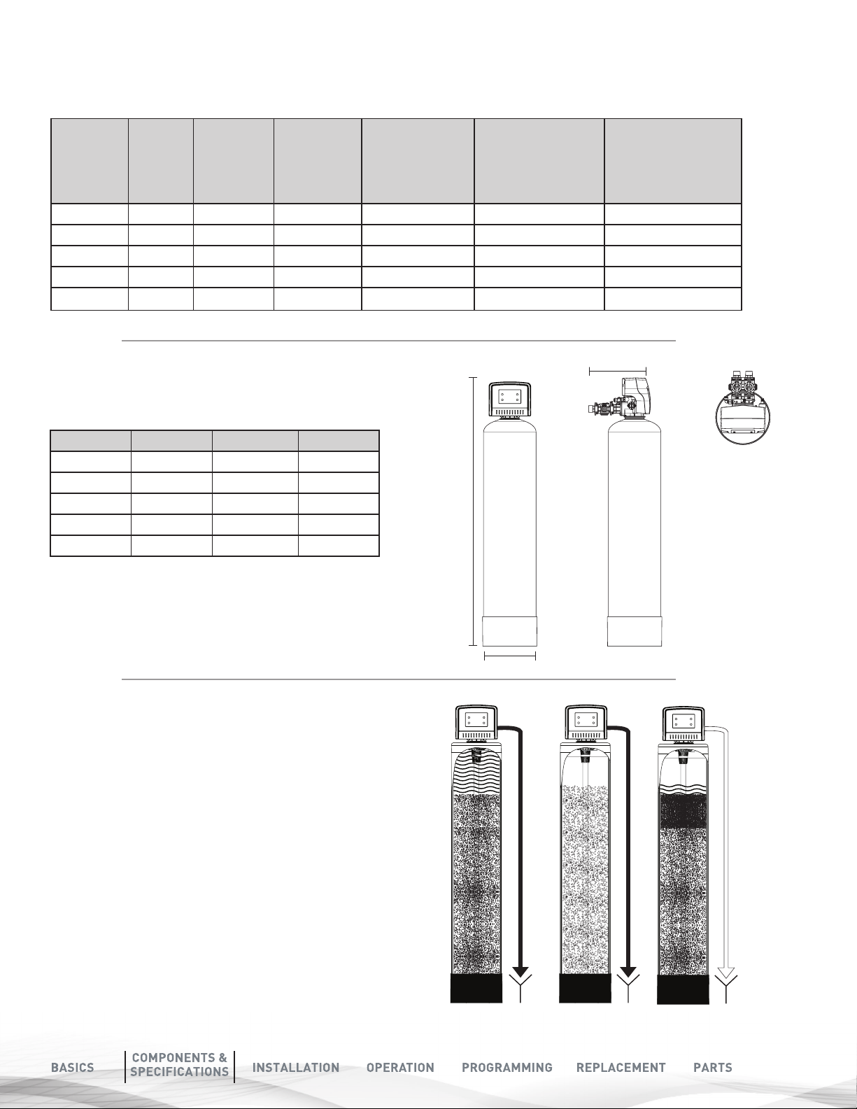
INSTALLATION
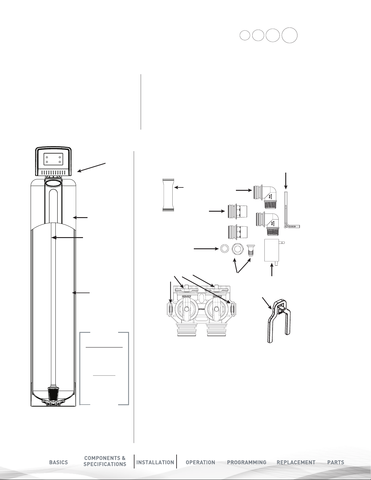
UNPACK & INSPECT PLATINUM FILTER
PLATINUM FILTER CONTENTS:
FOR MODELS 75,100,150, TO200, BIRM200,
YOU WILL EXPECT THE FOLLOWING.
SHIPPING CARTON QUANTITY 1
1. Control Valve
2. Pressure Tank
3. Parts Box
4. Owners Manual
5. Drain Hose & Clamp
(Not included in some brands)
1. CONTROL
VALVE
2. TANK
Distributor
Tube Inside
the Tank
• Check the entire unit for any shipping damage or lost parts.
• Note any damage to the shipping cartons.
• Contact the transportation company for all damage and loss claims.
• The manufacturer is not responsible for damages in transit.
• Small parts needed to install the softener are in a parts box.
• To avoid loss of the small parts keep them in the parts bag until you are ready to install.
• Handle the softener unit with care.
• Do not drop the unit or set on sharp uneven projections on the floor.
• Do not turn the softener unit upside down.
3. PARTS BOX
Grease
Packet
2X 1”
Straight
Adapter
Drain Line
Gasket
2 X 1”
Elbow
Adapter
(Not
Included)
Bypass Tool
Media Inside
the Tank.
Media Type will
depend on what
models were
purchased
NOTE
Only 8”, 9” & 10”
Pressure tanks
have plastic
sleeves.
8”, 9” & 10” tanks
come filled with
media & control
value attached
Bypass with 4
Red Clips
Drain Hose Barb
2 x Clips
Transformer
8
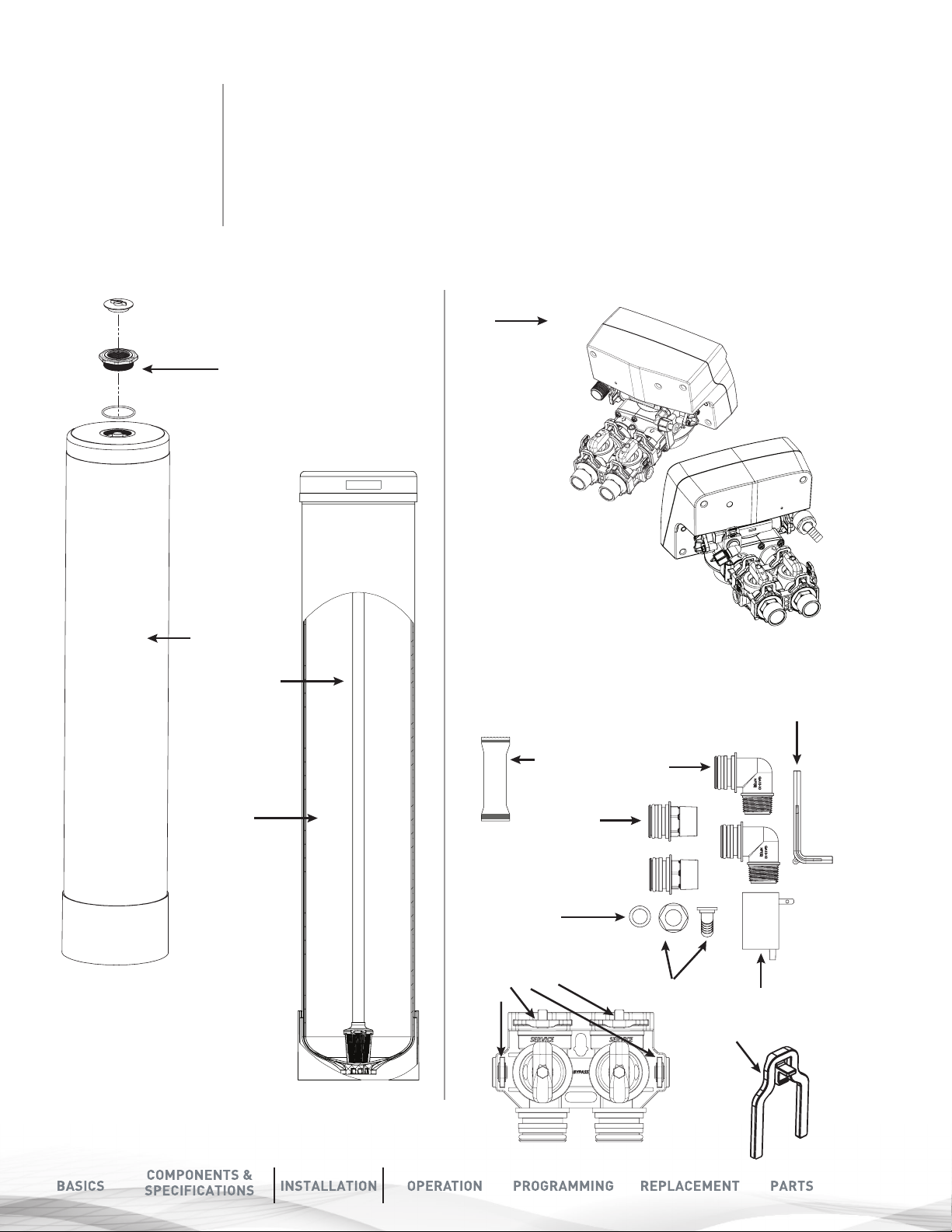
FOR MODELS 200, 300
THE MEDIA AND
CONTROL VALVE
IS PACKAGED
SEPARATELY IN
CARTON AND BAGS
Model 300 will get
Adaptor and O-ring
PLATINUM FILTER CONTENTS :
200, 300
1. Tank
(Model 30 will get an Adaptor and O-ring attached to the tank)
2. Control Valve with Parts Box
3. Media Boxes (Qty 2 for 200, Qty 3 for 300
4. Drain Line and Hose Clamp (Not Included) with some models
2. CONTROL
VALVE
Shown
1. TANK
Distributor
Tube Inside
the Tank
Media Inside
the Tank.
Media Type will
depend on what
models were
purchased
3. PARTS BOX
Grease
Packet
2X 1”
Straight
Adapter
Drain Line
Gasket
Bypass with 4
Red Clips
2 X 3/4”
Elbow
Adapter
(Not
Included)
Drain Hose Barb
2 x Clips
Bypass Tool
Transformer
9
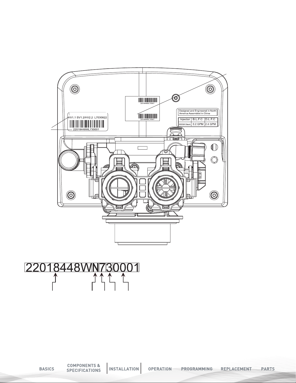
CHECK THE VALVE SERIAL NUMBER
AND VALVE TYPE
Check to make sure the valve type matches what you ordered.
The serial # label on the left will show BPCVPLATUF for Upflow valve
The right Sticker shows the serial # of the control valve.
The middle Sticker is dataplate which provides information of Serial # and Date of Manufacture of complete system.
Both Serial # labels are important for troubleshooting.
COMPLETE SYSTEM
SERIAL NUMBER
Item #
Desc
Date of Manufacture
BPCVPLATUF
VALVE SERIAL
NUMBER
Serial #
VALVE SERIAL NUMBER:
10
(22018448W): Part #
(L)YEAR : ’’ N’’ stand for 2017 year,’’ M’’ stand for 2016
year,’’ L’’ stand for 2015, ’’K’’ stand for 2014, ’’J’’ stand for
2013
Year Month Date Batch #Part #
(7)MONTH: 1 (JAN) 2(FEB) 3(MAR) 4(APRIL) 5(MAY)
6(JUNE) 7(JULY) 8(AUG) 9(SEP) A(OCT) B(NOV) C(DEC)
(3)DATE: 1 2 3 4 5 6 7 8 9 A(10) B(11) C(12) D(13) E(14)
F(15) G(16) H(17) I(18) J(19) K(20) L(21) M(22) N(23) O(24)
P(25) Q(26) R(27) S(28) T(29) U(30) V(31)
(0001): Batch code
PRE-INSTALLATION INSTRUCTIONS
CHECK YOUR WATER HARDNESS
Use test strips (Part # 2793828-20) to get an estimation of water hardness. Contact your local BRITA®PRO dealer to use a
BRITA®PRO laboratory for a complete water analysis free of cost and no obligation to you.
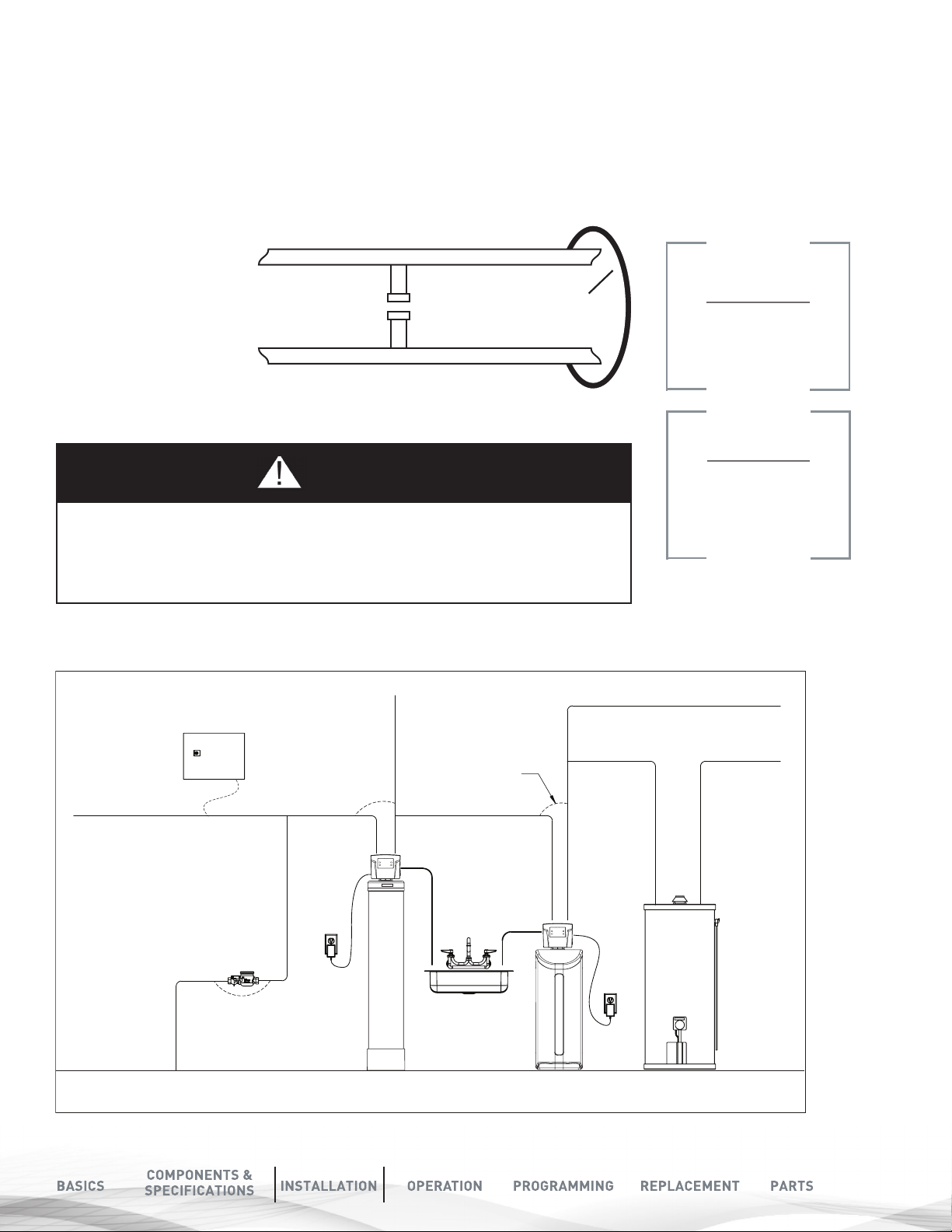
ELECTRICAL GROUNDING
An approved grounding
strap must be used in all
cases where metal pipe was
originally used and is later
interrupted by poly pipe,
the Noryl bypass valve or
by physical separation. The
grounding clamp used for
continuity, must be no less
than #6 copper conductor
to maintain proper metallic
pipe bonding.
8QILOWHUHG:DWHU%\SDVV
/RRS&XW&DSSHG
)LOWHUHG:DWHU/LQHLQ+RPH
*URXQG6WUDS5HTXLUHG%HFDXVH
RI%UHDNLQ&RQWLQXLW\
NOTE
Check your local
electrical code for
the correct strap.
NOTE
CAUTION
The ground from the electrical panel or breaker box to the water meter or underground
copper pipe is tied to the copper water lines. If these lines are cut during installation
of the Noryl bypass valve and/or poly pipe, an approved grounding strap must be used
between the two lines that have been cut. This will maintain continuity. The length of the
grounding strap will depend upon the number of units being installed and/or the amount
FIGURE 1A: TASTE AND ODOR FILTER (TO)
TYPICAL INSTALLATION:
Raw Water
To Outdoors
of copper pipe being replaced with plastic pipe. See drawing below.
Hard
Electrical Panel
Filtered
Water
Ground Strap
Drain
Drain
You must follow all
government codes and
regulations governing
the installation of
these devices.
Cold Soft Water
Hard Soft Water
Water Meter
Taste and Odor
(TO) Filter
Softener
Water Heater
11

FIGURE 1B: BIRM (BM) TYPICAL INSTALLATION:
Raw Water
To Outdoors
Electrical Panel
Water Meter
Birm
(BM) Filter
Hard
Filtered
Water
Drain
Ground Strap
Drain
Softener
Cold Soft Water
Hard Soft Water
Water Heater
FIGURE 1C: MULTI MEDIA FILTER (MM OR NEXSAND) TYPICAL INSTALLATION:
Raw Water
To Outdoors
Electrical Panel
Water Meter
Hard
Filtered
Water
Ground Strap
Drain
Drain
Cold Soft Water
Hard Soft Water
12
Multi Media
Filter (MM or nextSand)
Taste and Odor
(TO) Filter
Softener
Water Heater
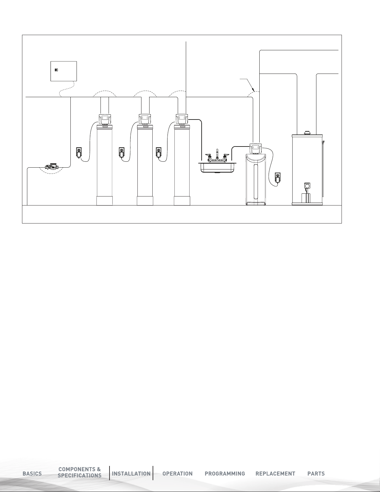
FIGURE 1D: NEUTRALIZING FILTER (NF) TYPICAL INSTALLATION:
Raw Water
To Outdoors
Water Meter
Electrical Panel
Multi Media
Filter (MM or neXtSand)
Multi Media
Filter (NU)
Hard
Filtered
Water
Drain
Taste and Odor
(TO) Filter
Ground Strap
Drain
Softener
Cold Soft Water
Hard Soft Water
Water Heater
13

TOOLS REQUIRED FOR
CHECK WATER
INSTALLATION:
Two adjustable wrenches
Additional tools may be required if modifications to home
plumbing are required.
Plastic inlet and outlet fittings are included with the softener. 3/4”
or 1” pipes to and from the softener fittings are recommended to
maintain full valve flow. You should maintain the same or larger
water supply pipe sizes as the softener inlet and outlet pipe sizes.
Use copper, brass, or PEX pipe and fittings.
Some codes may also allow PVC plastic pipe. Refer to local codes.
ALWAYS INSTALL THE INCLUDED BYPASS VALVE, OR 3 SHUT-OFF
VALVES. Bypass valves let you turn off water to the softener for
repairs, but still have water in the house pipes.
5/8” OD drain line is needed for the valve drain. A 10’ length of
hose is not included with some brands
NOTE
If the plumbing system is used as the ground leg of
the electric supply, continuity should be maintained
by installing ground straps around any nonconductive
plastic piping used in installation.
PRESSURE AND
PUMPING RATE
Two water system conditions must be checked carefully
to avoid unsatisfactory operation or equipment damage:
1. Minimum water pressure required at the softener
tank inlet is 30 psi.
2. The pumping rate of your home’s well pump must at
least equal to the required backwash flow rate of your
model (see Specifications on Page 6 for backwash
flow rates).
TO MEASURE THE PUMPING RATE OF YOUR
PUMP, FOLLOW THESE INSTRUCTIONS:
A. Determine the cycle time. Make certain no water is
being drawn. Open spigot nearest pressure tank.
When pump starts, close spigot and measure time (in
seconds) to refill pressure tank (when pump shuts
off). This figure represents cycle time.
B. Determine drawn-down time. With the pressure tank
full, draw water into a container of known volume and
measure the number of gallons drawn until the pump
starts again. This is draw-down.
C. Determine drawn cycle time. Divide the draw down
time by cycle time and multiply the result by
60 to arrive at the pumping rate in gallons per
minute (gpm).
DETERMINE THE CORRECT
LOCATION OF THE WATER
CONDITIONING EQUIPMENT
Determine the best location for your water softener, bearing in mind the
location of your water supply lines, drain line and 120 volt AC electrical
outlet. Subjecting the softener to freezing or temperatures above 43°C
(110°F) will void the warranty. Review the various conditions below to
determine a proper location:
1. Locate as close as possible to the water supply source.
2. Locate as close as possible to a floor or laundry tub drain.
3. Locate in correct relationship to other water conditioning
equipment (see Fig. 1 on Page 10)
4. Softener should be located in the supply line before the water heater.
Temperatures above 120°F damage softeners.
5. Do not install a softener in a location where freezing temperatures
occur. Freezing may cause permanent damage to this type of
equipment and will void the factory warranty.
6. Allow sufficient space around the unit for easy servicing.
7. Determine if additional plumbing is required if your water source is a
community water supply, a public water supply or you wish to bypass
water used for a geothermal heat pump, lawn sprinkling,
out-buildings or other high demand applications, refer to Fig. 1.
8. Keep the softener out of direct sunlight. Heat build up from direct
sunlight may soften and distort plastic parts.
To aid in your calculation, insert the data in the
following formula:
DRAW-DOWN________ (gals)
÷ CYCLE TIME______________x 60 (seconds)
= PUMPING RATE______________ (gpm)
EXAMPLE:
DRAWDOWN is 6 gals; CYCLE TIME is 53 secs; then,
PUMPING RATE equals: 6 gals ÷ 53 secs x 60 = 6.8 gpm
SEE SPECIFICATIONS ON PAGE 6
FOR MINIMUM FLOW RATES.
.
NOTE
If there is a severe loss in water pressure when the
softener unit is initially placed in service, the softener
tank may have been laid on its side during transit. If this
occurs, backwash the softener to “reclassify” the media.
14
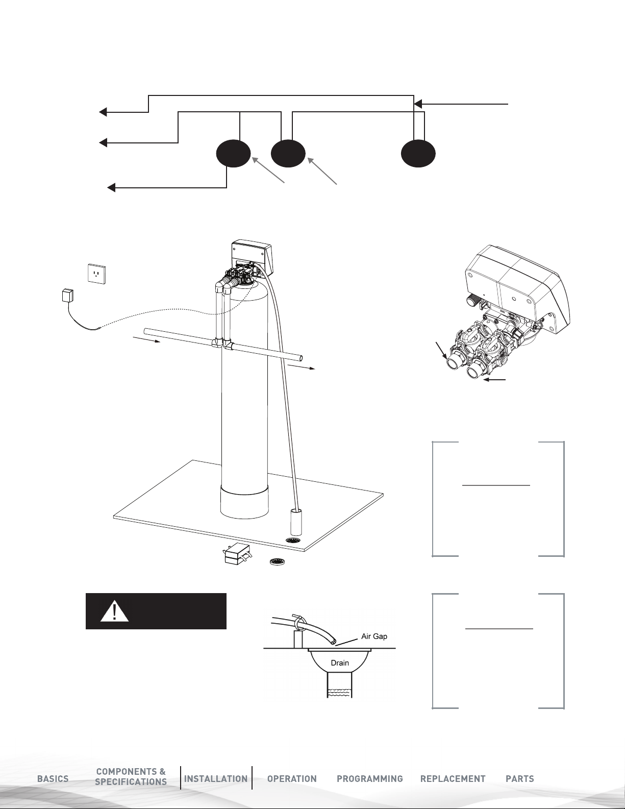
2XWOHW
,QOHW
tI
T
FILTER INSTALLATION
Cold (Raw water)
o Outside Faucet
Cold (Soft Water)
Cold (Filtered water)
InIn Ou
Cold (Raw water)
nOut
Filter
Hot (Soft Water)
Out
Water Heater
Water Softener
Inlet
Outlet
Opposite Most
Standard Softeners
NOTE
The valves are labeled
inlet and outlet on the
vale. Please make sure
to plumb as shown here
CAUTION
Never insert the drain line directly
into a drain, sewer line, or trap.
Always allow an air gap between
the drain line and the wastewater.
This will prevent the possibility of
sewage being back-siphoned
into the conditioner.
NOTE
The waste connection or drain
outlet shall be designed and
constructed to provide an
air-gap to the sanitary waste
system of 2 pipe diameters or
1 inch (22 mm).
(whichever is larger)
15
 Loading...