


BriskHeat X2J-BIH101020L, X2J-BIH101100L, X2J-BWH051080L, X2J-BWH051080LD, X2J-BWH051060L Instruction Manual
...English
X2 Benchtop PID Digital
Temperature Controller
Instruction Manual
Read and understand this manual before operating or servicing this temperature controller. Failure to understand how to safely operate this controller could result in an accident causing serious injury or death. Only qualified personnel should operate or service this controller.
Language |
Page |
English ..................................................................................................... |
1 |
Spanish (Español).................................................................................... |
17 |
French (Français)..................................................................................... |
33 |
German (Deutsch).................................................................................... |
49 |
Italian (Italiano)......................................................................................... |
65 |
X2 Benchtop |
|
PID Digital Temperature Controller |
|
TABLE OF CONTENTS |
|
Introduction................................................................................................................................... |
2 |
Important Safety Instructions........................................................................................................ |
3 |
About the X2................................................................................................................................. |
4 |
General Specifications ......................................................................................................... |
4 |
Technical Specifications....................................................................................................... |
5 |
Part Number Matrix and Accessories................................................................................... |
5 |
Dimensions .......................................................................................................................... |
6 |
Installation .................................................................................................................................... |
7 |
Appropriate Installation Location .......................................................................................... |
7 |
Mounted Control Option ....................................................................................................... |
8 |
Connecting Controller to Heater and Power Source ............................................................ |
9 |
Programming Your Controller ....................................................................................................... |
10 |
Basic Functions.................................................................................................................... |
10 |
Complete Functions List (Levels 1 to 3) ............................................................................... |
10 |
PID Auto-Tune ..................................................................................................................... |
12 |
Troubleshooting and Error Messages........................................................................................... |
14 |
Fuse Replacement ....................................................................................................................... |
15 |
Warranty Information .................................................................................................................... |
15 |
INTRODUCTION |
SAFETY ALERT SYMBOL |
Thank you for purchasing a BriskHeat® X2 Benchtop PID Digital Temperature Controller. Your controller is designed for general purpose use in indoor environments to control temperatures on applications requiring automatic control. The controller provides a simple three-key user control and a plug-and-play set-up. For successful operation of this controller, read and understand these instructions prior to use.
SAVE THESE INSTRUCTIONS!
Additional copies of this manual are available upon request.
The symbol above is used to call your attention to instructions concerning your personal safety. It points out important safety precautions. It means “ATTENTION! Become Alert! Your Personal Safety is involved!” Read the message that follows and be alert to the possibility of personal injury or death.
Immediate hazards which WILL result in severe personal injury or death.
Hazards or unsafe practices that COULD result in severe personal injury or death.
Hazards or unsafe practices that COULD result in minor personal injury or property damage.
© BriskHeat® Corporation. All rights reserved. 2
X2 Benchtop
PID Digital Temperature Controller
IMPORTANT SAFETY INSTRUCTIONS

 DANGER
A person who has not read and understood all operating Instructions is not qualified to operate this product.

 DANGER
Do not immerse or spray any component of the control system with liquid.
Keep volatile or combustible material away from controller when in use.
Keep sharp metal objects away from heater.
Use controller only ordinary (non-hazardous) locations
Agency Approvals
Approvals valid only when installed in accordance with all applicable instructions, codes, and regulations.

 CAUTION
Inspect all components before use.
Do not repair damaged or faulty controller
Do not crush or apply severe physical stress on any component of system, including cord assembly.
Failure to observe these warnings may result in electric shock, risk of fire, and personal injury.

 WARNING
End-User Must Comply to the Following:
Only qualified personnel are allowed to connect electrical wiring.
All electrical wiring must follow local electrical codes and NEC Article 427.
Unplug control and heating system when not in use.
Failure to observe these warnings may result in personal injury or damage to the heater.

 DANGER
Do not use Set Point 2 as the sole alarm where personal injury or damage may be caused by equipment failure.
The person who performs the final installation / wiring must be qualified for this work.
The end-user is responsible for providing a suitable disconnect device.
The end-user is responsible for providing a suitable over-current protection device. It is highly recommended that a ground-fault circuit breaker be used.
Failure to observe these warnings may result in personal injury or damage to the heater.
© BriskHeat® Corporation. All rights reserved. 3
X2 Benchtop
PID Digital Temperature Controller

 WARNING
Read and understand this entire manual before operating this controller.
ABOUT THE X2
General Specifications
For indoor general purpose applicationsPortable, plug-and-play design
PID Control, automatic tuning of PID parametersSimple three-key user control
Operating temperature range:
32 to 1400°F (0 to 760°C) for J/K Thermocouple
-273 to 750°F (-200 to 400°C) for Pt100 / RTD-2
Programmable in either °C or °F (Default set point is 0°C).Type J or K thermocouple mini connector input
Thermocouple sold separately or RTD (Pt100)
Operating Voltage:
100-130VAC, 50 to 60hz, +/-10% maximum permitted fluctuation
200-240VAC, 50 to 60hz, +/-10% maximum permitted fluctuation
User Programmable alarm types including latching optionsProgrammable security lock levels
Fused input
Environmental temperature range:
32-130°F (0-50°C)
80% maximum humidity
Altitude:
Up to 2000M
Sensor break protection with average output option which allows process to continue heating
Auto / manual control ability
Includes a mating AMP Mate-N-Lock power connector to be added to heater
Output power cords with different plug receptacles sold separately. Contact BriskHeat® at 1-800-848-7673 or 1-614-294-3376 for more information.
Note: Check Part Number on Control to confirm sensor type and voltage match your requirements and supply. Refer to the “Part Number Matrix and Accessories” selection for details.
© BriskHeat® Corporation. All rights reserved. 4

X2 Benchtop |
|
X2 Benchtop |
PID Digital Temperature Controller |
|
PID Digital Temperature Controller |
Technical Specifications |
Dimensions |
Thermocouple |
2 types |
Standards: |
IPTS/68/DIN 43710 |
CJC rejection: |
20:1 (0.05°/°C) typical |
External resistance: |
100Ω maximum |
Calibration accuracy: |
±0.25%SM ±1°C (SM = sensor maximum) |
Sensor Range: |
J Type: 0°C (32°F) to 800°C (1472°F), Linearity 0.5 |
|
K Type: -50°C (-58°F) to 1200°C (2192°F), Linearity 0.25 |
|
RTD Type: -200°C (-273°F) to 400°C (752°F), Linearity 0.25 |
Sampling frequency: |
Input 10Hz, CJC 2 sec. |
Common mode rejection: |
Negligible effect up to 140dB, 240V, 50-60Hz |
Series mode rejection: |
60dB, 50-60Hz |
Temperature coefficient: |
150ppm/°C SM |
Reference conditions: |
22°C ±2°C, rated voltage after 15 minutes settling time. |
Display: |
4 Digits, high brightness Green LED, 10mm (0.4”) high. |
Digital range: |
-199 to 9999 |
Hi-res mode: |
-199.9 to 999.9 |
Keypad: |
3 elastomeric buttons |
LED output indicators: |
SP1 round, green or red; SP2 round, green or red |
Part Number Matrix and Accessories
PART NUMBER MATRIX:
X2 - XXX Y Z E
BLANK (NORTH AMERICA)
E (EUROPE)
CONFIGURATION / OPTIONS
TABLE TOP (T)
INCLUDES STAND CLAMP (S)
THERMOCOUPLE / SENSOR INPUT
J TYPE |
(J) |
K TYPE |
(K) |
PT100/RTD-2 (R)
TENSIÓN DE ENTRADA
120 V CA (120
240 V CA (240)
Accessories:
TAJN05-AA |
Type J Thermocouple; mini connector; 5ft (1.5m) |
|
TAJN10-AA |
Type J Thermocouple; mini connector; 10ft (3.0m) |
|
TAKN05-DA Type K Thermocouple; mini connector; 5ft |
(1.5m) |
|
TAKN10-DA Type K Thermocouple; mini connector; 10ft |
(3.0m) |
|
X2RTD-013 Pt100/RTD-2; 13ft (4.0m)
© BriskHeat® Corporation. All rights reserved. 5
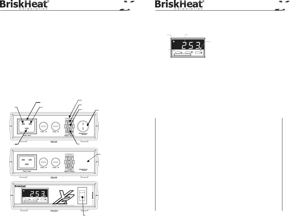
REAR
© BriskHeat® Corporation. All rights reserved. 6

X2 Benchtop |
|
X2 Benchtop |
PID Digital Temperature Controller |
|
PID Digital Temperature Controller |
INSTALLATION |
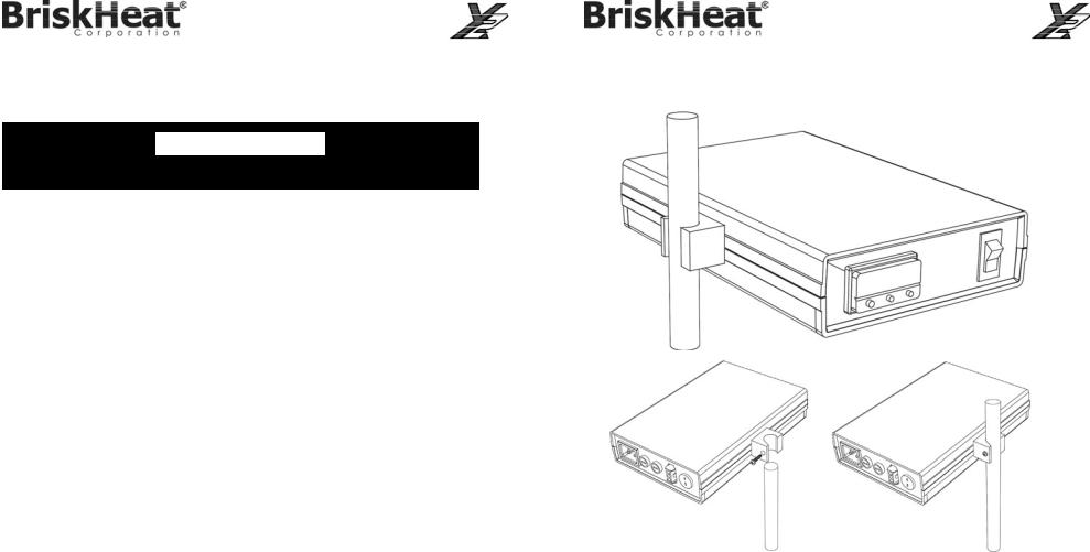
Mounted Control Option |
|
Appropriate Installation Location |
|
|
Read and understand this entire manual before operating this controller.
CHOOSE AN APPROPRIATE LOCATION WITH THE FOLLOWING PARAMETERS:
Proximity to a suitable power supply:
Power input cord is 6 foot, (1.8 meter).
Appropriate clearances:
To allow easy installation of connectors.
Ambient temperature:
Within the range of 32-130°F (0-50°C).
Humidity conditions:
Within the range 0 to 80%.
The controller’s resting surface must be stable and easy to access for operation.
Note: If the temperature controller is to be mounted, make sure the mounting location is easily accessible.
How to mount the temperature controller:
1. Place the mounting pole inside the mounted bracket. The bracket will accept up to a mounting pole up to 0.75” (19mm). (Mounting pole is not supplied.)
2. Close the bracket and tighten the closure screw securely.
© BriskHeat® Corporation. All rights reserved. |
© BriskHeat® Corporation. All rights reserved. |
7 |
8 |
X2 Benchtop
PID Digital Temperature Controller
Connecting Controller to Heater and Power Source
1.When installing the controller, ensure that the controller’s thermocouple sensor makes good contact with both the heater and the object being heated.
a.Consult the heater’s installation manual for proper installation of the heater that is being connected to the controller.
2.Plug heater or optional BriskHeat® output cord into ‘Heater Output’ receptacle in the back of the temperature controller.
a.Make sure the plug on the heater or optional output power cord has an AMP Mate- N-Lock 3- prong plug and is compatible with the AMP Mate-N-Lock receptacle on the temperature controller.
3.Connect the receptacle end of the included input power cord into “Power Input” plug in the back of the temperature controller. Plug the power input cord into a properly rated power supply.
4.Flip power switch located in the front to the ‘On’ position.
Refer to the “Programming Your Controller” section for programming instructions.
|
Input Power |
Heater Output |
||
|
L1 |
|
||
L1 |
L2 |
|
||
GND |
Thermocouple |
|||
|
|
|||
GND |
L2 |
RTD
Power Switch
© BriskHeat® Corporation. All rights reserved. 9
X2 Benchtop
PID Digital Temperature Controller
PROGRAMMING YOUR CONTROLLER
Basic Functions
Main |
Process Temperature (PV |
Routine Adjustments |
||
or Setpoint (SP) |
* |
|
View Setpoint |
|
Setpoint |
|
|||
|
▲ |
Increase Setpoint |
||
SP1 |
Second |
|||
|
Setpoint |
** |
▼ |
Decrease Setpoint |
Setpoint |
SP2 |
Reset Alarm or Fault Message |
||
Indicator |
|
▲▼ |
Momentarily Press Together |
|
|
|
|
|
|
Markers
To enter or exit program mode: Press (▲▼) together for 3 secondsTo scroll through functions: Press (▲) or (▼)
To change levels or options: Press ( *▲) together or ( *▼)togetherTo view setpoint: Press (*)
To increase setpoint: Press ( *▲) togetherTo decrease setpoint: Press ( *▼) together
To reset an alarm or fault condition: Press (▲ ▼) together briefly
When in program mode, after 60 seconds of key inactivity the display will revert to either inPt:nonE or, if the initial configuration has been completed, the measured value. Any settings already completed will be retained.
Complete Function List (Levels 1 to 3)
LEVEL 1
Function |
Options [Factory |
Description |
|
settings] shown |
|
|
|
|
Select Autotune
tunE |
[oFF], on, ParK, |
Used to switch the Autotune feature on and off, to select ParK or tune at setpoint. |
|
At.Sp |
ParK temporarily turns the output(s) off. To use select ParK and exit program mode. To |
|
|
|
SP1 Operating Parameters
bAnD |
0.1 to * C/°F |
SP1 proportional band/Gain or Hysteresis |
|
[10ºC/18ºF] |
* 25% sensor maximum Proportional control eliminates the cycling of on-off control. |
|
|
|
int.t |
oFF, 0.1 to 60 |
SP1 integral time/reset Auto-corrects proportional control offset error |
|
minutes [5.0] |
|
dEr.t |
oFF 1 - 200 |
SP1 derivate time/rate Suppresses overshoot and speeds response to disturbances |
|
seconds [25] |
|
dAC |
0.5 - 5.0 x bAnd |
SP1 derivative approach control dAC Tunes warm-up characteristics, independent |
|
[1.5] |
of normal operating conditions, by controlling when derivative action starts during |
|
|
|
CyC.t |
A – –, on.oF, |
SP1 proportional cycle-time (see section above) |
|
0.1 - 81 sec |
Determines the cycle rate of the output device for proportional control. Select on.oF for |
|
[20] |
ON/OFF mode. |
oFSt |
[0] to * °C/°F |
SP1 offset/manual reset |
|
|
* ±50% bAnd. Applicable in proportional and ON/OFF mode with integral disable: |
|
|
|
SP.LK |
[oFF] on |
Lock main setpoint Locks the setpoint preventing unauthorized adjustment. |
|
|
|
© BriskHeat® Corporation. All rights reserved. 10

|
|
|
|
|
|
X2 Benchtop |
|
|
|
|
|
|
|
PID Digital Temperature Controller |
|
|
|
|
|
||||
Function |
|
Options [Factory settings] |
Description |
||||
|
|
shown in brackets |
|||||
|
|
|
|
||||
SP2 Operating Parameters |
|
||||||
SEt.2 |
0 to |
* |
°C/°F [0] |
|
|
Adjust SP2 setpoint |
|
|
|
|
|
|
|
* Deviation Alarms DV.hi, DV.Lo, bAnd 25% sensor maximum. |
|
|
|
|
|
|
|
* Full scale alarms FS.hi, FS.Lo sensor range f/s |
|
bnd.2 |
0.1 - |
* |
°C/°F [2.0 °C/3.6°F] |
Adjust SP2 hysteresis or proportional band/gain (see CyC.2 |
|||
|
|
|
|
|
|
setting) |
|
|
|
|
|
|
|
* 25% sensor full scale |
|
CyC.2 |
[on.oFF] 0.1–81 seconds |
Select SP2 ON/OFF or proportional cycle-time |
|||||
|
|
|
|
|
|
Select on.oFF for ON/OFF mode, or the cycle rate of SP2 output |
|
|
|
|
|
|
|
device for proportional mode. |
|
LEVEL 2 |
|
|
|
|
|
|
|
|
|
|
|||||
Function |
Options [Factory settings] shown in |
Description |
|||||
|
|
brackets |
|||||
|
|
|
|
||||
Manual |
Control Modes |
|
|||||
SPI.P |
0 to 100 % ‘read only’ |
Read SP1 output percentage power |
|||||
hAnd |
[oFF] 1 to 100 % (not in ON/OFF) |
SP1 manual percentage power control For manual control should |
|||||
a sensor fail. Record typical SP1.P values beforehand. |
|||||||
|
|
|
|
|
|
||
PL.1 |
100 to 0 % duty cycle [100] |
Set SP1 power limit percentage Limits maximum SP1 heating |
|||||
power during warm-up and in proportional band. |
|||||||
|
|
|
|
|
|
||
PL.2 |
100 to 0 % duty cycle [100] |
Set SP2 percentage power limit (cooling) |
|||||
|
|
|
|
||||
SP2 Operating Modes |
|
|
|||||
SP2.A |
[none] dV.hi dV.Lo bAnd FS.hi |
Main SP2 operating mode |
|||||
|
FS.Lo Cool |
|
|
|
|||
|
|
|
|||||
SP2.b |
[none] LtCh hoLd nLin |
Subsidiary SP2 mode: latch/sequence ,Non-linear cool |
|||||
|
|
|
|
|
|
proportional band |
|
Input Selection and Ranging |
|
||||||
dI.SP |
[1] 0.1 |
|
|
|
Select display resolution: for display of process temperature, |
||
|
|
|
|
|
|
setpoint, OFSt, Set.2, hi.SC, LoSC |
|
hi.SC |
sensor minimum [sensor |
Set full scale |
|||||
|
maximum] °C/°F |
|
|
|
|||
Lo.SC |
[sensor minimum] sensor |
Set scale minimum (default 0°C or 32°F) |
|||||
|
maximum °C/ºF |
|
|
|
|||
|
|
|
|
|
|||
inPt |
[nonE] |
|
|
Select input sensor (See SENSOR SELECTION table) |
|||
|
|
|
|||||
Unit |
[nonE] °C °F bAr Psi Ph rh |
Select °C/°F or process units |
|||||
|
|
|
|
|
|
|
|
LEVEL 3 |
|
|
|
|
|
|
|
Function |
Options [Factory settings] shown in |
Description |
|||||
|
|
brackets |
|||||
|
|
|
|
||||
Output |
Configuration |
|
|
||||
SP1.d |
[nonE] rLY SSd |
|
|
Select SP1 output device |
|||
|
|
|
|
|
|
Note: ‘Read only’ after initial configuration. rSET ALL full reset to |
|
|
|
|
|
|
|
factory settings required to change SP1.d subsequently. |
|
SP2.d |
[nonE] SSd rLY |
|
|
Read SP2 output device (read only) |
|||
|
|
|
|
|
|
|
|
burn |
|
|
SP1 |
/ |
SP2 |
Sensor burn-out/break protection |
|
|
[uP.SC] Upscale |
/ Upscale |
|
||||
|
dn.SC |
Downscale/ Downscale |
CAUTION: Settings affect fail safe state. |
||||
|
1u.2d |
Upscale |
/ Downscale |
|
|||
|
1d.2u |
Downscale / Upscale |
|
||||
rEu.d |
|
|
SP1 |
/ |
SP2 |
Select output modes: Direct/Reverse |
|
|
[1r.2d] |
Reverse |
/ Direct |
Select Reverse on SP1 for heating and Direct for cooling |
|||
|
1d.2d |
Direct |
/ Direct |
applications. |
|||
|
1r.2r |
Reverse |
/ Reverse |
|
|||
|
1d.2r |
Direct |
/ Reverse |
CAUTION: Settings affect fail safe state. |
|||
|
|
|
|
|
|
|
|
© BriskHeat® Corporation. All rights reserved. 11
|
|
|
|
X2 Benchtop |
|
|
|
|
|
PID Digital Temperature Controller |
|
|
|
|
|||
Function |
Options [Factory settings] |
Description |
|||
shown in brackets |
|||||
|
|
||||
rEu.L |
|
SP1 / |
SP2 |
Select SP1/2 LED indicator modes |
|
|
[1n.2n] |
Normal |
Normal |
|
|
|
1i.2n |
Invert |
Normal |
|
|
|
1n.2i |
Normal |
Invert |
|
|
|
1i.2i |
Invert |
Invert |
|
|
|
|
|
|||
SPAn |
[0.0] to ±25% sensor |
Sensor span adjust |
|||
|
maximum |
|
For recalibrating to align readings with another instrument e.g. |
||
|
|
|
|
External Meter, data logger. See Full Operating Manual |
|
|
|
|
|
(ADVANCED SETTINGS). |
|
|
|
|
|||
ZEro |
[0.0] to ±25% sensor f/s |
Zero sensor error (see Sensor span adjust above). |
|||
ChEK |
[oFF] on |
|
|
Select control accuracy monitor |
|
|
|
|
|
||
rEAD |
[Var] hi Lo |
|
Read control accuracy monitor |
||
tECh |
[Ct A] CT b Ct 1 Ct 2 Ct 3 Ct 4 |
Read Autotune tuning cycle data (see Operating Manual) |
|||
|
oS 1 uS oS 2 |
|
|
||
UEr |
|
|
|
Software version number |
|
rSET |
[nonE] ALL |
|
Resets all functions to factory settings |
||
|
|
|
|
CAUTION: This selection will lose all of the current settings. |
|
|
|
|
|
|
|
PID Auto-Tune
This is a single shot procedure to match a controller to the process. Select either Tune or Tune at Setpoint from the criteria below.
Use Tune function when the load temperature is at or near ambient. This function applies disturbances when the temperature reaches 75% of the set point value, causing an overshoot and then adjusts the DAC overshoot inhibit value. Ensure an overshoot is safe for the process.
The Tune at Setpoint function is recommended when:
The process is at set point and control is poor
The set point is less than 100°C
Re-tuning after a large set point change
Tuning multi-zone and/or heat-cool applications.
Note: DAC is not re-adjusted by Tune at setpoint.
Proportional Cycle Time can be pre-selected before running the Autotune program.
The symbol (▲▼) signifies both buttons are held pressed for 3 seconds to ENTER or EXIT program mode.
STEPS TO TUNE OR TUNE AT SETPOINT PROGRAM
Enter program (▲ ▼) and from the display tunE : oFF press and hold Þ and press ▲ to display tunE : on or tunE : At.SP
Exit program mode (▲ ▼).
The TUNE program will now start. The display will show tunE as the process temperature climbs to setpoint.
Note: During tuning, the main setpoint (SP1) LED will flash.
© BriskHeat® Corporation. All rights reserved. 12

X2 Benchtop
PID Digital Temperature Controller
When the TUNE or TUNE AT SETPOINT program is complete the PID values are updated automatically. The process temperature will rise to setpoint and control should be stable. If not, this may be because optimum cycle time is not automatically implemented. To set the cycle time see
PROPORTIONAL CYCLE-TIME.
PROPORTIONAL CYCLE-TIME
The choice of cycle-time is influenced by the external switching device or load. e.g. Contactor or SSR. A setting that is too long for a process will cause oscillation or a setting that is too short will cause unnecessary wear to an electro-mechanical switching device.
Factory set - To use the 20 sec factory set cycle-time no action is needed whether autotune is used or not.
To Manually Select AUTOTUNE Calculated CYCLE-TIME
When AUTOTUNE is completed, enter program (▲ ▼) and select CYC.t in Level 1. The display will read CYC.t:20 (factory setting)
To view the new calculated optimum value, press and hold both Þ and ▼ buttons until indexing stops. The calculated value will be displayed e.g. A16. If acceptable, exit program (▲ ▼) to implement this setting.
To Pre-select Automatic Acceptance of AUTOTUNE Calculated CYCLE-TIME
Before AUTOTUNE is initiated select CYC.t in Level 1, press and hold both Þ and ▼ buttons until indexing stops at A – –. Exit program (▲ ▼) to accept calculated value automatically.
To Manually Pre-select Preferred CYCLE-TIME
Before AUTOTUNE is initiated select CYC.t in Level 1, press and hold both Þ and ▲ or ▼ buttons until indexing stops at preferred value then exit program (▲ ▼) to accept.
CYCLE-TIME RECOMMENDATIONS
Output device |
Factory setting |
Recommended minimum |
Internal relay : |
20 seconds |
10 seconds |
|
|
|
Solid state drive : |
20 seconds |
0.1 seconds |
|
|
|
X2 Benchtop
PID Digital Temperature Controller
TROUBLESHOOTING GUIDE AND ERROR MESSAGES
Please read this guide prior to contacting BriskHeat®. This guide is designed to answer the most commonly asked questions. If you are unable to identify the problem or need additional assistance, please contact your local distributor/ representative or us at 1-800-848-7673,
614-294-3376, or bhtsales1@briskheat.com.
Troubleshooting
PROBLEM |
SOLUTION |
ACTION |
|
Controller does |
Plug is disconnected from outlet |
Make sure plug is securely connected |
|
not turn on |
|
|
|
Power switch is not on |
Turn switch to on position |
||
|
|||
|
|
|
|
|
Fuse has blown |
Replace fuse |
|
|
|
|
|
Temperature |
Setpoint is too low |
Increase the setpoint value |
|
does not |
|
|
|
Controller parameters are set |
Review operating procedures and reset |
||
increase |
|||
improperly |
parameters |
||
|
|||
|
|
|
|
|
Fuse has blown |
Replace fuse |
|
|
|
|
|
Heater does not |
Plug is disconnected from outlet |
Make sure plug is securely connected |
|
warm up |
|
|
|
Heater may be damaged |
Check resistance reading |
||
|
|||
|
|
|
|
|
|
Contact factory for target reading and |
|
|
|
assistance |
|
|
|
|
Error Messages
DISPLAY |
FAULT TYPE |
|
ACTION |
inPt: FAiL |
SENSOR FAULT |
Check sensor/wiring |
|
|
Thermocouple burnout or negative |
|
|
|
over-range. |
|
|
|
|
|
|
dAtA : FAiL |
NON-VOLATILE MEMORY ERROR |
De-power briefly |
|
|
|
Replace unit if problem persists |
|
|
|
|
|
hAnd : FAiL |
MANUAL POWER ERROR |
Select proportional mode |
|
|
SP1 set to ON/OFF in CYC.t |
|
|
tunE : FAiL |
IMMEDIATE FAIL ON AUTOTUNE |
1. |
If display setpoint=0 then enter setpoint |
|
START |
2. |
If SP1 set to ON/OFF in CyC.t then select |
|
|
||
|
Note: To reset and clear error press |
|
proportional mode |
|
(▲ ▼) together briefly to cancel |
3. |
Change conditions. e.g. raise setpoint |
|
message. |
||
|
|
|
|
|
FAIL LATER DURING AUTOTUNE |
4. |
Try tunE : At.SP |
|
|
|
|
|
CYCLE |
5. |
If the error message persists, contact |
|
|
||
|
The thermal characteristics of the load |
|
BriskHeat® directly for further assistance. |
|
|
|
|
|
exceed the autotune algorithm limits. |
|
|
|
The failure point is indicated by any |
|
|
|
display 0.0 in tech e.g. Ctb = 0.0 |
|
|
|
|
|
|
© BriskHeat® Corporation. All rights reserved. |
© BriskHeat® Corporation. All rights reserved. |
13 |
14 |
X2 Benchtop
PID Digital Temperature Controller
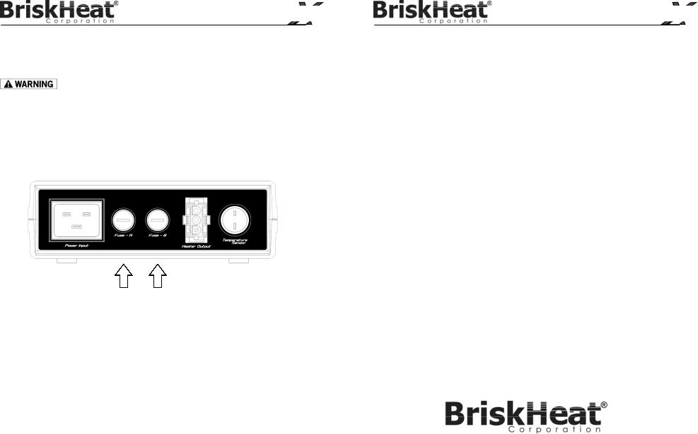
FUSE REPLACEMENT
Fuse should be replaced with properly rated fuse: 15 AMP @ 250VAC max. Fast-acting, example part number: Bussman ABC-15-R
Do not replace fuse with live power applied to controller. Only authorized personnel should replace fuse.
1.Remove power from unit.
2.Replace the blown fuse with a new one of the specified amperage.
3.Apply power to unit.
4.If replacement fuse immediately fails, contact BriskHeat® for more information concerning your issue.
Fuse holders can be removed using a flat-head screw-driver.
BACK VIEW
WARRANTY INFORMATION
BriskHeat warrants to the original purchaser of this product for the period of eighteen (18) months from date of shipment or twelve (12) months from date of installation, whichever comes
first. BriskHeat’s obligation and the exclusive remedy under this warranty shall be limited to the repair or replacement, at BriskHeat’s option, of any parts of the product which may prove defective under prescribed use and service following BriskHeat’s examination, is determined by BriskHeat to be defective. The complete details of the warranty can be found online at www.briskheat.com or by contacting us at 1-800-848-7673 (toll free, U.S. / Canada) or 1-614-294-3376 (Worldwide).
© BriskHeat® Corporation. All rights reserved. 15
X2 Benchtop
PID Digital Temperature Controller
4800 Hilton Corporate Dr, Columbus, OH 43232
Toll Free: 800-848-7673
Phone: 614-294-3376
Fax: 614-294-3807 Email: bhtsales1@briskheat.com
© BriskHeat® Corporation. All rights reserved. 16
Spanish (Español)
Controlador de temperatura digital X2 Benchtop PID
Manual de instrucciones
Lea y comprenda este manual antes de operar o reparar este controlador de temperatura. La incapacidad de comprender la forma segura de operar este controlador podría causar un accidente con lesiones graves o la muerte. Solo el personal cualificado debe operar o reparar el controlador.
17
Controlador de temperatura digital |
|
X2 Benchtop PID |
|
ÍNDICE |
|
Introducción ................................................................................................................................. |
18 |
Instrucciones importantes de seguridad ...................................................................................... |
19 |
Acerca del X2 .............................................................................................................................. |
20 |
Especificaciones de carácter general ................................................................................. |
20 |
Especificaciones técnicas .................................................................................................... |
21 |
Matriz de números de referencia y accesorios ................................................................ |
21 |
Dimensiones ....................................................................................................................... |
22 |
Instalación ................................................................................................................................... |
23 |
Ubicación apropiada para la instalación ............................................................................. |
23 |
Opción de control montado ................................................................................................. |
24 |
Conexión del controlador al calentador y a la fuente de alimentación ................................. |
25 |
Programación de su controlador .................................................................................................. |
26 |
Funciones básicas ............................................................................................................... |
26 |
Lista completa de funciones (Niveles 1 a 3) ........................................................................ |
26 |
Ajuste automático del PID.................................................................................................... |
28 |
Resolución de problemas y mensajes de error ............................................................................ |
30 |
Sustitución de fusibles ................................................................................................................. |
30 |
Información sobre la garantía....................................................................................................... |
31 |
INTRODUCCIÓN
Gracias por su compra del controlador de temperatura digital para bancos de pruebas BriskHeat® X2. Su controlador está diseñado como dispositivo de uso general en entornos de interiores para controlar las temperaturas en aplicaciones que requieren un control automático. El controlador dispone de un control de usuario de tres teclas y configuración mediante plug-and-play (conectar y funcionar). Para el funcionamiento satisfactorio de este controlador, lea y comprenda instrucciones antes de usarlo.
SÍMBOLO DE ALERTA DE SEGURIDAD
El símbolo de arriba se usa para que preste atención a instrucciones que conciernen a la seguridad personal. Indica precauciones importantes relativas a la seguridad. Significa “¡ATENCIÓN! ¡Esté alerta! ¡Su seguridad personal está en riesgo!” Lea el mensaje que sigue y esté alerta a la posibilidad de lesiones personales o riesgo de muerte.
 PELIGRO
Peligros inmediatos que RESULTARÁN en lesiones personales o muerte.
¡CONSERVE ESTAS INSTRUCCIONES!
Existen copias adicionales de este manual si lo solicita.

 ADVERTENZIA
Peligros o prácticas no seguras que PODRÍAN resultar en lesiones personales graves o muerte.

 PRECAUCIÓN
Peligros o prácticas no seguras que PODRÍAN resultar en lesiones personales leves o daños a la propiedad.
© BriskHeat® Corporation. Todos los derechos reservados. 18
Controlador de temperatura digital
X2 Benchtop PID
INSTRUCCIONES IMPORTANTES DE SEGURIDAD

 PELIGRO
Una persona que no haya leído y comprendido todas las instrucciones de instalación no está cualificada para instalar el producto.
Aprobaciones de agencias
Las aprobaciones solo serán válidas cuando esté instalado de acuerdo con todas las instrucciones, códigos y reglamentos pertinentes.
 PELIGRO
No sumerja ni rocíe ningún componente del sistema de control con líquido.
Mantenga material volátil o combustible lejos del controlador cuando se está utilizando.
Mantenga los objetos metálicos afilados lejos del calentador.
Utilice solamente las ubicaciones ordinarias (no peligrosas) del controlador.
No respetar estas advertencias puede resultar en descarga eléctrica, riesgo de incendio y lesiones personales.

 PRECAUCIÓN
Inspeccione todos los componentes antes de usarlo. No repare un controlador que esté dañado o defectuoso.
No aplaste ni aplique una presión física excesiva sobre ningún componente del sistema, incluido el conjunto de cables.
Desconecte de la red eléctrica el sistema de control y de calefacción cuando se sea necesario utilizarlo.
No prestar atención a estas advertencias puede resultar en lesiones personales o daños al calentador.

 ADVERTENZIA
Usuario final debe cumplir lo El siguiente:
Solamente personal cualificado está autorizado para conectar los cables eléctricos.
Todo el cableado eléctrico debe cumplir las normativas eléctricas locales y el artículo 427 de NEC.
La persona que realice la instalación/cableado finales debe estar cualificada para dicho trabajo.
El usuario final es responsable de proporcionar un dispositivo de desconexión adecuado.
El usuario final es responsable de proporcionar un dispositivo de protección contra sobrecorriente adecuado. Se recomienda encarecidamente utilizar un interruptor de circuito para fallos de toma a tierra.
No prestar atención a estas advertencias puede resultar en lesiones personales o daños al calentador.
 PELIGRO
No utilice Set Point 2 como única alarma cuando un fallo del equipo pueda causar lesiones personales o daños.
© BriskHeat® Corporation. Todos los derechos reservados. 19
Controlador de temperatura digital
X2 Benchtop PID

 ADVERTENZIA
Antes de utilizar el controlador, lea y comprenda el manual entero.
ACERCA DEL X2
Especificaciones de carácter general
Para aplicaciones de uso general en interiores Portátil, diseño plug-and-play
Control de PID, ajuste automático de los parámetros del PID Control de usuario simple de tres teclas
Rango de temperatura de funcionamiento:
32 a 1400 °F (0 a 760 °C) para termopar de tipo J/K
-273 a 750°F (-200 a 400°C) para Pt100 / RTD-2
Programable en °C o °F (el punto de referencia predeterminado está es 0 °C).Entrada de mini conector tipo J o K para el termopar
El termopar se vende por separado o RTD(Pt100)
Voltaje de funcionamiento:
100-130 V CA, 50 a 60hz, +/-10% fluctuación máxima permitida
200-240 V CA, 50 a 60hz, +/-10% fluctuación máxima permitida
Tipos de alarma programables por el usuario, incluyendo opciones de cerrojo Niveles de bloqueo de seguridad programables
Entrada con fusibles
Rango de temperatura ambiental:
(32-130 °F) (0-50 °C)
80% humedad máxima
Altitud:
Hasta 2000 metros
Protección contra rotura del sensor, con opción de potencia de salida promedio que permite al proceso continuar calentando
Habilidad de control automático/manual
Incluye un conector eléctrico compatible AMP Mate-N-Lock para añadirse al calentador
Los cables de potencia de salida con diferentes enchufes se venden por separado. Para obtener más información, póngase en contacto con BriskHeat® llamando al teléfono 1-800-848-7673 o al 1-614-294-3376.
Nota: Compruebe el número de referencia en control para confirmar el tipo de sensor y voltaje que encaja con sus requisitos y suministro eléctrico. Consulte la selección de "Matriz de números de referencia y accesorios" para obtener más detalles.
© BriskHeat® Corporation. Todos los derechos reservados. 20
|
|
Controlador de temperatura digital |
|
|
X2 Benchtop PID |
Especificaciones técnicas |
|
|
|
Termopar: |
2 tipos |
|
Normas: |
IPTS/68/DIN 43710 |
|
Rechazo de CJC: |
20:1 (0,05 °/°C) |
|
resistencia externa habitual: |
100 Ω máximo |
|
Exactitud de la calibración: |
±0,25 % SM ±1 °C (SM = máxíma del sensor) |
|
Rango del sensor: |
Tipo J: 0 °C (32 °F) a 800 °C (1472 °F), Linealidad 0,5 |
|
|
Tipo K: -50 °C (-58 °F) a 1200 °C (2192 °F), Linealidad 0,25 |
|
|
Tipo RTD: -200°C (-273°F) a 400°C (752°F), Linealidad 0,25 |
|
Frecuencia de muestreo: |
Entrada 10Hz, CJC 2 segundos. |
|
Rechazo al modo común: |
Efecto insignificante hasta 140 dB, 240 V, 50-60 Hz |
|
Rechazo al modo de serie: |
60 dB, 50-60 Hz |
|
Coeficiente de temperatura: |
150 ppm/°C SM |
|
Condiciones de referencia: |
22 °C ±2 °C, tensión nominal después de 15 minutos de tiempo |
|
|
de reposo. |
|
Pantalla: |
4 dígitos, LED verde de alto brillo, 10 mm de altura. |
|
Amplitud digital: |
-199 a 9999 |
|
Modo alta resolución: |
-199,9 a 999,9 |
|
Teclado: |
3 botones elastoméricos |
|
Indicadores LED de salida: |
SP1 redondo, verde o rojo; SP2 redondo, verde o rojo |
Matriz de números de referencia y accesorios
MATRIZ DE NÚMEROS DE REFERENCIA:
X2 - XXX Y Z E
BLANCO (NORTEAMÉRICA) E (EUROPA)
CONFIGURACIÓN / OPCIONES
BANCO DE TRABAJO (T)
INCLUYE TORNILLO DE BANCO (S)
TERMOPAR / ENTRADA DEL SENSOR
TIPO J (J)
TIPO K (K) PT100/RTD-2 (R)
TENSIÓN DE ENTRADA
120 V CA (120
ACCESORIOS:
TAJN05-AA termopar de tipo J; mini conector; 5 pies (1,5 m)
TAJN10-AA termopar de tipo J; mini conector; 10 pies (3,0 m)
TAKN05-DA termopar de tipo K; mini conector; 5 pies (1,5 m)
TAKN10-DA termopar de tipo K; mini conector;10 pies (3,0 m)
X2RTD-013 Pt100/RTD-2; 13 pies (4.0m)
© BriskHeat® Corporation. Todos los derechos reservados. 21
Controlador de temperatura digital
X2 Benchtop PID
Dimensiones
PARTE FRONTAL
PARTE POSTERIOR
PARTE SUPERIOR
LATERAL
© BriskHeat® Corporation. Todos los derechos reservados. 22
|
Controlador de temperatura digital |
|
Controlador de temperatura digital |
|
X2 Benchtop PID |
|
X2 Benchtop PID |
INSTALACIÓN |
Opción de control montado |
||
Ubicación apropiada para la instalación |
|
|
|

 ADVERTENZIA
Antes de utilizar el controlador, lea y comprenda el manual entero.
ELIJA UNA UBICACIÓN APROPIADA CON LOS SIGUIENTES PARÁMETROS:
Proximidad a una fuente de alimentación adecuada
El cable de alimentación es de 1,8 metros de longitud.
Holguras apropiadas:
Para permitir la fácil instalación de los conectores.
Temperatura ambiente:
Dentro del rango de 32-130°F (0-50°C).
Condiciones de humedad:
Dentro del rango del 0 al 80 %.
La superficie de apoyo del controlador debe ser estable y fácil de acceder para su operación.
Note: Si se va a montar el controlador de temperatura, asegúrese de que la ubicación de la instalación sea fácilmente accesible.
Cómo montar el controlador de temperatura:
1. Coloque el poste de montaje dentro del soporte de montaje. El soporte puede admitir un poste de montaje de hasta 19 mm. (no se suministra el poste de montaje).
2. Cierre el soporte y apriete el tornillo de cierre firmemente.
© BriskHeat® Corporation. Todos los derechos reservados. |
© BriskHeat® Corporation. Todos los derechos reservados. |
23 |
24 |
 Loading...