

Page 1
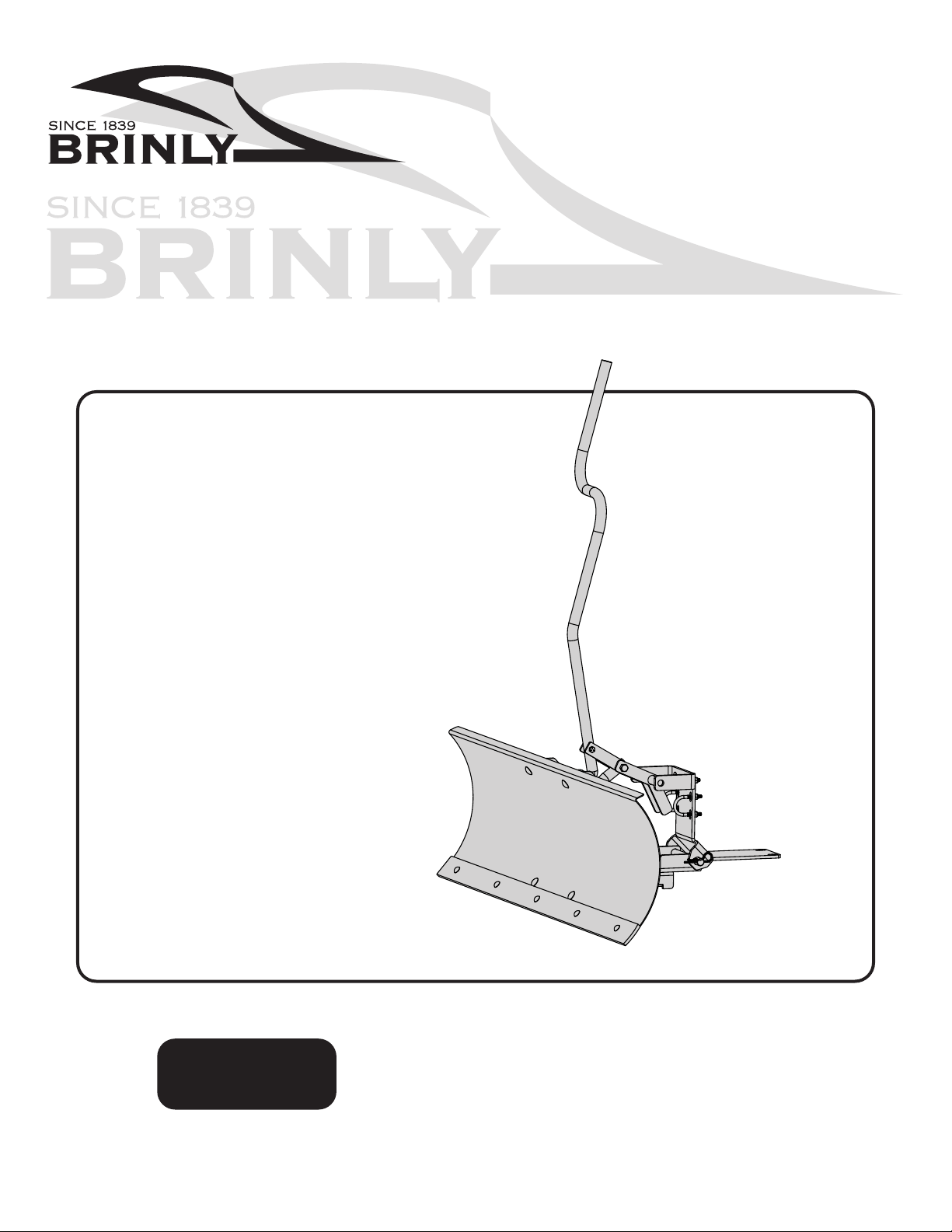
OWNER’S MANUAL
FRONT
MOUNT BLADE
MODEL:
FB-42RY
• Assembly
• Installation
• Operation
• Repair Parts
Visit us on the web!
www.brinly.com
Important: This manual contains information for the safety
of persons and property. Read it carefully before
assembly and operation of the equipment!
1
1018348-A
Page 2
INTRODUCTION
================================================================================================
Congratulations on the purchase of your new Brinly-Hardy Front-Mount Blade! This product has been designed, engineered and
manufactured to give you the best possible dependability and performance.
CUSTOMER
RESPONSIBILITIES
• Please read and retain this manual. The instructions enable you to assemble and
maintain your lawn spreader properly.
• Please carefully read and observe the SAFETY section of this manual.
• Follow a regular schedule in maintaining and caring for your Brinly-Hardy Spreader.
TABLE OF CONTENTS
SAFETY .......................... 2-3
PARTS LIST
AND REFERENCE ..................4-5
ASSEMBLY ....................... 7-15
OPERATION ..................... 16-17
STORAGE..........................18
MAINTENANCE .....................19
LIMITED WARRANTY.................20
RECORD PURCHASE INFORMATION
Record your purchase information in
the spaces provided below:
DATE OF PURCHASE _____________________________
COMPANY NAME _____________________________
COMPANY PHONE _____________________________
SERIAL NUMBER _____________________________
SAFETY
================================================================================================
This symbol will help to point out important
safety precautions throughout this manual. It
means: ATTENTION! BECOME ALERT! Your
safety is involved.
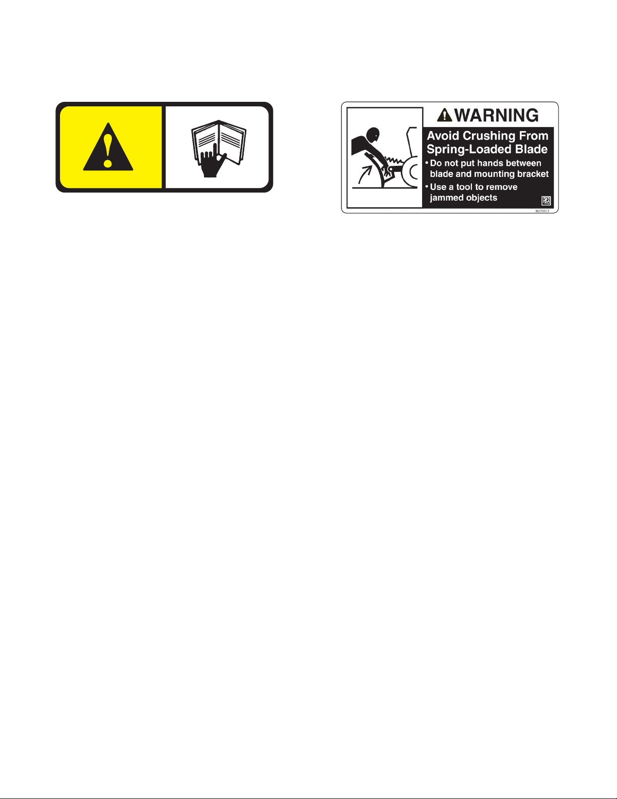
SAFETY LABELS AND NOTATION
The safety labels shown in this section are placed in important
areas on your product to draw attention to potential safety hazards.
On your product safety labels, the words DANGER, WARNING
and CAUTION are used with the safety-alert symbol. DANGER
identies the most serious hazards.
The operator’s manual also explains any potential safety hazards
whenever necessary in special safety messages that are identied
with the word, CAUTION, and the safety-alert symbol.
CAUTION: Keep feet and hands clear of
blade while raising and lowering the blade.
Pay close attention to your surrounding and
people in your immediate area at all times.
1018348-A
2
Page 3
SAFETY
================================================================================================
GENERAL NOTES (OPERATION)
Caution should be taken when using any attachment. This
attachment combined with the weight distribution, turning
radius, and speed of vehicle can result in severe injury or death
to operator, damage to vehicle, and/or attachment if not used
properly. Follow all safety precautions noted in the vehicle owner’s
manual, including the following precautions:
• Only use this product in the vehicle’s tow mode/speed setting
or less than 5 mph. Do not exceed 5 mph.
• Operating speed should always be slow enough to maintain
control. Travel slowly, using caution when traveling over rough
terrain. Avoid holes, rocks and roots.
• Slow down before you turn and do not turn sharply.
• Use caution when operating around retaining walls and other
raised embankments.
• Do not use attachment on steep slopes. A heavy load could
cause loss of control or overturn attachment and vehicle.
• Keep all movement on slopes slow and gradual. Do not make
sudden changes in speed, directions or turning.
• If you start and stop suddenly on hills, you may lose steering
control.
• Do not start or stop suddenly when going uphill or downhill.
Avoid uphill starts.
• Slow down & use extra care on hillsides. Use extreme caution
while operating near drop-offs.
• Do not drive close to creeks, ditches and public highways.
• Watch out for trafc when crossing roadways.
• Use care when loading or unloading the vehicle into a trailer
or truck.
• When reversing, back up straight using caution.
• Stop on level ground, disengage drives, set the parking brake,
and shut off engine before leaving the operator’s position for
any reason.
• Use this attachment for intended purpose only.
• Always wear substantial slip-resistant footwear. Do not wear
loose-tting clothing, tie back long hair and do not wear jewelry.
• Keep your eyes and mind on your vehicle, attachment and
area being covered. Do not let other interests distract you.
• Stay alert for holes and other hidden hazards in the terrain.
• Keep the vehicle and attachment in good operating condition
and keep safety devices in place.
• The vehicle and attachment should be stopped and inspected
for damage after striking a foreign object. Any damage should
be repaired before restarting and operating the equipment.
• Keep all parts in good condition and properly installed. Fix
damaged parts immediately. Replace worn or broken parts.
• Replace all worn or damaged safety and instruction decals.
Keep all nuts, bolts and screws tight.
• Do not modify the attachment or safety devices. Unauthorized
modications to the vehicle or attachment may impair its
function, safety and void the warranty.
VEHICLE AND ITS SAFETY
• Know your vehicle controls and how to stop safely. READ
YOUR VEHICLE OWNER’S MANUAL before operating.
• Check the vehicle’s brake action before you operate. Adjust or
service brakes as necessary.
• Stopping distance increases with speed and weight of load.
Travel slowly and allow extra time and distance to stop.
• Do not shift to neutral and coast downhill.
• Do not allow adults to operate the vehicle without proper
instruction or without having read the owner’s manual.
• Do not allow children to operate the vehicle.
PROTECT THOSE AROUND YOU
• Before you operate any feature of this attachment or vehicle,
observe your surroundings and look for bystanders.
• Keep children, bystanders and pets at a safe distance away
while operating this or any attachment.
• Use care when reversing. Before you back up, look carefully
behind for bystanders.
KEEP RIDERS OFF ATTACHMENT & VEHICLE
• Do not carry passengers.
• Do not let anyone, especially children, ride in/on this attachment,
the vehicle or mount bracket.
• Riders are subject to injury such as being struck by foreign
object and/or being thrown off during sudden starts, stops
and turns.
• Riders may also obstruct the operator’s view resulting in this
attachment being operated in an unsafe manner.
3
1018348-A
Page 4
PARTS LIST AND REFERENCE
================================================================================================
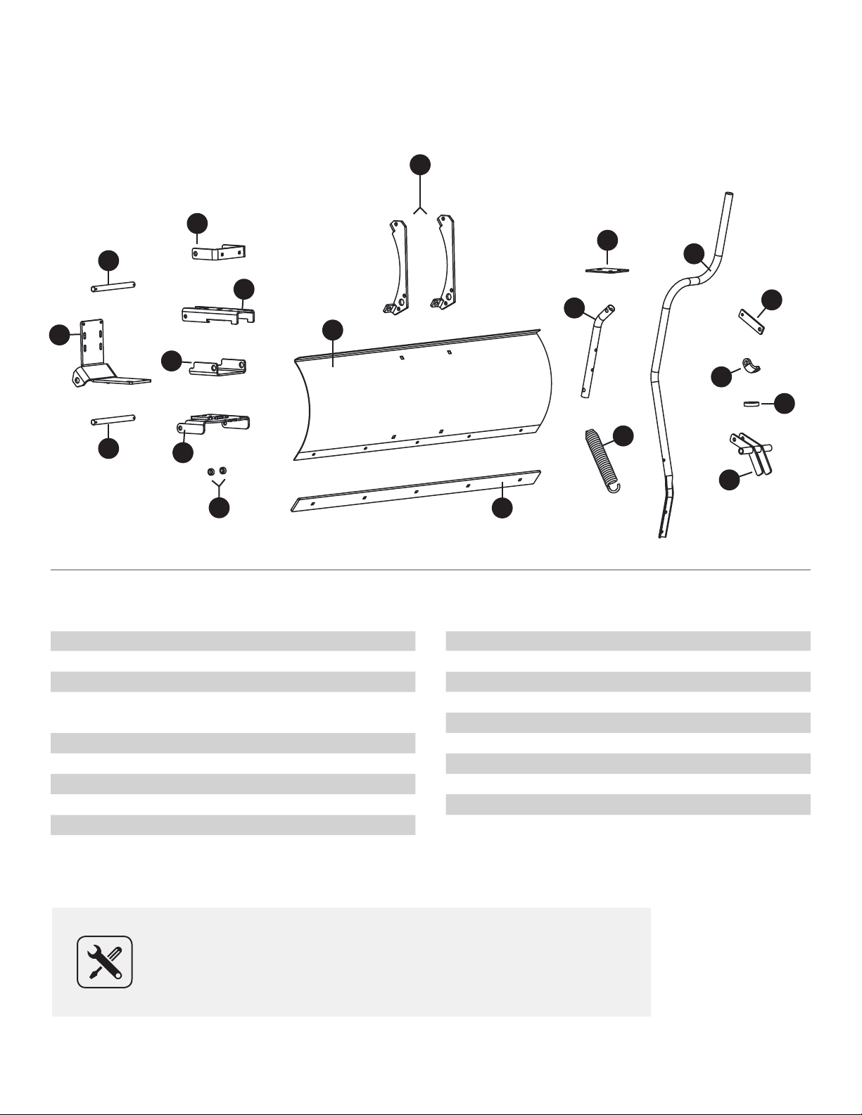
EXPLODED VIEW
5
1
2
7
3
8
10
13
6
14
11
15
9
12
16
17
18
19
20
REF PART NO. DESCRIPTION QTY
1 1017741-01 Rod, Hinge Plated 1
2 1017835-10 Painted Mount, Front 1
3 1018092-01 Rod, Transport Plated 1
1018104 Hardware Bag * 1
4
1018352 Parts Bag * 1
5 1018105-10 Painted Bracket, Pivot 1
6 1018109-10 Painted Bracket, Lower PV 1
7 1018110-10 Painted, Bracket Up Pivot 1
8 10 18111-10 Painted, Hinge Weldment 1
9 1018115-01 Tube, Pivot Plated 2
10 1018116-10 Ribs, Painted 2
• 3/4” Socket & Wrench
Tools Required
for Assembly:
• 9/16” Socket & Wrench
• 1/2” Socket & Wrench
• 7/16” Socket & Wrench
REF PART NO. DESCRIPTION QTY
11 1018347 Blade, 42” 1
12 1018118-10 Wear Bar, 42” Painted 1
13 1018119-10 Painted Plate, Bottom 1
14 1018120-10 Painted Tube, Raise 1
15 1018121 Trip Spring 1
16 1018122-10 Painted Tube, Handle 1
17 1018123 -10 Painted Plate, Handle 1
18 B-7215 -10 Spring Bracket 1
19 B-723P-01 Thick Washer, 3/8” 1
20 1018106-10 Painted Cam Weldment 1
* Not shown
• 12 mm Wrench
• Ratchet Wrench
• Pliers
• Gloves
1018348-A
4
Page 5
PARTS LIST AND REFERENCE
================================================================================================
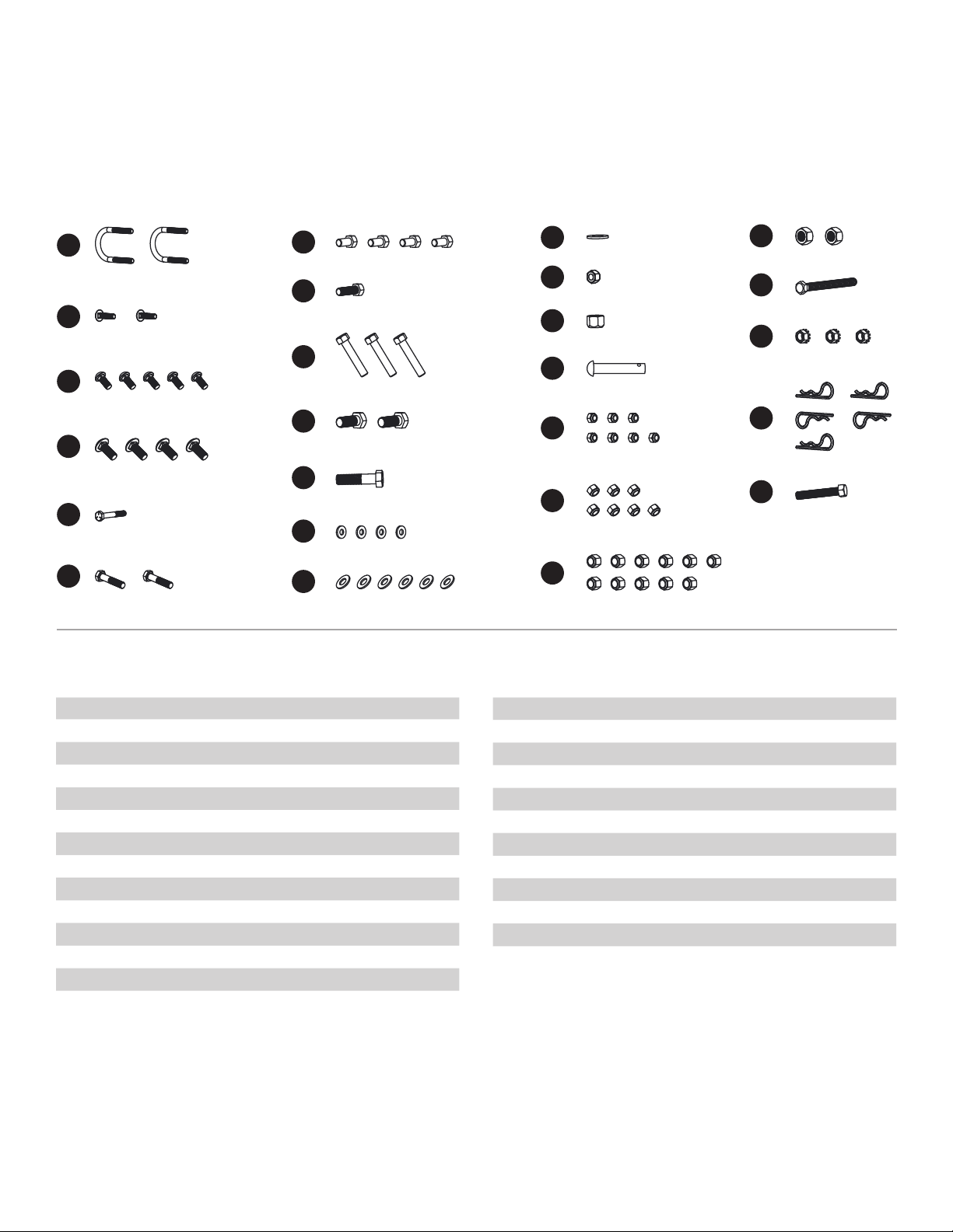
EXPLODED VIEW - HARDWARE BAG
22
23
24
25
26
27
28
29
30
31
32
33
34
REF PART NO. DESCRIPTION QTY
35
36
37
38
39
40
41
42
43
44
45
46
REF PART NO. DESCRIPTION QTY
21 1000225 Handle Grip * 1
22 1017742 U-bolt 2
23 11M0 816 P Bolt, Carriage 1/4" x 1" 2
24 11M1012 P Bolt, Carriage 5/16 x 3/4 5
25 11M1216 P Bolt, Carrige 3/8 x 1 4
26 2M0828P Bolt, Hex Head 1/4 x 1-3/4 1
27 2M1024P Bolt, Hex Head 5/16 x 1-1/2 2
28 2M1212P Bolt, Hex Head 3/8 x 3/4 4
29 2M1220P Bolt, Hex Head 3/8 x 1-1/4 1
30 2M1232P Bolt, Hex Head 3/8 x 2 3
31 2M1620P Bolt, Hex Head 1/2 x 1-1/4 2
32 2M1632P Bolt, Hex Head 1/2 x 2 1
33 45M0909P Washer, SAE Flat, 1/4" 4
34 45M1313P Washer, SAE Flat-3/8 6
35 45M1717P Washer, Flat 1/2" 1
36 B-1675P Nut, Hex Lock, 3/8"-16 2
37 B-1677P Nut, Hex Lock, 1/2"-13 1
38 B-3861 Pin, Hitch 1/2" X 2-1/2" 1
39 B-4785 Nut, Nylon Lock 1/4-20 7
40 B-4786 Nut, Nylon Lock 5/16-18 7
41 B-4820 Nut, Nylon Lock, 3/8"-16 11
42 B-5096Y Nut, Nylon Lock, 1/2"-13 2
43 B-6298 Bolt, Hex Hd 3/8 x 3-3/4 1
44 B-6299 Nut, Keps Hex, 3/8-16 3
45 D-146P Hairpin Cotter, 1/8”, #211 5
46 B-7291 Bolt, 3/8 x 2-1/2 1
* Not shown
5
1018348-A
Page 6
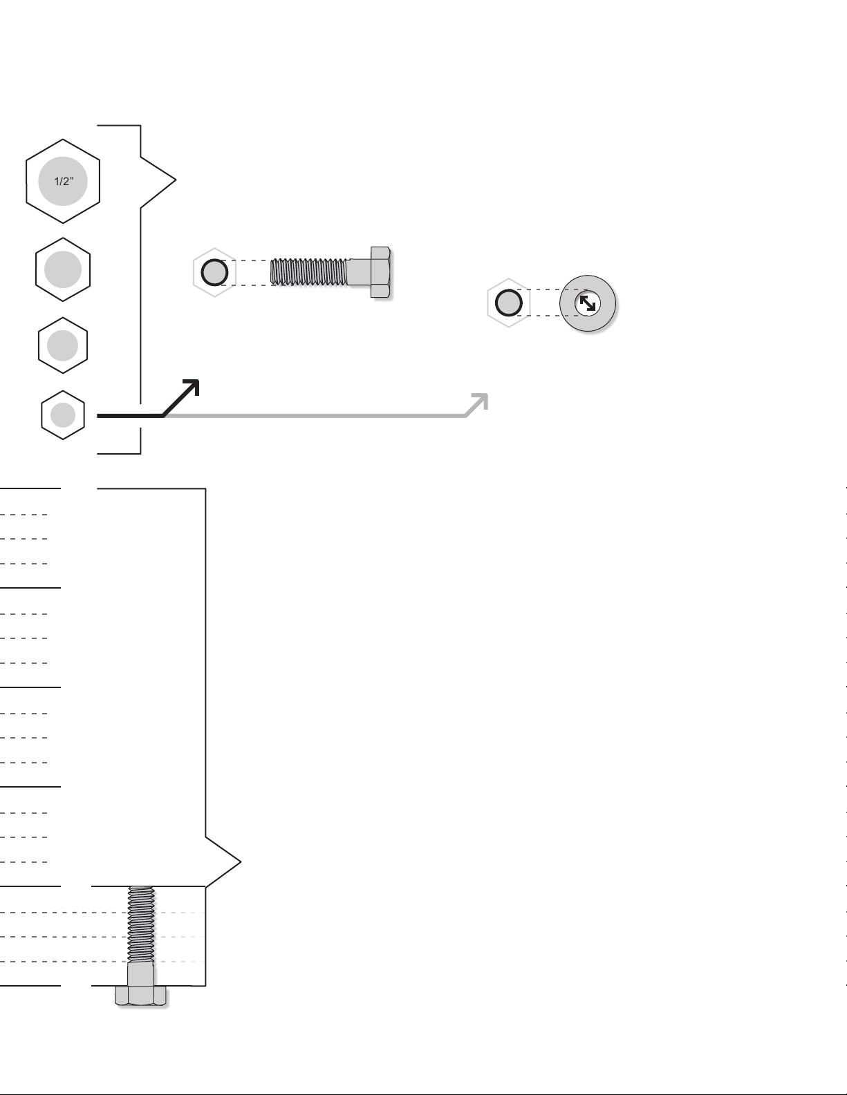
Each spread of the assembly has a guide to help with hardware identication.
1/2”
3/8”
5/16”
1/4”
THIS SECTION CAN BE USED
TO IDENTIFY BOLTS:
**
Check the bolt size by placing the
head or the threaded end over the
matching diagrams to the left.
THIS SECTION CAN ALSO
ASSIST WITH IDENTIFYING
WASHERS:
Exterior circumference of washers
can vary. These dimensions are a
measurement of the internal diameter
of the washer.
1/4”
**
Example =
Hex Head Bolt
1/4” x 1”
**
**
5”
1/4”
Example =
1/4” Washer
4”
3”
2”
THIS SECTION CAN BE
USED TO IDENTIFY BOLTS:
Check the bolt length by measuring the
1”
0”
Example =
Hex Head Bolt
1/4” x 1”
length of each bolt with this ruler.
6
Page 7
ASSEMBLY
=========================================================================================
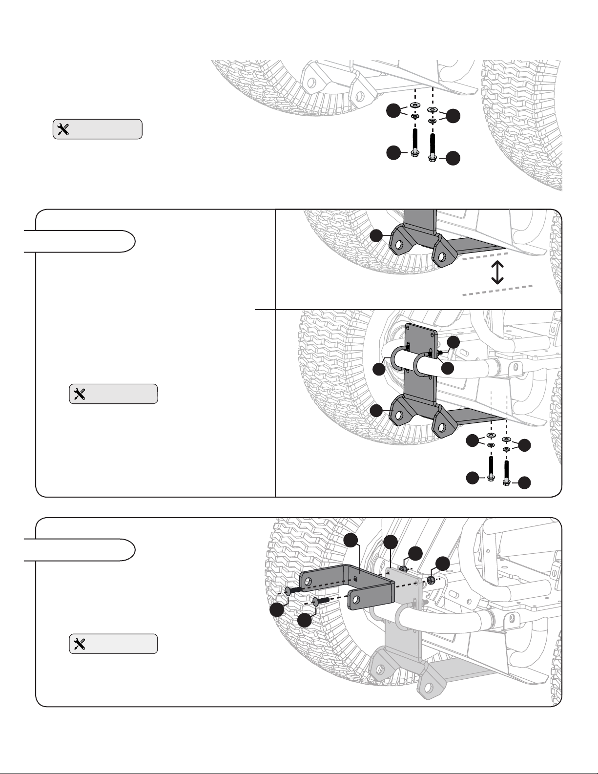
For the rst step, you’ll need
to remove hardware from the front
of your mower.
12mm Wrench
B
B
Assembly Step 1
Unscrew the two skid plate bolts (A)
and two sets of washers (B).
1. Loosely start to attach the mounting
plate (2) to your mower by reusing the
removed hardware (A & B) as well as
U-bolts found in the hardware bag:
- x 2 U-Bolts (22)
- x 4 Washers (33) – 1/4”
- x 4 Lock Nuts (39) – 1/4”
7/16” Wrench
2. Align the bottom of the mounting plate (2)
parallel to the ground and make sure the
front of the mounting plate is touching the
inside edge of the bumper tubing. Tighten
all hardware.
A
2
The bottom of the mounting
plate (2) needs to be parallel to the ground.
22
2
33
39
A
B
A
B
A
Assembly Step 2
3. Attach pivot bracket (5) to the
mount plate (2) using:
- x 2 Carriage Bolts (23) – 1/4” x 1”
- x 2 Lock Nuts (39) – 1/4”
7/16” Wrench
23
5
23
7
2
39
39
1018348-A
Page 8
ASSEMBLY
================================================================================================
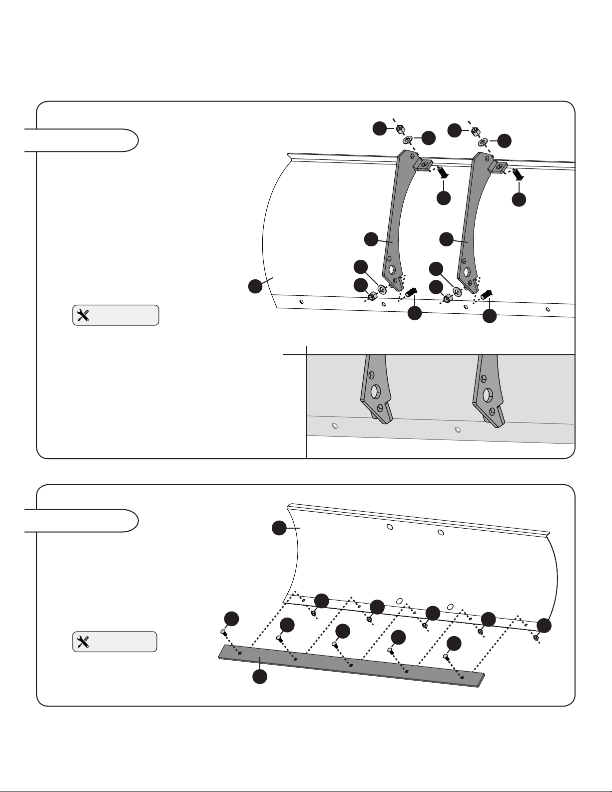
Assembly Step 3
Blade Assembly
1. Attach ribs (10) to the
blade (11) using:
- x 4 Carriage Bolts (25) – 3/8” x 1”
- x 4 Washers (34) – 3/8”
- x 4 Lock Nuts (41) – 3/8”
Note: Do not fully tighten (yet),
these ribs may need to shift slightly
during Assembly Step 10.
9/16” Wrench
11
Note: Ensure the ribs (10) are
aligned correctly. The ends with
three small cutouts on the rib
need to be at the base of the
blade. See illustration:
41
10 10
34
41
25
34
34
41
25
41
34
25
25
Assembly Step 4
Blade Assembly
2. Attach wear bar (12) to bottom
of blade (11) using:
- x 5 Carriage Bolts (24) – 5/16” x 3/4”
- x 5 Lock Nuts (40) – 5/16”
1/2” Wrench
1018348-A
24
12
11
24
40
24
40
24
40
24
40
40
8
Page 9
ASSEMBLY
================================================================================================
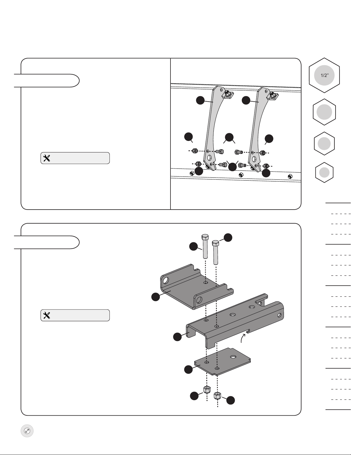
Assembly Step 5
Blade Assembly
3. Install bolt and nut stops to the blade ribs (10) using:
- x 4 Hex Head Bolts (28) – 3/8” x 3/4”
- x 4 Lock Nuts (41) * – 3/8”
*Note: Nuts need to be on the outside
edges of the blade ribs.
9/16” Wrench & Socket
4. Set blade aside.
Assembly Step 6
10 10
41
41
30
30
28
28
41
1/2”
**
3/8”
**
41
5/16”
**
1/4”
**
5”
4”
Push Arm Assembly
1. Attach upper push bracket (7)
to lower push bracket (6) and bottom
plate (13) using:
- x 2 Hex Head Bolts (30) – 3/8” x 2”
- x 2 Nylon Lock Nuts (41) – 3/8”
9/16” Wrench & Socket
**Exterior circumference of washers can vary.
These dimensions are a measurement of the
internal diameter of the washer.
3”
7
2”
6
13
41
41
9
1”
0”
1018348-A
Page 10
ASSEMBLY
================================================================================================
1/2”
3/8”
5/16”
1/4”
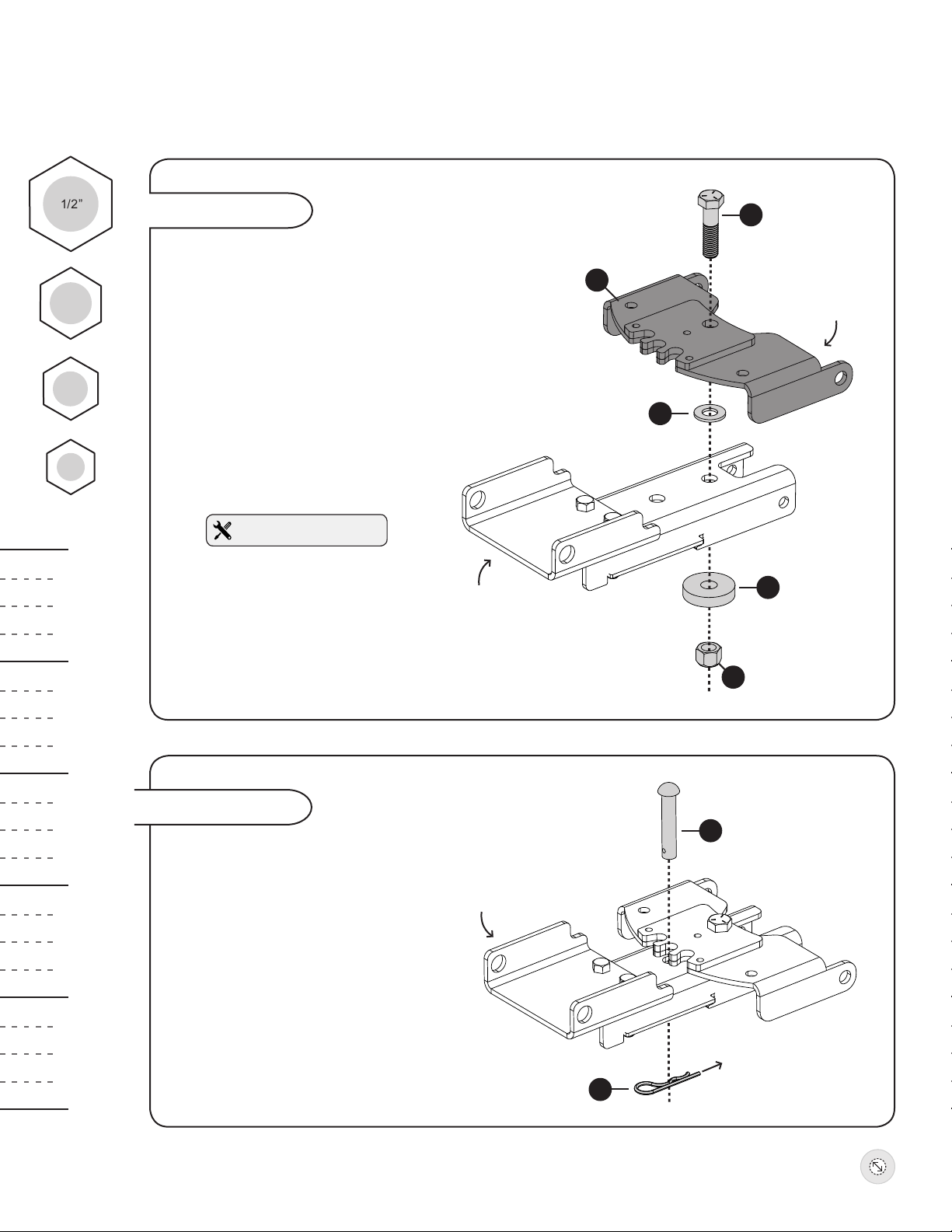
Assembly Step 7
**
32
Push Arm Assembly
2. Attach pivot weldment (8) to the push
8
**
arm assembly using:
pivot
weldment
- x 1 Hex Head Bolt (32) – 1/2” x 2”
- x 1 Washer, Flat (35) – 1/2”
- x 1 Washer, Thick (19)
- x 1 Lock Nut, Hex (37) – 1/2”
**
NOTE: Do not over tighten,
35
the two brackets should be able
to move freely of one each other,
**
5”
but not so loose that there is play
in the joint.
3/4” Wrench & Socket
push arm
assembly
20
4”
3”
37
Assembly Step 8
38
Push Arm Assembly
2”
3. Drop hitch pin (38) into the
center hole of the push arm
assembly and secure with a
hairpin (45).
1”
0”
push arm
assembly
45
1018348-A
10
**Exterior circumference of washers can vary.
These dimensions are a measurement of the
internal diameter of the washer.
Page 11
ASSEMBLY
================================================================================================
10 1010 10
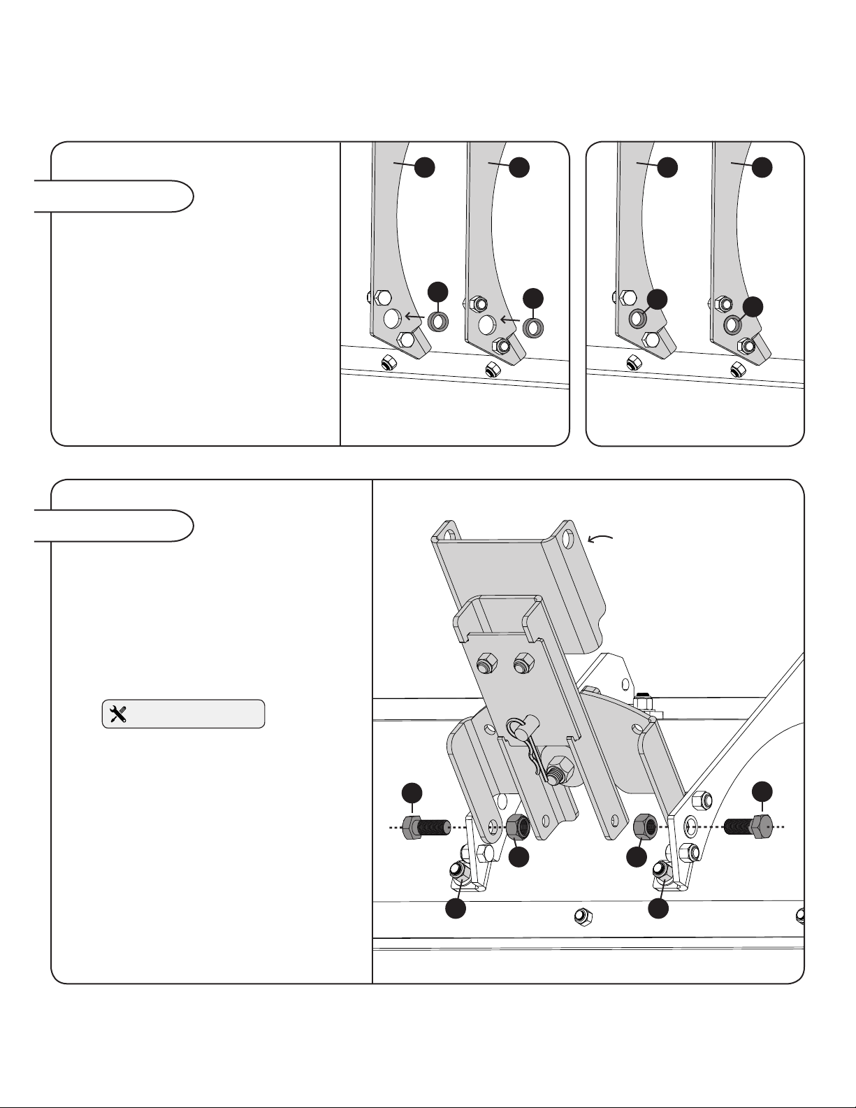
Assembly Step 9
Joining the Push Arm
to the Blade
1. Insert spacer / pivot tube (9)
into the large holes on the lower
part of the ribs (10) on the back
of the blade.
Assembly Step 10
Joining the Push Arm
to the Blade
2. Slide push arm assembly between ribs
and align with the pivot tubes that were
inserted on Step 9. Attach using:
- x 2 Hex Head Bolts (31) – 1/2” x 1 1/4”
- x 2 Nylon Lock Nuts (42) – 1/2”
9
9
9-A 9-B
9
push arm
assembly
9
3. Tighten the ribs to the
3/4” Wrench & Socket
blade completely. (41).
31
42 42
41 41
11
31
1018348-A
Page 12
ASSEMBLY
================================================================================================
1/2”
3/8”
5/16”
1/4”
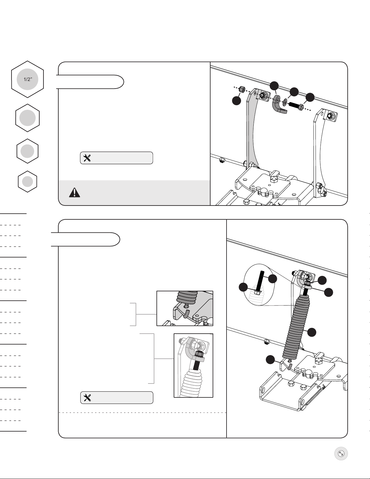
Assembly Step 11
**
Joining the Push Arm
41
18
34
29
to the Blade
**
3. Attach spring trip bracket (18) using:
- x 1 Hex Head Bolt (29) – 3/8” x 1 1/4”
- x 1 Washer, Flat (34) – 3/8”
- x 1 Lock Nut (41) – 3/8”
**
**
5”
9/16” Wrench & Socket
DO NOT tighten completely (yet).
Assembly Step 12
4”
Joining the Push Arm to the Blade
4. Mount trip spring by treading 3/8” x 2 1/2” full
threaded bolt (46) and 3/8” washer (34) so that the
head of the bolt is captured
inside of spring (15).
3”
5. Hook the opposite
34
46
44
18
end of the spring
(15) through the
pivot weldment (8).
6. Insert the bolt through
2”
the trip bracket (18) that
was installed on Assembly
Step 11.
Tread and tighten the 3/8”
8
15
toothed nut (44) until the
spring is touching the
bracket.
1”
9/16” Wrench & Socket
7. Tighten the nut and bolt that were added
0”
on Assembly Step 11.
1018348-A
12
**Exterior circumference of washers can vary.
These dimensions are a measurement of the
internal diameter of the washer.
Page 13
ASSEMBLY
================================================================================================
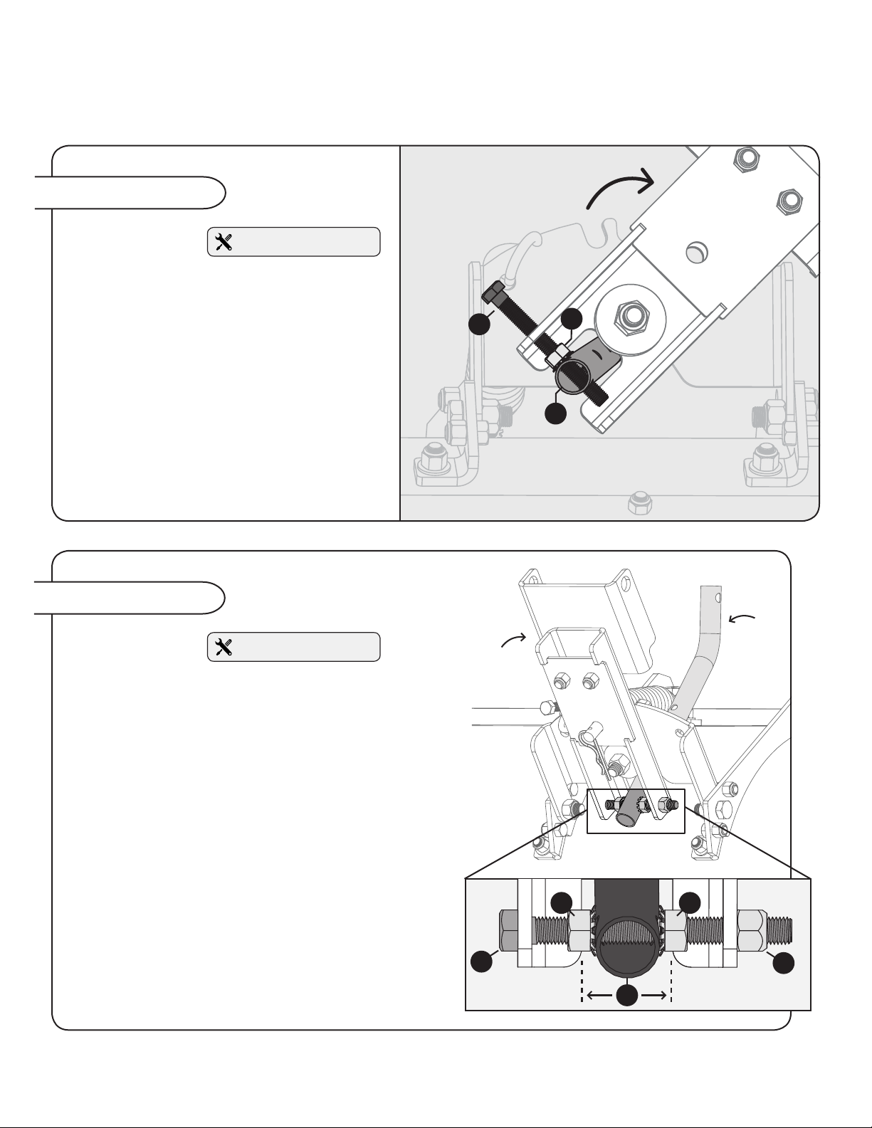
Assembly Step 13-A
Adding the Handle
1. Temporarily remove the drop hitch pin (38)
from Assembly Step 8 and rotate the push
arm assembly away from the spring.
2. Run a hex head bolt, 3/8” x 3 3/4” full thread
(43) through the rst hole of the push arm
assembly & add:
- x 1 Hex Nut (44) – 3/8” External-teeth
facing the lower handle tube.
3. Align the lower handle tube (14) and
continue to run the hex head bolt (43)
through the handle.
9/16” Wrench & Socket
Assembly Step 13-B
Adding the Handle
9/16” Wrench & Socket
43
push arm
assembly
43
43
lower
handle
tube
4. Rotate the push arm assembly back to center and
replace the drop hitch pin (38) from Assembly Step 8.
5. After the bolt (43) extends through the tube, add:
- x 1 Hex Nut (44) – 3/8”
External-teeth facing the lower handle tube.
6. Continue running the bolt (43) through the push arm
assembly. Secure in place using:
- x 1 Lock Nut (36) – 3/8”
7. Use the two Hex Nuts (44) to center and secure
in place the lower handle tube (14) within the opening
of the push arm assembly. (See detail to the right).
13
43
44
44
36
14
1018348-A
Page 14
ASSEMBLY
================================================================================================
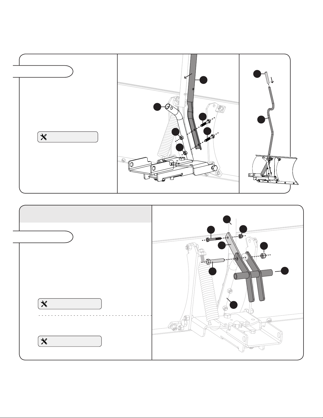
Assembly Step 14
Adding the Handle
4. Attach the upper handle
tube (16) to the lower handle
tube (14) using:
- x 2 Bolts (27) – 5/16” x 1 1/4”
- x 2 Lock Nuts (40) – 5/16”
1/2” Wrench & Socket
5. Slid grip (20) over the end of the
upper handle tube (16).
DO NOT TIGHTEN FULLY. This part needs to pivot.
14
40
40
27
20
16
16
27
16
Assembly Step 15
Reinforcement Bracket
1. Attach the reinforcement bracket (17) and
pivot weldment (20) to both of the handle
tubes, upper (16) and lower (14), using:
x 1 Bolt (26) – 1/4” x 1 3/4”
+ x 1 Lock Nut (39) – 1/4”
x 1 Bolt (30) – 3/8” x 2”
7/16” Wrench & Socket
+ x 1 Lock Nut (36) – 3/8”
9/16” Wrench & Socket
26
30
17
39
36
20
14
1018348-A
14
Page 15
ASSEMBLY
push arm
assembly
mower
bracket
45
45
1
================================================================================================
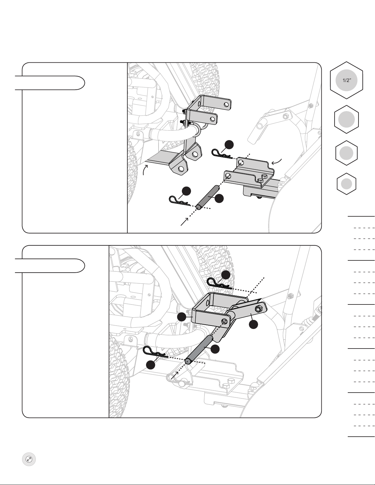
Assembly Step 16
Mounting the Blade
1. Face the back of the
blade assembly toward
the bracket that you
added to your mower
in Assembly Steps 1-2.
2. The push assembly will
easily slide within the lower
tabs extending from the
mower bracket.
3. After aligning the
two sets of bracket holes,
insert the plated hinge rod /
pin (1) and secure with two
hairpin cotters (45), one on
each end.
1/2”
**
3/8”
**
5/16”
**
1/4”
**
5”
Assembly Step 17
Mounting the Blade
4. Line up pivot
weldment (20)
with the pivot
bracket (5) and
insert pin (3).
5. Secure with two
hairpin cotters (45).
**Exterior circumference of washers can vary.
These dimensions are a measurement of the
internal diameter of the washer.
45
4”
45
3”
5
20
3
15
2”
1”
0”
1018348-A
Page 16
OPERATION
============================================================================================
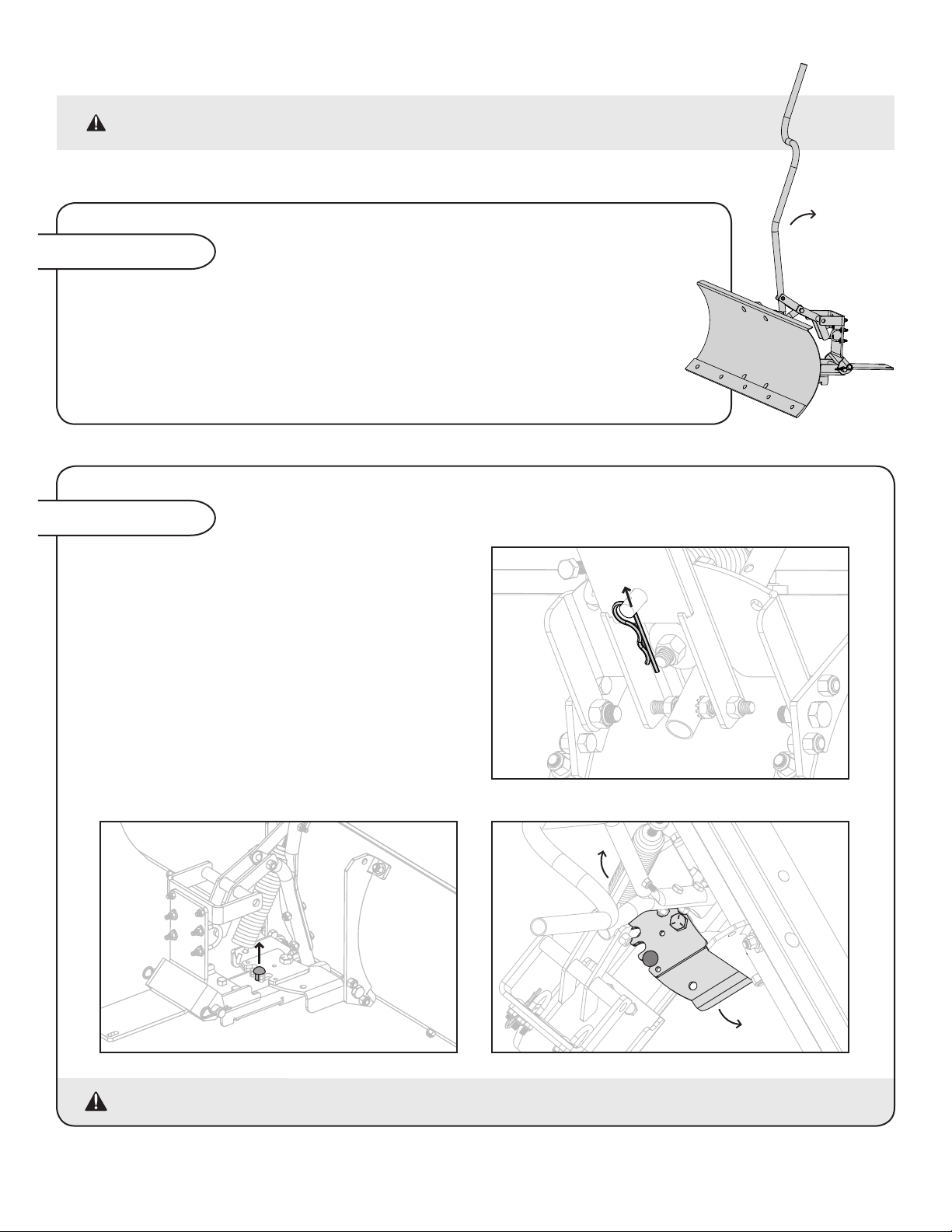
CAUTION: Keep feet and hands clear of blade while raising and lowering the blade.
Pay close attention to your surrounding and people in your immediate area at all times.
Operation Step 1
Transport Position
1. To raise your blade into transport position, pull the upper handle toward operator.
Note: Ensure the handle has been pulled back far enough to engage the
self-locking feature.
pull toward
operator
Fig 1
Operation Step 2
Changing the Blade Angle
1. Turn key switch off & engage parking brake, then lower
the blade to the ground.
2. Simply remove the hair pin beneath the push assembly
arm (see g 2.1) and pull hitch pit out (g 2.2).
3. Rotate blade to desired location (g 2.3).
4. Replace the hitch pin and secure hair pin underneath in
order to to lock the blade in position.
Fig 2.2
Fig 2.1
Fig 2.3
NOTE: Do not adjust angle of blade while in transport position.
1018348-A
16
Page 17
OPERATION
============================================================================================
CAUTION: Keep feet and hands clear of blade while raising and lowering the blade.
Pay close attention to your surrounding and people in your immediate area at all times.
CAUTION
1. INSPECT THE AREA
Before operating the snow blade, inspect the area to be worked carefully. Avoid curbs and other
heavy obstructions.
2. KNOW THE TERRAIN
Avoid exceptionally sharp slopes or drop offs which may be hidden by the snow, never run the
snow blade into heavy material at high speed.
3. LOWER THE BLADE
Always lower blade to ground before leaving mower
4. START SLOW
Always begin at low speeds and gradually increase as required. Do not exceed 5 mph.
Do not attempt to move snow all in the same direction, causing an excessive buildup, which would
become larger with each pass.
5. RAISE THE BLADE
Raise blade when moving in reverse
6. SNOW REMOVAL
The blade is intended for snow removal only
17
1018348-A
Page 18
STORAGE
============================================================================================
CAUTION: Keep feet and hands clear of blade while raising and lowering the blade.
Pay close attention to your surrounding and people in your immediate area at all times.
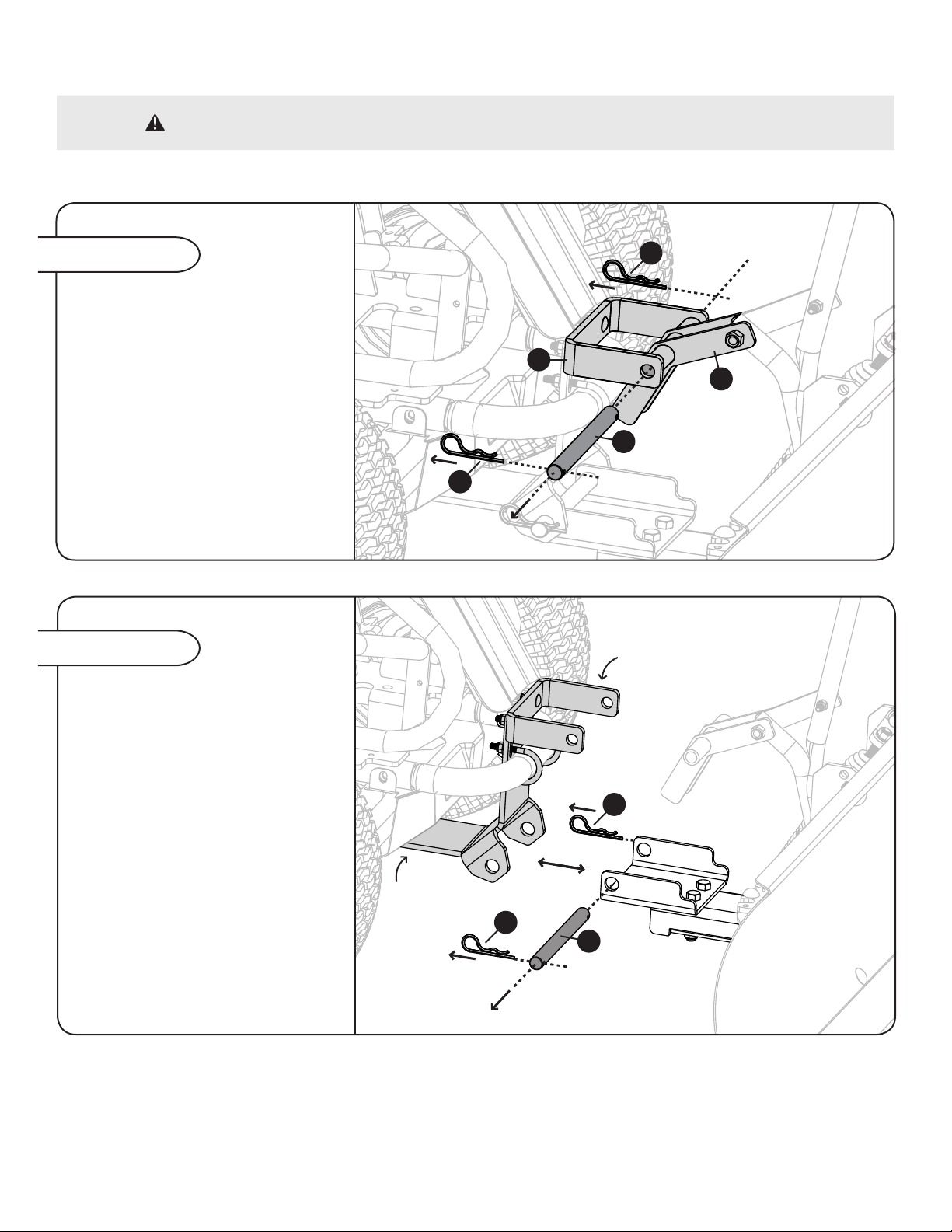
Storage Step 1
Removing Blade
1. Turn key switch off and
engage the parking brake, then
lower the blade to the ground.
2. Remove the two hairpin
cotters (45).
3. Remove the pin (3) from the
pivot weldment (20) and pivot
bracket (5).
Storage Step 2
Removing Blade
45
5
20
3
45
pivot
bracket
4. Set aside the two hairpin
cotters (45) from each end
and remove the plated hinge
rod / pin (1).
5. The push arm assembly
and mower bracket will
easily separate.
6. Leave the mounting and
pivot brackets attached to
the mower.
1018348-A
45
mounting
bracket
45
1
18
Page 19

MAINTENANCE
================================================================================================
CAUTION: Keep feet and hands clear of blade while raising and lowering the blade.
Pay close attention to your surrounding and people in your immediate area at all times.
1. CLEAN AND DRY
The key to years of trouble-free service is to
keep you plow clean and dry
2. MOVING PA RTS
After the rst 30 minutes of use, check all of the
fasteners for tightness. Thereafter, periodically
check all fasteners for tightness.
3. MOVEMENT
Check all moving parts for free movement and if
necessary, lubricate with oil.
4. BUILD-UP
Periodically remove debris build up
5. RUST
For rust appearing on painted surfaces, sand
lightly and point affected area with enamel.
6. ROTATION
After the wear bar has worn considerably, it
should be rotated (from bottom to top) to provide
a “new” edge. Remove the ve carriage bolts
(5/16”), rotate the blade, and then reassemble
the unit with the “new” edge on the surface.
19
1018348-A
Page 20

Brinly-Hardy Company, 3230 Industrial Parkway, Jeffersonville, IN 47130 (877) 728-8224
MANUFACTURER’S LIMITED WARRANTY
FOR
Accessories
THIS IS A COPY OF OUR EXISTING WARRANTY IF
YOU WOULD LIKE TO USE IT FOR REFERENCE:
The limited warranty set forth below is given by Brinly-Hardy
Company with respect to new merchandise purchased and used
in the United States, its possessions and territories.
Brinly-Hardy Company warrants the products listed below against
defects in material and workmanship, and will at its option, repair
or replace, free of charge, any part found to be defective in
materials or workmanship. This limited warranty shall only apply
if this product has been assembled, operated, and maintained
in accordance with the Operator’s manual furnished with the
product, and has not been subject to misuse, abuse, commercial
use, neglect, accident, improper maintenance, alteration,
vandalism, theft, re, water, or damage because of other peril or
natural disaster.
Normal Wear Parts or components thereof are subject to separate
terms as follows: All normal wear parts or component failures will
be covered on the product for a period of 90 days.
Parts found to be defective within the warranty period will be
replaced at our expense. Our obligation under this warranty is
expressly limited to the replacement or repair, at our option, of
parts found to be defective in material and workmanship.
HOW TO OBTAIN SERVICE: Warranty parts replacements
are available, ONLY WITH PROOF OF PURCHASE, through our
Customer Service Department. Call 877-728-8224.
This limited warranty does not provide coverage in the following
cases:
a) Routine maintenance items such as lubricants and lters.
b) Normal deterioration of the exterior nish due to use or
exposure.
c) Transportation and/or labor charges.
d) The warranty does not include commercial and/or rental use.
No implied warranty, including any implied warranty of
merchantability of tness for a particular purpose, applies
after the applicable period of express written warranty above
as to the part as identied below. No other express warranty
whether written or oral, except as mentioned above, given
by any person or entity, including a dealer or retailer, with
respect to any product, shall bind Brinly-Hardy Co. During
the period of the warranty, the exclusive remedy is repair or
replacement of the product as set forth above.
The provisions as set forth in this warranty provide the sole
and exclusive remedy arising from the sale. Brinly-Hardy Co.
shall not be liable for incidental or consequential loss or
damage including, without limitation, expenses incurred for
substitute or replacement lawn care services or for rental
expenses to temporarily replace a warranted product.
Some states do not allow the exclusion or limitation of incidental
or consequential damages, or limitations on how long an implied
warranty lasts, so the above exclusions or limitations may not
apply to you.
During the warranty period, the exclusive remedy is replacement
of the part. In no event shall recovery of any kind be greater that
the amount of the purchase price of the product sold. Alteration
of safety features of the product shall void this warranty. You
assume the risk and liability for loss, damage, or injury to you and
your property and/or to others and their property arising out of the
misuse or inability to use this product.
This limited warranty shall not extend to anyone other than the
original purchaser or to the person for whom it was purchased as
a gift.
HOW STATE LAW RELATES TO THIS WARRANTY: This
limited warranty gives you specic legal rights, and you may also
have other rights which vary from state to state.
IMPORTANT: The Warranty period stated below begins with
the PROOF OF PURCHASE. Without the proof of purchase, the
Warranty period begins from the date of manufacture determined
by the serial number manufacturing date.
WARRANTY PERIOD:
The warranty period for the product shown in this manual is as
follows: Steel Frame Parts: 2 Years. Tires, Wheels and Drive are
normal wear parts – 90 days.
1018348-A
20
 Loading...