

Page 1
Visit us on the web!
www.brinly.com
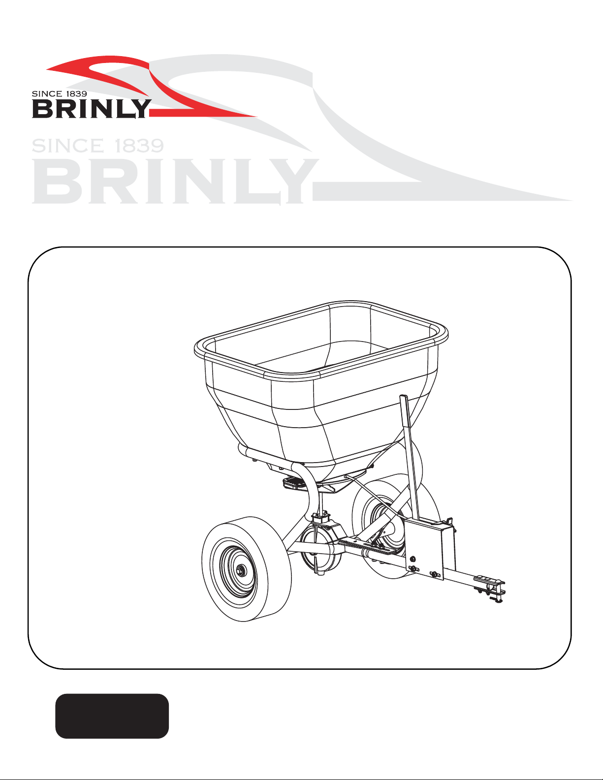
OWNER’S MANUAL
BROADCAST SPREADER
MODEL:
BS-36
BS-26
• Assembly
• Installation
• Operation
• Repair Parts
For use with Riders
and Lawn/Garden Tractors.
For the latest product updates & setup tips:
Important: This manual contains information for the safety of
persons and property. Read it carefully before assembly and
operation of the equipment!
L-1884-C
Page 2
INTRODUCTION
CONGRA TULATIONS on your new Brinly-Hardy Broadcast Sp reader!
Your Spreader has been designed, engineered and manufactured to
give you the best possible dependability and performance.
Should you experience any problem you can not easily remedy,
please do not hesitate to contact our knowledgeable customer service
department toll-free at 1-877-728-8224. We have competent, well
trained technicians to help you with the assembly and use of your
spreader.
CUSTOMER RESPONSIBILITIES
Please read and retain this manual. The instructions enables you to
assemble and maintain your broadcast spreader properly. And
please, always observe the “Safety” instructions.
Follow a regular schedule in maintaining, caring-for and using your
Brinly-Hardy Broadcast Spreader.
TABLE OF CONTENTS
PRODUCT IDENTIFICATION............................................2
SAFETY ............................................................................ 3
PARTS REFERENCE .......................................................4
PARTS LIST ...................................................................5-6
ASSEMBLY .................................................................. 7-17
CALIBRATION .................................................................18
OPERATION ................................................................... 19
ANNUAL MAINTENANCE ..........................................20-23
MEDIA FLOW SETTINGS ..........................................24-26
TROUBLESHOOTING.....................................................27
SPECIFICATIONS ..........................................................27
WARRANTY........................................................Back Page
Safety-Alert Symbol
The machine safety labels shown in this section are placed in important areas on your machine to draw attention to potential safety hazards.
On your machine safety labels, the words DANGER, WARNING , and
CAUTION are used with this safety-alert symbol. DANGER identifies
the most serious hazards.
The operator's manual also explains any potential safety hazards
whenever necessary in special safety messages that are identified
with the word, CAUTION, and the safety-alert symbol.
PRODUCT IDENTIFICATION
PRODUCT COMPATIBLIITY
This broadcast spreader is designed for use with riders and lawn and
garden tractors.
RECORD PURCHASE INFORMATION
Record your purchase information in the spaces provided below.
DATE OF PURCHASE: ___________________________
COMPANY NAME: ______________________________
COMPANY PHONE: _____________________________
SERIAL NUMBER: ______________________________
SAFETY LABELS
UNDERSTANDING THE MACHINE SAFETY LABELS
Please read and retain this manual. The instructions will enable you to
assemble and maintain your broadcast spreader properly. And
please, always observe the “Safety Rules”.
2.
L-1884-C
Page 3

SAFETY
Read the general safety operating precautions in your towing vehicle
operator's manual for additional safety information.
Operate Safely
Use this machine for intended purpose only.
This machine is intended for use in lawn care and home applications.
Do not tow behind a vehicle on a highway or in any high speed applications. Do not tow at speeds higher than maximum recommended
towing speed.
Towing speed should always be slow enough to maintain control.
Travel slowly over rough ground.
Do not let children or an untrained person operate machine.
Do not let anyone, especially children, ride on this machine or the tow-
ing vehicle. Riders are subject to injury such as being struck by foreign
objects and being thrown off. Riders may also obstruct the operator's
view, resulting in this machine being operated in an unsafe manner.Check towing vehicle brake action before you operate. Adjust or
service brakes as necessary.
Keep all parts in good condition and properly installed. Fix damaged
parts immediately . Replace worn or broken parts. Replace all worn or
damaged safety and instruction decals.Do not modify the machine or
safety devices. Unauthorized modifications to the towing vehicle or
machine may impair its function and safety, and void the warranty.
Keep all nuts, bolts and screws tight.
SAFETY RULES
• Know controls and how to stop quickly, READ THE VEHICLE OWNER'S MANUAL.
• Do not allow children to operate the vehicle, do not allow
adults to operate without proper instruction or without
having read the owner's manual.
• Do not carry passengers. Keep children and pets a safe
distance away.
• Keep all nuts, bolts and screws tight to be sure the equipment is in safe working condition.
• The vehicle and attachment should be stopped and
inspected for damage after striking a foreign object. The
damage should be repaired before restarting and operating the equipment.
• When backing - carefully back straight to avoid jack knifing, which could result in damage to equipment.
• Maximum load is 175 lbs for a BST-36 and 125 lbs. for a
BST-26.
• Maximum speed - 3 mph.
• Maintain broadcast spreader tires inflated to 20 psi.
• This attachment is intended for lawn care. Do not tow
behind a vehicle on a highway.
• Avoid tipping and skidding.
• Avoid holes, rocks and roots.
• Slow down before you turn.
• Keep riders off of hitch bracket.
Operating Hints
Always operate your spreader with the speed limit for which it was
designed - 3 MPH.
When backing - carefully back straight to avoid jack knifing which
could result in damage to equipment.
Only tow your spreader behind vehicles for which it was designed riders, lawn/garden tractors. DO NOT TOW this spreader behind high
speed equipment such as A TV's, R TV's, or Pick up trucks.
Do not load the hopper with more than the maximum weight capacity
of 175 pounds for BST-36 and 125 pounds for BST-26.
• Always wear substantial footwear. Do not wear loose fitting clothing that can get caught in moving parts.
• Use only approved hitches. Tow only with a machine that
has a hitch designed for towing. Do not attach this
machine except at the approved hitch point.
• Keep your eyes and mind on your vehicle and attachment. Do not let other interests distract you.
• Stay alert for holes in the terrain and other hidden hazards.
• Do not drive close to creeks, ditches and public highways.
• Watch out for traffic when crossing or near roadways.
• When using any attachment, don't allow anyone near the
vehicle while in operation.
• Before you operate any feature of this machine, observe
your surroundings and look for bystanders.
• Always wash hands after contact with fertilizers and pesticides.
L-1884-C 3.
Page 4
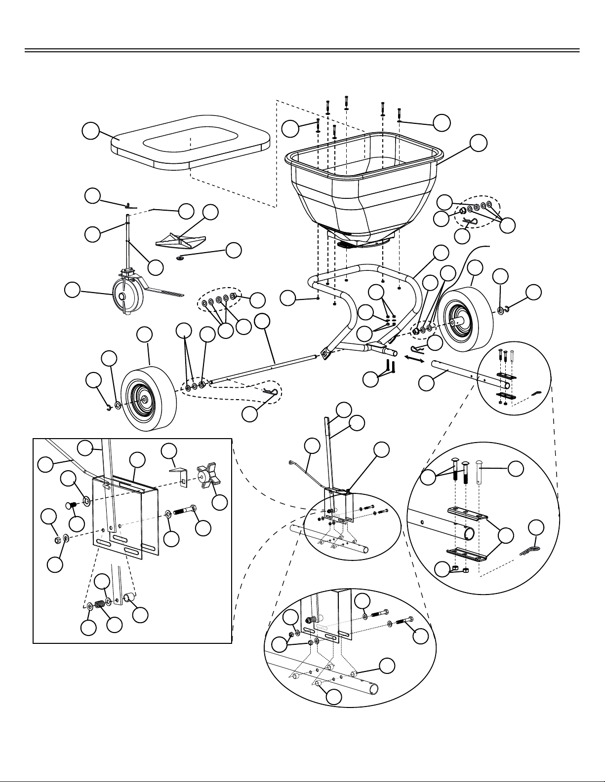
EXPLODED VIEW
Tools Required for Assembly:
• 1/2” Wrench (2)
• 7/16” Wrench (2)
• Pliers
• Flat Head Screwdrivers
2
3
4
1
5
6
7
10
11
12
8
8
10
8
7
9
9
8
11
12
13
14
15
16
17
18
19
20
21
22
24
25
23
26
15
27
30
29
34
33
32
15
28
32
33
32
36
31
37
31
35
36
32
32
15
38
38
40
41
39
FOR METAL
WHEELS
FOR METAL
WHEELS
FOR COMPOSITE (PLASTIC)
WHEELS ASSEMBLY
FOR COMPOSITE (PLASTIC)
WHEELS ASSEMBLY
6
8
42
7
ASSEMBLY
ASSEMBLY
8
42
7
22
43
PARTS REFERENCE
4.
L-1884-C
Page 5

PARTS LIST
PARTS REFERENCE
REF
NO.
1.
2.
3.
4.
5.
6.
7.
8.
9.
10.
11.
12.
13.
14.
15.
16.
17.
18.
19.
20.
21.
22.
23.
24.
25.
26.
27.
28.
29.
30.
31.
32.
33.
34.
35.
36.
37.
38.
39.
40.
41.
42.
43.
* See Hopper Assembly parts list.
PART NO. BS-
26BH
F-1290-10 F-1029-10 Hopper Support 1
F-1030 F-1031 Hopper 1*
F-575 F-575 Washer , Thrust, 1/4” 6
2M0828SS 2M0828SS Bolt, Hex Stainless 1/4” x 1-3/4” 6
B-4785 B-4785 Nylon Lock Nut 1/4” 6
F-1013-01 F-1013-01 Axle, Plated
F-283 F-283 Bearing, Axle
45M2121P 45M2121P Washer , Flat 5/8”
F-705
1008774
F-577 F-577 ‘E’ Ring, Snap, 5/8”
F-1009-10 F-1009-10 Plate, Gauge
F-1010 F-1010-01 Rod, Link
B-3861 B-3861 Pin, Hitch 1/2” x 2-1/2”
10M1032P 10M1032P Bolt, Carriage 5/16” x 2"
B-4786 B-4786 Nylon Lock Nut 5/16”
D-146P D-146P Hairpin Cotter 1/8”
R-892-10 R-892-10 Clevis
50M0416P 50M0416P Pin, Cotter 1/8” x 1"
F-436 F-436 Spring, Agitator , SS
F-365 F-365 O-Ring, 3/8” I.D. AS-110
F-1015 F-1015 Transmission Assembly
F-620 F-620 Hairpin Cotter, Special
F-892 F-892 Pin, Spring
F-591 F-591 Driver, Fan
F-573 F-573 Fan
30M1000P 30M1000P Nut, Hex 5/16”-18
2M1036P-FT 2M1036P-FT Bolt, Hex 5/16” x 2-1/4”
F-1023-10 F-1023-10 Tube, Tow
F-782 F-782 Knob, 4 Prong, Black
F-781-01 F-781-01 Handle, Stop
F-1008-10 F-1008-10 Handle, Flow Control
45M1111P 45M1111P Washer, Flat 5/16”
R-618 R-618 Washer , S pec ial
B-3805 B-3805 Spring
B-3721 B-3721 Spacer , Latch
2M1044P 2M1044P Bolt, Hex 5/16” x 2-3/4”
R-1882 R-1882 Grip, Flat
F-1045 F-1045 Bushing, Pivot
F-787 F-787 Washer , Crvd. Spring-Glv
B-1002P B-1002P Hairpin, Cotter,.148 Dia
11M1012P 11M1012P Bolt, Carriage 5/16” x 3/4”
1008378-01 1008378-01 Spacer
1009191 1009191 Hopper Cover (If equipped)
F-705
1008774
PART NO. BS-
36BH
DESCRIPTION
Wheel, Pneumatic, Metal Rim
Wheel, Pneumatic, Composite (Plastic) Rim
QTY.
1
2
8
2
2
2
1
1
1
2
7
1
2
1
1
1
1
1
1
1
1
2
2
1
1
1
1
8
2
1
1
3
1
4
1
1
1
2
1
INSTALLATION
QUESTIONS?
MISSING PARTS?
REPLACEMENT PARTS?
DON’T GO BACK
TO THE STORE!
STOP
Please call our Customer Service
Department Toll-Free at
877.728.8224
or email
customerservice
@brinly.com
To Order Parts Call:
877-728-8224
Visit us on the web:
www.brinly.com
L-1884-C 5.
Page 6
45
44
46
47
48
49
50
50
51
52
53
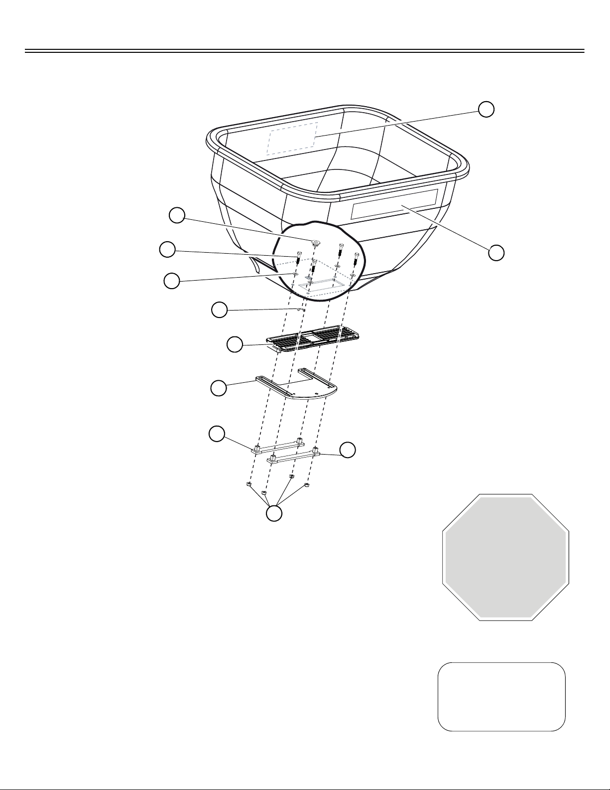
HOPPER EXPLODED VIEW
PARTS REFERENCE
STOP
INSTALLATION
QUESTIONS?
MISSING PARTS?
REPLACEMENT PARTS?
DON’T GO BACK
TO THE STORE!
Please call our Customer Service
Department Toll-Free at
877.728.8224
or email
customerservice
@brinly.com
HOPPER PARTS LIST
REF
NO.
44.
45.
46.
47.
48.
49.
50.
51.
52.
53.
P ART N O.
BS-26BH
F-574 F-574 Bearing, Shaft 1
2M0820SS 2M0820SS Bolt, Hex 1/4”x1-1/4” SS 4
45M0909SS 45M0909SS Washer, Plain SS 4
F-577 F-577 E-Ring, 5/8” 1
B-7392 B-7392 Plate, Directional Control
B-7391 B-7391 Gate
B-7393 B-7393 Strap
F-1026 F-1026 Nut, Hex Lock, 1/4”-20 SS
F-1003 F-1003 Label, Calibration/Directional
B-5924 B-5924 Decal, Logo
6.
L-1884-C
P ART N O.
BS-36BH
DESCRIPTION
QTY.
1
1
2
4
1
1
To Order Parts Call:
877-728-8224
Visit us on the web:
www.brinly.com
Page 7
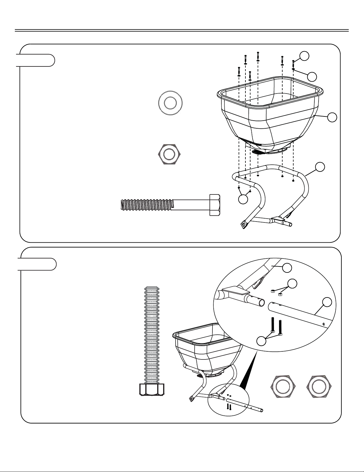
Figure 1.
Figure 2.
INSTALL HOPPER SUPPORT
TO THE HOPPER
3
Flat Washer (Nylon), 1/4”
Qty. 6
4
Bolt Hex, 1/4”x1-3/4”
Qty. 6
5
Lock Nut, Nylon, 1/4””
Qty. 6
1
2
3
4
5
1a. Install six 1/4 x 1-3/4 in. hex bolts (4),
and 1/4 in. thrust washer (3) through
top of hopper (2) and through support
frame (1), as shown.
1b. Secure bottom of bolt with 1/4 in. lock-
nut (5). T o avoid damage to plastic, do
not overtighten hardware.
27
Bolt Hex, 5/16”x2-1/4”
Qty. 2
26
Hex Nut 5/16”
Qty. 2
27
2a. Attach Tow Tube (28) to the Hopper
Support (1)1b. Secure using two
5/16”x2-3/4” Hex Bolts (27) and two
5/16”-18 Hex Nuts (26).
1
28
26
ATTACH TOW TUBE
ASSEMBLY
L-1884-C 7.
Page 8

Figure 3.
ASSEMBLY FAN TO TRANSMISSION
24
Fan Driver
Qty. 1
3a. Slide the Fan Driver (24) and Fan (25)
on to the shaft of the Transmission
Assembly (21) until both reach the Pin
Spring (23)
Note: This is for pre-assembly only. Final
adjustment of the fan is made later.
24
23
25
21
ASSEMBLY
8.
L-1884-C
Page 9
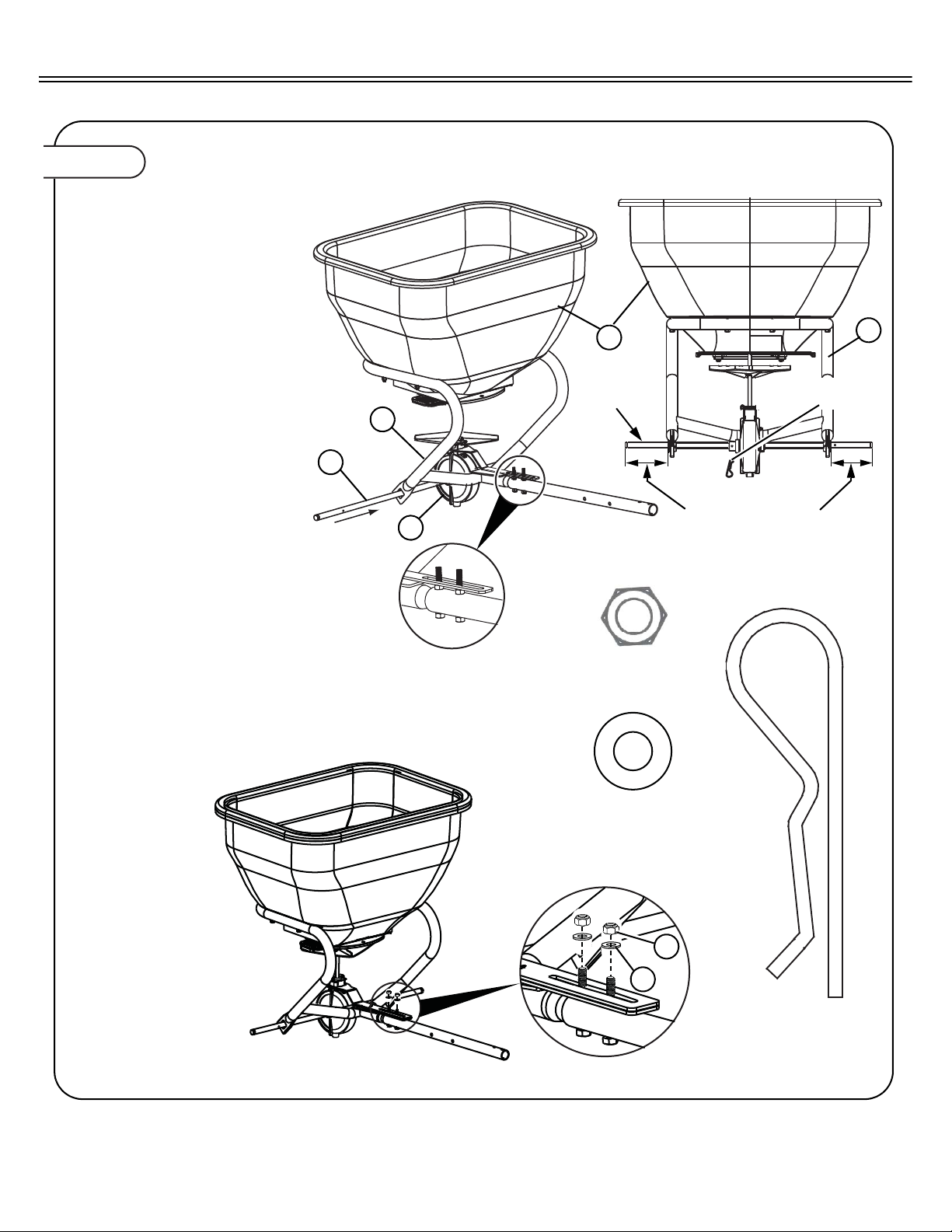
Figure 4.
INSTALL TRANSMISSION & AXLE
4a. Maneuver the transmission
assembly (21) shaft into the
center hole of the Hopper
Assembly (2). Ensure that the
slot of the transmission brace
rests on top of the two tow tube
hex nuts previously installed in
Figure 2, as shown.
Note: Failure to install the transmis-
sion bracket correctly may
void the warranty .
4b. Insert Axle (6) through both
Hopper Support (1) square
openings and through center of
transmission assembly (21), as
shown.
Note: The axle needs to be installed
as shown in order to engage
the transmission assembly .
4c. Rotate the axle to line up the
hole with the hole in Transmission assembly hub and insert
Hairpin Cotter (40)
4d. Secure the transmission brace
by attaching two 5/16” Flat
Washers (32) and two Nylon
Lock Nuts (15), then tighten.
2
21
6
Axle only
goes on
one way
A
A
Install Axle - “A” is
equal lengths on
both sides.
1
1
BACK
Insert Hairpin Cotter
(40)
32
Flat Washer 5/16”
Qty. 2
40
Hairpin Cotter
Qty. 1
15
Lock Nut, Nylon 5/16”
Qty. 2
32
15
ASSEMBLY
L-1884-C 9.
Page 10
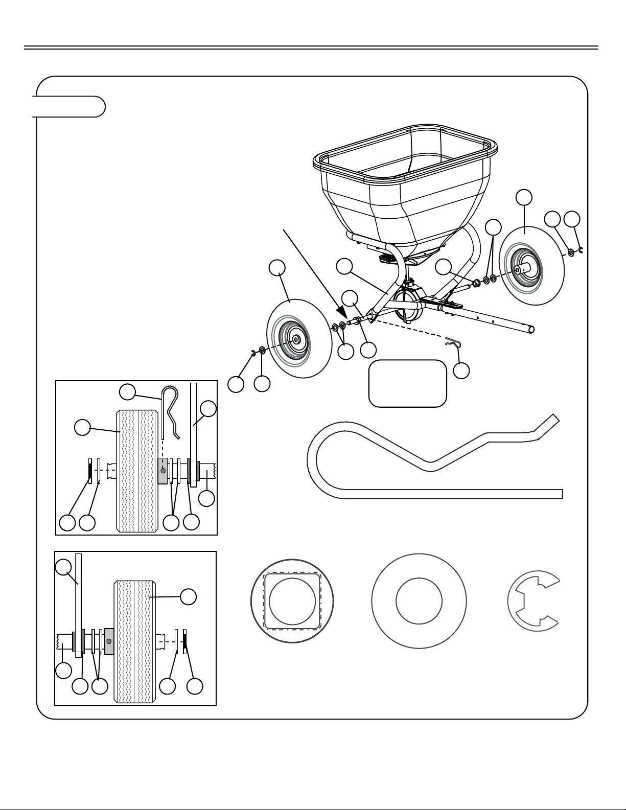
Figure 5-1.
INSTALL WHEELS (METAL)
Note: The unit will be shiped with one of two
types of wheels. Determine whether the
wheels have metal or composite (plastic)
rims. If the rim is metal, proceed to step
5a. If the rim is plastic, proceed to step
5c.
5a. Attach each Wheel (9) to the Axle (6)
using hardware in the following order:
• One Axle Bearing (7)
• One or two Flat Washer 5/8” (8) - use
one or two as needed.
• One Metal-Rimmed Wheel (9)
• One Flat Washer 5/8” (8)
• One Snapping E-Ring (10)
5b
. Secure Axle to the right wheel by insert-
ing Hairpin Cotter (22) through the wheel
hub and axle. Proceed to step 6a.
Note: The axle may need to be turned in order
to line up the hole in the axle with the
hole through the wheel hub.
8
Flat Washer 5/8”
Qty. 6
10
Snap Ring E-Type
Qty. 2
15
Axle Bearing
Qty. 2
22
22
Hairpin Cotter
Qty. 1
10 8 8
7
1
22
7 8 8 10
1
9
9
10
9
9
1
6
6
8
7
8
8 10
8
6
RIGHT
WHEEL
LEFT
WHEEL
RIGHT
WHEEL
LEFT
WHEEL
Apply grease to axle
and wheel bearings
Add or delete Flat
Washer (8) to
reduce Axle side to
side movement.
7
ASSEMBLY
10.
L-1884-C
Page 11
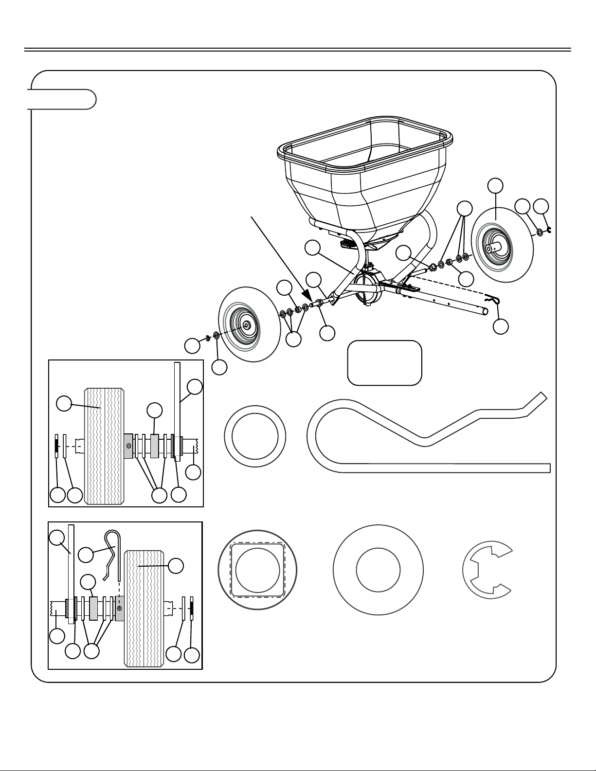
Figure 5-2.
INSTALL COMPOSITE WHEELS (PLASTIC)
5c.Attach each Wheel (9) to the Axle (6)
using hardware in the following
order:
• One Axle Bearing (7)
• One Flat Washer 5/8” (8)
• One Spacer (42)
• One or two Flat Washer 5/8” (8) use 1 or two as needed.
• One Composite Wheel (9)
• One Flat Washer 5/8” (8)
• One Snapping E-Ring (10)
5d. Secure Axle to the left wheel by
inserting Hairpin Cotter (22) through
the wheel hub and axle.
Note: The axle may need to be turned in
order to line up the hole in the axle
with the hole through the wheel
hub.
8
Flat Washer 5/8”
Qty. 6
10
Snap Ring E-Type
Qty. 2
15
Axle Bearing
Qty. 2
22
22
Hairpin Cotter
Qty. 1
10
8
8
7
1
22
7 8
8
10
1
9
9
10
42
9
1
6
6
8
7
8
8 10
8
6
RIGHT WHEEL
LEFT WHEEL
RIGHT
WHEEL
LEFT
WHEEL
Apply grease to axle
and wheel bearings
Add or delete Flat
Washer (8) to
reduce Axle side to
side movement.
42
42
Spacer
Qty. 2
42
42
7
ASSEMBLYASSEMBLY
L-1884-C 11.
Page 12
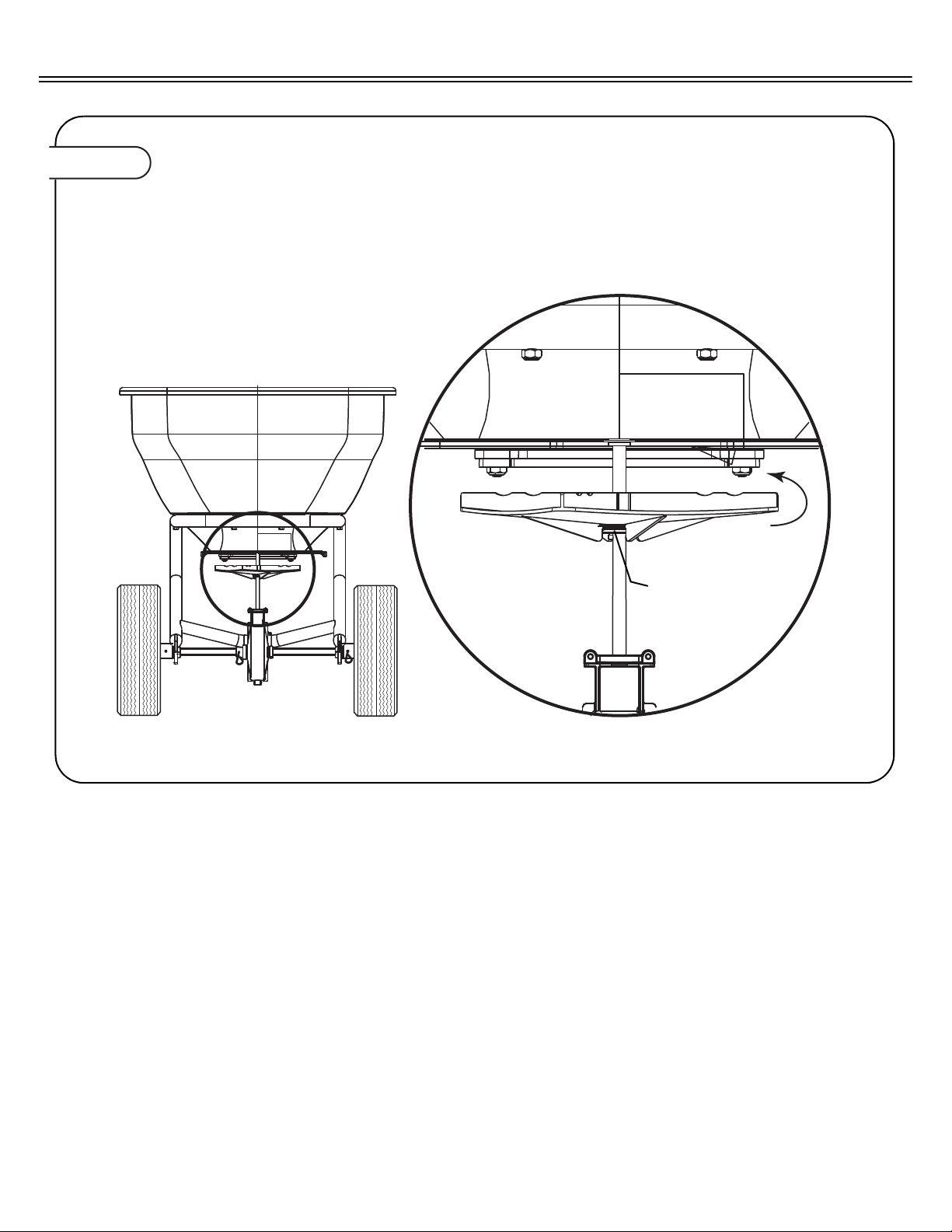
Figure 6.
FAN ADJUSTMENT
6a. Adjust fan upwards on shaft as close as
possible to the bottom of the hopper without touching during operation.
Note: The fan and fan driver normally rests on
the spring pin, but may be adjusted
upward approximately 1/8 of and inch.
If neccesary, adjust
fan upwards on shaft
as close as possible to
the bottom of the hopper without touching
during operation.
ASSEMBLY
12.
L-1884-C
Page 13
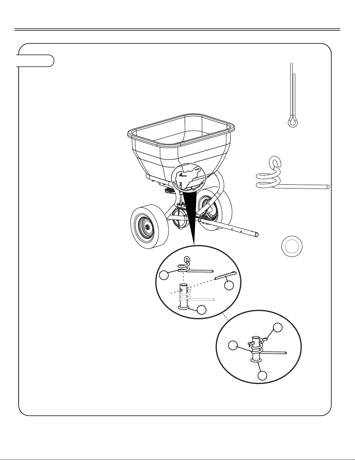
Figure 7.
INSTALL AGITATOR
7a. Place O-Ring (20) over transmission
shaft. Slide down to hopper bottom to create seal.
7b. Slide Agitator Spring (20) over transmis-
sion shaft.
7c. Insert Cotter Pin (18) through hole at top
of transmission shaft. Flair ends to keep
in place, as shown.
18
18
Cotter Pin, 1/8”x1”
Qty. 1
19
Agitator Spring
Qty. 1
20
O-Ring 3/8”
Qty. 1
19
20
18
19
20
ASSEMBLY
L-1884-C 13.
Page 14
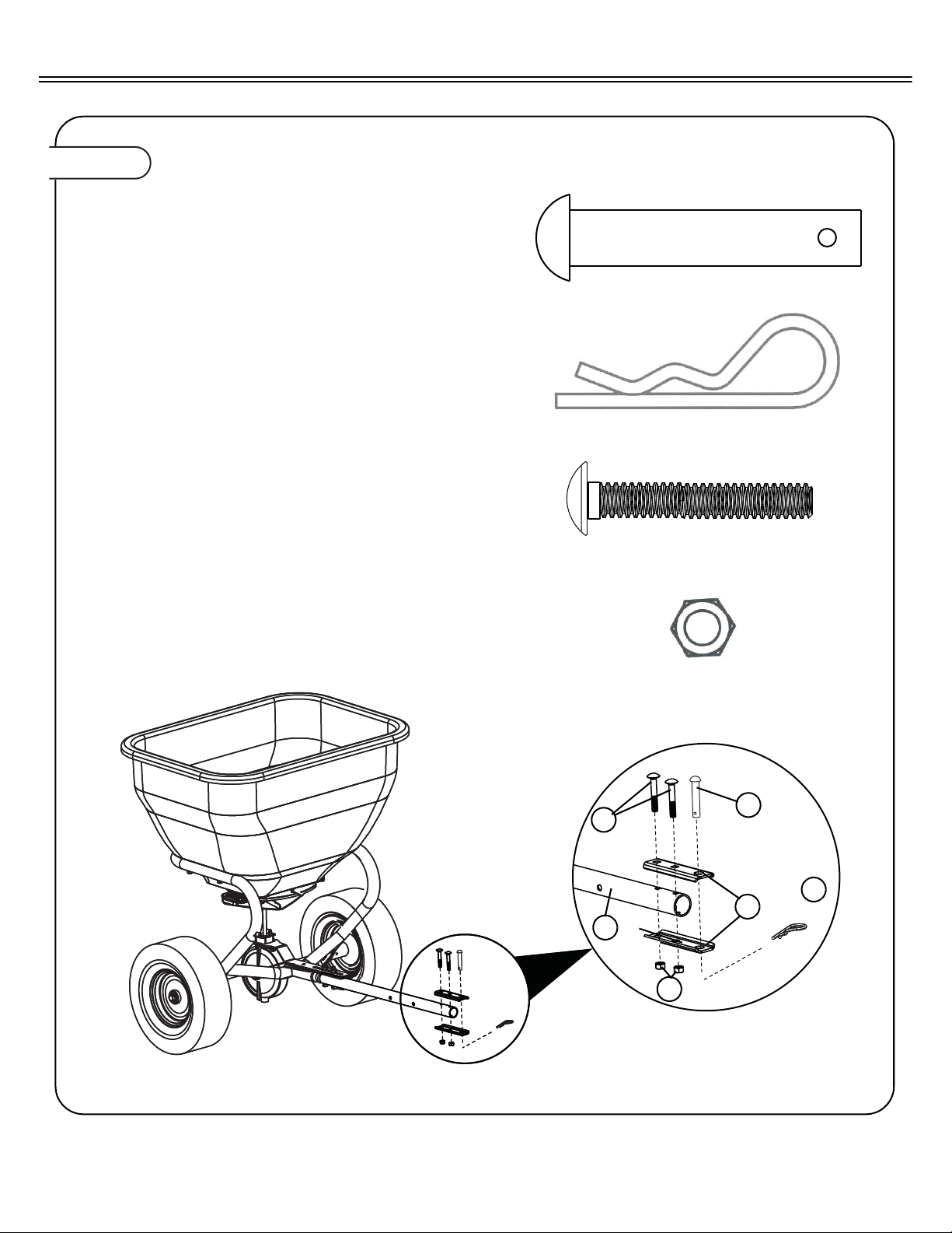
Figure 8.
INSTALL CLEVIS
8a. Attach the upper and lower Clevis (17)
halves to the Tow Tube (28). Secure with
two 5/16”x2” Carriage Bolts (14) and two
5/16” Nylon Hex Nuts (15), as shown.
8b. Insert 1/2”X2-1/2” Hitch Pin in to Clevis
and secure using Hairpin Cotter (16), as
shown.
13
13
Hitch Pin 1/2” x2-1/2”
Qty. 1
28
17
15
16
Hairpin Cotter 1/8”
Qty. 1
14
Carriage Bolt 5/16”x2”
Qty. 2
15
Nylon Lock Nut 5/16”
Qty. 2
14
16
ASSEMBLY
14.
L-1884-C
Page 15

Figure 9.
ASSEMBLE GAGE PLA TE
9a. Insert Stop Handle (31) through slot
opening at the top of the Gauge Plate
(11).
9b. Insert the ‘S’ shaped end of Link Rod
(12) through the upper hole of the
Flow Control Handle (31).
9c. Assemble Flow Control (31) to Gage
Plate (11) as shown, using hardware
provided:
• One 5/16”x2-3/4” Hex Bolt (36)
• Two 5/16” Flat Washers (32)
• One Latch Spacer (35)
• Two Special Washers (33)
• One Spring (34)
• One 5/1/6” Hex Nut (15)
Note: See graphic inset below for hard-
ware orientation.
9d. Attach Handle Stop (30) and Knob
(29) as shown, using hardware provided:
• One 5/16”x3/4” Carriage Bolt (41
• One Crvd Washer. (39).
9e. Slide Flat Grip (37) on end of Flow
control Handle (31).
34
Spring
Qty. 1
11
30
29
31
12
15
32
39
33
34
35
32
36
41
37
12
31
11
12
34
15
3232
3533 35
31
12
36
5/16”x2-1/4” Hex Bolt
Qty. 1
34
Washer Special
Qty. 2
32
Washer 5/16”
Qty. 2
39
Washer Crvd
Qty. 1
35
Spacer, Latch
Qty. 1
29
Knob 4-Prong
Qty. 1
15
Hex Nut 5/16”
Qty. 1
ASSEMBLY
L-1884-C 15.
Page 16
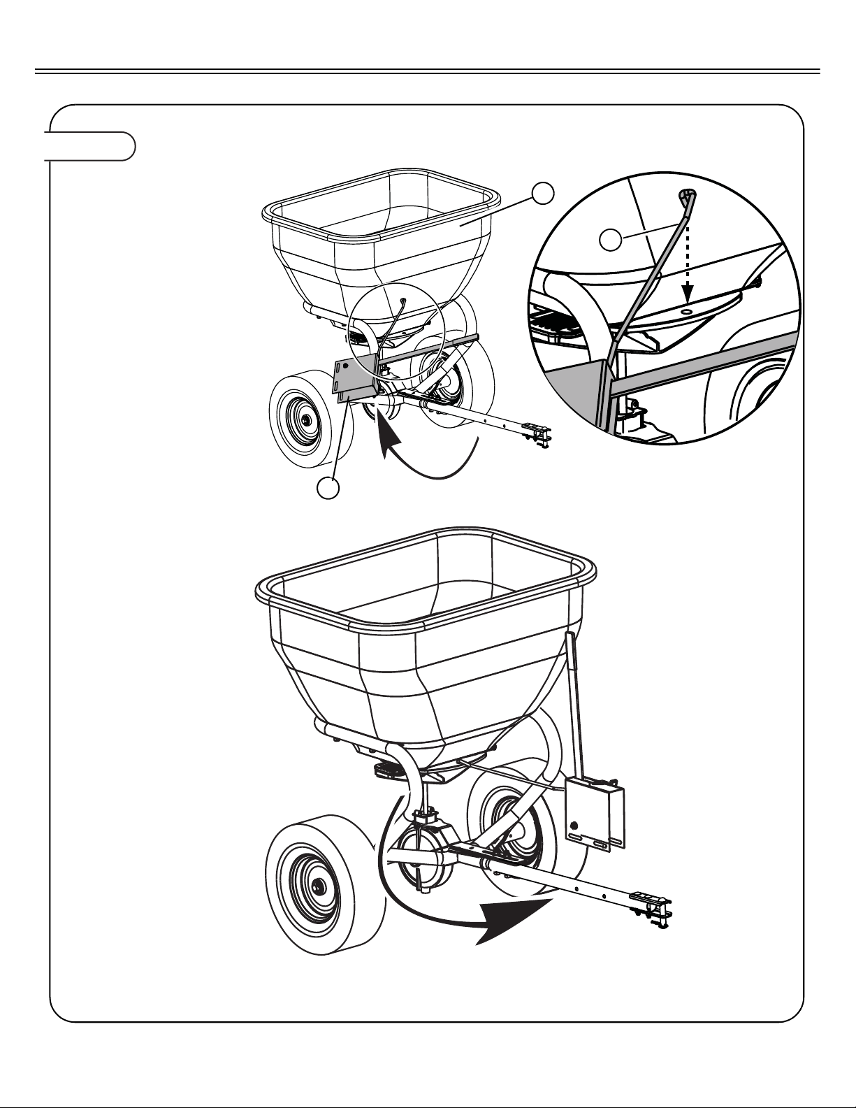
Figure 10a.
ATTACH GAGE PLATE TO SPREADER
10a. Rotate assembled Gage
Plate (1 1) approximately 90 °
clockwise and insert formed
end of the of the Link Rod
(12) in to the hole provide on
the Hopper (10) control
plate, as shown.
10b. Rotate Gage Plate counter-
clockwise until the handle is
oriented upward and the bottom of the Gage Plate is over
the Tow Tube (28).
11
12
10
ASSEMBLY
16.
L-1884-C
Page 17
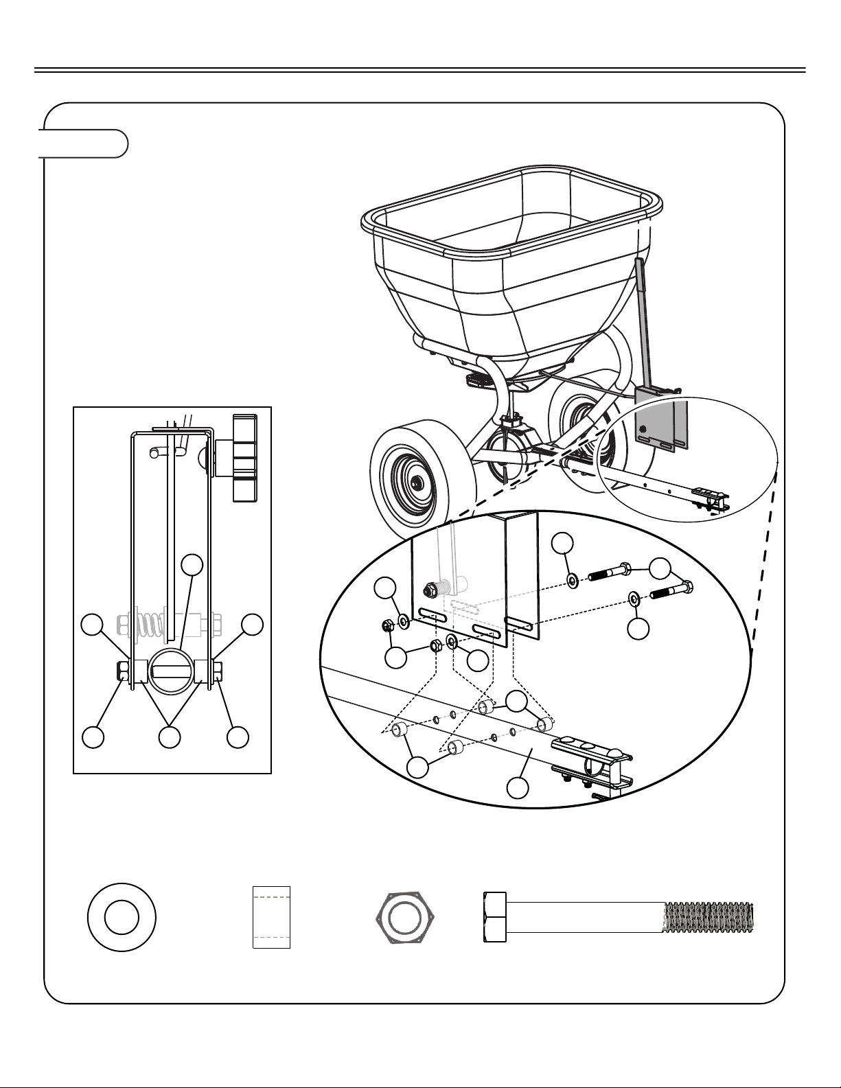
Figure 10b.
ATTACH GAGE PLATE TO SPREADER
10c. Attach the Gage Plate to the Tow
Tube (28) as shown, using hardware provided: Do tighten the hex
nuts until after calibrating the gage
plate.
• Two 5/16”x2-3/4” Hex Bolt (36)
• four 5/16” Flat Washers (32).
• Four Pivot Bushings (38).
• Two 5/1/6” Hex Nuts (15).
Note: See graphic inset below for hard-
ware orientation.
38
Bushing, Pivot
Qty. 4
36
5/16”x2-1/4” Hex Bolt
Qty. 2
32
Washer, 5/16”
Qty. 4
32
38
15
Hex Nut 5/16”
Qty. 2
32
32
36
38
15
32
28
15
32
38 36
32
28
ASSEMBLY
L-1884-C 17.
Page 18
29
28
31
12
11
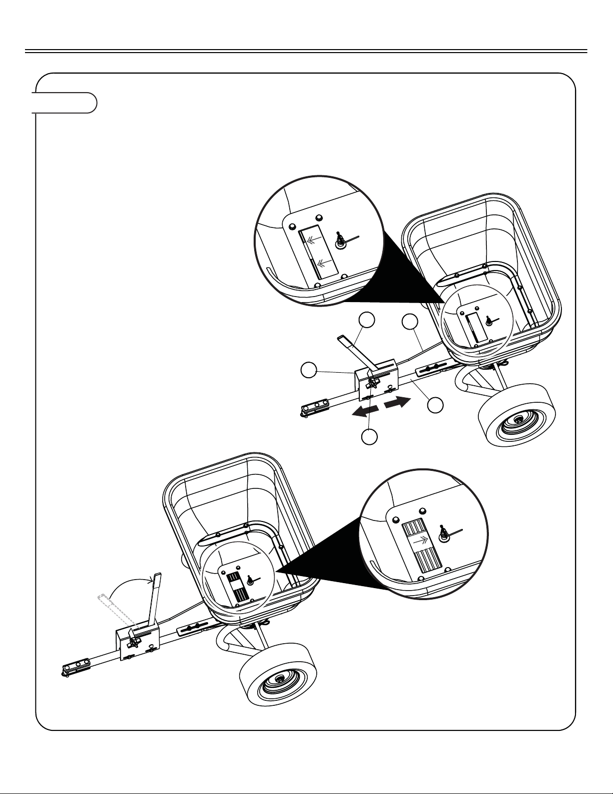
Figure 11.
CALIBRATE GAGE PLATE
11a. Loosen the knob (29) and move to the
#10,OPEN position, retighten.
11b. Move Flow Control Handle (31) to the
#10, OPEN position.
11c. Ensure that hopper control gate (48)
opens fully, if not slide the gage plate
(11) forward or backward until control
gate is fully open
1 1d.Tighten gage plate securely to theT ow
Tube (28) by tightening the hardware
installed in Step 10c.
11e. Move Flow Control Handle to the
CLOSE position, verify hopper control
gate fully closes.
11f Tighten Flow Control Handle securely
to the gage plate by tightening hardware assembled in Step 9c.
Your broadcast spreader is now ready for
operation.
CALIBRATION
18.
L-1884-C
Page 19
SPREAD PATTERN CONTROL
• CENTER MATERIAL SPREAD PATTERN BEHIND TRACTOR
• MOVE HOLE LEFT OR RIGHT TO CENTER MATERIAL DISTRIBUTION
SPREAD PATTERN CONTROL
• CENTER MATERIAL SPREAD PATTERN BEHIND TRACTOR
• MOVE HOLE LEFT OR RIGHT TO CENTER MATERIAL DISTRIBUTION
SPREAD PATTERN CONTROL
• CENTER MATERIAL SPREAD PATTERN BEHIND TRACTOR
• MOVE HOLE LEFT OR RIGHT TO CENTER MATERIAL DISTRIBUTION
DIRECTIONAL CONTROL ILLUSTRATION
Lawn
Directional Control Label
Directional Control Plate (centered)
SPREAD PATTERN CONTROL
• CENTER MATERIAL SPREAD PATTERN BEHIND TRACTOR
• MOVE HOLE LEFT OR RIGHT TO CENTER MATERIAL DISTRIBUTION
SPREAD PATTERN CONTROL
• CENTER MATERIAL SPREAD PATTERN BEHIND TRACTOR
• MOVE HOLE LEFT OR RIGHT TO CENTER MATERIAL DISTRIBUTION
SPREAD PATTERN CONTROL
• CENTER MATERIAL SPREAD PATTERN BEHIND TRACTOR
• MOVE HOLE LEFT OR RIGHT TO CENTER MATERIAL DISTRIBUTION
Directional Control Label
Directional Control Plate (position)
Sidewalk
Planting Bed
Right
DIRECTIONAL CONTROL ILLUSTRATION
OPERATION
Operation
The Fan speed and the spread width are controlled by the
speed of the vehicle. The recommended operating speed is
slightly faster than that of a brisk walk, approximately 3 MPH
(equal to the vehicle traveling 40 ft. in 9 seconds).
The Gage Plate Assembly operates the Flow Control Gate. The
Gage Plate is marked from 0 (closed) to 10(fully open). The
position selected determines the amount of material to be
broadcast. The higher the number, the heavier the application
of material. Flow Control settings for many of the common fertilizers, insecticides, and grass seeds are provided in Table 1.
If the material is not listed in Table 1, then use the calibration
table found on the decal provided on the hopper.
After determining the correct setting number for your material,
move the Flow Control Handle to that position. Lock the handle
in place by moving the Handle Stop to that position and tighten
knob.
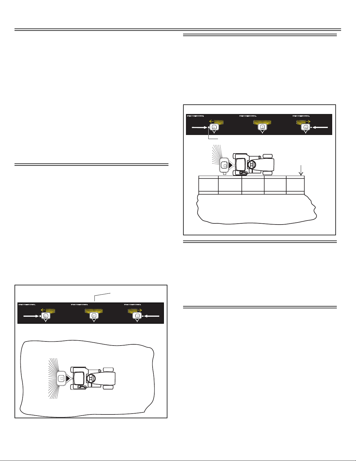
DIRECTIONAL CONTROL - NORMAL OPERATION
Fertilizers, Insecticides, and Grass Seed each have different
particle size and weight. This can be referred to as particle density. As the particles are impacted by the fan, the distribution
can be centered or slightly off center depending on particle
density and forward vehicle speed.
DIRECTIONAL CONTROL - ONE SIDE ONLY SPREADING
The directional control plate can be used for adjusting the
material spread pattern when spreading near sidewalks, planting beds, etc. Slide the directional control plate to the desired
position to control material flow for the spreader. The hopper
decal illustrates the direction control coverage. The directional
control plate only operates with 90% shut-off of material to the
right side or left side of the vehicle as shown in the illustration
below.
Adjustment can be made by moving the Direction Control Handle to the RIGHT or LEFT. The directional decal located below
the Directional Control Plate handle will aid you in adjusting the
spread pattern. For most applications the handle should be
placed close to the center position described by the label
below. If the material is coming out right or left during operation,
adjustment of this lever should be made to center the material
distribution pattern behind the vehicle. Y our broadcast spreader
has a patented feature to allow you to adjust for centering.
OPERATING TIPS
Do not load the hopper with more than the maximum weight
capacity of 175 pounds
Break up any lumps as you fill the Hopper.
Do not use on windy days, especially when spreading fine
grass seed or herbicides.
MAINTENANCE
The key to years of trouble-free service is to keep your
Spreader clean and dry.
• Never allow material to remain in Hopper for extended
periods of time.
• Should rust develop, sand lightly and then paint area with
enamel.
• Periodically check all fasteners for tightness.
• Rinse/dry inside and outside of spreader after each use.
Move Flow Control as you rinse to avoid build up of material.
L-1884-C 19.
Page 20
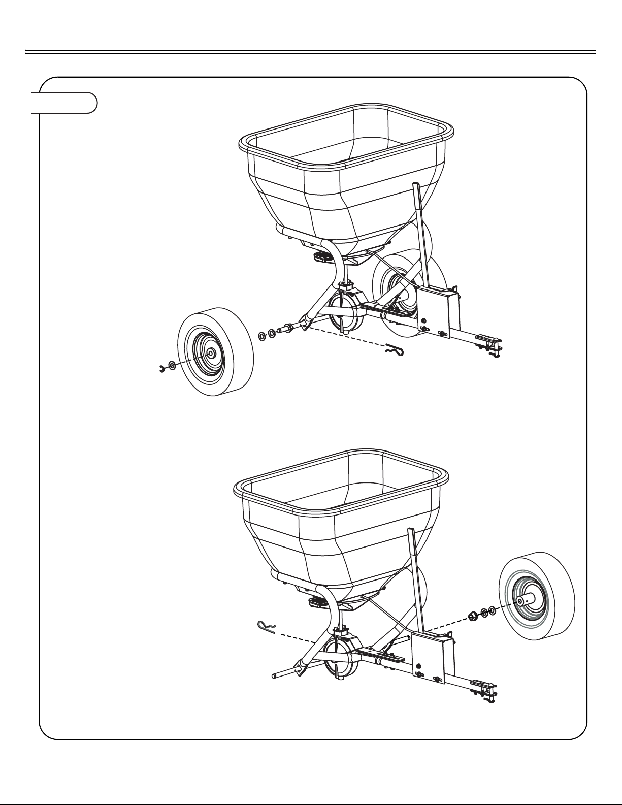
Figure 12.
1. Remove Wheels
2. Clean Parts
3. Lubricate bearings and axle lightly.
4. Remove cotter from transmission
housing
5. Remove axle
ANNUAL MAINTENANCE
20.
L-1884-C
Page 21
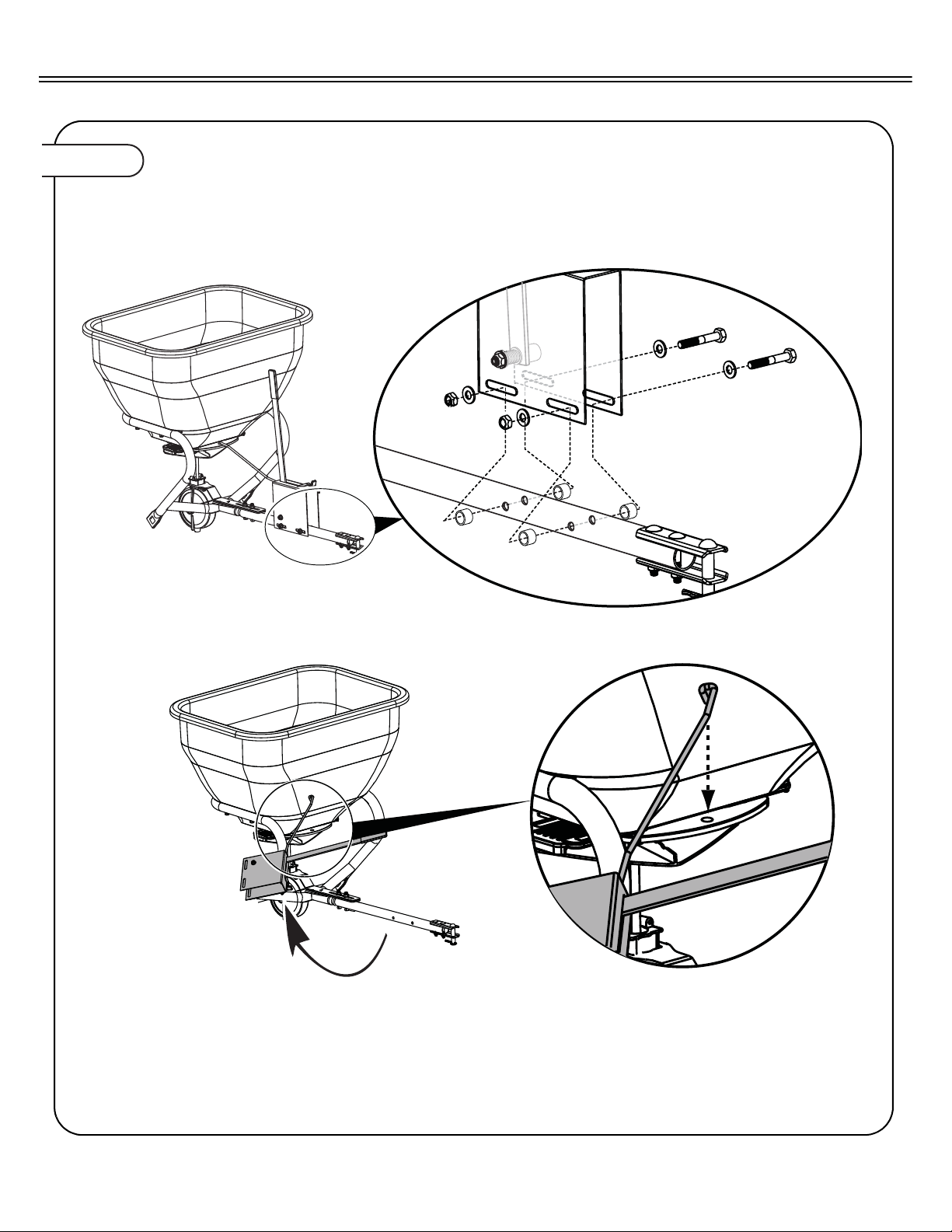
Figure 13.
6. Remove Gage Plate.
ANNUAL MAINTENANCE
L-1884-C 21.
Page 22
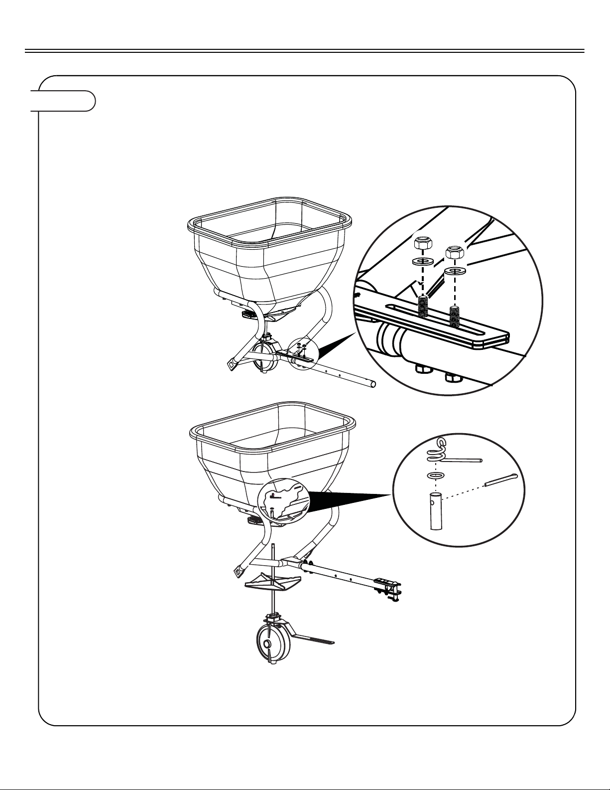
Figure 14.
7. Remove transmission bracket.
8. Remove Transmission.
8. Clean Fan
ANNUAL MAINTENANCE
22.
L-1884-C
Page 23
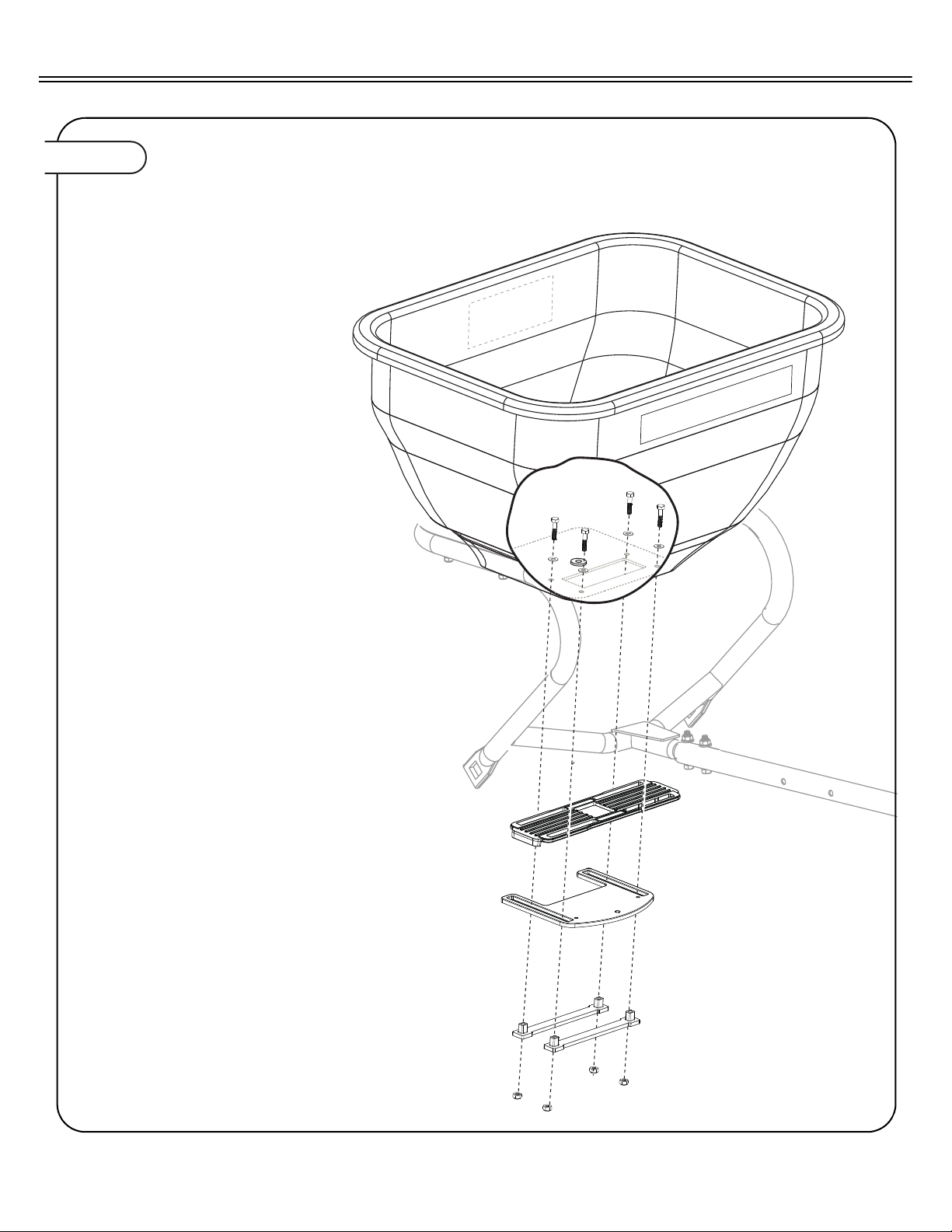
Figure 15.
10. Remove the 4 bolts that hold the
Gate and Directional Control Plate.
11. Separate parts, as shown.
12. Clean parts thoroughly with soap
and water.
ANNUAL MAINTENANCE
L-1884-C 23.
Page 24
MEDIA FLOW SETTINGS
FLOW SETTINGS
The Table 1 is a list of flow control settings for specific products available for use with the spreader.
CAUTION:
dangerous. Avoid injury to operator or
bystanders:
• Read chemical container label for mixing
and handling instructions. A Material Safety
Data Sheet (MSDS) should be supplied by the
chemical dealer and provides proper safety
information.
• Wear proper clothing and safety equipment
while handling or applying spray chemicals.
• Wear a full covering of clothing, protective
goggles and rubber gloves.
• Prohibit all smoking, drinking, and eating
around chemicals.
• When filling tank, never allow end of water
hose to contact
Avoid injury! Chemicals can be
Table 1: Flow Control Settings for Specific Fe rtilize r's, In se ctic ide s, Gras s S ee ds
lbs/1000
sq. ft.
Flow Control
Setting
Some products may not be available in all areas.
Flow control settings are based on 3 mph forward speed.
Media
10 3 All American All Purpose Fertilizer 10-10-10.
3.8 2.5 Bayer Season Long Grub Control
2.9 2 Bayer Season Long Grub Control
3 2 Bayer Complete Insect Killer
2 1.5 Bayer Complete Insect Killer
3 1.5 Bayer Power Force Multi-Insect Killer
2 1 Bayer Power Force Multi-Insect Killer
3 1.5 Bayer Grub Control
2 1.5 Bayer Grub Control
3.2 2 Bayer Lawn Fertilizer Plus Weed Control II 30-3-4
3.8 2 Bayer Season Long Grub Control
2.9 1.5 Bayer Season Long Grub Control
3.6 2 Bayer Lawn Starter Fertilizer 20-27-5
3.2 2 Bayer Lawn Fertilizer Plus Crabgrass Preventer 30-3-4
3 2 Eliminator Ant, Flea, and Tick Killer Granules
2.5 1.5 Eliminator Ant, Flea, and Tick Killer Granules
2 1.5 Eliminator Ant, Flea, and Tick Killer Granules
2 2 Eliminator 5% Diazinon Insect Killer Granules
7 2.5 Howard Johnsons All-purpose Fertilizer 8-8-8
7 2.5 Howard Johnsons All-purpose Fertilizer 10-10-10
7 2.5 Howard Johnsons All-purpose Fertilizer 12-12-125 2 Ironite 1-0-0
4 2 Klay Soft Pelletized Gypsum Soil Conditioner
3 1.5 Klay Soft Pelletized Gypsum Soil Conditioner
2 1.5 Klay Soft Pelletized Gypsum Soil Conditioner
24.
L-1884-C
Page 25

MEDIA FLOW SETTINGS
Table 1: Flow Control Settings for S pecific Fertilizer's, Insecticid es, Grass Seeds (Cont’d)
lbs/1000
sq. ft.
4 2 Lesco Pre-M.86% Plus Fertilizer 25-0-7
4.2 2 Lesco Starter Fertilizer 18-24-12
4.2 2 Lesco Turf Fertilizer 24-2-11
4 2 Lesco Weed and Feed
8 3.5 Master Turf Ultimate Tall Fescue Blend
4 2.5 Master Turf Ultimate Tall Fescue Blend
8 3.5 Milogranite 6-2-0
16 5 Milogranite 6-2-0
3.2 2 Miracle-Gro Lawn Fertilizer plus Weed Control 28-3-3
3.6 2 Miracle-Gro Starter Lawn Fertilizer 20-27-5
3.1 1.5 Miracle-Gro Starter Lawn Fertilizer 29-3-4
9.6 3 Ortho Lawn Insect Killer Granules
4.8 2 Ortho Lawn Insect Killer Granules
2.4 1 Ortho Lawn Insect Killer Granules
1.2 1 Ortho Lawn Insect Killer Granules
4 2 Ortho Max Insect Killer for Lawns
2 1.5 Ortho Max Insect Killer for Lawns
1 1 Ortho Max Insect Killer for Lawns
10 3 Parkers Super Soilife Lawn & Garden Fertilizer 10-10-10
6.5 2 Parkers Super Soilife Lawn & Garden Fertilizer 16-4-8
3.6 2 Pennington Lawn Starter Fertilizer 18-24-6
10 4 Pennnigton Master Turf High Traffic Lawn Seed Mixture
5 3 Pennnigton Master Turf High Traffic Lawn Seed Mixture
8 4 Pennington Master Turf Shady Lawn Seed Mixture
4 3 Pennington Master Turf Shady Lawn Seed Mixture
10 4 Pennington Master Turf Sun & Shade Lawn Seed Mixture
5 3 Pennington Master Turf Sun & Shade Lawn Seed Mixture
2 1.5 Real-Kill Multi-Purpose Lawn and Garden Insect Killer
2.5 1.5 Real-Kill Multi-Purpose Lawn and Garden Insect Killer
10 4 Rebels Supreme Blend Grass Seed for Sun & Shade
5 3 Rebels Supreme Blend Grass Seed for Sun & Shade
10 4 Ringer Lawn Restore 10-2-6
12.3 4.5 Sam's Choice Crabgrass Preventer 30-3-4
8.1 3 Sam's Choice Crabgrass Preventer 30-3-4
6 3 Sam's Choice Crabgrass Preventer 30-3-4
5.4 2.5 Sam's Choice Crabgrass Preventer 30-3-4
3 1.5 Sam's Choice Insect Control Plus Fertilizer 28-4-6
3.2 2 Sam's Choice Lawn Food 29-3-4
6 3 Sam's Choice Starter Fertilizer 20-27-5
3.6 2 Sam's Choice Starter Fertilizer 20-27-5
4 3 Scotts Classic Grass Seed Fall Grass Seed Mix
2 2 Scotts Classic Grass Seed Fall Grass Seed Mix
2.3 1.5 Scotts Grubex
Flow Control
Setting
Media
L-1884-C 25.
Page 26

MEDIA FLOW SETTINGS
Table 1: Flow Control Settings for S pecific Fertilizer's, Insecticid es, Grass Seeds (Cont’d)
lbs/1000
sq. ft.
3.1 2 Scotts Grubex Season Long Grub Control
2.3 2 Scotts Grubex Season Long Grub Control
1.4 1.5 Scotts Lawn Fungus Control
2.7 2 Scotts Lawn Fungus Control
2.2 2 Scotts Pure Premium Kentucky Bluegrass Mix
1.1 1.5 Scotts Pure Premium Kentucky Bluegrass Mix
2.5 2 Scotts Pure Premium Sun & Shade Grass Seed Mixture
1.25 1.5 Scotts Pure Premium Sun & Shade Grass Seed Mixture
3.6 2 Scotts Starter Fertilizer 20-27-5
5.9 2 Scotts Starter Fertilizer 20-27-5
2.7 2 Scotts Turf Builder 28-3-8
3.1 1.5 Scotts Turf Builder Lawn Fertilizer 29-3-4
2.7 2 Scotts Turf Builder with Summer Guard
2.9 2 Scotts Turf Builder Plus Weed Control
3.3 1 Scotts Winterizer 22-4-1
4.6 2 Sevin Lawn Insect Granules
2.33 2 Sevin Lawn Insect Granules
2.25 2 Sevin Lawn Insect Granules
3 2 Spectracide Grub Stop
3 1 Spectracide Triazicide Insect Killer Granules
3.6 2 Sta-Green Lawn Fertilizer 29-2-5
2 1.5 Sta-Green Lawn Weed Control
3.2 2 Sta-Green 200 Plus Weed & Feed 28-3-3
3.6 2 Sta-Green Starter Fertilizer 18-24-10
3.2 2 Sta-Green Weed & Feed 28-2-4
10 4 Sun & Shade Grass Seed Mixture
5 3 Sun & Shade Grass Seed Mixture
3 1 Vigoro Insect Control Plus Fertilizer
3.6 2 Vigoro Starter Fertilizer
3.2 2 Vigoro Turf Fertilizer 29-3-4
3 1.5 Vigoro Ultra Truf Winterizer 22-3-14
3.2 2 Vigoro Weed and Feed
4 3 Wal Mart Gardens Kentucky Bluegrass Grass Seed
2 2 Wal Mart Gardens Kentucky Bluegrass Grass Seed
8 4 Wal Mart Gardens Kentucky 31 Tall Fescue
4 3 Wal Mart Gardens Kentucky 31 Tall Fescue
3.2 2 Wal Mart Weed & Feed 28-3-3
Flow Control
Setting
Media
Note: If the product you are using is not listed in the flow control set-
ting table, use the this calibration guide located on the hopper
decal of the spreader to set the flow control.
Using application information on product package, find the calibration setting on the hopper decal and set flow control lever.
26.
L-1884-C
Page 27

TROUBLESHOOTING
Table 2: Troubleshooting - S preading Difficulties & Remedies
PROBLEM CAUSE/CONDTION REMEDY
Too much/not enough
material dispensed.
Flow Control Handle
hard to operate or
won’t move
Fan does not turn
when towing
spreader.
Gage Plate not calibrated Insure Gage Plate is properly calibrated, (Refer to Figure 11).
Gate(47) and directional control plate(46) clogged with
material.
Drive hairpin cotter (22) not
properly inserted through
Wheel hub (9) hub and axle
(6.)
Transmission cotter pin (40)
missing or not properly
inserted through transmission
hub (21) hub and axle (6)
Fan (25) hits bottom of hopper
gate (47) and directional control plate (46).
Fan (25) slips on transmission
shaft (21).
Remove and clean the Gate and Directional Control Plate with
soap and water, (Refer to Figure 12 through Figure 15).
Install or replace missing hairpin cotter, (Refer to Figure 5)
Install or replace missing cotter pin through transmission hub
(21) hub and axle (6), (Refer to Figure 4).
Adjust fan to clear hopper gate and directional control plate,
(Refer to Figure 6).
Install Fan Driver (24) so that the four fan gussets on the bottom of the fan compresses the fan driver.
Transmission malfunction
SPECIFICATIONS
Dimensions
Size (maximum tow weight) ..................................79 kg (175 lbs).
Capacity ........................................... ..............0.10 cu m (3.5 cu ft).
Tires
Size ......................................................................................13 x 5
Inflation Pressure .................................................................20 psi
With the broadcast spreader attached to your machine lift the
drive wheel and rotate. At the same time apply gentle pressure
to the fan shaft. It should turn with each rotation of the wheel.
GETTING QUALITY SERVICE
Quality Continues with Quality Service
We provide a process to handle your questions or problems.
Follow the steps below to get answers to any questions you may have
about your product.
1. Refer to your attachment and machine operator manuals.
2. In North America or Canada, call 1-877 728-8224 and provide
product serial number (if available) and model number.
L-1884-C 27.
Page 28

MANUFACTURER’S LI MITED WARRANTY
FOR
Pull Behind Accessories
The limited warranty set forth below is given by Brinly-Hardy
Company with respect to new merchandise purchased and
used in the United States, its possessions and territories.
Brinly-Hardy Company warrants the products listed below
against defects in material and workmanship, and will at its
option, repair or replace, free of charge, any part found to be
defective in materials or workmanship. This limited warranty
shall only apply if this product has been assembled, operated,
and maintained in accordance with the Operator’s manual furnished with the product, and has not been subject to misuse,
abuse, commercial use, neglect, accident, improper maintenance, alteration, vandalism, theft, fire, water, or damage
because of other peril or natural disaster.
Normal Wear Parts or components thereof are subject to separate terms as follows: All normal wear parts or component failures will be covered on the product for a period of 90 days.
Parts found to be defective within the warranty period will be
replaced at our expense. Our obligation under this warranty is
expressly limited to the replacement or repair, at our option, of
parts found to be defective in material and workmanship.
HOW TO OBTAIN SERVICE: Warranty parts replacements are
available, ONLY WITH PROOF OF PURCHASE, through our
Pull Behind Accessories Customer Service Department. Call
877-728-8224.
This limited warranty does not provide coverage in the following
cases:
a) Routine maintenance items such as lubricants and filters.
b) Normal deterioration of the exterior finish due to use or expo-
sure.
c) Transportation and/or labor charges.
The provisions as set forth in this warranty provide the sole and
exclusive remedy arising from the sale. Brinly-Hardy Co. shall
not be liable for incidental or consequential loss or damage
including, without limitation, expenses incurred for substitute or
replacement lawn care services or for rental expenses to temporarily replace a warranted product.
Some states do not allow the exclusion or limitation of incidental
or consequential damages, or limitations on how long an
implied warranty lasts, so the above exclusions or limitations
may not apply to you.
During the warranty period, the exclusive remedy is replacement of the part. In no event shall recovery of any kind be
greater that the amount of the purchase price of the product
sold. Alteration of safety features of the product shall void this
warranty. You assume the risk and liability for loss, damage, or
injury to you and your property and/or to others and their property arising out of the misuse or inability to use this product.
This limited warranty shall not extend to anyone other than the
original purchaser or to the person for whom it was purchased
as a gift.
HOW ST ATE LAW RELATES TO THIS WARRANTY: This limited
warranty gives you specific legal rights, and you may also have
other rights which vary from state to state.
IMPORTANT: The Warranty period stated below begins with the
PROOF OF PURCHASE. Without the proof of purchase, the
Warranty period begins from the date of manufacture determined by the serial number manufacturing date.
SPREADER WARRANTY PERIOD:
The warranty period for this spreader is as follows: Steel frame
parts, poly hopper, transmission and flow control
parts – 2 Years. Tires, wheels and agitator - 90 days.
d) The warranty does not include commercial and/or rental use.
No implied warranty, including any implied warranty of merchantability of fitness for a particular purpose, applies after the
applicable period of express written warranty above as to the
part as identified below. No other express warranty whether
written or oral, except as mentioned above, given by any person or entity, including a dealer or retailer, with respect to any
product, shall bind Brinly-Hardy Co. During the period of the
warranty, the exclusive remedy is repair or replacement of the
product as set forth above.
Brinly-Hardy Company, 3230 Industrial Parkway, Jeffersonville, IN 47130
 Loading...