

Page 1
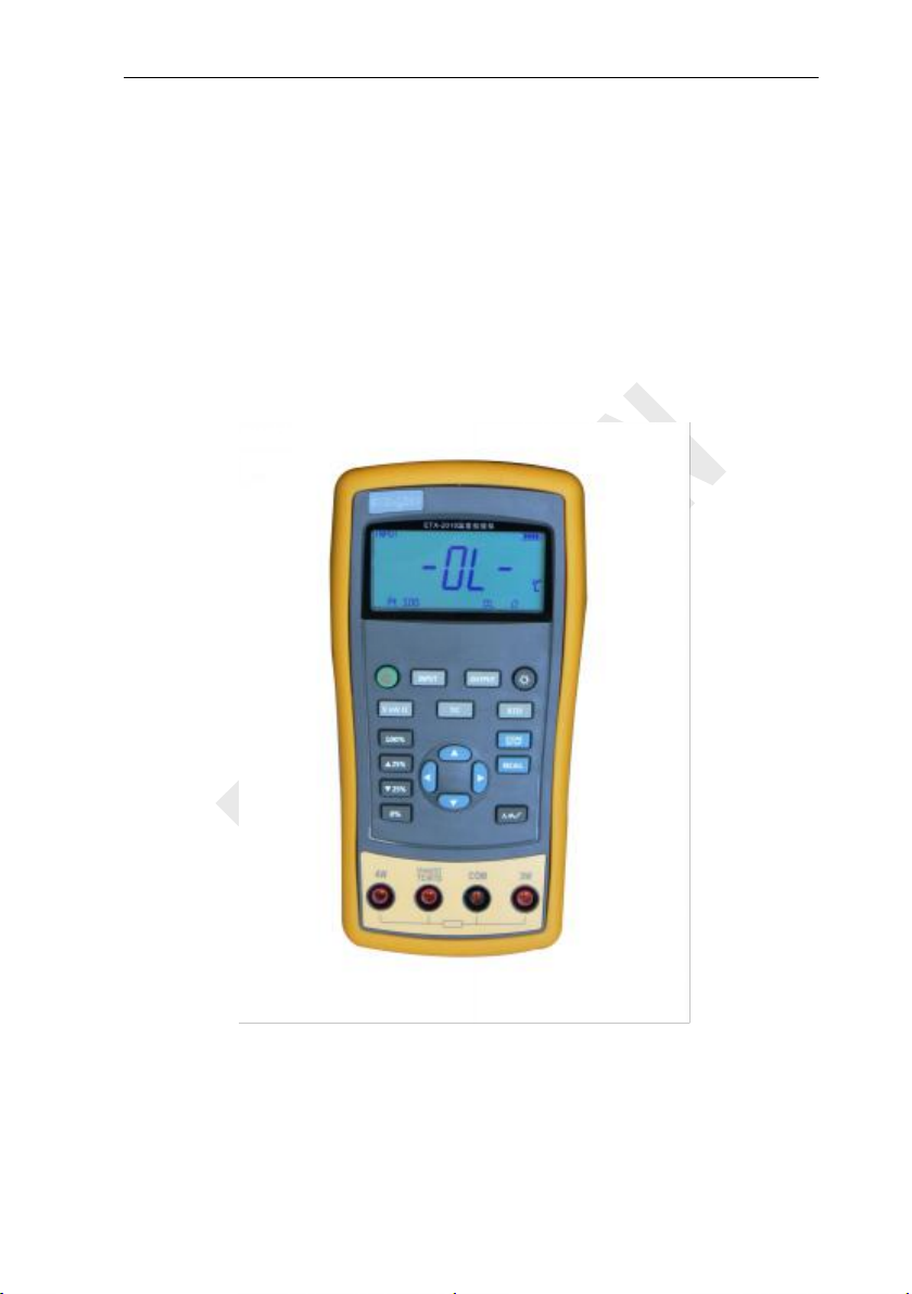
Temperature Calibrator
Users Manual
Model No.: BRT 2010
Shenzhen Brightwin Technology Co., Ltd.
Page 2

Contents
1 Basic Introduction
1.1 Function
1.2 Summary of Source and Measure Functions
1.3 Terminal Description
1.4 Key Description
1.5 Display Screen
2 Basic Operation
2.1 Measure and Source
2.2 Shutdown Mode
2.3 Backlight Brightness Adjustment
3 Function Usage
3.1 DC V Measurement
3.2 DC mV Measurement
3.3 Resistance Measurement
3.4 DC mV Output
3.5 Resistance Output
4 Temperature Measurement
4.1 Using Thermocouple (TC)
4.2 Using Resistance Thermometer Detector (RTD)
5 Simulation of temperature sensor
5.1 Simulating Thermocouples
5.2 Application of Resistance Temperature Detector (RTD)
6 Advanced Application
6.1 Setting 0 % and 100 % output parameters
6.2 Auto Ramping the Output
6.3 Factory Reset
7 Power
8 Specifications
...........................................................................................................................
7.1 Charge
8.1 DC Voltage Measurement
........................................................................................................
.............................................................................................................
.........................................................................................
.................................................................................................
..................................................................................................
............................................................................................................
........................................................................................
................................................................................................
....................................................................
............................................................................................................
..........................................................................................
....................................................................................
.............................................................................
.................................................................................................
..........................................................................................
......................................................................................
.............................................................................
...........................................................................
...........................................................................
................................................................................................
................................................
..............................................................................
..................................................................................................
.............................................................................................................
.............................................................................................................
.............................................................................
...............................................
......................................
..........................
1
1
1
2
3
4
5
5
7
8
9
9
10
10
11
12
13
13
15
18
18
19
20
20
21
21
22
22
23
23
Page 3

8.2 DC Voltage Source
8.3 Resistance Measurement
8.4 Resistance Output
8.5 Temperature, TC
8.6 Temperature, RTD
9 Product Accessories
9.1 Standard Accessories
9.2 Optional accessories
10 Warning
.....................................................................................................................
..................................................................................................
.........................................................................................
.............................................................................
..........................................................................................
.............................................................................................
..........................................................................................
....................................................................................
.....................................................................................
23
24
24
25
26
27
27
27
28
Page 4

BRIGHTWIN BRT 2010 TEMPERATURE CALIBRATOR
It allows you to measure DC V, DC mV, resistance ,TC and RTD.
Outputs resistance, simulation of TC and RTD.
Thermocouple (TC) measurement provides cold-junction compensation.
Manual stepping, automatic stepping, 0 ~ 100% phase step and ramp
Super-strong protection: The waterproof grade is IP67. Automatic
Support for PC communication
Function
Measure
Source
DC V
0~30V
Not available
DC mV
0~120mV
0mV~100mV
Resistance
0~3200Ω
0~3200Ω
RTD
Pt100, Pt1000, Cu50,
Cu100
Pt100, Pt1000, Cu50, Cu100
TC
E,J,K,T,B,R,S,N
E,J,K,T,B,R,S,N
Others
Stepping output, ramp, phase step output, user-defined range
1 Basic Introduction
1.1 Function
output.
protection against the signal terminals connect to the 220V.
1.2 Summary of Source and Measure
Functions
Page 5
BRIGHTWIN BRT 2010 TEMPERATURE CALIBRATOR
No.
Name
Description
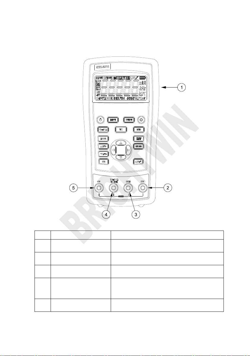
①
Communication and
charging connector
Connect power adaptor to charge batteries or connect
the calibrator to the computer.
②
3W and 4W terminal
3-wire and 4-wire electric and thermal resistance
measurement terminal.
③
COM Public terminal
terminal
All measurement and output public terminal.
④
V, mV, Ω,TC and RTD
terminal
Voltage and DC mV, 2-wire resistance,
thermal-electric and resistance measurement as well
as DC mV, resistance, thermocouple and
thermal-resistance output terminal.
⑤
4W+ terminal
Resistance and thermal resistance 4-wire
measurement terminal.
1.3 Terminal Description
Figure 1.3-1
Page 6
BRIGHTWIN BRT 2010 TEMPERATURE CALIBRATOR
No.
Description
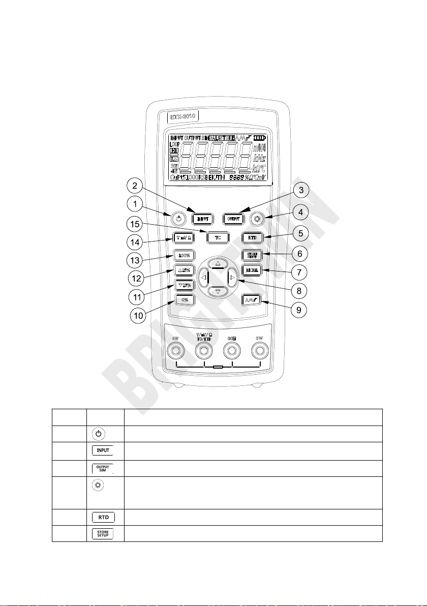
①
Turns the power on or off
②
Selects the measurement mode
③
Selects output and analog transmitter mode.
④
Enables backlight switch display during start, enters backlight
brightness control mode.
⑤
Selects thermal resistance mode
⑥
Sets and saves calibrator parameters setting
1.4 Key Description
Figure 1.4-1
Page 7
BRIGHTWIN BRT 2010 TEMPERATURE CALIBRATOR
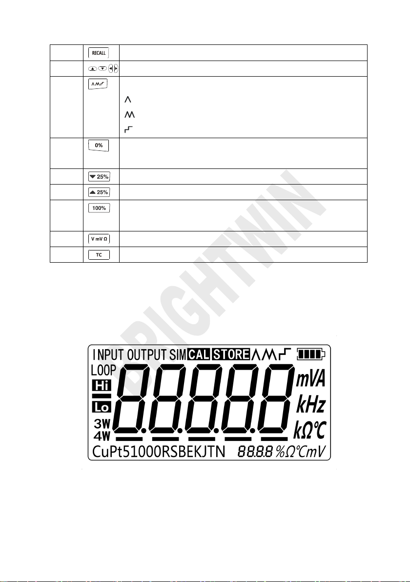
⑦
Recovers factory default setting
⑧
Sets manual output
⑨
Cycles through:
slow repeating 0%-100%-0% ramp
Fast repeating 0 % - 100 % - 0 % ramp
Repeating 0 % - 100 % - 0 % ramp in 25 % steps
⑩
Set output by 0% of span, Press and hold to store the source
value as the 0 % value
⑾
Decrements output by 25% of span.
⑿
Increments output by 25% of span.
⒀
Sets output by 100% of span, Press and hold to store the
source value as the 100 % value.
⒁
Sets voltage, DC mV and resistance mode
⒂
Selects thermo-couple mode
1.5 Display Screen
Figure 1.5-1
Page 8
BRIGHTWIN BRT 2010 TEMPERATURE CALIBRATOR
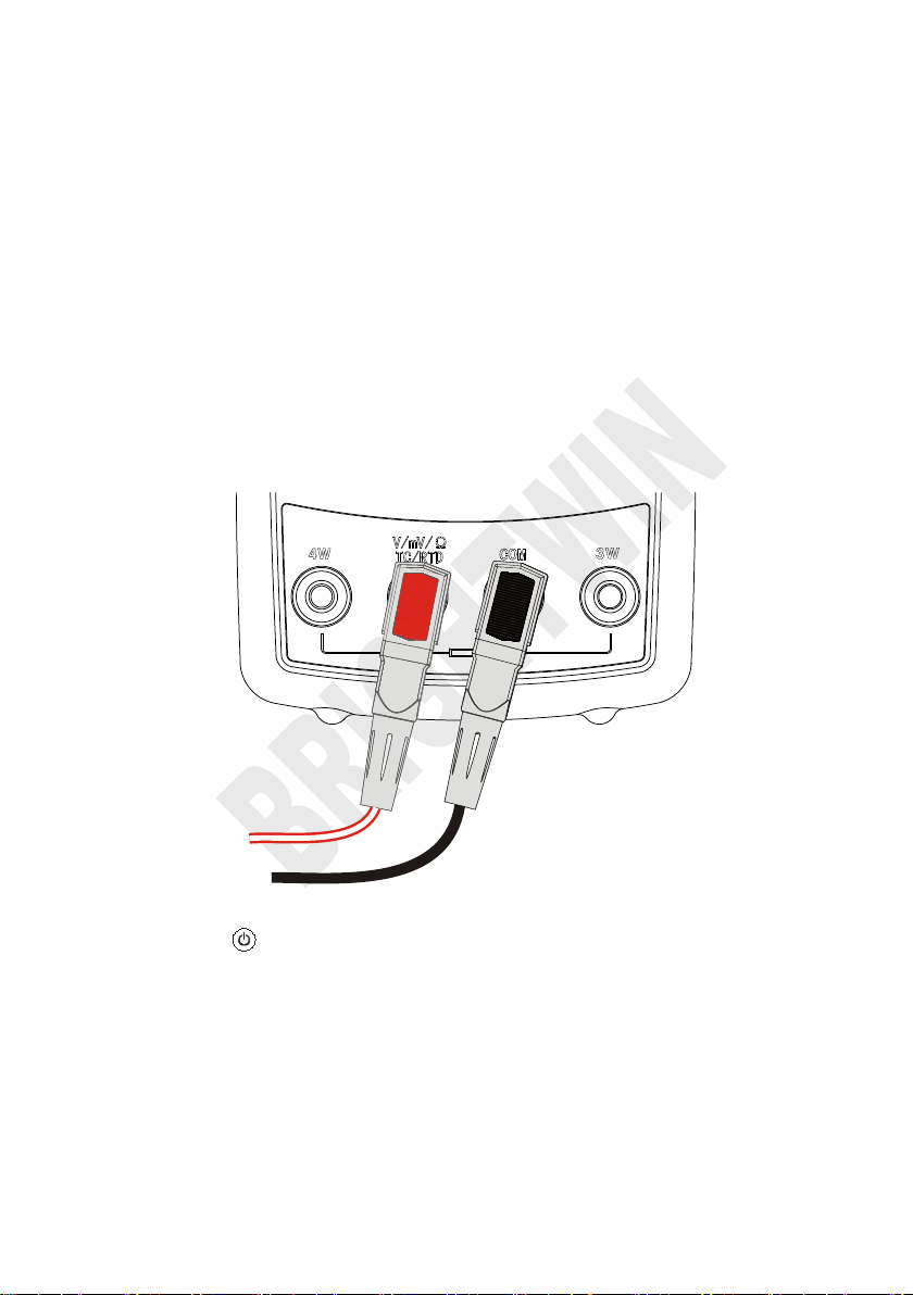
1. The connection of the calibrator as shown in Figure 2.1-1.
2. Press more than 2 seconds to turn on the calibrator. The calibrator
2 Basic Operation
2.1 Measure and Source
This section acquaints you with some basic operations of BRT-2010/
BRT-1810.
Proceed as follows:
Figure 2.1-1
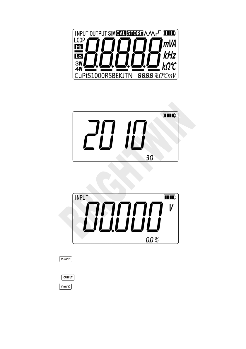
checks itself, including check on internal circuit and LCD, during which,
LCD displays all contents for 1s as shown in Figure 2.1-2:
Page 9
BRIGHTWIN BRT 2010 TEMPERATURE CALIBRATOR
3. Then the product model(2010) and automatic shutdown time(30 min)
4. Then the default interface of boot will be displayed as shown in Figure
5. Press , switch to the voltage mode. Switching is not required for this
6. Press to enter into output mode selection
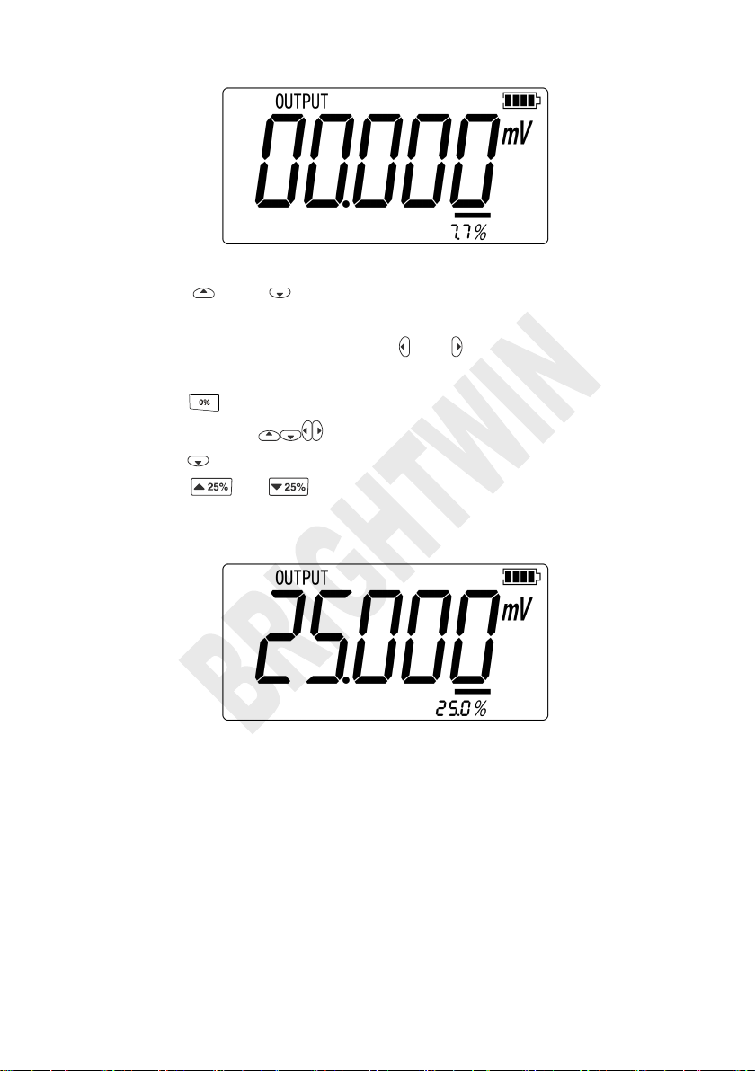
7. Press to enter into DC mV output mode as shown in Figure 2.1-5.
Figure 2.1-2
will be displayed for 2 seconds as shown in Figure 2.1-3.
Figure 2.1-3
2.1-4:
Figure 2.1-4
series after starting-up.
Page 10
BRIGHTWIN BRT 2010 TEMPERATURE CALIBRATOR
8. Press and to increase or decrease 1 of the horizontal line
9. Press until the buzzer works and to enter 0mV as 0% value.
10. Likewise, press to increase output value to be 100mV, and then
11. Press or to make output increase or decrease within the
Figure 2.1-5
position (the number will be based on automatic stepping without change
of horizontal line position); press or to change the position of
horizontal line.
press until the buzzer works and enter 100mV as 100% value.
span of 0% to 100% based on 25% advance amplitude. The screen will
display as shown in Figure 2.1-6.
Figure 2.1-6
2.2 Shutdown Mode
The calibrator comes with the shutdown mode enabled for a time duration set to
30 minutes (displayed for about 2 seconds when the calibrator is initially turned
on). When the shutdown mode is enabled, the calibrator will automatically
Page 11
BRIGHTWIN BRT 2010 TEMPERATURE CALIBRATOR
1. Please press and simultaneously until the buzzer work, then the
2. Press and to adjust the brightness of backlight.
3. Press to save brightness level, will appear and then the
shutdown after the time duration has elapsed from the time the last key was
pressed. To disable the shutdown mode, press and simultaneously. To
enable the mode, press and simultaneously. To adjust the time duration,
press and simultaneously, the screen will display as shown in Figure
2.2-1,then press and/or to adjust the time between 1 and 30 minutes
and then press to store the new time duration (Without pressing any key
for 5 seconds, the calibrator will quit from the adjustment automatically).
Figure 2.2-1
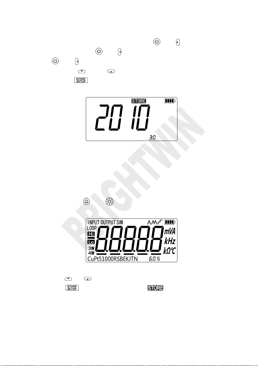
2.3 Backlight Brightness Adjustment
To adjust the brightness of backlight, proceed as follows:
screen will display as shown in Figure 2.3-1:
Figure 2.3-1
calibrator will enter into the work mode(Without pressing key for 5 seconds,
the calibrator will exit from the adjustment automatically).
Page 12
BRIGHTWIN BRT 2010 TEMPERATURE CALIBRATOR
3 Function Usage
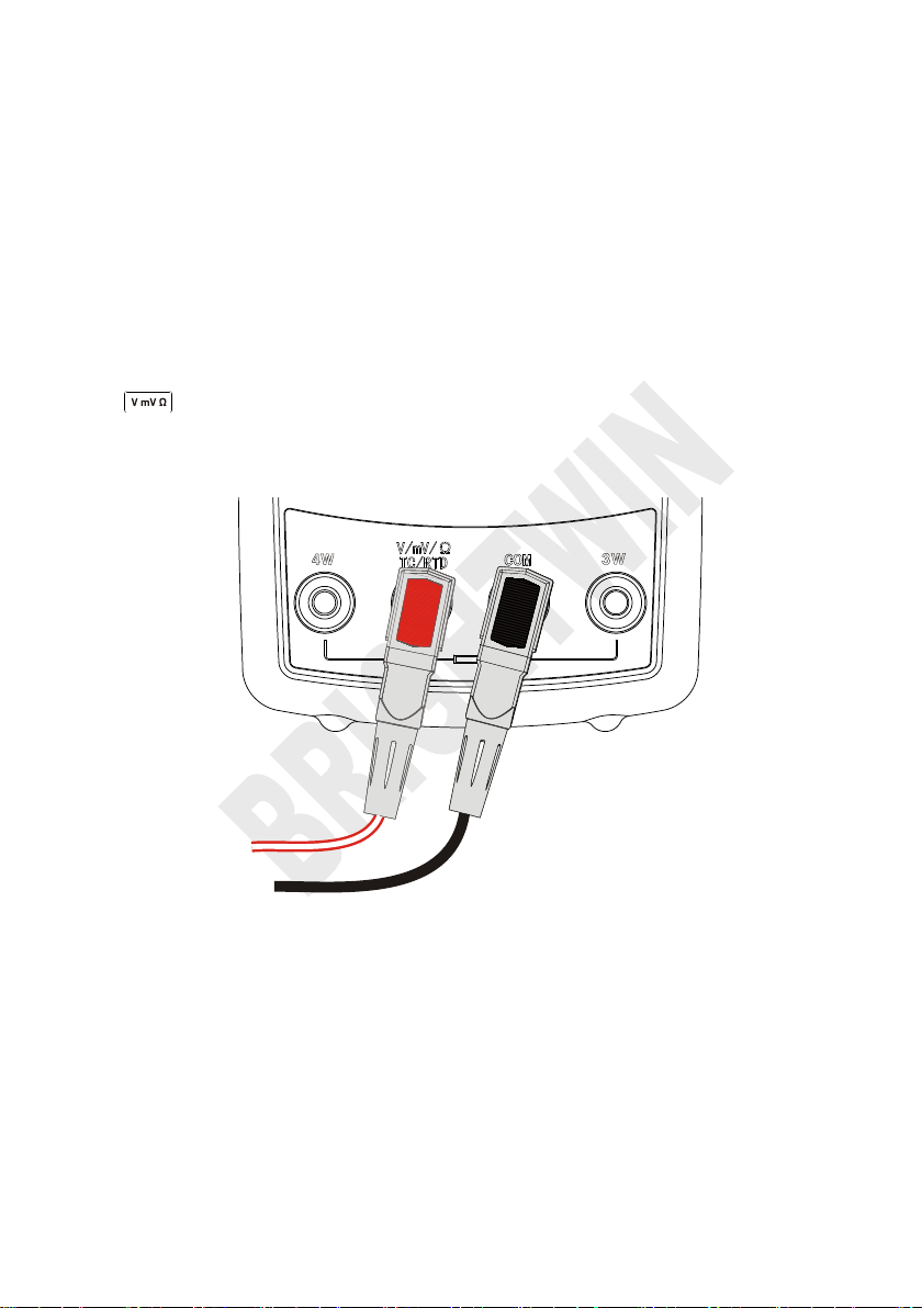
3.1 DC V Measurement
The default function after turn on is DC V measurement. If it is required, press
to re-select the voltage measurement (the display unit is V).Please
connect the lines after all functions are selected. The connection mode and
interface are shown in Figure 3.1-1:
Figure 3.1-1
Page 13
BRIGHTWIN BRT 2010 TEMPERATURE CALIBRATOR
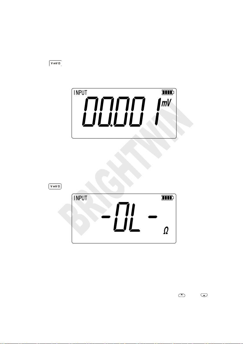
3.2 DC mV Measurement
Press to re-select the DC mV function (the display unit is DC mV), the
connection mode is same to that of voltage measurement. The screen will
display as shown in Figure 3.2-1.
Figure 3.2-1
3.3 Resistance Measurement
Press to reselect the DC mV measurement function (Display unit is Ω)
Figure 3.3-1
The Over Span Under Open Circuit
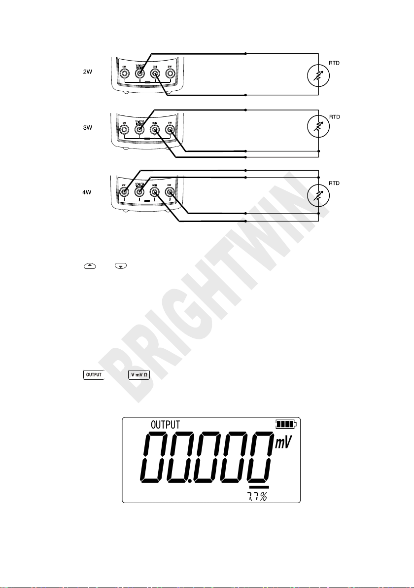
Resistance measurement supports the connection type of two-wire system,
three-wire system and four-wire system. The calibrator can be switched to
three-wire system or four-wire system according to actual connecting type. The
respective connecting types are listed in Figure 3.3-2: Press and to
select the connection mode forcibly.
Page 14
BRIGHTWIN BRT 2010 TEMPERATURE CALIBRATOR
Figure 3.3-2
Press or to force the calibrator to adopt two-wire system, three-wire
system or four-wire system. Afterwards, the calibrator will not detect connecting
type automatically unless you quit the mode of resistance measurement and
re-enter.
3.4 DC mV Output
Press and to select DC mV output function, the connection mode
is same to that of voltage measurement. The screen will display as shown in
Figure 3.4-1.
Figure 3.4-1
Page 15
BRIGHTWIN BRT 2010 TEMPERATURE CALIBRATOR
3.5 Resistance Output
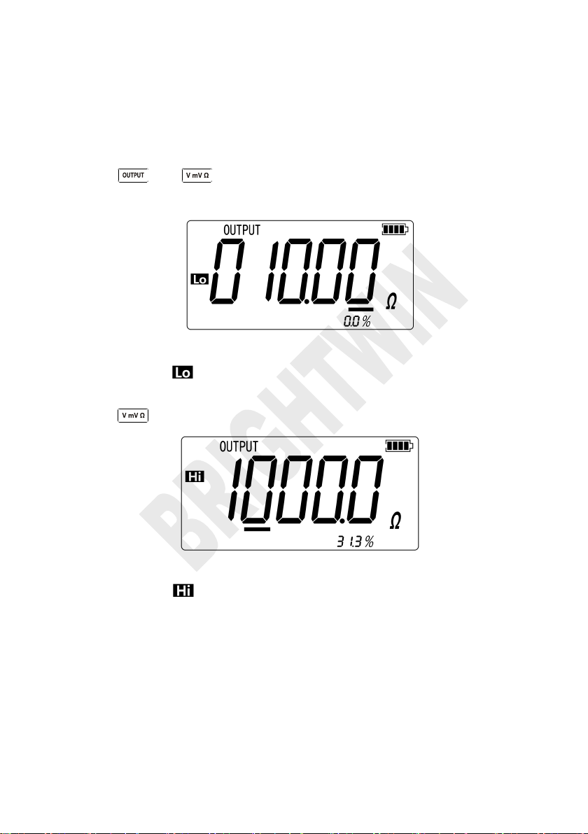
Press and to select the resistance output function, the connection
mode is same to that of voltage measurement.
Figure 3.5-1
indicates the undersize of exciting current,
meanwhile, the main value flashes
Press to select resistance output at 3200Ω level.
Figure 3.5-2
indicates the oversize of exciting current,
meanwhile, the main value flashes
Page 16

BRIGHTWIN BRT 2010 TEMPERATURE CALIBRATOR
Graduation
Positive lead
material
Positive wire (H)
color
Negative lead
material
Specified
span℃
ANSI*
IEC**
E
Chrome-nick
el
Mauve
Purple
Constantan
-200~950
N
Nickel-chrom
e-silicon
Orange
Pink
Nickel-silicon-magn
esium
-200~1300
J
Iron
White
Black
Constantan
-200~1200
K
Chrome-nick
el
Yellow
Green
Alumel
-200~1370
T
Copper
Blue
Brown
Constantan
-200~400
B
Platinum
(30%
rhodium)
Grey
Platinum (6%
rhodium)
600~1800
R
Platinum
(13%
rhodium)
Black
Orang
e
Platinum
-20~1750
S
Platinum
(10%
rhodium)
Black
Orang
e
Platinum
-20~1750
* Negative conductor (L) regulated as American National Standard (ANSI) is always red.
*Negative conductor (L) regulated as International Electro-technical Commission (L) is always
white.
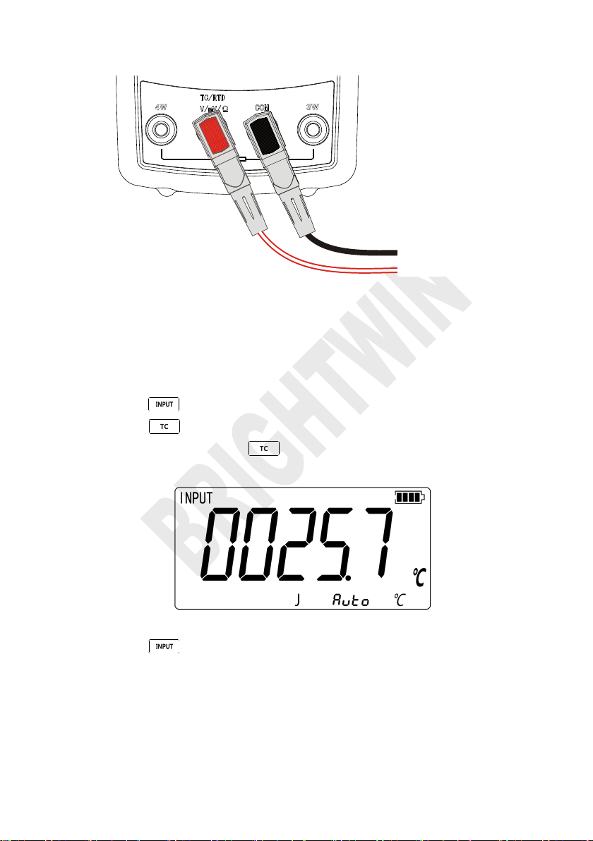
1. Connect the thermocouple to the calibrator as shown in Figure 4.1-1:
4 Temperature Measurement
4.1 Using Thermocouple (TC)
The calibrator supports eleven standard thermocouples, including J, K, T, E, R,
S, B, L, U and N. Lower table summarizes the ranges and characteristics of the
supported thermocouples
To measure temperature using thermocouple, the following steps shall be
followed:
Page 17
BRIGHTWIN BRT 2010 TEMPERATURE CALIBRATOR
2. Press to select measurement mode.
3. Press to display thermocouple reading as shown in Figure 4.1-2. If
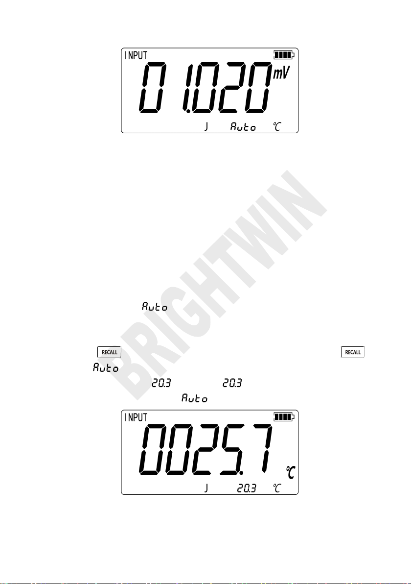
4. Press to display the DC mV value reading as shown in Figure 4.1-3.
Process temperature
Figure 4.1-1
Attention:
Under different calibrator-thermocouple temperature environment, you
shall wait for one minute to stabilize the plug temperature after
connecting TC to input & output wiring.
necessary, pressing continuously to select appropriate
thermocouple type.
Figure 4.1-2
The DC mV value continue to display for 3s and then automatically return
to the original display .
Page 18
BRIGHTWIN BRT 2010 TEMPERATURE CALIBRATOR
Figure 4.1-3
There are two kinds of cold end temperature compensation for thermocouple
measurement, automatic compensation directly using machine internal cold
end temperature compensation and manual compensation through the key to
set the cold end temperature compensation by the user.
4.1.1 Automatic compensation
First entered the thermocouple measurement mode, the default of the cold end
temperature compensation is automatic compensation reading as shown in
Figure 4.1.1-1.The sign represents that the current cold end
temperature compensation is automatic compensation. If you need further view
current automatic cold end temperature compensation value,you have to
operation key. Reading as shown in Figure 4.1.1-1,after press
key, the sign is replaced for current automatic cold end temperature
compensation value as . The value continue to display for 2s and
then automatically return to the sign.
Figure 4.1.1-1
Page 19
BRIGHTWIN BRT 2010 TEMPERATURE CALIBRATOR
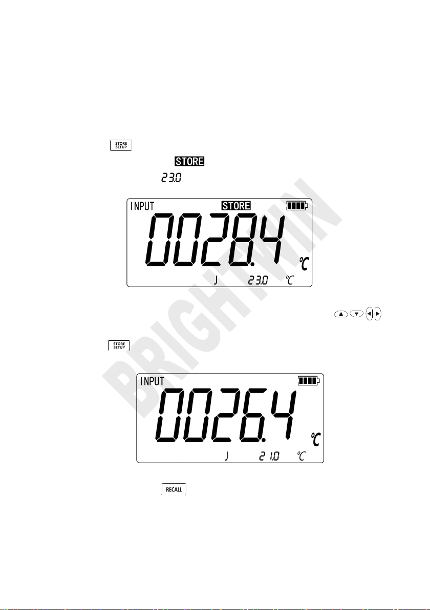
1. Press key to enter the set mode, reading as shown in Figure
2. If you need to adjust the manual compensation value, press
3. Press key to save the value of manual compensation and exit from
4. If necessary, press key return to automatic compensation.
4.1.2 Manual compensation
Manual compensation through the key to set the cold end temperature
compensation by the user, the following steps shall be followed:
4.1.2-1, the appear of sign shows that entering the setup mode,
the assistant value means the value of manual compensation.
Figure 4.1.2-1
keys to adjust.
the setup mode at the same time, reading as shown in Figure 4.1.2-2.
Figure 4.1.2-2
Page 20
BRIGHTWIN BRT 2010 TEMPERATURE CALIBRATOR
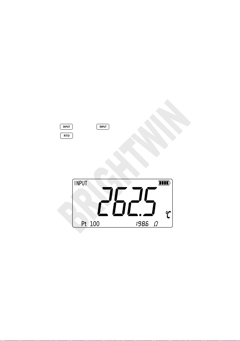
1. Press to select mode.
2. Press for the RTD display. Then the screen will display as shown in
3. Connect RTD to the corresponding port according to the connecting type
4.2 Using Resistance Thermometer
Detector (RTD)
The calibrator accepts Pt100, Pt1000, Cu50 and Cu100, etc. The calibrator
accepts RTD measurements inputs in two-, three-, or four-wire connections,
with the three-wire connection the most common. A four-wire configuration
provides the highest measurement precision, and two-wire provides the lowest
measurement precision.
To measure temperature using an RTD input, proceed as follows:
Figure 4.2-1. If desired, continue pressing this key to select the desired
RTD type.
of ‘resistance measurement’.
Figure 4.2-1
Page 21
BRIGHTWIN BRT 2010 TEMPERATURE CALIBRATOR
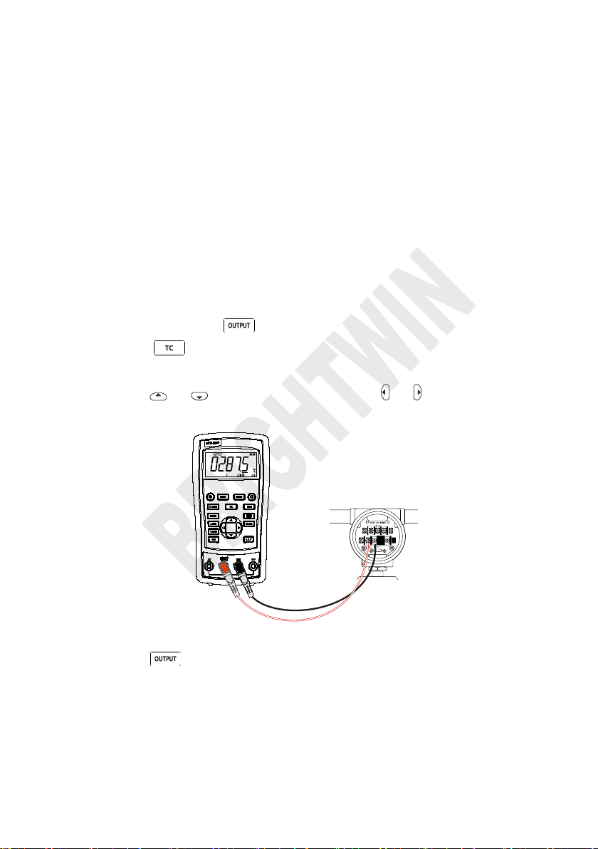
1. Connect thermocouple to the TC input/output plughole of calibrator as
2. If necessary, press to select output mode.
3. Press to select thermocouple function. If necessary, continue
4. Press or to select temperature. Press or to select digit.
5. Press to display the DC mV value, which continue to display for 3s
5 Simulation of temperature sensor
5.1 Simulating Thermocouples
Connect calibrator input/output terminal to the instrument to be tested using
thermocouple. The connecting diagram is shown below, Proceed as follows to
simulate a thermocouple:
shown in Figure 5.1-1.
pressing the key to select thermocouple graduation.
Figure 5.1-1
and then automatically return to the original display .
Simulating Thermocouples also have two kinds of cold end temperature
compensation, automatic and manual compensation.The method of operation is
Page 22
BRIGHTWIN BRT 2010 TEMPERATURE CALIBRATOR
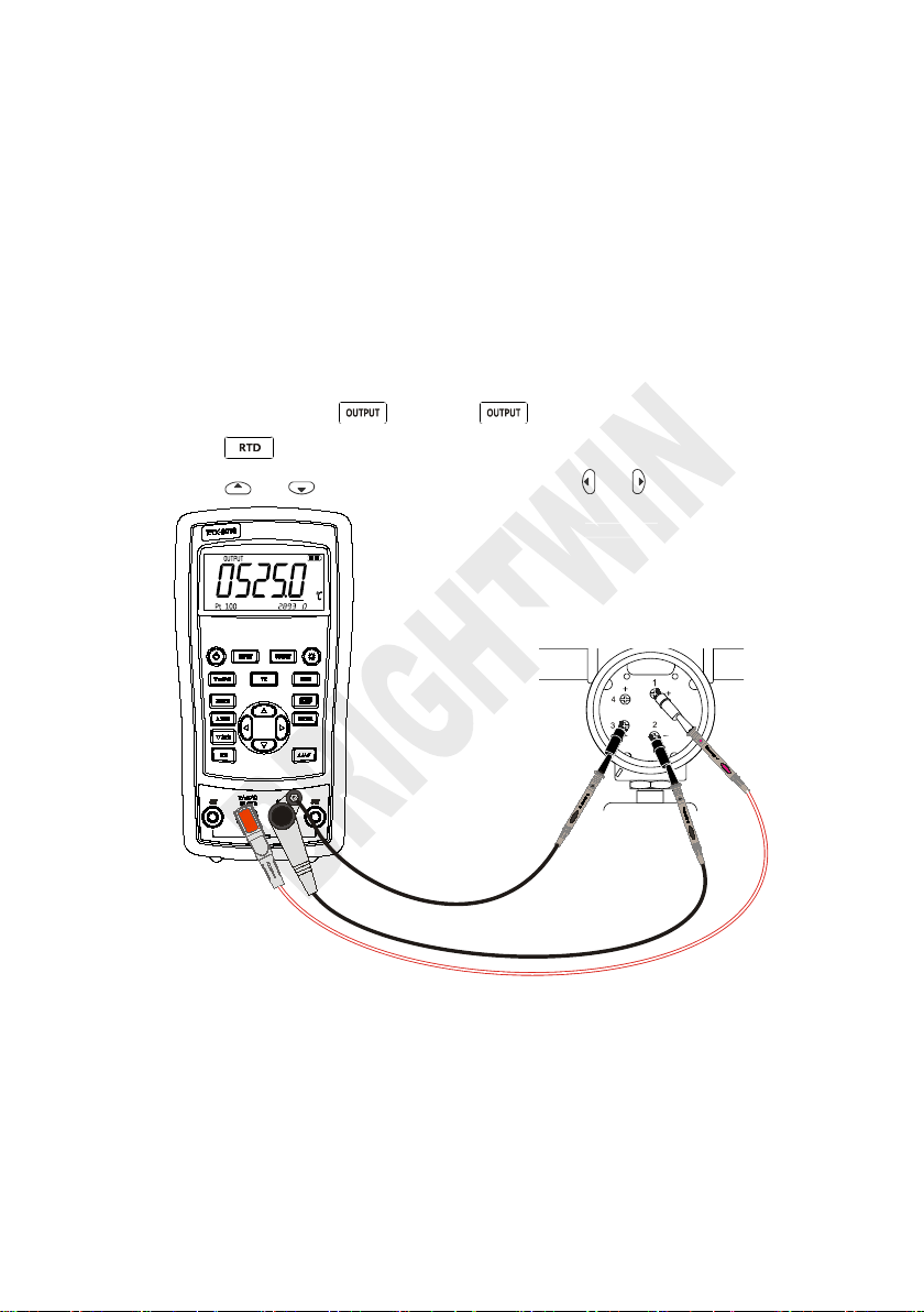
1. If necessary, press to select mode.
2. Press to select RTD graduation.
3. Press or to select temperature. Press or to select digit.
Sensor terminal of transducer
same to using thermocouple,please refer to 4.1 section for specific operation.
5.2 Application of Resistance
Temperature Detector (RTD)
Connect the calibrator and the instrument to be tested according to the Figure
5.2-1. Simulation of RTD should be based on the following steps:
Three-wire (3 W) and four-wire (4 W) terminals are just for measurement, not
output simulation. The calibrator can simulate a two-wire RTD output in the front
panel. To be connected to a three-wire or four-wire transducer, use folding
cable to provide extra wiring.
Figure 5.2-1
Page 23
BRIGHTWIN BRT 2010 TEMPERATURE CALIBRATOR
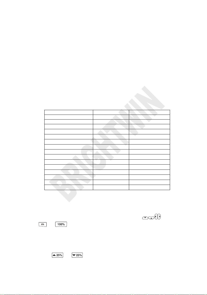
Output Function
0% value
100% value
DC mV
0.00 mV
100.00 mV
Resistance 400Ω
0.00 Ω
400.00 Ω
Resistance 3200Ω
0.0 Ω
3200.0 Ω
Thermocouple J type
0.0 ℃
1000.0 ℃
Thermocouple K type
0.0 ℃
1000.0 ℃
Thermocouple T type
0.0 ℃
400.0 ℃
Thermocouple E type
0.0 ℃
800.0 ℃
Thermocouple R type
0 ℃
1500 ℃
Thermocouple S type
0 ℃
1500 ℃
Thermocouple B model
600 ℃
1800 ℃
Thermocouple N model
0.0 ℃
1000.0 ℃
Pt100
0.0 ℃
500.0 ℃
Pt1000
0.0 ℃
400.0 ℃
Cu50
0.0 ℃
150.0 ℃
Cu100
0.0 ℃
150.0 ℃
Press or for manual steeping (increase or decrease) output
6 Advanced Application
6.1 Setting 0 % and 100 % output
parameters
As for stepping operation and percentage display, 0% and 100% should be set
before using. Some gear values have been set when delivered from the factory
and set values are illustrated below:
The default set values may not meet your requirements, so you can reset them.
Then you can display the percentage with stepping or ramp output as well as
display the percentage. Adjust the output value with keys , press and
hold or for a long time until the buzzer sends a “Ticking” sound to
define the new 0% or 100% values. The new defined span value is saved in the
calibrator storage automatically and remains effective after restart. The flowing
operations are available with the setting:
Page 24

BRIGHTWIN BRT 2010 TEMPERATURE CALIBRATOR
Press or instantly to make output jump within the span of 0%
0%-100%-0% 40-second smooth ramp
0%-100%-0% 15-second smooth ramp
0%-100%-0% Stair-step ramp in 25 % steps, pausing 5 seconds at
The working status recovers to the voltage measurement.
Automatic shutdown time is reset to be 30 min, which is effective.
LCD backlight brightness is set to be 60%.
Output span is recovered to be factory default.
based on 25% increment.
to 100%.
6.2 Auto Ramping the Output
Automatic ramping gives you the ability to continuously apply a varying stimulus
from the calibrator to a transmitter, while your hands remain free to test the
response of the transmitter.
When you press , the calibrator produces a continuously repeating 0 % -
100 % - 0 % ramp in your choice of three ramp waveforms:
each step.
Exit the slop output function, please press any key.
6.3 Factory Reset
Factory reset consists of the following items:
Start the calibrator and press until the buzzer works, and the recovery of
factory default will enter working mode when the recovery is completed.
Page 25

BRIGHTWIN BRT 2010 TEMPERATURE CALIBRATOR
Disposable batteries are used.
Electric quantity is enough.
7 Power
The calibrator needs 6 disposable LR03 model (size 7) alkaline batteries or 6
R03 model (size 7) nickel-metal hydride batteries (or nickel-cadmium batteries).
The longest service life of alkaline batteries can reach 50 hours.
A 12V/1A power adaptor is used for charging and providing working power for
the calibrator.
7.1 Charge
When the battery indicator is pointed at , the remaining electric quantity is
less than 20%. Charge is necessary for normal operation of the calibrator. The
LCD backlight will start operation and the will display on the screen when
the power adaptor is used. If the battery indicator flashes, the calibrator
will be in the charging process, after which the battery indicator will stop
flashing.
The calibrator will stop charge automatically in case of the following
circumstances:
Page 26

BRIGHTWIN BRT 2010 TEMPERATURE CALIBRATOR
Range
Maximum
measurement
range
Resolution
Accuracy (% of reading +
Counts)
BRT-1810
BRT-2010
30V
0V~31V
0.001V
0.05+2
0.02+2
100mV
-15mV~80mV
0.001mV
0.05+20
0.02+20
80mV~125mV
0.01mV
0.05+2
0.02+2
-10℃~18℃,+28℃~55℃temperature coefficient,±0.005%FS/℃.
Input resistance:>1MΩ.
Range
Maximum output
range
Resolution
Accuracy (% of reading +
Counts)
BRT-1810
BRT-2010
100mV
-15mV~99.999mV
0.001mV
0.05+20
0.02+20
100mV~125mV
0.01mV
0.05+2
0.02+2
-10℃~18℃,+28℃~55℃temperature coefficient,±0.005%FS/℃.
Maximum load: 1mA or 1kΩ(It should be based on the lower load.
)
8 Specifications
Specifications are based on a one year calibration cycle and apply from +18℃
to +28 ℃ unless stated otherwise. All specifications assume a 10 minute warm
up period.
8.1 DC Voltage Measurement
8.2 DC Voltage Source
Page 27

BRIGHTWIN BRT 2010 TEMPERATURE CALIBRATOR
Range
Maximum
measurement
range
Resolution
Accuracy (Ω)
BRT-1810
BRT-2010
2-wire,
3-wire
4-wire
2-wire,
3-wire
4-wire
400Ω
0~440Ω
0.01Ω
0.25
0.15
0.15
0.10
3200Ω
420Ω~3600Ω
0.1Ω
1.5
1.0
1.0
0.5
-10℃~18℃,+28℃~55℃temperature coefficient,±0.005%FS/℃.
Exciting current during measurement:
400Ω:1.0mA±10%;
3200Ω:0.2mA±10%;
Two-wire: Conductor resistance is excluded from errors.
Three-wire: Matching test line should be used. The total resistance of conductor should not be
larger than 25Ω.
Range
Maximum
output range
Resolutio
n
External exciting
current
Accuracy (Ω)
BRT-1810
BRT-2010
400Ω
0~440Ω
0.01Ω
0.4mA~4.0mA
0.25
0.15
3200Ω
400~3600Ω
0.1Ω
0.1mA~0.5mA
1.0
0.50
-10℃~18℃,+28℃~55℃temperature coefficient,±0.005%FS/℃.
8.3 Resistance Measurement
8.4 Resistance Output
Page 28

BRIGHTWIN BRT 2010 TEMPERATURE CALIBRATOR
Graduation
Range
Resolution
Accuracy (Ω)
BRT-1810
BRT-2010
J
-200℃~0℃
0℃~1200℃
0.1℃
1.5℃
1.0℃
1.0℃
0.7℃
K
-200℃~0℃
0℃~1370℃
0.1℃
1.8℃
1.2℃
1.2℃
0.8℃
T
-200℃~0℃
0℃~400℃
0.1℃
1.8℃
1.2℃
1.2℃
0.8℃
E
-200℃~0℃
0℃~950℃
0.1℃
1.5℃
1.0℃
0.9℃
0.7℃
R
-20℃~0℃
0℃~500℃
500℃~1750℃
0.1℃
4℃
2.5℃
2℃
2.5℃
1.8℃
1.4℃
S
-20℃~0℃
0℃~500℃
500℃~1750℃
0.1℃
4℃
2.5℃
2℃
2.5℃
1.8℃
1.5℃
B
600℃~800℃
800℃~1000℃
1000℃~1800℃
0.1℃
3.5℃
2.5℃
2℃
2.2℃
1.8℃
1.4℃
N
-200℃~0℃
0℃~1300℃
0.1℃
2.0℃
1.2℃
1.5℃
0.9℃
Errors of cold-junction compensation are not included in the table.
Accuracy of cold-junction compensation: 1.5
℃
8.5 Temperature, TC
Page 29

BRIGHTWIN BRT 2010 TEMPERATURE CALIBRATOR
Graduatio
n
Range
Resolution
Accuracy (℃)
BRT-1810
BRT-2010
2-wire
3-wire
4-wir
e
Output
2-wire
3-wire
4-wire
Output
Pt100
-200℃~
850℃
0.1℃
0.7
0.4
0.7
0.4
0.3
0.3
Pt1000
-200℃~
650℃
0.4
0.3
0.3
0.3
0.15
0.15
Cu50
-50℃~
150℃
1.2
0.8
0.8
0.8
0.5
0.5
Cu100
-50℃~
150℃
0.7
0.4
0.4
0.4
0.25
0.25
As for exciting current during measurement, please refer to resistance measurement function.
As for allowable external exciting current during output, please refer to resistance output
function.
2-wire: Does not include lead resistance.
3-wire: Assumes matched leads with a total resistance not exceeding 25Ω.
8.6 Temperature, RTD
Page 30
BRIGHTWIN BRT 2010 TEMPERATURE CALIBRATOR
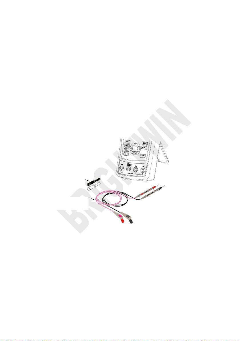
hard spot test leads (one set)
alligator clip (one set)
one 12V/1A power adaptor
BRT-2010/BRT-1810 users manual
6 R03-model rechargeable batteries
1 Metal Box
Communication line
Alligator
Hard spot test leads
9 Product Accessories
9.1 Standard Accessories
A set of BRT-2010/BRT-1810 calibrator also includes the following items:
9.2 Optional accessories
Figure 9.1-1
Page 31

BRIGHTWIN BRT 2010 TEMPERATURE CALIBRATOR
Test a given voltage to confirm its normal operation before using.
Please follow all the safety operation standards.
Select correct function and range gear according to measurement
Confirm the closing of battery door before calibrator application.
Remove the test line of calibrator before opening the battery door.
Check whether damaged or exposed metal exists in the test line and
Fingers should not touch the metal contact when the detector is used.
Connect the common line and then electric test line. As for wire removal,
Don't use the calibrator in case of abnormal operation. Calibrator should
Don’t use the calibrator near explosive gases.
Remove the test line before changing measurement or output function.
6 LR03 (7 size) alkaline batteries or R03 nickel-metal hydride batteries (or
Replace or charge the battery when the screen displays low pressure of
10 Warning
To avoid possible electric shock or personal injury:
requirements.
whether the test line has been conducted. Replace the damaged test line
before using.
Fingers should be behind the finger-protecting device.
electric test line should be first removed.
be repaired because it may have been damaged.
nickel-cadmium batteries) should be used in the calibrator and the battery
should be placed inside the meter housing.
battery, to avoid reading error and possible electric shock or personal
injury.
Page 32

Shenzhen Brightwin Technology Co., Ltd.
Phone: 0086-18126150525 Fax: 0086-755-05464313
Website:www.brightwinelectronics.com E-mail:[email protected]
Zip Code: 518000
Address: #20, 10th AL, Wangtang, Bantian St., Longgang Dist, Shenzhen,
China.
 Loading...