

Page 1

Not for
Reproduction
Installation Instructions
Wireless Monitoring For Standby Generators
Model 6517-00
Call Technical Services 1-833-463-6482
Monday-Friday 8:00 am to 5:00 pm Central Time
Copyright © Briggs & Stratton Corporation
Milwaukee, WI, USA. All rights reserved.
Questions?
Help is just a moment away!
80029482USCN
Revision B
Page 2
Not for
Reproduction
Advanced Monitoring Kit Contents
Keep this document with the generator operator’s manual after
installation is complete.
infohub™ Kit Contents:
• 240V Splitter Harness (A)
• Cellular Unit Wire Harness (B)
• Pass-Through Wire Harness (C)
• Relay Wire (D)
• Interface Board (E)
• Adapter for Liquid-Cooled Unit (F)
• Cellular Unit (G)
• Antenna (H)
• Wire Ties
• Rubber Grommet
A B
Items needed to install the kit:
• Drill with 3/8 inch bit
• Alcohol wipes or other cleaning solution
• Standard and Phillips screwdrivers
• Volt meter or multimeter
• Wire cutter/stripper
• Deburring Tool
• Rust Inhibitor
C
D
E
HGF
2 BRIGGSandSTRATTON.COM
Page 3
Not for
Reproduction
Safety
SAVE THESE INSTRUCTIONS - This installation sheet
contains important safety instructions that should be followed
during installation of the equipment.
Safety Alert Symbol and Signal Words
The safety alert symbol is used to identify safety
information about hazards that can result in personal injury.
A signal word (DANGER, WARNING, or CAUTION) is used
with the alert symbol to indicate the likelihood and potential
severity of injury. In addition, a hazard symbol may be used
to represent the type of hazard.
DANGER indicates a hazard which, if not avoided, will
result in death or serious injury.
WARNING indicates a hazard which, if not avoided, could
result in death or serious injury.
CAUTION indicates a hazard which, if not avoided, could
result in minor or moderate injury.
NOTICE indicates an action that could result in damage to the
product.
Hazard Symbols and Meanings
Electrical Shock
Only qualified, licensed electricians should perform this
installation, which must strictly comply with applicable
codes, standards, and regulations.
WARNING “This product can expose you to chemicals
including gasoline, engine exhaust, which is known to the
State of California to cause cancer and carbon monoxide,
which is known to the State of California to cause birth
defects or other reproductive harm. For more information
go to www.P65Warnings.ca.gov.”
Rotating Parts
Auto Start
WARNING
• DO NOT touch bare wires or bare receptacles.
• DO NOT use generator with electrical cords which are
worn, frayed, bare, or otherwise damaged.
• DO NOT handle generator or electrical cords while
standing in water, while barefoot, or while hands or feet
are wet.
• If you must work around a unit while it is operating,
stand on an insulated dry surface to reduce the risk of a
shock hazard.
• DO NOT allow unqualified persons or children to operate
or service generator.
• In case of an accident caused by electrical shock,
immediately shut down the source of electrical power and
contact the local authorities. Avoid direct contact with the
victim.
• Despite the safe design of the generator, operating this
equipment imprudently, neglecting its maintenance, or
being careless could cause possible injury or death.
• Remain alert at all times while working on this equipment.
Never work on the equipment when you are physically or
mentally fatigued.
• Before performing any maintenance on the generator, first
disconnect the battery cable indicated by a NEGATIVE,
NEG, or (-). When finished, reconnect that cable last.
• After your system is installed, the generator may crank
and start without warning any time there is a power
failure. BEFORE working on the equipment, and to
prevent possible injury, always set the generator system
switch to OFF, remove the service disconnect fuse from
the disconnect box, and remove the 15 Amp fuse.
Generator produces hazardous voltage.
Failure to properly ground generator could result
inelectrocution.
utility power could result in death or serious
injury to electric utility workers, due to backfeed of electrical energy.
Failure to isolate generator from
CAUTION
• Observe that the 15 Amp fuse has been removed from the
control panel before servicing.
• DO NOT install this fuse until all wiring has been
completed and inspected.
Installing the 15 Amp fuse could cause
the engine to start at any time without warning,
resulting in minor or moderate injury.
3
Page 4
Not for
Reproduction
Installation
Thank you for purchasing this home standby accessory.
When installed according to these instructions, the
monitoring device will provide years of dependable service.
Keep your purchase receipt with this instruction sheet and
store with your other generator manuals after installation.
IMPORTANT: Illustrations used in this document are for
reference and may not represent the actual unit being
serviced. Your installation will be similar.
Before starting the installation, refer to Suggested infohub™
Installation Locations at the end of these instructions to
identify your particular type of generator. The preferred
mounting locations for the interface board (E) and the
cellular unit (G) will be shown in those illustrations.
Disconnect Power
WARNING Shock Hazard. Hazardous voltage from utility
service or generator could cause death or serious
Remove all sources of supply voltage and
injury.
follow all disconnect power instructions prior
to performing any service work. Verify with a
meter that utility power has been disconnected.
Before performing any installation, maintenance, or service
on the generator, ALWAYS perform the following steps:
1. Set generator system switch to OFF.
2. Set generator circuit breaker to OFF.
3. Remove 15 Amp fuse from control panel.
4. Utility voltage is present at generator control
panel. Remove the fuses from the transfer switch to
disconnect power before servicing the control panel.
5. Disconnect negative battery cable from negative battery
terminal, indicated by NEGATIVE, NEG, or (-).
NOTICE: Only existing wire harness holes should be used to
route the infohub harness to the generator controller. Except
for the antenna cable hole, it is not necessary to drill other
access holes.
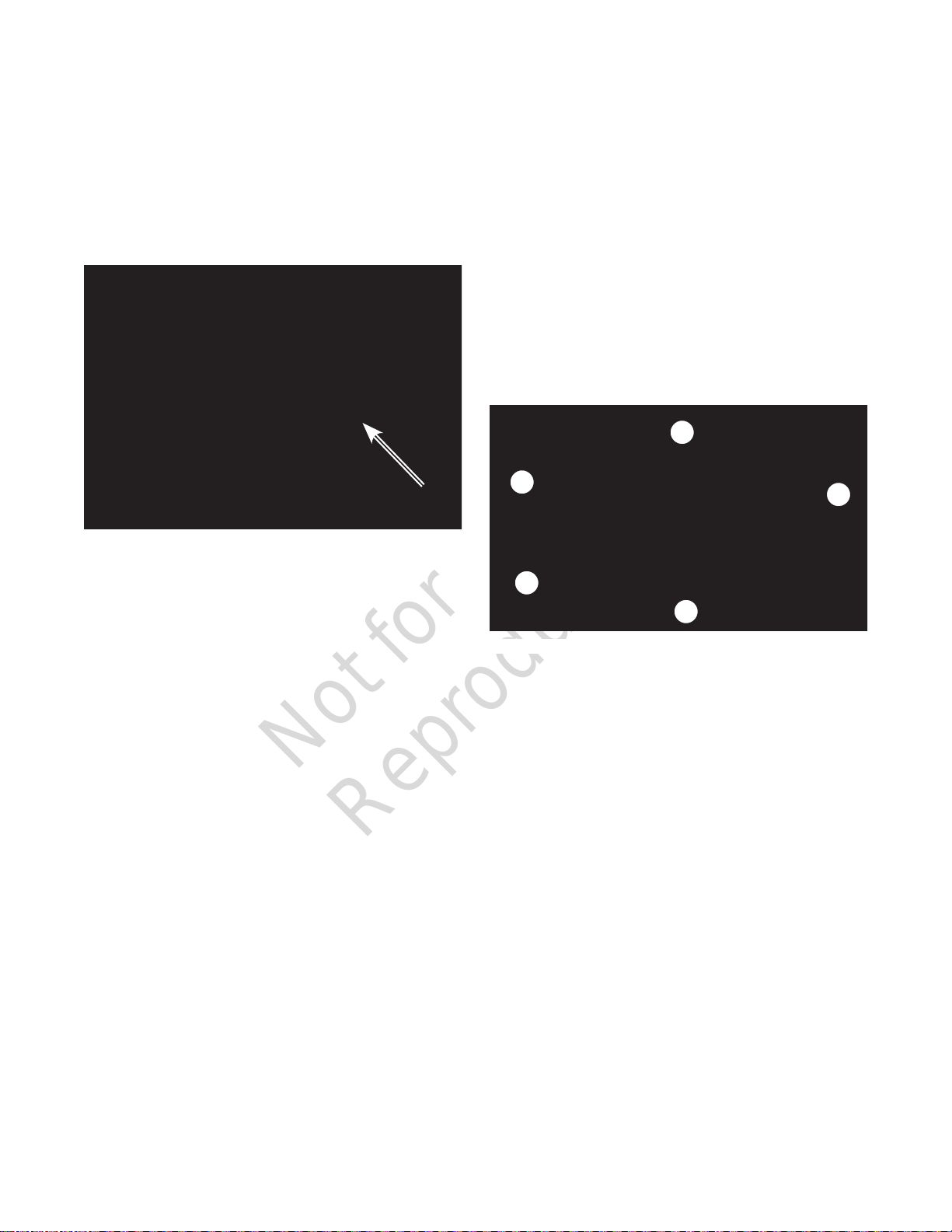
Drill Hole for Antenna Cable
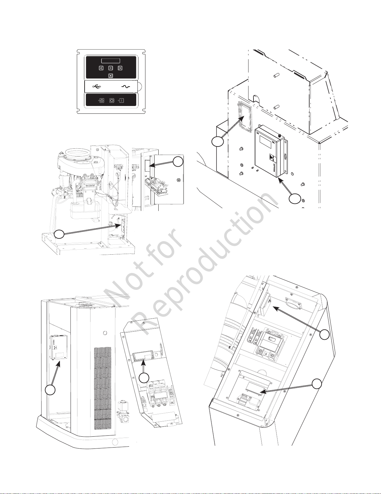
1. Refer to Suggested infohub™ Installation Locations at
the end of these instructions to determine the mounting
location for the cellular unit.
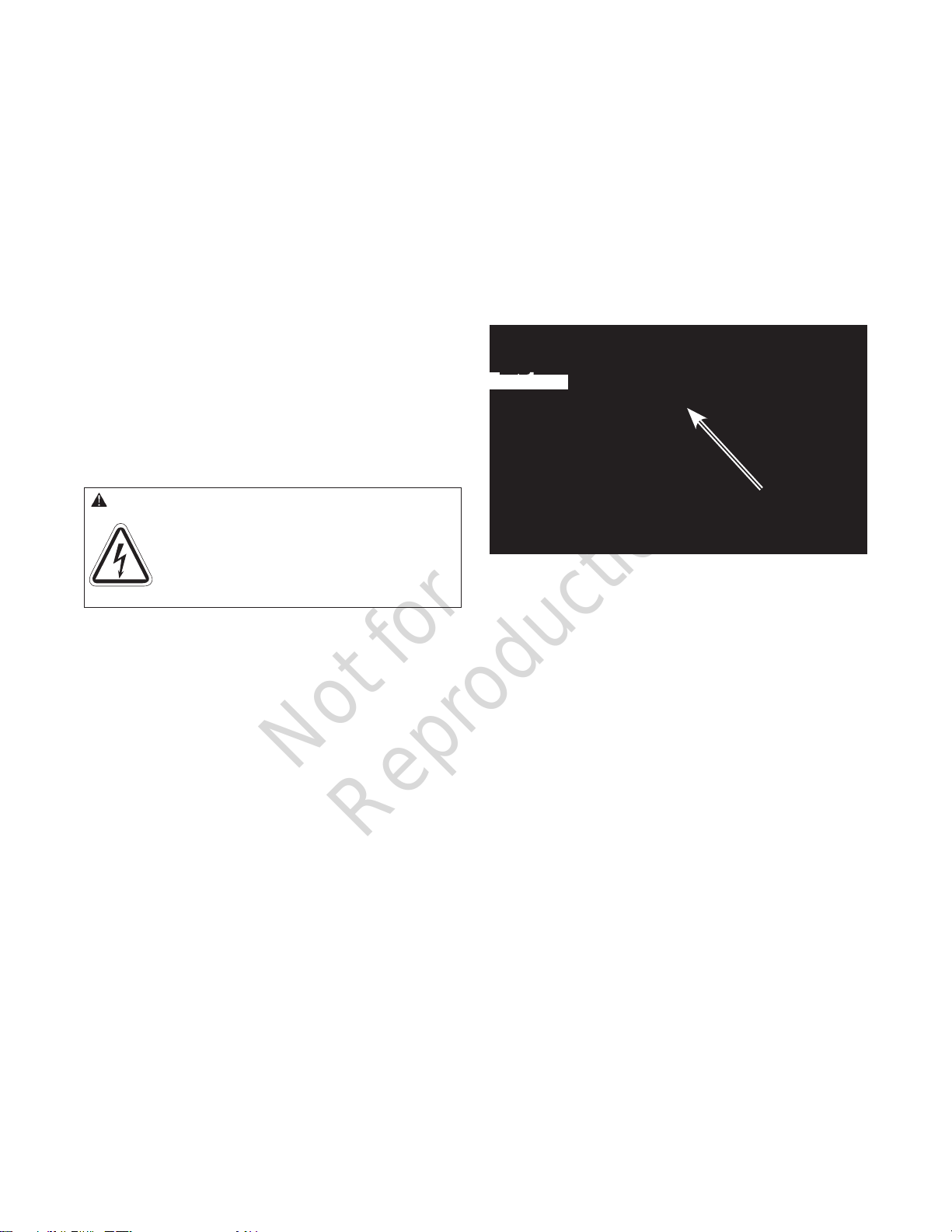
2. Using a 3/8 inch bit, drill a hole into the enclosure near the
intended location of the cellular unit so that the antenna
cable will reach the unit (Figure 1). The hole should
be placed near the roof but not so close as to cause
interference when the roof is fully opened.
Figure 1
3. After drilling the hole, remove any burrs and metal
shavings from the enclosure to prevent rusting.
4. Apply a small amount of rust inhibitor to the inside and
outside of the hole edges and allow to dry.
Mount Antenna to Roof
1. Locate the supplied rubber grommet in the kit.
2. Carefully cut one side to the center of the rubber
grommet. Do not cut in half.
3. When the rust inhibitor is dry on the antenna cable
hole, slip the rubber grommet over the antenna cable,
feed the antenna wire through the hole, and fit the
grommet into the hole.
4A. Mount the magnetic antenna on the generator roof.
4B. For units with plastic or aluminum roofs, use the
supplied washer and adhesive tape
• Find a suitable location on the roof. This location
should be near the antenna cable hole.
• Remove the red adhesive protection film from the
washer and press firmly to the roof.
• Place magnetic antenna on to washer.
.
4 BRIGGSandSTRATTON.COM
Page 5
Not for
Reproduction
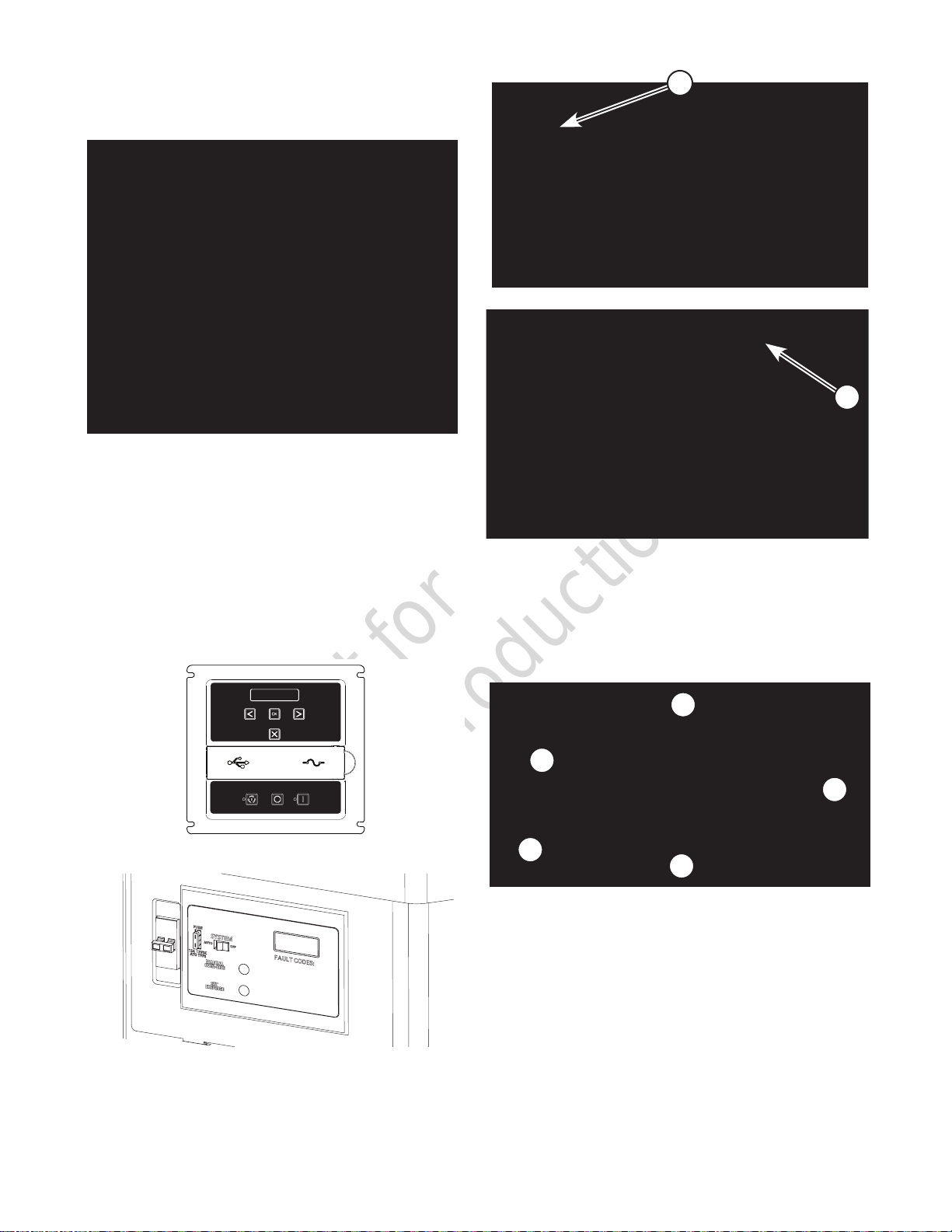
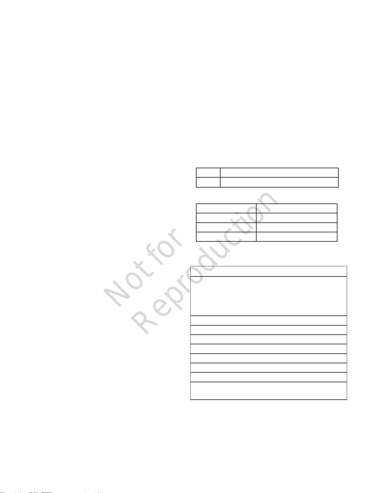
5. On the outside of the enclosure, loop and secure the
antenna cable with a wire tie (Figure 2) to help prevent
water from entering the unit.
Figure 2
6. Route the antenna cable toward the intended mounting
location of the cellular unit.
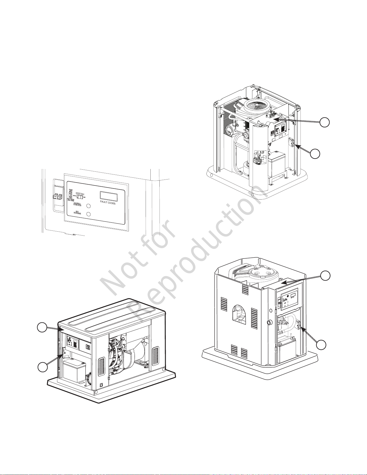
J6
Figure 4A
J6
Disconnect Generator Wire Harness
Verify power is disconnected to the unit before proceeding.
1. Remove the screws and the control box front to access
the control panel. The generator will have either of two
panels (Figure 3A or 3B).
MENU
ESC
AUTO OFF
Figure 3A
Figure 3B
MANUAL
Figure 4B
2. Remove the screws to access the control board on the
back of the panel. The generator will have either of two
control boards (Figure 4A or 4B).
3. Disconnect the generator wire harness (8-wire
connector) from the control board connector J6.
D
C
E
B
A
Figure 5
Identify Interface Board Connections
Locate the supplied interface board in the kit. Before
proceeding, review and understand the interface board
connector assignments below (Figure 5).
A - Generator harness connector from control board
B - Fault relay wire connector
C - 240V splitter harness connector
D - Pass-through harness connector
E - Cellular unit harness connector
5
Page 6
Not for
Reproduction
Install Relay Wire
1. Locate the supplied relay wire in the kit. Determine the
length of wire needed and cut two pieces. Strip the
four ends prior to installation.
2. Insert one end of each wire into the N.O. and COM
terminals at the 10-pin connector plug or terminal
block. Insert the other end of each wire into the
interface board by pressing the tabs on the relay
connector (B, Figure 5). Polarity does not matter.
4. Route the other end of the harness to the interface
board and connect it to the 240V splitter harness
connector (C, Figure 5).
Install Pass-Through Harness
1. Locate the supplied pass-through harness in the kit.
2. Connect the pass-through harness to the control panel,
then route it to the interface board and connect it to the
pass-through harness connector (D, Figure 5).
Install Cellular Unit Harness
1. Locate the supplied cellular unit harness in the kit.
2. Connect the cellular unit harness to the cellular unit,
then route it to the interface board and connect it to the
cellular unit harness connector (E, Figure 5).
D
Figure 6
Install 240V Splitter Harness (Air Cooled Units)
1. Locate the supplied 240V splitter harness in the kit.
2. Plug the 240V splitter harness into the battery warmer
connector (arrow, Figure 6).
3. Route the other end of the harness to the interface
board and connect it to the 240V splitter harness
connector (C, Figure 5).
Install 240V Splitter Harness
(Liquid Cooled Units)
1. Locate the supplied 240V splitter harness and the
supplied liquid-cooled adapter harness in the kit.
2. Connect the 240V splitter harness to the adapter
harness.
3. At the fuse block inside the generator, connect each of
the adapter harness wires to the spade terminals under
each fuse (arrow, Figure 7).
C
E
B
A
Figure 8
Verify the Installation
1. Compare your connections with Figure 8 to confirm
proper installation of the harnesses.
A - Generator harness connector from control board
B - Fault relay wire connector
C - 240V splitter harness connector
D - Pass-through harness connector
E - Cellular unit harness connector
2. Ensure all of these connectors are securely in place.
3. Route the generator wire harness on the control board
to the interface board and connect it to the generator
harness connector (A, Figure 5).
Figure 7
6 BRIGGSandSTRATTON.COM
Page 7
Not for
Reproduction
Mount Interface Board
Clean the mounting surface for the interface board with an
alcohol wipe or other cleaning solution. Peel the covering
from the adhesive strip on the back of the board, then
firmly press the board in place. See pages 9 and 10 for
recommended location.
Mount Cellular Unit
Clean the mounting surface for the cellular unit with an
alcohol wipe or other cleaning solution. Peel the covering
from the adhesive strip on the back of the unit, then firmly
press the unit in place. Connect the antenna cable at this
time. See pages 9 and 10 for recommended location.
Close Generator and Install Fuses
1. Use the supplied wire ties to organize the harness wires
and to secure excess wire lengths.
2. Reinstall the control panel and secure with screws.
3. Reinstall the control box front and secure with screws.
4. Connect negative battery cable to negative battery
terminal, indicated by NEGATIVE, NEG, or (-).
5. Reinstall the fuses into the transfer switch.
6. Reinstall the 15 Amp fuse in control panel.
7. Set generator circuit breaker to ON.
8. Set generator system switch to AUTO.
Registration and Activation
Access to the InfoHub user portal requires purchase of a
subscription. You must register and activate the InfoHub
system online at www.infohubsp.com. User guides and
instructional videos are available at this site.
You will be required to read and comply with the InfoHub
Subscription Service Agreement prior to activation of the
monthly subscription, and the Terms of Use and Privacy
Policy prior to accessing the InfoHub portal. Visit www.
briggsinfohub.com to preview those policies.
For registration and activation support, call the InfoHub
support team at 1-833-463-6482.
Prior to installation, record the module ESN and P/N in
the spaces below. This information is required to correctly
assign the module to the equipment in the user portal.
InfoHub
ESN:
P/N:
Equipment
Brand:
Equipment Type:
Model Number:
Serial Number
Minimum System Requirements - User
Portal
Supported Browsers and Versions
• Chrome - Version 59.0+
• Firefox - Version 54.0+
• Safari - Version 10.0+
• IE - Version 11.0+
• Edge - Version 15.0+
Minimum Display Resolution
• 1280 x 720
Computer Requirements
• Intel® Core™ i3 or equivalent
• 4GB of RAM
• Internet access
Special Settings
• Pop-ups are required for reporting.
• URL used for iFrame tool must support iFrames.
7
Page 8
Not for
Reproduction
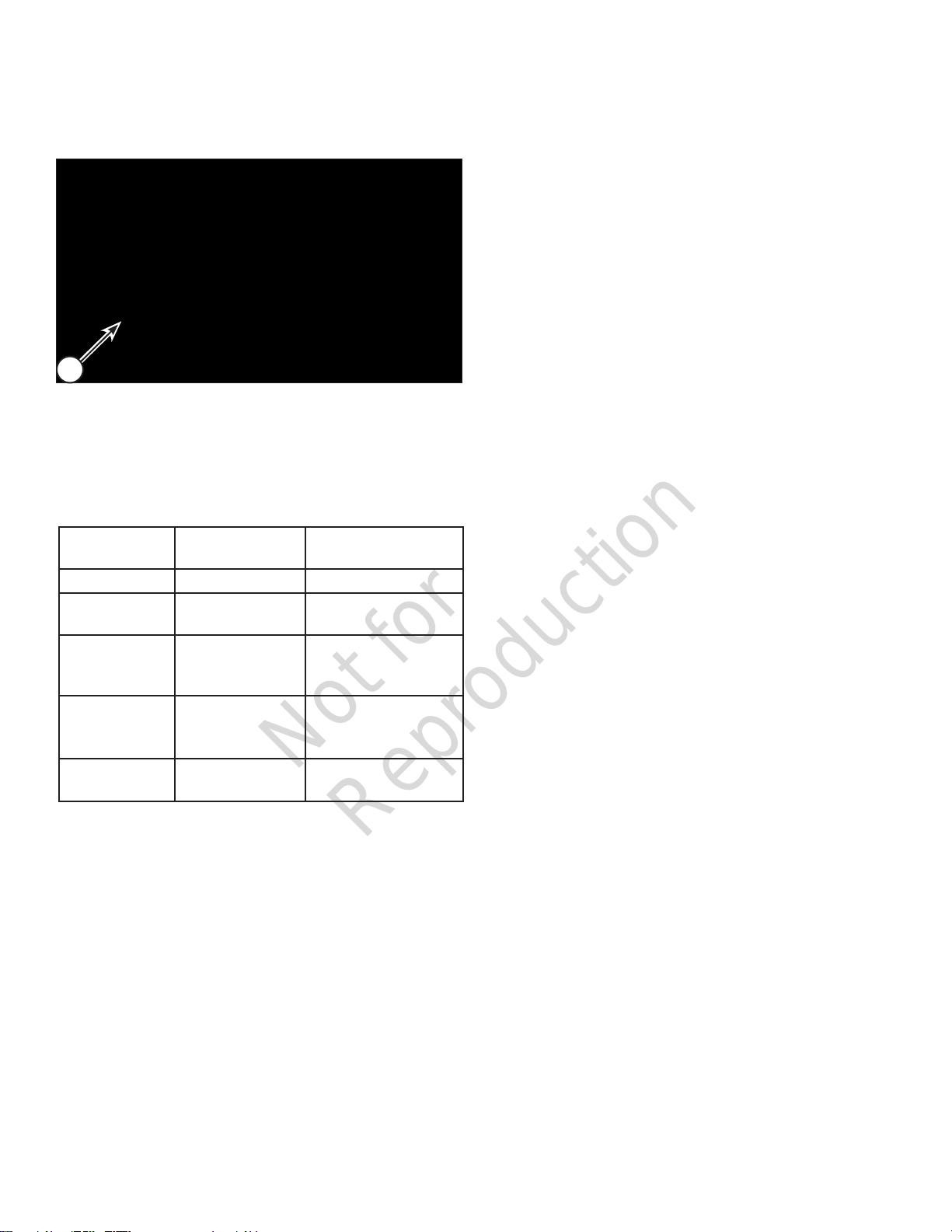
InfoHub LEDS
Status LED lights (C, Figure 9) on the side of the InfoHub module
can provide valuable information about the operation of the
device.
C
Figure 9
Should you need technical assistance, you may need to provide
the LED status information to customer support (1-833-463-
6482).
Under standard configurations, GPS and Communications LED
lights are enabled using the chart below.
LED Condition Green (GPS) Orange
(Communication)
OFF* GPS OFF Modem OFF
Slow Blink
(1x Per Second)
Fast Blink
(4x Per Second)
3 Blinks + 1
Pause
Solid
* Under normal operating conditions, if both GPS &
Communications LEDs are OFF, power to the device has been
lost. The devices are configurable. The modem functionality and
LED status lights can be disabled. In the event the LEDs are not
present when the device is connected to your battery, please
reference www.infohubsp.com or contact technical support to
verify configuration.
Cannot acquire GPS
signal.
Attempting to
acquire GPS
signal.
Not Applicable.
GPS Acquired.
Cannot acquire
communication signal.
Attempting to acquire
communication signal.
Registered, but
no inbound
acknowledgment.
Communication
acquired.
Global Position System (GPS) Capabilities
The lnfoHub system contains Global Position System (GPS)
capabilities. The GPS technology provides geo-location capabilities
which can be used to identify the specific location of a person and/
or the equipment. The GPS technology also enables geo-fencing
capabilities which enable triggering responses when the equipment
enters or leaves a particular area and can be used to identify a
person’s location relative to predetermined boundaries. Certain
federal and state laws, rules and regulations may require you to
notify employees, or other persons who you permit to operate
or use your equipment, that the equipment contains the lnfoHub
system, and that the lnfoHub system collects information about
their physical location and/or the physical location of the equipment.
FCC User Information
THIS EQUIPMENT HAS BEEN TESTED AND FOUND TO COMPLY
WITH THE LIMITS FOR A CLASS B DIGITAL DEVICE, PURSUANT
TO PART 15 OF THE FCC RULES.
THESE LIMITS ARE DESIGNED TO PROVIDE REASONABLE
PROTECTION AGAINST HARMFUL INTERFERENCE IN A
RESIDENTIAL INSTALLATION. THIS EQUIPMENT GENERATES,
USES AND CAN RADIATE RADIO FREQUENCY ENERGY, AND
IF NOT INSTALLED AND USED IN ACCORDANCE WITH THE
INSTRUCTIONS, MAY CAUSE HARMFUL INTERFERENCE TO
RADIO COMMUNICATIONS. HOWEVER, THERE IS NO GUARANTEE
THAT INTERFERENCE WILL NOT OCCUR IN A PARTICULAR
INSTALLATION. IF THIS EQUIPMENT DOES CAUSE HARMFUL
INTERFERENCE TO RADIO OR TELEVISION RECEPTION, WHICH
CAN BE DETERMINED BY TURNING THE EQUIPMENT OFF
AND ON, THE USER IS ENCOURAGED TO TRY TO CORRECT
THE INTERFERENCE BY ONE OR MORE OF THE FOLLOWING
MEASURES:
• REORIENT OR RELOCATE THE RECEIVING ANTENNA.
• INCREASE THE SEPARATION BETWEEN THE EQUIPMENT
AND RECEIVER.
• CONNECT THE EQUIPMENT INTO AN OUTLET ON A CIRCUIT
DIFFERENT FROM THAT TO WHICH THE RECEIVER IS
CONNECTED.
• CONSULT THE DEALER OR AN EXPERIENCED RADIO/TV
TECHNICIAN FOR HELP.
IC User Information
THIS DEVICE COMPLIES WITH INDUSTRY CANADA’S LICENCEEXEMPT RSSS. OPERATION IS SUBJECT TO THE FOLLOWING
TWO CONDITIONS:
• THIS DEVICE MAY NOT CAUSE INTERFERENCE; AND
• THIS DEVICE MUST ACCEPT ANY INTERFERENCE,
INCLUDING INTERFERENCE THAT MAY CAUSE UNDESIRED
OPERATION OF THE DEVICE.
8 BRIGGSandSTRATTON.COM
Page 9
Not for
Reproduction
Suggested infohub™ Installation Locations
Suggested installation locations for each type of standby
generator are shown on the following pages.
Use the illustrations as a guide when mounting the interface
board (E) and cellular unit (G). In some instances, the
interface board needs to be mounted in the area behind the
control panel to enable wires to reach. This will be noted in
such instances.
The following illustrations are representative. Your model of
generator may differ.
For models equipped with this control panel:
Air-Cooled Vertical Standby Generators
Mount (E) behind control panel to allow wires to reach.
E
G
Figure 12
Figure 10
Air-Cooled Horizontal Standby Generators
Mount (E) behind control panel to allow wires to reach.
E
G
Figure 11
Air-Cooled Vertical Standby Generators
E
G
Figure 13
* For liquid cooled horizontal standby generators refer to figure 17 on page 10
9
Page 10
Not for
Reproduction
MENU
ESC
AUTO OFF
MANUAL
For models equipped with this control panel:
Figure 14
Air-Cooled Vertical Standby Generators
Liquid-Cooled Horizontal Standby Generators
E
E
G
Figure 17
G
Figure 15
Air-Cooled Horizontal Standby Generators
E
G
Liquid-Cooled Horizontal Standby Generators
G
E
Figure 16
Figure 18
10 BRIGGSandSTRATTON.COM
Page 11
Not for
Reproduction
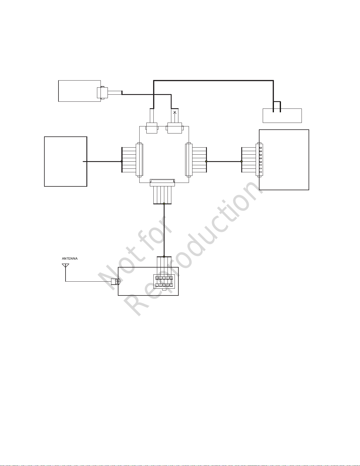
FUSED 240VAC
UTILITY
System Diagram
240 Splitter Harness
J4 J2
J1J5
Relay Wires
COMN.O.
Fault Relay Terminals
From Generator
Cellular Unit
Interface Board
J3
Cellular Unit Harness
Pass-Through
Harness
Generator Control Panel
11
Page 12

Not for
Reproduction
80004543_EN Rev E
BRIGGS & STRATTON PRODUCTS WARRANTY POLICY
LIMITED WARRANTY
Briggs & Stratton warrants that, during the warranty period specified below, it will repair or replace, free of charge, any part that is defective in material or workmanship
or both. Transportation charges on product submitted for repair or replacement under this warranty must be borne by purchaser. This warranty is effective for and is
subject to the time periods and conditions stated below. For warranty service, find the nearest Authorized Service Dealer in our dealer locator map at
BRIGGSandSTRATTON.COM . The purchaser must contact the Authorized Service Dealer, and then make the product available to the Authorized Service Dealer for
inspection and testing.
There are no other express warranties or implied warranties, including those of merchantability, fitness for a particular purpose, or that use of the
product will be available uninterrupted, timely, secure or error free. The warranty is limited to the warranty period listed below, or to the extent permitted
by law. Liability for incidental or consequential damages are excluded to the extent exclusion is permitted by law. Some states or countries do not allow
limitations on how long an implied warranty lasts, and some states or countries do not allow the exclusion or limitation of incidental or consequential damages, so the
above limitation and exclusion may not apply to you. This warranty gives you specific legal rights and you may also have other rights which vary from state to state or
country to country.**
WARRANTY PERIOD
** In Australia - Our goods come with guarantees that cannot be excluded under the Australian Consumer Law. You are entitled to a replacement or refund for a major
failure and for compensation for any other reasonably foreseeable loss or damage. You are also entitled to have the goods repaired or replaced if the goods fail to be
of acceptable quality and the failure does not amount to a major failure. For warranty service, find the nearest Authorized Service Dealer in our dealer locator map at
BRIGGSandSTRATTON.COM, or by calling 1300 274 447, or by emailing or writing to salesenquires@briggsandstratton.com.au, Briggs & Stratton Australia Pty Ltd, 1
Moorebank Avenue, NSW, Australia, 2170.
The warranty period begins on the date of purchase by the first retail or commercial consumer. “Consumer use” means personal residential household use by a retail
consumer “Commercial use” means all other uses, including use for commercial, income producing or rental purposes. Once a product has experienced commercial use, it
shall thereafter be considered as a commercial use product for purposes of this warranty.
To ensure prompt and complete warranty coverage, register your product at the website shown above or at www onlineproductregistration.com, or mail the completed
registration card (if provided.)
Save your proof of purchase receipt. If you do not provide proof of the initial purchase date at the time warranty service is requested, the manufacturing date of the product
will be used to determine the warranty period. Product registration is not required to obtain warranty service on Briggs & Stratton products.
ABOUT YOUR WARRANTY
Warranty service is available only through Briggs & Stratton Authorized Service Dealers. Most warranty repairs are handled routinely, but sometimes requests for warranty
service may not be appropriate. This warranty covers only defects in materials or workmanship. It does not cover damage caused by improper use or abuse, improper
maintenance or repair, or normal wear and tear.
Improper Use and Abuse - The proper, intended use of this product is described in the Operator’s Manual. Using the product in a way not described in the Operator’s
Manual or using the product after it has been damaged will not be covered under this warranty. Warranty coverage will also not be provided if the serial number on the
product has been removed or the product has been altered or modified In any way, or if the product has evidence of abuse such as impact damage or water/chemical
corrosion damage.
Improper Maintenance or Repair - This product must be installed and maintained according to the procedures and schedules provided in the Installation Manual and the
Operator’s Manual, and serviced or repaired using genuine Briggs & Stratton parts or equivalent. Damage caused by improper installation, lack of maintenance or use of
non-original parts is not covered by this warranty.
Normal Wear and Tear - Like most mechanical devices, your unit is subject to wear even when properly maintained. This warranty does not cover repairs when normal
use has exhausted the life of a part or the equipment. Maintenance and wear items such as filters, belts, cutting blades, and brake pads (except engine brake pads) are not
covered by warranty due to wear characteristics alone, unless the cause is due to defects in material or workmanship.
Operating Conditions - Use of the Internet connected product may be inhibited by inability to obtain and maintain a network connection, send or receive GPS, satellite or
wireless connections, electromagnetic interference, environmental or atmospheric conditions, cyber security attacks, or other conditions beyond our control. Respectively
we make no warranty concerning coverage or distance or conditions beyond our control of which inhibits usable signals transmitted and received by our product.
Other Exclusions - This warranty excludes damage due to accident, abuse, modifications, alterations, improper servicing, freezing or chemical deterioration. Attachments
or accessories that were not originally packaged with the product are also excluded. This warranty does not include used, reconditioned, second-hand, or demonstration
equipment or engines. This warranty also excludes failures due to acts of God and other force majeure events beyond the manufacturer’s control.
Item Consumer Use Commercial Use
Accessory/Attachment 12 months 12 months
12 BRIGGSandSTRATTON.COM
Page 13

Not for
Reproduction
Instrucciones de instalación
Monitoreo inalámbrico para Generadores de Energía de Emergencia
Modelo 6517-00
¡La ayuda está muy cerca!
Llame al Departamento de Servicios Técnicos al 1-833-463-6482
De lunes a viernes de 8:00a17:00, horario central
Derecho de autor © Briggs & Stratton Corporation
Milwaukee, WI, EE. UU. Todos los derechos reservados.
¿Preguntas?
80029482USCN
Revisión B
Page 14

Not for
Reproduction
Contenido del kit de monitoreo avanzado
Guarde este documento junto con el manual para el operador del
generador una vez finalizada la instalación.
Contenido del kit de infohub™
•Cables del divisor de 240V (A)
•Cables de la unidad celular (B)
•Cable pasador (C)
•Cable del relé (D)
•Panel de interfaz (E)
•Adaptador para unidad enfriada por líquido (F)
•Unidad de celular (G)
•Antena (H)
•Fijaciones para cable
•Arandela de goma
A B
Elementos necesarios para la instalación del
kit:
•Perforadora con broca de 3/8pulgada
•Paños empapados en alcohol u otra solución de limpieza
•Destornilladores estándares y phillips
•Voltímetro o multímetro
•Cortador de cables/Pelacables
•Herramienta para quitar rebabas
•Producto inhibidor de óxido
C
D
E
HGF
2 BRIGGSandSTRATTON.COM
Page 15

Not for
Reproduction
Seguridad
CONSERVE ESTAS INSTRUCCIONES: esta hoja contiene
instrucciones importantes de seguridad que se deben seguir
durante la instalación del equipo.
Símbolo de alerta de seguridad y palabras de señalización
El símbolo de alerta de seguridad se usa para identificar
información de seguridad sobre riesgos que pueden provocar
lesiones personales. Se utiliza una palabra de señalización
(PELIGRO, ADVERTENCIA o PRECAUCIÓN) junto con el
símbolo de alerta para indicar la probabilidad de una lesión y
su potencial gravedad. Además, se puede usar un símbolo
de peligro para representar el tipo de riesgo.
PELIGRO indica un peligro que, si no se evita, ocasionará
la muerte o lesiones graves.
ADVERTENCIA indica un riesgo que, si no se evita, podría
ocasionar la muerte o lesiones graves.
PRECAUCIÓN indica un peligro que, si no se evita, podría
ocasionar lesiones menores o moderadas.
AVISO indica una acción que podría provocar daños al
producto.
Símbolos de peligro y sus significados
Descarga eléctrica
La instalación de este equipo debe cumplir estrictamente
con la totalidad de los códigos, los estándares y las
normativas vigentes, por lo que solo debe ser llevada a cabo
por un electricista con licencia.
ADVERTENCIA “Este producto puede exponerlo a
sustancias químicas, entre las que se incluyen emisiones
de escape de motor de gasolina, reconocidas por el Estado
de California como causantes de cáncer, y monóxido de
carbono, reconocido por el Estado de California como
causante de defectos de nacimiento u otros problemas
reproductivos. Para obtener más información, visite www.
P65Warnings.ca.gov.”
Piezas giratorias
Arranque automático
ADVERTENCIA
a los trabajadores de la red pública eléctrica, debido a la
alimentación inversa de la energía.
• NO toque cables ni receptáculos sin aislamiento.
• NO use el generador con cables eléctricos que estén
desgastados, raídos, sin aislamiento o dañados de
cualquier otro modo.
• NO manipule el generador ni los cables eléctricos si está
en contacto con agua, descalzo o si sus manos o pies
están mojados.
• Si debe trabajar cerca de una unidad mientras está
funcionando, párese en una superficie seca y aislada para
reducir el peligro de descarga.
• NO permita que personas no calificadas o niños operen o
realicen mantenimiento al generador.
• En caso de un accidente por descarga eléctrica,
corte inmediatamente la fuente de energía eléctrica y
comuníquese con las autoridades locales. Evite el
contacto directo con la víctima.
• A pesar del diseño seguro del generador, si lo opera de
manera imprudente, no realiza el mantenimiento o si es
descuidado, se pueden producir lesiones o la muerte.
• Permanezca alerta en todo momento mientras trabaja
en el equipo. Nunca trabaje en los equipos cuando esté
mental o físicamente fatigado.
• Antes de realizar cualquier tipo de mantenimiento en
el generador, primero desconecte el cable de la batería
que tiene la indicación NEGATIVO, NEG o (-). Cuando
termine, vuelva a conectar este cable al final.
• Después de instalar el sistema, el generador puede
arrancar sin advertencia cada vez que se produzca un
corte de energía. ANTES de trabajar en el equipo y para
evitar posibles lesiones, deje el interruptor del sistema del
generador siempre en posición de apagado APAGADO,
quite el fusible de desconexión del servicio de la caja de
desconexión y quite el fusible de15A.
Los generadores producen una tensión
peligrosa.
Una conexión a tierra defectuosa del generador puede
provocar electrocución.
de la energía eléctrica de la red pública
podría provocar la muerte o lesiones graves
No aislar el generador
PRECAUCIÓN
puede hacer que el motor arranque en cualquier
momento sin advertencia, lo que podría ocasionar
lesiones menores o moderadas.
• Asegúrese de que el fusible de 15A se haya retirado del
panel de control antes de realizarle mantenimiento a la
unidad.
• NO instale este fusible antes de que se haya realizado todo
el cableado y se lo haya inspeccionado.
3
La instalación del fusible de 15A
Page 16

Not for
Reproduction
Instalación
Gracias por adquirir este generador de reserva doméstico. Si
realiza la instalación según estas instrucciones, el dispositivo
de control le proporcionará años de servicio confiable.
Conserve el recibo de compra con esta hoja de instrucciones
y guárdelos junto con los otros manuales del generador una
vez realizada la instalación.
IMPORTANTE: Las ilustraciones incluidas en este
documento son únicamente de referencia y es posible que
no sean representativas de la unidad real a la que se realiza
mantenimiento. La instalación de su unidad será similar.
Antes de comenzar la instalación, consulte las Ubicaciones
sugeridas de instalación de infohub™ en la parte final de
estas instrucciones para identificar su tipo particular de
generador. Las ubicaciones de ensamblado preferidas para
el panel de interfaz (E) y la unidad celular (G) se mostrarán
en estas ilustraciones.
Desconecte la energía eléctrica
Antes de realizar cualquier labor de instalación o
mantenimiento en el generador, siga SIEMPRE los pasos
ADVERTENCIA Peligro de descarga eléctrica. La tensión
proveniente del servicio de energía eléctrica de la
red pública o del generador es peligrosa y podría
provocar la muerte o lesiones graves.
y retire todas las fuentes de tensión de
alimentación y siga todas las instrucciones para
la desconexión de la energía eléctrica antes de realizar
cualquier tipo de trabajo de mantenimiento. Verifique con
un dispositivo de medición que se haya desconectado la
energía eléctrica de la red pública.
siguientes:
1. Coloque el interruptor del sistema del generador en la
posición APAGADO.
2. Coloque el disyuntor del generador en la posición
APAGADO.
3. Retire el fusible de 15A del panel de control.
4. El panel de control del generador recibe tensión del
suministro eléctrico de la red pública. Desconecte
la energía eléctrica antes de realizar mantenimiento en
el panel de control; para esto, retire los fusibles del
interruptor de transferencia.
5. Desconecte el cable negativo de la batería del terminal
negativo de la batería (con la indicación NEGATIVO,
NEG o [-]).
AVISO: Solamente se deben usar los orificios para cables
existentes a fin de llevar los cables de infohub al controlador
del generador. Excepto por el orificio del cable de la antena,
no es necesario perforar otros orificios de acceso.
Desconecte
1. Consulte las Ubicaciones sugeridas de instalación
de infohub™ en el final de estas instrucciones para
determinar la ubicación de ensamblado para la unidad
celular.
2. Con una broca de 3/8pulgadas, perfore un orificio en
la caja cerca de la ubicación deseada para la unidad
celular, de manera que el cable de la antena alcance la
unidad (Figura1). El orificio debe estar cerca del techo
pero no demasiado, a fin de que no cause interferencia
cuando el techo se abra totalmente.
Figura1
3. Después de perforar el orificio, quite las rebabas y
restos de metal de la caja para evitar oxidaciones.
4. Aplique una cantidad pequeña de inhibidor de óxido en
el interior y el exterior de los bordes del orificio, y deje
secar.
Coloque la antena en el techo
1. Busque la arandela de goma que se proporciona con el
kit.
2. Con cuidado, corte un lado hacia el centro de la
arandela de goma.No la corte por la mitad.
3. Cuando el inhibidor de óxido esté seco en el orificio
del cable de la antena, deslice la arandela sobre dicho
cable, pase el cable de la antena por el orificio y calce la
arandela en el orificio.
4A. Coloque la antena magnética en el techo del generador.
4B. En el caso de las unidades con techos de plástico o
aluminio, use la arandela que se proporciona y la cinta
adhesiva.
• Busque una ubicación apropiada en el techo. Esta
ubicación debe estar cerca del orificio del cable de la
antena.
• Quite la película protectora adhesiva roja de la arandela
y presione firmemente en el techo.
• Coloque la antena magnética en la arandela.
Perforar el orificio para el cable de la antena
4 BRIGGSandSTRATTON.COM
Page 17

Not for
Reproduction
5. En el exterior de la caja, haga un bucle con el cable de
la antena y fíjelo con precinto (Figura2) para evitar que
ingrese agua a la unidad.
Figura2
6. Enrute el cable de la antena hacia la ubicación de
montaje deseada de la unidad celular.
J6
Figura4A
2. Quite los tornillos para acceder a la placa del panel de
J6
Desconectar los cables del generador
Verifique que la alimentación eléctrica está desconectada de
la unidad antes de comenzar a trabajar.
1. Quite los tornillos y el frente de la caja de control para
acceder el panel de control. El generador tendrá uno
de dos tipos de paneles (Figura 3A o 3B).
MENU
ESC
AUTO OFF
Figura3A
Figura3B
MANUAL
Figura4B
control en la parte de atrás del panel. El generador
tendrá uno de dos tipos de paneles (Figura 4A o 4B).
3. Desconecte los cables del generador (conector de
8cables) del conector J6 de la placa de control.
D
C
E
B
A
Figura 5
Identificar las conexiones del panel interfaz
Ubique el panel interfaz suministrado con el kit. Antes de
continuar, revise y comprenda la designación de conectores
del panel interfaz (Figura5).
A - Conector del cable del generador del panel de control
B - Conector del cable del relé de fallos
C - Conector del cable del divisor de 240V
D - Conector del cable pasador
E - Conector de los cables de la unidad celular
5
Page 18

Not for
Reproduction
Instalar cable del relé
1. Ubique el cable del relé que se suministra con el kit.
Determine la longitud del cable necesario y corte dos
piezas. Pele los cuatro extremos antes de la instalación.
2. Inserte un extremo de cada cable en los terminales N.O.
y COM en el enchufe de conector de 10pines o el bloque
de terminales. Inserte el otro extremo de cada uno de los
cables en el panel interfaz presionando las lengüetas en
el conector del relé (B, Figura5). La polaridad no tiene
importancia.
4. Lleve el otro extremo del cable hasta el panel interfaz y
conéctelo al conector del cable del divisor de 240V (C,
Figura5).
Instalar el cable pasador
1. Ubique el cable pasador que se suministra con el kit.
2. Conecte el cable pasador en el panel de control, luego
llévelo al panel interfaz y conéctelo en el conector del
cable pasador (D, Figura5).
Instalar el cable de la unidad celular
1. Ubique el cable de la unidad celular que se suministra
con el kit.
2. Conecte el cable de la unidad celular en la unidad celular,
luego llévelo hasta el panel interfaz y conéctelo al
conector del cable de la unidad celular (E, Figura5).
D
Figura6
Instale los cables del divisor de 240V (unidades
enfriadas por aire)
1. Ubique los cables del divisor de 240V que se suministra
con el kit.
2. Conecte el cable del divisor de 240V en el conector del
calentador de la batería (flecha, Figura6).
3. Lleve el otro extremo del cable hasta el panel interfaz y
conéctelo al conector del cable del divisor de 240V (C,
Figura5).
Instale los cables del divisor de 240V
(unidades enfriadas por líquido)
1. Ubique el cable del divisor de 240V y el cable del
adaptador enfriado por líquido que se suministran con el
kit.
2. Conecte el cable del divisor de 240V al cable del
adaptador.
3. En el bloque de fusibles dentro del generador, conecte
cada cable del adaptador en los terminales espada debajo
de cada fusible (flecha, Figura7).
C
E
B
A
Figura8
Verificar la instalación
1. Compare sus conexiones con la Figura8 para confirmar
la instalación adecuada de los cables.
A - Conector del cable del generador del panel de control
B - Conector del cable del relé de fallos
C - Conector del cable del divisor de 240V
D - Conector del cable pasador
E - Conector de los cables de la unidad celular
2. Asegúrese de que todos estos conectores están fijados
en su lugar.
3. Enrute el cable del generador en el panel de control hacia
el panel interfaz y conéctelo al conector del cable del
generador (A, Figura5).
Figura7
6 BRIGGSandSTRATTON.COM
Page 19

Not for
Reproduction
Panel de interfaz de montaje
Limpie la superficie de montaje para el panel interfaz con
un paño embebido en alcohol u otra solución de limpieza.
Retire la cubierta de la tira adhesiva que se encuentra en la
parte posterior del panel, luego presiónelo con firmeza en
su lugar. Consulte las páginas 9y10para ver la ubicación
recomendada.
Montar la unidad celular
Limpie la superficie de montaje para la unidad celular con
un paño embebido en alcohol u otra solución de limpieza.
Retire la cubierta de la tira adhesiva que se encuentra
en la parte posterior de la unidad, luego presiónela con
firmeza en su lugar. Conecte el cable de la antena en este
momento. Consulte las páginas 9y10para ver la ubicación
recomendada.
Cerrar el generador e instalar los fusibles
1. Use los fijadores de cable que se suministran para
organizar los cables y fijar el exceso de cable.
2. Vuelva a instalar el panel de control con los tornillos.
3. Vuelva a instalar el frente de la caja de control con los
tornillos.
4. Conecte el cable de batería negro al terminal negativo
de la batería (indicado comoNEGATIVO, NEG, o [-]).
5. Vuelva a instalar los fusibles en la llave de
transferencia.
6. Vuelva a instalar el fusible de 15A en el panel de
control.
7. Coloque el disyuntor del generador en la posición
ENCENDIDO.
8. Ponga el interruptor del sistema generador en
AUTOMÁTICO.
Registro y activación
El acceso al portal de usuario de InfoHub requiere
adquisición de una suscripción. Debe registrarse y activar
el sistema de InfoHub en línea en www.infohubsp.com. Las
guías de usuario y los videos instructivos están disponibles
en este sitio.
Deberá leer y cumplir con el Contrato de servicio de
suscripción de InfoHub antes de activar la suscripción
mensual y los Términos de uso y la Política de privacidad
antes del acceder al portal InfoHub. Visite www.
briggsinfohub.com para obtener una vista previa de estas
políticas.
Para obtener soporte para el registro y la activación, llame al
equipo de soporte de InfoHub al 1-833-463-6482.
Antes de la instalación, grabe el módulo ESN y P/N en los
espacios a continuación. Esta información es necesaria para
asignar correctamente el módulo al equipo del portal del
usuario.
InfoHub
ESN:
P/N:
Equipo
Marca:
Tipo de equipo:
Número de modelo:
Número de serie
Requerimientos mínimos del sistema Portal de usuario
Navegadores que soporta y versiones
• Chrome - Versión 59.0+
• Firefox - Versión 54.0+
• Safari - Versión 10.0+
• IE - Versión 11.0+
• Edge - Versión 15.0+
Resolución de pantalla mínima
• 1280 x 720
Requerimientos de computación
• Intel® Core™ i3 o equivalente
• 4GB de RAM
• Acceso a Internet
Ajustes especiales
• Las ventanas emergentes son necesarias para los
informes.
• La URL utilizada para la herramienta iFrame debe
soportar iFrames.
7
Page 20

Not for
Reproduction
Luces LED de InfoHub
Las luces LED de estado (C, Figura9) que figuran al costado
del módulo de InfoHub pueden brindar información sobre la
operación del dispositivo.
C
Figura 9
En caso de necesitar asistencia técnica, tendrá que proporcionar
información de la LED de estado a soporte al cliente (1-833-463-
6482).
Bajo configuración estándar, el GPS y las luces LED de
comunicaciones están activadas utilizando el cuadro a
continuación.
Condición
LED
APAGADO* GPS APAGADO Módem APAGADO
Parpadeo lento
(1vez por
segundo)
Parpadeo rápido
(4veces por
segundo)
3parpadeos
+1pausa
Sólido
* Bajo condiciones operativas normales, si las luces LED de GPS
y comunicaciones están APAGADAS, se perdió la electricidad del
dispositivo. Los dispositivos son configurables. La funcionalidad
del módem y las luces LED de estado se pueden desactivar. En
caso de que las LED no estén presentes cuando el dispositivo
se conecta a la batería, consulte en www.infohubsp.com o
comuníquese con soporte técnico para verificar la configuración.
Verde (GPS) Naranja
(Comunicación)
No puede adquirir
señal de GPS.
Intentando adquirir
señal de GPS.
No aplicable.
GPS adquirido.
No puede adquirir
señal de comunicación.
Intentando adquirir
señal de comunicación.
Registrado, pero sin
reconocimiento de
entrada.
Comunicación
adquirida.
Capacidades de sistema de posición global (GPS)
El sistema InfoHub contiene capacidades de sistema de posición
global (GPS). La tecnología de GPS brinda capacidades de
geoubicación que pueden usarse para identificar la ubicación
específica de una persona y/o del equipo. La tecnología de
GPS también activa capacidades de geovalla que permiten
el desencadenamiento de respuestas cuando el equipo
ingresa o sale de un área en particular y pueden usarse para
identificar la ubicación de una persona relacionada con límites
predeterminados. Algunas leyes, normas y reglamentaciones
federales y estatales pueden requerirle que notifique a los
empleados o a otras personas a las que le permita operar o usar
su equipo que el equipo contiene el sistema InfoHub, y que este
sistema recopila información sobre su ubicación física y/o la
ubicación física del equipo.
Información de usuario FCC
ESTE EQUIPO FUE PROBADO Y SE CONFIRMÓ QUE CUMPLE
CON LOS LÍMITES PARA UN DISPOSITIVO DIGITAL DE CLASE B,
EN CUMPLIMIENTO CON LA PARTE15 DE LAS NORMAS FCC.
ESTOS LÍMITES ESTÁN DISEÑADOS PARA BRINDAR
PROTECCIÓN RAZONABLE CONTRA INTERFERENCIAS
DAÑINAS EN UNA INSTALACIÓN RESIDENCIAL. ESTE
EQUIPO GENERA, USA Y PUEDE IRRADIAR ENERGÍA DE
RADIOFRECUENCIA Y, SI NO SE INSTALA Y USA CONFORME
A LAS INSTRUCCIONES, PUEDE CAUSAR INTERFERENCIA
DAÑINA A LAS COMUNICACIONES DE RADIO. SIN EMBARGO,
NO HAY GARANTÍA DE QUE NO HABRÁINTERFERENCIAS
EN UNA INSTALACIÓN EN PARTICULAR. SI ESTE EQUIPO
CAUSA INTERFERENCIA DAÑINA A RECEPCIONES DE RADIO
O TELEVISIÓN, QUE PUEDE DETERMINARSE ENCENDIENDO Y
APAGANDO EL EQUIPO, ALENTAMOS AL USUARIO A INTENTAR
CORREGIR LA INTERFERENCIA SIGUIENDO UNA O MÁS DE LAS
SIGUIENTES MEDIDAS:
• VUELVA A ORIENTAR O UBICAR LA ANTENA DE RECEPCIÓN.
• AUMENTE LA SEPARACIÓN ENTRE EL EQUIPO Y EL
RECEPTOR.
• CONECTE EL EQUIPO EN UN TOMACORRIENTE DE UN
CIRCUITO DISTINTO AL QUE SE ENCUENTRA CONECTADO
EL RECEPTOR.
• CONSULTE CON EL VENDEDOR O CON UN TÉCNICO DE
RADIO/TV CON EXPERIENCIA PARA OBTENER AYUDA.
Información de usuario de IC
ESTE DISPOSITIVO CUMPLE CON LAS RSS EXENTAS DE
LICENCIA DE INDUSTRY CANADA. LA OPERACIÓN ESTÁ SUJETA
A LAS SIGUIENTES DOS CONDICIONES:
• ESTE DISPOSITIVO NO PUEDE PROVOCAR INTERFERENCIA;
Y
• ESTE DISPOSITIVO DEBE ACEPTAR CUALQUIER
INTERFERENCIA, INCLUSIVE LA INTERFERENCIA QUE
PUEDA CAUSAR UN FUNCIONAMIENTO NO DESEADO.
8 BRIGGSandSTRATTON.COM
Page 21

Not for
Reproduction
Ubicaciones sugeridas de instalación de ™
Las ubicaciones de instalación sugeridas para cada tipo de
generador standby se muestran en las siguientes páginas.
Use las ilustraciones como guía cuando monte el panel
interfaz (E) y la unidad celular (G). En algunos casos, el
panel interfaz debe montarse en la zona detrás del panel de
control para permitir que los cables alcancen su punto de
conexión. En esos casos, se indicará esta situación.
Las siguientes ilustraciones son representativas. Su modelo
de generador puede ser diferente.
Para modelos equipados con este panel de
control:
Generadores standby verticales enfriados por aire
Debe montarlo (E) detrás del panel de control para permitir
que los cables alcancen su punto de conexión.
E
G
Figura12
Figura10
Generadores standby horizontales enfriados por
aire
Debe montarlo (E) detrás del panel de control para permitir
que los cables alcancen su punto de conexión.
E
G
Figura11
Generadores standby verticales enfriados por aire
E
G
Figura13
* Para los generadores standby horizontales enfriados por líquido consulte la figura17 en la
página10
9
Page 22

Not for
Reproduction
MENU
ESC
AUTO OFF
MANUAL
Para modelos equipados con este panel de
control:
Figura14
Generadores standby verticales enfriados por aire
Generadores standby horizontales enfriados por
líquido
E
E
G
Figura 17
G
Figura 15
Generadores standby horizontales enfriados por
aire
E
G
Generadores standby horizontales enfriados por
líquido
G
E
Figura 16
Figura 18
10 BRIGGSandSTRATTON.COM
Page 23

Not for
Reproduction
FUSED 240VAC
UTILITY
System Diagram
240 Splitter Harness
J4 J2
J1J5
Relay Wires
COMN.O.
Fault Relay Terminals
From Generator
Cellular Unit
Interface Board
J3
Cellular Unit Harness
Pass-Through
Harness
Generator Control Panel
11
Page 24

Not for
Reproduction
80004543_EN Rev E
BRIGGS & STRATTON PRODUCTS WARRANTY POLICY
LIMITED WARRANTY
Briggs & Stratton warrants that, during the warranty period specified below, it will repair or replace, free of charge, any part that is defective in material or workmanship
or both. Transportation charges on product submitted for repair or replacement under this warranty must be borne by purchaser. This warranty is effective for and is
subject to the time periods and conditions stated below. For warranty service, find the nearest Authorized Service Dealer in our dealer locator map at
BRIGGSandSTRATTON.COM . The purchaser must contact the Authorized Service Dealer, and then make the product available to the Authorized Service Dealer for
inspection and testing.
There are no other express warranties or implied warranties, including those of merchantability, fitness for a particular purpose, or that use of the
product will be available uninterrupted, timely, secure or error free. The warranty is limited to the warranty period listed below, or to the extent permitted
by law. Liability for incidental or consequential damages are excluded to the extent exclusion is permitted by law. Some states or countries do not allow
limitations on how long an implied warranty lasts, and some states or countries do not allow the exclusion or limitation of incidental or consequential damages, so the
above limitation and exclusion may not apply to you. This warranty gives you specific legal rights and you may also have other rights which vary from state to state or
country to country.**
WARRANTY PERIOD
** In Australia - Our goods come with guarantees that cannot be excluded under the Australian Consumer Law. You are entitled to a replacement or refund for a major
failure and for compensation for any other reasonably foreseeable loss or damage. You are also entitled to have the goods repaired or replaced if the goods fail to be
of acceptable quality and the failure does not amount to a major failure. For warranty service, find the nearest Authorized Service Dealer in our dealer locator map at
BRIGGSandSTRATTON.COM, or by calling 1300 274 447, or by emailing or writing to salesenquires@briggsandstratton.com.au, Briggs & Stratton Australia Pty Ltd, 1
Moorebank Avenue, NSW, Australia, 2170.
The warranty period begins on the date of purchase by the first retail or commercial consumer. “Consumer use” means personal residential household use by a retail
consumer “Commercial use” means all other uses, including use for commercial, income producing or rental purposes. Once a product has experienced commercial use, it
shall thereafter be considered as a commercial use product for purposes of this warranty.
To ensure prompt and complete warranty coverage, register your product at the website shown above or at www onlineproductregistration.com, or mail the completed
registration card (if provided.)
Save your proof of purchase receipt. If you do not provide proof of the initial purchase date at the time warranty service is requested, the manufacturing date of the product
will be used to determine the warranty period. Product registration is not required to obtain warranty service on Briggs & Stratton products.
ABOUT YOUR WARRANTY
Warranty service is available only through Briggs & Stratton Authorized Service Dealers. Most warranty repairs are handled routinely, but sometimes requests for warranty
service may not be appropriate. This warranty covers only defects in materials or workmanship. It does not cover damage caused by improper use or abuse, improper
maintenance or repair, or normal wear and tear.
Improper Use and Abuse - The proper, intended use of this product is described in the Operator’s Manual. Using the product in a way not described in the Operator’s
Manual or using the product after it has been damaged will not be covered under this warranty. Warranty coverage will also not be provided if the serial number on the
product has been removed or the product has been altered or modified In any way, or if the product has evidence of abuse such as impact damage or water/chemical
corrosion damage.
Improper Maintenance or Repair - This product must be installed and maintained according to the procedures and schedules provided in the Installation Manual and the
Operator’s Manual, and serviced or repaired using genuine Briggs & Stratton parts or equivalent. Damage caused by improper installation, lack of maintenance or use of
non-original parts is not covered by this warranty.
Normal Wear and Tear - Like most mechanical devices, your unit is subject to wear even when properly maintained. This warranty does not cover repairs when normal
use has exhausted the life of a part or the equipment. Maintenance and wear items such as filters, belts, cutting blades, and brake pads (except engine brake pads) are not
covered by warranty due to wear characteristics alone, unless the cause is due to defects in material or workmanship.
Operating Conditions - Use of the Internet connected product may be inhibited by inability to obtain and maintain a network connection, send or receive GPS, satellite or
wireless connections, electromagnetic interference, environmental or atmospheric conditions, cyber security attacks, or other conditions beyond our control. Respectively
we make no warranty concerning coverage or distance or conditions beyond our control of which inhibits usable signals transmitted and received by our product.
Other Exclusions - This warranty excludes damage due to accident, abuse, modifications, alterations, improper servicing, freezing or chemical deterioration. Attachments
or accessories that were not originally packaged with the product are also excluded. This warranty does not include used, reconditioned, second-hand, or demonstration
equipment or engines. This warranty also excludes failures due to acts of God and other force majeure events beyond the manufacturer’s control.
Item Consumer Use Commercial Use
Accessory/Attachment 12 months 12 months
12 BRIGGSandSTRATTON.COM
Page 25

Not for
Reproduction
Instructions d’installation
Moniteur de surveillance sans fil pour groupe électrogène fixe
Modèle 6517-00
Téléphonez au Service technique au 1-833-463-6482
du lundi au vendredi de 8 h à 17 h, heure normale du Centre
Copyright © Briggs & Stratton Corporation
Milwaukee, WI, É.-U. Tous droits réservés.
Des questions?
De l’aide au bout des doigts!
80029482USCN
Révision B
Page 26

Not for
Reproduction
Contenu de la trousse du dispositif avancé de surveillance
Gardez ce document avec le manuel d’utilisation de la génératrice
une fois l’installation terminée.
Contenu de la trousse infoHub™:
•Faisceau de séparation de 240V (A)
•Faisceau de câbles d’appareil cellulaire (B)
•Faisceau de câbles de passage (C)
•Câble de relais (D)
•Carte d’interface (E)
•Adaptateur pour appareil refroidi par liquide (F)
•Appareil cellulaire (G)
•Antenne (H)
•Attaches à fils
•Œillet en caoutchouc
A B
Articles nécessaires pour l’installation de la
trousse:
•Perceuse avec une mèche de 3/8po
•Tampon imbibé d’alcool ou autre solution de nettoyage
•Tournevis à pointes plate et cruciforme
•Voltmètre/multimètre
•Coupe-fils/dénudeur de fils
•Outil d’ébavurage
•Inhibiteur de rouille
C
D
E
HGF
2 BRIGGSandSTRATTON.COM
Page 27

Not for
Reproduction
Sécurité
CONSERVEZ CES INSTRUCTIONS – Cette feuille d’installation
contient des instructions importantes qu’il faut suivre durant
l’installation de l’équipement.
Symbole d’alerte de sécurité et mots de signal
Le symbole d’alerte de sécurité est utilisé pour identifier
l’information de sécurité à propos des dangers pouvant
causer des blessures. Un mot-indicateur (DANGER,
AVERTISSEMENT ou MISE EN GARDE) est utilisé avec le
symbole d’alerte pour indiquer la probabilité et la gravité
potentielle des blessures. En plus, un symbole de danger
peut être utilisé pour représenter le type de danger.
DANGER indique un danger qui, si non évité, provoquera
la mort ou des blessures graves.
AVERTISSEMENT indique un danger qui, si non évité, peut
provoquer la mort ou des blessures graves.
ATTENTION indique un danger qui, si non évité, peut
causer une blessure mineure ou modérée.
AVIS indique une situation qui pourrait causer des
dommages au produit.
Renseignements et symboles de danger
Décharge
électrique
Seuls des électriciens qualifiés et licenciés devraient tenter
l’installation de cet équipement, qui doit être strictement
conforme aux codes, normes et règlements applicables.
AVERTISSEMENT «Ce produit peut vous exposer à des
agents chimiques, y compris aux gaz d’échappements des
moteurs à essence, connus dans l’État de la Californie pour
causer le cancer, ainsi que le monoxyde de carbone, connu
dans l’État de la Californie pour causer des malformations
congénitales ou des dommages au système reproducteur.
Pour obtenir de plus amples renseignements, visitez le
www.P65Warnings.ca.gov.»
MISE EN GARDE
peut provoquer un démarrage du moteur en
tout temps, sans avertissement, et entraîner des
blessures mineures à modérées.
Pièces rotatives
L’installation d’un fusible de 15A
Démarrage
automatique
AVERTISSEMENT
dangereuse.
Si la génératrice n'est pas mise à la terre comme il
se doit, il y a risque d’électrocution.
la génératrice de la source d’alimentation en
électricité peut causer des blessures graves
ou même le décès d’employés du service de distribution
électrique, à la suite de la rétroaction de l’énergie électrique.
• NE PAS toucher aux fils ou à des prises dénudées.
• NE PAS utiliser la génératrice avec des rallonges
électriques usées, effilochées, dénudées ou autrement
endommagées.
• NE PAS manipuler la génératrice ou les cordons
électriques les pieds dans l’eau ou les pieds nus ou
lorsque les mains ou les pieds sont mouillés.
• Si vous devez travailler aux environs d’une unité alors
qu’elle est en marche, placez-vous sur une surface sèche
isolée afin de réduire les risques de décharge électrique.
• NE PAS laisser les personnes non qualifiées ou les
enfants opérer ou entretenir la génératrice.
• En cas d’accident causé par une décharge électrique,
procéder immédiatement à la mise hors tension de
l’alimentation électrique et communiquer avec les
autorités locales. Évitez tout contact direct avec la
victime.
• En dépit de la conception sécuritaire de la génératrice, le
fait d’opérer l’équipement de façon imprudente, de ne pas
l’entretenir ou d’être négligent peut causer des blessures
ou la mort.
• Demeurez alerte en tout temps lorsque vous travaillez sur
cet équipement. Ne travaillez jamais sur l’équipement si
vous êtes fatigué physiquement ou mentalement.
• Avant de procéder à tout entretien sur la génératrice,
débranchez tout d’abord le câble de batterie identifié
par NÉGATIF, NEG ou (-). Rebrancher le câble en tout
dernier, après avoir terminé.
• Une fois que votre système est installé, la génératrice
peut se lancer et démarrer sans avertissement lorsque
survient une panne électrique. AVANT de travailler sur
l’équipement, pour prévenir des blessures potentielles,
réglez toujours l’interrupteur de système de la génératrice
à la position ARRÊT, retirez le fusible de déconnexion de
l’alimentation de service du boîtier de déconnexion ET
enlevez le fusible de 15A.
La génératrice produit une tension
Sans isolation,
• Prenez note que le fusible de 15A a été retiré du tableau
de commande préalablement à l’entretien.
• N’INSTALLEZ PAS ce fusible tant que le câblage n’a pas
été dûment inspecté.
3
Page 28

Not for
Reproduction
Installation
Merci d’avoir acheté cet accessoire de secours pour la maison.
Lorsque installé conformément aux directives qui suivent,
vous pourrez compter sur ce dispositif de surveillance durant
des années. Conservez votre preuve d’achat avec ce feuillet
d’instructions et le manuel d’utilisation de votre génératrice
après l’installation.
IMPORTANT: Les illustrations présentées dans ce document
ne sont qu’à titre de référence et peuvent ne pas représenter
l’appareil faisant l’objet de l’entretien. Votre installation sera
toutefois semblable.
Avant de commencer l’installation, reportez-vous aux
emplacements d’installation suggérés pour le infohub™
à la fin de ces instructions afin d’identifier votre type de
génératrice. Les emplacements de montage préférés pour la
carte d’interface (E) et l’appareil cellulaire (G) seront indiqués
sur les illustrations.
Débranchement de l’alimentation
AVERTISSEMENT Risque de chocs électriques. Une tension
dangereuse du service public ou d’une génératrice
pourrait causer la mort ou des blessures graves.
Retirez toutes les sources d’alimentation de
tension et suivez toutes les instructions de
débranchement électrique avant d’effectuer toute
tâche d’entretien. Vérifiez à l’aide d’un appareil de mesure
que l’alimentation a été débranchée.
Avant de procéder à l’entretien de la génératrice, suivez
TOUJOURS les étapes suivantes:
1. Placez l’interrupteur de la génératrice en position ARRÊT.
2. Réglez le disjoncteur principal de la génératrice à la
position ARRÊT.
3. Retirer le fusible de 15A du tableau de commande.
4. De la tension de service est présente au tableau de
commande de la génératrice. Retirez les fusibles du
commutateur de transfert pour déconnecter l’alimentation
avant d’effectuer l’entretien du tableau de commande.
5. Débranchez le câble négatif de la batterie de la borne
négative de la batterie marquée NEGATIF, NEG ou (-).
AVIS: Seuls les trous de faisceaux en place doivent être
utilisés pour acheminer le faisceau du infohub au contrôleur
de génératrice. À l’exception du trou du câble de l’antenne, il
n’est pas nécessaire de percer d’autres trous d’accès.
Perçage de trou pour le câble de l’antenne
1. Reportez-vous aux emplacements d’installation
suggérées pour le infohub™ à la fin de ces instructions
pour déterminer l’emplacement de montage de l’appareil
cellulaire.
2. En utilisant une mèche de 3/8po, percez un trou dans
le boîtier près de l’emplacement prévu pour l’appareil
cellulaire de sorte que le câble de l’antenne atteigne
l’appareil (Figure1). L’ouverture doit être placée près
du toit, mais pas trop près en raison des interférences
produites lorsque le toit est complètement ouvert.
Figure 1
3. Après avoir percé le trou, retirez les ébarbures et les
copeaux de métal du boîtier pour prévenir la formation de
rouille.
4. Appliquez une petite quantité d’inhibiteur de rouille à
l’intérieur et à l’extérieur des rebords des trous et laissez
sécher.
Montage de l’antenne au toit
1. Localisez l’œillet de caoutchouc fourni dans la trousse.
2. Coupez délicatement d’un côté vers le centre de l’œillet en
caoutchouc. Ne pas couper en deux.
3. Lorsque l’inhibiteur de rouille est sec dans le trou du
câble de l’antenne, glissez l’œillet en caoutchouc sur le
câble de l’antenne, passez le câble de l’antenne par le trou
et placez l’œillet en caoutchouc dans le trou.
4A. Installez l’antenne magnétique sur le toit de la
génératrice.
4B. Pour les appareils avec toit en plastique ou en aluminium,
utilisez la rondelle et l’adhésif fournis.
• Trouvez l’emplacement approprié pour le toit. Cet
emplacement doit être près de l’ouverture pour le câble
de l’antenne.
• Retirez la pellicule de protection adhésive rouge de la
rondelle et appuyez fermement pour fixer le toit.
• Placez l’antenne magnétique sur la rondelle.
4 BRIGGSandSTRATTON.COM
Page 29

Not for
Reproduction
5. À l’extérieur du boîtier, faites une boucle et fixez le
câble de l’antenne avec une attache (Figure2) pour
aider à empêcher l’eau de pénétrer dans l’unité.
Figure 2
6. Faites passer le câble de l’antenne vers l’emplacement
de montage prévu de l’appareil cellulaire.
J6
Figure 4A
J6
Débranchez le faisceau de câbles de la
génératrice
Vérifiez si l’alimentation est déconnectée de l’appareil avant
de procéder.
1. Retirez les vis et l’avant du boîtier de commande pour
accéder au tableau de commande. La génératrice est
MENU
ESC
AUTO OFF
Figure 3A
équipée d’un de deux tableaux (Figure 3A ou 3B).
Figure 3B
MANUAL
Figure 4B
2. Retirez les vis pour accéder au tableau de commande
à l’arrière du panneau. La génératrice est équipée d’un
de deux tableaux de commande (Figure 4A or 4B).
3. Débranchez le faisceau de câbles de la génératrice
(connecteur à 8 fils) à partir du connecteur du tableau
de commande J6.
D
C
E
B
A
Figure 5
Identification des connexions de la carte
d’interface
Localisez la carte d’interface fournie dans la trousse. Avant
de commencer, veuillez lire et comprendre les assignations
des connecteurs de la carte d’interface ci-dessous (Figure5).
A - Faisceau de câbles du tableau de commande à la génératrice
B - Connecteur de relais de défaillance
C - Connecteur du faisceau de séparation de 240V
D - Connecteur de faisceau de passage
E - Connecteur de faisceau de câbles d’appareil cellulaire
5
Page 30

Not for
Reproduction
Installez un câble de relais
1. Localisez le câble de relais fourni dans la trousse.
Déterminez la longueur de fil nécessaire et coupez
deux morceaux. Dénudez les quatre extrémités avant
l’installation.
2. Insérez une extrémité de chaque fil dans les bornes
N.O. et COM dans la fiche du connecteur à 10 broches
ou au bloc de raccordement. Insérez l’autre extrémité
de chaque fil dans la carte d’interface en appuyant sur
les languettes du connecteur de relais (B, Figure5). La
polarité n’a aucune importance.
2. Connectez le faisceau de séparation de 240V au faisceau
de l’adaptateur.
3. Dans la boîte à fusibles à l’intérieur de la génératrice,
connectez chacun des fils du faisceau de l’adaptateur aux
bornes à fourche sous chaque fusible (flèche, Figure7).
4. Faites passer l’autre extrémité du faisceau jusqu’à la carte
d’interface et connectez-la au connecteur de faisceau de
séparation de 240V (C, Figure5).
Installation du faisceau de passage
1. Prenez le faisceau de passage qui se trouve dans la
trousse.
2. Connectez le faisceau de passage au tableau de
commande, puis acheminez-le jusqu’à la carte d’interface
et connectez-le au connecteur de faisceau de passage (D,
Figure5).
Installation du faisceau de l’appareil cellulaire
1. Prenez le faisceau de l’appareil cellulaire qui se trouve
dans la trousse.
D
Figure 6
Installez un harnais de séparation de 240V
(appareils refroidis à l’air)
1. Prenez le faisceau de séparation de 240V qui se trouve dans
la trousse.
2. Branchez le faisceau de séparation de 240V au
connecteur du chauffe-batterie (flèche, Figure6).
3. Faites passer l’autre extrémité du faisceau jusqu’à la carte
d’interface et connectez-la au connecteur de faisceau de
séparation de 240V (C, Figure5).
Figure 7
Installez un faisceau de séparation de 240V
(appareils refroidis au liquide)
1. Prenez le faisceau de séparation de 240V et le faisceau de
l’adaptateur refroidi par liquide qui se trouvent dans la
trousse.
C
E
B
A
Figure 8
2. Connectez le faisceau de l’appareil cellulaire à l’appareil
cellulaire, puis acheminez-le jusqu’à la carte d’interface
et connectez-le au connecteur de faisceau de l’appareil
cellulaire (E, Figure5).
Vérification de l’installation
1. Comparez vos connexions à la Figure 8 pour confirmer
l’installation appropriée des faisceaux.
A - Faisceau de câbles du tableau de commande à la
génératrice
B - Connecteur de relais de défaillance
C - Connecteur du faisceau de séparation de 240V
D - Connecteur de faisceau de passage
E - Connecteur de faisceau de câbles d’appareil cellulaire
2. Assurez-vous que tous ces connecteurs sont solidement
en place.
3. Faites passer le faisceau de câbles de la génératrice
du tableau de commande jusqu’à la carte d’interface et
connectez-le au connecteur de faisceau de la génératrice
(A, Figure 5).
6 BRIGGSandSTRATTON.COM
Page 31

Not for
Reproduction
Installation de la carte d'interface
Préparez la surface de montage de la carte d’interface en la
nettoyant à l’aide d’un tampon imbibé d’alcool ou d’une autre
solution de nettoyage. Enlevez la pellicule protectrice de la
bande adhésive au dos de la carte, puis appuyez fermement
pour fixer la carte. Reportez-vous aux pages 9 et 10 au sujet
de l’emplacement recommandé.
Installation de l’appareil cellulaire
Nettoyez la surface de montage pour l’appareil cellulaire
avec un tampon imbibé d’alcool ou une autre solution de
nettoyage. Enlevez la pellicule protectrice de la bande
adhésive au dos de la carte, puis appuyez fermement pour
fixer l’unité. Connectez le câble de l’antenne à ce moment.
Reportez-vous aux pages 9 et 10 au sujet de l’emplacement
recommandé.
Inscription et activation
L’accès au portail d’utilisateur InfoHub nécessite l’achat
d’un abonnement. Vous devez inscrire et activer le système
InfoHub au www.infohubsp.com. Des guides d’utilisation et
des vidéos éducatives sont offerts sur ce site.
Vous devrez lire et accepter le contrat de service de
l’abonnement à InfoHub avant l’activation de l’abonnement
mensuel, ainsi que les conditions générales d’utilisation et la
politique de confidentialité avant l’accès au portail InfoHub.
Visitez le www.briggsinfohub.com pour consulter ces
politiques.
Pour obtenir de l’aide relative à l’inscription et à l’activation,
appelez l’équipe de soutien à la clientèle d’InfoHub au 1-833463-6482.
Avant l’installation, inscrivez le ESN et le P/N du module
dans les espaces ci-dessous. Ces renseignements sont
requis pour correctement attribuer le module à l’équipement
dans le portail d’utilisateur.
InfoHub
Fermez la génératrice et installez les fusibles
1. Utilisez les attaches fournies pour organiser les
faisceaux de câbles et pour fixer la longueur excessive
de câbles.
2. Replacez le tableau de commande et fixez-le avec des
vis.
3. Replacez le boîtier de commande à l’avant et fixez-le
avec des vis.
4.Branchez le câble négatif de la batterie à la borne négative
de la batterie marquée NEGATIF, NEG, ou (-).
5. Replacez les fusibles dans le commutateur de transfert.
6. Replacez le fusible de 15A dans le tableau de
commande.
7. Réglez le disjoncteur de la génératrice en MARCHE.
8. Réglez le commutateur de la génératrice à
AUTOMATIQUE.
ESN:
P/N:
Équipement
Marque:
Type d’équipement:
Numéro de modèle:
Numéro de série
Exigences système minimales– Portail
d’utilisateur
Navigateurs compatibles et versions
• Chrome – Version 59.0+
• Firefox – Version 54.0+
• Safari – Version 10.0+
• IE – Version 11.0+
• Edge – Version 15.0+
Résolution d’affichage minimale
• 1280 x 720
Configuration de l’ordinateur requise
• Intel® Core™ i3 ou équivalent
• 4 Go de RAM
• Accès à Internet
Réglages spéciaux
• L’activation des fenêtres surgissantes est requise
pour les rapports.
• L’adresse URL utilisée pour l’outil iFrame doit
prendre en charge les iFrame.
7
Page 32

Not for
Reproduction
DEL InfoHub
Les témoins d’état à DEL (C, Figure 9) sur le côté du module
InfoHub peuvent fournir des renseignements précieux sur le
fonctionnement de l’appareil.
Capacités du système de localisation GPS
Le système InfoHub est doté de fonctionnalités du système de
localisation (GPS). La technologie GPS fournit des fonctionnalités
de géolocalisation permettant de localiser l’emplacement de
la personne ou de l’équipement. Elle offre également des
fonctionnalités de géorepérage qui permettent de déclencher des
réponses lorsque l’équipement entre ou quitte une zone précise.
Celle-ci peut aussi être utilisée pour identifier l’emplacement
de la personne relativement à une zone déterminée. Certaines
lois fédérales et étatiques peuvent vous obliger à informer les
employés (ou d’autres personnes qui sont autorisées à utiliser
l’équipement) que l’équipement contient le système InfoHub
recueillant des renseignements sur leur emplacement ou
l’emplacement de l’équipement.
C
Figure 9
Si vous avez besoin d’une assistance technique, vous devrez peut-
être fournir les renseignements sur l’état de la DEL au service à la
clientèle (1-833-463-6482).
Dans des configurations normales, les témoins à DEL du système
de localisation GPS et des communications s’activent selon le
tableau ci-dessous.
État de la
DEL
ARRÊT* GPS ARRÊTÉ Modem ARRÊTÉ
Clignotement
lent
(1par seconde)
Clignotement
rapide
(4par seconde)
3clignotements
+1pause
Solide
*Dans des conditions de fonctionnement normales, l’alimentation
de l’appareil est perdue si les témoins à DEL du GPS et des
communications sont ARRÊTÉ. Les appareils sont configurables.
La fonctionnalité de modem et les témoins d’état à DEL peuvent
être désactivés. Si les DEL ne s’allument pas lorsque l’appareil
est connecté à votre batterie, visitez le www.infohubct.com
ou communiquez avec le soutien technique pour vérifier la
configuration.
Vert (GPS) Orange
(Communication)
Impossible
d’acquérir le signal
GPS.
Tentative d’
acquisition du
signal GPS.
Sans objet.
Signal GPS acquis.
Impossible d’acquérir
le signal de
communication.
Tentative d’obtention
du signal de
communication.
Autorisé, mais aucun
accusé de réception
entrant reçu.
Signal de
communication
acquis.
Renseignements relatifs à la FCC pour
l’utilisateur
CET ÉQUIPEMENT A ÉTÉ TESTÉ ET DÉCLARÉ CONFORME
AUX LIMITES D’INTERFÉRENCES RELATIVES AUX APPAREILS
NUMÉRIQUES DE CLASSEB DE LA SECTION15 DU RÈGLEMENT
DE LA FCC.
CES LIMITES SONT ÉLABORÉES DANS LE BUT DE FOURNIR
UNE PROTECTION RAISONNABLE CONTRE LES INTERFÉRENCES
NUISIBLES DANS UNE INSTALLATION RÉSIDENTIELLE.
CET ÉQUIPEMENT GÉNÈRE, UTILISE ET ÉMET DES
RADIOFRÉQUENCES ET PEUT CAUSER DES INTERFÉRENCES
NUISIBLES AUX COMMUNICATIONS RADIO LORSQU’IL N’EST
PAS INSTALLÉ ET UTILISÉ CONFORMÉMENT À CES DIRECTIVES.
CEPENDANT, NOUS NE POUVONS PAS VOUS GARANTIR
QUE DES INTERFÉRENCES NE SE PRODUIRONT PAS DANS
CERTAINES INSTALLATIONS. SI CET ÉQUIPEMENT CAUSE
DES INTERFÉRENCES NUISIBLES À LA RÉCEPTION DE LA
RADIO OU DE LA TÉLÉVISION, CE QUI PEUT ÊTRE DÉTERMINÉ
EN ALLUMANT ET ÉTEIGNANT L’ÉQUIPEMENT, ESSAYEZ
D’ÉLIMINER CES INTERFÉRENCES EN EFFECTUANT UNE OU
PLUSIEURS DES MESURES SUIVANTES:
• RÉORIENTEZ OU DÉPLACEZ L’ANTENNE RÉCEPTRICE.
• AUGMENTEZ LA DISTANCE ENTRE L’ÉQUIPEMENT ET LE
RÉCEPTEUR.
• NE BRANCHEZ PAS L’ÉQUIPEMENT SUR UNE PRISE DU
MÊME CIRCUIT SUR LEQUEL EST BRANCHÉ LE RÉCEPTEUR.
• COMMUNIQUEZ AVEC LE CONCESSIONNAIRE OU UN
TECHNICIEN SPÉCIALISTE DES RADIOS ET TÉLÉVISIONS
POUR OBTENIR DE L’AIDE.
Renseignements relatifs à Industry Canada
pour l’utilisateur
CE DISPOSITIF EST CONFORME AU CAHIER DES CHARGES SUR
LES NORMES RADIOÉLECTRIQUES (CNR) POUR LES APPAREILS
RADIO EXEMPTS DE LICENCE. LE FONCTIONNEMENT EST
ASSUJETTI AUX DEUX CONDITIONS SUIVANTES:
• CE DISPOSITIF POURRAIT NE PAS CAUSER
D’INTERFÉRENCES; ET
• CE DISPOSITIF NE DOIT PAS GÉNÉRER D’INTERFÉRENCES,
INCLUANT LES INTERFÉRENCES POUVANT CAUSER UN
FONCTIONNEMENT NON DÉSIRÉ.
8 BRIGGSandSTRATTON.COM
Page 33

Not for
Reproduction
Emplacements d’installation du infohub™ suggérés
Les emplacements suggérés pour chaque type de génératrice
de secours sont montrés aux pages suivantes.
Utilisez les illustrations comme guide pour le montage de la
carte d’interface (E) et l’appareil cellulaire (G). Dans certains
cas, la carte d’interface doit être montée dans la zone située
derrière le tableau de commande pour s’assurer de pouvoir
établir les connexions avec les câbles. Dans ces cas, on
vous l’indiquera.
Les illustrations suivantes sont représentatives. Votre
modèle de génératrice peut différer.
Pour les modèles dotés de ce tableau de
commande:
Génératrices de secours verticales refroidies à l’air
Installez (E) derrière le tableau de commande pour s’assurer
de pouvoir établir les connexions avec les câbles.
E
G
Figure 12
Figure 10
Génératrices de secours horizontales refroidies à
l’air
Installez (E) derrière le tableau de commande pour s’assurer
de pouvoir établir les connexions avec les câbles.
E
G
Figure 11
Génératrices de secours verticales refroidies à l’air
E
G
Figure 13
* Pour les génératrices de secours horizontales refroidies par liquide, reportez-vous à la figure 17 à
la page 10
9
Page 34

Not for
Reproduction
MENU
ESC
AUTO OFF
MANUAL
Pour les modèles dotés de ce tableau de
commande:
Figure 14
Génératrices de secours verticales refroidies à l’air
E
Génératrices de secours horizontales refroidies par
liquide
E
G
Figure 17
G
Figure 15
Génératrices de secours horizontales refroidies à
l’air
E
G
Génératrices de secours horizontales refroidies par
liquide
G
E
Figure 16
Figure 18
10 BRIGGSandSTRATTON.COM
Page 35

Not for
Reproduction
FUSED 240VAC
UTILITY
System Diagram
240 Splitter Harness
J4 J2
J1J5
Relay Wires
COMN.O.
Fault Relay Terminals
From Generator
Cellular Unit
Interface Board
J3
Cellular Unit Harness
Pass-Through
Harness
Generator Control Panel
11
Page 36

Not for
Reproduction
80004543_EN Rev E
BRIGGS & STRATTON PRODUCTS WARRANTY POLICY
LIMITED WARRANTY
Briggs & Stratton warrants that, during the warranty period specified below, it will repair or replace, free of charge, any part that is defective in material or workmanship
or both. Transportation charges on product submitted for repair or replacement under this warranty must be borne by purchaser. This warranty is effective for and is
subject to the time periods and conditions stated below. For warranty service, find the nearest Authorized Service Dealer in our dealer locator map at
BRIGGSandSTRATTON.COM . The purchaser must contact the Authorized Service Dealer, and then make the product available to the Authorized Service Dealer for
inspection and testing.
There are no other express warranties or implied warranties, including those of merchantability, fitness for a particular purpose, or that use of the
product will be available uninterrupted, timely, secure or error free. The warranty is limited to the warranty period listed below, or to the extent permitted
by law. Liability for incidental or consequential damages are excluded to the extent exclusion is permitted by law. Some states or countries do not allow
limitations on how long an implied warranty lasts, and some states or countries do not allow the exclusion or limitation of incidental or consequential damages, so the
above limitation and exclusion may not apply to you. This warranty gives you specific legal rights and you may also have other rights which vary from state to state or
country to country.**
WARRANTY PERIOD
** In Australia - Our goods come with guarantees that cannot be excluded under the Australian Consumer Law. You are entitled to a replacement or refund for a major
failure and for compensation for any other reasonably foreseeable loss or damage. You are also entitled to have the goods repaired or replaced if the goods fail to be
of acceptable quality and the failure does not amount to a major failure. For warranty service, find the nearest Authorized Service Dealer in our dealer locator map at
BRIGGSandSTRATTON.COM, or by calling 1300 274 447, or by emailing or writing to salesenquires@briggsandstratton.com.au, Briggs & Stratton Australia Pty Ltd, 1
Moorebank Avenue, NSW, Australia, 2170.
The warranty period begins on the date of purchase by the first retail or commercial consumer. “Consumer use” means personal residential household use by a retail
consumer “Commercial use” means all other uses, including use for commercial, income producing or rental purposes. Once a product has experienced commercial use, it
shall thereafter be considered as a commercial use product for purposes of this warranty.
To ensure prompt and complete warranty coverage, register your product at the website shown above or at www onlineproductregistration.com, or mail the completed
registration card (if provided.)
Save your proof of purchase receipt. If you do not provide proof of the initial purchase date at the time warranty service is requested, the manufacturing date of the product
will be used to determine the warranty period. Product registration is not required to obtain warranty service on Briggs & Stratton products.
ABOUT YOUR WARRANTY
Warranty service is available only through Briggs & Stratton Authorized Service Dealers. Most warranty repairs are handled routinely, but sometimes requests for warranty
service may not be appropriate. This warranty covers only defects in materials or workmanship. It does not cover damage caused by improper use or abuse, improper
maintenance or repair, or normal wear and tear.
Improper Use and Abuse - The proper, intended use of this product is described in the Operator’s Manual. Using the product in a way not described in the Operator’s
Manual or using the product after it has been damaged will not be covered under this warranty. Warranty coverage will also not be provided if the serial number on the
product has been removed or the product has been altered or modified In any way, or if the product has evidence of abuse such as impact damage or water/chemical
corrosion damage.
Improper Maintenance or Repair - This product must be installed and maintained according to the procedures and schedules provided in the Installation Manual and the
Operator’s Manual, and serviced or repaired using genuine Briggs & Stratton parts or equivalent. Damage caused by improper installation, lack of maintenance or use of
non-original parts is not covered by this warranty.
Normal Wear and Tear - Like most mechanical devices, your unit is subject to wear even when properly maintained. This warranty does not cover repairs when normal
use has exhausted the life of a part or the equipment. Maintenance and wear items such as filters, belts, cutting blades, and brake pads (except engine brake pads) are not
covered by warranty due to wear characteristics alone, unless the cause is due to defects in material or workmanship.
Operating Conditions - Use of the Internet connected product may be inhibited by inability to obtain and maintain a network connection, send or receive GPS, satellite or
wireless connections, electromagnetic interference, environmental or atmospheric conditions, cyber security attacks, or other conditions beyond our control. Respectively
we make no warranty concerning coverage or distance or conditions beyond our control of which inhibits usable signals transmitted and received by our product.
Other Exclusions - This warranty excludes damage due to accident, abuse, modifications, alterations, improper servicing, freezing or chemical deterioration. Attachments
or accessories that were not originally packaged with the product are also excluded. This warranty does not include used, reconditioned, second-hand, or demonstration
equipment or engines. This warranty also excludes failures due to acts of God and other force majeure events beyond the manufacturer’s control.
Item Consumer Use Commercial Use
Accessory/Attachment 12 months 12 months
12 BRIGGSandSTRATTON.COM
 Loading...