

ADVANCE PRODUCT SERVICE INFORMATION
Not for Reproduction
APSI #:
DATE:
SUBJECT:
MODELS:
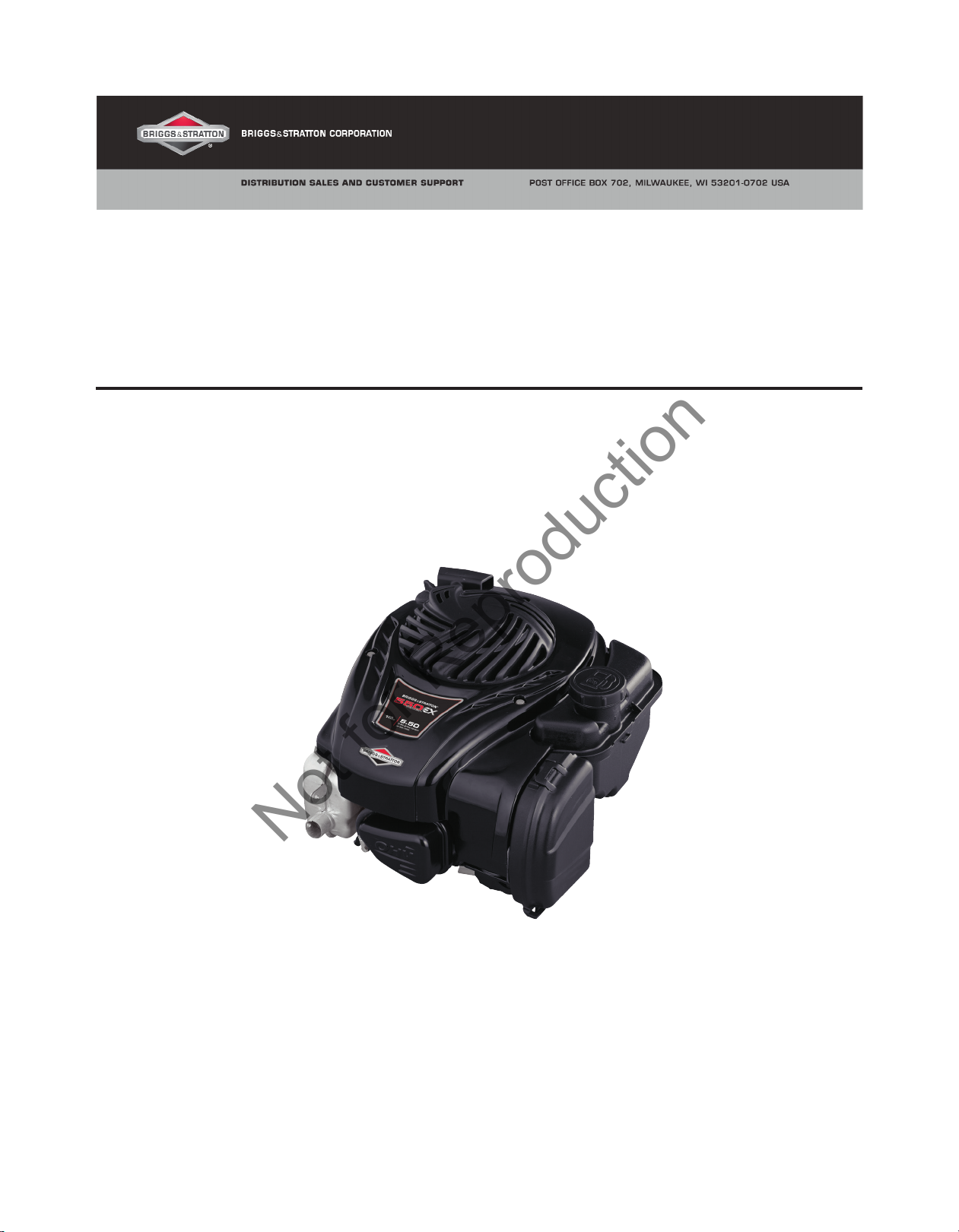
Briggs & Stratton has recently introduced the new E Series™ engine family, which includes the 550e Series™ and
550ex Series™ OHV engines.
This APSI provides basic servicing information in advance of the repair manual currently in development. System
tests and component removal/installation procedures are common with most other Briggs & Stratton engines. See
the Illustrated Parts List for service part numbers. The specifications, part numbers and/or procedures provided
here are PRELIMINARY and subject to change.
85
JULY 2012
INTRODUCTION OF E SERIES™ ENGINES
09P600, 09P700 OHV VERTICAL SHAFT ENGINES
Figure 1
BRIGGS & STRATTON
Distribution Sales & Customer Support
Copyright© 2012 Briggs & Stratton Corporation
All language translations of this document are
derived from the original English source le.
Rev.-
Page 1 of 12
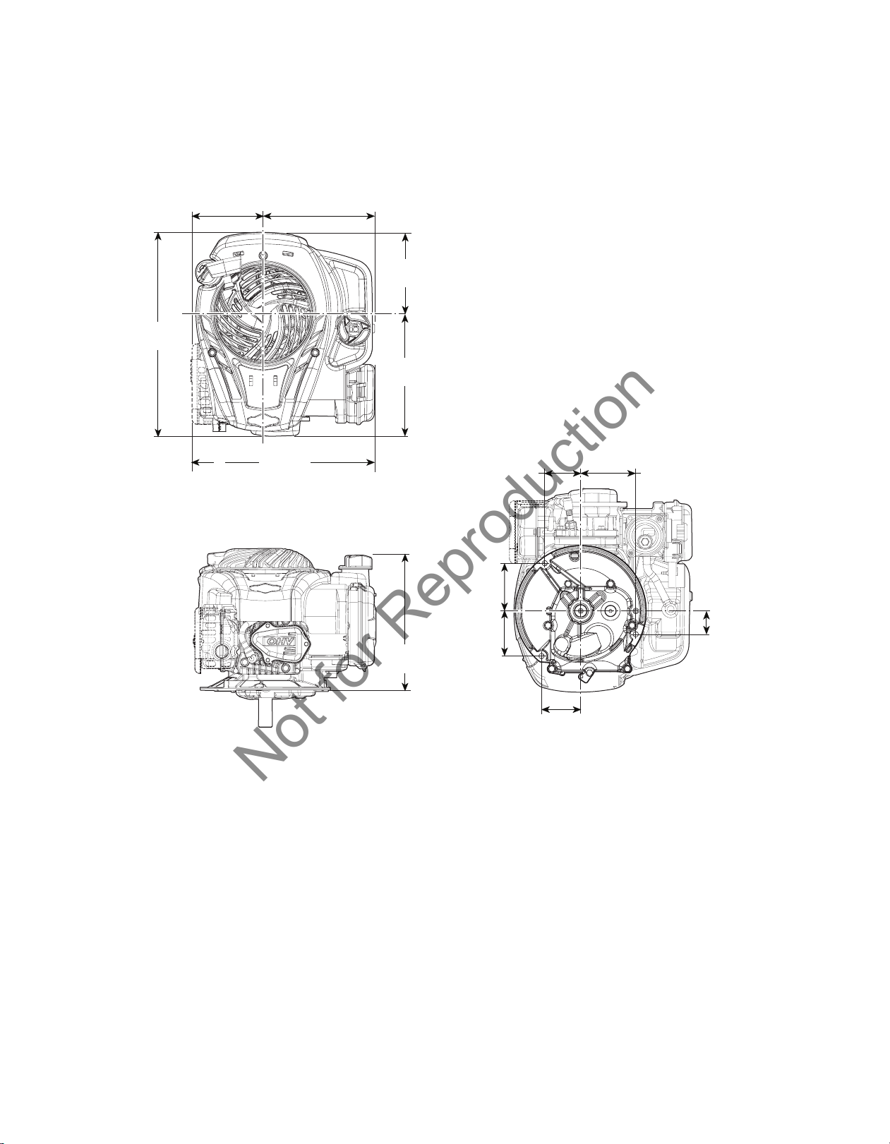
ENGINE DIMENSIONS
4.746
7.442
(345.96)
(39.7)
Not for Reproduction
Dimensions are shown in inches (millimeters).
13.62
(120.54)
(189.04)
7.442
(189.04)
6.21
(157.7)
7.41
(188.3)
9.13
(231.98)
3.19
(81.15)
3.02
(76.68)
2.41
(61.15)
3.68
(93.54)
1.56
Figure 2
Page 2 of 12

SERVICE NOTES
Not for Reproduction
Flywheel
The flywheel overlaps the governor crank at the top of the cylinder. There are two openings in the flywheel casting
to allow access to the governor nut, after the blower housing has been removed.
To remove the flywheel nut, remove the ignition armature and slip a flywheel strap wrench through the armature
opening in the flywheel guard (blower scroll). The flywheel can be removed from the crankshaft using Flywheel
Puller 19069.
Carburetor
For draining the bowl, there is a 1/4-turn hex plug with o-ring installed in the bottom of the float bowl. (CAUTION: Do
not attempt to unscrew the plug, as it is not threaded.)
The float bowl installs in the carburetor in only one direction. There is a cavity molded into the bowl that provides
clearance for the emulsion tube and jet. If the bowl cannot be fully seated into the carburetor by hand, turn it 180
degrees and then reinstall.
Note that the bowl screws are self-tapping. To avoid cross-threading when installing the screws, turn them
counterclockwise until the screw threads drop into place, then tighten clockwise.
The needle valve seat can be removed by threading in a screw, then clamping the screw head in a vise. Carefully
twist and pull on the carburetor body to extract the seat. When installing a replacement seat, make sure the
rounded edge is pressed into the opening in the carburetor body and the flat edge is facing the bowl.
Oil Capacity
This engine requires a reduced oil capacity of just 15 oz (.44 L). A new oil bottle has been designed for service
under part number 100113. The bottle contains the correct amount for this engine in support of our message to
consumers to “pour in the entire bottle”.
Please make sure to remind customers that this engine requires only 15 oz (.44 L) and not the higher capacity of
our other engines.
We anticipate that overfilling could be an issue until customers become accustomed to the difference. Typical
symptoms of overfilling would be white smoke from the exhaust, sparkplug fouling, oil contamination of the air filter
and/or oil leaking from the air filter area.
Blower Housing Barcode Label
In the event that the engine blower housing must be replaced, the barcode label can be transferred to the new
blower housing as follows:
1. After installation, clean the surface of the new blower housing to remove any traces of dust, oil, or grease.
2. Wash hands thoroughly to remove dirt and oils from the skin.
3. Carefully peel off the label from the original blower housing and reposition it in the same location on the new
blower housing.
4. Press firmly to remove any air bubbles and ensure good adhesion.
Page 3 of 12
ASSEMBLY INFORMATION
Not for Reproduction
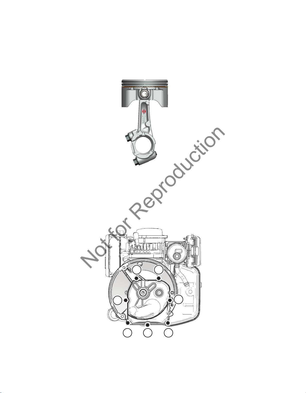
Piston Assembly and Orientation
The notch in the piston, the piston pin clip, and the MAG identification on the connecting rod all face the flywheel
side (mag side) of the engine (Figure 3). When installing replacement piston rings, the paint stripes on the rings
must be to the right side of the ring gaps.
Figure 3
Sump and Seals
Install the sump bolts in positions 1 through 6 (Figure 4). Install the self-tapping sump screw in position 7. Do not
use the self-tapping screw in any other hole location. Using the sequence shown, tighten the bolts to the torque
specification provided in this APSI.
53
6
2
1
7
Figure 4
4
Page 4 of 12

Cylinder Head
Not for Reproduction
Engines built before Date of Manufacture FEB 02 12 (or 120201xx) were equipped with sealant under the rocker
cover. The cover cannot be removed without damaging it. If servicing the cylinder head on these early units, plan
on replacing the rocker cover, and cylinder head plate. Current production engines are equipped with a gasket for
the rocker cover.
The valve guides and the valve seats are not replaceable. If the guides are worn beyond reject size, replace the
head. If the seats are slightly worn, they can be resurfaced to the extent possible with lapping compound; otherwise
replace the cylinder head.
Tighten the four bolts in the sequence shown (Figure 5) to the specification provided in this APSI.
1
3
Figure 5
Apply a bead of sealant to the cylinder head plate before placing it on the head. To set the valve clearance, rotate
the crankshaft PTO counterclockwise four turns to seat the valve train parts, then continue turning until the piston
reaches Top Dead Center (TDC) on the compression stroke. Both valves will be closed. Slowly turn the crankshaft
again until the piston is .250” (6.35 mm) past TDC. Adjust the valve clearance and tighten the rocker ball set screws
to the specification provided in this APSI.
Using a new gasket, install the rocker cover on the cylinder head plate.
Carburetor and Air Cleaner
Make sure the o-ring is installed on the cylinder side of the carburetor spacer, then fit the spacer into the mounting
bracket. Place the bracket and spacer on the cylinder head with the bracket flange to the top (Figure 6). Install and
tighten the two mounting screws to the specification provided in this APSI.
4
2
Page 5 of 12

Figure 6
Not for Reproduction
Both the primer system and the ReadyStart® system have options for a foam element or paper cartridge air
cleaner. The primer systems are shown with foam element version (Figure 7a) and paper cartridge (Figure 7b).
Figure 7a Figure 7b
Install a new gasket in the carburetor flange and a new o-ring and ring retainer into the cylinder side of the venturi.
Assemble the air cleaner base to the carburetor and install two screws and tighten to the specification provided in
this APSI.
Rotate the carburetor to fit the governor link into the throttle lever, then insert the primer hose barb into the slot of
the mounting bracket, and then press the carburetor on the tube of the carburetor spacer. Secure the air cleaner
base to the mounting bracket with two screws and tighten to the specification provided in this APSI. Attach the
primer hose to the primer hose barb (paper cartridge version only).
Page 6 of 12

Control Bracket, Governor Lever, and Governor Spring
Not for Reproduction
Either a fixed speed bracket with a single screw (Figure 8a) or a variable speed bracket with two screws (Figure 8b)
is installed.
Attach the governor spring first to the tab of the fixed or the variable speed bracket, then attach it to the governor
lever from the cylinder side, as shown (Figure 8a or 8b).
Figure 8a Figure 8b
Governor Adjustment Procedure
Static Adjustment
1. Loosen the governor nut.
2. Rotate the throttle linkage from idle to wide open throttle. Note the direction of rotation of the governor lever.
3. Rotate the governor shaft in the direction noted until it stops.
4. While holding the linkage and governor shaft, tighten the governor lever nut to the specification provided in this
APSI.
Dynamic Adjustment
1. Start the engine and allow it to warm up at idle for 3-5 minutes.
2. Move the throttle control (if equipped) to high speed. Using a tang bender, adjust the top no load speed by
bending the tang to obtain the equipment manufacturer’s top no load speed specification.
Spring Color Top No Load Speed
Blue 2600 - 2700
Purple 2800 - 3200
Orange 3200 - 3600
Yellow 3600 - 4000
3. Verify that all speeds meet specifications before returning the engine to service.
Page 7 of 12

Flywheel Brake and Stop Switch Wire
Not for Reproduction
Position the flywheel brake on the cylinder mounting bosses behind the governor crank (Figure 9). Install the long
screw into the hole next to the brake pad. Install the short screw into the hole next to the stop switch. Tighten the
screws to the specification provided in this APSI.
Figure 9
Flywheel Guard (Blower Scroll)
Ensure that the breather tube is fully installed at the back of the air cleaner base and against the cylinder casting
at the breather chamber. Apply a thin bead of sealant (p/n 100106) around the breather (Figure 10). Position the
flywheel guard on the cylinder and install the five screws. Tighten the screws to the specification provided in this
APSI.
Figure 10
Page 8 of 12

Fuel Tank and Fuel Hose
Not for Reproduction
Slide the two mounting tabs of the fuel tank into the slots of the flywheel guard (Figure 11). Press down until the
tank snaps into the metal bosses of the flywheel guard.
Figure 11
Oil Dipstick and Dipstick Tube
The short oil dipstick screws directly into the cylinder. The extended dipstick tube is pressed into the cylinder
and hooks over the edge of the flywheel guard (Figure 12). The tube is held in place when the blower housing is
installed.
Figure 12
Page 9 of 12

Rewind Starter and Blower Housing
Not for Reproduction
The starter rope and the rope handle are the only serviceable parts of the rewind assembly. Place the rewind
assembly inside the blower housing with the handle in the required position (Figure 13a). Align the tabs in the
housing and the rewind and press together until all tabs snap into place. Line up the tabs of the retaining ring
(Figure 13b) with the slots on the rewind and snap it into position.
Figure 13a Figure 13b
ENGINE SPECIFICATIONS
Common Specifications SAE Metric
Armature Air Gap .006 - .014 in .15 - .36 mm
Bore and Stroke 2.49 x 1.75 in 63.4 x 44.5 mm
Crankshaft End Play .002 - .028 in .05 - 1.0 mm
Displacement 8.54 ci 140cc
Exhaust Valve Clearance (Cold) .004 - .008 in .10 - .20 mm
Intake Valve Clearance (Cold) .004 - .008 in .10 - .20 mm
Fuel Tank Capacity .8 qt .8 L
Oil Capacity 15 oz .44 L
Spark Plug Gap .020 in .51 mm
Spark Plug Torque 180 lb-in 20.3 Nm
Page 10 of 12

Common Service Parts Service Number
Not for Reproduction
Air Cleaner Gasket 799580
Air Cleaner Gasket 799581
Air Filter (Foam) 799579
Air Filter (Paper) 798452
Armature 799582
Carburetor (Primer) 799583
Carburetor (Ready Start) 799584
Crankcase Cover Gasket 799587
Cylinder Head Gasket 799586
Fuel Cap, Standard 799684
Fuel Cap, Carbon in Cap 799585
Spark Plug 692051
Starter (Rewind) 799685
Fastener Torque Specication SAE Metric
Air Cleaner Base to Carburetor 25 lb-in 2.8 Nm
Air Cleaner Base to Carburetor Bracket 35 lb-in 4.0 Nm
Armature to Cylinder Block 30 lb-in 3.4 Nm
Blower Housing 35 lb-in 4. 0 Nm
Flywheel Brake 35 lb-in 4.0 Nm
Breather Reed 45 lb-in 5.1 Nm
Carburetor Bracket to Cylinder Head 60 lb-in 6.8 Nm
Casing Clamp 3 lb-in .3 Nm
Connecting Rod 100 lb-in 11.3 Nm
Cylinder Head to Cylinder Block 130 lb-in 14.7 Nm
Sump to Cylinder Block 85 lb-in 9.6 Nm
Control Bracket 65 lb-in 7.3 Nm
Flywheel Guard to Cylinder Block 65 lb-in 7.3 Nm
Flywheel Nut 70 lb-ft 94.9 Nm
Governor Lever Nut 30 lb-in 3.4 Nm
High Oil Dipstick n/a n/a
Low Oil Dipstick 30 lb-in 3.4 nm
Muer 65 lb-in 7.3 Nm
Muer Guard 25 lb-in 2.8 Nm
Rocker Arm Stud 50 lb-in 5.6 Nm
Rocker Arm Setscrew or Nut 25 lb-in 2.8 Nm
Rocker Cover 30 lb-in 3.4 Nm
Sparkplug 180 lb-in 20.3 Nm
Page 11 of 12

Component Standard Dimensions Reject Dimensions
Not for Reproduction
SAE Metric SAE Metric
Cylinder
Mag Bearing .877 in 22.27 .879 in 22.33 mm
Mag Oil Seal Depth Flush Flush N/A N/A
Cam Bearing .501 in 12.73 mm .502 in 12.75 mm
Bore Out-of-Round N/A N/A .0015 in .04 mm
Cylinder Head
Intake
Valve Seat Angle 45° 45° N/A N/A
Valve Stem .156 in 3.96 mm .154 in 3.91 mm
Valve Guide .158 in 4.01 mm .160 in 4.07 mm
Exhaust
Valve Seat Angle 45° 45° N/A N/A
Valve Stem .156 in 3.96 mm .154 in 3.91 mm
Valve Guide .158 in 4.01 mm .160 in 4.07 mm
Crankcase Cover/Sump
PTO Bearing .877 in 22.27 mm .879 in 22.33 mm
PTO Oil Seal Depth Flush Flush N/A N/A
Cam Bearing .501 in 12.73 mm .502 in 12.75 mm
Crankshaft
Crankpin Journal .874 in 22.20 mm .872 in 22.15 mm
Mag Journal .874 in 22.20 mm .872 in 22.15 mm
PTO Journal .874 in 22.20 mm .872 in 22.15 mm
Cam Shaft
Mag-Side Journal .500 in 12.71 mm .499 in 12.67 mm
PTO Side Journal .500 in 12.71 mm .499 in 12.67 mm
Connecting Rod
Crankpin Bearing .875 in 22.24 mm .876 in 22.26 mm
Piston Pin Bore .491 in 12.46 mm .493 in 12.52 mm
Piston and Pin
Pin Diameter .490 in 12.45 mm .489 in 12.42 mm
Piston Pin Bore .491 in 12.46 mm .493 in 12.52 mm
Piston Rings
End Gap-Top .005 in .13 mm .025 in .64 mm
End Gap-Middle .028 in .71 mm .045 in 1.14 mm
End Gap-Oil .030 in .76 mm .045 in 1.14 mm
Ring Land Clearance-Top .002 in .05 mm .003 in .08 mm
Ring Land Clearance-Middle .001 in .03 mm .002 in .03 mm
Ring Land Clearance-Oil .001 in .03 mm .002 in .06 mm
Starter Rope
Rope Diameter .125 in (#4) 3.17 mm (#4) N/A N/A
Rope Length 88.62 in 2.25 m N/A N/A
Page 12 of 12
 Loading...