

Page 1
01894-1
(7000W)
Operator’s Manual
Manuel de l'utilisateur
Manual del Operario
Questions? Help is just a moment away!
Vous avez des questions? Vous n'avez pas besoin d'aller
loin pour trouver de l'aide!
Preguntas? La ayuda es justa un momento lejos!
Call: Generator Helpline
Appelez: Ligne d'assistance de Générateur
Llame: Línea Directa del Generador
1-800-743-4115 M-F 8-5 CT
web: www.briggsandstratton.com
BRIGGS & STRATTON POWER PRODUCTS GROUP, LLC
JEFFERSON,WISCONSIN, U.S.A.
Manual No. 196746GS
Revision B (06/14/2006)
Before using this product, read this
manual and follow all Safety Rules and
Operating Instructions.
WARNING
Antes de utilizar el producto, lea este
manual y siga todas las Reglas de
Seguridad e Instrucciones de Uso.
ADVERTENCIA
Avant d’utiliser ce produit, veuillez lire
le manuel et suivre toutes les directives
relatives à la sécurité et à l’utilisation.
AVERTISSEMENT
Page 2
SAFETY RULES
2
TABLE OF CONTENTS
Safety Rules. . . . . . . . . . . . . . . . . . . . . . . . . . . . . . . . . . . . 2-4
Know Your Generator . . . . . . . . . . . . . . . . . . . . . . . . . . . . . 5
Assembly. . . . . . . . . . . . . . . . . . . . . . . . . . . . . . . . . . . . . . 6-7
Operation . . . . . . . . . . . . . . . . . . . . . . . . . . . . . . . . . . . . 8-14
Maintenance . . . . . . . . . . . . . . . . . . . . . . . . . . . . . . . . . 15-16
Storage . . . . . . . . . . . . . . . . . . . . . . . . . . . . . . . . . . . . . . . . 16
Troubleshooting . . . . . . . . . . . . . . . . . . . . . . . . . . . . . . . . . 17
Notes . . . . . . . . . . . . . . . . . . . . . . . . . . . . . . . . . . . . . . . . . 18
Warranty . . . . . . . . . . . . . . . . . . . . . . . . . . . . . . . . . . . . . . 19
EQUIPMENT
DESCRIPTION
Read this manual carefully and become familiar
with your generator. Know its applications,its
limitations and any hazards involved.
This generator is an engine–driven, revolving field,
alternating current (AC) generator. It was designed to
supply electrical power for operating compatible electrical
lighting, appliances, tools and motor loads.The generator’s
revolving field is driven at about 3,600 rpm by a singlecylinder engine.
CAUTION! DO NOT exceed the generator’s
wattage/amperage capacity. See “Don’t Overload
Generator”.
Every effort has been made to ensure that information in
this manual is accurate and current. However, we reserve
the right to change, alter or otherwise improve the product
and this document at any time without prior notice.
The Emission Control System for this generator is
warranted for standards set by the Environmental
Protection Agency and the California Air Resources Board.
For warranty information refer to the engine operator’s
manual.
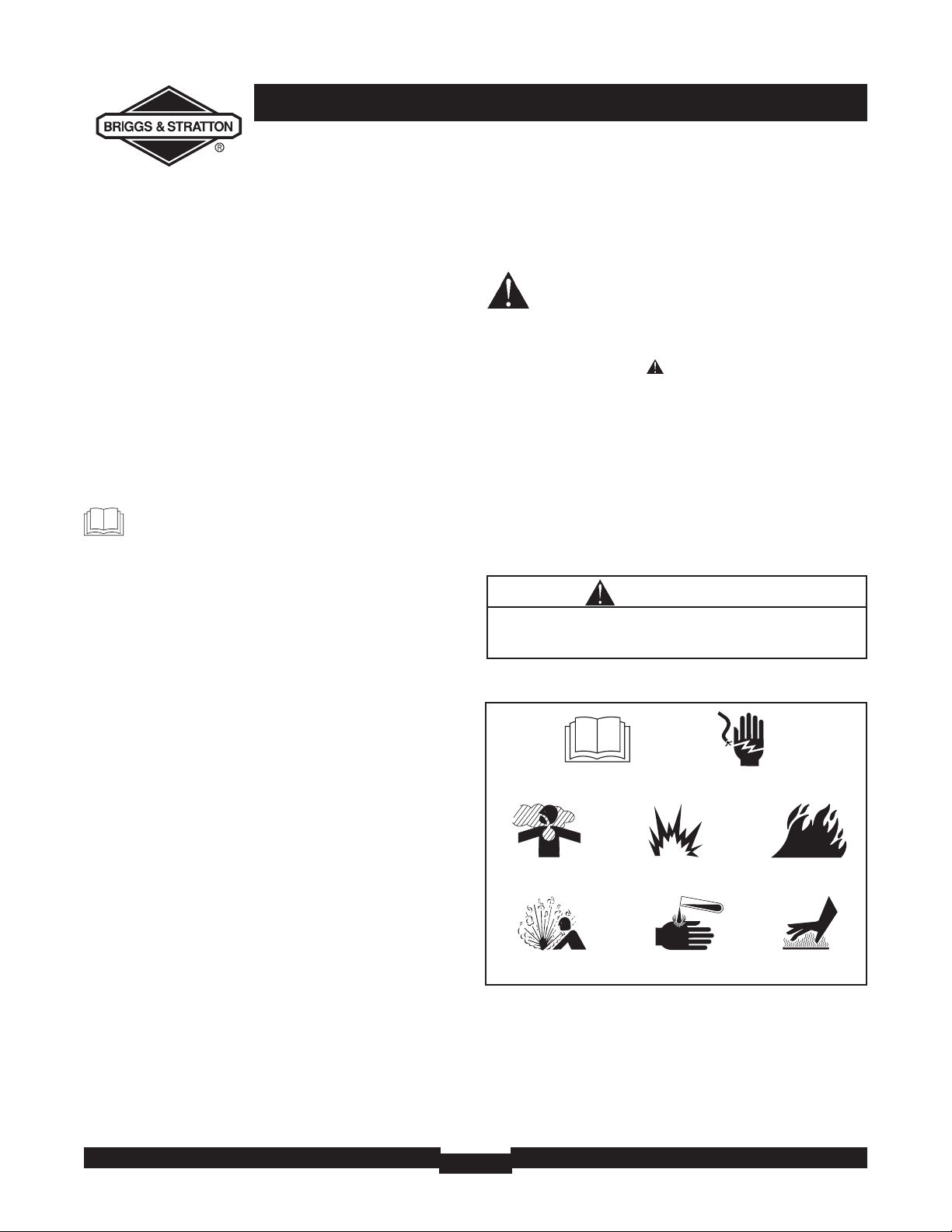
SAFETY RULES
This is the safety alert symbol. It is used to
alert you to potential personal injury hazards.
Obey all safety messages that follow this
symbol to avoid possible injury or death.
The safety alert symbol ( ) is used with a signal word
(DANGER, CAUTION,WARNING), a pictorial and/or a
safety message to alert you to hazards. DANGER indicates
a hazard which, if not avoided, will result in death or
serious injury. WARNING indicates a hazard which, if not
avoided, could result in death or serious injury.
CAUTION indicates a hazard which, if not avoided,might
result in minor or moderate injury. CAUTION, when used
without the alert symbol, indicates a situation that could
result in equipment damage. Follow safety messages to
avoid or reduce the risk of injury or death.
Hazard Symbols and Meanings
The engine exhaust from this product contains
chemicals known to the State of California to cause
cancer, birth defects, or other reproductive harm.
WARNING
Fire
Explosion
Toxic Fumes
Hot Surface
Operator’s Manual
Electrical Shock
Explosive Pressure
Chemical Burn
SAVE THESE INSTRUCTIONS
Copyright © 2006 Briggs & Stratton Power Products
Group, LLC. All rights reserved. No part of this material
may be reproduced or transmitted in any form by any
means without the express written permission of Briggs &
Stratton Power Products Group, LLC.
Page 3
3
SAFETY RULES
• This generator does not meet U. S. Coast Guard Regulation
33CFR-183 and should not be used on marine applications.
• Failure to use the appropriate U. S. Coast Guard approved
generator could result in bodily injury and/or property
damage.
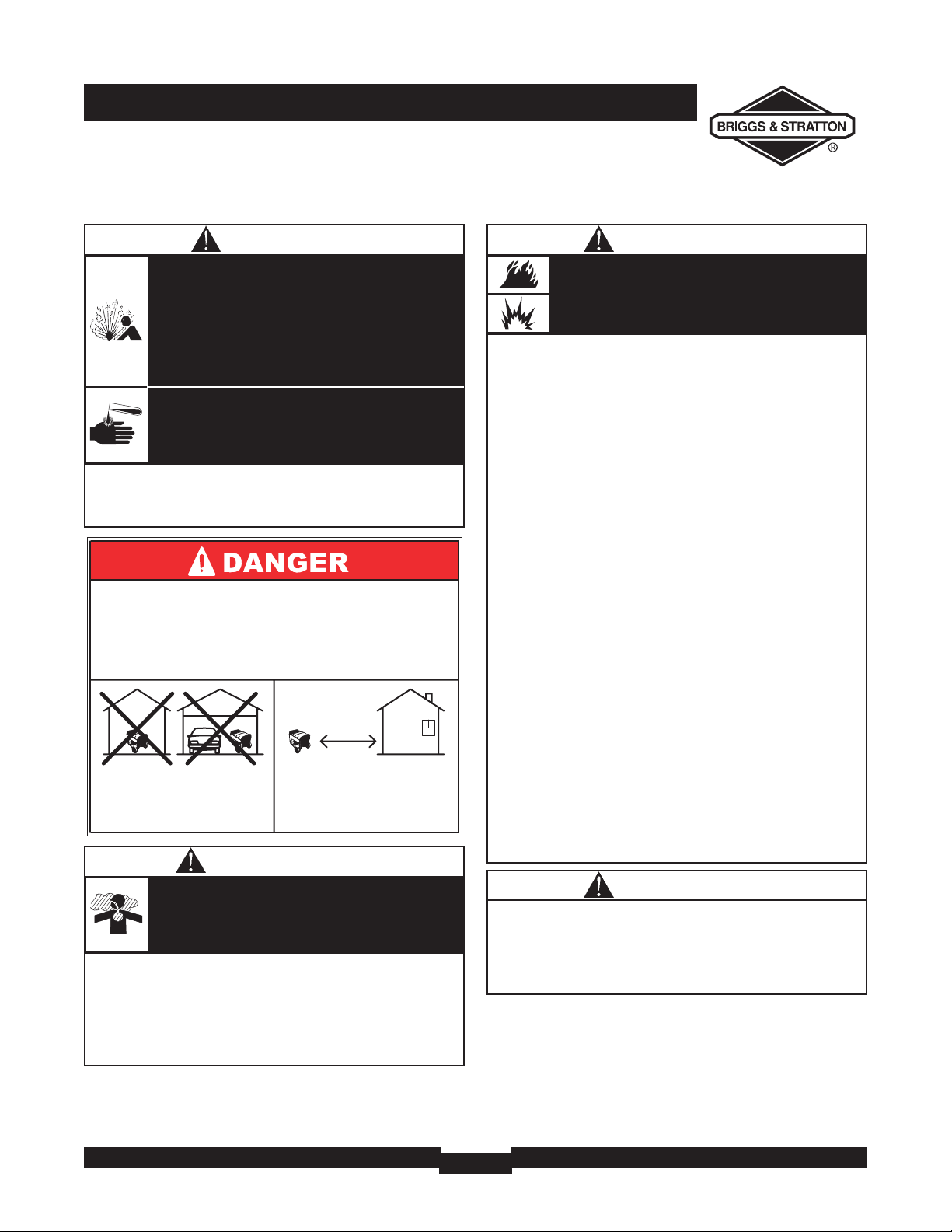
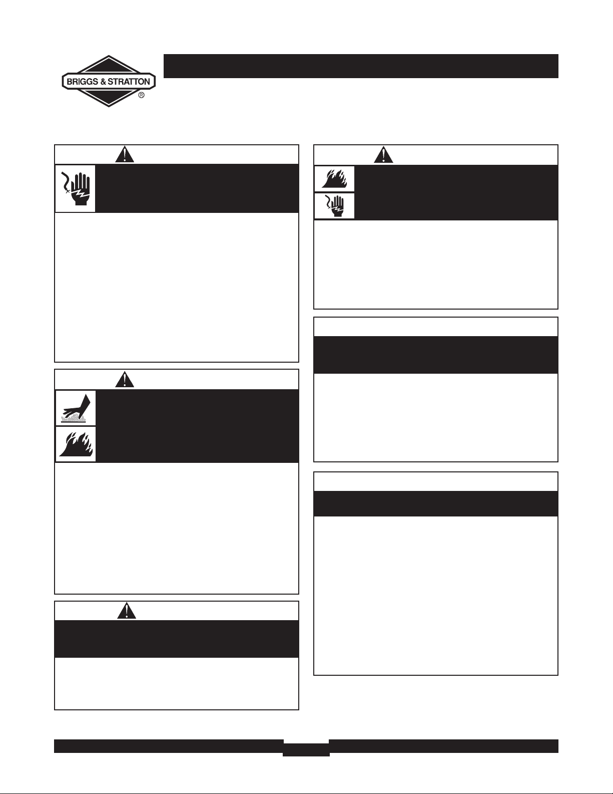
WARNING
• DO NOT allow any open flame, spark, heat, or lit cigarette
during and for several minutes after charging a battery.
• Wear protective goggles, rubber apron,and rubber gloves.
Storage batteries give off explosive hydrogen gas
during recharging.
Hydrogen gas stays near battery for a long time
after battery has been charged.
Slightest spark will ignite hydrogen and cause
explosion.
You can be blinded or severely injured.
Battery electrolyte fluid contains acid and is
extremely caustic.
Contact with battery fluid will cause severe
chemical burns.
DANGER
WHEN ADDING OR DRAINING FUEL
• Turn generator OFF and let it cool at least 2 minutes before
removing fuel cap.Loosen cap slowly to relieve pressure in
tank.
• Fill or drain fuel tank outdoors.
• DO NOT overfill tank.Allow space for fuel expansion.
• If fuel spills, wait until it evaporates before starting engine.
• Keep fuel away from sparks, open flames, pilot lights, heat, and
other ignition sources.
• DO NOT light a cigarette or smoke.
WHEN STARTING EQUIPMENT
• Ensure spark plug, muffler, fuel cap and air cleaner are in place.
• DO NOT crank engine with spark plug removed.
WHEN OPERATING EQUIPMENT
• Do not tip engine or equipment at angle which causes fuel to
spill.
• This generator is not for use in mobile equipment or marine
applications.
WHEN TRANSPORTING OR REPAIRING
EQUIPMENT
• Transport/repair with fuel tank EMPTY or with fuel shutoff
valve OFF.
• Disconnect spark plug wire.
WHEN STORING FUEL OR EQUIPMENT WITH FUEL
IN TANK
• Store away from furnaces,stoves, water heaters, clothes
dryers or other appliances that have pilot light or other
ignition source because they can ignite fuel vapors.
Fuel and its vapors are extremely flammable and
explosive.
Fire or explosion can cause severe burns or
death.
WARNING
• Operate generator ONLY outdoors.
• Keep exhaust gas from entering a confined area through
windows, doors, ventilation intakes or other openings.
• DO NOT operate generator inside any building or enclosure
(even if doors or windows are open),including the generator
compartment of a recreational vehicle (RV).
Running generator gives off carbon monoxide,
an odorless, colorless, poison gas.
Breathing carbon monoxide can cause nausea,
fainting or death.
WARNING
Using a generator indoors WILL KILL YOU
IN MINUTES.
Exhaust contains carbon monoxide, a
poison gas you cannot see or smell.
NEVER use in the home
or in partly enclosed
areas such as garages.
ONLY use outdoors and
far from open windows,
doors, and vents.
Page 4
SAFETY RULES
4
• DO NOT tamper with governed speed. Generator supplies
correct rated frequency and voltage when running at governed
speed.
• DO NOT modify generator in any way.
Excessively high operating speeds increase risk of injury
and damage to generator.
Excessively low speeds impose a heavy load.
CAUTION
• See “Don’t Overload Generator”.
• Start generator and let engine stabilize before connecting
electrical loads.
• Connect electrical loads in OFF position, then turn ON for
operation.
• Turn electrical loads OFF and disconnect from generator
before stopping generator.
Exceeding generators wattage/amperage capacity can
damage generator and/or electrical devices connected
to it.
CAUTION
• Use generator only for intended uses.
• If you have questions about intended use, ask dealer or call
1-800-743-4115.
• Operate generator only on level surfaces.
• DO NOT expose generator to excessive moisture, dust, dirt,
or corrosive vapors.
• DO NOT insert any objects through cooling slots.
• If connected devices overheat, turn them off and disconnect
them from generator.
• Shut off generator if:
-electrical output is lost;
-equipment sparks, smokes, or emits flames;
-unit vibrates excessively.
Improper treatment of generator can damage it and
shorten its life.
CAUTION
WHEN ADJUSTING OR MAKING REPAIRS TO YOUR
GENERATOR
• Disconnect the spark plug wire from the spark plug and place
the wire where it cannot contact spark plug.
WHEN TESTING FOR ENGINE SPARK
• Use approved spark plug tester.
• DO NOT check for spark with spark plug removed.
Unintentional sparking can result in fire or
electric shock.
WARNING
• DO NOT touch hot surfaces and avoid hot exhaust gases.
• Allow equipment to cool before touching.
• Keep at least 5 ft. (152 cm) clearance on all sides of generator
including overhead.
• Code of Federal Regulation (CFR) Title 36 Parks, Forests,and
Public Property require equipment powered by an internal
combustion engine to have a spark arrester, maintained in
effective working order, complying to USDA Forest service
standard 5100-1C or later revision. In the State of California a
spark arrester is required under section 4442 of the California
Public resources code. Other states may have similar laws.
Running engines produce heat.Temperature of
muffler and nearby areas can reach or exceed
150°F (65°C).
Severe burns can occur on contact.
Exhaust heat/gases can ignite combustibles,
structures or damage fuel tank causing a fire.
WARNING
• When using generator for backup power, notify utility
company. Use approved transfer equipment to isolate
generator from electric utility.
• Use a ground fault circuit interrupter (GFCI) in any damp or
highly conductive area, such as metal decking or steel work.
• DO NOT touch bare wires or receptacles.
• DO NOT use generator with electrical cords which are worn,
frayed, bare or otherwise damaged.
• DO NOT operate generator in the rain or wet weather.
• DO NOT handle generator or electrical cords while standing
in water, while barefoot,or while hands or feet are wet.
• DO NOT allow unqualified persons or children to operate or
service generator.
Generator produces powerful voltage.
Failure to isolate generator from power utility
can result in death or injury to electric utility
workers due to backfeed of electrical energy.
WARNING
Page 5
5
KNOW YOUR GENERATOR
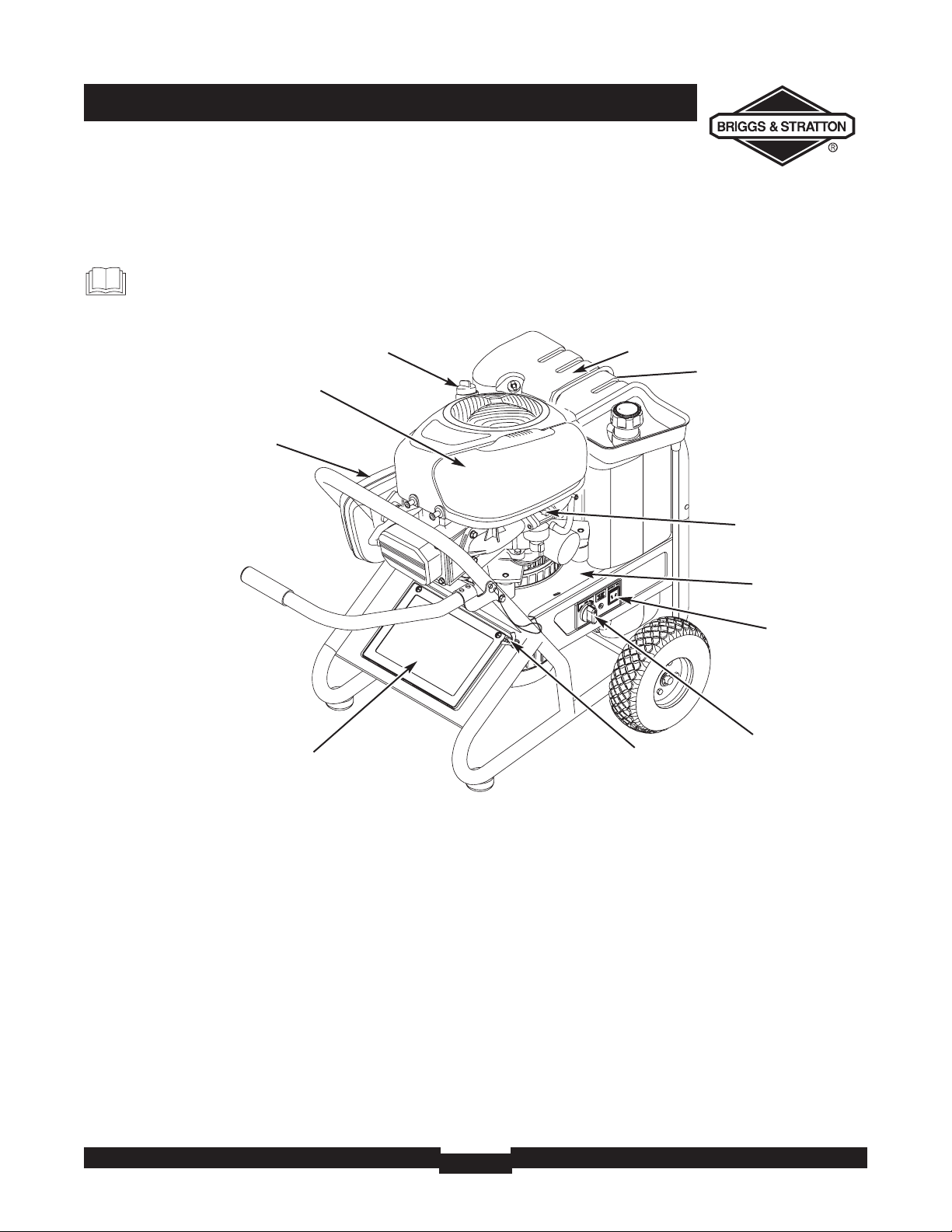
KNOW YOUR GENERATOR
Read this Operator’s Manual and safety rules before operating your generator.
Compare the illustrations with your generator, to familiarize yourself with the locations of various controls and
adjustments. Save this manual for future reference.
12 Volt DC Receptacle — Use this receptacle with
battery charge cables to charge a 12 Volt battery.
120 Volt AC, 20 Amp Duplex Receptacles — May be
used to supply electrical power for the operation of 120Volt
AC, 20 Amp, single phase, 60 Hz electrical lighting, appliance,
tool and motor loads.
120/240 Volt AC, 30 Amp Locking Receptacle — May
be used to supply electrical power for the operation of
120 and/or 240 Volt AC, 30 Amp, single phase, 60 Hz
electrical lighting, appliance, tool and motor loads.
Air Cleaner —
Protects engine by filtering dust and debris
out of intake air.
Battery — Located behind plastic cover. 12 Volt DC sealed
battery provides power to start the engine.
Choke Lever — Used when starting a cold engine.
Circuit Breakers (AC) — The 120 Volt AC, 20A duplex
receptacles are provided with "push to reset" circuit
breakers to protect the generator against electrical overload.
Data Tag – Provides model, revision and serial number of
generator. Please have these readily available if calling for
assistance.
Fuel Tank — Capacity of seven (7) U.S. gallons.
Start Switch — Turn to start the engine.
Grounding Fastener — If required, please consult a
qualified electrician, electrical inspector, or local agency
having jurisdiction.
Oil Fill Cap — Add oil to engine here.
Spark Arrester Muffler — Exhaust muffler lowers engine
noise and is equipped with a spark arrester screen.
Rocker Switch Circuit Breaker — The 120/240 Volt AC,
30A locking receptacle is provided with a rocker switch circuit
breaker to protect the generator against electrical overload.
This switch also controls all receptacles.
Choke Lever
Rocker Switch Circuit
Breaker
Circuit Breakers (AC)
120 Volt AC, 20 Amp
Duplex Receptacles
120/240 Volt AC, 30 Amp
Locking Receptacle
12 Volt DC
Receptacle
Spark Arrester Muffler
Start Switch
Grounding
Fastener
Air Cleaner
Fuel Tank
Oil Fill Cap
Data Tag
Battery
Page 6
ASSEMBLY
6
ASSEMBLY
Your generator requires some assembly and is ready for
use after it has been properly serviced with the
recommended oil and fuel.
If you have any problems with the assembly of your
generator, please call the generator helpline at
1-800-743-4115. If calling for assistance, please have the
model, revision,and serial number from the data tag available.
See “Know Your Generator” for data tag location.
Unpacking the Generator
1. Set the carton on a rigid flat surface.
2. Open carton completely by cutting each corner from
top to bottom.
3. Remove all packing material, carton fillers, etc.
4. Remove generator from shipping carton.
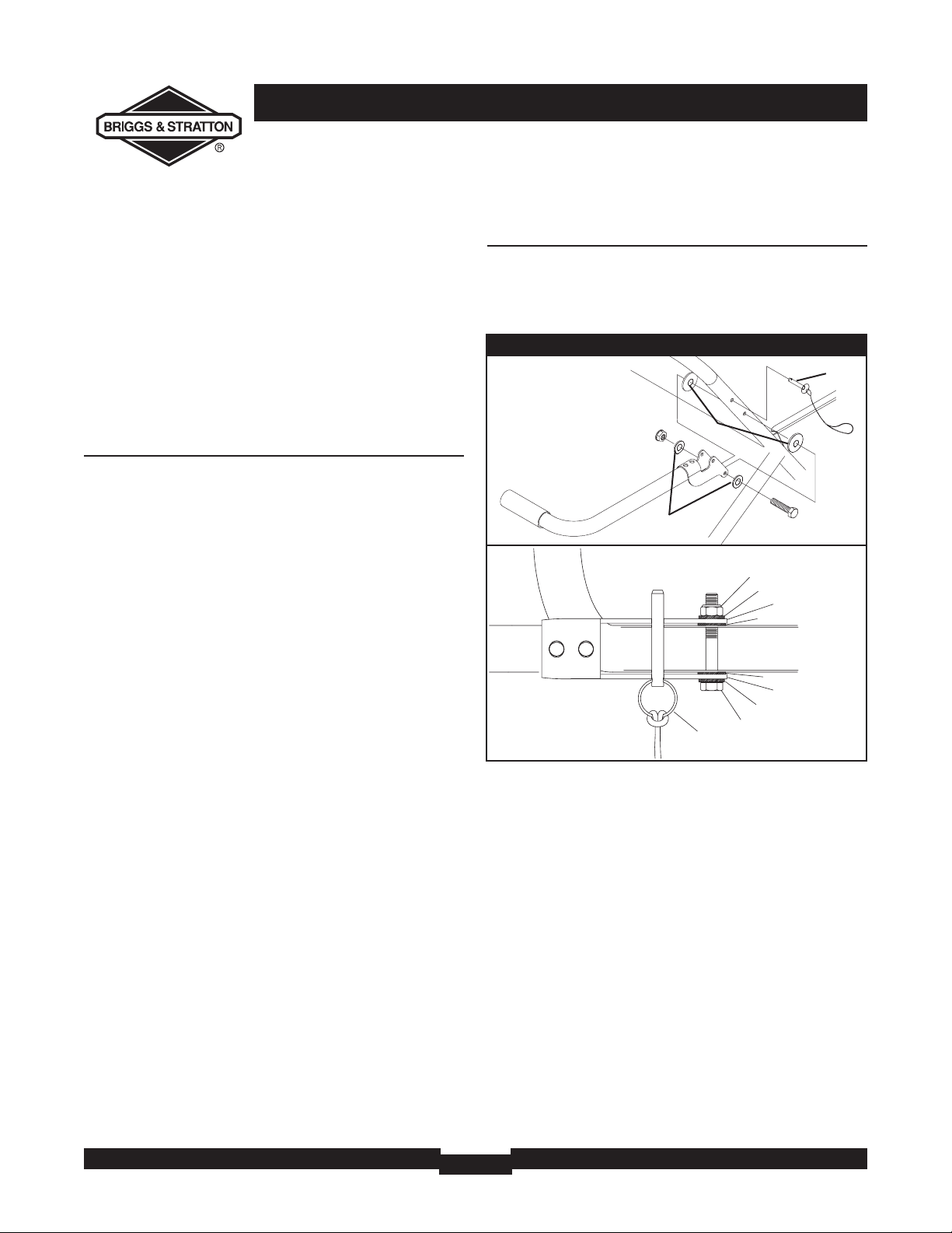
Attach Handle
You will need two 1/2” or 13mm wrenches to attach handle.
1. Attach handle to right side of generator frame (viewing
unit from front), as shown in Figure 1, with a 60 mm
capscrew, flat washers, nylon washers, and lock nut.
NOTE: DO NOT overtighten. Handle must be able to
move up and down freely.
2. Raise handle and insert handle pin to move generator.
60mm Capscrew
Nylon Washers
Flat Washers
Lock Nut
Handle Pin
Figure 1 — Attach Handle
Nut
Washer
Nylon Washer
Handle Bracket
Nylon Washer
Handle Bracket
Washer
60mm Capscrew
Handle Pin
Page 7
7
ASSEMBLY
BEFORE STARTING THE
ENGINE
Add Engine Oil
• Place generator on a level surface.
• Refer to engine operator’s manual and follow oil
recommendations and instructions.
NOTE: Check oil often during engine break–in. Refer to
engine operator’s manual for recommendations.
NOTE:The generator assembly rotates on a prelubricated
and sealed ball bearing that requires no additional
lubrication for the life of the bearing.
Add Fuel
NOTE:This gasoline engine is certified to operate on
gasoline. Exhaust Emission Control System: EM (Engine
Modifications).
1. Use clean, fresh, regular UNLEADED gasoline with a
minimum of 87 octane. DO NOT use fuel which
contains Methanol. DO NOT mix oil with fuel.
2. Clean area around fuel fill cap, remove cap.
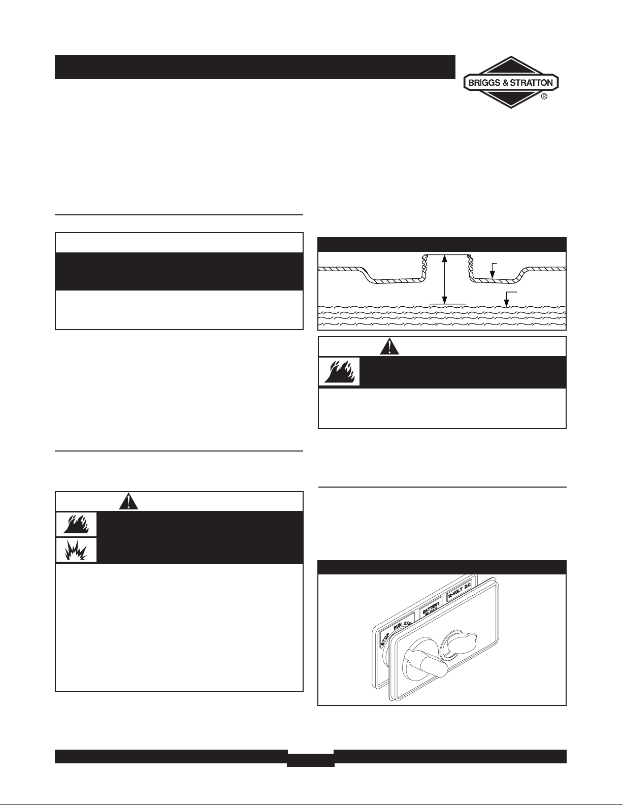
3. Slowly add regular unleaded fuel to fuel tank. Be careful
not to overfill.Allow at least 2.25" of tank space for
fuel expansion (Figure 2).
4. Install fuel cap and let any spilled fuel evaporate before
starting engine.
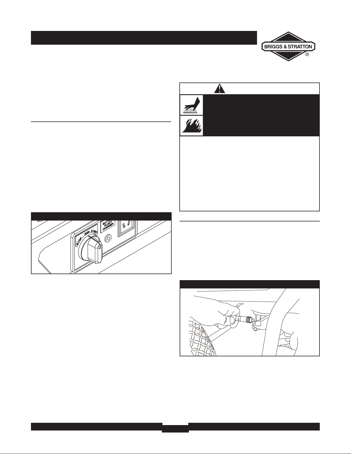
Remove Cover on Start Switch
A protective plastic cover is placed over the start switch to
prevent the generator from being started.
• Open cap on battery float charger.
• Remove and discard plastic cover over the start switch
(Figure 3).
• Replace cap on battery float charger.
CAUTION
• Refer to engine operator’s manual for oil fill information.
• Damage to equipment resulting from failure to follow this
instruction will void warranty.
Any attempt to crank or start the engine before it has
been properly filled with the recommended oil will result
in equipment failure.
WHEN ADDING FUEL
• Turn generator OFF and let it cool at least 2 minutes before
removing fuel cap.Loosen cap slowly to relieve pressure in
tank.
• Fill fuel tank outdoors.
• DO NOT overfill tank.Allow space for fuel expansion.
• Wait for spilled fuel to evaporate before starting engine.
• Keep fuel away from sparks, open flames, pilot lights, heat, and
other ignition sources.
• DO NOT light a cigarette or smoke.
Fuel and its vapors are extremely flammable and
explosive.
Fire or explosion can cause severe burns or
death.
WARNING
Fuel
Tank
2.25” Air Space
Figure 2 - Fuel Expansion
Figure 3 — Remove Cover on Start Switch
• Replace “1.5” with “2.25” fuel fill level given in engine manual.
• Failure to follow this instruction may cause fuel to overexpand
and spill from tank.
Fill tank to approximately 2.25” below top of
neck to allow for fuel expansion.
WARNING
Page 8
OPERATION
8
USING THE GENERATOR
System Ground
The generator has a system ground that connects the
generator frame components to the ground terminals on
the AC output receptacles.The system ground is connected
to the AC neutral wire (the neutral is bonded to the
generator frame).
Special Requirements
There may be Federal or State Occupational Safety and
Health Administration (OSHA) regulations, local codes, or
ordinances that apply to the intended use of the generator.
Please consult a qualified electrician, electrical inspector, or
the local agency having jurisdiction.
• In some areas, generators are required to be registered
with local utility companies.
• If the generator is used at a construction site, there may
be additional regulations which must be observed.
Connecting to a Building’s Electrical
System
Connections for standby power to a building’s electrical
system must be made by a qualified electrician.The
connection must isolate the generator power from utility
power, and must comply with all applicable laws and
electrical codes.
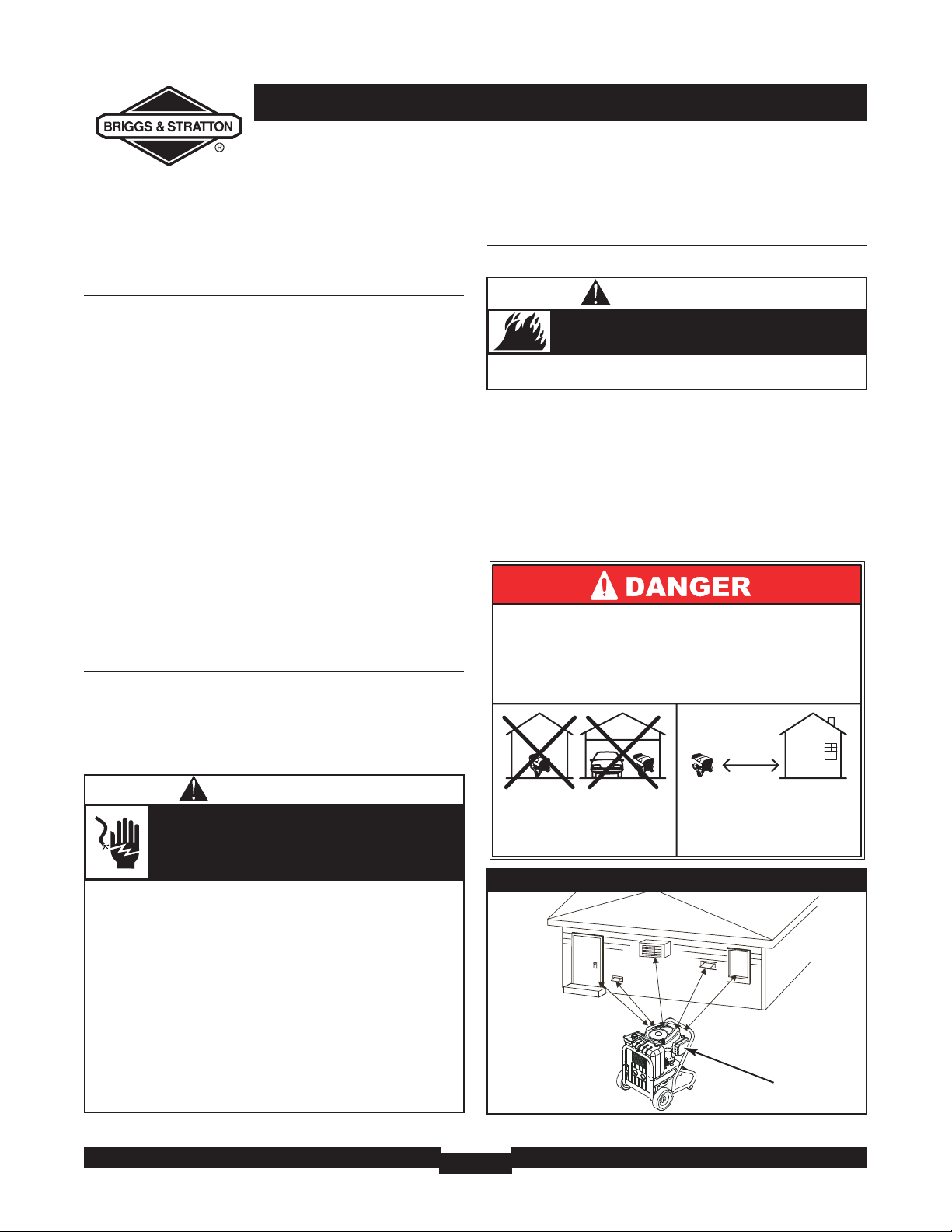
Generator Location
Generator Clearance
Place generator in a well ventilated area, which will allow
for removal of deadly exhaust gas. DO NOT place
generator where exhaust gas could accumulate and enter
inside or be drawn into a potentially occupied building.
Ensure exhaust gas is kept away from any windows, doors,
ventilation intakes or other openings that can allow exhaust
gas to collect in a confined area (Figure 4). Prevailing winds
and air currents should be taken into consideration when
positioning generator.
Figure 4 — Generator Clearance
Exhaust Port
• When using generator for backup power, notify utility
company. Use approved transfer equipment to isolate
generator from electric utility.
• Use a ground fault circuit interrupter (GFCI) in any damp or
highly conductive area, such as metal decking or steel work.
• DO NOT touch bare wires or receptacles.
• DO NOT use generator with electrical cords which are worn,
frayed, bare or otherwise damaged.
• DO NOT operate generator in the rain or wet weather.
• DO NOT handle generator or electrical cords while standing
in water, while barefoot,or while hands or feet are wet.
• DO NOT allow unqualified persons or children to operate or
service generator.
Generator produces powerful voltage.
Failure to isolate generator from power utility
can result in death or injury to electric utility
workers due to backfeed of electrical energy.
WARNING
• Keep at least 5 ft. (152 cm) clearance on all sides of generator
including overhead.
Exhaust heat/gases can ignite combustibles,
structures or damage fuel tank causing a fire.
WARNING
Using a generator indoors WILL KILL YOU
IN MINUTES.
Exhaust contains carbon monoxide, a
poison gas you cannot see or smell.
NEVER use in the home
or in partly enclosed
areas such as garages.
ONLY use outdoors and
far from open windows,
doors, and vents.
Page 9
9
OPERATION
OPERATING THE
GENERATOR
Starting the Engine
IMPORTANT:Always unplug the battery float charger
before starting the generator.
Disconnect all electrical loads from the generator. Follow
start instruction steps in numerical order:
1. Make sure unit is on a level surface.
IMPORTANT: Failure to start and operate unit on a level
surface will cause the unit not to start or shut down during
operation.
2. Follow start instructions given in engine operator’s
manual and turn start switch on generator to “Start”
position (Figure 5).
To prolong the life of starter components, DO NOT
hold starter switch in “Start” position for more than
15 seconds, and pause for 1 minute.
NOTE: If engine starts but fails to run, or if unit shuts down
during operation, make sure unit is on a level surface and
check for proper oil level in crankcase.This unit may be
equipped with a low oil protection device. See engine
operator’s manual.
Jump Start Procedure
If the generator’s starting battery fails, use the following
instructions to jump start your generator.You can jump
start the generator using any 12 Volt automotive or utility
style storage battery.
1. Unscrew the fuse holder and remove the generator’s
10 Amp in-line fuse (Figure 6).Verify the fuse is good
or replace with a known good fuse. Reinstall fuse in
the fuse holder.
2. Slide the red rubber boot off the generator’s battery
terminal and push it onto the red wire, thus
uncovering the POSITIVE battery terminal.
Figure 6 — In-Line Fuse
Figure 5 — Starter Switch
• DO NOT touch hot surfaces and avoid hot exhaust gases.
• Allow equipment to cool before touching.
• Keep at least 5 ft. (152 cm) clearance on all sides of generator
including overhead.
• Code of Federal Regulation (CFR) Title 36 Parks, Forests,and
Public Property require equipment powered by an internal
combustion engine to have a spark arrester, maintained in
effective working order, complying to USDA Forest service
standard 5100-1C or later revision. In the State of California a
spark arrester is required under section 4442 of the California
Public resources code. Other states may have similar laws.
Running engines produce heat.Temperature of
muffler and nearby areas can reach or exceed
150°F (65°C).
Severe burns can occur on contact.
Exhaust heat/gases can ignite combustibles,
structures or damage fuel tank causing a fire.
WARNING
Page 10
OPERATION
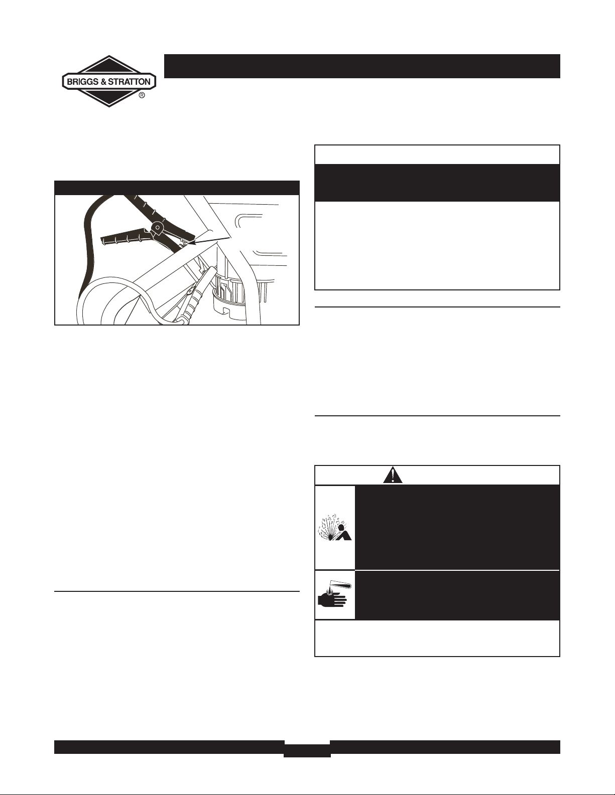
10
3. Using standard automotive jumper cables, connect the
RED jumper cable clamp to the generator’s POSITIVE
battery terminal (Figure 7).
4. Connect the other RED jumper cable clamp to the
starting battery’s POSITIVE battery terminal.
5. Connect the BLACK jumper cable clamp to the
starting battery’s NEGATIVE battery terminal.
6. Connect the other BLACK jumper cable clamp to the
GROUNDING FASTENER on the generator, as shown
in Figure 7.
7. Start the generator as described in “Starting the
Engine” and remove jumper cables in reverse order of
connections.
8. Slide the red rubber boot back onto the generator’s
POSITIVE battery terminal.
If you have any questions, please call the Generator
Helpline at 1-800-743-4115, M-F 8-5 CT.
IMPORTANT:When jump starting, always wear proper eye
protection and never lean over battery.Inspect both
batteries before connecting booster cables. DO NOT jump
start a damaged battery. Be sure vent caps are tight and level.
Connecting Electrical Loads
• Let engine stabilize and warm up for a few minutes after
starting.
• Plug in and turn on the desired 120 and/or 240 Volt AC,
single phase, 60 Hz electrical loads.
• DO NOT connect 240 Volt loads to the 120 Volt
receptacles.
• DO NOT connect 3–phase loads to the generator.
• DO NOT connect 50 Hz loads to the generator.
• DO NOT OVERLOAD GENERATOR. See “Don’t
Overload Generator”.
Stopping the Engine
1. Unplug all electrical loads from generator panel
receptacles. NEVER start or stop engine with electrical
devices plugged in and turned on.
2. Let engine run at no–load for 30 seconds to stabilize
the internal temperatures of engine and generator.
3. Turn start switch to “Stop” position.
Charging a Battery
Your generator has the capability of recharging a discharged
12 Volt automotive or utility style storage battery. DO
NOT use the unit to charge any 6 Volt batteries. DO NOT
use the unit to crank an engine having a discharged battery.
To recharge 12 Volt batteries, proceed as follows:
1. Check fluid level in all battery cells. If necessary, add
ONLY distilled water to cover separators in battery
cells. DO NOT use tap water.
• DO NOT allow any open flame, spark, heat, or lit cigarette
during and for several minutes after charging a battery.
• Wear protective goggles, rubber apron,and rubber gloves.
Storage batteries give off explosive hydrogen gas
during recharging.
Hydrogen gas stays near battery for a long time
after battery has been charged.
Slightest spark will ignite hydrogen and cause
explosion.
You can be blinded or severely injured.
Battery electrolyte fluid contains acid and is
extremely caustic.
Contact with battery fluid will cause severe
chemical burns.
DANGER
Figure 7 — Jumper Cable Connections
Grounding
Fastener
• See “Don’t Overload Generator”.
• Start generator and let engine stabilize before connecting
electrical loads.
• Connect electrical loads in OFF position, then turn ON for
operation.
• Turn electrical loads OFF and disconnect from generator
before stopping generator.
Exceeding generators wattage/amperage capacity can
damage generator and/or electrical devices connected
to it.
CAUTION
Page 11
11
OPERATION
2. If battery is equipped with vent caps, make sure they
are installed and are tight.
3. If necessary, clean battery terminals.
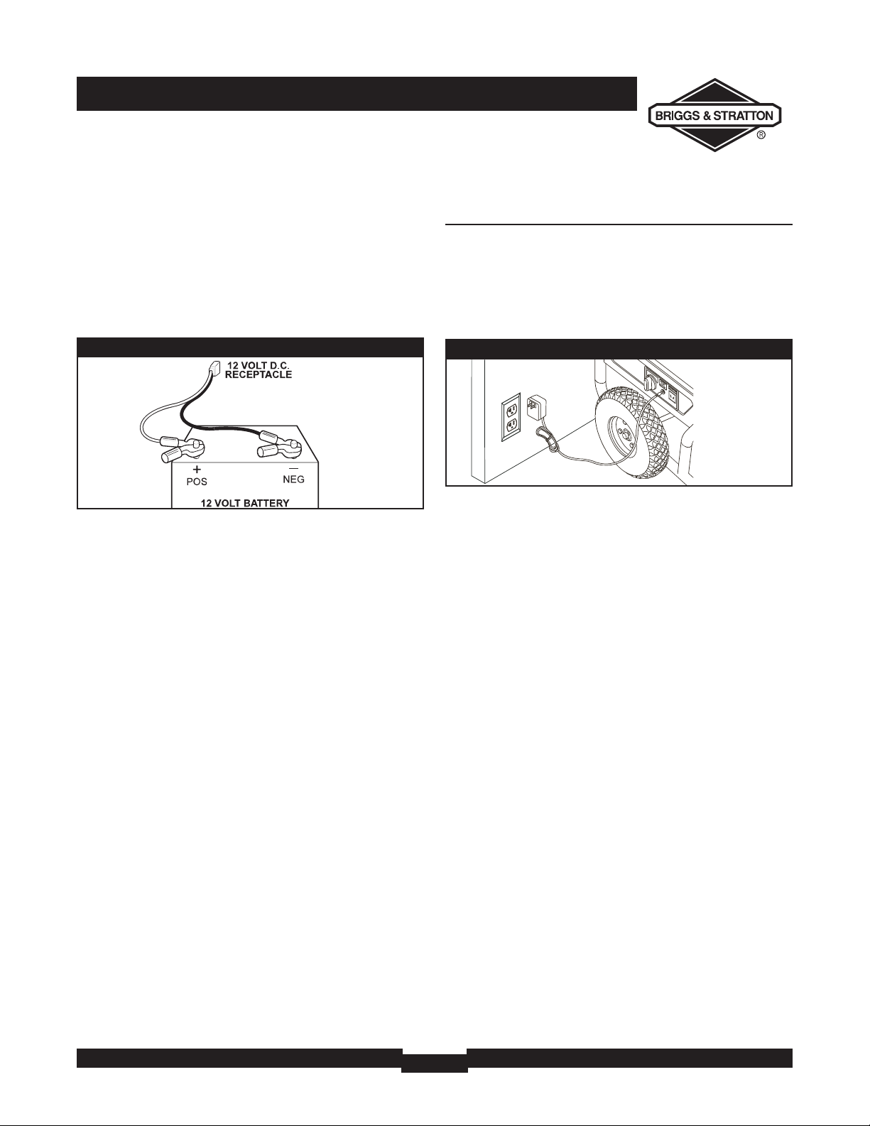
4. Connect battery charge cable connector plug to panel
receptacle identified by the words “12-VOLTS D.C.”
5. Connect battery charge cable clamp with red handle
to positive (+) battery terminal (Figure 8).
6. Connect battery charge cable clamp with black handle
to negative (–) battery terminal (Figure 8).
7. Start engine. Let engine run while battery recharges.
8. When battery has charged, shut down engine
NOTE:Use an automotive hydrometer to test battery
state of charge and condition. Follow the hydrometer
manufacturer’s instructions carefully. Generally, a battery is
considered to be at 100% state of charge when specific
gravity of its fluid (as measured by hydrometer) is 1.260 or
higher.
How to Use the Battery Charger
Use battery float charger jack to keep the starting battery
charged and ready for use. Battery charging should be done
in a dry location, such as inside a garage.
1. Plug charger into unit’s “Battery Float Charger” jack,
which is located on starter switch panel (Figure 9). Plug
battery charger into a 120 Volt AC wall receptacle.
2. Unplug charger from unit and wall outlet when
generator is being started and while in operation.
3. Keep charger plugged in when generator is not in use
to prolong battery life.The charger has a built in float
equalizer and will not overcharge battery, even when
plugged in for an extended period of time.
IMPORTANT: See “Battery Maintenance” on page 16 for
additional information.
COLD WEATHER
OPERATION
Under certain weather conditions (temperatures below
40°F [4°C] combined with high humidity), your generator
may experience icing of the carburetor and/or the
crankcase breather system.To reduce this problem, you
need to perform the following:
1. Make sure generator has clean, fresh fuel.
2. Open fuel valve (turn valve to open position).
3. Use SAE 5W-30 oil (synthetic preferred, see engine
operator’s manual).
4. Check oil level daily or after every eight (8) hours of
operation.
5. Maintain generator following “Maintenance Schedule”
in engine operator’s manual.
6. Shelter unit from elements.
Figure 8 — Battery Connections
Figure 9 — Battery Charger Jack
Page 12
OPERATION
12
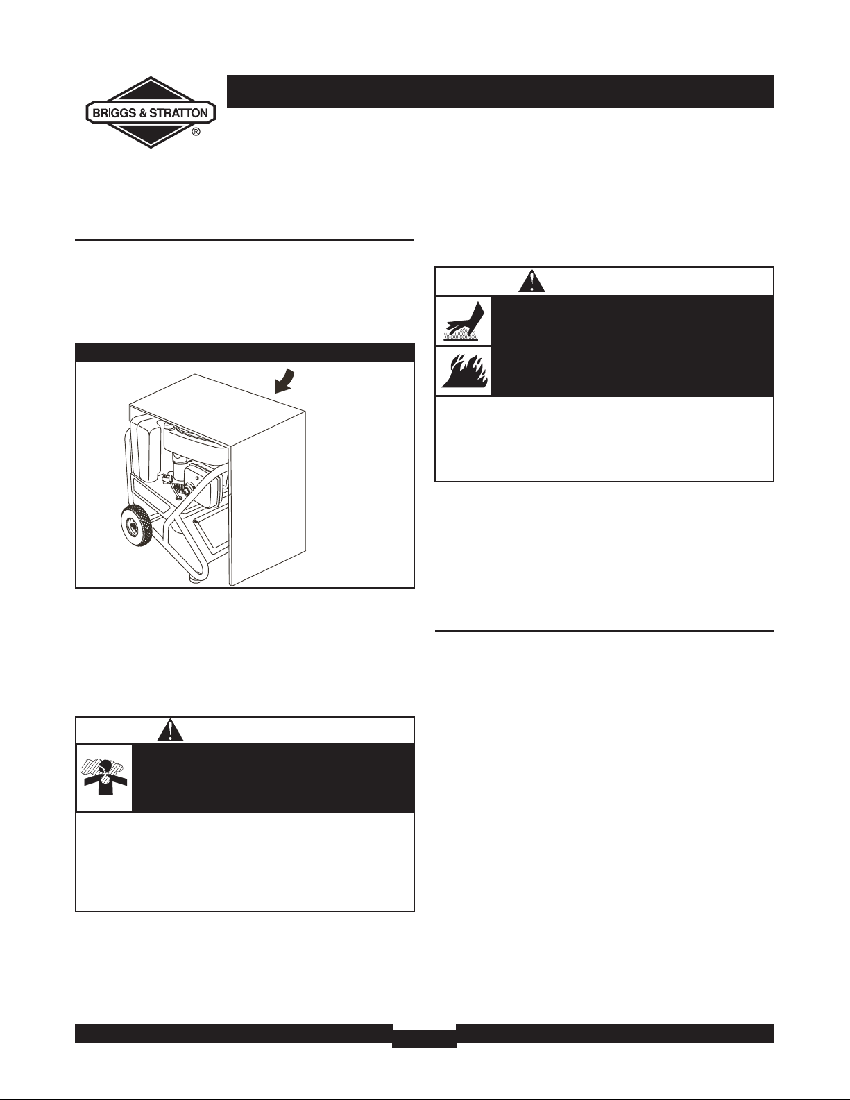
Creating a Temporary Cold Weather
Shelter
1. In an emergency, use the original shipping carton.
2. Cut off top carton flaps and one long side of carton to
expose muffler side of unit. If required, tape up other
sides of carton to fit over generator as shown in
Figure 10.
3. Cut appropriate slots to access receptacles of unit.
4. Face exposed end away from wind and elements.
5. Locate generator as described in the section
“Generator Location”. Keep exhaust gas from entering
a confined area through windows, doors, ventilation
intakes or other openings.
6. Start generator as described in the section “Starting
the Engine”, then place carton over generator. Keep at
least 5 ft. (152 cm) clearance on all sides of generator
including overhead with shelter in place.
7. Remove shelter when temperatures are above 40°F
[4°C].
8. Turn engine OFF and let cool two (2) minutes before
refueling. Let any spilled fuel evaporate before starting
engine.
Creating a Permanent Cold Weather
Shelter
1. Build a structure that will enclose three sides and the
top of the generator, making sure muffler side of
generator is exposed.
NOTE: Structure should hold enough heat created by the
generator to prevent icing problem.
2. DO NOT enclose generator any more than shown in
Figure 10.
3. Follow steps 3 through 8 as described previously in
“Creating a Temporary Cold Weather Shelter”.
Figure 10 — Permanent Cold Weather Shelter
Wind
• Operate generator ONLY outdoors.
• Keep exhaust gas from entering a confined area through
windows, doors, ventilation intakes or other openings.
• DO NOT operate generator inside any building or enclosure
(even if doors or windows are open),including the generator
compartment of a recreational vehicle (RV).
Running generator gives off carbon monoxide,
an odorless, colorless, poison gas.
Breathing carbon monoxide can cause nausea,
fainting or death.
WARNING
• DO NOT touch hot surfaces and avoid hot exhaust gases.
• Allow equipment to cool before touching.
• Keep at least 5 ft. (152 cm) clearance on all sides of generator
including overhead.
• Remove shelter when temperatures are above 40°F [4°C].
Running engines produce heat.Temperature of
muffler and nearby areas can reach or exceed
150°F (65°C).
Severe burns can occur on contact.
Exhaust heat/gases can ignite combustibles,
structures or damage fuel tank causing a fire.
WARNING
Page 13
13
OPERATION
RECEPTACLES
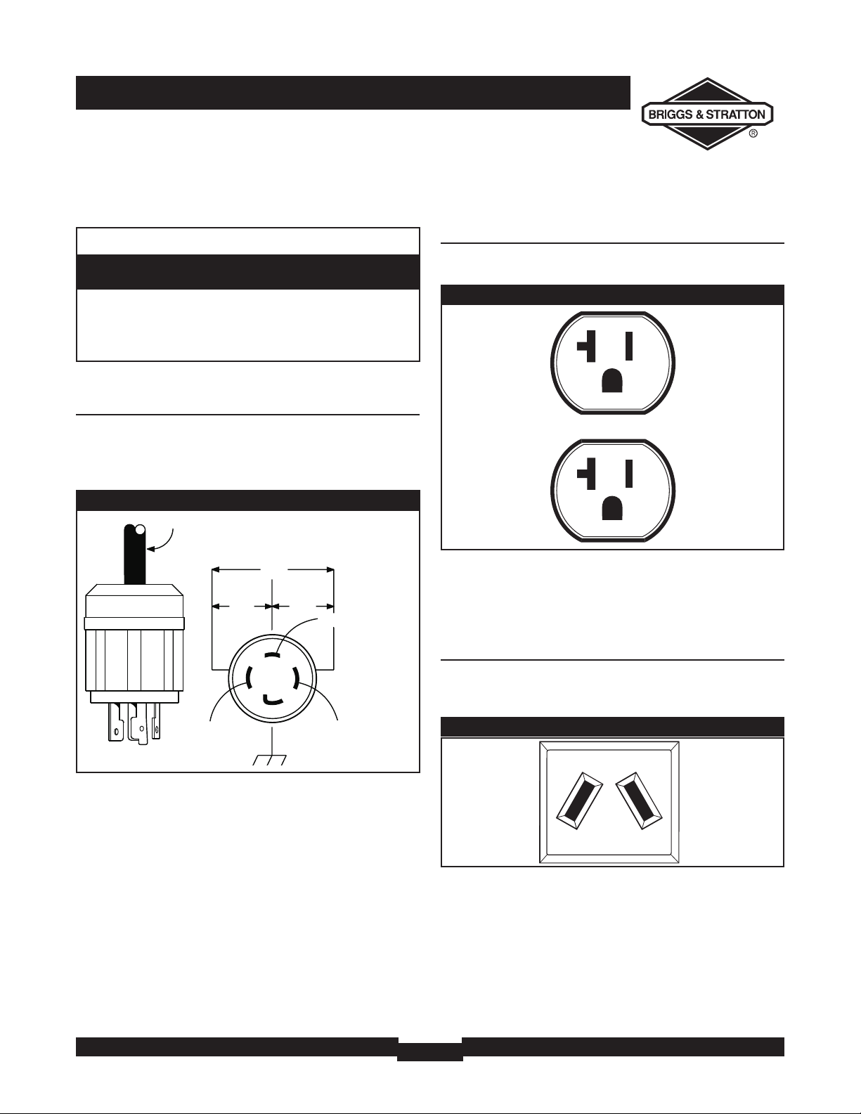
120/240 Volt AC, 30 Amp, Locking
Receptacle
Use a NEMA L14–30 plug with this receptacle. Connect a
4–wire cord set rated for 250 Volt AC loads at 30 Amps (or
greater) (Figure 11).You can use the same 4–wire cord if
you plan to run a 120 Volt load.
This receptacle powers 120/240 Volt AC, 60 Hz, single
phase loads requiring up to 3,500 watts of power at
29.1 Amps for 120 Volts; 7,000 watts of power (7.0 kW) at
29.1 Amps for 240 Volts.The outlet is protected by a
30 Amp rocker switch circuit breaker.
120 Volt AC, 20 Amp, Duplex
Receptacle
Each receptacle (Figure 12) is protected against overload by
a 20 Amp push–to–reset circuit breaker.
Use each receptacle to operate 120 Volt AC, single–phase,
60 Hz electrical loads requiring up to 2,400 watts (2.4 kW)
at 20 Amps of current. Use cord sets that are rated for
125 Volt AC loads at 20 Amps (or greater).
12 Volt DC, 10 Amp Receptacle
This receptacle allows you to recharge a 12 Volt
automotive or utility style storage battery with the battery
charge cables provided (Figure 13).
This receptacle can not recharge 6 Volt batteries and can
not be used to crank an engine having a discharged battery.
See the section “Charging a Battery” (page 10) before
attempting to recharge a battery.
Figure 11 — 120/240 Volt AC, 30 Amp Receptacle
4-Wire Cord Set
240V
120V
120V
W (Neutral)
X (Hot)
Y (Hot)
NEMA L14-30
Ground (Green)
Figure 12 — 120 Volt AC, 20 Amp, Duplex Receptacle
Figure 13 — 12 Volt DC, 10 Amp Receptacle
• NEVER attempt to power a device requiring more amperage
than generator or receptacle can supply.
• DO NOT overload the generator. See “Don’t Overload
Generator”.
Receptacles may be marked with rating value greater
than generator output capacity.
CAUTION
Page 14

OPERATION
14
DON’T OVERLOAD
GENERATOR
Capacity
You must make sure your generator can supply enough
rated (running) and surge (starting) watts for the items you
will power at the same time. Follow these simple steps:
1. Select the items you will power at the same time.
2. Total the rated (running) watts of these items.This is
the amount of power your generator must produce to
keep your items running. See Figure 14.
3. Estimate how many surge (starting) watts you will
need. Surge wattage is the short burst of power
needed to start electric motor-driven tools or
appliances such as a circular saw or refrigerator.
Because not all motors start at the same time, total
surge watts can be estimated by adding only the
item(s) with the highest additional surge watts to the
total rated watts from step 2.
Example:
Total Rated (Running) Watts = 3075
Highest Additional Surge Watts = 1800
Total Generator Output Required = 4875
Power Management
To prolong the life of your generator and attached devices,
it is important to take care when adding electrical loads to
your generator.There should be nothing connected to the
generator outlets before starting its engine.The correct
and safe way to manage generator power is to sequentially
add loads as follows:
1. With nothing connected to the generator, start the
engine as described in this manual.
2. Plug in and turn on the first load, preferably the largest
load you have.
3. Permit the generator output to stabilize (engine runs
smoothly and attached device operates properly.
4. Plug in and turn on the next load.
5. Again, permit the generator to stabilize.
6. Repeat steps 4 and 5 for each additional load.
NEVER add more loads than the generator capacity.Take
special care to consider surge loads in generator capacity,
as described above.
*Wattages listed are approximate only. Check tool or
appliance for actual wattage.
Tool or Appliance
Rated (Running)
Watts
Additional Surge
(Starting) Watts
Window Air
Conditioner
1200 1800
Refrigerator 800 1600
Deep Freezer 500 500
Television 500 Light (75 Watts) 75 -
3075 Total
Running Watts
1800 Highest
Surge Watts
Tool or Appliance
Rated*
(Running)
Watts
Additional
Surge
(Starting)
Watts
Essentials
Light Bulb - 75 watt
75
-
Deep Freezer
500
500
Sump Pump
800
1200
Refrigerator/Freezer - 18 Cu. Ft.
800
1600
Water Well Pump - 1/3 HP
1000
2000
Heating/Cooling
Window AC - 10,000 BTU
1200
1800
Window Fan
300
600
Furnace Fan Blower - 1/2 HP
800
1300
Kitchen
Microwave Oven - 1000 Watt
1000
-
Coffee Maker
1500
-
Electric Stove - Single Element
1500
-
Hot Plate
2500
-
Family Room
DVD/CD Player
100
-
VCR
100
-
Stereo Receiver
450
-
Color Television - 27”
500
-
Personal Computer w/17” monitor
800
-
Other
Security System
180
-
AM/FM Clock Radio
300
-
Garage Door Opener - 1/2 HP
480
520
Electric Water Heater - 40 Gallon
4000
-
DIY/Job Site
Quartz Halogen Work Light
1000
-
Airless Sprayer - 1/3 HP
600
1200
Reciprocating Saw
960
960
Electric Drill - 1/2 HP
1000
1000
Circular Saw - 7 1/4”
1500
1500
Miter Saw - 10”
1800
1800
Table Planer - 6”
1800
1800
Table Saw/Radial Arm Saw - 10”
2000
2000
Air Compressor - 1-1/2 HP
2500
2500
Figure 14 - Wattage Reference Chart
Page 15
15
SPECIFICATIONS & MAINTENANCE
SPECIFICATIONS
Starting Wattage . . . . . . . . . . . . . . . . . . . . 12,250 Watts
Wattage . . . . . . . . . . . . . . . . . . . . . . . . . . . . 7,000 Watts
AC Load Current
At 120 Volts . . . . . . . . . . . . . . . . . . . . . . . 58.3 Amps
At 240 Volts . . . . . . . . . . . . . . . . . . . . . . . 29.1 Amps
Phase . . . . . . . . . . . . . . . . . . . . . . . . . . . . . . . . . . 1-phase
Rated Frequency . . . . . . . . . . . . . . . . . . . . . . . 60 Hertz
Fuel Tank Capacity . . . . . . . . . . . . . . . . . . . 7 U.S. gallons
Shipping Weight. . . . . . . . . . . . . . . . . . . . . . . . . . 230 lbs.
GENERAL MAINTENANCE
RECOMMENDATIONS
The Owner/Operator is responsible for making sure that
all periodic maintenance tasks are completed on a timely
basis; that all discrepancies are corrected; and that the unit
is kept clean and properly stored. NEVER operate a
damaged or defective generator.
NOTE: If equipped with inflatable tires,keep the air pressure
at the value marked on the tire or within 15 and 40 psi.
NOTE: Should you have questions about replacing
components on your BSPP generator, please call
1-800-743-4115 for assistance.
Engine Maintenance
See engine operator’s manual for instructions.
An oil drain tray is provided for your convenience to
change the oil and oil filter. Store tray in a convenient
location for periodic maintenance.
Changing Oil
1. Place the half moon notch in the oil drain tray under
the oil drain plug (Figure 15).
2. Place the oil drain tray foot tab in the slot on the base
of the generator, as shown.
3. Follow the instructions given in the engine operator’s
manual for draining oil.
4. After oil has drained, reinstall the oil drain plug.
5. Remove the oil drain tray from under the oil drain plug
and clean up any spilled oil.
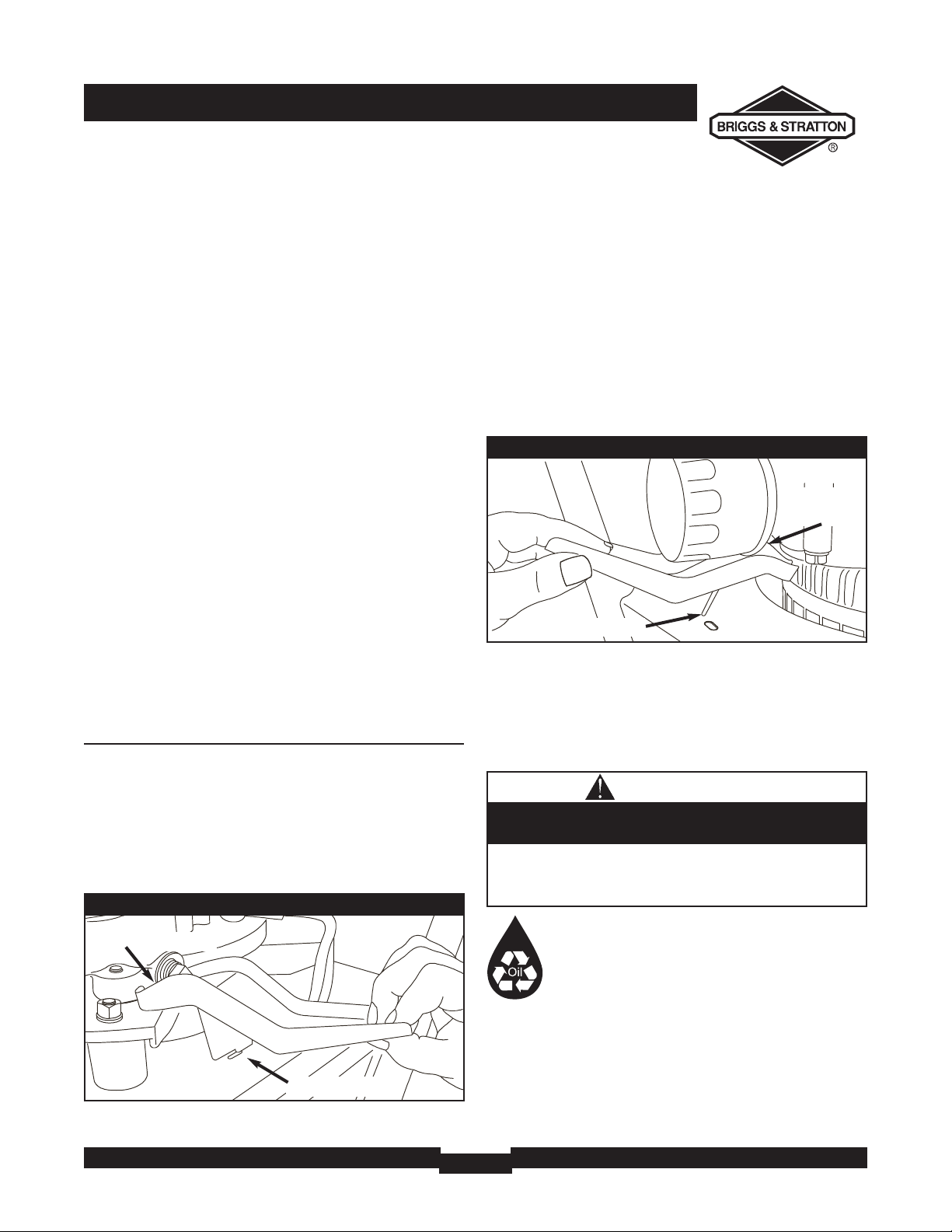
Changing Oil Filter
1. Place the half moon notch in the oil drain tray under
the oil filter (Figure 16).
2. Place the oil drain tray foot tab in the slot on the base
of the generator, as shown.
3. Follow the instructions given in the engine operator’s
manual for changing oil filter and adding oil.
4. Remove the oil drain tray from under the oil filter and
clean up any spilled oil.
KEEP OUT OF REACH OF CHILDREN. DON'T
POLLUTE. CONSERVE RESOURCES. RETURN
USED OIL TO COLLECTION CENTERS.
• Used motor oil has been shown to cause skin cancer in
certain laboratory animals.
• Thoroughly wash exposed areas with soap and water.
Avoid prolonged or repeated skin contact with used
motor oil.
CAUTION
Figure 15 — Changing Oil With Oil Drain Tray
drain tray foot
drain tray notch
Figure 16 — Changing Oil Filter With Oil Drain Tray
drain tray
notch
drain tray foot
Page 16
MAINTENANCE & STORAGE
16
Generator Maintenance
Generator maintenance consists of keeping the unit clean
and dry. Operate and store the unit in a clean dry
environment where it will not be exposed to excessive
dust, dirt, moisture or any corrosive vapors. Cooling air
slots in the generator must not become clogged with snow,
leaves or any other foreign material.
NOTE: DO NOT use a garden hose to clean generator.
Water can enter engine fuel system and cause problems. In
addition, if water enters generator through cooling air slots,
some of the water will be retained in voids and cracks of
the rotor and stator winding insulation.Water and dirt
buildup on the generator internal windings will eventually
decrease the insulation resistance of these windings.
Battery Maintenance
Other than float charging, as described in “How to Use the
Battery Charger”, no maintenance is required for the
battery. Keep the battery and terminals clean and dry.
IMPORTANT: Battery charging should be performed in a
dry location, such as inside a garage.
Generator Cleaning
• Use a damp cloth to wipe exterior surfaces clean.
• Use a soft bristle brush to loosen caked on dirt or oil.
• Use a vacuum cleaner to pick up loose dirt and debris.
• Inspect cooling air slots and opening on generator.These
openings must be kept clean and unobstructed.
STORAGE
The generator should be started at least once every seven
days and allowed to run at least 30 minutes. If this cannot
be done and you must store the unit for more than
30 days, use the following guidelines to prepare it for
storage.
Generator Storage
• Clean the generator as outlined in “Generator Cleaning”.
• Check that cooling air slots and openings on generator
are open and unobstructed.
Engine Storage
See engine operator’s manual for instructions.
Other Storage Tips
• To prevent gum from forming in fuel system or on
essential carburetor parts, add fuel stabilizer into fuel
tank and fill with fresh fuel. Run the unit for several
minutes to circulate the additive through the carburetor.
The unit and fuel can then be stored for up to
24 months. Fuel stabilizer can be purchased locally.
• DO NOT store fuel from one season to another unless
it has been treated as described above.
• Replace fuel container if it starts to rust. Rust and/or dirt
in fuel can cause problems if it's used with this unit.
• Store unit in a clean and dry area.
• DO NOT expose generator to excessive moisture, dust, dirt,
or corrosive vapors.
• DO NOT insert any objects through cooling slots.
Improper treatment of generator can damage it and
shorten its life.
CAUTION
WHEN ADJUSTING OR MAKING REPAIRS TO YOUR
GENERATOR
• Disconnect the spark plug wire from the spark plug and place
the wire where it cannot contact spark plug.
WHEN TESTING FOR ENGINE SPARK
• Use approved spark plug tester.
• DO NOT check for spark with spark plug removed.
Unintentional sparking can result in fire or
electric shock.
WARNING
• DO NOT place a storage cover over a hot generator.
• Let equipment cool for a sufficient time before placing the
cover on the equipment.
Storage covers can be flammable.
WARNING
Page 17

17
TROUBLESHOOTING
TROUBLESHOOTING
Problem Cause Correction
No AC output is available, but
generator is running.
1. One of the circuit breakers is
open.
2. Fault in generator.
3. Poor connection or defective cord
set.
4. Connected device is bad.
1. Reset circuit breaker.
2. Contact Authorized service facility.
3. Check and repair.
4. Connect another device that is in
good condition.
Generator runs good at no-load
but "bogs" down" when loads are
connected.
1. Short circuit in a connected load.
2. Generator is overloaded.
3. Shorted generator circuit.
1. Disconnect shorted electrical load.
2. See "Don't Overload Generator".
3. Contact Authorized service facility.
Generator will not start; or starts
and runs rough.
1. 10 Amp in-line fuse is blown.
2. Discharged battery.
3. Failed battery.
4. Low oil level.
1. Replace fuse.
2. Jump start generator and/or charge
battery.
3. Replace battery.
4. Fill crankcase to proper level or
place generator on level surface.
Generator shuts down during
operation.
Out of gasoline. Fill fuel tank.
Generator lacks power. Load is too high. See "Don't Overload Generator".
Page 18

NOTES
18
NOTES
Page 19

BRIGGS & STRATTON POWER PRODUCTS GROUP, LLC PORTABLE GENERATOR OWNER WARRANTY POLICY
LIMITED WARRANTY
Briggs & Stratton Power Products Group, LLC will repair or replace, free of charge, any part(s) of the portable generator that is
defective in material or workmanship or both. Transportation charges on product submitted for repair or replacement under this
warranty must be borne by purchaser. This warranty is effective for the time periods and subject to the conditions stated below.
For warranty service, find the nearest Authorized Service Dealer in our dealer locator map at www.briggspowerproducts.com.
THERE IS NO OTHER EXPRESS WARRANTY. IMPLIED WARRANTIES, INCLUDING THOSE OF MERCHANTABILITY AND
FITNESS FOR A PARTICULAR PURPOSE, ARE LIMITED TO ONE YEAR FROM PURCHASE, OR TO THE EXTENT
PERMITTED BY LAW ANY AND ALL IMPLIED WARRANTIES ARE EXCLUDED. LIABILITY FOR INCIDENTAL OR
CONSEQUENTIAL DAMAGES ARE EXCLUDED TO THE EXTENT EXCLUSION IS PERMITTED BY LAW. Some states or
countries do not allow limitations on how long an implied warranty lasts, and some states or countries do not allow the
exclusion or limitation of incidental or consequential damages, so the above limitation and exclusion may not apply to you. This
warranty gives you specific legal rights and you may also have other rights which vary from state to state or country to country.
2 years*
1 year
Consumer Use
Commercial Use
The warranty period begins on the date of purchase by the first retail end user, and continues for the period of time stated above.
“Consumer Use" means personal residential household use by a retail consumer. “Commercial Use" means all other uses, including
use for commercial, income producing or rental purposes. Once equipment has experienced commercial use, it shall thereafter be
considered as commercial use for purposes of this warranty.
NO WARRANTY REGISTRATION IS NECESSARY TO OBTAIN WARRANTY ON BRIGGS & STRATTON PRODUCTS. SAVE
YOUR PROOF OF PURCHASE RECEIPT. IF YOU DO NOT PROVIDE PROOF OF THE INITIAL PURCHASE DATE AT THE TIME
WARRANTY SERVICE IS REQUESTED, THE MANUFACTURING DATE OF THE PRODUCT WILL BE USED TO DETERMINE
THE WARRANTY PERIOD.
ABOUT YOUR WARRANTY
We welcome warranty repair and apologize to you for being inconvenienced. Any Authorized Service Dealer may perform warranty
repairs. Most warranty repairs are handled routinely, but sometimes requests for warranty service may not be appropriate. For
example, warranty service would not apply if equipment damage occurred because of misuse, lack of routine maintenance,
shipping, handling, warehousing or improper installation. Similarly, the warranty is void if the manufacturing date or the serial number
on the portable generator has been removed or the equipment has been altered or modified. During the warranty period, the
Authorized Service Dealer, at its option, will repair or replace any part that, upon examination, is found to be defective under normal
use and service. This warranty will not cover the following repairs and equipment:
• Normal Wear: Outdoor Power Equipment, like all mechanical devices, needs periodic parts and service to perform well. This
warranty does not cover repair when normal use has exhausted the life of a part or the equipment.
• Installation and Maintenance: This warranty does not apply to equipment or parts that have been subjected to improper or
unauthorized installation or alteration and modification, misuse, negligence, accident, overloading, overspeeding, improper
maintenance, repair or storage so as, in our judgment, to adversely affect its performance and reliability. This warranty also does
not cover normal maintenance such as air filters, adjustments, fuel system cleaning and obstruction (due to chemical, dirt,
carbon, lime, and so forth).
• Other Exclusions: This warranty excludes wear items such as o-rings, filters, etc., or malfunctions resulting from accidents,
abuse, modifications, alterations, or improper servicing or freezing or chemical deterioration. Accessory parts such as generator
adapter cord sets and storage covers are excluded from the product warranty. This warranty excludes used, reconditioned, and
demonstration equipment, equipment used for prime power in place of utility power, equipment used in life support applications,
and failures due to acts of God and other force majeure events beyond the manufacturers control.
BRIGGS & STRATTON POWER PRODUCTS GROUP, LLC
JEFFERSON, WI, USA
Effective February 1, 2006 replaces all undated Warranties and all Warranties dated before February 1, 2006
198189E, Rev 0. 02/01/2006
*Second year parts only
WARRANTY PERIOD
Page 20

RÈGLES DE SÉCURITÉ
20
TABLE DES MATIÈRES
Règles de Sécurité . . . . . . . . . . . . . . . . . . . . . . . . . . . . . . . . . . 20-22
Connaissez Votre Générateur . . . . . . . . . . . . . . . . . . . . . . . . . . . 23
Assemblage . . . . . . . . . . . . . . . . . . . . . . . . . . . . . . . . . . . . . . . 24-25
Opération . . . . . . . . . . . . . . . . . . . . . . . . . . . . . . . . . . . . . . . . 26-32
Entretien . . . . . . . . . . . . . . . . . . . . . . . . . . . . . . . . . . . . . . . . . 33-34
Rangement . . . . . . . . . . . . . . . . . . . . . . . . . . . . . . . . . . . . . . . . . . 34
Remarques . . . . . . . . . . . . . . . . . . . . . . . . . . . . . . . . . . . . . . . . . . 35
Dépannage . . . . . . . . . . . . . . . . . . . . . . . . . . . . . . . . . . . . . . . . . . 36
Garantie . . . . . . . . . . . . . . . . . . . . . . . . . . . . . . . . . . . . . . . . . . . . 37
DESCRIPTION DE L ÉQUIPEMENT
Lisez avec soin ce manuel et familiarisez-vous avec
votre générateur. Connaissez ses applications, ses
limitations et les dangers qu'il implique.
Ce générateur est un générateur entraîné par un moteur à champ
magnétique rotatif produisant du courant alternatif (c.a.). Il a été
conçu pour fournir du courant électrique pour faire marcher des
charges compatibles d'éclairage, d'appareils ménagers, d'outil et de
moteur. Le champ tournant du générateur est entraîné à
3,600 T/M par un moteur seul cylindrique.
ATTENTION! NE PAS dépasser la capacité en watts ou en
Ampères du générateur.Voir "Ne Pas Surcharger Générateur"
pour l'information spécifique.
Tout a été mis en oeuvre pour que les informations contenues
dans ce manuel soient exactes et à jour. Cependant, nous se
réserve le droit de changer, d'altérer ou d'améliorer le produit à
n'importe quel moment sans avis préalable.
Le Système de contrôle de l'émission du générateur est garanti
pour des normes établies par L'Agence de protection de
l'environnement et le California Air Resources Board. Pour des
informations sur la garantie, se reporter au manuel d'utilisation du
moteur.
RÈGLES DE SÉCURITÉ
Ceci est la sûreté le symbole vif. Il est utilisé pour
vous alerter aux dangers de blessure personnels
potentiels. Obéir tous messages de sûreté qui suivent
ce symbole éviter la blessure ou la mort possibles.
Le symbole indiquant un message de sécurité est accompagné d'un
mot indicateur (DANGER,ATTENTION,AVERTISSEMENT),d'un
message illustré et/ou d'un message de sécurité visant à vous
avertir des dangers.DANGER indique un danger qui, s'il n'est pas
évité, provoquera des blessures graves,voire fatales.
AVERTISSEMENT indique un danger qui,s'il n'est pas évité, peut
provoquer des blessures graves,voire fatales. ATTENTION
indique un danger qui, s'il n'est pas évité, peut provoquer des
blessures mineures ou légères.Le mot ATTENTION, lorsqu'il est
utilisé sans le symbole d'alerte, indique une situation pouvant
endommager l'équipement. Suivez les messages de sécurité pour
éviter ou réduire les risques de blessures ou de mort.
Symboles de Danger et Moyens
L’échappement du moteur de ce produit contient des produits
chimiques que l’État de Californie considère comme causant le
cancer, des déformations à la naissance ou d’autres dangers
concernant la reproduction.
AVERTISSEMENT
Feu
Explosion
Emanations Toxiques
Surface Chaude
Manuel d'Utilisation
Choc Électrique
Pression Explosive
Brûlures Chimiques
VEUILLEZ CONSERVER CES INSTRUCTIONS
Page 21

21
RÈGLES DE SÉCURITÉ
LORS DE L'AJOUT OU DE LA VIDANGE DU
CARBURANT
• Éteignez le générateur et laissez-le refroidir au moins 2 minutes avant
de retirer le capuchon du réservoir de carburant. Desserrez lentement
le capuchon pour laisser la pression s'échapper du réservoir.
• Remplissez ou vidangez le réservoir d'essence à l'extérieur.
• NE REMPLISSEZ PAS trop le réservoir. Laissez 2.25 pouce pour
l'expansion de l'essence.
• Si du carburant est renversé, attendez qu'il s'évapore avant de
démarrer le moteur.
• Éloignez l'essence des étincelles, des flammes, des veilleuses, de la
chaleur et de toute autre source d'inflammation.
• N'ALLUMEZ PAS de cigarette ou ne fumez pas à proximité de l'appareil.
LORS DU DÉMARRAGE DE L'ÉQUIPEMENT
• Assurez-vous que la bougie d'allumage, le silencieux, le bouchon à
essence et le filtre à air sont en place.
• NE démarrez PAS le moteur lorsque la bougie d'allumage est enlevée.
LORSQUE L'ÉQUIPEMENT FONCTIONNE
• NE penchez PAS le moteur ou l'équipement,vous risqueriez de
renverser de l'essence.
• Cette génératrice n'est pas conçue pour être utilisée dans de
l'équipement mobile ou les applications marines.
LORSQUE VOUS TRANSPORTEZ OU RÉPAREZ
L'ÉQUIPEMENT
• Le réservoir d'essence doit être VIDE ou le robinet d'arrêt de
carburant doit être à la position fermée (OFF) pendant le transport
ou la réparation.
• Débranchez le câble de bougie.
LORSQUE VOUS ENTREPOSEZ L'ESSENCE OU UN
ÉQUIPEMENT AVEC UN RÉSERVOIR À ESSENCE
• Entreposez-le loin des appareils de chauffage, des fours, des chauffeeau, des sécheuses ou de tout autre appareil électroménager
disposant d'une veilleuse ou de toute autre source d'inflammation
risquant d'enflammer les vapeurs d'essence.
L'essence et ses vapeurs sont extrêmement
inflammables et explosives.
Le feu ou l'explosion risque de provoquer des
blessures graves,pouvant être fatales.
AVERTISSEMENT
• Ne laissez aucune flamme, étincelle, source de chaleur ou cigarette
allumée pendant ou plusieurs minutes suivant la charge de
l'accumulateur.
• Portez des lunettes de protection, un tablier et des gants en caoutchouc.
Les batteries d'accumulateur produisent du gaz
hydrogène explosif lorsqu'elles se rechargent.
Le gaz hydrogène stagne autour de la batterie
longtemps après qu'elle ait été chargée.
La plus petite étincelle enflammera l'hydrogène et
provoquera une explosion.
Vous pouvez devenir aveugle ou vous blesser gravement.
Le liquide d'électrolyte de l'accumulateur contient de
l'acide et est extrêmement caustique.
Le contact avec le liquide de l'accumulateur
provoquera de graves brûlures chimiques.
DANGER
• Cette génératrice ne satisfait pas aux normes U. S. Coast Guard
Regulation 33CFR-183 et ne doit pas être utilisée pour des
applications marines.
• L'omission d'utiliser une génératrice appropriée et approuvée par U. S.
Coast Guard pourrait entraîner des blessures corporelles ou des
dommages matériels.
AVERTISSEMENT
• Faites fonctionner le générateur SEULEMENT à l'extérieur.
• Évitez que les gaz d'échappement entrent dans un espace restreint,
par une fenêtre, une porte, une prise d'aération ou toute autre
ouverture.
• NE FAITES PAS fonctionner le générateur à l'intérieur d'un bâtiment
ou d'un abri (même si les portes ou les fenêtres sont ouvertes), y
compris à l'intérieur du compartiment d'un véhicule de plaisance.
Le générateur, lorsqu'il fonctionne, produit du monoxyde
de carbone, un gaz toxique inodore et incolore.
Le fait de respirer du monoxyde de carbone provoque
des nausées, des évanouissements ou peut être fatal.
AVERTISSEMENT
• Lorsque vous utilisez le générateur comme source d'énergie de
secours, il est nécessaire d'aviser les services publics d'électricité.
• Utilisez un disjoncteur différentiel lorsque vous utilisez l'appareil dans
des endroits humides ou extrêmement conductibles, comme les
terrasses en métal ou les ouvrages métalliques.
• NE touchez pas les fils dénudés ou les boîtiers.
• N'UTILISEZ pas le générateur avec des cordons électriques usés,
effilochés ou dénudés, ou abîmés de quelque sorte que ce soit.
• N'UTILISEZ pas le générateur sous la pluie.
• NE manipulez pas le générateur ou les cordons d'alimentation lorsque
vous êtes debout dans l'eau, pieds nus ou avec les mains ou les pieds
humides.
• NE laissez pas des personnes non qualifiées ou des enfants se servir
ou réparer le générateur.
Le générateur produit une tension élevée.
Ne pas isoler le générateur de l'installation électrique
risque de provoquer des blessures ou même d'être fatal
pour les ouvriers électriciens et de causer des dommages
au générateur dus à un "backfeed" d'énergie électrique.
AVERTISSEMENT
Page 22

RÈGLES DE SÉCURITÉ
22
• NE TRAFIQUEZ PAS la vitesse régulée. Le générateur produit une
fréquence nominale et une tension correctes lorsqu'il fonctionne à
une vitesse régulée.
• NE modifiez le générateur d'aucune façon.
Les vitesses de fonctionnement excessivement élevées
augmentent les risques de blessure ou risquent d'endommager
le générateur.
Les vitesses extrêmement lentes entraînent une charge importante.
ATTENTION
• Voir la section " Ne Pas Surcharger Générateur ".
• Démarrez le générateur et laissez le moteur se stabiliser avant de
brancher les charges électriques.
• Branchez les charges électriques en position ARRÊT, puis, remettez en
position MARCHE.
• Éteignez les charges électriques et débranchez-les du générateur avant
de l'arrêter.
Dépasser la capacité de puissance ou d'ampérage du
générateur risque d'endommager ce dernier et/ou les autres
appareils électriques qui y sont branchés.
ATTENTION
• NE vous servez du générateur que pour les utilisations prévues.
• Si vous avez des questions concernant les utilisations prévues,
demandez à votre distributeur ou appelez 1-800-743-4115.
• Ne faites fonctionner le générateur que sur des surfaces horizontales.
• N'EXPOSEZ pas le générateur à une humidité excessive, à de la
poussière, à de la saleté ou à des vapeurs corrosives.
• N'INSÉREZ aucun objet dans les fentes de refroidissement.
• Si les appareils branchés sont en surchauffe, éteignez-les et
débranchez-les du générateur.
• Arrêtez le générateur si :
-la puissance électrique est inexistante;
-l'équipement produit des étincelles, de la fumée ou des flammes;
-l'unité vibre excessivement.
Un traitement inapproprié du générateur risque de
l'endommager et de raccourcir sa durée d'utilisation.
ATTENTION
LORSQUE VOUS RÉGLEZ OU RÉPAREZ VOTRE
GÉNÉRATEUR
• Débranchez toujours le câble de bougie et placez-le de façon à ce
qu'il ne soit pas en contact avec la bougie.
LORS DE TESTS D'ALLUMAGE DU MOTEUR
• Utilisez un vérificateur de bougies d'allumage approuvé.
• NE vérifiez PAS l'allumage lorsque la bougie d'allumage est enlevée.
Unintentional peut résulter dans feu ou électrique.
AVERTISSEMENT
• NE TOUCHEZ PAS aux pièces chaudes et évitez le contact avec les
gaz d’échappement.
• Laissez l'équipement refroidir avant de le toucher.
• Laissez un dégagement d’au moins 1,52 m (5 pi) tout autour de la
génératrice, y compris au-dessus.
• Le Code of Federal Regulation (CFR) Title 36 Parks, Forests,and Public
Property exige que de l’équipement alimenté par un moteur à
combustion interne soit doté d’un pare-étincelles et constamment
maintenu en bon état fonctionnement, conformément à la norme de
service 5100-1C de la USDA Forest ou à une révision de celle-ci.Dans
l’État de la Californie, un pare-étincelles est requis en vertu de la section
4442 du California Public Resources Code. Il se peut que d’autres États
aient des lois semblables.aux terres fédérales. Si vous équipez le silencieux
d'un pare-étincelles, il doit être en bon état de fonctionnement.
Les moteurs en fonctionnement produisent de la
chaleur. La température du silencieux et des endroits
à proximité peuvent atteindre, voire dépasser 150°F
(65°C).
Le contact de ces pièces risque de causer de graves
brûlures.
La chaleur et les gaz d’échappement peuvent
enflammer des matériaux combustibles et les
structures ainsi que causer des dommages au
réservoir d’essence et entraîner un incendie.
AVERTISSEMENT
Page 23

23
CONNAISSEZ VOTRE GÉNÉRATEUR
CONNAISSEZ VOTRE GÉNÉRATEUR
Lire ce manuel de l'utilisateur et les régles de sécurité avant de faire marcher votre générateur.
Comparez les illustrations avec votre générateur pour vous familiariser avec l'emplacement des diverses commandes et réglages.
Gardez ce manuel pour le consulter plus tard.
Batterie - Localisé sous la porte en matière plastique. Batterie scellée
de 12 Volts C.C., fournissant l'énergie pour démarrer le moteur.
Bouton Démarrer - Appuyez et le moteur se met en marche.
Bouchon de remplissage d'huile - Ajoutez de l'huile au
moteur à cet endroit.
Disjoncteurs (c.a.) - Chaque prise est dotée d'un disjoncteur
pour protéger le générateur contre les surcharges électriques.Les
disjoncteurs sont du genre "pousser pour reconfigurer".
Disjoncteur avec interrupteur à bascule - La prise
verrouillable de 120/240 volts c.a., 30 ampères, est munie d'un
disjoncteur avec interrupteur à levier pour protéger la génératrice
contre les surcharges.
Données Étiquettent - Fournit le modèle, la révision et le
numéro de série de générateur. S'il vous plaît avoir ces facilement
disponible si appeler l'assistance.
Filtre à air – Utilise un élément de filtre du type sec et un préfiltre en mousse pour limiter le montant de saleté et de
poussières entrant dans le moteur.
Fixation de mise à la masse — Consultez l’agence compétente
de votre région au sujet des exigences de mise à la masse.
Interrupteur de starter – Utilisé lorsque vous faites un
démarrage à froid du moteur.
Pot d’échappement avec arrêteur d’étincelles – Le pot
d’échappement diminue le bruit du moteur est équipé d’un écran
arrêteur d’étincelles.
Prise de 12 Volts 10 Ampères c.c. – Cette prise vous permet
de recharger une batterie automobile de 12 Volts.
Prises de courant double de 120 Volts c.a., 20 Ampères -
peuvent être utilisées pour fournir l'alimentation électrique de
l'éclairage, des électroménagers, des outils ou des moteurs de
120 Volts, 20 Ampères,monophasés, 60 Hz.
Prise de 120/240 Volts c.a., 30 Ampères – Peut être utilisée
pour fournir du courant électrique pour faire marcher des
systèmes d’éclairage, des appareils, des outils ou des moteurs
nécessitant 120 Volts et/ou 240 Volts c.a., 30 Ampères,
monophasés, 60 Hertz.
Réservoir de carburant – Capacité de 7 gallons Etats-Unis.
Interrupteur de
starter
Disjoncteurs (c.a)
Disjoncteur avec
interrupteur à bascule
Prise de courant
double de120 Volts
c.a., 20 Ampères
Prise de 120/240 Volts,
30 Ampères, c.a.
Batterie
Prise de 12 Volts,
10 Ampères, c.c.
Pot d’échappement avec
arrêteur d’étincelles
Bouton Démarrer
Fixation de mise à la masse
Filtre à air
Réservoir de carburant
Bouchon de remplissage d'huile
Données Étiquettent
Page 24

ASSEMBLAGE
24
ASSEMBLAGE
Votre générateur exige que quelque assemblée et soit prêt pour
l'usage après il a été convenablement entretenu avec le pétrole et
le carburant recommandés.
Si vous avez n'importe quels problèmes avec l'assemblée
de votre générateur, s'il vous plaît appeler le helpline de
générateur à 1-800-743-4115. Si vous téléphonez pour obtenir
de l'aide, veuillez avoir disponibles les renseignements du données
étiquettent: numéro de modèle, de révision et de série. Consultez
la section “Connaissez Votre Générateur” pour déterminer son
emplacement.
Enlever le génératrice de la boite
1. Placez la boîte de carton sur une surface plane rigide.
2. Ouvrez la boîte d’expédition en coupant tous les coins du
haut vers le bas.
3. Enlever tout matériel qui emballe, fillers de boîte, etc.
4. Enlever le générateur de la boîte qui expédie.
Fixer la poignée
Vous avez besoin de deux clés de 13 mm et 1/2” pour fixer la poignée.
1. Fixez la poignée à la partie de droite du cadre de la
génératrice (en regardant l'unité de face),tel que montré à la
Figure 17, à l'aide des 60 mm vis, des rondelles,des rondelles
de nylon et des écrous.
REMARQUE: NE serrez PAS trop fort. La poignée doit pouvoir
être déplacée librement vers le haut et vers le bas.
2. Levez la poignée et insérez la tige de la poignée pour déplacer
la génératrice.
60 mm vis
écrou
rondelles
tige de la poignée
rondelles de Nylon
Figure 17 — Fixer la Poignée
écrou
rondelles
rondelles de nylon
rondelles de nylon
rondelles
60 mm vis
tige de la poignée
poignée parenthèse
poignée parenthèse
Page 25

25
ASSEMBLAGE
AVANT LE DÉMARRAGE DU
MOTEUR
Ajoutez de l'huile à moteur
• Mettre le génératrice sur une surface à niveau.
• Reportez-vous au manuel d'utilisation du moteur et suivez les
directives et les recommandations relatives à l'huile.
REMARQUE: Vérifiez souvent l'huile lors du rodage du moteur.
Consultez les recommandations contenues dans le manuel
d'utilisation du moteur.
REMARQUE: Le champ tournant du générateur est porté par
un roulement à billes pré-lubrifié et scellé qui ne nécessite aucune
lubrification supplémentaire pendant toute la durée de vie du
roulement.
Ajoutez de l'essence
REMARQUE: Le fonctionnement avec de l'essence est certifié
avec ce moteur à essence. Dispositif antipollution de
l'échappement: EM (Modifications de moteur).
1. Utilisez de l'essence sans plomb ordinaire propre et fraîche
avec un indice d'octane d'au moins 87.N'utilisez PAS de
carburant qui contient du Méthanol. NE mélangez PAS avec
de l'huile.
2. Nettoyez la partie autour du bouchon du réservoir d'essence,
enlevez le bouchon.
3. Ajoutez lentement de l'essence sans plomb ordinaire dans le
réservoir d'essence. Faites attention pour ne pas trop remplir.
Laissez environ 6 cm (2.25") d'espace de réservoir pour
l'expansion du carburant (Figure 18).
4. Installez le bouchon à essence et attend le carburant renversé
pour s'évaporer.
Enlevez le couvercle de l'interrupteur de
démarrage
Un couvercle de plastique est placé sur l'interrupteur de
démarrage afin d'empêcher le démarrage de la génératrice.
• La casquette ouverte sur la chargeur de flotteur pour que la
batterie.
• Enlevez et jetez le couvercle de plastique sur l'interrupteur de
démarrage (Figure 19).
• Remplacer la chargeur de flotteur pour que la batterie.
• Reportez-vous au manuel d'utilisation du moteur au sujet de l'huile et
du combustible.
• La garantie sera annulée si des dommages à l'équipement sont
entraînés par le manquement à se conformer à cette directive.
Toute tentative de démarrer le moteur sans qu'il ait été rempli
avec l'huile recommandée entraînera une panne de l'équipement.
ATTENTION
Essence
Résevoir
Espace d'air 2.25"
Figure 18 - d'Espace de Réservoir
LORS DE L'AJOUT DU CARBURANT
• Éteignez le générateur et laissez-le refroidir au moins 2 minutes avant
de retirer le capuchon du réservoir de carburant. Desserrez lentement
le capuchon pour laisser la pression s'échapper du réservoir.
• Remplissez le réservoir d'essence à l'extérieur.
• NE REMPLISSEZ PAS trop le réservoir. Laissez 2.25 pouce pour
l'expansion de l'essence.
• Attend le carburant renversé pour s'évaporer avant de démarrer le
moteur.
• Éloignez l'essence des étincelles, des flammes, des veilleuses, de la
chaleur et de toute autre source d'inflammation.
• N'ALLUMEZ PAS de cigarette ou ne fumez pas à proximité de l'appareil.
L'essence et ses vapeurs sont extrêmement
inflammables et explosives.
Le feu ou l'explosion risque de provoquer des
blessures graves,pouvant être fatales.
AVERTISSEMENT
Figure 19 — l'Interrupteur de Démarrage
• Dans le manuel d'utilisation du moteur, remplacez "3,8 cm (1,5 po)"
par "5,7 cm (2,25 po)" comme limite de remplissage du réservoir à
carburant.
• L'omission de suivre ces instructions pourrait entraîner l'expansion
excessive et le déversement du carburant du réservoir.
Remplissez le réservoir jusqu'à environ 5,7 cm
(2,25 po) au-dessous du haut du goulot de
remplissage afin de laisser de l'espace pour
l'expansion du combustible.
AVERTISSEMENT
Page 26

OPÉRATION
26
UTILISATION DE LA
GÉNÉRATRICE
Mise à la terre du système
La génératrice possède une mise à la terre du système qui
raccorde les éléments du cadre de la génératrice aux bornes de
mise à la terre des prises de sortie C.A. La mise à la terre du
système est raccordée au fil neutre C.A..
Exigences spéciales
Il se peut que la réglementation d'une agence fédérale ou
provinciale de santé et de sécurité du travail,des codes de
sécurité nationaux ou provinciaux ou des ordonnances régissent
l'utilisation prévue de la génératrice.Veuillez consulter un
électricien qualifié, un inspecteur en électricité ou l'agence
compétente de votre région.
• Dans certains territoires, il faut enregistrer la génératrice
auprès du fournisseur de l'alimentation de service.
• Des règlements additionnels régissent peut-être l'utilisation de
la génératrice sur les chantiers de construction.
Branchement au système électrique d'un
édifice
Seuls les électriciens qualifiés sont habilités à brancher la
génératrice au système électrique d'un édifice pour en faire une
source d'alimentation de réserve. Il faut que l'alimentation de la
génératrice soit isolée de l'alimentation de service et que le
branchement soit conforme à toute la législation applicable et à
tous les codes de l'électricité.
Emplacement de la Génératrice
Dégagement de la génératrice
Placez la génératrice dans un endroit bien ventilé qui permet
l'élimination des gaz d'échappement mortels. N'installez pas la
génératrice dans un endroit où les gaz d'échappement pourraient
s'accumuler et pénétrer ou être aspirés dans un édifice qui
pourrait être occupé.Assurez-vous que les gaz d'échappement ne
puissent entrer par une fenêtre, une porte, une prise d'aération
ou une autre ouverture qui pourrait leur permettre de
s'accumuler dans un espace restreint (Figure 20).Tenez aussi
compte des vents dominants et des courants d'air au moment de
choisir l'endroit où vous installerez la génératrice.
• Lorsque vous utilisez le générateur comme source d'énergie de
secours, il est nécessaire d'aviser les services publics d'électricité.
• Utilisez un disjoncteur différentiel lorsque vous utilisez l'appareil dans
des endroits humides ou extrêmement conductibles, comme les
terrasses en métal ou les ouvrages métalliques.
• NE touchez pas les fils dénudés ou les boîtiers.
• N'UTILISEZ pas le générateur avec des cordons électriques usés,
effilochés ou dénudés, ou abîmés de quelque sorte que ce soit.
• N'UTILISEZ pas le générateur sous la pluie.
• NE manipulez pas le générateur ou les cordons d'alimentation lorsque
vous êtes debout dans l'eau, pieds nus ou avec les mains ou les pieds
humides.
• NE laissez pas des personnes non qualifiées ou des enfants se servir
ou réparer le générateur.
Le générateur produit une tension élevée.
Ne pas isoler le générateur de l'installation électrique
risque de provoquer des blessures ou même d'être fatal
pour les ouvriers électriciens et de causer des dommages
au générateur dus à un "backfeed" d'énergie électrique.
AVERTISSEMENT
Figure 20 — Dégagement de la génératrice
Orifice d'échappement
• Faites fonctionner le générateur SEULEMENT à l'extérieur.
• Évitez que les gaz d'échappement entrent dans un espace restreint,
par une fenêtre, une porte, une prise d'aération ou toute autre
ouverture.
• NE FAITES PAS fonctionner le générateur à l'intérieur d'un bâtiment
ou d'un abri (même si les fenêtres et les portes sont ouvertes), y
compris à l'intérieur du compartiment d'un véhicule de plaisance.
Le générateur, lorsqu'il fonctionne, produit du monoxyde
de carbone, un gaz toxique inodore et incolore.
Le fait de respirer du monoxyde de carbone provoque
des nausées, des évanouissements ou peut être fatal.
AVERTISSEMENT
• Laissez un dégagement d’au moins 1,52 m (5 pi) tout autour de la
génératrice, y compris au-dessus.
La chaleur et les gaz d’échappement peuvent
enflammer des matériaux combustibles et les
structures ainsi que causer des dommages au
réservoir d’essence et entraîner un incendie.
AVERTISSEMENT
Page 27

27
OPÉRATION
UTILISATION DU GÉNÉRATEUR
Démarrage du Moteur
IMPORTANT: Débranchez toujours le chargeur de flotteur de la
batterie avant de démarrer le générateur.
Déconnectez toutes les charges électriques du générateur. Suivez
ces étapes d'instructions de démarrage dans l'ordre numérique:
1. Assurez-vous que la génératrice se trouve sur une surface de
niveau.
IMPORTANT: Si la génératrice n'est pas sur une surface de
niveau, elle pourrait ne pas démarrer ou encore s'arrêter
spontanément.
2. Suivre les instructions de début données dans le manuel de
moteur et tournez l'interrupteur de démarrage situé sur la
génératrice à la position "Start" (Figure 21).
Afin de prolonger la durée de vie utile des pièces du
démarreur, NE maintenez PAS l'interrupteur de démarrage
sur la position "Start" pendant plus de 15 secondes et
attendez 1 minute avant de réessayer.
REMARQUE: Si le moteur démarre après 3 essais, mais qu'il ne
fonctionne pas, ou qu'il s'arrête, assurez-vous que la génératrice se
trouve sur une surface de niveau et vérifiez si le carter du moteur
contient suffisamment d'huile. Il se peut que cette génératrice soit
munie d'un système de protection en cas de bas niveau d'huile.
Consultez le manuel du moteur.
Procédure de démarrage à l'aide d'une
batterie d'appoint
Si la batterie de démarrage de la génératrice est en panne, suivez
les instructions ci-dessous pour démarrer votre génératrice à
l'aide d'une batterie d'appoint.Vous pouvez démarrez la
génératrice à l'aide de n'importe quelle batterie d'auto ou batterie
d'accumulateurs à usage général de 12 volts.
1. Dévissez le porte-fusible et enlevez le fusible monté sur
conducteur de 10 ampères de la génératrice (Figure 22).
Assurez-vous que le fusible est en bon état ou remplacez-le
avec un fusible en bon état. Réinstallez le fusible dans le
porte-fusible.
Figure 22 — Fusible Monté sur Conducteur
Figure 21 — Interrupteur de Démarrage
• NE TOUCHEZ PAS aux pièces chaudes et évitez le contact avec les
gaz d’échappement.
• Laissez l'équipement refroidir avant de le toucher.
• Laissez un dégagement d’au moins 1,52 m (5 pi) tout autour de la
génératrice, y compris au-dessus.
• Le Code of Federal Regulation (CFR) Title 36 Parks, Forests, and
Public Property exige que de l’équipement alimenté par un moteur à
combustion interne soit doté d’un pare-étincelles et constamment
maintenu en bon état fonctionnement, conformément à la norme de
service 5100-1C de la USDA Forest ou à une révision de celle-ci.
Dans l’État de la Californie, un pare-étincelles est requis en vertu de la
section 4442 du California Public Resources Code. Il se peut que
d’autres États aient des lois semblables.aux terres fédérales. Si vous
équipez le silencieux d'un pare-étincelles, il doit être en bon état de
fonctionnement.
Les moteurs en fonctionnement produisent de la
chaleur. La température du silencieux et des endroits
à proximité peuvent atteindre, voire dépasser 150°F
(65°C).
Le contact de ces pièces risque de causer de graves
brûlures.
La chaleur et les gaz d’échappement peuvent
enflammer des matériaux combustibles et les
structures ainsi que causer des dommages au
réservoir d’essence et entraîner un incendie.
AVERTISSEMENT
Page 28

OPÉRATION
28
2. Une gaine caoutchoutée rouge couvre la borne de la batterie
de la génératrice. Enlevez-la en la faisant glisser et en la
poussant le long du fil rouge de manière à exposer la borne
POSITIVE de la batterie.
3. À l'aide de câbles d'appoint d'auto standard, branchez un
serre-câble ROUGE des câbles d'appoint à la borne
POSITIVE de la batterie de la génératrice (Figure 23).
4. Branchez l'autre serre-câble ROUGE des câbles d'appoint à la
borne POSITIVE de la batterie d'appoint.
5. Branchez le serre-câble NOIR des câbles d'appoint à la borne
NÉGATIVE de la batterie d'appoint.
6. Branchez l'autre serre-câble NOIR des câbles d'appoint à la
FIXATION DE MISE À LA MASSE de la génératrice, tel
qu'illustré à la Figure 23.
7. Démarrez la génératrice en suivant la procédure décrite dans
la section "Démarrage du moteur"; enlevez ensuite les câbles
d'appoint dans l'ordre inverse de leur branchement.
8. Reposez la gaine caoutchoutée rouge en la faisant glisser sur
la borne POSITIVE de la batterie de la génératrice.
Pour toute question, veuillez téléphoner au service de dépannage
de la génératrice au 1-800-743-4115, du lundi au vendredi, de
8 h à 5 h heure du Centre.
IMPORTANT: Portez toujours une protection des yeux
adéquate et ne vous penchez jamais au-dessus de la batterie
lorsque vous faites un démarrage à l'aide d'une batterie d'appoint.
Vérifiez les deux batteries avant de brancher les câbles d'appoint.
NE branchez PAS une batterie endommagée.Assurez-vous que les
bouchons d'aération sont serrés et à niveau.
Branchement des Charges Électriques
• Laissez le moteur se stabiliser et chauffer pendant quelques
minutes avant de démarrer.
• Brancher et mettre en marche les charges électriques de
120 et/ou 240 Volts CA, monophasées de 60 Hertz désirées.
• NE PAS brancher des charges de 240 Volts à des prises de
120 Volts.
• NE PAS brancher des charges triphasées au générateur.
• NE PAS brancher des charges de 50 Hertz au générateur.
• Ne Pas Surcharger Générateur.Voir la section "NE PAS
SURCHARGER GÉNÉRATEUR".
Arrêt du Moteur
1. Débrancher toutes les charges électriques des prises du
générateur. Ne jamais mettre en route ou arrêter le moteur
alors que les appareils électriques sont branchés et en marche.
2. Laissez le moteur tourner à vide pendant 30 secondes pour
stabiliser les températures internes du moteur et du générateur.
3. Placez l'interrupteur de démarrage à la position "Stop".
Recharge d’une Batterie
Votre générateur a la capacité de recharger une batterie
automobile 12 Volts déchargée ou une batterie de remisage. NE
PAS utiliser l’appareil pour recharger des batteries de 6 Volts. NE
PAS utiliser l’appareil pour mettre en route un moteur dont la
batterie est déchargée.
• Ne laissez aucune flamme, étincelle, source de chaleur ou cigarette
allumée pendant ou plusieurs minutes suivant la charge de
l'accumulateur.
• Portez des lunettes de protection, un tablier et des gants en caoutchouc.
Les batteries d'accumulateur produisent du gaz
hydrogène explosif lorsqu'elles se rechargent.
Le gaz hydrogène stagne autour de la batterie
longtemps après qu'elle ait été chargée.
La plus petite étincelle enflammera l'hydrogène et
provoquera une explosion.
Vous pouvez devenir aveugle ou vous blesser gravement.
Le liquide d'électrolyte de l'accumulateur contient de
l'acide et est extrêmement caustique.
Le contact avec le liquide de l'accumulateur
provoquera de graves brûlures chimiques.
DANGER
Figure 23 — Branchement des Câbles d'Appoint
Fixation de Mise
à la Masse
• Voir la section " Ne Pas Surcharger Générateur ".
• Démarrez le générateur et laissez le moteur se stabiliser avant de
brancher les charges électriques.
• Branchez les charges électriques en position ARRÊT, puis, remettez en
position MARCHE.
• Éteignez les charges électriques et débranchez-les du générateur avant
de l'arrêter.
Dépasser la capacité de puissance ou d'ampérage du
générateur risque d'endommager ce dernier et/ou les autres
appareils électriques qui y sont branchés.
ATTENTION
Page 29

29
OPÉRATION
Pour recharger une batterie de 12 Volts, procédez comme
suit:
1. Vérifiez le niveau du fluide dans toutes les cellules de la
batterie. S’il le faut, ajouter de l’eau distillée et SEULEMENT
de l’eau distillée pour couvrir les séparateurs dans les cellules
de la batterie. NE PAS utiliser d’eau du robinet.
2. Si la batterie est équipée de bouchons d’évent, s’assurer qu’ils
sont bien en place et serrés.
3. Si nécessaire, nettoyer les bornes de la batterie.
4. Brancher la prise de connection du câble de recharge de la
batterie à la prise du tableau du générateur portant les mots
“12-VOLTS D.C.”.
5. Brancher la pince du câble de recharge de la batterie ayant la
poignée rouge à la borne (+) positive (POSITIVE ou
POS) de la batterie (Figure 24).
6. Brancher la pince du câble de recharge de la batterie ayant la
poignée noire à la borne négative (-) (NEGATIVE ou
NEG) de la batterie (Figure 24).
7. Mettre en route le moteur. Laisser le moteur tourner pendant
la recharge de la batterie.
8. Lorsque la batterie a été rechargée, arrêtez le moteur.
REMARQUE: Utilisez un hydromètre pour automobile pour
tester la charge et les conditions de la batteries. Suivre avec soin
les instructions du fabricant de l’hydromètre. Généralement on
considère qu’une batterie est chargée à 100% lorsque la gravité
spécifique de son fluide (mesurée par l’hydromètre) est de
1,260 ou davantage.
Comment Utiliser le Chargeur de Batterie
Utilisez une prise de chargeur de flotteur pour que la batterie de
démarrage reste chargée et prête à l'utilisation. Le chargement de
la batterie doit être effectué dans un endroit sec, à l'intérieur d'un
garage par exemple.
1. Branchez le chargeur à la prise “Battery Float Charger”, située
sur l'interrupteur de démarrage (Figure 25).Branchez le
chargeur de la batterie dans une prise de courant murale de
120 volts c.a..
2. Débranchez le chargeur de l'appareil et de la prise de courant
lorsque vous démarrez le générateur et lorsqu'il est en
marche.
3. Laissez le chargeur branché lorsque le générateur n'est pas
utilisé; vous prolongerez ainsi la durée de vie de la batterie. Le
chargeur est équipé d'un stabilisateur et ne surchargera pas la
batterie, même lorsque vous le laissez branché pendant une
longue période.
IMPORTANT:Voir la section “Entretien de la batterie” à la
page 34, pour de plus amples renseignements.
FONCTIONNEMENT PAR TEMPS
FROID
Sous certaines conditions climatiques (température sous 4 °C
[40 °F] avec humidité élevée) du givre pourrait s'accumuler dans
le carburateur ou le système de reniflard du carter de votre
génératrice. Pour réduire ce problème, il faut prendre les mesures
suivantes:
1. Assurez-vous que la génératrice ait du combustible propre et
frais.
2. Ouvrez la valve à essence (tournez la valve à la position
ouverte).
3. Utilisez de l'huile SAE 5W-30 (préférablement de l'huile
synthétique, voir le manuel d'utilisation du moteur).
4. Vérifiez quotidiennement le niveau de l'huile ou après chaque
période de huit (8) heures de fonctionnement.
5. Entretenez la génératrice conformément aux instructions du
"Calendrier d'entretien" dans le manuel d'utilisation du
moteur.
6. Protégez l'unité contre les intempéries.
fil noir
Figure 24 - Branchement des Câbles de Batterie
Figure 25 — Prise de Chargeur de Batterie
Page 30

OPÉRATION
30
Création d’un abri temporaire
1. En cas d’urgence, utilisez l’emballage original en carton
comme abri temporaire.
2. Découpez les rabats supérieurs et un des côtés longs du
carton pour exposer le côté de l’unité où se trouve le
silencieux.Au besoin, utilisez du ruban sur les autres côtés du
carton pour l’adapter à la génératrice, tel que montré à la
Figure 26.
3. Découpez des orifices appropriés pour avoir accès aux prises
de l’unité.
4. Placez le côté exposé à l’abri du vent et des éléments.
5. Placez la génératrice tel que décrit dans la section
“Emplacement de la génératrice”.Assurez-vous que les gaz
d'échappement ne puissent entrer dans un espace restreint
par une fenêtre, une porte, une prise d'aération ou une autre
ouverture.
6. Démarrez la génératrice tel que décrit dans la section
“Démarrage du moteur”, puis placez le carton sur la
génératrice. Laissez un dégagement d’au moins 1,52 m (5 pi)
tout autour de la génératrice, y compris au-dessus, lorsque
l’abri en place.
7. Retirez l’abri lorsque la température s’élève à plus de 4 °C
[40 °F].
8. Arrêtez le moteur et laissez-le refroidir pendant deux (2)
minutes avant de remplir le réservoir.Attend le carburant
renversé pour s'évaporer.
Création d’un abri permanent
1. Fabriquez une structure qui entourera les trois côtés et le
dessus de la génératrice, en s’assurant que le côté du
silencieux de la génératrice est exposé.
REMARQUE:La structure devrait contenir suffisamment de
chaleur produite par la génératrice pour éviter les problèmes de
givrage.
2. N’enveloppez PAS la génératrice plus que ce qu’indique la
Figure 26.
3. Suivez les étapes 3 à 8 tel que décrit précédemment dans la
section “Création d’un abri temporaire”.
Figure 26 — Abri Permanent Pour Temps Froids
Vent
• Faites fonctionner le générateur SEULEMENT à l'extérieur.
• Évitez que les gaz d'échappement entrent dans un espace restreint,
par une fenêtre, une porte, une prise d'aération ou toute autre
ouverture.
• NE FAITES PAS fonctionner le générateur à l'intérieur d'un bâtiment
ou d'un abri (même si les fenêtres et les portes sont ouvertes), y
compris à l'intérieur du compartiment d'un véhicule de plaisance.
Le générateur, lorsqu'il fonctionne, produit du monoxyde
de carbone, un gaz toxique inodore et incolore.
Le fait de respirer du monoxyde de carbone provoque
des nausées, des évanouissements ou peut être fatal.
AVERTISSEMENT
• NE TOUCHEZ PAS aux pièces chaudes et évitez le contact avec les
gaz d’échappement.
• Laissez l'équipement refroidir avant de le toucher.
• Laissez un dégagement d’au moins 1,52 m (5 pi) tout autour de la
génératrice, y compris au-dessus.
• Retirez l’abri lorsque la température s’élève à plus de 4 °C [40 °F].
Les moteurs en fonctionnement produisent de la chaleur.
La température du silencieux et des endroits à proximité
peuvent atteindre, voire dépasser 150°F (65°C).
Le contact de ces pièces risque de causer de graves
brûlures.
La chaleur et les gaz d’échappement peuvent
enflammer des matériaux combustibles et les
structures ainsi que causer des dommages au
réservoir d’essence et entraîner un incendie.
AVERTISSEMENT
Page 31

31
OPÉRATION
PRISES DE COURANT
Prise à Verrouillage de 120/240 Volts c.a.,
30 Ampères
Utilisez une prise mâle du NEMA L14-30 avec cette prise femelle.
Reliez une rallonge à quatre câble de 250 Volts c.a. à 30 Ampères
ou davantage (Figure 27).Vous pouvez utilisez la même rallonge à
quatre câbles si vous avez l’intention de ne faire marcher qu’une
charge de 120 Volts.
Cette prise donne du courant à des charges de 120/240 Volts c.a.,
60 Hertz, monophasées, nécessitant jusqu’à 3,500 watts de
puissance (3,6 kW) à 29.1 Ampères pour 120 Volts; 7,000 watts de
puissance (7,0 kW) à 29.1 Ampères pour 240 Volts. Un disjoncteur
avec interrupteur à bascule protège la prise.
120 Volts c.a., 20 Ampères Prise de
Courant Double
Chaque prise de courant (Figure 28) est protégée contre la
surcharge par un disjoncteur que l'on pousse pour ré-enclencher
de 20 ampères.
Utilisez chaque prise de courant pour faire fonctionner les
charges électriques de 120 volts c.a., monophasées, 60 Hz
nécessitant jusqu'à 2,400 watts (2,4 KW) à 20 ampères.
Prise de 10 Ampères, 12 Volts c.c.
Cette prise (Figure 29) vous permet de recharger une batterie de
remisage de 12 Volts du type pour automobile ou tous usages
avec les câbles de recharge de batterie fournis.
Cette prise ne peut pas servir à recharger des batteries de
6 Volts, ni être utilisée pour démarrer un moteur dont la batterie
est déchargée.Voir “Recharge d'une Batterie” à la page 28 avant
d'essayer de recharger une batterie.
• NE tentez JAMAIS d'alimenter un appareil dont l'intensité nominale
est supérieure à la capacité de la génératrice ou des prises.
• NE surchargez PAS la génératrice.Voir la section “Ne Surchargez Pas
Génératrice”.
Il se peut que la capacité nominale des prises soit supérieure à
la puissance nominale de la génératrice.
ATTENTION
Figure 27 – Prise à Verrouillage de 120/240 Volts c.a.,
30 Ampères
Rallonge a 4 fils
240V
120V
120V
W (Neutre)
X (Positif)
Y (Positif)
NEMA L14-30
Masse (Vert)
Figure 28 — 120 Volts c.a., 20 Ampères Prise de Courant
Double
Figure 29 - Prise de 10 Ampères, 12 Volts c.c.
Page 32

OPÉRATION
32
NE PAS SURCHARGER
GÉNÉRATEUR
Capacité
Vous devez vous assurer que votre générateur puisse fournir
suffisamment de puissance nominale (appareil en marche) et de
surtension (au démarrage) pour les appareils que vous voulez
alimenter en même temps. Suivez ces étapes simples:
1. Sélectionnez les appareils que vous voulez alimenter
simultanément.
2. Additionnez la puissance nominale (en marche) de ces
appareils.Vous obtiendrez le montant de puissance que votre
générateur doit produire pour faire fonctionner ces appareils.
Voir Figure 30.
3. Évaluez le nombre de watts de surtension dont vous aurez
besoin (au démarrage). La puissance de surtension est la
brève explosion de puissance nécessaire pour démarrer les
outils à moteur électrique ou les appareils électroménagers
comme une scie circulaire ou un réfrigérateur. Parce que
tous les moteurs ne démarrent pas au même moment, vous
pouvez évaluer la puissance de surtension totale en
additionnant seulement le ou les article(s) pour le(s)quel(s) la
puissance de surtension supplémentaire est la plus
importante, à la puissance nominale indiquée à l'étape 2.
Exemple:
Puissance nominale (appareil en marche) = 3,075
Watts de surtension supplémentaire = 1,800
Puissance totale du générateur supplémentaire = 4,875
Gestion de la Consommation
Afin de prolonger la durée de vie de votre générateur et des
accessoires, il est important de faire attention lorsque vous
ajoutez des charges électriques à votre générateur.Aucun appareil
ne doit être branché aux prises du générateur avant de démarrer
le moteur. La manière correcte et sans aucun risque de gérer la
consommation du générateur est d'ajouter séquentiellement des
charges comme indiqué ci-dessous:
1. Démarrez le moteur comme l'indique ce manuel, sans aucun
appareil branché au générateur.
2. Branchez et mettez en marche la première charge, la plus
importante de préférence.
3. Laissez la puissance de sortie du générateur se stabiliser (le
moteur tourne régulièrement et les dispositifs branchés
fonctionnent correctement).
4. Branchez et mettez la charge suivante en marche.
5. De nouveau, laissez le générateur se stabiliser.
6. Répétez les étapes 4 et 5 pour chaque charge supplémentaire.
N'AJOUTEZ JAMAIS de charges supérieures à la puissance du
générateur.Vérifiez particulièrement les charges de surtension de
la capacité du générateur, comme il est indiqué ci-dessus.
*La puissance indiquée ci-dessus est approximative.Vérifiez les
outils ou les appareils électroménagers pour connaître leur
puissance en watts.
Outil ou appareil
électroménager
Puissance
nominale (appareil
en marche)
Puissance de surtension
supplémentaire (au
démarrage)
Climatiseur de
fenêtre
1200 1800
Réfrigérateur 800 1600
Congélateur 500 500
Téléviseur 500 Éclairage (75 watts) 75 -
3075 watts au
total pendant le
fonctionnement
1800 watts de surtension
Outil ou appareil électroménager
Puissance
nominale*
(appareil en
marche)
Puissance de
surtension
supplémentaire
(au démarrage)
Essentiels
Ampoule électrique de 75 watts 75 Surgélateur 500 500
Pompe de puisards 800 1200
Réfrigérateur/congélateur de 18 pi
cu
800 1600
Pompe de puits à eau – 1/3 HP 1000 2000
Air chaud/air froid
Courant continu – 10000 BTU 1200 1800
Ventilador de ventana 300 600
Ventilateur d’appareil de chauffage:
½ HP
800 1300
Cuisine
Four à micro ondes de 1000 watts 1000 Cafetière 1500 Four électrique à élément unique 1500 Plaque de cuisson 2500 -
Salle familiale
Lecteur de DVD/CD 100 Magnétoscope 100 Récepteur stéréo 450 Téléviseur couleur de 27 po 500 Ordinateur individuel avec moniteur
de 17 po
800 -
Autres
Système de sécurité 180 Radio/réveil AM/FM 300 Ouvre-porte de garage – 1/2 HP 480 520
Chauffe-eau électrique de 40 gallons 4000 -
Outils de bricolage/atelier
Lampe de travail halogène 1000 Pulvérisateur sans air – 1/3 HP 600 1200
Scie alternative 960 960
Perceuse électrique – ½ HP 1000 1000
Scie circulaire - 7 ¼ po 1500 1500
Scie à onglets – 10 po 1800 1800
Raboteuse de table – 6 po 1800 1800
Scie d’établi/scie à bras radial – 10
po
2000 2000
Compresseur d’air - 1-1/2 HP 2500 2500
Figure 30 - Tableau de Référence de Puissance
Page 33

33
SPÉCIFICATIONS ET ENTRETIEN
SPÉCIFICATIONS
Puissance en watts commençant . . . . . . .12,250 Watts (12,25 kW)
Puissance en watts . . . . . . . . . . . . . . . . . . . . .7,000 Watts (7,0 kW)
Courant évalué de Chargement de c.a.
à 120 Volts . . . . . . . . . . . . . . . . . . . . . . . . . . . . . . . .58,3 Ampères
à 240 Volts . . . . . . . . . . . . . . . . . . . . . . . . . . . . . . . . .29,1 Ampères
Phase . . . . . . . . . . . . . . . . . . . . . . . . . . . . . . . . . . . . . . . . . . . . . . . .1
Fréquence c.a. . . . . . . . . . . . . . . . . . . . . . . . . . . . . . . . . . . .60 Hertz
Volume du Réservoir . . . . . . . . . . . . . . . . . . . . . . . . . .7 Gallons US
Poids à l'expédition . . . . . . . . . . . . . . . . . . . . . . . . . . . . . .230 Livres
RECOMMANDATIONS
GÉNÉRALES D’ENTRETIEN
Le propriétaire/utilisateur est responsable de la complétion de
toutes les tâches périodiques d’entretien en temps voulu; il doit
s’assurer aussi que toutes anomalies sont corrigées; et que la
machine est gardée propre et remisée correctement. NE
JAMAIS faire marcher un générateur endommagé ou
défectueux.
REMARQUE: Lorsque des pneus gonflables sont utilisés,
conservez la pression d'air à la valeur indiquée sur les pneus ou
entre 15 et 40 lb/po2.
REMARQUE: Devrait vous a des questions de remplacer de
composants sur votre générateur de Briggs & Stratton Power
Products, s'il vous plaît appeler 1-800-743-4115 pour l'assistance.
Entretien du Moteur
Voit le manuel d'utilisation du moteur pour les instructions.
Pour votre commodité,un bac de vidange d'huile est fourni pour
le changement d'huile et du filtre à huile. Entreposez le bac dans
un endroit pratique pour l'entretien régulier du moteur.
Changement d'Huile
1. Placez l'encoche en demi-lune du bac de vidange d'huile sous
le bouchon de vidange d'huile (Figure 31).
2. Placez la patte du bac de vidange d'huile dans la fente à la base
de la génératrice, tel qu'illustré.
3. Pour vidanger l'huile, suivez les instructions du manuel
d'utilisation du moteur.
4. Une fois l'huile vidangée, reposez le bouchon de vidange
d'huile.
5. Retirez le bac de vidange d'huile sous le bouchon de vidange
d'huile et nettoyez tout déversement d'huile.
Changement du Filtre à Huile
1. Placez l'encoche en demi-lune du bac de vidange d'huile sous
le filtre à huile (Figure 32).
2. Placez la patte du bac de vidange d'huile dans la fente à la base
de la génératrice, tel qu'illustré.
3. Suivez les instructions du manuel d'utilisation du moteur pour
changer le filtre à huile et ajouter de l'huile.
4. Retirez le bac de vidange d'huile sous le filtre à huile et
nettoyez tout déversement d'huile.
GARDEZ HOS DE PORTÉE DES ENFANTS. NE
POLLUEZ PAS. CONSERVEZ LE SURPLUS.
RAPPORTEZ L'HUILE USAGÉE AUX CENTRES DE
RECYCLAGE.
• Il a été démontré que l'huile moteur usagée risque de provoquer un
cancer de la peau chez certains animaux de laboratoire.
• Rincez consciencieusement les zones exposées avec de l'eau et du
savon.
Évitez tout contact cutané prolongé ou répété avec l'huile
moteur usagée.
ATTENTION
Figure 31 — Changement d'huile
Figure 32 — Changement du Filtre à Huile
l'encoche en vidange d'huile
patte en vidange d'huile
patte en vidange d'huile
l'encoche
en vidange
d'huile
Page 34

ENTRETIEN ET REMISAGE
34
Entretien du Générateur
L’entretien du générateur consiste à le garder propre et sec. Faire
marcher et remiser l’appareil dans un environnement propre et
sec où celui-là ne sera pas exposé à trop de poussière, de saleté,
d’humidité ou à des vapeurs corrosives.Les fentes de
refroidissement par air du générateur ne doivent pas être
bouchées par de la neige, des feuilles ou tout autre corps
étranger.
REMARQUE: NE PAS d’utiliser un tuyau d’arrosage pour
nettoyer le générateur. L’eau peut entrer dans le système de
carburation du moteur et causer des problèmes. De plus, si l’eau
entre par les fentes de refroidissement à air, une partie de l’eau
restera dans les creux et craquelures de l’isolation du bobinage du
rotor et du stator. L’eau et l’accumulation de saleté sur ces
bobinages internes du générateur réduiront progressivement la
résistance d’isolation de ces bobinages.
Entretien de la Batterie
La batterie ne nécessite aucun entretien autre que le chargement
à flotteur, décrit dans le présent manuel. Gardez la batterie et les
bornes propres et sèches.
IMPORTANT: Le chargement de la batterie doit être effectué
dans un endroit sec, à l'intérieur d'un garage par exemple.
Nettoyage de Générateur
• Se servir d’un chiffon humide pour essuyer et nettoyer les
surfaces extérieures.
• Une brosse douce à poils soyeux peut être utilisée pour
dégager la saleté, l’huile durcie.
• Un aspirateur peut être utilisé pour ramasser la saleté et les
débris qui ne sont pas collés.
• Inspectez les fentes d’air de refroidissement et les ouvertures
sur le générateur. Ces ouvertures doivent rester propres et
non bouchées.
REMISAGE
Le générateur doit être mise en route au moins une fois tous les
sept jours et doit marcher pendant au moins 30 minutes. Si vous
ne pouvez pas faire cela et que vous devez remiser le générateur
pour plus de 30 jours, utiliser les informations ci-après comme
guide pour préparer votre appareil au remisage.
Remisage du Générateur
• Nettoyez le générateur comme indiqué à la section
“Nettoyage de générateur”.
• Vérifiez si les fentes d’air de refroidissement et les ouvertures
de votre générateur sont ouvertes et non bouchées.
Remisage du Moteur
Voir les instructions sur la manière de remiser correctement le
moteur dans le manuel d'utilisation du moteur.
Autres Idées de Remisage
• Afin de prévenir l'accumulation de gomme dans le circuit
d'alimentation ou sur les pièces essentielles du carburateur,
versez un stabilisateur d'essence dans le réservoir d'essence et
faites le plein avec de la nouvelle essence. Faites marcher la
génératrice durant quelques minutes pour faire circuler l'additif
dans le carburateur. La génératrice et l'essence pourront alors
être entreposées pendant 24 mois.Vous pouvez vous procurer le
stabilisateur d'essence chez un détaillant de votre localité.
• NE GARDEZ PAS le carburant d'une saison à l'autre, à moins
qu'il ait été traité, comme indiqué ci-dessus.
• Remplacez le carburant s'il commence à rouiller. La rouille
et/ou la poussière dans le carburant peuvent causer des
problèmes lorsque vous l'utilisez avec cet appareil.
• Conservez dans un endroit propre et sec.
• N'EXPOSEZ PAS le générateur à une humidité excessive, à de la
poussière, à de la saleté ou à des vapeurs corrosives.
• N'INSÉREZ aucun objet dans les fentes de refroidissement.
Un traitement inapproprié du générateur risque de
l'endommager et de raccourcir sa durée d'utilisation.
ATTENTION
LORSQUE VOUS RÉGLEZ OU RÉPAREZ VOTRE
GÉNÉRATEUR
• Débranchez toujours le câble de bougie et placez-le de façon à ce
qu'il ne soit pas en contact avec la bougie.
LORS DE TESTS D'ALLUMAGE DU MOTEUR
• Utilisez un vérificateur de bougies d'allumage approuvé.
• NE vérifiez PAS l'allumage lorsque la bougie d'allumage est enlevée.
Unintentional peut résulter dans feu ou électrique.
AVERTISSEMENT
• NE PAS placer une couverture d'emmagasinage par-dessus un
générateur chaud.
• Laisser l'unité refroidit pour un temps suffisant avant de placer la
couverture sur l'unité.
Les couvertures d'emmagasinage peuvent être
inflammables.
AVERTISSEMENT
Page 35

35
REMARQUES
REMARQUES
Page 36

DÉPANNAGE
36
DÉPANNAGE
PROBLÈMES CAUSE SOLUTION
Le moteur marche, mais il ne se
produit pas de courant c.a. dans les
prises.
1. L'un des disjoncteurs est ouvert.
2. Problème dans le générateur.
3. Pauvre connexion ou rallonge
défectueuse.
4. L'appareil qui est branché est
défectueux.
1. Réenclencher le disjoncteur.
2. Contacter négociant de service
Autorisé.
3. Vérifier et réparer.
4. Brancher un autre appareil qui ne soit
pas défectueux.
Le moteur marche bien sans charge
mais cale quand les charges sont
branchées.
1. Court-circuit dans une charge
branchée.
2. Le générateur est surchargé.
3. Court-circuit dans le générateur.
1. Débrancher la charge en court-circuit.
2. Voir "Ne Pas Surcharger Générateur.
3. Contacter négociant de service
Autorisé.
Le moteur ne veut pas démarrer; ou
démarre et marche mal.
1. Le fusible monté sur conducteur de
10 ampères est grillé.
2. Batterie déchargée.
3. Batterie défectueuse.
4. Bas niveau d'huile.
1. Remplacez le fusible.
2. Démarrez la génératrice et/ou
rechargez la batterie à l'aide d'une
batterie d'appoint.
3. Remplacez la batterie.
4. Remplissez le carter au niveau requis
ou placez la génératrice sur une surface
de niveau.
Le moteur s'arrête pendant la
marche.
Plus d'essence. Remplir le réservoir de carburant.
Le moteur manque de puissance. La charge est trop grande. Voir "Ne Pas Surcharger Générateur".
Page 37

Nous acceptons de faire effectuer les réparations couvertes par la garantie et tenons à nous excuser pour tout inconvénient subi. Tout agent
d'un service après-vente agréé peut exécuter les réparations couvertes par la garantie. La plupart des réparations couvertes par la garantie sont
traitées automatiquement; cependant, il arrive parfois que les demandes de service en vertu de la garantie soient non fondées. Par exemple, la
garantie ne couvre pas les dommages causés à l'équipement par une utilisation abusive, par un manque d'entretien périodique, durant
l'expédition, la manutention ou l'entreposage, ou en raison d'une installation inadéquate. De même, la garantie sera annulée si la date de
fabrication ou le numéro de série apposé à l'génératrice portative a été enlevé ou si l'équipement a été changé ou modifié. Durant la période de
garantie, le distributeur de service après-vente agréé réparera ou remplacera, à son gré, toute pièce qui, après examen, est trouvée
défectueuse à la suite d'une utilisation et d'un entretien normaux. La présente garantie ne couvre pas les réparations et les équipements
suivants:
• Usure normale: Comme tout autre dispositif mécanique, les groupes électrogènes d'extérieur nécessitent l'entretien périodiques de
certaines pièces pour fonctionner adéquatement. La présente garantie ne couvre pas les frais de réparation des pièces ou des
équipements dont la durée de vie utile a été dépassée à la suite d'une utilisation normale.
• Installation et entretien: La présente garantie ne couvre pas les équipements ou les pièces qui ont fait l'objet d'une installation ou de
modifications et de changements inadéquats ou non autorisés, d'une mauvaise utilisation, de négligence, d'un accident, d'une surcharge,
d'emballement, d'entretien inadéquat, de réparation ou d'entreposage qui, selon nous, auraient nui à la performance et à la fiabilité du
produit. De plus, la garantie ne couvre pas l'entretien normal tel que les filtres à air, le réglage, le nettoyage du circuit d'alimentation et
son obstruction (causée par l'accumulation de produits chimiques, de saletés, de calamine, de calcaire, et ainsi de suite).
• Exclusions supplémentaires: La présente garantie exclut les pièces qui s'usent telles que les les joints toriques, les filtres, etc., ou tout
mauvais fonctionnement résultant d'un accident, d'une utilisation abusive, de modifications, de changements ou d'un entretien inadéquat
du système, du gel ou d'une détérioration chimique. La garantie du produit ne couvre pas les pièces accessoires telles que les
commencer piles, les série de corde d'adaptateur de générateur et les couverture d'emmagasinage. Est aussi exclu tout équipement
usé, remis à neuf ou de démonstration, tout équipement utilisé pour l'alimentation principale en remplacement de l'alimentation de
service et tout équipement utilisé pour l'alimentation d'appareils de maintien des fonctions vitales. Cette garantie exclut toute défaillance
due à une catastrophe naturelle ou à toute autre force majeure hors du contrôle du fabricant.
BRIGGS & STRATTON POWER PRODUCTS GROUP, LLC
JEFFERSON, WI, USA
*deuxième an sépare seulement
198189F, Rev 0. 02/01/2006
GARANTIE DU PROPRIÉTAIRE D'UN GÉNÉRATRICE PORTATIVE
BRIGGS & STRATTON POWER PRODUCTS GROUP, LLC
GARANTIE LIMITÉE
Briggs & Stratton Power Products Group, LLC réparera ou remplacera, sans frais, toutes pièces d'génératrice portative défectueuses
comportant un vice de matériau ou un défaut de fabrication ou les deux. En vertu de la présente garantie, les frais de transport des produit
soumises pour réparation ou remplacement sont à la charge de l'acheteur. La présente garantie sera en vigueur durant les périodes
stipulées ci-dessous et est assujettie aux conditions stipulées ci-dessous. Pour obtenir des services en vertu de la garantie, veuillez
consulter notre Outil de recherche d'un Service après-vente agréé au http://www.briggspowerproducts.com afin de trouver un distributeur
de service après-vente agréé dans votre région.
IL N'EXISTE AUCUNE AUTRE GARANTIE EXPRESSE. LES GARANTIES IMPLICITES, INCLUANT CELLES DE QUALITÉ MARCHANDE
ET D'ADAPTATION À UN USAGE PARTICULIER, SONT LIMITÉES À UNE PÉRIODE D'UN AN À PARTIR DE LA DATE D'ACHAT OU
JUSQU'À LA LIMITE PERMISE PAR LA LOI, TOUTE GARANTIE IMPLICITE EST EXCLUE. LA RESPONSABILITÉ POUR DOMMAGES
ACCESSOIRES OU INDIRECTS EST EXCLUE DANS LA MESURE OÙ UNE TELLE EXCLUSION EST PERMISE PAR LA LOI. Certains
États/provinces ou pays n'autorisent aucune restriction sur la durée d'une garantie implicite, et certains États/provinces ou pays
n'autorisent pas l'exclusion ou la limitation des dommages consécutifs ou indirects. Par conséquent, les restrictions et exclusions décrites
ci-dessus pourraient ne pas s'appliquer dans votre cas. La présente garantie vous accorde certains droits légaux spécifiques et vous
pourriez également en avoir d'autres, qui peuvent varier d'un État ou d'une province à l'autre et d'un pays à l'autre.
La période de garantie débute à la date d'achat par le premier utilisateur final, et se prolonge pour la durée stipulée ci-dessus. "Usage par un
consommateur" signifie utilisation domestique personnelle dans une résidence, par l'acheteur au détail. "Usage à des fins commerciales" signifie
toute autre utilisation, y compris à des fins commerciales, générant de revenus ou de location. Aux fins de la présente garantie, dès qu'un
équipement a été utilisé commercialement une fois, il est par la suite considéré comme étant d'usage à des fins commerciales.
POUR EXERCER LA GARANTIE SUR TOUT PRODUIT FABRIQUÉ PAR BRIGGS & STRATTON, IL N'EST PAS NÉCESSAIRE DE
L'ENREGISTRER. CONSERVEZ LE REÇU COMME PREUVE D'ACHAT. SI, LORS D'UNE RÉCLAMATION DE GARANTIE, VOUS NE
POUVEZ PROUVER LA DATE INITIALE DE L'ACHAT, NOUS UTILISERONS LA DATE DE FABRICATION DU PRODUIT COMME DATE DE
RÉFÉRENCE POUR DÉTERMINER LA PÉRIODE DE GARANTIE.
À PROPOS DE LA ÉQUPEMENT GARANTIE
À partir du 1er Février 2006, la présente garantie remplace toute garantie non datée et toute garantie dont la date est antérieure au 1er Février 2006
2 ans*
1 an
Usage par un consommateur
Usage à des fins commerciales
PÉRIODE DE GARANTIE
Page 38

REGLAS DE SEGURIDAD
38
TABLA DE CONTENIDOS
Reglas De Seguridad . . . . . . . . . . . . . . . . . . . . . . . . . . . . . . . . 38-40
Conozca Su Generador . . . . . . . . . . . . . . . . . . . . . . . . . . . . . . . . 41
Montaje . . . . . . . . . . . . . . . . . . . . . . . . . . . . . . . . . . . . . . . . . . 42-43
Operación . . . . . . . . . . . . . . . . . . . . . . . . . . . . . . . . . . . . . . . . 44-50
Mantenimiento. . . . . . . . . . . . . . . . . . . . . . . . . . . . . . . . . . . . . 51-52
Almacenamiento. . . . . . . . . . . . . . . . . . . . . . . . . . . . . . . . . . . . . . 52
Diagnosticos De Averías. . . . . . . . . . . . . . . . . . . . . . . . . . . . . . . . 53
Notas. . . . . . . . . . . . . . . . . . . . . . . . . . . . . . . . . . . . . . . . . . . . 54-55
Garantia . . . . . . . . . . . . . . . . . . . . . . . . . . . . . . . . . . . . . . . . . . . . 56
DESCRIPCIÓN DEL EQUIPO
Lea este manual de manera cuidadosa y
familiarícese con su generador. Conozca sus usos,
sus limitaciones y cualquier peligro relacionado con
el mismo.
Este generador funciona en base a un motor, de campo eléctrico
giratorio y de corriente alterna (AC). Fue diseñado con la finalidad
de proveer energía eléctrica para luces eléctricas, aparatos,
herramientas compatibles y cargas de motor. El campo giratorio
del generador funciona a una velocidad de 3,6000 rpm usando un
motor con un uno cilindro.
¡PRECAUCIÓN! NO sobrepase la capacidad de vataje y amperaje
del generador. Revise "No Sobrecargue Generador".
Se ha hecho cada esfuerzo posible para asegurarse que la
información que aparece en este manual es exacta y se encuentra
actualizada. Sin embargo,nosotros se reserva el derecho a
cambiar, alterar o de otra manera mejorar, el producto y este
documento en cualquier momento, sin previo aviso.
El Sistema de Control de Emisiones para este generador está
garantizado para juegos estándares por la Agencia de Protección
Ambiental y el Consejo de recursos de aire de California. Para
mayor información acerca de la garantía, consulte con el manual
del operario del motor.
REGLAS DE SEGURIDAD
Éste es el símbolo de alerta de seguridad. Sirve
para advertir al usuario de un posible riesgo para
su integridad física. Siga todos los mensajes de
seguridad que figuren después de este símbolo
para evitar lesiones o incluso la muerte.
El símbolo de alerta de seguridad ( ) es usado con una palabra
(PELIGRO, ADVERTENCIA, PRECAUCIÓN), un mensaje por
escrito o una ilustración, para alertarlo acerca de cualquier
situación de peligro que pueda existir. PELIGRO indica un riesgo
el cual, si no se evita, causará la muerte o una herida grave.
ADVERTENCIA indica un riesgo el cual, si no se evita,puede
causar la muerte o una herida grave. PRECAUCIÓN indica un
riesgo, el cual, si no se evita, puede causar heridas menores o
moderadas. PRECAUCIÓN, cuando se usa sin el símbolo de
alerta, indica una situación que podría resultar en el daño del
equipo. Siga los mensajes de seguridad para evitar o reducir los
riesgos de heridas e inclusive la muerte.
Símbolos de Peligro y Significados
El escape del motor de este producto contiene
elementos químicos reconocidos en el Estado de
California por producir cáncer, defectos de nacimiento u
otros daños de tipo reproductivo.
ADVERTENCIA
Fuego
Explosión
Gases Tóxicos
Superficie Caliente
Manual de Operario
Descarga Eléctrica
Presión Explosiva
Quemaduras Química
CONSERVE ESTAS INSTRUCCIONES
Page 39

39
REGLAS DE SEGURIDAD
• NO permita ninguna llama abierta, chispa,calor, o encienda un
cigarrillo durante y por varios minutos después de haber recargado la
batería.
• Lleve puestos las gafas protectoras, delantal y guantes de goma.
Las baterías almacenadas producen hidrógeno
explosivo mientras estén siendo recargadas.
El hidrógeno puede permanecer cerca de la batería
por un periodo largo de tiempo, después que la
batería haya sido recargada.
Una pequeña chispa puede encender el hidrógeno y
causar una explosión.
Usted puede quedar ciego o sufrir heridas muy graves.
El fluido de electrolito de la batería contiene ácido y
es extremadamente cáustico.
El contacto con el fluido de la batería puede causar
quemaduras químicas severas.
PELIGRO
• Este generador no cumple la norma 33CFR-183 del cuerpo de
guardacostas de EE.UU. y no debe utilizarse en aplicaciones marinas.
• El uso de un generador no homologado por cuerpo de guardacostas
de EE.UU. puede provocar lesiones y daños materiales.
ADVERTENCIA
CUANDO AÑADA COMBUSTIBLE O VACÍE EL
DEPÓSITO
• Apague el generador (posición OFF) y déjelo enfriar al menos por
2 minutos antes de remover la tapa de la combustible.Afloje la tapa
lentamente para dejar que la presión salga del tanque.
• Llene o vacíe el depósito de combustible a la intemperie.
• NO llene demasiado el tanque. Permita al menos espacio para la
expansión del combustible.
• Si se ha derramado combustible, espere a que se evapore antes de
arrancar el motor.
• Mantenga la combustible alejada de chispas, llamas abiertas, pilotos,
calor y otras fuentes de ignición.
• NO encienda un cigarrillo o fume.
CUANDO PONGA EN FUNCIONAMIENTO EL
EQUIPO
• Compruebe que la bujía, el silenciador, el tapón del depósito de
combustible y el filtro de aire están instalados.
• NO arranque el motor sin la bujía instalada.
CUANDO OPERE EL EQUIPO
• NO incline el motor o el equipo, de tal manera que la combustible se
pueda derramar.
• Este generador no es apto para el uso en equipos móviles ni en
aplicaciones marinas.
CUANDO TRANSPORTE O REPARE EL EQUIPO
• Transporte o repare el equipo con el tanque de combustible vacío, o
con la válvula para apagar el combustible, apagada (posición OFF).
• Desconecte el cable de la bujía.
CUANDO ALMACENE O GUARDE EL EQUIPO CON
COMBUSTIBLE EN EL TANQUE
• Almacene alejado de calderas, estufas, calentadores de agua, secadoras
de ropa u otros aparatos electrodomésticos que posean pilotos u
otras fuentes de ignición, porque ellos pueden encender los vapores
de la combustible.
La combustible y sus vapores son extremadamente
inflamables y explosivos.
El fuego o una explosión pueden causar quemaduras
severas e inclusive la muerte.
ADVERTENCIA
• Opere el generador SOLAMENTE al aire libre.
• Asegúrese de que los gases de escape no puedan entrar por ventanas,
puertas, tomas de aire de ventilación u otras aberturas en un espacio
cerrado en el que puedan acumularse.
• NO opere el generador dentro de un edificio o lugar cerrado (aunque
haya puertas o ventanas abiertas), incluyendo el compartimiento del
generador en un vehículo recreativo o RV.
Al generador funcionar, se produce monóxido de
carbono, un gas inodoro y venenoso.
El respirar el monóxido de carbono, producirá
náusea, desmayo o la muerte.
ADVERTENCIA
El usar un generador en espacios interiores
le causará la muerte en unos minutos.
Los gases de combustión contienen monóxido
de carbono, un gas venenoso que usted no
puede ver ni oler.
NUNCA lo use dentro
del hogar ni en lugares
parcialmente cerrados
tales com garajes.
SOLO úselo al aire libre
y lejos de ventanas
abiertas, puertas y
respiraderos.
Page 40

REGLAS DE SEGURIDAD
40
• NO cambie ninguna velocidad determinada. El generador suministra
una frecuencia y un voltaje calificado cuando funciona a una velocidad
determinada.
• NO modifique al generador en ninguna forma.
Las velocidades de operación en exceso, aumentan los
riesgos de heridas y daños al generador.
Las velocidades bajan en exceso,imponen una carga muy pesada.
PRECAUCIÓN
• Vea "No sobrecargue generador".
• Encienda su generador y deje que el motor se estabilice antes de
conectar las cargas eléctricas.
• Conecte las cargas eléctricas en la posición de apagado (OFF), luego
encienda (ON) para su operación.
• Apague (OFF) las cargas eléctricas y desconéctelas del generador
antes de parar el generador.
El sobrepasar la capacidad del amperaje y vataje del
generador, puede dañar al generador y los aparatos eléctricos
conectados al mismo.
PRECAUCIÓN
• Use el generador solamente con la finalidad para el cual fue diseñado.
• Si usted tiene alguna pregunta acerca de las finalidades de uso del
generador, pregúntele a su concesionario o llamada a 1-800-743-4115.
• Opere el generador solamente en superficies niveladas.
• NO exponga al generador a una humedad excesiva, polvo, suciedad o
vapores corrosivos.
• NO inserte cualquier objeto a través de las ranuras de enfriamiento.
• Si los aparatos conectados se sobrecalientan, apáguelos y
desconéctelos del generador.
• Apague el generador si:
-Se pierde la salida eléctrica;
-El equipo produce chispas, humo o emite llamas;
-La unidad vibra de una manera excesiva.
El tratamiento inadecuado del generador puede dañarlo y
acortar su vida productiva.
PRECAUCIÓN
CUANDO AJUSTE O HAGA REPARACIONES A SU
GENERADOR
• Siempre desconecte el alambre de la bujía y colóquelo donde no
pueda entrar en contacto con la bujía.
CUANDO PRUEBE LA BUJÍA DEL MOTOR
• Utilice un comprobador de bujías homologado.
• NO comprueba la chispa sin la bujía instalada.
Chispear involuntario puede tener como resultado el
fuego o el golpe eléctrico.
ADVERTENCIA
• Cuando use un generador como poder de energía auxiliar, notifique a
la compañía de utilidades. Use el equipo de transferencia aprobado
para aislar el generador de otra utilidad eléctrica.
• Use un interruptor para la falla del circuito de tierra (GFCI) en
cualquier área bastante húmeda o que sea altamente conductiva, tales
como terrazas de metal o trabajo hecho con acero.
• NO toque los alambres pelados o receptáculos.
• NO use un generador con cables eléctricos que estén malgastados,
rotos, pelados o dañados de cualquier forma.
• NO opere el generador bajo la lluvia.
• NO maneje el generador o cables eléctricos mientras esté parado en
agua, descalzo o cuando las manos y los pies estén mojados.
• NO permita que personas descalificadas o niños operen o sirvan al
generador.
Los generadores producen un voltaje muy poderoso.
Si no aísla el generador de utilidades de energía,
puede hacer que los trabajadores de electricidad
sufran heridas graves e inclusive la muerte, debido a
la retroalimentación de la energía eléctrica.
ADVERTENCIA
• NO toque las superficies calientes y evite los gases del escape a alta
temperatura.
• Permita que el equipo se enfríe antes de tocarlo.
• Deje un espacio mínimo de 152 cm (5 pies) alrededor del generador,
incluida la parte superior.
• El Código de Normativa Federal (CFR,Título 36: Parques,Bosques y
Propiedad Pública) obliga a instalar una pantalla apagachispas en los
equipos con motor de combustión interno y a mantenerla en buenas
condiciones de funcionamiento, conforme a la norma 5100-1C (o
posterior) del Servicio Forestal de la USDA. En el Estado de
California, la ley exige el uso de una pantalla apagachispas (Sección
4442 del Código de Recursos Públicos de California). En otros
estados puede haber leyes similares en vigor.
Los motores al funcionar producen calor. La
temperatura del silenciador y de las áreas cercanas
puede alcanzar o pasar los 150ºF (65ºC).
Quemaduras severas pueden ocurrir al hacer
contacto.
Los gases y el calor de escape pueden inflamar los
materiales combustibles y las estructuras o dañar el
depósito de combustible y provocar un incendio.
ADVERTENCIA
Page 41

41
CONOZCA SU GENERADOR
CONOZCA SU GENERADOR
Lea este manual del operario y las reglas de seguridad antes de operar su generador.
Compare las ilustraciones con su Generador para familiarizarse con las ubicaciones de los diferentes controles y ajustes.
Conserve este manual para referencias futuras.
Aceite Llena la Tapa - Agrega aceite al motor aquí.
Batería - Localizado bajo puerta plástica. La batería sellada de 12V
DC proporciona la energía necesaria para arrancar el motor.
Botón de Encendido - Cuando es oprimido, hace que el motor se
encienda.
Conector de Tierra — Consulte con el organismo responsable
de la normativa vigente de conexión a tierra.
Cortacircuitos (AC) - Cada tomacorriente posee un
cortacircuito para proteger el generador contra sobrecargas
eléctricas. Los cortacircuitos son del tipo "oprimir para
reposicionar".
Culatazo el Principio - Usó para comenzar motor.
Depurador de Aire - Filtra el aire de entrada a medida que
penetra en el motor.
Disyuntor basculante - La toma con bloqueo de 120/240V CA,
30 A dispone de un disyuntor basculante que protege el
generador contra sobrecargas eléctricas.
Placa de Características — Proporciona el modelo, revisión y
el número de serie de generador.Tenga por favor estos
prontamente disponible cuándo llamar para la ayuda.
Palanca del Cebador - Usada cuando se está dando arranque a
un motor frío.
Silenciador Apagachispas - El silenciador disminuye el ruido
del motor y está equipado con una pantalla apagachispas.
Tanque del Combustible - El tanque tiene una capacidad de
7 galones Americanos de gasolina sin contenido de plomo.
Tomacorriente Dobles de 120 Voltios AC, 20 Amperios -
Pueden ser utilizados para suministrar alimentación eléctrica para
el funcionamiento de cargas del motor, herramientas, aparatos
especiales e iluminación eléctrica de 120 Voltios AC a 20Amperios,
monofásica de 60 Hz.
Tomacorriente con Dispositivo de Seguridad de
120/240 Voltios, 30 Amperios - Puede ser utilizado para
suministrar alimentación eléctrica para el funcionamiento de cargas
del motor, herramientas, aparatos especiales e iluminación eléctrica
de 120 y/o 240 Voltios AC a 30Amperios, monofásica de 60 Hz.
Tomacorrientes de 12 Voltios DC - Este tomacorriente le
permite recargar baterías tipo servicio o automotriz de 12 Voltios
o batería de almacenamiento tipo servicio utilizando los cables
para cargar baterías.
Palanca del Cebador
Cortacircuitos (AC)
Disyuntor basculante
Tomacorriente Dobles de
120 Voltios AC, 20 Amperios
Tomacorriente con
Dispositivo de Seguridad de
120/240 Voltios, 30 Amperios
Batería
Tomacorrientes de
12 Voltios DC
Silenciador Apagachispas
Botón de Encendido
Conector de Tierra
Depurador de Aire
Tanque del Combustible
Aceite Llena la Tapa
Placa de Características
Page 42

MONTAJE
42
MONTAJE
Su generador requiere de ciertos procedimientos de montaje y
solo estará listo para ser utilizado después de haberle
suministrado servicio con el combustible y aceite recomendados.
Si usted tiene problemas con el montaje de su generador,
por favor llame a la línea de ayuda para generadores al
1-800-743-4115. Si llamar para la ayuda, tiene por favor el
modelo, la revisión y el número de serie de etiqueta de datos
disponible. Consulte la ubicación en la sección “Conozca su
Generador”.
Desembalaje del Generador
1. Coloque la caja de cartón en una superficie rígida y plana.
2. Abra completamente la caja de cartón cortando cada una de
sus esquinas de arriba abajo.
3. Retire todo el material de empaque, relleno, etc.
4. Saque el generador de la caja de envío.
Fije el Asa
Necesitará dos llaves inglesas de 13 mm o 1/2” para fijar el asa.
1. Fije el asa al lateral derecho del bastidor del generador (visto
desde la parte delantera de la unidad), como se muestra en la
Figura 33. Para ello utilice un 60 mm tornillo, arandelas,
arandelas de nylon y una tuerca.
NOTA: NO apriete excesivamente. El asa debe poder subir y
bajar libremente.
2. Suba el asa e inserte su pasador para mover el generador.
60 mm Tornillo
Tuerca
Arandelas
Asa Pasador
Arandelas de Nylon
Figura 33 — Fije el Asa
Tuerca
Arandelas
Arandelas de Nylon
Arandelas de Nylon
Arandelas
60 mm Tornillo
Asa Pasador
Asa Paréntesis
Asa Paréntesis
Page 43

43
MONTAJE
ANTES DE DARLE ARRANQUE AL
MOTOR
Agregar Aceite al Motor
• Coloque la generador sobre una superficie nivelada.
• Consulte el manual del operario del motor para añadir al
motor el aceite recomendado.
NOTA: Verifique el aceite del motor de manera
frecuente cuando éste se esfuerce demasiado.Consulte el
manual del operario del motor para conocer cuáles son
las recomendaciones al respecto.
NOTA: El campo giratorio del alternador se encuentra en un
cojinete pre-lubricado y sellado que no requiere lubricación
adicional por la vida útil del cojinete.
Agregue Combustible
NOTA: Este motor está certificado para funcionar con gasolina.
Sistema de control de emisiones de gases de escape: EM
(Modificaciones del motor).
1. Utilice combustible normal sin plomo, limpia y nueva con un
mínimo de 87 octanos. NO utilice combustible que contenga
metanol ni mezcle aceite con combustible.
2. Limpie el área alrededor de la tapa de llenado del
combustible, retire la tapa.
3. Agregue lentamente combustible regular "SIN PLOMO" al
tanque de combustible. Use un embudo para evitar que se
derrame. Llene el tanque lentamente hasta aproximadamente
2,25" por debajo de la parte la cima del cuello del tubo de
llenado (Figura 34).
4. Instale la tapa del tanque de combustible y la espera para
algún combustible rociado para evaporar.
Quite la Cubierta en el Interruptor del
Arranque
Una cubierta plástica se coloca sobre el interruptor del arranque
para prevenir el generador de ser empezado durante el envío.
• Abra la cubierta en el cargador de flotante de la batería.
• Quite y deseche plástica cubierta sobre el interruptor de
arranque (Figura 35).
• Reemplace la cubierta en el cargador de flotante de la batería.
PRECAUCIÓN
• Consulte el manual del operario del motor para añadir al motor el
aceite recomendado.
• El daño a la lavadora a presión, resultado de la desatención a esta
precaución, no será cubierto por la garantía.
Cualquier intento para arancar el motor antes de haberle
proporcionado el mantenimiento apropiado con el aceite
recomendado, podría ocasionar la falla del motor.
Combustible
Tanque
Espacio de 2.25"
Figura 34 - Espacio de Combustible
CUANDO AÑADA COMBUSTIBLE
• Apague el generador (posición OFF) y déjelo enfriar al menos por
2 minutos antes de remover la tapa de la combustible.Afloje la tapa
lentamente para dejar que la presión salga del tanque.
• Llene el depósito de combustible a la intemperie.
• NO llene demasiado el tanque. Permita al menos espacio para la
expansión del combustible.
• Si se ha derramado combustible, espere a que se evapore antes de
arrancar el motor.
• Mantenga la combustible alejada de chispas, llamas abiertas, pilotos,
calor y otras fuentes de ignición.
• NO encienda un cigarrillo o fume.
La combustible y sus vapores son extremadamente
inflamables y explosivos.
El fuego o una explosión pueden causar quemaduras
severas e inclusive la muerte.
ADVERTENCIA
Figura 35 — Interruptor de Arranque
• A pesar de que en el manual del motor se indica que el nivel de
llenado de combustible debe ser de 3,8 cm (1,5") por debajo de la
boca de llenado, llénelo solamente hasta una altura de 5,7 cm (2,25")
por debajo de la boca de llenado.
• En caso contrario, el combustible podría rebosar del depósito debido
a la expansión.
Llene el depósito hasta aproximadamente 5,7 cm
(2,25") por debajo de la boca de llenado para
permitir la expansión del combustible.
ADVERTENCIA
Page 44

OPERACIÓN
44
USO DEL GENERADOR
Tierra del Sistema
El generador dispone de una conexión a tierra del sistema que
conecta los componentes del bastidor a los terminales de tierra
de los enchufes hembra de salida de CA. La tierra del sistema está
conectada al cable de CA neutro que, a su vez, está conectado al
bastidor del generador.
Requisitos Especiales
Es posible que haya normas u ordenanzas locales y nacionales en
materia de seguridad e higiene en el trabajo aplicables al uso del
generador. Consulte con un electricista cualificado,un inspector
eléctrico o el organismo competente.
• En algunas zonas, es obligatorio registrar los generadores en
las compañías eléctricas locales.
• Si el generador se utiliza en una obra, puede ser necesario
cumplir normas y requisitos adicionales.
Conexión al Sistema Eléctrico de un
Edificio
Las conexiones a efectos de alimentación de reserva al sistema
eléctrico de un edificio deben ser realizadas por un electricista
cualificado. La conexión debe aislar la alimentación del generador
de la alimentación de la red pública y debe cumplir todas las leyes
y normas eléctricas vigentes.
Ubicación del Generador
Espacio Libre Alrededor del Generador
Sitúe el generador en una zona bien ventilada que permita la
eliminación de los gases de escape mortales. No instale el
generador en lugares en los que los gases de escape se puedan
acumular o entrar en un edificio que pueda estar ocupado.
Asegúrese de que los gases de escape no puedan entrar por
ventanas, puertas, tomas de aire de ventilación u otras aberturas
en un espacio cerrado en el que puedan acumularse (Figura 36).
Tenga en cuenta los vientos y las corriente de aire
preponderantes cuando elija la ubicación del generador.
Figura 36 — Espacio Libre Alrededor del Generador
Salida del Escape
• Cuando use un generador como poder de energía auxiliar, notifique a
la compañía de utilidades. Use el equipo de transferencia aprobado
para aislar el generador de otra utilidad eléctrica.
• Use un interruptor para la falla del circuito de tierra (GFCI) en
cualquier área bastante húmeda o que sea altamente conductiva, tales
como terrazas de metal o trabajo hecho con acero.
• NO toque los alambres pelados o receptáculos.
• NO use un generador con cables eléctricos que estén malgastados,
rotos, pelados o dañados de cualquier forma.
• NO opere el generador bajo la lluvia.
• NO maneje el generador o cables eléctricos mientras esté parado en
agua, descalzo o cuando las manos y los pies estén mojados.
• NO permita que personas descalificadas o niños operen o sirvan al
generador.
Los generadores producen un voltaje muy poderoso.
Si no aísla el generador de utilidades de energía,
puede hacer que los trabajadores de electricidad
sufran heridas graves e inclusive la muerte, debido a
la retroalimentación de la energía eléctrica.
ADVERTENCIA
• Deje un espacio mínimo de 152 cm (5 pies) alrededor del generador,
incluida la parte superior.
Los gases y el calor de escape pueden inflamar los
materiales combustibles y las estructuras o dañar el
depósito de combustible y provocar un incendio.
ADVERTENCIA
El usar un generador en espacios interiores
le causará la muerte en unos minutos.
Los gases de combustión contienen monóxido
de carbono, un gas venenoso que usted no
puede ver ni oler.
NUNCA lo use dentro
del hogar ni en lugares
parcialmente cerrados
tales com garajes.
SOLO úselo al aire libre
y lejos de ventanas
abiertas, puertas y
respiraderos.
Page 45

45
OPERACIÓN
OPERANDO EL GENERADOR
Encienda el Motor
IMPORTANTE: Siempre desconecte el cargador de flotante de
la batería antes de arrancar el generador.
Desconecte todas las cargas eléctricas del generador. Use las
siguientes instrucciones para encender, paso por paso,en orden
numérico.
1. Asegúrese de que la unidad está en una superficie plana.
IMPORTANTE: Si la unidad no se arranca y utiliza en una
superficie plana, se pueden producir problemas de arranque y de
parada durante el funcionamiento.
2. Conforme a las instrucciones que figuran en el manual del
operario del motor y sitúe el interruptor de arranque en la
posición "Start" (Arranque) (Figura 37).
Para prolongar la vida de los componentes del sistema de
arranque, NO mantenga el interruptor en la posición "Start"
durante más de 15 segundos y realice pausas de 1 minuto
entre intentos.
NOTA: Si el motor arranca después de tirar tres veces del
arrancador pero no sigue funcionando,o si la unidad se para en
funcionamiento, asegúrese de que la unidad está en una superficie
plana y compruebe que el nivel de aceite del cigüeñal es correcto.
La unidad puede equiparse con un dispositivo de protección de
bajo nivel de aceite.Vea manual del operario de motor.
Procedimiento de Arranque en Puente
Si falla la batería de arranque del generador, siga estas
instrucciones para arrancarlo en puente. Puede arrancar el
generador utilizando una batería secundaria o de automoción de
12 voltios.
1. Desatornille el portafusibles y retire el fusible en línea de 10A
del generador (Figura 38). Compruebe el estado del fusible y,
si es necesario, sustitúyalo.Vuelva a colocar el fusible en el
portafusibles.
2. Extraiga el recubrimiento aislante rojo del terminal de la
batería del generador y deslícelo por el cable rojo para dejar
al descubierto el terminal POSITIVO de la batería.
3. Conecte la pinza ROJA de un cable de puente para
automoción al terminal POSITIVO de la batería del
generador (Figura 39).
4. Conecte la otra pinza del cable de puente ROJO al terminal
POSITIVO de la batería de arranque.
5. Conecte la otra pinza del cable de puente NEGRO al
terminal NEGATIVO de la batería de arranque.
Figura 37 — Interruptor de Arranque
Figura 38 — Fusible en Línea
Figura 39 — Conexiones del Cable de Puente
Conector
de Tierra
• NO toque las superficies calientes y evite los gases del escape a alta
temperatura.
• Permita que el equipo se enfríe antes de tocarlo.
• Deje un espacio mínimo de 152 cm (5 pies) alrededor del generador,
incluida la parte superior.
• El Código de Normativa Federal (CFR,Título 36: Parques,Bosques y
Propiedad Pública) obliga a instalar una pantalla apagachispas en los
equipos con motor de combustión interno y a mantenerla en buenas
condiciones de funcionamiento, conforme a la norma 5100-1C (o
posterior) del Servicio Forestal de la USDA. En el Estado de
California, la ley exige el uso de una pantalla apagachispas (Sección
4442 del Código de Recursos Públicos de California). En otros
estados puede haber leyes similares en vigor.
Los motores al funcionar producen calor. La
temperatura del silenciador y de las áreas cercanas
puede alcanzar o pasar los 150ºF (65ºC).
Quemaduras severas pueden ocurrir al hacer
contacto.
Los gases y el calor de escape pueden inflamar los
materiales combustibles y las estructuras o dañar el
depósito de combustible y provocar un incendio.
ADVERTENCIA
Page 46

OPERACIÓN
46
6. Conecte la otra pinza del cable de puente NEGRO al
CONECTOR DE TIERRA el generador, como se muestra en
la Figura 39.
7. Arranque el generador como se describe en "Arranque del
Motor" y retire los cables de puente en el orden inverso al
de la conexión.
8. Deslice el recubrimiento aislante rojo para volver a cubrir el
terminal POSITIVO de la batería.
Si tiene alguna pregunta, llame a la línea de asistencia técnica de
generadores, al 1-800-743-4115, de lunes a viernes y de 8:00 a
17:00, horario central.
IMPORTANTE: Cuando arranque el generador en puente,
utilice protección adecuada para los ojos y nunca se incline sobre
la batería. Inspeccione ambas baterías antes de conectar los cables
de puente. No intente arrancar en puente una batería que esté
dañada.Asegúrese de que los tapones de ventilación estén bien
sujetos y nivelados.
Conexion De Cargas Electricas
• Deje que el motor se estabilice y se caliente por unos
minutos después del arranque.
• Conecte y encienda las cargas eléctricas de 120 y/o
240 Voltios AC monofásicas de 60 Hz que desse.
• NO conecte cargas de 240 Voltios a tomacorrientes de
120 Voltios.
• NO conecte cargas trifásicas al generador.
• NO conecte cargas de 50 Hz al generador.
• NO SOBRECARGUE GENERADOR. Vea "No
Sobrecargue Generador".
Parado Del Motor
1. Desconecte todas las cargas eléctricas de los tomaco-rrientes
del panel del generador. NUNCA de arranque o detenga el
motor con los dispositivos eléctricos conectados y encendidos.
2. Deje que el motor funcione sin cargas por algunos minutos para
estabilizar las temperaturas internas del motor y el generador.
3. Sitúe el interruptor de arranque en la posición "Stop" (Parada).
Carga de la Bateria
Su generador tiene la capacidad de recargar baterías descargadas
de acumuladores tipo servicio o automotriz de 12 Voltios. NO
utilice la unidad para cargar baterías de 6 Voltios. NO use la
unidad para mover motores que tengan la batería descargada.
Para recargar baterías de 12 Voltios, lleve a cabo los
siguientes procedimientos:
1. Revise el nivel del líquido en todas las celdas de la batería.Si
es necesario, añada agua destilada UNICAMENTE hasta
cubrir los separadores de las celdas de la batería. NO use
agua de grifo.
2. Si la batería está equipada con tapas de desfogue, asegúrese
de que están instaladas y apretadas.
3. Limpie los terminales de la batería si es necesario.
4. Conecte el enchufe conector del cable de carga de la batería
al tomacorrientes del panel identificado con las palabras
"12-VOLTS D.C." output.
5. Conecte el sujetador del cable de carga de la batería que tiene
la manija roja al terminal positivo (+) de la batería (Figura 40).
6. Conecte el sujetador del cable de carga de la batería que tiene la
manija negra al terminal negativo (-) de la batería (Figura 40).
Figura 40 — Conexiones de la Batería
TOMACORRIENTE DE
12 VOLTIOS DC
+ POSITIVO
- NEGATIVO
• NO permita ninguna llama abierta, chispa,calor, o encienda un cigarrillo
durante y por varios minutos después de haber recargado la batería.
• Lleve puestos las gafas protectoras, delantal y guantes de goma.
Las baterías almacenadas producen hidrógeno
explosivo mientras estén siendo recargadas.
El hidrógeno puede permanecer cerca de la batería
por un periodo largo de tiempo, después que la
batería haya sido recargada.
Una pequeña chispa puede encender el hidrógeno y
causar una explosión.
Usted puede quedar ciego o sufrir heridas muy graves.
El fluido de electrolito de la batería contiene ácido y
es extremadamente cáustico.
El contacto con el fluido de la batería puede causar
quemaduras químicas severas.
PELIGRO
• Vea "No sobrecargue generador".
• Encienda su generador y deje que el motor se estabilice antes de
conectar las cargas eléctricas.
• Conecte las cargas eléctricas en la posición de apagado (OFF), luego
encienda (ON) para su operación.
• Apague (OFF) las cargas eléctricas y desconéctelas del generador
antes de parar el generador.
El sobrepasar la capacidad del amperaje y vataje del
generador, puede dañar al generador y los aparatos eléctricos
conectados al mismo.
PRECAUCIÓN
Page 47

47
OPERACIÓN
7. Arranque el motor. Deje que el motor funcione mientras la
batería se recarga.
8. Apague el motor cuando la batería se haya cargado.
NOTA: Use un hidrómetro para automóviles para probar el
estado de carga y condición de la batería. Siga cuidadosamente las
instrucciones del fabricante del hidrómetro. Por lo general, se
considera que una batería está en un estado de carga del
100% cuando la gravedad específica de su líquido (medido por el
hidrómetro) es de 1.260 o mayor.
Cómo al Uso el Corcel de Batería
El gato del corcel de la batería del uso con el corcel
proporcionado de batería a mantiene la batería que comienza
cargado y se prepara para el uso. Cargar de batería se debe hacer
en una ubicación seca, tal como dentro de un garaje.
1. Levante la solapa al tapón el corcel en la unidad "Battery Float
Charger", cuál se localiza en la cara del entrepaño (Figura 41).
Tape el corcel de batería en un 120 receptacle de pared de
Voltio AC.
2. Quite el corcel de la unidad y la salida de pared cuando arandela
de presión se comienza y mientras está en la operación.
3. Mantenga este corcel conectó cuando arandela de presión
NO está en está acostumbrado a prolonga la vida de batería.
El corcel tiene un construyó en el equalizer de la flota y hace
no sobrecargar la batería, aún cuando conectó por un
período extendido de tiempo.
IMPORTANTE:Ve la Conservación "Mantenimiento de la
Bateriá" en la página 52 para la información adicional.
OPERACIÓN DURANTE UN
CLIMA FRÍO
En ciertas condiciones climáticas (temperaturas inferiores a 4º C
[40º F] combinadas con un alto nivel de humedad), su generador
puede experimentar formación de hielo en el carburador o el
sistema de ventilación del cárter. Para reducir este problema, es
necesario realizar lo siguiente:
1. Asegúrese de que el generador tenga combustible nuevo y
limpio.
2. Abra la válvula de combustible (gire la válvula a la posición de
abierto).
3. Utilice aceite 5W-30 SAE (se prefiere sintético, vea manual
del operario de motor).
4. Verifique el nivel de aceite diariamente o después de cada
ocho (8) horas de funcionamiento.
5. Mantenga el generador que sigue el “Horario de la
Conservación” en el manual del operario de motor.
6. Proteja la unidad de la intemperie.
Figura 41 — Cargador De Batería Gato
Page 48

OPERACIÓN
48
Creación de una Clima Frío Estructura de
Protección Provisional
1. En caso de emergencia, utilice la caja de cartón de embalaje
original.
2. Corte las tapas superiores y uno de los laterales largos de la
caja de cartón para dejar al descubierto el lado del
silenciador de la unidad. Si es necesario, sujete con cinta
adhesiva los otros laterales de la caja de forma que queden
sobre el generador, como se muestra en la Figura 42.
3. Haga los recortes necesarios para poder acceder a las tomas
de la unidad.
4. Coloque el lado expuesto protegido del viento y demás
agentes atmosféricos.
5. Ubique el generador como se describe en la sección
“Ubicación del generador”. Evite que los gases de escape
entren en un espacio cerrado a través de las ventanas,
puertas, tomas de aire de ventilación u otras aberturas.
6. Arranque el generador como se describe en la sección
“Arranque del motor” y cúbralo con la caja de cartón. Deje un
espacio mínimo de 152 cm (5 pies) alrededor del generador,
incluida la parte superior de la estructura de protección.
7. Retire la protección cuando las temperaturas sean superiores
a 4 ºC (40 ºF).
8. Pare el motor y déjelo enfriar durante dos (2) minutos antes
de repostar combustible. La espera para algún combustible
rociado para evaporar.
Creación de una Clima Frío Estructura de
Protección Permanente
1. Construya una estructura que encierre tres lados y la parte
superior del generador, asegurándose de que el lado del
silenciador quede expuesto.
NOTA: La estructura debe mantener una cantidad suficiente del
calor disipado por el generador para evitar problemas de congelación.
2. NO cierre el generador más de lo que se muestra en la
Figura 42.
3. Siga los pasos del 3 al 8 descritos en la sección “Creación de
una clima frío estructura de protección provisional”.
Figura 42 — Refugio Frío Permanente del Tiempo
Viento
• Opere el generador SOLAMENTE al aire libre.
• Asegúrese de que los gases de escape no puedan entrar por ventanas,
puertas, tomas de aire de ventilación u otras aberturas en un espacio
cerrado en el que puedan acumularse.
• NO opere el generador dentro de un edificio o lugar cerrado (aunque
haya puertas o ventanas abiertas), incluyendo el compartimiento del
generador en un vehículo recreativo o RV.
Al generador funcionar, se produce monóxido de
carbono, un gas inodoro y venenoso.
El respirar el monóxido de carbono, producirá
náusea, desmayo o la muerte.
ADVERTENCIA
• NO toque las superficies calientes y evite los gases del escape a alta
temperatura.
• Permita que el equipo se enfríe antes de tocarlo.
• Deje un espacio mínimo de 152 cm (5 pies) alrededor del generador,
incluida la parte superior.
• Retire la protección cuando las temperaturas sean superiores a 4 ºC
(40 ºF).
Los motores al funcionar producen calor. La
temperatura del silenciador y de las áreas cercanas
puede alcanzar o pasar los 150ºF (65ºC).
Quemaduras severas pueden ocurrir al hacer contacto.
Los gases y el calor de escape pueden inflamar los
materiales combustibles y las estructuras o dañar el
depósito de combustible y provocar un incendio.
ADVERTENCIA
Page 49

49
OPERACIÓN
RECEPTÁCULOS
120/240 Voltios AC, 30 Amperios,
Receptáculo de Seguridad
Con este tomacorriente se utiliza un enchufe tipo NEMA L14-30.
Conecte un cable de 4 hilos preparado para trabajar con cargas
de 250 Voltios de c.a. a 30 Amperios (o más) (Figura 43). Puede
utilizar el mismo cable de 4 hilos si piensa trabajar con una carga
de 120 Voltios.
Este receptáculo le provee poder a cargas de 120/240 Voltios AC,
de 60 Hz, fase sencilla, que requieren hasta 3,500 Voltios de energía
a 29.1 Amperios, para 120 Voltios; 7,000 Voltios de energía
(7.0 kW) a 29.1 Amperios para 240 Voltios. El enchufe está
protegido por un disyuntor basculante.
120 Volt AC, 20 Amperios, Receptáculos
Dobles
Cada receptáculo (Figura 44) está protegido en contra de
sobrecargas por un corto-circuitos de 20 Amperios, del tipo
"empuje para reposicionar".
Use cada receptáculo para operar 120 Voltios AC, de fase sencilla,
de cargas de 60Hz que requieren hasta 2,400 vatios (2.4 kW) a
corrientes de 20 Amperios. Use los juegos de cables que son
calificados para cargas de 125 Voltios AC, a 20 Amperios (o
mayores).
Tomacorrientes de 12 Voltios DC
Este tomacorriente le permite recargar una batería de
almacenamiento tipo servicio o automotriz de 12 Voltios
utilizando los cables suministrados para cargar baterías
(Figura 45).
Esta toma no puede recargar baterías de 6 voltios ni utilizarse
para arrancar un motor cuya batería esté descargada.Vea las
seccione "Carga de la Batería" (página 46) antes de intentar
recargar la batería.
• NUNCA intente suministrar corriente a un dispositivo de amperaje
superior al que puede suministrar el generador o el enchufe hembra.
• NO sobrecargue el generador. Consulte el apartado “No Sobrecargue
Generador”.
El valor nominal que se indica en los enchufes hembra puede
ser superior a la capacidad de salida del generador.
PRECAUCIÓN
Figura 43 — 120/240 Volt AC, 30 Amperios, Receptáculo de
Seguridad
Juego de Cable de 4 Alambres
240V
120V
120V
W (Neutro)
X (Cargado)
Y (Cargado)
NEMA L14-30
Tierra (Verde)
Figura 44 — 120 Voltios AC,20 Amperios Receptáculo Dobles
Figure 45 — 12 Voltios DC, 10 Amp Receptáculo
Page 50

OPERACIÓN
50
NO SOBRECARGUE GENERADOR
Capacidad
Usted debe asegurarse que su generador puede proveer el
suficiente vataje calificado (cuando esté funcionando) y de carga
(al encender) para los aparatos a los cuales va a proveer la
energía, al mismo tiempo. Siga estos pasos:
1. Seleccione los aparatos que recibirán la energía, al mismo
tiempo.
2. Totalice los vatios calificados (cuando esté funcionando) de
estos aparatos. Esta es la cantidad de energía que su
generador debe producir para mantener eso aparatos
funcionando adecuadamente.Vea la Figura 46.
3. Calcule la cantidad de vatios de carga (al encender) que
usted necesitará. El vataje de carga es la cantidad mínima de
electricidad, necesaria para encender herramientas o
aparatos con motores eléctricos, tales como, sierras
circulares o refrigeradores. Debido a que no todos los
motores se encienden al mismo momento, el vataje total de
carga se puede estimar al añadir solamente el(los) aparato(s)
con el vataje adicional más alto, al total del vataje calificado,
obtenido en el paso 2.
Ejemplo:
Vataje Total Calificado (cuando esté funcionando)= 3075
Vataje de Carga Adicional más alto = 1800
Salida Total Requerida del Generador = 4875
Control de la Energía
Para prolongar la vida de su generador y los aparatos que estén
conectados al mismo, es muy importante cuidarlo cuando se le
añaden cargas eléctricas. Nada debería estar conectado a los
tomacorrientes del generador antes de que su motor sea
encendido. La forma correcta y más segura para controlar la
energía del generador, es la de añadir en secuencias las cargas,
como se describe a continuación:
1. Sin tener nada conectado al generador, encienda el motor de
la manera descrita en este manual.
2. Conecte y encienda la primera carga, preferiblemente la
mayor que usted tenga.
3. Permita que la salida del generador se estabilice (el motor
funciona suavemente y el aparato conectado al mismo trabaja
adecuadamente).
4. Conecte y encienda la próxima carga.
5. De nuevo, permita que el generador se estabilice.
6. Repita los pasos 4 y 5 para cada carga adicional que usted
tenga.
NUNCA añada más cargas sobre la capacidad del generador.Tome
una atención especial en considerar las cargas de corriente según
la capacidad del generador, como se describe arriba.
*El vataje que aparece en la lista es solamente una cantidad
aproximada.Verifique la herramienta o aparato eléctrico para
obtener el vataje verdadero.
Herramienta o
Aparato Eléctrico
(cuando esté
funcionando)
Vatios Adicionales de
Carga (al encender)
Aire Acondicionado
de Ventana
1200
1800
Refrigerador
800
1600
Congelador industrial
500
500
Televisión
500
-
Luz (75 Vatios)
75
-
Total = 3075
Vatios para funcionar
1800 (Vatios de
Carga más alto)
Herramienta o Aparato Eléctrico
Calificados*
(cuando esté
funcionando)
Adicionales
de Carga (al
encender)
Esenciales
Bombilla - 75 vatios
75
-
Congelador industrial
500
500
Bomba de aguas negras
800
1200
Refrigerador / congelador - 18 pies
cúbicos
800
1600
Bomba de agua - 1/3 HP
1000
2000
Calefacción / enfriamiento
Aire Acond. de ventana – 10.000 BTU
1200
1800
Ventilador de ventana
300
600
Calefactor de caldera - 1/2 HP
800
1300
Cocina
Horno de microondas – 1.000 Vatios
1000
-
Cafetera
1500
-
Cocina eléctrica – Elemento simple
1500
-
Calientaplatos
2500
-
Habitación Familiar
Tocador de DVD/CD
100
-
VCR
100
-
Receptor estéreo
450
-
Televisor a color – 27 pulg.
500
Computadora personal con monitor de
17 pulg.
800
-
Otros
Sistema de seguridad
180
Radio-Reloj AM/FM
300
Abridor de garaje - 1/2 HP
480
520
Calentador eléctrico de agua - 40
galones
4000
-
Taller
Luz de halógeno para trabajar
1000
-
Rociador sin aire - 1/3 HP
600
1200
Sierra intercambiable
960
960
Taladro eléctrico - 1/2 HP
1000
1000
Sierra circular - 7 ¼ pulg.
1500
1500
Sierra inglete- 10 pulg.
1800
1800
Mesa de planificación – 6 pulg.
1800
1800
Sierra de mesa / sierra de brazo radial
– 10 pulg.
2000
2000
Compresor de aire - 1-1/2 HP HP =
Caballo de fuerza.
2500
2500
Figura 46 - Guia de Referencia de Vatiaje
Page 51

51
ESPECIFICACIONES Y MANTENIMIENTO
ESPECIFICACIONES
Vataje que empieza. . . . . . . . . . . . . . . . . 12,250 Vatios (12.25 kW)
Vataje . . . . . . . . . . . . . . . . . . . . . . . . . . . . . . 7,000 Vatios (7.0 kW)
Corriente valorada de Carga de C.A.:
a 240 Voltios. . . . . . . . . . . . . . . . . . . . . . . . . . . . . . 29.1 Amperios
a 120 Voltios. . . . . . . . . . . . . . . . . . . . . . . . . . . . . . 58.3 Amperios
Frecuencia Nominal . . . . . . . . . . . . . . . . . . . . . . 60Hz a 3600 rpm
Fase . . . . . . . . . . . . . . . . . . . . . . . . . . . . . . . . . . . . . . . . Monofásica
Tanque del Combustible. . . . . . . . . . . . . . . 7 Galones Americanos
Peso que Embarca . . . . . . . . . . . . . . . . . . . . . . . . . . . . . . . . 230 lbs.
RECOMENDACIONES GENERALES
DE MANTENIMIENTO
El propietario / operador es responsable por asegurarse de que
todos los trabajos periódicos de mantenimiento se lleven a cabo
adecuadamente; que todos los problemas son resueltos; y que la
unidad se mantiene limpia y adecuadamente almacenada. NUNCA
opere un generador que esté dañado o defectuoso.
NOTA: Si la unidad dispone de ruedas inflables, mantenga la
presión de aire que se indica en el neumático,o entre 15 y 40 psi.
NOTA: Debe tiene las preguntas acerca de reemplazar los
componentes en su máquina generador de BSPP, llaman por favor
1-800-743-4115 para la ayuda.
Mantenimiento del Motor
Consulte el manual del operario del motor para las instrucciones
de cómo mantener adecuadamente el motor.
La unidad incluye una bandeja de vaciado de aceite que facilita el
cambio del aceite y del filtro.Almacénela en un lugar adecuado
para utilizarla para el mantenimiento periódico.
Cambio del Aceite
1. Situé la muesca en forma de media luna de la bandeja de vaciado
de aceite bajo el tapón de vaciado de aceite (Figura 47).
2. Inserte la patilla de la bandeja de vaciado de aceite en la ranura
de la base del generador, como se muestra en la figura 47.
3. Para vaciar el aceite, siga las instrucciones del manual del
operario del motor.
4. Una vez vaciado el aceite, vuelva a colocar el tapón de
vaciado de aceite.
5. Retire la bandeja de vaciado de aceite de debajo del tapón y
limpie los restos de aceite.
Cambio del Filtro de Aceite
1. Sitúe la muesca en forma de media luna de la bandeja de
vaciado de aceite bajo el filtro de aceite (Figura 48).
2. Inserte la patilla de la bandeja de vaciado de aceite en la
ranura de la base del generador, como se muestra en la figura.
3. Siga las instrucciones de cambio del filtro de aceite y de
llenado de aceite que se indican en el manual del operario
del motor.
4. Retire la bandeja de vaciado de aceite de debajo del filtro y
limpie los restos de aceite.
MANTENGA FUERA DE ALCANCE DE NIÑOS. NO
CONTAMINE. CONSERVE los RECURSOS.VUELVA
ACEITE USADO A la COLECCION CENTRA.
• El aceite usado del motor ha sido mostrado al cancer de la piel de la
causa en ciertos animales del laboratorio.
• Completamente lavado expuso áreas con el jabón y el agua.
Evite el contacto prolongado o repetido de piel con aceite
usado de motor.
PRECAUCIÓN
Figura 47 — Cambio del Aceite
Desagüe el Corte de Bandeja
Desagüe Pie de Bandeja
Figura 48 — Cambio del Filtro de Aceite
Desagüe el
Corte de
Bandeja
Desagüe Pie de Bandeja
Page 52

MANTENIMIENTO Y ALMACENAMIENTO
52
Mantenimiento del Generador
El mantenimiento del generador consiste en conservar la unidad
limpia y seca. Opere y almacene la unidad en un ambiente limpio y
seco donde no será expuesta al polvo,suciedad, humedad o vapores
corrosivos.Las ranuras del aire de enfriamiento del generador no
deben estar tapadas con nieve, hojas, o cualquier otro material
extraños. Revise frecuentemente la limpieza del generador y límpielo
cuando esté con polvo,sucio, con aceite, humedad, o cuando otras
substancias extrañas sean visibles en su superficie exterior.
NOTA: NO recomendamos el uso de mangueras de jardín para
limpiar el generador. El agua podría introducirse en el sistema de
combustible del motor y causar problemas.Además, si el agua se
introduce al generador a través de las ranuras para aire de
enfriamiento, algo del agua quedará retenida en los espacios vacíos
y grietas del aislamiento del devanado del estator y rotor. La
acumulación de agua y suciedad en los devanados internos del
generador disminuirá eventualmente la resistencia del aislamiento
de estos devanados.
Mantenimiento de la Batería
De otra manera que chorrea un poco cargar, descrito en
“Cargador de Batería”, la conservación ningún otro se requiere
para la batería.
IMPORTANTE: Cargar de batería se debe realizar en una
ubicación seca, tal como dentro de un garaje.
Para Limpiar el Generador
• Utilice un trapo húmedo para limpiar las superficies exteriores.
• Puede usar un cepillo de cerdas suaves para retirar la suciedad
endurecida, aceite, etc.
• Puede usar una máquina aspiradora para eliminar suciedad y
residuos sueltos.
• Inspeccione las ranuras para aire de enfriamiento y la apertura
del generador. Estas aperturas deberán mantenerse limpias y
despejadas.
ALMACENAMIENTO
El generador deberá ser encendido al menos una vez cada siete
días y deberá dejarlo funcionar al menos durante 30 minutos. Si
no puede hacer esto y debe almacenar la unidad por más de
30 días, siga las siguientes instrucciones para preparar su unidad
para almacenamiento.
Almacenando el Generador
• Limpie el generador como está descrito en (“Limpiar de
Generador”).
• Revise que las ranuras para el aire de enfriamiento y las
aperturas del generador se encuentren abiertas y despejadas.
Almacenando el Motor
Consulte el manual del operario del motor para las instrucciones de
cómo preparar adecuadamente el motor para su almacenamiento.
Otras Sugerencias Para el Almacenando
• Para prevenir que se forme una resina en el sistema de
combustible o en partes esenciales del carburador, vacíe
estabilizadores del combustible, suministrados, en el tanque de
gasolina y llene con gasolina fresca. Haga funcionar la unidad
por algunos minutos para hacer circular el aditivo a través del
carburador. La unidad y el combustible pueden ser
almacenados hasta por 24 meses. Se puede comprar más
estabilizador del combustible, en su tienda local.
• NO almacene gasolina de una estación a otra estación, al
menos que haya sido tratada como se mencionó antes.
• Reemplace la caneca de gasolina si comienza a oxidarse. El
óxido y/o la suciedad en la gasolina le causará problemas.
• Almacene la unidad en un área limpia y seca.
• NO exponga al generador a una humedad excesiva, polvo, suciedad o
vapores corrosivos.
• NO inserte cualquier objeto a través de las ranuras de enfriamiento.
El tratamiento inadecuado del generador puede dañarlo y
acortar su vida productiva.
PRECAUCIÓN
CUANDO AJUSTE O HAGA REPARACIONES A SU
GENERADOR
• Siempre desconecte el alambre de la bujía y colóquelo donde no
pueda entrar en contacto con la bujía.
CUANDO PRUEBE LA BUJÍA DEL MOTOR
• Utilice un comprobador de bujías homologado.
• NO comprueba la chispa sin la bujía instalada.
Chispear involuntario puede tener como resultado el
fuego o el golpe eléctrico.
ADVERTENCIA
• NO coloque una cubierta encima de un generador caliente.
• Deje que la unidad se enfríe lo suficientemente antes de que le
coloque la cubierta.
Las cubiertas para almacenamiento pueden ser
inflamables.
ADVERTENCIA
Page 53

53
DIAGNOSITICOS DE AVERÍAS
DIAGNOSITICOS DE AVERÍAS
Problemo Causa Accion
El motor está funcionando pero no
existe salida de AC disponsible.
1. El interruptor automático de circuito
está abierto.
2. Conexión mal o defectuosa del juego
de cables.
3. El dispositivo conectado está dañado.
4. Avería en el generador.
1. Reposicione el interruptor.
2. Revise y repare.
3. Conecte otro dispositivo que esté
buenas condiciones.
4. Contacte el distribuidor de servicio
autorizado.
El motor funciona bien sin carga pero
"funciona mal" cuando se le contectan
cargas.
1. Corto circuito en una de las cargas
conectadas.
2. El generador está sobrecarga.
3. Circuito del generador en corto.
1. Desconecte la carga eléctrica en corto.
2. Vea "No Sobrerecarque Generador".
3. Contacte el distribuidor de servicio
autorizado.
El motor no se enciende; o se
enciende y funciona mal.
1. El fusible en línea de 10 A está fundido.
2. Batería descargada.
3. La batería defectuosa.
4. Nivel de aceite insuficiente.
1. Sustituya el fusible.
2. Arranque el generador en puente y/o
cargue la batería.
3. Reemplace batería.
4. Llene el cárter hasta el nivel correcto o
sitúe el generador en una superficie
plana.
El motor se apaga en pleno
funcionamiento.
Sin gasolina.
Llene el tanque de combustible.
Al motor le hace falta potencia. La carga es muy alta. Vea "No Sobrerecarque Generador".
Page 54

NOTAS
54
NOTAS
Page 55

55
NOTAS
NOTAS
Page 56

Esperamos que disfrute de nuestra garantía y le pedimos disculpas por las molestias causadas. Cualquier distribuidor de servicio autorizado puede llevar a
cabo reparaciones en garantía. La mayoría de las reparaciones en garantía se gestionan normalmente, pero algunas veces la solicitud de servicio en garantía
puede no ser procedente. Por ejemplo, la garantía no será válida si el equipo presenta daños debidos al mal uso, la falta de mantenimiento, el transporte, la
manipulación, el almacenamiento o la instalación inadecuados. De manera similar, la garantía quedará anulada si se ha borrado la fecha de fabricación o el
número de serie del generador portátil, o si el equipo ha sido alterado o modificado. Durante el período de garantía, el distribuidor de servicio autorizado podrá
reparar o sustituir, a su libre elección, cualquier pieza que, previa inspección, sea defectuosa en condiciones normales de uso y servicio. Esta garantía no cubre
las reparaciones y equipos que se detallan a continuación:
• Desgaste normal: Al igual que cualquier otro aparato mecánico, los equipos de uso en exteriores necesitan piezas y mantenimiento periódicos para
funcionar correctamente. Esta garantía no cubre las reparaciones cuando el uso normal haya agotado la vida útil de una pieza concreta del equipo.
• Instalación y mantenimiento: Esta garantía no cubre los equipos ni las piezas cuya instalación sea incorrecta o no haya sido autorizada, ni aquellos que
hayan sido objeto de cualquier tipo de alteración, mal uso, negligencia, accidente, sobrecarga, exceso de velocidad o mantenimiento, reparación o
almacenamiento inadecuados que, a nuestro juicio, haya afectado negativamente a su funcionamiento y su fiabilidad. La garantía tampoco cubre el
mantenimiento normal, como los filtres de aire, los ajustes y la limpieza o la obstrucción del sistema de combustión (debido a materias químicas, suciedad,
carbón, cal, y así sucesivamente).
• Otras exclusiones: También quedan excluidos de esta garantía el desgaste de los artículos tales como juntas tóricas, filtros, etc., o los daños derivados
de accidentes, uso indebido, modificaciones, alteraciones, servicio inadecuado, congelación o deterioro químico. Los accesorios tales como empezar
baterías, juego de cables del adaptador del generador y cubiertas para almacenamiento quedan excluidos de la garantía del producto. También se
excluyen los equipos usados o reacondicionados y los destinados a demostraciones; los equipos utilizados como fuente principal de energía en lugar de un
servicio público y los equipos sanitarios destinados al mantenimiento de las constantes vitales. Esta garantía excluye los fallos debidos a hechos fortuitos y
a otros acontecimientos de fuerza mayor que escapan al control del fabricante.
BRIGGS & STRATTON POWER PRODUCTS GROUP, LLC
JEFFERSON, WI, EE.UU
*
Segundo año despide sólo
198189S, Rev 0. 02/01/2006
POLÍTICA DE GARANTÍA PARA EL PROPIETARIO DE GENERADOR PORTÁTIL
BRIGGS & STRATTON POWER PRODUCTS GROUP, LLC
GARANTÍA LIMITADA
Briggs & Stratton Power Products Group, LLC reparará o sustituirá sin cargo alguno cualquier componente del generador portátil que
presente defectos de materiales y/o mano de obra. Los gastos de transporte de las producto enviadas para reparar o sustituir conforme
a los términos de esta garantía correrán a cargo del comprador. El periodo de vigencia y las condiciones de esta garantía son los que
se estipulan a continuación. Para obtener servicio en garantía, localice el distribuidor de servicio autorizado más próximo en nuestro
mapa de distribuidores, en www.briggspowerproducts.com.
NO EXISTE NINGUNA OTRA GARANTÍA EXPLÍCITA. LAS GARANTÍAS IMPLÍCITAS, INCLUIDAS LAS DE COMERCIABILIDAD O
IDONEIDAD PARA UN FIN CONCRETO, SE LIMITAN A UN AÑO DESDE LA FECHA DE COMPRA O AL LÍMITE DE TIEMPO
PERMITIDO POR LA LEY. QUEDAN EXCLUIDAS TODAS LAS GARANTÍAS IMPLÍCITAS QUEDA EXCLUIDA LA RESPONSABILIDAD
POR DAÑOS SECUNDARIOS Y DERIVADOS HASTA EL LÍMITE PERMITIDO POR LA LEY. Algunos países o estados no permiten limitar
la duración de una garantía implícita ni excluir o limitar los daños secundarios y derivados. Por tanto, es posible que las limitaciones y
exclusiones mencionadas no sean aplicables en su caso. Esta garantía le otorga determinados derechos legales y es posible que tenga
otros derechos que pueden variar de un país o estado a otro.
El período de garantía comienza en la fecha de compra del primer usuario final y se prolonga durante el tiempo especificado. "Uso del
consumidor" significa uso doméstico personal por parte de un consumidor final. "Uso comercial" significa cualquier otro uso, incluidos los usos
con fines comerciales, de generación de ingresos o alquiler. Una vez que el equipo se haya usado con fines comerciales, se considerará como
equipo de uso comercial a efectos de esta garantía.
NO ES NECESARIO REGISTRAR LA GARANTÍA PARA OBTENER SERVICIO DE BRIGGS & STRATTON PRODUCTS. GUARDE SU
RECIBO DE COMPRA. SI NO APORTA LA PRUEBA DE LA FECHA DE COMPRA INICIAL, SE UTILIZARÁ LA FECHA DE FABRICACIÓN
DEL PRODUCTO PARA DETERMINAR EL PERÍODO DE GARANTÍA.
ACERCA DE LA EQUIPO GARANTÍA
Fecha de entrada en vigor:1 de Febrero de 2006. Sustituye a todas las garantías sin fecha y a las de fecha anterior al 1 Febrero de 2006
2 años
1 año
PERÍODO DE GARANTÍA
Uso del consumidor
Uso comercial
 Loading...