

Page 1

Victa
Lawnmower
Assembly and
Owner’s Manual
WARNING! Read this manual before operating your VICTA Lawnmower.
Page 2
IMPORTANTINFORMATION
Labels
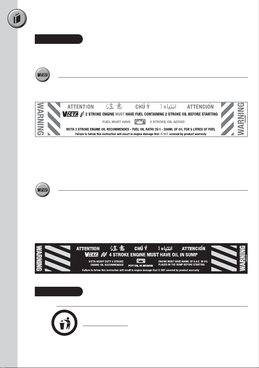
The following warning labels are attached to your mower on purchase.
Please read before discarding.
2 Stroke Label
Victa 2 Stroke Engine
Fuel Oil Ratio 25:1 = 200ml of Oil for 5 Litres of Fuel
Victa Formula V 2 Stroke High Performance Motor Oil (fuel oil ratio 50:1)
100ml of Oil to 5 Litres of Unleaded Fuel.
PLEASE NOTE 50:1 OIL RATIO IS ONLY WITH
APPROVED “VICTA FORMULA V 2 STROKE OIL”
4 Stroke Label
Briggs & Stratton Engine
Engine must have 600ml off S.A.E. 30 Oil placed in the Sump Before Starting
Honda Engine
Engine must have 550ml of S.A.E. 30 Oil placed in the Sump Before Starting
Dust Cap
Removal of Blue Dust Cap
(Victa 4 Stroke Briggs & Stratton Mowers Only)
Dispose of dust cap from under fuel cap before initial filling
DO NOT REPLACE
Page 3
Table of Contents
Important Notes 1
Safety & Handling 2
Assembly Procedures 5
Operating Instructions 10
Maintenance & Care 11
Questions & Answers 16
Unit Details
Safety Instructions
Hazards
Personal Safety Equipment
Grasscatcher
Handle Knobs/Toggles
Mulching Plug
Aerogrip Handle Assembly
Assembly Procedure
Attaching The Remote Air Filter Housing
Height Adjustment
Mulching Tips
Cleaning
Blade Replacement
Remote Air Filter Maintenance
Replacing Air Filters
Remote Air Filter Maintenance
- Aerogrip Handles
Maintenance Chart
Troubleshooting
Warranty 17
National Service Directory 19
Page 4

IMPORTANTNOTES
Congratulations on your purchase of a top quality Victa lawnmower. This instruction manual will
aid in the assembly, operation and maintenance of your new lawnmower.
Please read carefully ensure safety and the long life of your product.
Do not operate the unit before reading this manual.
Do not operate before reading the ‘Engine Manual’.
Keep this instruction manual in a safe place for future reference or if service is required on your unit.
Please read the ‘Warranty’ section carefully
Unit Details
When unpacking the unit, ensure that all component parts listed below have been provided.
Should there be a problem, notify the place of purchase.
You should find the following enclosed:
•1 VICTA lawnmower
•1 Unassembled grass catcher & assembly kit (Catcher models)
•1 Engine manual
•1 Mulching plug (Mulch or Catch models only)
1
Page 5
Safety Instructions
Transporting the mower
•Turn the engine off, by moving the throttle lever to the 'STOP' position and switching the
fuel tap off (where fitted).
• Disconnect the spark plug lead and wedge it between the cylinder head fins.
•Do not transport the mower in a vehicle if there is fuel in the fuel tank.
• Remove the starter key and disconnect the battery (Keystart models only).
Before using the mower
• Do not start the mower until you have studied the instruction manuals.
• Know the mower controls. Learn how to stop the engine quickly in an emergency by
moving the throttle to the 'STOP' position.
• Before using the mower, ensure that the blade assembly is not worn or damaged.
Always replace worn or damaged blades and bolts in sets to preserve correct balance.
Damaged or worn blades and bolts are major hazards. Use genuine VICTA spare parts
only.
• Please note blades are tucked under blade disc for safety and transport reasons
before use. Once the engine is started they will relocate themselves for cutting.
• Check all fasteners regularly. Always ensure the mower is in a safe operating condition.
• Check for grass build up around the engine and muffler which may cause overheating
and/or a fire hazard.
• Do not start the engine unless the rear flap and/or grasscatcher are securely in position.
Operating the mower
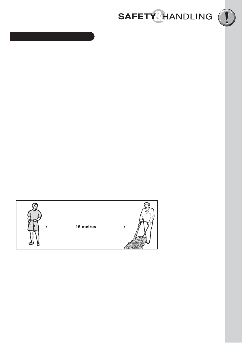
• Do not mow while people or pets are in the vicinity of the mower or within the mowing
area. Ensure that bystanders are a minimum of 15 metres away.
• Do not mow in bare feet or open shoes. Wear long trousers and heavy footwear.
•Make sure the lawn is clear of sticks, stones, bones, wire and debris before mowing.
These could be thrown by the blades and cause injury or damage.
•Start the engine carefully with feet well clear of blades. Do not tilt the mower when
starting the engine.
• Stop the engine whenever you leave the mower, even for a moment.
• Mow only in good daylight.
• Keep hands and feet away from r
• Do not over speed the engine or alter the governor settings. Excessive engine speed is
dangerous and shortens mower life.
otating parts beneath mower when engine is running.
2
Page 6

Safety Instructions (cont.)
• Never lift, carry or tilt the mower when the engine is running.
• Stop the engine before pushing the mower across gravel, paths or roads. Stop the
engine before the mower leaves the lawn.
• Stop the engine before adjusting the cutting height.
• Mow across the face of a slope, never up or down. Use extreme caution when changing
direction on a slope. Do not mow on excessively steep slopes.
• Never mow by pulling the mower towards you. You may slip and pull the mower on top
of your feet.
•Walk with the mower, never run.
•The safety distance determined by the guiding handles must be maintained at all times.
• At the conclusion of mowing, always turn the mower off using the throttle lever then turn
fuel tap off (where fitted).
Maintaining the mower
• If the mower begins to vibrate abnormally, or if it strikes a foreign object - STOP the
engine, disconnect the spark plug lead from the spark plug and carefully wedge it
between the cylinder fins. Inspect the mower and blades for any damage.
• Replace worn or faulty mufflers as they adversely affect engine performance and increase
emissions.
• VICTA recommends that all maintenance, repair and inspection work be carried out by a
VICTA Authorised Service Centre.
• Store the mower in a well ventilated area, away from any naked flames such as those
found in hot water heaters.
Refuelling the mower
• Refuel the mower outdoors only.
• Do not smoke when refuelling the engine. Never add fuel or remove the fuel cap while
the engine is running or hot. If fuel is spilt, do not start the engine. Move the mower
away from the area of the spill. Do not create any source of ignition until fuel vapours
have dissipated.
• Store fuel in a cool place and in a container specifically designed for the purpose. VICTA
supplies a 5 litre fuel can as an optional extra. Plastic containers are unsuitable, except
those specifically designed to hold fuel.
3
Page 7

Hazards
The following safety precautions must be strictly observed to avoid the risk of damage or
personal injury.
• Do not smoke while operating or refuelling the mower. Never add fuel or remove the fuel cap
while the engine is running or hot. If the fuel is spilt, do not start the engine. Move the mower
away from the area of the spill. Do not create any source of ignition until the fuel vapours have
dissipated.
• Check all fasteners regularly. Always ensure that the mower is in safe operating condition.
Use genuine spare parts only.
• Do not operate the mower in confined spaces where exhaust fumes (carbon monoxide) can
collect.
• Stop the engine whenever you leave the mower, even if only for a moment.
• Stop the engine when emptying the grasscatcher. Never try to clear grass from inside the
mower while the engine is running.
•Never lift, carry or tilt the mower when the engine is running.
• Bystanders must be at least 15 metres away during operation of the mower, as rocks and
other materials may be thrown at high velocities. Switch the unit off immediately if approached.
• Never use the mower unless the grasscatcher and/or the rear flap are correctly assembled and
fitted.
Personal Safety Equipment
Recommended safety equipment to wear when working with your lawnmower:
A set of ear muffs.
A pair of protective gloves.
A pair of safety boots.
Eye Protection.
4
Page 8
ASSEMBLYPROCEDURES
Grasscatcher
Assembling the Grasscatcher
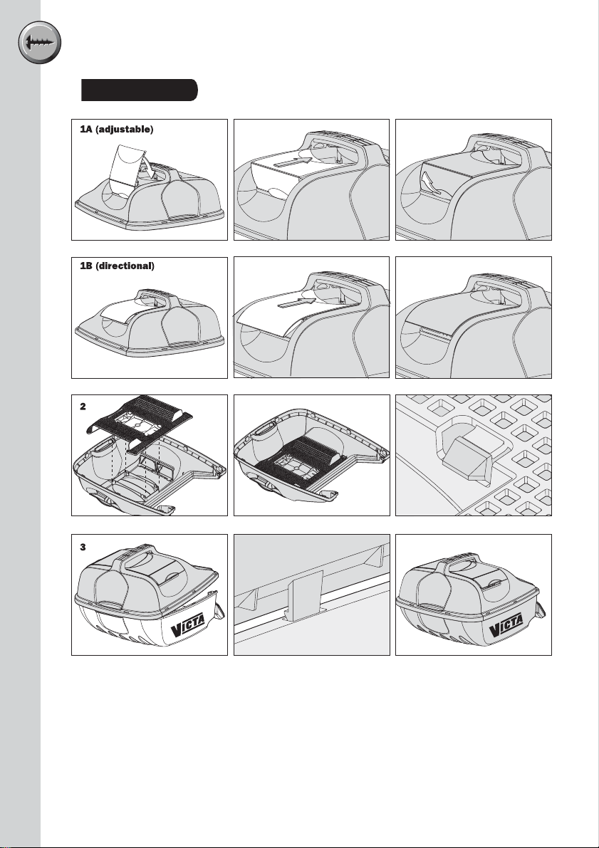
1 Assemble the adjustable covers 1A or directional covers 1B to the top half of the
grasscatcher (If applicable to your model). Check that all of the snap hooks have engaged
securely.
2 Locate the centre protrusion of the mesh into the centre hole on the inside of the catcher top,
ensuring the curved edge of the mesh faces the rear handle. Firmly push the mesh into the
top half of the catcher, making sure that the four snap hooks engage securely.
3 Loosely locate the rear handle areas of the top and bottom catcher halves then loosely locate
the side edges. Check that all eight hooks from the top half are loosely located in the slots
on the bottom half then firmly push the two halves together over each snap hook. Check that
5
all of the snap hooks have engaged securely.
4 Tighten the two screws fitted to the front of the catcher.
Page 9
ASSEMBLYPROCEDURES
Grasscatcher
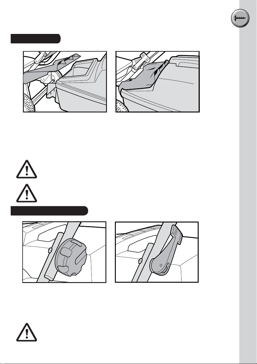
Fitting the Grasscatcher
•Stop the engine.
•Raise the rear flap. Locate the grasscatcher tongue over the rear axle and insert the
grasscatcher under the rear flap.
• Lower the rear flap to retain the grasscatcher .
STOP the engine before fitting or removing the grasscatcher.
Never use the mower unless the grasscatcher and/or the rear
flap are correctly assembled and fitted.
Handle Knobs/Toggles
Mowers will have either knobs or toggles to fix the handles in position. Refer to the
instruction below which is specific to your particular model.
•Tighten the handle knobs to secure the upper handle to the lower handle.
• Flip the handle toggles to secure the upper handle to the lower handle.
When folding or unfolding the handles, ensure that the starter switch
lead is not caught or stretched (Keystart models only).
6
Page 10

ASSEMBLYPROCEDURES
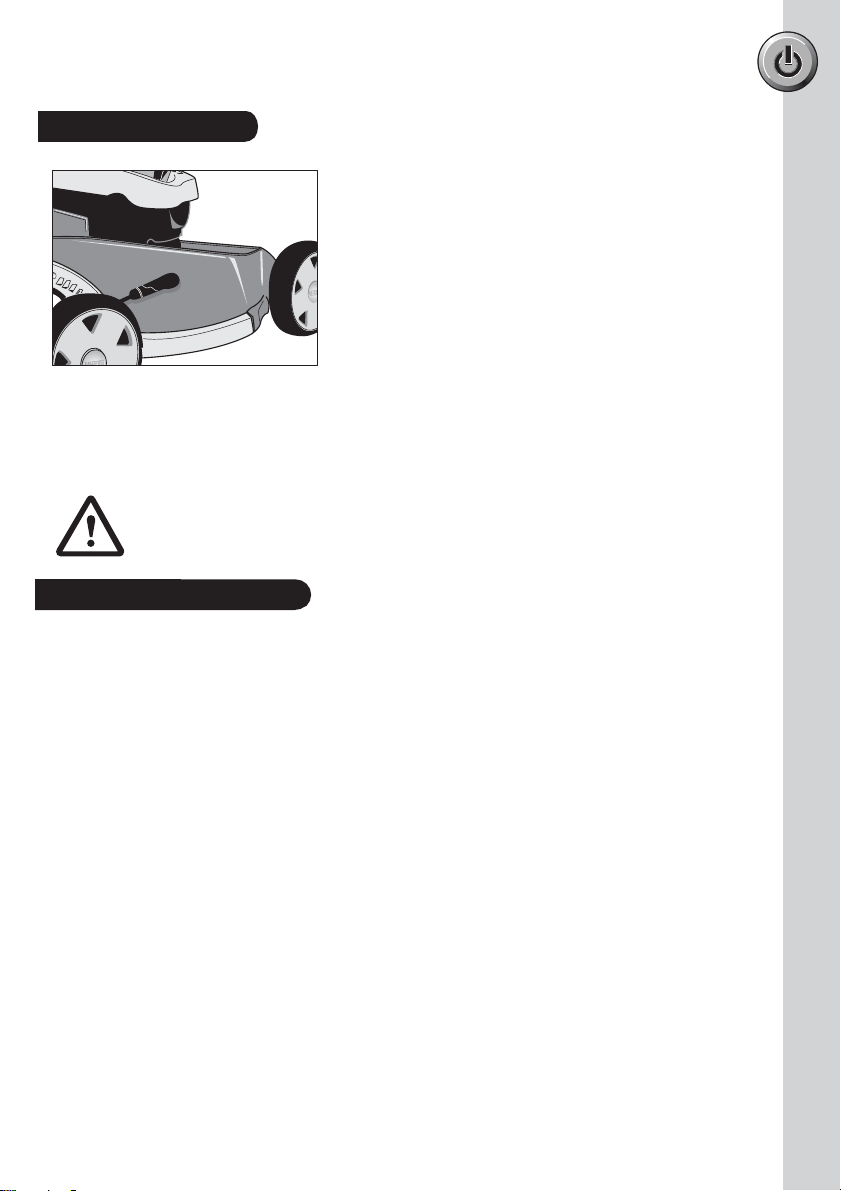
Mulching Plug (Mulch or Catch models only)
• Stop the engine and set the mower height setting.
• Mulching is most effective between height settings 4 and 10.
• Lift the rear flap and identify the support plate as shown. Note the orientation of the
mulching plug.
• Insert the mulching plug into the baseplate.
• Ensure that the mulching plug is resting on the support plate and is positioned against
the inside of the baseplate. Push the mulching plug down so that it rests flush against
the rear cross member.
•Close the rear flap ensuring that it closes fully. The rear flap should rest on the mulching
plug as shown in the sectional illustration.
STOP the engine before inserting or removing the mulching insert.
7
Page 11

ASSEMBLYPROCEDURES
Aerogrip Handle Assembly
11
2
55
66
33
44
Your Aerogrip handle may require some
assembly before its first use. If the upper
and lower handle have been supplied
unattached, follow these instructions below.
PIVOT JOINT COMPONENTS
ITEMS QTY
1. Upper Handle x 1
2. Centre knuckle x 1
3. Inner mating pieces x 2
4. Outer mating pieces x 2
5. Fastening knobs x 2
(incl. bolt)
6. Lower handles x 2
Assembly Procedure
1. Unscrew fastening knobs and outer mating pieces from each side of pivot joint assembly.
2. Lay the upper handle across the engine cowl of the lawnmower, with the bend facing
down (see fig 1).
3. Position the ends of the upper handle over the lower handles at the pivot joint, so that the
holes are all aligned.
4. Replace the outer mating pieces on each side and partly tighten into place with fastening
knobs, but do not fully tighten yet (see fig 2).
5. The Aerogrip handle may now be lifted into its normal operating position, and the fastening
knobs fully tightened.
Fig 1. Fig 2.
8
Page 12

ASSEMBLYPROCEDURES
Attaching The Remote Air Filter Housing – Aerogrip Handles
2 Stroke Models
Air filter
housing
Aerogrip
handle
Screw
(Please Note:
Do not over
tighten)
Fig 3. Fig 4.
4 Stroke Models
Screw
2 Stroke Models
Slide the air filter housing onto the upper handle. Position locating lug
into hole in handle and secure with screw (see Fig.3). Be careful not
to over tighten, as the plastic thread may be damaged.
Nut
Throttle
Control
25mm
Aerogrip
handle
Screw
Nut
Air filter
housing
(Actual size)
4 Stroke Models
1. Firstly secure the throttle control to the right
hand side of handle, on the outside
(see Fig. 4) using the 50mm screw and
nut pictured here.
2. For models supplied with r
emote air filter. After
attaching the throttle control, secure the air filter
housing to the right hand side of handle, on the
inside (also fig 4), using the 38mm screw
& nut pictured here.
50mm (Actual size)
38mm (Actual size)
9
Page 13
OPERATINGINSTRUCTIONS
Height Adjustment
1
2
3
4
Height adjustment allows lawn to be cut at different lengths.
• Set cutting height by adjusting the height lever.
• For Mulch or Catch models, mulch grass between settings 4 to 10.
•A lower setting may be used depending upon conditions.
STOP the engine before adjusting the cutting height.
Mowing & Mulching Tips
•A mulching mower is designed to cut, retain, and recut the clippings until they have reached
a very small size. These are then blown down into the root system as nutrients for your lawn.
• For best mulching results only mow the top 1” / 2.5cm of lawn growth. If grass has become
excessively long choose a height setting and gradually reduce the cutting height after each
pass, or use catcher.
• Mulch grass between heights settings 4 and 10. A lower setting may be used depending on
conditions.
• Dry grass will aid in the mulching action of the mower.
• Cut the grass regularly to avoid it becoming too long and making it difficult to mulch.
• As a general rule, only cut the top one third of the grass length (approximately). More than
this may leave an untidy appearance and finish.
• Mulching is sensitive to the chosen height setting. If the height setting is too low cut grass
may be left on top of the lawn. In this case raise the height setting.
• Cut the grass in the late afternoon or morning. This will stop the grass being damaged by
direct sunlight.
•To maintain cutting performance keep the underside of the mower clean.
• The cutting pattern should be varied from week to week (eg. North-South to East-West).
• When using a mulcher the grass tends to be carried along with the mower. Mow from the
thick grass to light grass as this will deposit clippings and encourage growth in these areas.
• Excessively long grass will not be mulched adequately, in this case, it is recommended to
use catcher.
•Worn or incorrect blades will reduce lawn finish and will not mulch properly. Use only genuine
Victa blades and replace them regularly.
10
Page 14

Cleaning
Before cleaning the mower, ensure the throttle lever is in the 'STOP'
position. Turn the fuel tap off, disconnect the spark plug lead and
wedge it between the cylinder fins, and disconnect the battery on
Keystart models.
• Remove grass build up from the air intakes on the top of the mower cowl, around the
engine and carburettor, and around the air filter body.
• The underside of the mower should be cleaned regularly to remove dirt and grass build
up, as any build up will adversely affect grass catching and mulching performance and
can promote corrosion on steel baseplates.
4 Stroke Mower
Primer button
Spark
Plug
4 Stroke
Mower
Primer button
Spark
Plug
• When cleaning the underside of the mower, always tilt handle back to ground level so
the front wheels are off the ground and spark plug is pointing to the sky. Tilting in other
directions can cause the oil to contaminate the fuel & damage airfilter causing starting
difficulties.
•A hose may be used on the underside of your
mower ONLY. Care must be taken to NOT get
water into the engine, as it may damage the
magneto or get into the fuel system.
• If your mower is fitted with a washport, simply
Washport
attach a garden hose whilst the engine is running
and turn on the water.
• On Keystart models keep the battery,
starter switch, starter motor and all leads dry.
•To prevent chassis corrosion,
the underside of your mower should be cleaned
immediately after mowing an area which has
been recently dressed with sulphate
of ammonia or fertiliser.
• After cleaning, run the engine briefly to dry
off excess moisture before storing.
11
Page 15

Blade Replacement (All Models)
Model Blade & Bolt Set
All 19” Steel & Alloy Chassis Models CA094705
For Your Safety
• Never use the mower unless the grasscatcher or the guards supplied by the
manufacturer are in position.
• Before starting the mower check blades and bolts for damage or wear.
• If you strike an obstruction, stop the engine and check the blades for damage.
Worn and damaged blades are major hazards.
• Stop the engine and disconnect the spark plug lead before fitting new blades.
•Work from the catcher flap.
With the rear flap secured,
undo the blade nut, applying
upward pressure to the bolt
head into the blade disc. (the
head of the bolt will not rotate
due to the diamond shape in
the underside of the head).
Assembly: Fit as per the
drawing remembering to push
the head of the bolt into the
blade disc. (this will stop the
bolt head from turning).
Ensure correct order of
assembly.
DO NOT
•We recommend changing blades, bolts, nuts and washers as a set. Metal fatigue and
damage may occur which may not be visible to the operator. Always replace all blades to
ensure correct engine balance, reducing vibration and wear. Tighten nuts on blade bolts
to 14-19 Nm (Newton Metres) or 10-14ft lbs.
• Always turn the nut to check tightness, not the bolt.
lay mower on side (4 stroke models).
Text
Use only genuine replacement parts made and guaranteed by Victa.
Insist on them from your parts and service dealer.
Detailed fitting instructions are printed on genuine Victa blade packs.
Use of non-genuine blades may void your warranty, and could result in
damage or injury.
12
Page 16

Remote Air Filter Maintenance
For correct engine performance and to guard against dust entering the engine, causing
rapid wear, the air filter assembly must be clean and maintained in good condition. VICTA
recommends that the air filter element and seal ring are replaced annually, or more often in
dusty conditions. Always replace with genuine Victa spare parts. Use of non-genuine spare
parts may damage your mower engine, and void the product warranty.
Replacing Air Filters
STOP ENGINE.
(Fig. 1) 4 stroke models, twist filter cap anti-
clockwise and remove cap from filter
housing.
(Fig. 2) 2 stroke models, lever cap off using
screw driver in slot in side of filter body.
To stop loose material falling into filter body,
tilt upper handle so that filter body is up-side
down. Remove filter element and seal ring.
(Fig. 3) Clean filter element “A” by tapping it
on palm of hand. Do not use compressed air
or wash with any liquid. Examine element for
holes, splits or permanent clogging. Replace
if necessary.
Dust-off seal ring “B” and examine. Replace
if damaged or permanently crushed.
(Fig. 4) Fit or refit seal ring and filter element.
Tilt upper handle back to normal position.
Push filter cap on, ensuring teeth engage in
slots on filter housing.
Victa Air filter for all 2 stroke & 4 stroke
domestic models Part No AF072825
Fig. 2Fig. 1
Fig. 3
B
A
Fig. 4
13
Page 17

Remote Air Filter Maintenance – Aerogrip handles
1. Examine the air filter hosing for holes, chafing and leaks. Replace it if damaged.
Latch
Unclip here to
remove top
2. Remove the top cover of the air filter housing by squeezing the latch on the underside of the
housing and lifting upwards.
Element
3. Remove the element and the foam seal ring, taking care that any loose dirt does not fall into
the filter body.
4. Dust off the seal and examine it. Replace it if damaged or permanently crushed. Refit seal to
housing.
Lugs
Seal ring
5. Clean the element by slapping it on the palm of your hand. Do not use compressed air or
wash the element in any liquid. Examine the element for holes, splits or permanent clogging.
Replace the element if necessary. Refit element to housing.
6. Refit the top cover by making sure the lugs at the rear of the cover are located before clipping
in the latch.
14
Page 18

Maintenance Chart
Refer to the following table for routine
maintenance.
Time Period
Features Requirements
Lawnmower Visual inspection (leaks)
Throttle lever Check operation
Remote Air filter hose Check
Cutting System Inspect and check assembly
(Blades)
Rear flap Inspect and check assembly
Chassis Check for buildup of grass
Air filter Check
Engine Cylinder fins Clean
Spark plug Replace
All accessible fasteners Check
Engine mounting bolts Check & retighten
Mulching plug Inspect and check assembly
Muffler Inspect
Grasscatcher Check
Replace
Clean
Replace
Clean
Replace
Retighten
Replace
Clean
Replace
Before start
After finish
Refuelling
Weekly
Monthly
If faulty
If damaged
As required
••
•
••
•
••
••
•
•
•
•
•
••
••
••
•
•
•
••
••
••
•
•
•
15
Before carrying out maintenance, STOP the engine, disconnect the
spark plug lead from the spark plug and wedge it between the
cylinder head fins. Remove the starter key from the ignition switch of
Keystart models and disconnect the battery.
Never attempt maintenance that is not outlined in this manual. All
repair work must be carried out by a VICTA Authorised Service
Centre.
Page 19

Troubleshooting
In small engines generally, difficult starting and erratic running is most often caused by a
dirty spark plug. If a new spark plug of the correct type does not restore the engine to
proper operating condition, the problem may be solved by reference to the chart below.
Problem Possible cause Correction
Does not start Out of fuel Refill tank with correct fuel
Throttle lever in incorrect position Refer to 'Starting Procedures'
Spark plug lead not connected Press terminal cover fully onto
Engine flooded Turn fuel tap 'OFF'. Pull starter cord
Dirty spark plug Replace spark plug
Stale fuel in tank from last season Contact Service Centre
Water in fuel tank Contact Service Centre
Service required Contact Service Centre
Engine worn Contact Service Centre
Low or no oil (4 stroke) Check
Loss of Power Incorrect throttle setting Set throttle lever in the 'RUN' position
Dirty air filter element Clean or replace
Too low height adjustment Raise cutting height
Low or no oil (4 stroke) Check
Poor cutting or Blades worn or damaged Replace
catching
Excessive vibrations Build up of grass and dirt on upper Clean
Engine stops Fuel supply blocked Check fuel line
frequently
Blade disc loose Contact Service Centre
Slow running Refer to 'Loss of Power' above
Blades restricted by grass and dirt Remove spark plug lead and clean
accumulated under the baseplate under the baseplate
Blocked vents in grasscatcher Clean vents
surface of blade disc
Blades out of balance Replace both blades
Bent or damaged disc or blade Replace disc or both blades
Looseness of assembly Check all nuts for tightness
Low or no oil (4 stroke) Check
Engine worn or seized Contact Service Centre
Fuel cap not venting Check / Loosen cap slightly
Low or no oil (4 stroke) Check
the spark plug
until engine starts, then turn fuel
tap 'ON'
If running difficulties continue, contact your closest VICTA Authorised Service Centre as
listed in the back of this manual.
16
Page 20

WARRANTY
Warranty
Consumer Rights
The buyer should be aware that in relation to goods which are of a kind ordinarily acquired
for personal, domestic or household use or consumption, certain provisions such as the
Trade Practices Act, 1974 (Aust) and the Consumer Guarantees Act, 1993 (NZ) apply. The
terms set out below do not exclude rights and remedies implied by a statute which are
non-excludable and which may be more extensive than those provided by this warranty.
Warranty Service
Warranty Service under both the Express Warranty and the warranties implied by law is
available at any VICTA Authorised Service Centre. These centres are staffed and equipped
to provide expert service.
VICTA Express Warranty
The VICTA Express Warranty is additional to the conditions and warranties which are
mandatorily implied by the laws and regulations of the individual States and Territories of
Australia and the Trade Practices Act, 1974 (Aust) and the Consumer Guarantees Act in
New Zealand and any non-excludable laws.
Warranty Period
Domestic Models Domestic Use Commercial Use
Corvette 300, Pace, Clubsman 1 Year 3 Months
Tiger, Hurricane, Hawk,
Vortex, Silver Streak,
Charger, Tornado Classic,
Lawnkeeper
VSX - Engine only 3 Years 3 Months
Key Start - Battery only 6 Months 3 Months
Mulch or Catch 2 Years 3 Months
Victa Razor, Tornado, 2 Years 3 Months
To rnado Edge, Mustang,
Keystart, Statesman,Bronco,
Corvette 400, Corvette 500,
Lawnmaster, Mayfair, Panther,
Wildcat, Tiger
17
Under Express Warranty the 'Lawnmower' is warranted from the date of purchase against
mechanical defects and faulty workmanship or material. Express Warranty covers only the
replacement, repair or adjustment of parts which fail due to a fault in manufacture.
Defective parts will be replaced or serviced by an Authorised VICTA representative without
charge for labour or materials, subject to conditions. Repairs or adjustments required by
normal use or by failure to follow the manufacturer's instructions are chargeable to the
owner.
VICTA Service Representatives or agents are authorised to determine whether a claim will
be covered under warranty, or payable by the owner on completion.
Page 21

WARRANTY
Warranty (cont.)
Conditions (cont.)
You should seek independent legal advice to determine whether a claim not covered by the
Express Warranty is covered by any warranties implied by law.
• Express Warranty applies to the original purchaser only. Proof of purchase date must be
provided prior to Express Warranty work.
• Use of parts other than genuine VICTA Spare Parts cancels the Express Warranty.
• Repairs other than by a VICTA Authorised Service Centre cancels the Express Warranty.
• Altering the product (including governed speed) cancels the Express Warranty..
•A 'lawnmower' run with incorrect fuel, oil or oil level, is not covered by
the Express Warranty.
• Failure to properly service cooling or air filtration systems cancels the Express Warranty.
• Failure to follow the instruction manual or labels attached cancels the Express Warranty.
•Fair and reasonable wear is not covered by the Express Warranty.
• Damage from an accident, misuse or neglect is not covered by the Express Warranty.
• Costs of transportation of the 'lawnmower' are to be paid by the owner.
• Blades and spark plugs are not covered by the Express Warranty.
Limitations of Warranty
Nothing in these terms shall exclude, restrict or modify any term, condition, warranty or
liability implied into this contract by statute, where to do so would be unlawful or would
render any provision of this contract void. Subject to that, all warranties implied by statute
in respect of the goods are hereby expressly negated and VICTA's liability for the goods is
limited to any warranties issued in writing by VICTA and VICTA is excluded from any liability
whether under this contract or otherwise to the buyer of any third party for any loss, injury,
cost or damage (direct, indirect, special, consequential, or otherwise and whether or not
arising from a negligent act or omission of VICTA), incurred or suffered by reason for the
goods, their use, their design or any failure to deliver or delay in delivering them. Where it is
legal to do so, any remaining liability implied by statute or resulting from breach of any term,
condition or warranty implied by statute is limited to, at VICTA's sole option:
• the replacement of the goods or the supply of equivalent goods;
• the repair of goods;
•the payment of the cost of replacing the goods or of acquiring equivalent goods; or
• the payment of having the cost of the goods repaired.
In particular, your rights and remedies under the Trade Practices Act (Aust) and the
Consumer Guarantees Act (NZ) are not excluded.
18
Page 22

NATIONAL SERVICE DIRECTORY
NEW SOUTH WALES
NSW - SYDNEY METROPOLITAN
BEVERLY HILLS 2209 BEVERLY HILLS MOWERS 108 STONEY CREEK ROAD .................02 9570 5771
BLACKTOWN 2148 INDEPENDENT
CAMDEN 2570 MACARTHUR MOWERS 2 IRONBARK AVENUE .........................02 4655 7793
CAMPSIE 2194 HARRISON'S MOWERS 78-80 BEAMISH STREET .....................02 9789 6061
CASTLE HILL 2154 ALL SEASONS MOWER
DEE WHY 2099 ALLMOWERS 5 SOUTH CREEK ROAD.........................02 9982 8574
DRUMMOYNE 2047 KENNYS MOWERS 96 VICTORIA ROAD.............................02 9181 3509
EARLWOOD 2206 EARLWOOD LAWN MOWERS 174-176 WILLIAM STREET..................02 9718 2337
EMU PLAINS 2750 EMU PLAINS MOWERS 5/116 OLD BATHURST ROAD..............02 4735 5555
ENGADINE 2233 SOUTHERN MOWER CENTRE 2/116 CALDARRA AVENUE..................02 9520 9246
FORESTVILLE 2087 FOREST MOWERS 7 COOK STREET .................................02 9451 8800
GLENFIELD 2167 FIELDS MOWER CENTRE SHOP 6 HOSKING CRESCENT..............02 9605 3176
HORNSBY 2077 DUFFYS OUTDOOR
HORSLEY PARK 2164 HORSLEY PARK
HURSTVILLE 2220 LAWRENCE BROS
INGLEBURN 2565 INGLEBURN VILLAGE
LANE COVE 2066 LANE COVE MOWERS 692A MOWBRAY ROAD ......................02 9428 5472
LEPPINGTON 2171 LAWRENCE BROS,
LINDFIELD WEST 2070 LINDFIELD MOWER CENTRE 38 MOORE AVENUE............................02 9416 3271
LIVERPOOL 2170 LIVERPOOL POWER CENTRE 403 HUME HIGHWAY...........................02 9602 1862
MANLY NORTH 2095 MOWPOWER MANLY 396 PITTWATER ROAD........................02 9939 6729
MAROUBRA 2035 ANDREWS MOWERS 388 MALABAR ROAD ..........................02 9349 6396
MERRYLANDS WEST 2160 J & A MOWERS 39 IRRIGATION ROAD ..........................02 9636 4620
MONA VALE 2103 PRIDE MOWERS 3/92A MONA VALE ROAD...................02 9997 4888
MOOREBANK 2170 THE CHAINSAW CENTRE 4/66 HEATHCOTE ROAD .....................02 9602 2634
NORTH RICHMOND 2754 DICK PETRIKAS 385 TENNYSON ROAD
PENRITH 2750 PENRITH MOWER CENTER 87-91 YORK ROAD .............................02 4721 7744
PLUMPTON 2761 PROMPT MOWER SERVICE 295 ROOTY HILL ROAD NORTH...........02 9625 8787
ROOTY HILL 2766 ROOTY HILL MOWER &
ROUSE HILL 2155 KELLYVILLE LAWNCARE CNR MILE END &
RYDALMERE 2116 HOPPINGS SERVICE
SYLVANIA 2224 SYLVANIA MOWERS PTY LTD 57 PORT HACKING ROAD....................02 9522 5244
TAREN POINT 2229 RAMSGATE MOWER SERVICE 33 ALEXANDER AVENUE.....................02 9525 8536
TOONGABBIE 2146 EDROYS MOWERS
WEST RYDE 2114 RYDE CITY MOWERS 7-9 RYEDALE ROAD............................02 9809 0329
WETHERILL PARK 2164 MIGHTY MOWERS 1/21-23 DANIEL STREET ....................02 9604 3539
WINDSOR 2756 FITZGERALD
MOWER CENTRE UNIT 6, 12 ROMFORD ROAD...............02 9622 5188
STORE 23/8 VICTORIA AVENUE........................02 98991365
POWER EQUIPMENT 55 HUNTER STREET............................02 9477 1555
MOWER CENTRE 1846 THE HORSLEY DRIVE..................02 9620 1569
POWER EQUIPMENT 19 FOREST ROAD...............................02 9587 2744
MOWERS 2A MEMORIAL AVENUE.......................02 9605 1100
LEPPINGTON 1640 CAMDEN VALLEY WAY ...............02 9606 4255
CHAINSAWS (TENNYSON)........................................02 4576 5555
CHAINSAW CTR SHOP 3 & 5, ORCAM LANE.................02 9625 8916
CENTRE WINDSOR ROADS ...............................02 9629 2811
CENTRE P/LTD 251 VICTORIA ROAD...........................02 9638 5777
& CHAINSAWS 45 STATION ROAD ..............................02 9624 6500
MOTORS PTY LTD 9 FITZGERALD STREET .......................02 4577 3401
YAGOONA 2199 ASHBURY MOWERS 16 ROOKWOOD ROAD ........................02 9709 3654
YENNORA 2165 YENNORA MOWER CENTRE 154 FAIRFIELD STREET.......................02 9681 7233
NSW - COUNTRY
ARMIDALE 2350 L W BURGESS PTY LTD 82 RUSDEN STREET............................02 6772 2227
BATEMANS BAY 2536 NEW BAY MOWERS 4/67 HUGHES STREET ........................02 4472 5314
BATHURST 2795 MOWERS & MORE
BEGA 2550 BEGA MOWER CENTRE CNR PEDEN & UPPER STS .................02 6492 1179
BELCONNEN ACT 2617 CANBERRA MOWER SERVICE 10 WEEDON CLOSE............................02 6251 2827
BELMONT 2280 JOHN SILVEY MOWERS CNR MARKS & HENRY STREETS .........02 4947 7150
BOURKE 2840 TREV RANDALL OXLEY STREET....................................02 6872 1443
BOWRAL 2576 BOWRAL MOWER SERVICE 250 BONG BONG STREET...................02 4861 3487
BULLI 2516 HY-QUAL MOWER SERVICE 159 PRINCES HIGHWAY......................02 4267 3010
CESSNOCK 2325 CESSNOCK MOWERS
CHARMHAVEN 2263 CENTRAL COAST MOWERS
COOTAMUNDRA 2590 HALL'S CYCLE &
COFFS HARBOUR 2450 CUNNINGHAMS HOME
CULBURRA BEACH 2540 LAKE CIRCUIT MOWERS 9 WESTERN STREET ...........................02 4447 3233
DAPTO 2530 HIGHWAY CENTRE MOWERS 32 PRINCES HIGHWAY ........................02 4261 7999
DUBBO 2830 DUBBO MOWERS
FORBES 2871 FRANK SPICE MOWERS 20-22 DOWLING STREET ....................02 6851 1755
FORSTER 2428 BARRY AUSTIN
GLEN INNES 2370 SMALL ENGINE SERVICES LOT 2 LAMBETH STREET ....................02 6732 1441
GOSFORD EAST 2250 BRIDGE MOWER
GOSFORD NORTH 2250 PRIDE MOWERS 370 MANN STREET.............................02 4325 1803
GOULBURN 2580 GOULBURN MOWER
GRAFTON 2460 CLARENCE VALLEY
GRIFFITH 2680 GRAS MOWER CENTRE 69 KIDMAN WAY .................................02 6962 2348
GUNNEDAH 2380 GORDON TURNER
INVERELL 2360 MOTOR MECCA 233 BYRON STREET ...........................02 6722 2844
KEMPSEY SOUTH 2440 MACLEAY VALLEY 39 LACHLAN STREET
LEETON 2705 EURELL'S 36-38 PINE AVENUE............................02 6953 2999
LITHGOW 2790 R & A CHAINSAW
MAITLAND (EAST) 2323 MAITLAND MOWER CENTRE 61 TURTON STREET ............................02 4934 8933
MERIMBULA 2548 MERIMBULA MOWERS
MITCHELL ACT 2911 MITCHELL LAWNMOWER
MORISSET 2264 PARSONS OUTDOOR POWER GATEWAY BLVD & ADVANTAGE AVE.....02 4973 3606
MOREE 2400 LOWREY SMALL MOTORS 307 GOSPORT STREET .......................02 6752 2744
BATHURST 85 KEPPEL STREET.............................02 6331 6022
& CHAINSAWS P/L 24 ABERDARE ROAD...........................02 4990 4273
& CHAINSAWS 205 PACIFIC HIGHWAY........................02 4392 6766
POWER PRODUCTS 62 THOMPSON STREET......................02 6942 1682
HARDWARE 177 HARBOUR DRIVE..........................02 6652 1499
& CHAINSAWS 28 COBBORA ROAD............................02 6882 3122
MOWER REPAIRS 36 LAKE STREET.................................02 6554 6935
& CHAINSAW CENTRE 59 GEORGE STREET ...........................02 4325 2107
& CHAINSAW CENTRE 26 UNION STREET...............................02 4821 3831
SMALL ENGINES 131 PRINCE STREET...........................02 6642 2386
MOTORCYCLES 336 CONADILLY STREET .....................02 6742 1937
MOWER CENTRE (PACIFIC HWY).....................................02 6562 8822
& MOWER SUPPLIES 327 MAIN STREET ..............................02 6352 3014
& MARINE 43 MERIMBULA DRIVE........................02 6495 4495
CENTRE 32 SANFORD STREET .........................02 6241 4806
Page 23

NATIONAL SERVICE DIRECTORY
MORUYA 2537 MORUYA MOWER &
MUDGEE 2850 BILL'S MUDGEE
NARRANDERA 2700 EURELLS 16 BOLTON STREET............................02 6959 2949
NEWCASTLE 2296 NEWCASTLE CHAINSAWS 158 MAITLAND ROAD,
NOWRA 2540 DAYS MOWER SERVICE 17 NOWRA LANE ................................02 4421 4468
NOWRA 2541 WRIGHTS CHAINSAWS 65 KINGHORN STREET ........................02 4421 4640
OAK FLATS 2527 EDWARDS MOWER REPAIRS 53 CENTRAL AVENUE..........................02 4256 1221
ORANGE 2800 BROWNS MOWERS
PARKES 2870 FRANK SPICE
PHILLIP ACT 2606 CANBERRA MOWER SERVICE 26 DUNDAS COURT ............................02 6281 2858
PORT MACQUARIE 2444 PETERS MOWER CENTRE 26 MILTON CIRCUIT ............................02 6581 0301
QUEANBEYAN 2620 H & S MOWER SALES
SALAMANDER BAY 2317 SALAMANDER
SCONE 2337 SCONE OUTDOOR PRODUCTS 230 KELLY STREET.............................02 6545 3033
SINGLETON 2330 SINGLETON MOWERS
TAMWORTH 2340 TAMWORTH CHAINSAW
TAREE 2430 MANNING MOWERS
TAREE 2430 MID COAST MOWERS 35 CRESCENT AVENUE .......................02 6552 4103
TEMORA 2666 REX PERROT MOWERS 81 HOSKINS STREET...........................02 6977 2677
TOORMINA 2452 PJ'S MOWER SERVICE 2 HULBERTS ROAD.............................02 6658 1918
TUMBI UMBI 2261 TUMBI MOWERS PTY LTD 39 WYONG ROAD...............................02 4388 1274
TUMUT 2720 PIDSLEY BROS 48-50 CAPPER STREET .....................02 6947 2155
ULLADULLA 2539 KEN MATTHEWS AUTO
UNANDERRA 2526 BOB HALL’S WOLLONGONG
UNANDERRA 2526 UNANDERRA
WAGGA SOUTH 2650 HARVEY'S MOWER
WAUCHOPE 2446 C.B.S. 202 HIGH STREET...............................02 6585 2077
WEE WAA 2388 AGIES RURAL RETAIL LOT 422 BOOLCARROL ROAD ............02 6795 4202
WELLINGTON 2820 DON JACKSON CHAINSAW
WOLLONGONG 2500 ILLAWARRA GARDEN
NORTH EQUIPMENT 1 FLINDERS STREET ...........................02 4226 1311
WOY WOY 2256 BLACKWALL MOWER CENTRE 72 MEMORIAL AVENUE.......................02 4343 1624
WYONG 2259 PRIDE MOWERS PTY LTD 1 MCPHERSON AVENUE......................02 4352 1963
YASS 2582 YASS OUTDOOR
YOUNG 2594 TRESILIAN & DUN 44-78 LOVELL STREET.......................02 6382 1799
CHAINSAW CENTRE FORD STREET.....................................02 4474 3322
CHAINSAW CENTRE 10 INDUSTRIAL AVENUE......................02 6372 4122
& MOWERS (ISLINGTON) ........................................02 4961 1332
AND CHAINSAWS 33 PEISLEY STREET............................02 6362 4933
MOWERS (PARKES) 38-40 WOODWARD STREET...............02 6862 2244
& SERVICE 175-177 GILMORE ROAD ...................02 6297 5020
MOWER CENTRE 336 SOLDIERS POINT ROAD ...............02 4982 7070
& CHAINSAWS 32 GEORGE STREET ..........................02 6572 4244
& MOWER CENTRE 205 PEEL STREET...............................02 6766 4337
& CHAINSAWS SAVOY CTR, MANNING STREET...........02 6552 7277
& MOWER CENTRE 149 PRINCES HIGHWAY.....................02 4455 1645
MOWERS 8 ORANGE GROVE AVENUE .................02 4271 3476
MOWER CENTRE 51 PRINCES HIGHWAY........................02 4271 2121
& CHAINSAW CENTRE 48 PEARSON STREET .........................02 6925 2234
& MOWER CTR 59 GOBOLION STREET ........................02 6845 1267
POWER CENTRE 230 COMUR STREET ..........................02 6226 1648
VICTORIA
VICTORIA - MELBOURNE METROPOLITAN
ALTONA 3018 ALTONA MOWERPOWER 90 MILLERS ROAD..............................03 9314 6656
BAYSWATER 3153 BAYBURY MOWER CENTRE 345-347 BAYSWATER ROAD...............03 9729 1250
BRIGHTON 3187 BRIGHTON MOWERPOWER 361 NEPEAN HIGHWAY .......................03 9596 4238
COBURG 3058 AUSTRALIAN MOWER
CHELSEA 3196 CHELSEA MOWERPOWER 486 NEPEAN HIGHWAY.......................03 9772 3573
DIAMOND CREEK 3089 MOWERS AND MORE 272 DIAMOND CREEK ROAD ..............03 9434 3066
DONCASTER EAST 3109 JACKSON COURT MOWERS 16-18 JACKSON COURT ....................03 9848 6136
DOVETON 3177 POWERQUIP MOWER & CNR PRINCES HIGHWAY
EPPING 3076 EPPING MOWER MART 817 HIGH STREET...............................03 9401 3547
ESSENDON 3040 PRECISION MOWERS PTY LTD 977 MT ALEXANDER ROAD.................03 9379 2748
FERNTREE GULLY 3156 FERNTREE GULLY
FOREST HILLS 3131 FOREST HILLS
FRANKSTON 3199 FRANKSTON GARDEN
GLENROY 3046 SPEEDIE MOWER SERVICE 117 WHEATSHEAF ROAD....................03 9306 4002
GREENSBOROUGH 3088 GREENVALLEY
HALLAM 3803 POWERQUIP MOWER
HAMPTON 3188 HAMPTON MOWERPOWER 87 LUDSTONE STREET........................03 9598 6741
HEIDELBERG 3084 HEIDELBERG
HOPPERS 3030 HOPPERS CROSSING
CROSSING MOWER MART 159 OLD GEELONG ROAD...................03 9748 3811
KEW 3102 KEW MOWER SERVICE 775 HIGH STREET...............................03 9859 3464
KEYSBOROUGH 3173 FOORD'S MOWER MART 128 CHELTENHAM ROAD...................03 9792 3449
KINGSBURY 3083 PLENTY MOWER &
MT WAVERLEY 3149 MT WAVERLEY
NOTTING HILL 3168 PETE'S MOWER POWER 408 FERNTREE GULLY ROAD ..............03 9560 5526
OAKLEIGH SOUTH 3167 OAKLEIGH MOWERPOWER 1130-1132 NORTH ROAD...................03 9563 7299
RINGWOOD 3134 MORTONS
SUNSHINE 3020 SUNSHINE MOTOR
SUPPLY 1115 SYDNEY ROAD...........................03 9350 1668
CHAINSAW CTR & PROGRESS ST .................................03 9793 3177
MOWERPOWER 1845 FERNTREE GULLY ROAD ...........03 9756 0558
MOWERPOWER 421 SPRINGVALE ROAD......................03 9878 0211
MACHINERY 29A WELLS ROAD...............................03 9776 8755
MOWERS PTY LTD 125-127 MAIN STREET.......................03 9435 1002
& CHAINSAW CTR 261 PRINCES HIGHWAY......................03 9796 5045
MOWERS PTY LTD 66 BELL STREET.................................03 9458 1220
CHAINSAW SERVICE 899 PLENTY ROAD .............................03 9478 7011
MOWERPOWER 53 WADHAM PARADE.........................03 9807 1767
MACHINERY PTY LTD 517 MAROONDAH HIGHWAY...............03 9870 7133
MOWER SALES CNR DICKSON ST & STATION PL.........03 9311 3560
Page 24

NATIONAL SERVICE DIRECTORY
VICTORIA - COUNTRY
ALBURY (NSW) 2640 ALBURY ENG.
BAIRNSDALE 3875 B & J CRANE PTY LTD 92 MCLEOD STREET...........................03 5152 3008
BALLARAT 3350 HENDERSON MOTOR
BEECHWORTH 3747 BEECHWORTH MACHINERY 30-32 HIGH STREET ...........................03 5728 2531
BENALLA 3672 SQUIRES SPORTS
BENDIGO 3555 GOLDEN SQUARE
CASTLEMAINE 3450 REWELL'S MOWER SERVICE 315 BAKER STREET............................03 5472 1484
COBRAM 3644 MILLERS MOWERS
COLAC 3250 J & G HOLT 329-331 MURRAY STREET..................03 5231 4933
CRANBOURNE 3977 FOORD'S MOWER MART 2/270 SOUTH GIPPSLAND HWY..........03 5995 1133
DENILIQUIN (NSW) 2710 RON HARDWICK PTY LTD 336 CRESSY STREET..........................03 5881 1077
DIMBOOLA 3414 DIMBOOLA STOCKFOOD
DROUIN 3818 DROUIN MOWERS
FINLEY (NSW) 2713 BURTON WILSON AGENCIES 204-208 MURRAY STREET..................03 5883 1188
GEELONG NORTH 3215 MOWERS GALORE 20 THOMPSON ROAD .........................03 5272 1066
GROVEDALE 3216 MOWERS GALORE 198 TORQUAY ROAD...........................03 5244 0620
HAMILTON 3300 BARRY FRANCIS PTY LTD 52-54 LONSDALE STREET ..................03 5572 1899
HASTINGS 3915 HASTINGS MOWERS 2013 FRANKSTON & FLINDERS RD .....03 5979 1382
HORSHAM 3400 HORSHAM LAWN
KILMORE 3764 ALPHA MCDELTA LANCEFIELD & BUTLER ROADS...........03 5782 2543
KOONDROOK 3580 MOLIN MOTORCYCLE
KYABRAM 3620 RIGHTLINE MOTORCYCLE
KYNETON 3444 MACBEAN'S HARDWARE 68-74 MOLLISON STREET ..................03 5422 1033
LAVINGTON (NSW) 2641 MOWER CITY ALBURY UNIT 1 / 453 WAGGA ROAD................02 6040 2033
LEONGATHA 3953 MARRIOTTS M/CYCLE CNR ALLISON & STH
MANSFIELD 3722 MANSFIELD CHAINSAW
MARYBOROUGH 3465 COSTELOW & SONS 60 CLARENDON STREET .....................03 5461 1373
MILDURA 3500 BRAIDIES MILDURA MOWER
MOAMA (NSW) 2731 MOAMA MOWER SERVICE 17 MENINYA STREET .........................03 5480 7444
MOE 3825 GEORGES MOWERS 73 LLOYD STREET ..............................03 5127 5045
MOOROOPNA 3629 MOOROOPNA MOWERS
NUMURKAH 3636 NUMURKAH YAMAHA 103 MELVILLE STREET........................03 5862 2999
ORBOST 3888 ORBOST POWER
PAKENHAM 3810 PAKENHAM MOWERS
& MOWER SERVICE 208 BORELLA ROAD...........................02 6041 1444
MOWERS 119 MAIR STREET ..............................03 5331 1618
AND MOWERS 53 NUNN STREET ...............................03 5762 2519
SMALL ENGINES 221 WOODWARD ROAD .....................03 5443 5242
& MOTORCYCLES TERMINUS STREET .............................03 5872 1326
& PRODUCE 22 WIMMERA STREET.........................03 5389 1541
& CHAINSAWS 259 PRINCES WAY..............................03 5625 1079
MOWER CENTRE 8 O'CALLAGHAN PARADE ...................03 5382 4120
& MARINE 3-5 GRIGG ROAD................................03 5451 1500
& MOWER SERV. 218-220 ALLAN STREET.....................03 5852 3142
& POWER EQUIP. GIPPSLAND HWY ................................03 5662 2028
& MOWER SER LOT 1, MT BULLER ROAD ...................03 5775 2711
SPECIALISTS 29 SEVENTH STREET ..........................03 5023 3621
& CHAINSAWS 62 NORTHGATE ST ............................03 5825 1449
EQUIPMENT PTY LTD 77 SALISBURY STREET .......................03 5154 1386
& CHAINSAWS 17 BALDHILL ROAD ............................03 5941 1344
PORTLAND 3305 PORTLAND CHAINSAW
ROCHESTER 3561 ROCHESTER MOTORCYCLES 12 NORTHERN HWY............................03 5484 1745
ROSEBUD 3939 ROSEBUD SAW SERVICE 378 EASTBOURNE ROAD ....................03 5986 2857
RUTHERGLEN 3685 MCNAMARA'S MURRAY VALLEY HWY
SALE 3850 SALE MOWERS
SEYMOUR 3660 SEYMOUR MOTOR CYCLES 36 HIGH STREET.................................03 5792 2527
SHEPPARTON 3630 SHEPPARTON MOWERS 182 NUMURKAH ROAD .......................03 5831 2622
STAWELL 3380 STAWELL LAWNMOWER
SWAN HILL 3585 SWAN HILL MOWER & SAW 128 CURLEWIS STREET ......................03 5032 2594
TIMBOON 3268 TIMBOON MOTORS 56-58 BAILEY STREET ........................03 5598 3007
TRARALGON 3844 MORLEYS
WANGARATTA 3677 RAY WASON
WARRAGUL 3820 V C TRADERS INC
WARRNAMBOOL 3280 ROE MOTORCYCLE
WOODEND 3442 MACEDON RANGES
WODONGA 3690 MCVEANS MOWER
YARRAM 3971 YARRAM MOWERS
YARRAWONGA 3730 STUART SIMMONS
& MOWER CENTRE 20 FERN STREET ................................03 5523 1076
COUNTRY STORE & GOORAMADDA RD ..........................03 6032 9533
& CHAINSAWS 206 YORK STREET..............................03 5144 1513
CENTRE 58-60 LESLIE STREET.........................03 5358 4668
MACHINERY PTY LTD 25 CHURCH STREET ...........................03 5174 1702
MOTOR CYCLES PTY LTD 26 ROWAN STREET ............................03 5721 2752
WARRAGUL EQUIPMENT 173 QUEEN STREET............................03 5623 5005
& MOWERS 1059 RAGLAN PARADE.......................03 5561 1700
MOWER SERVICE 37B ANSLOW STREET.........................03 5427 3688
& CHAINSAW 163 MELBOURNE ROAD .....................02 6024 5866
& CHAINSAWS 235 COMMERCIAL ROAD....................03 5182 5115
M/CYCLE & MARINE LOT 3 BENALLA ROAD........................03 5744 3130
QUEENSLAND
BRISBANE - METROPOLITAN
BRENDALE 4500 THE MOWER SUPERSTORE CNR KREMZOW & LEITCH'S ROADS....07 3205 1299
BROWNS PLAINS 4118 THE MOWER PLACE 8 CENTRAL COURT .............................07 3800 4433
CAMP HILL 4152 AUTOMOTIVE AGENCIES 445 OLD CLEVELAND ROAD ...............07 3398 1902
CLEVELAND 4163 PRIDE POWER EQUIPMENT 162-170 BLOOMFIELD STREET ..........07 3286 5580
CLEVELAND 4163 CLEVELAND MOWER CENTRE 63 SHORE STREET..............................07 3286 5915
EVERTON PARK 4053 THE MOWER SHOP 9 TIMMS ROAD...................................07 3353 3176
HENDRA 4011 ASCOT MOWER
KEDRON 4031 KEDRON MOWER CENTRE 177 GYMPIE ROAD .............................07 3357 6996
KIPPARING 4020 REDCLIFFE MOWER
LAWNTON 4501 STRATHPINE MOWERS 4/690 GYMPIE ROAD ..........................07 3205 9299
LOGANHOLME 4129 GENERAL MOWERS
MANLY 4179 MANLY MOWERS
MORNINGSIDE 4170 SAM THE MOWER MAN 5/591 WYNNUM ROAD .......................07 3399 5385
MOUNT GRAVATT 4122 MOUNT GRAVATT
& ENGINEERING 368 NUDGEE ROAD ............................07 3268 2077
SALES & SERVICE 56 HIGH STREET .................................07 3284 9162
& POWER EQUIP 133 BRYANTS ROAD...........................07 3209 6580
& SMALL ENGINE CTR 29 YAMBOYNA STREET.......................07 3396 4624
MOWER CENTRE 1484 LOGAN ROAD ............................07 3349 6911
Page 25

NATIONAL SERVICE DIRECTORY
SANDGATE 4017 SANDGATE MOWER CENTRE 53 RAINBOW STREET .........................07 3269 2702
STAFFORD 4053 STAFFORD MOWERS UNIT 1, 6 HARVTON STREET...............07 3356 6459
SUMNER PARK 4074 JINDALEE MOWER CENTRE 7/97 JIJAWS STREET..........................07 3376 5163
VICTORIA POINT 4165 VICTORIA POINT
WINDSOR 4030 BILL JACKSONS MOWERLAND 171 EILDON ROAD..............................07 3356 7966
WOOLLONGABBA 4102 OWEN COX & COMPANY 61 IPSWICH ROAD ..............................07 3391 2841
MOWER CENTRE UNIT 8B, 21-27 BUNKER ROAD...........07 3207 0122
QUEENSLAND - COUNTRY
RASHMORE 4214 ASHMORE MOWER CENTRE 9 UNITED ROAD ..................................07 5539 4663
ATHERTON 4883 LENS CHAINSAWS
AYR 4807 BUCHAN'S CYCLES
BALLINA 2478 JOHN'S BIKES & MOWERS 15 CLARKE STREET ............................02 6686 9022
BEENLEIGH 4207 ALBERT MOWER CENTRE 28 TANSAY STREET.............................07 3807 1347
BEERWAH 4519 THE BIG MOWER (BEERWAH) 89 BEERWAH PARADE........................07 5494 6151
BILOELA 4715 CALLIDE VALLEY
BOWEN 4805 ACE MOWER & CYCLE
BOWEN 4805 BOWEN SMALL MOTORS SHOP 1/ 3 GREGORY ST ....................07 4786 4288
BOOVAL 4304 GRIFFITHS
BRASSALL 4305 BRASSALL MOWER
BUNDABERG 4670 RUM CITY MOWERS
CABOOLTURE 4510 THE MOWER WAREHOUSE LOT 12 INDUSTRY DRIVE ....................07 5495 8822
CAIRNS 4870 BRASCH'S
CARDWELL 4849 ANYTHING MARINE 16 LEEFE STREET ...............................07 4066 8059
CHARTERS 4820 ALFORD AUTO'S CENTRAL
TOWERS SERVICE STN. 125 GILL STREET................................07 4787 2079
CLONCURRY 4828 BRODIE HARDWARE CNR SHEAFFE & SCARR STS...............07 4742 1414
DALBY 4405 DALBY MOWER SUPPLIES 1 DRAYTON STREET............................07 4669 6885
EMERALD 4720 THE MOWER SHED 9 GLASSON STREET ...........................07 4987 7041
GATTON 4343 LOCKYER FARM MACHINERY 1 WESTERN DRIVE..............................07 5462 1888
GLADSTONE 4680 SOUTHBOUND AGENCIES 34 TOOLOOA STREET .........................07 4972 3515
GYMPIE 4570 GYMPIE MOWER CENTRE FIVEWAYS ...........................................07 5482 1041
INGHAM 4850 INGHAM MOTORCYCLES
INNISFAIL 4860 P & A GILL PTY LTD CNR CHARLES & DOVE ST ..................07 4061 1941
KINGAROY 4610 OLLIE'S MOWER SERVICE 11 MARKWELL STREET ......................07 4162 4533
KIRWAN 4817 KIRWAN MOWER CNR CASTLEMAINE &
(TOWNSVILLE) & ENGINE SERVICE TOOHEY STREETS...............................07 4773 1600
LISMORE SOUTH 2480 D & L MOWER REPAIRS 35 CASINO STREET.............................02 6621 9334
(NSW)
MACKAY 4740 JACKSONS MOWER CENTRE 15 VICTORIA STREET ..........................07 4957 5450
MACKAY 4740 MACKAY MOWER SERVICE 293 NEBO ROAD ................................07 4952 1177
MACLEAN (NSW) 2463 MACLEAN MOTORS 255 RIVER ROAD ................................02 6645 2909
& SMALL ENG REPAIRS 13 ROBERT STREET ............................07 4091 4903
& MOWERS 91 QUEEN STREET..............................07 4783 2239
MOWER SERVICE CALLIDE STREET .................................07 4992 1494
CENTRE P/L 48 WILLIAM ST ...................................07 4786 1538
MOWERS (BOOVAL) CNR STATION & GLEBE ROADS...........07 3281 2311
SALES & SERVICE 100 PINE MOUNTAIN ROAD ................07 3201 8103
& SAWS 64 GEORGE STREET...........................07 4152 1763
POWER PRODUCTS 71 SHERIDAN STREET.........................07 4051 1411
& MOWERS 31 HERBERT STREET ..........................07 4776 2973
MAREEBA 4880 MAREEBA MOWER SHOP 76B BYRNE STREET............................07 4092 1337
MARYBOROUGH 4650 WILSONS MOWER
MOSSMAN 4873 VIC'S MOWERS 35 FRONT STREET..............................07 4098 1600
MT ISA 4825 WESTERN MOWER SALES
MURWILLUMBAH 2484 J H WILLIAMS
(NSW) LIGHT MACHINERY TWEED VALLEY WAY ...........................02 6672 1313
NAMBOUR 4560 MOWERS PLUS 29 CORONATION AVENUE...................07 5441 2382
NERANG 4211 HINTERLAND MOWERS 38 SPENCER DRIVE.............................07 5578 1999
NOOSAVILLE 4566 SUNSHINE STATE MOWERS 168 EUMUNDI ROAD..........................07 5449 9500
PIALBA 4655 HERVEY BAY MOWER
PROSERPINE 4800 PROSERPINE
ROCKHAMPTON 4700 RIMROCK AGENCIES PTY LTD 83-85 FITZROY STREET......................07 4927 7033
ROMA 4455 DORE POWER EQUIPMENT 25 BOWEN STREET.............................07 4622 1377
STEPHENS 4227 KARLS MOWER SERVICE 1/7 FLINT CRT ....................................07 5593 4899
TENTERFIELD 2372 TENTERFIELD CHAINSAWS CNR ROUSE &
(NSW) & MOWERS MOLESWORTH STS.............................02 6736 2766
TOOWOOMBA 4350 DOWNS MOWER CENTRE 29-31 DENT STREET ..........................07 4632 4000
TOWNSVILLE 4810 ESTATE MOWER SALES
TOWNSVILLE 4810 TOWNSVILLE MOWERS 186 HUGH STREET .............................07 4779 3211
TULLY 4854 HUNT'S OUTBOARD
TWEED HEADS 2486 SOUTH TWEED
SOUTH MOWER CENTRE 49 GREENWAY DRIVE..........................07 5524 4855
WARANA 4575 KAWANA MOWER CENTRE SHOP 13/ 278 NICKLIN WAY...............07 5493 1307
WARWICK 4370 WARWICK MOWER CENTRE 36 PALMERIN STREET ........................07 4661 1761
YEPPOON 4713 YEPPOON SMALL MOTORS 56 TANBY ROAD .................................07 4939 2115
& CYCLE CENTRE 279 ALICE STREET..............................07 4121 3703
& SERVICE 156 MILES STREET .............................07 4743 9401
& CYCLE CENTRE 68 TORQUAY ROAD.............................07 4128 1863
MACHINERY SERVICE 73 MAIN STREET................................07 4945 1388
& SERVICE 1-3 RAILWAY AVENUE.........................07 4772 3674
SERVICES 13 WATKINS STREET...........................07 4068 2222
SOUTH AUSTRALIA-NORTHERN TERRITORY
SOUTH AUSTRALIA - ADELAIDE METROPOLITAN ...............................................
ALBERTON 5014 SEATON MOWER CENTRE 174-180 PORT ROAD.........................08 8447 3008
BLACKWOOD 5051 BLACKWOOD MOWER
LONSDALE 5160 BURNS MOWER WORLD 5/4 ALDENHOVEN ROAD.....................08 8326 6655
NORWOOD 5067 TRINITY MOWER CENTRE 180 MAGILL ROAD .............................08 8431 6676
PARK HOLME 5043 MARION MOWER WORLD 642 MARION ROAD ............................08 8177 1700
SALISBURY 5108 MOWERS PLUS 89 FROST ROAD.................................08 8250 5666
SOMERTON PARK 5044 OAKLANDS ROAD
ST AGNES 5097 MICHAEL'S MOWER &
CENTRE 2 EDWARD STREET.............................08 8278 8484
MOWER CENTRE 29 OAKLANDS ROAD..........................08 8294 9799
CHAINSAWS 140 B TOLLEY ROAD..........................08 8264 6644
Page 26

NATIONAL SERVICE DIRECTORY
SOUTH AUSTRALIA - COUNTRY
ALICE SPRINGS (NT) 0871 FIDLER & SCARCE PTY LTD UNIT 4, 31 ELDER STREET ..................08 8952 2566
BORDERTOWN 5268 J C & P A HORNE 18 RAMSEY TERRACE .........................08 8752 1617
CLARE 5453 W.S.B. DISTRIBUTORS 198 MAIN ROAD................................08 8842 2177
CLEVE 5640 RAMSEY BROS 23 HENDERSON AVENUE.....................08 8628 2100
CUMMINS 5631 RAMSEY BROS RAILWAY TERRRACE............................08 8676 2236
KINGSCOTE, 5223 NEPEAN MOTORS 92 DAUNCEY STREET .........................08 8553 2162
MAITLAND 5573 BOB LANDT'S 1 ELIZABETH STREET..............................08 8832 2383
MT BARKER 5251 MT BARKER MOWER CENTRE MOUNT BARKER ROAD .......................08 8391 2304
MT GAMBIER 5290 BLUE CITY MOTORCYCLES 19 STURT STREET ..............................08 8725 0299
MURRAY BRIDGE 5253 BRIDGE LAWNMOWER
NARACOORTE 5271 NARACOORTE
NURIOOTPA 5355 CRAKER HOLDINGS 153 MURRAY ROAD............................08 8562 1611
PT LINCOLN 5606 LINCOLN MOWER
PT PIRIE 5540 PIRIE L/MOWER & SMALL
RENMARK 5341 COLE & WOODHAM PTY LTD 42 RENMARK AVENUE ........................08 8586 6731
VICTOR HARBOR 5211 VICTOR HARBOR
WAIKERIE 5333 WAIKERIE HONDA STUART HIGHWAY...............................08 8541 2500
WHYALLA NORRIE 5608 DELMAC POWER
WILLASTON/ 5118 COSTIN HIRE AND SALES 6 - 8 MAIN NORTH ROAD...................08 8522 4025
GAWLER
WINNELLIE (NT) 0821 THE BIG MOWER (WINNELLIE) LEE STREET........................................08 8947 2244
WUDINNA 5652 RAMSEY BROS EYRE HIGHWAY...................................08 8680 2200
KANGAROO ISL.
CENTRE PTY LTD 4 MCHENRY STREET...........................08 8532 4937
MOTORCYCLES & MOWERS 78 GORDON STREET...........................08 8762 3977
& CHAINSAW CENTRE 65 MORTLOCK TERRACE....................08 8682 5274
ENGINE REPAIRS 80 ESMOND ROAD .............................08 8633 2011
LAWNMOWER SERVICE 91 OVAL ROAD...................................08 8552 3313
EQUIPMENT 133 NORRIE AVENUE ..........................08 8645 0415
WESTERN AUSTRALIA
WESTERN AUSTRALIA - PERTH METROPOLITAN
BALCATTA 6021 PARKLANDS
BEECHBORO 6063 BEECHBORO MOWERS 4/487 BEECHBORO ROAD ..................08 9378 7545
FORRESTFIELD 6058 FORRESTFIELD MOWER
GREENWOOD 6024 GREENWOOD MOWER
HAMILTON HILL 6163 MOWER CITY 33 ROCKINGHAM ROAD......................08 9430 6083
JANDAKOT 6164 LAKESIDE MOWERS 1/20 HAMMOND ROAD.......................08 9414 8685
KELMSCOTT 6111 ARMADALE MOWER WORLD 1 GILLAM DRIVE .................................08 9390 8944
MANDURAH 6210 LONGS MOWER CITY 630 PINJARRA ROAD..........................08 9586 9585
MIDDLE SWAN 6056 NORTH & SOUTH
MORLEY 6062 SMALL MOTORS
OSBORNE PARK 6017 SANDERSON ENGINEERING 87 MAIN STREET ................................08 9444 1284
ROCKINGHAM 6168 ROCKINGHAM
WILLETTON 6155 KEOGH'S MOWERS N MORE 3 GYMPIE WAY....................................08 9457 4510
TRADING COMPANY 3/200 BALCATTA ROAD......................08 9344 4748
& CHAINSAW CENTRE 3/369 HOLMES ROAD .......................08 9453 9878
SALES & SERVICE UNIT 1 7 CANHAM WAY.....................08 9342 6909
MOWERS & MACHINERY 5 TOODYAY ROAD ...............................08 9274 4774
MOWER CITY 18 RUDLOC ROAD ..............................08 9276 1211
MOWER & C/S CTR 2/12 LIVINGSTONE ROAD....................08 9592 1288
WESTERN AUSTRALIA - COUNTRY
ALBANY 6330 STAR SALES AND SERVICE 6 MINNA STREET................................08 9842 2455
BUNBURY 6230 TOMS GARDEN MACHINERY 124 BLAIR STREET .............................08 9721 8780
BUSSELTON 6280 BUSSELTON MOWER WORLD 57 STRELLEY STREET .........................08 9754 1969
CARNARVON 6701 WESTCOTTS 169 ROBINSON STREET......................08 9941 1029
COLLIE 6225 COLLIE MOWERS N MORE THROSSELL STREET (WEST) ...............08 9734 1617
ESPERANCE 6450 POWERPLANT
GERALDTON 6530 MIDWEST MOWERS
KARRATHA 6714 KMARINE 1436 WARAMBIE ROAD ......................08 9185 1644
MANJIMUP 6258 MANJIMUP MOTORS PTY LTD 55 GIBLETT STREET ............................08 9771 1926
NARROGIN 6312 NARROGIN
MOTORCYCLES 39 NORSEMAN ROAD.........................08 9071 1780
& SMALL ENGINES 111 NORTH WEST COASTAL HWY .....08 9921 8300
AGRICUTURAL REPAIR UNIT 6, 16 HERALD STREET................08 9881 4018
TASMANIA
BURNIE 7320 NORTH WEST MOWERS 25 NORTH TERRACE...........................03 6431 4177
BURNIE 7320 UPPER BURNIE MOWERS 183 MOUNT STREET...........................03 6431 9188
DEVONPORT 7310 REX JOHNSON
HOBART 7000 MCDOUGALL'S
LAUNCESTON 7250 AUSTRALIAN CHAINSAW
LAUNCESTON 7250 TAS CHAINSAWS 210 WELLINGTON STREET..................03 6343 0077
LAUNCESTON 7250 SMALL ENGINE SERVICES 45 BOLAND STREET ...........................03 6331 9066
NEW NORFOLK 7140 MOUNTAIN ENGINEERING SHOP 1, LACHLAN RIVER
SMITHTON 7330 SMITHTON MOWERS HAVELOCK STREET.............................03 6452 2624
ULVERSTONE 7315 CENTRAL COAST
MOWERS PTY LTD 17 FORBES STREET............................03 6424 2902
POWER EQUIPMENT 34 BRISBANE STREET.........................03 6231 0900
PRODUCTS 258 ST LEONARDS ROAD ...................03 6339 1923
ENTERPRISE PARK..............................03 6261 4490
MOWER MARKET 52 QUEEN STREET .............................03 6425 3318
NEW ZEALAND
FOR SERVICE CONTACT “VICTA”
Note: This listing was correct at time of printing
but may change from time-to-time. For the latest
up-to-date listing of authorised service centres,
visit www.victa.com.au
30D VESTEY DRIVE MT WELLINGTON AUCKLAND...........................................09 912 0747
OR CHECK YOUR LOCAL YELLOW PAGES
OR REFER TO www.victa.com.au
Page 27

NOTES
Page 28

©2004 Victa Lawncare Pty Ltd
Victa is a trademark of Victa Ltd.
Victa Razor & Aerogrip are registered trademarks of Victa Ltd.
All rights reserved. No part of this booklet may be reproduced by any means
without prior written permission. All information herein is subject to change without notice.
K6LR00803A
 Loading...