

Briggs & Stratton 73017 User Manual
BRIGGS & STRATTON POWER PRODUCTS GROUP, LLC
JEFFERSON, WISCONSIN, U.S.A.
Manual No. 203519GS Revision - (07/25/2007)
Trash Pump
Operator’s Manual

2 BRIGGSandSTRATTON.COM
Briggs & Stratton Power Products Group, LLC
900 North Parkway
Jefferson, WI 53549
Copyright © 2007 Briggs & Stratton Power Products Group,
LLC. All rights reserved. No part of this material may be
reproduced or transmitted in any form by any means without
the express written permission of Briggs & Stratton Power
Products Group, LLC.
Thank you for purchasing this quality-built Briggs & Stratton trash pump. We are pleased that you’ve placed your confidence
in the Briggs & Stratton brand. When operated and maintained according to the instructions in this manual, your Briggs &
Stratton trash pump will provide many years of dependable service.
This manual contains safety information to make you aware of the hazards and risks associated with trash pumps and how to
avoid them. This trash pump is designed and intended only for transferring water that may contain sand, dirt, and small
debris. It is not intended for any other purpose. It is important that you read and understand these instructions thoroughly
before attempting to start or operate this equipment. Save these instructions for future reference.
This trash pump requires final assembly before use. Refer to the Assembly section of this manual for instructions on final
assembly procedures. Follow the instructions completely.
Where to Find Us
You never have to look far to find Briggs & Stratton support and service for your trash pump. Consult your Yellow Pages.
There are over 30,000 Briggs & Stratton authorized service dealers worldwide who provide quality service. You can also
contact Briggs & Stratton Customer Service by phone at (800) 743-4115, or on the Internet at BRIGGSandSTRATTON.COM.
Trash Pump
Model Number
Revision
Serial Number
Engine
Model Number
Type Number
Code Number
Date Purchased
Date Purchased

Table of Contents
Operator Safety . . . . . . . . . . . . . . . . . . . . . . . . . . . . . . . . . 4
Equipment Description. . . . . . . . . . . . . . . . . . . . . . . . . . . . . . . . . . . . . . . . . 4
Safety Rules. . . . . . . . . . . . . . . . . . . . . . . . . . . . . . . . . . . . . . . . . . . . . . . . . 4
Assembly . . . . . . . . . . . . . . . . . . . . . . . . . . . . . . . . . . . . . 7
Unpack Trash Pump . . . . . . . . . . . . . . . . . . . . . . . . . . . . . . . . . . . . . . . . . . 7
Add Engine Oil . . . . . . . . . . . . . . . . . . . . . . . . . . . . . . . . . . . . . . . . . . . . . . . 7
Add Fuel. . . . . . . . . . . . . . . . . . . . . . . . . . . . . . . . . . . . . . . . . . . . . . . . . . . . 7
Attach Suction Hose . . . . . . . . . . . . . . . . . . . . . . . . . . . . . . . . . . . . . . . . . . 8
Connect Discharge Hose (Optional). . . . . . . . . . . . . . . . . . . . . . . . . . . . . . . 9
Features and Controls . . . . . . . . . . . . . . . . . . . . . . . . . . . . 10
Operation . . . . . . . . . . . . . . . . . . . . . . . . . . . . . . . . . . . . 11
Safe Operating Considerations. . . . . . . . . . . . . . . . . . . . . . . . . . . . . . . . . . 11
Move Trash Pump to Safe Operating Location . . . . . . . . . . . . . . . . . . . . . 11
Prime the Trash Pump. . . . . . . . . . . . . . . . . . . . . . . . . . . . . . . . . . . . . . . . 12
Locate Strainer Basket Into Water Source . . . . . . . . . . . . . . . . . . . . . . . . . 12
Starting the Trash Pump . . . . . . . . . . . . . . . . . . . . . . . . . . . . . . . . . . . . . . 13
Stopping the Trash Pump . . . . . . . . . . . . . . . . . . . . . . . . . . . . . . . . . . . . . 13
After Each Use . . . . . . . . . . . . . . . . . . . . . . . . . . . . . . . . . . . . . . . . . . . . . . 14
Maintenance . . . . . . . . . . . . . . . . . . . . . . . . . . . . . . . . . . 15
Maintenance Schedule. . . . . . . . . . . . . . . . . . . . . . . . . . . . . . . . . . . . . . . . 15
Trash Pump Maintenance . . . . . . . . . . . . . . . . . . . . . . . . . . . . . . . . . . . . . 15
Engine Maintenance. . . . . . . . . . . . . . . . . . . . . . . . . . . . . . . . . . . . . . . . . . 16
Storage . . . . . . . . . . . . . . . . . . . . . . . . . . . . . . . . . . . . . . . . . . . . . . . . . . . 19
Troubleshooting . . . . . . . . . . . . . . . . . . . . . . . . . . . . . . . . 20
Warranties. . . . . . . . . . . . . . . . . . . . . . . . . . . . . . . . . . . . 21
Emissions Control System Warranty . . . . . . . . . . . . . . . . . . . . . . . . . . . . . 21
Trash Pump Owner Warranty . . . . . . . . . . . . . . . . . . . . . . . . . . . . . . . . . . 23
Specifications . . . . . . . . . . . . . . . . . . . . . . . . . . . . . . . . . 24
Product Specifications. . . . . . . . . . . . . . . . . . . . . . . . . . . . . . . . . . . . . . . . 24
Common Service Parts . . . . . . . . . . . . . . . . . . . . . . . . . . . . . . . . . . . . . . . 24
3
FrançaisEspañol
Operator Safety
Equipment Description
Read this manual carefully and become familiar
with your trash pump. Know its applications, its
limitations and any hazards involved.
This trash pump can be used for transferring water that may
contain sand, dirt, and small debris. Model 073017 can
pump water containing solids up to 0.8 inches in diameter.
Model 073018 can pump water containing solids up to 1.2
inches in diameter.
Every effort has been made to ensure that information in this
manual is accurate and current. However, we reserve the
right to change, alter or otherwise improve the product and
this document at any time without prior notice.
The Emissions Control System for this trash pump is
warranted for standards set by the Environmental Protection
Agency and the California Air Resources Board.
Safety Rules
This is the safety alert symbol. It is used to alert
you to potential personal injury hazards. Obey all
safety messages that follow this symbol to avoid
possible injury or death.
The safety alert symbol ( ) is used with a signal word
(DANGER, CAUTION, WARNING), a pictorial and/or a safety
message to alert you to hazards. DANGER indicates a hazard
which, if not avoided, will result in death or serious injury.
WARNING indicates a hazard which, if not avoided, could
result in death or serious injury. CAUTION indicates a hazard
which, if not avoided, might result in minor or moderate
injury. NOTICE, indicates a situation that could result in
equipment damage. Follow safety messages to avoid or
reduce the risk of injury or death.
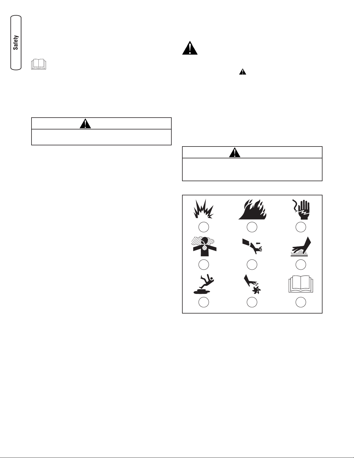
Hazard Symbols and Meanings
A - Explosion F - Hot Surface
B - Fire G - Slippery Surface
C - Electric Shock H - Moving Parts
D - Toxic Fumes J - Read Manual
E - Kickback
4 BRIGGSandSTRATTON.COM
WARNING
The engine exhaust from this product contains chemicals
known to the State of California to cause cancer, birth
defects, or other reproductive harm.
A B C
D E
G H
F
J
CAUTION
These trash pumps are manufactured to pump ONLY water
that is not intended for human consumption.

5
WARNING
Use of trash pump can create puddles and
slippery surfaces.
• Operate trash pump from a stable surface.
• The area should have adequate slopes and drainage to reduce
the possibility of a fall due to slippery surfaces.
WARNING
Fuel and its vapors are extremely flammable and
explosive.
Fire or explosion can cause severe burns or
death.
WHEN ADDING OR DRAINING FUEL
• Turn trash pump OFF and let it cool at least 2 minutes before
removing fuel cap. Loosen cap slowly to relieve pressure in
tank.
• Fill or drain fuel tank outdoors.
• DO NOT overfill tank. Allow space for fuel expansion.
• If fuel spills, wait until it evaporates before starting engine.
• Keep fuel away from sparks, open flames, pilot lights, heat, and
other ignition sources.
• DO NOT light a cigarette or smoke.
WHEN STARTING EQUIPMENT
• Ensure spark plug, muffler, fuel cap, and air cleaner are in place.
• DO NOT crank engine with spark plug removed.
WHEN OPERATING EQUIPMENT
• DO NOT pump flammable liquids, such as fuel or fuel oils.
• This trash pump is not for use in mobile equipment or marine
applications.
• DO NOT tip engine or equipment at angle which causes fuel
to spill.
• Secure trash pump. Loads from hoses may cause tipover.
WHEN TRANSPORTING OR REPAIRING EQUIPMENT
• Transport/repair with fuel tank EMPTY or with fuel shutoff
valve OFF.
• Disconnect spark plug wire.
WHEN STORING FUEL OR EQUIPMENT WITH FUEL IN TANK
• Store away from furnaces, stoves, water heaters, clothes dryers,
or other appliances that have pilot light or other ignition source
because they can ignite fuel vapors.
WARNING
Running engine gives off carbon monoxide, an
odorless, colorless, poison gas.
Breathing carbon monoxide can cause headache,
fatigue, dizziness, vomiting, confusion, seizures,
nausea, fainting or death.
• Operate trash pump ONLY outdoors.
• Keep exhaust gas from entering a confined area through
windows, doors, ventilation intakes, or other openings.
• DO NOT start or run engine indoors or in an enclosed area, even
if windows and doors are open.
WARNING
Unintentional sparking can result in fire or
electric shock.
WHEN ADJUSTING OR MAKING REPAIRS TO YOUR TRASH
PUMP
• Disconnect the spark plug wire from the spark plug and place
the wire where it cannot contact spark plug.
WHEN TESTING FOR ENGINE SPARK
• Use approved spark plug tester.
• DO NOT check for spark with spark plug removed.
6 BRIGGSandSTRATTON.COM
WARNING
Contact with muffler area can result in serious
burns.
Exhaust heat/gases can ignite combustibles,
structures or damage fuel tank causing a fire.
• DO NOT touch hot parts and AVOID hot exhaust gases.
• Allow equipment to cool before touching.
• Keep at least 5 feet (1.5 m) of clearance on all sides of trash
pump including overhead.
• Code of Federal Regulation (CFR) Title 36 Parks, Forests, and
Public Property require equipment powered by an internal
combustion engine to have a spark arrester, maintained in
effective working order, complying to USDA Forest service
standard 5100-1C or later revision. In the State of California a
spark arrester is required under section 4442 of the California
Public resources code. Other states may have similar laws.
WARNING
Starter and other rotating parts can entangle
hands, hair, clothing, or accessories.
• NEVER place hands or body parts inside of running pump or
hoses.
• NEVER operate trash pump without protective housing or
covers.
• DO NOT wear loose clothing, jewelry or anything that may be
caught in the starter or other rotating parts.
• Tie up long hair and remove jewelry.
NOTICE
Improper treatment of trash pump can damage it and
shorten its life.
• If you have questions about intended use, ask dealer or contact
qualified service center.
• Be sure pump chamber is filled with water before starting the
engine. Never run pump without priming.
• Use a non-collapsible hose on the suction side of pump.
• Use trash pump only for intended uses.
• Pumping sea water, beverages, acids, chemical solutions, or any
other liquid that promotes corrosion can damage the pump.
• Ensure all connections are air tight.
• DO NOT obstruct the suction or discharge hose in any way.
• NEVER operate pump without strainer basket connected to end
of suction hose.
• DO NOT exceed suction head maximum of 8m (25 ft.) and total
head of 35.6m (117 ft.). Use shortest suction head possible (see
page 11).
• NEVER allow vehicles to drive over hoses. If a hose must be
positioned across a roadway, use planking on each side of hose
to allow vehicles to pass over without obstructing or collapsing
hose.
• Anchor pump to avoid “walking” or equipment movement,
especially if located near a ditch or edge of open ravine. The
equipment could fall in.
• Keep equipment away from edge of river or lake where it could
cause the bank to collapse.
• DO NOT insert any objects through cooling slots.
• NEVER operate units with broken or missing parts, or without
protective housing or covers.
• DO NOT by-pass any safety device on this machine.
• NEVER move machine by pulling on hoses. Use frame on unit.
• Check fuel system for leaks or signs of deterioration, such as
chafed or spongy hose, loose or missing clamps, or damaged
tank or cap. Correct all defects before operating trash pump.
• This equipment is designed to be used with Briggs & Stratton
Power Products authorized parts ONLY. If equipment is used
with parts that DO NOT comply with minimum specifications,
user assumes all risks and liabilities.
CAUTION
Excessively high operating speeds increase risk of injury
and damage to trash pump.
Excessively low speeds impose a heavy load.
• DO NOT tamper with governed speed.
• DO NOT modify trash pump in any way.
• DO NOT allow unqualified persons or children to operate or
service trash pump.
WARNING
Starter cord kickback (rapid retraction) can result
in bodily injury. Kickback will pull hand and arm
toward engine faster than you can let go.
Broken bones, fractures, bruises, or sprains
could result.
Keep hands and body clear from discharge of
pump.
• When starting engine, pull cord slowly until resistance is felt and
then pull rapidly to avoid kickback.
• Secure discharge hose to avoid whipping.

7
Assembly
Read entire operator’s manual before you attempt
to assemble or operate your new trash pump.
Your trash pump requires some assembly and is ready for
use after it has been properly serviced with the
recommended oil and fuel.
If you have any problems with the assembly of your trash
pump, please call the trash pump helpline at (800) 743-4115.
If calling for assistance, please have the model, revision, and
serial number from the data tag available. See Controls
section for data tag location.
Unpack Trash Pump
1. Remove the parts bag, accessories, and inserts
included with trash pump.
2. Open carton completely by cutting each corner from
top to bottom.
3. Ensure you have all included items prior to assembly.
Items in the carton include:
• Trash pump
• Oil bottle
• Parts bag (which includes the following):
• This operator’s manual
• Owner’s registration card
• Strainer basket and barb
• Hose barb (2)
• Barb cuff (2)
• Rubber seal (2)
• Hose clamp (3)
To prepare your trash pump for operation, you will need to
perform these tasks:
1. Fill out and send in registration card.
2. Add oil to engine crankcase.
3. Add fuel to fuel tank.
4. Attach suction hose.
5. Connect discharge hose (optional).
6. Move trash pump to safe operating location.
7. Prime the trash pump.
8. Locate strainer basket into water source.
Add Engine Oil
1. Place trash pump on a flat, level surface.
2. Clean area around oil fill and remove yellow oil fill cap.
NOTE: See Oil Recommendations in Maintenance section.
Verify provided oil bottle is the correct viscosity for current
ambient temperature.
3. Using oil funnel (optional), slowly pour contents of
provided oil bottle into oil fill opening.
4. Replace oil fill cap and fully tighten.
Add Fuel
Fuel must meet these requirements:
• Clean, fresh, unleaded gasoline.
• A minimum of 87 octane/87 AKI (91 RON). High
altitude use, see High Altitude.
• Gasoline with up to 10% ethanol (gasohol) or up to
15% MTBE (methyl tertiary butyl ether) is acceptable.
To protect the fuel system from gum formation, mix in a fuel
stabilizer when adding fuel. See Storage. All fuel is not the
same. If you experience starting or performance problems
after using fuel, switch to a different fuel provider or change
brands. This engine is certified to operate on gasoline. The
emission control system for this engine is EM (Engine
Modifications).
NOTICE
Improper treatment of trash pump can damage it and
shorten its life.
• DO NOT attempt to crank or start the engine before it has been
properly serviced with the recommended oil. This may result in
an engine failure.
NOTICE
Avoid trash pump damage.
Failure to follow Operator’s Manual for fuel
recommendations voids warranty.
• DO NOT use unapproved gasoline such as E85.
• DO NOT mix oil in gasoline.
• DO NOT modify engine to run on alternate fuels.
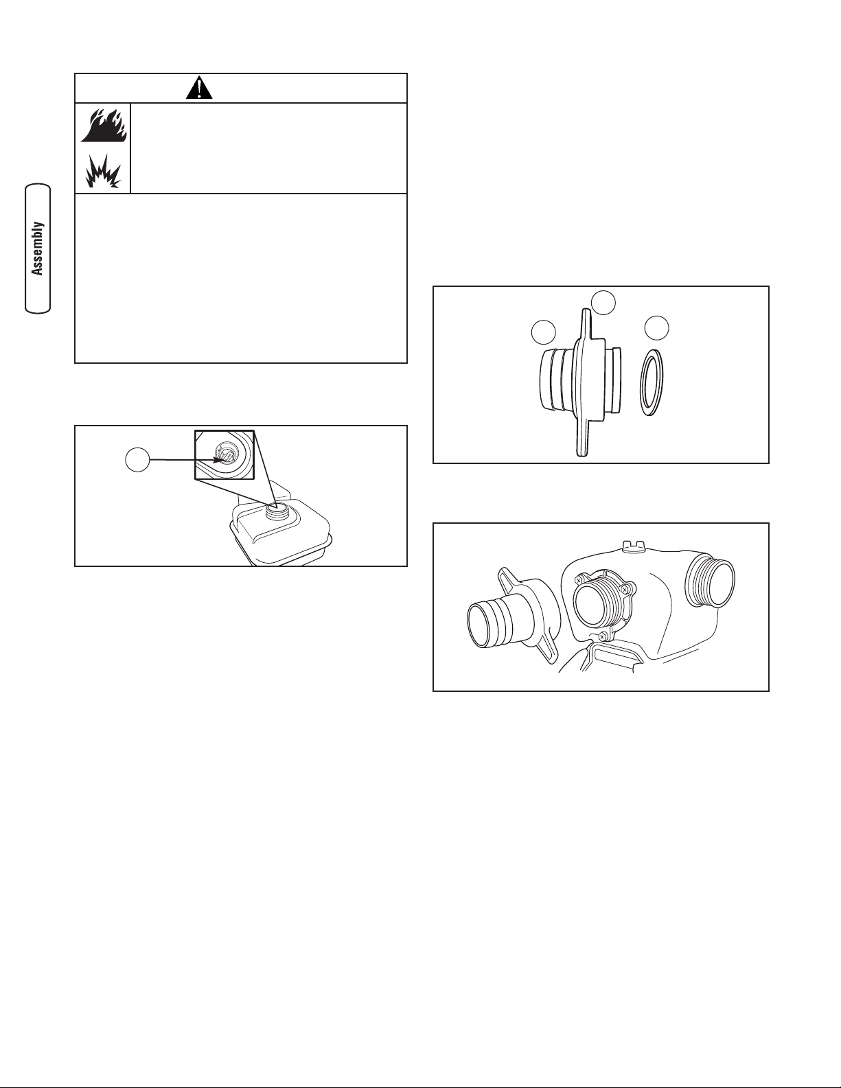
1. Clean area around fuel fill cap, remove cap.
2. Slowly add regular unleaded fuel to fuel tank. Fill to red
level indicator (A). Be careful not to overfill.
3. Install fuel cap and let any spilled fuel evaporate before
starting engine.
High Altitude
At altitudes over 5,000 feet (1524 meters), a minimum
85 octane / 85 AKI (89 RON) gasoline is acceptable. To
remain emissions compliant, high altitude adjustment is
required. Operation without this adjustment will cause
decreased performance, increased fuel consumption, and
increased emissions. See an Authorized Briggs & Stratton
dealer for high altitude adjustment information. Operation of
the engine at altitudes below 2,500 feet (762 meters) with
the high altitude kit is not recommended.
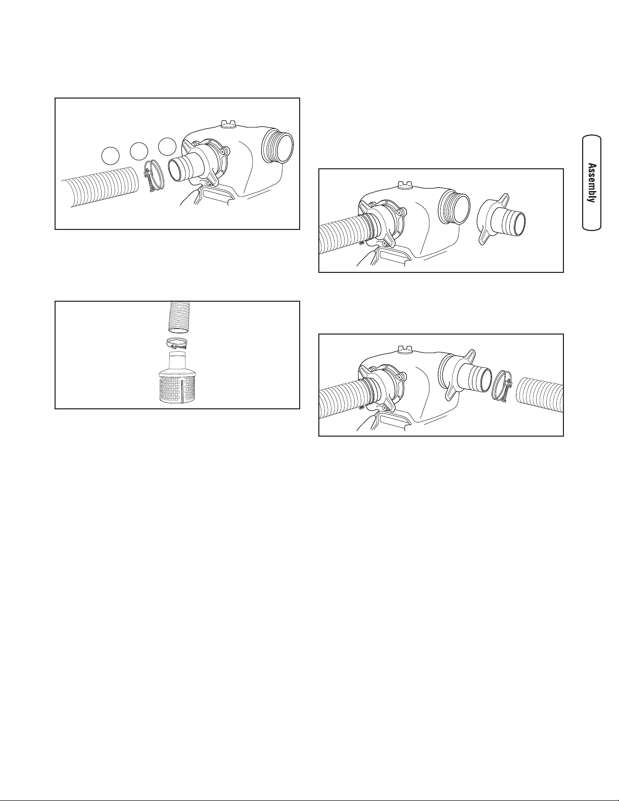
Attach Suction Hose
You will need the following tool to install the hoses to the
trash pump:
• 1/4" or 6mm standard screwdriver
Connect Suction Hose to Pump
Use a commercially available hose. The suction hose must
be reinforced with a non-collapsible wall or braided material.
DO NOT use a hose with an inside diameter smaller than the
pumps suction port size.
1. Slide barb cuff (B) over hose barb (C). Insert rubber
seal (D) into end of barb cuff.
2. Screw hose barb assembly onto pump in clockwise
rotation until hose barb assembly is tightened securely.
8 BRIGGSandSTRATTON.COM
WARNING
Fuel and its vapors are extremely flammable and
explosive.
Fire or explosion can cause severe burns or
death.
WHEN ADDING FUEL
• Turn trash pump OFF and let it cool at least 2 minutes before
removing fuel cap. Loosen cap slowly to relieve pressure in
tank.
• Fill fuel tank outdoors.
• DO NOT overfill tank. Allow space for fuel expansion.
• If fuel spills, wait until it evaporates before starting engine.
• Keep fuel away from sparks, open flames, pilot lights, heat, and
other ignition sources.
• DO NOT light a cigarette or smoke.
A
D
B
C
9
3. Slide hose clamp (A) over end of hose (B). Slide
suction hose onto hose barb (C). Tighten hose clamp
securely using a standard 1/4” (6mm) screwdriver.
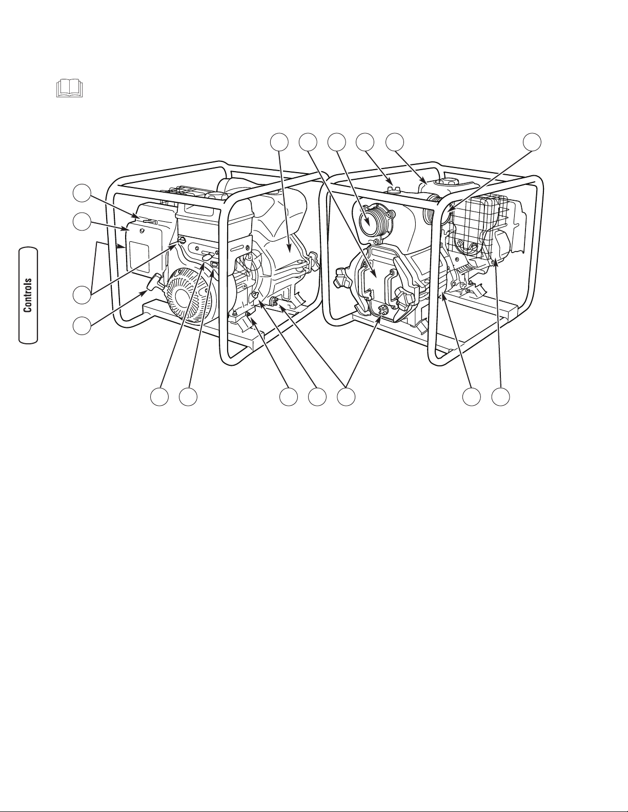
Attach Suction Hose to Strainer Basket
Slide hose clamp over hose. Attach open end of suction hose
to strainer hose barb. Tighten hose clamp securely using a
standard 1/4” (6mm) screwdriver.
Connect Discharge Hose (Optional)
If desired, use a commercially available hose. DO NOT use a
hose with an inside diameter smaller than the pump’s
discharge port size.
1. Slide barb cuff over hose barb. Insert rubber seal into
end of barb cuff as shown earlier.
2. Screw hose barb assembly onto pump in clockwise
rotation until hose barb assembly is tightened securely.
3. Slide hose clamp over end of discharge hose. Slide
discharge hose onto hose barb. Tighten hose clamp
securely using a standard 1/4” (6mm) screwdriver.
C
A
B
10 BRIGGSandSTRATTON.COM
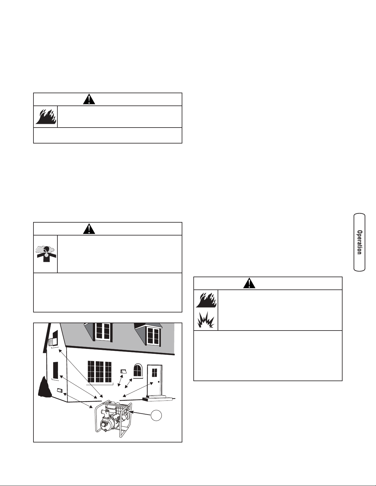
A - Data Tag — Provides model and serial number of trash
pump. Please have these readily available if calling for
assistance.
B - Pump Faceplate — Remove to clean impeller.
C - Suction Inlet — Connect reinforced suction hose here.
D - Priming Plug — Fill pump with water here to prime
pump before starting.
E - Fuel Tank — Fill tank with regular unleaded fuel. Always
leave room for fuel expansion.
F - Discharge Outlet — Connect discharge hose here.
G - Choke Lever — Prepares a cold engine for starting.
H - Air Cleaner — Protects engine by filtering dust and
debris out of intake air.
J - Fuel Shutoff Valve — Used to turn fuel supply on and off
to engine.
Model 073017 — located behind the air cleaner on the
carburetor.
Model 073018 — located to the left of the engine speed
lever on the engine control panel.
K - Recoil Starter — Used for starting the engine manually.
L - Engine Speed Lever — Used to adjust engine speed to
control pump output.
M - On/Off Switch — Set this switch to “On” before using
recoil starter. Set switch to “Off” to stop a running
engine.
N - Oil Drain — Drain engine oil here.
P - Oil Fill — Check and add engine oil here.
Q - Water Drain Plugs — Remove to drain water from pump
and flush internal components with clean water.
S - Pump Chamber — Be sure to fill with water before
starting.
T - Engine Information — Stamped on valve cover. Provides
model, type and trim number of engine. Please have
these readily available when calling for assistance.
Item Not Shown:
Strainer Basket — Used to limit passage of abrasive
materials into the pump.
10 BRIGGSandSTRATTON.COM
K
H
J
G
Unit may vary slightly from that shown
Features and Controls
Read this Operator’s Manual and safety rules before operating your trash pump.
Compare the illustrations with your trash pump, to familiarize yourself with the locations of various controls and
adjustments. Save this manual for future reference.
M P S T
DCB E FA
L QN
11
Operation
If you have any problems operating your trash pump, please
call the trash pump helpline at (800) 743-4115.
Safe Operating Considerations
Clearances and Air Movement
Place trash pump outdoors in an area that will not
accumulate deadly exhaust gas. DO NOT place trash pump
where exhaust gas (A) could accumulate and enter inside or
be drawn into a potentially occupied building. Ensure
exhaust gas is kept away from any windows, doors,
ventilation intakes, or other openings that can allow exhaust
gas to collect in a confined area. Prevailing winds and air
currents should be taken into consideration when positioning
trash pump.
What is “Head”?
Head refers to the height of a column of water that can be
delivered by the discharge of the pump.
Suction Head is the vertical distance between the center of
the pump and the surface of the liquid on the suction side of
the pump. May also be referred to as “suction lift”. The
atmospheric pressure of 14.7 psi at sea level limits suction
head lift to less than approximately 26 feet for any pump.
Discharge Head is the vertical distance between the pump’s
discharge port and the point of discharge, which is the liquid
surface if the hose is submerged or pumping into the bottom
of a tank.
Total Head is the sum of the suction head value plus the
discharge head value.
As water pumping height increases, pump output decreases.
The length, type, and size of the suction and discharge hoses
can also significantly affect pump output.
It is important for the suction operation to be the shorter
part of the total pumping action. This will decrease the
priming time and improve pump performance by increasing
the discharge head.
Suction head is a maximum of 25 feet and discharge head
should be a maximum of 92 feet. Total head can not be more
than 117 feet as shown on next page.
Move Trash Pump to Safe Operating Location
For best pump performance, locate the pump on a flat, level
surface as close as possible to the water to be pumped.
Secure trash pump to avoid tipover. Use hoses that are no
longer than necessary.
IMPORTANT: Direct open end of discharge hose away from
home, electrical devices or anything not desired to get wet.
WARNING
Exhaust heat/gases can ignite combustibles,
structures or damage fuel tank causing a fire.
• Keep at least 5 ft. (1.5 m) clearance on all sides of trash pump
including overhead.
WARNING
Running engine gives off carbon monoxide, an
odorless, colorless, poison gas.
Breathing carbon monoxide can cause headache,
fatigue, dizziness, vomiting, confusion, seizures,
nausea, fainting or death.
• Operate trash pump ONLY outdoors.
• Keep exhaust gas from entering a confined area through
windows, doors, ventilation intakes, or other openings.
• DO NOT start or run engine indoors or in an enclosed area, even
if windows and doors are open.
A
WARNING
Fuel and its vapors are extremely flammable and
explosive.
Fire or explosion can cause severe burns or
death.
WHEN OPERATING EQUIPMENT
• This trash pump is not for use in mobile equipment or marine
applications.
• DO NOT tip engine or equipment at angle which causes fuel to
spill.
• Secure trash pump. Loads from hoses may cause tip over.

Prime the Trash Pump
1. Remove priming plug from top of pump.
2. Fill pump with clean, clear water up to top of discharge
outlet.
3. Replace priming plug.
Locate Strainer Basket Into Water Source
Place strainer basket into water to be pumped. Basket must
be fully immersed in water.
12 BRIGGSandSTRATTON.COM
Discharge Head
- 92 feet (28m)
Maximum
Suction Head
- 25 feet (8m)
Maximum
Total Head
- 117 feet (35.6m)
Maximum
NOTICE
Improper treatment of trash pump can damage it and
shorten its life.
• Be sure pump chamber is filled with water before starting the
engine. NEVER run pump without priming.
NOTICE
Improper treatment of trash pump can damage it and
shorten its life.
• NEVER operate pump without strainer connected to end of
suction hose.
• Keep strainer out of sand or silt, place in bucket or on stones.
• DO NOT let pump run dry or damage to seals may result.
13
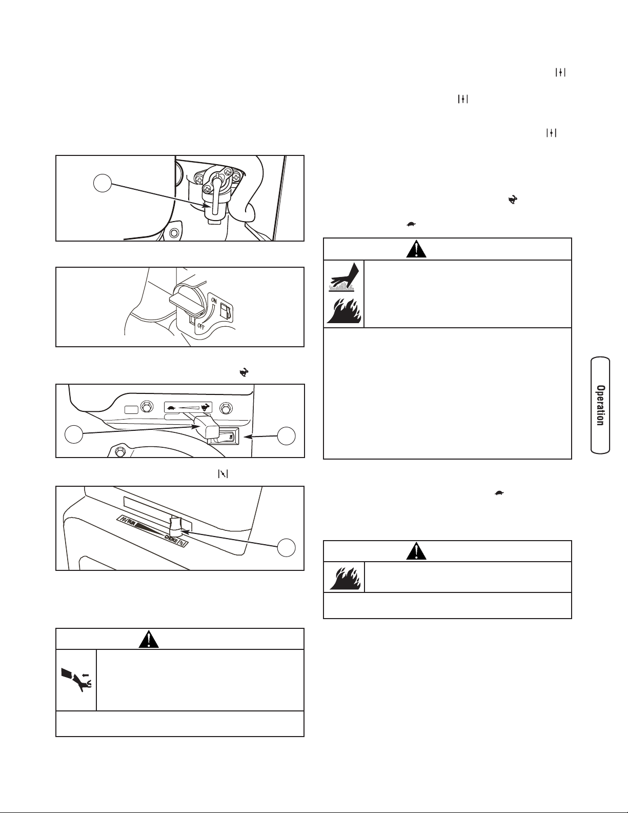
Starting the Trash Pump
Use the following start instructions:
1. Make sure unit is on a flat, level surface and pump
chamber is primed.
2. Model 073017 — Turn fuel valve (A) to “On” position.
The fuel valve handle will be vertical (pointing toward
the ground).
Model 073018 — Turn fuel valve to “On” position.
3. Push ON/OFF switch (B) to “On” position.
4. Move engine speed lever (C) to “Fast” ( ) position.
5. Move choke lever (D) to “Choke” ( ) position.
6. Grasp recoil handle and pull slowly until slight
resistance is felt. Then pull handle rapidly to overcome
compression, prevent kickback and start engine.
IMPORTANT: If excessive fuel is present in the air/fuel mixture
causing a “flooded” condition, move choke lever to “Run” ( )
position and pull handle repeatedly until engine starts.
7. Move choke lever to “Run” ( ) position a short
distance at a time over several seconds in warm weather
or minutes in cold weather. Let engine run smoothly
before each change. Operate with choke in “Run” ( )
position.
IMPORTANT: It may take a few minutes for trash pump to
begin pumping water.
Pump output is controlled by adjusting engine speed.
Moving the engine speed lever in the “Fast” ( ) direction
will increase pump output, and moving the engine speed
lever in the “Slow” ( ) direction will decrease pump output.
Stopping the Trash Pump
1. Move engine speed lever to “Slow” ( ) position.
2. Push on/off switch to “Off” position.
3. Turn fuel valve to “Off” position.
WARNING
Contact with muffler area can result in serious
burns.
Exhaust heat/gases can ignite combustibles,
structures or damage fuel tank causing a fire.
• DO NOT touch hot parts and AVOID hot exhaust gases.
• Allow equipment to cool before touching.
• Keep at least 5 feet (1.5 m) of clearance on all sides of trash
pump including overhead.
• Code of Federal Regulation (CFR) Title 36 Parks, Forests, and
Public Property require equipment powered by an internal
combustion engine to have a spark arrester, maintained in
effective working order, complying to USDA Forest service
standard 5100-1C or later revision. In the State of California a
spark arrester is required under section 4442 of the California
Public resources code. Other states may have similar laws.
WARNING
Starter cord kickback (rapid retraction) can result
in bodily injury. Kickback will pull hand and arm
toward engine faster than you can let go.
Broken bones, fractures, bruises, or sprains
could result.
• When starting engine, pull cord slowly until resistance is felt and
then pull rapidly to avoid kickback.
A
B
C
D
WARNING
Backfire, fire or engine damage could occur.
• DO NOT stop engine by moving choke control to “Choke”
position.

After Each Use
Water should not remain in the pump chamber for long
periods of time. Sediments and minerals can deposit on
pump parts and cause poor pump performance. Follow these
procedures after every use:
Flush and Drain Trash Pump and Clean the Impeller
1. Stop engine following instructions in Stopping the
Trash Pump.
2. Disconnect the spark plug wire from the spark plug and
place the wire where it cannot contact spark plug.
3. Disconnect and drain suction and discharge hoses.
4. Remove priming plug from top of pump and fill with
clean water.
5. Remove both drain plugs at bottom of pump.
6. Replace all plugs and finger tighten.
7. Loosen the two large triangular knobs (A), inserting a
tool in the grooves on the knobs to assist with leverage.
8. Swing the faceplate clamps (B) to the side.
9. Remove the faceplate from the pump chamber.
10. Clean out any debris inside the impeller (C) and the
volute (D). The volute is bolted to the inside of the
pump faceplate, and should not need to be removed.
A garden hose can be used to flush out either area.
11. To ensure a good seal, clean the sealing surfaces (E)in
the pump chamber and the o-rings on the faceplate (F)
before reinstalling the faceplate.
12. Reinstall the faceplate with the drain plug at the
bottom.
13. Bring the faceplate clamps back to the front, fitting
them securely onto the faceplate.
14. Screw down the two large triangular knobs, inserting a
tool in the grooves on the knobs to tighten firmly.
14 BRIGGSandSTRATTON.COM
WARNING
Unintentional sparking can result in fire or
electric shock.
• NEVER pull recoil starter handle with spark plug removed.
B
A
DC
E F
15
Maintenance
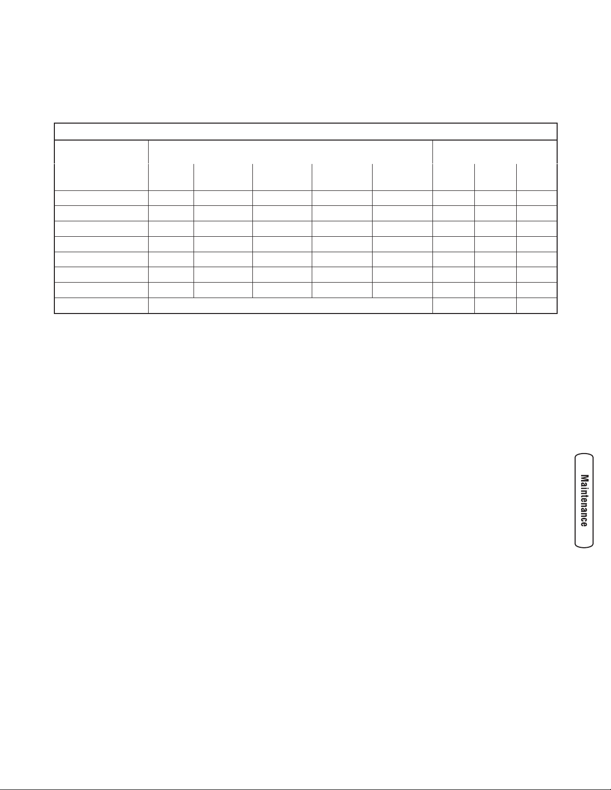
Maintenance Schedule
Follow the hourly or calendar intervals, whichever occurs first. More frequent service is required when operating in adverse
conditions noted below.
1
Change oil after the first (5) operating hours and every 50 hours or every year, whichever occurs first, thereafter. Change oil sooner when operating under dirty or dusty conditions.
2
Replace more often under dirty or dusty conditions.
3
Model 073018 only.
General Recommendations
Regular maintenance will improve the performance and
extend the life of the trash pump. See any authorized Briggs
& Stratton dealer for service.
The trash pump’s warranty does not cover items that have
been subjected to operator abuse or negligence. To receive
full value from the warranty, the operator must maintain
trash pump as instructed in this manual.
Some adjustments will need to be made periodically to
properly maintain your trash pump.
All service and adjustments should be made at least once
each season. Follow the requirements in the Maintenance
Schedule chart above.
NOTE: Once a year you should clean or replace the spark
plug and replace the air filter. A new spark plug and clean air
filter assure proper fuel-air mixture and help your engine run
better and last longer.
Emissions Control
Maintenance, replacement, or repair of the emissions
control devices and systems may be performed by any
non-road engine repair establishment or individual.
However, to obtain ”no charge” emissions control service,
the work must be performed by a factory authorized dealer.
See the Emissions Warranty.
Trash Pump Maintenance
Maintenance consists of keeping the trash pump clean. Store
the unit in a clean dry environment where it will not be
exposed to excessive dust, dirt, moisture or any corrosive
vapors. Cooling air slots in the trash pumps engine must not
become clogged with dirt, leaves or any other foreign
material.
NOTE: DO NOT use a garden hose to clean trash pumps
engine. Water can enter engine fuel system and cause
problems.
Maintenance Schedule - Fill in Dates as You Complete Regular Service
Maintenance Task Service Intervals Service Dates
Before
Each Use
Every 25 Hours
or Yearly
Every 50 Hours
or Yearly
Every 100
Hours or Yearly
Every 250
Hours or Yearly
Clean debris
X
Check oil level
X
Change engine oil
X
1
Service air cleaner
X
2
Service spark plug
X
Clean cooling system
X
2
Check valve clearance
X
3
Prepare for storage
If unit is to remain idle for longer than 30 days.
16 BRIGGSandSTRATTON.COM
Cleaning
Daily or before use, look around and underneath trash pump
for signs of oil or fuel leaks. Clean accumulated debris from
inside and outside trash pump. Keep linkage, spring and
other engine controls clean. Keep area around and behind
muffler free from any combustible debris. Use low pressure
air (not to exceed 25 psi) to blow away dirt. Inspect cooling air
slots and opening on trash pump. These openings must be
kept clean and unobstructed.
Engine parts should be kept clean to reduce the risk of
overheating and ignition of accumulated debris.
• Use a damp cloth to wipe exterior surfaces clean.
• Use a soft bristle brush to loosen caked on dirt or oil.
• Use a vacuum cleaner to pick up loose dirt and debris.
Remove silt and sludge buildup in pump body.
• Follow the instructions in Flush and Drain Trash Pump
and Clean the Impeller.
Engine Maintenance
Oil
Oil Recommendations
We recommend the use of Briggs & Stratton Warranty
Certified oils for best performance. Other high-quality
detergent oils are acceptable if classified for service SF, SG,
SH, SJ or higher. DO NOT use special additives.
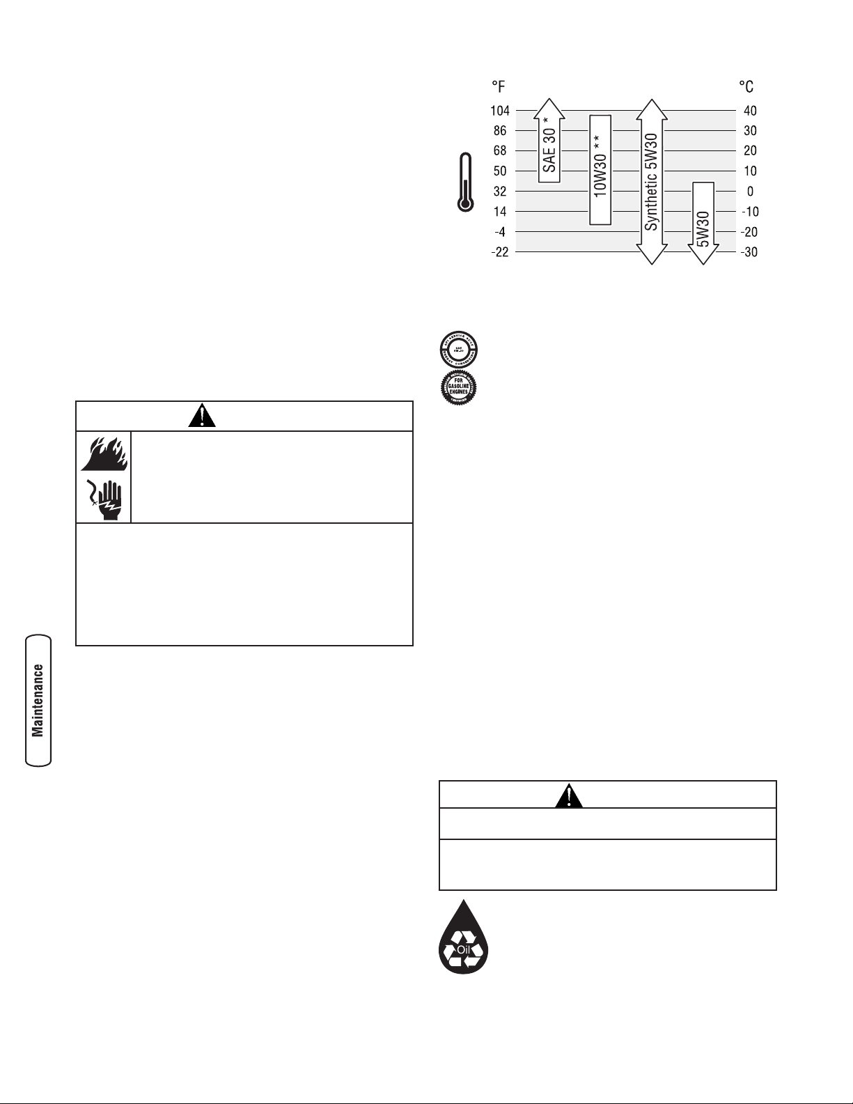
Outdoor temperatures determine the proper oil viscosity for
the engine. Use the chart to select the best viscosity for the
outdoor temperature range expected.
* Below 40°F (4°C) the use of SAE 30 will result in hard starting.
** Above 80°F (27°C) the use of 10W30 may cause increased oil
consumption. Check oil level more frequently.
NOTE: Synthetic oil meeting ILSAC GF-2, API
certification mark and API service symbol with
“SJ/CF ENERGY CONSERVING” or higher, is an
acceptable oil at all temperatures. Use of synthetic
oil does not alter required oil change intervals.
Checking Oil Level
Oil level should be checked prior to each use or at least
every 5 hours of operation. Keep oil level maintained.
1. Make sure trash pump is on a level surface.
2. Clean area around oil fill and remove oil fill cap.
3. Verify oil is at the point of overflowing at oil fill opening.
4. Replace and tighten oil fill cap.
Adding Engine Oil
1. Make sure trash pump is on a level surface.
2. Check oil level as described in Checking Oil Level.
3. If needed, slowly pour oil into oil fill opening to the
point of overflowing at oil fill.
4. Replace and tighten oil fill cap.
Changing Engine Oil
Change the oil after the first 5 hours of operation. Change oil
every 50 hours thereafter. If you are using your trash pump
under extremely dirty or dusty conditions, or in extremely
hot weather, change the oil more often.
KEEP OUT OF REACH OF CHILDREN. DON’T
POLLUTE. CONSERVE RESOURCES. RETURN
USED OIL TO COLLECTION CENTERS.
WARNING
Unintentional sparking can result in fire or
electric shock.
WHEN ADJUSTING OR MAKING REPAIRS TO YOUR TRASH
PUMP
• Disconnect the spark plug wire from the spark plug and place
the wire where it cannot contact spark plug.
WHEN TESTING FOR ENGINE SPARK
• Use approved spark plug tester.
• DO NOT check for spark with spark plug removed.
CAUTION
Avoid prolonged or repeated skin contact with used motor
oil.
• Used motor oil has been shown to cause skin cancer in certain
laboratory animals.
• Thoroughly wash exposed areas with soap and water.
17
Change the oil while the engine is still warm from running,
as follows:
1. Make sure trash pump is on a level surface.
2. Disconnect the spark plug wire from the spark plug and
place the wire where it cannot contact spark plug.
3. Clean area around oil drain plug (A). The oil drain plug is
located at base of engine, opposite carburetor.
4. Remove oil drain plug and drain oil completely into a
suitable container.
5. Reinstall oil drain plug and tighten securely. Remove oil
fill cap.
6. Slowly pour oil into oil fill opening (B) to the point of
overflowing (C) at oil fill cap. DO NOT overfill.
7. Reinstall oil fill cap. Finger tighten cap securely.
8. Wipe up any spilled oil.
Service Air Cleaner
Your engine will not run properly and may be damaged if
you run it with a dirty air cleaner.
Clean or replace the air cleaner every 25 hours of operation
or once each year, whichever comes first. Clean or replace
more often if operating under dirty or dusty conditions.
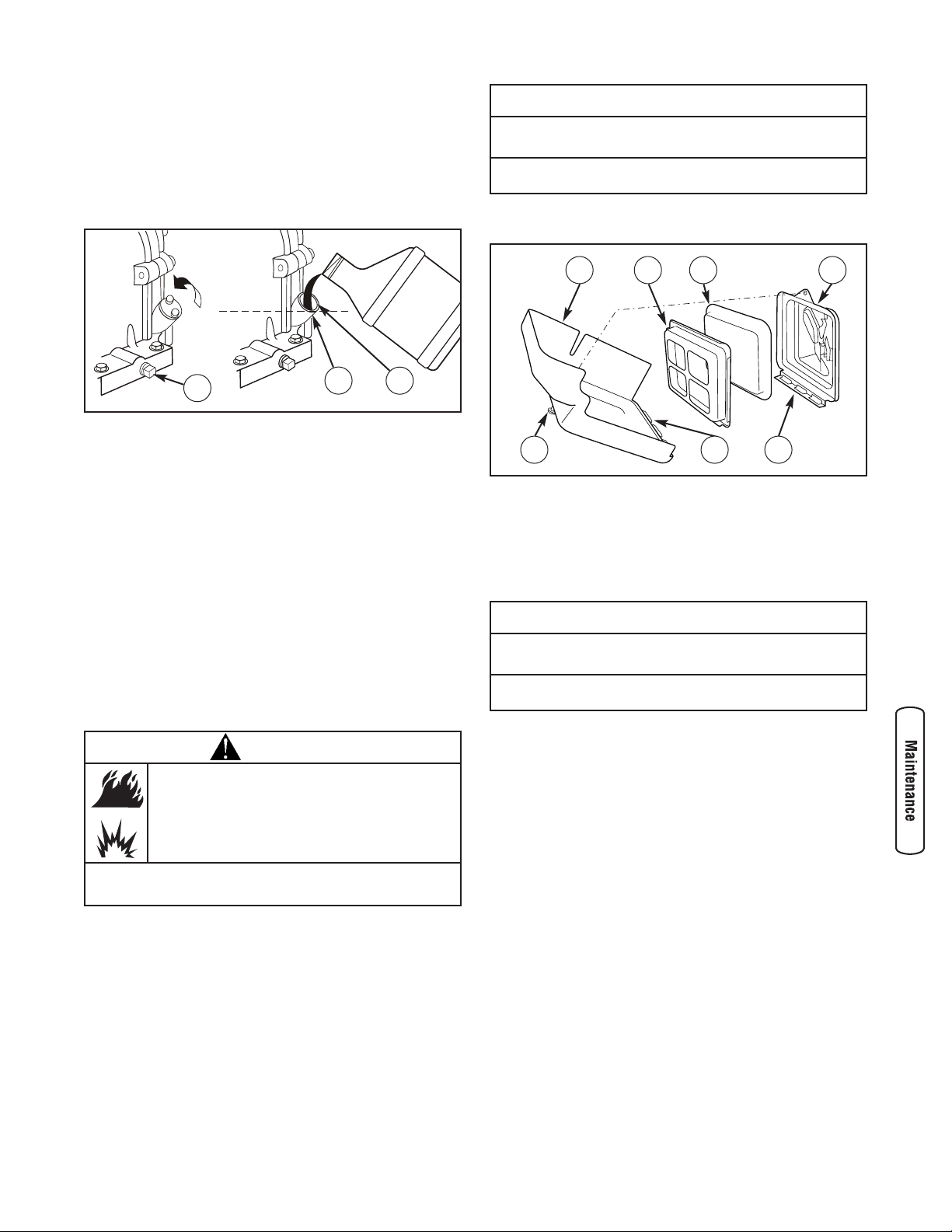
To service the air cleaner, follow these steps:
1. Loosen screw (D) and tilt cover (E) down.
2. Remove air cleaner assembly from cover.
3. Carefully separate foam air cleaner (F) from air cleaner
plate (G).
4. Wash foam air cleaner in liquid detergent and water.
To dry, squeeze foam air cleaner in a clean cloth.
5. Saturate foam air cleaner with clean engine oil.
To remove excess oil, squeeze foam air cleaner in a
clean cloth.
6. Reinstall cleaned and oiled foam air cleaner in
air cleaner plate.
7. Firmly fit air cleaner assembly into cover.
8. Insert cover’s tabs (H) into slots (J) in bottom of base (K).
9. Tilt cover up and tighten screw securely to base.
NOTICE
DO NOT use pressurized air or solvents to clean the foam
air cleaner.
• Pressurized air can damage the foam air cleaner and solvents
will dissolve the foam air cleaner.
WARNING
Fuel and its vapors are extremely flammable and
explosive.
Fire or explosion can cause severe burns or
death.
• NEVER start or run the engine with the air cleaner assembly or
the foam air cleaner removed.
F
D
E
H
G K
J
A
B
C
NOTICE
DO NOT use pressurized air or solvents to clean the foam
air cleaner.
• Pressurized air can damage the foam air cleaner and solvents
will dissolve the foam air cleaner.
18 BRIGGSandSTRATTON.COM
Service Spark Plug
Change the spark plug every 100 hours of operation or once
each year, whichever comes first. This will help your engine
to start easier and run better.
1. Clean area around spark plug.
2. Remove and inspect spark plug.
3. Check electrode gap with wire feeler gauge and set
spark plug gap to 0.030 inch (0.76mm) if necessary.
4. Replace spark plug if electrodes are pitted, burned or
porcelain is cracked. Use the recommended
replacement plug. See Specifications.
5. Install spark plug and tighten firmly.
Clean Spark Arrester Screen
If you use your trash pump on any forest-covered, brushcovered, or grass-covered unimproved land, it must have a
spark arrester. The spark arrester must be maintained in
good condition by the owner/operator.
If the engine has been running, the muffler will be very hot.
Allow the muffler to cool before servicing the spark arrester.
1. Remove spark arrester screen for cleaning and inspection.
2. Inspect screen and replace if torn, perforated or
otherwise damaged. DO NOT use a defective screen. If
screen is not damaged, clean it with commercial solvent.
3. Reattach spark arrester screen to muffler.
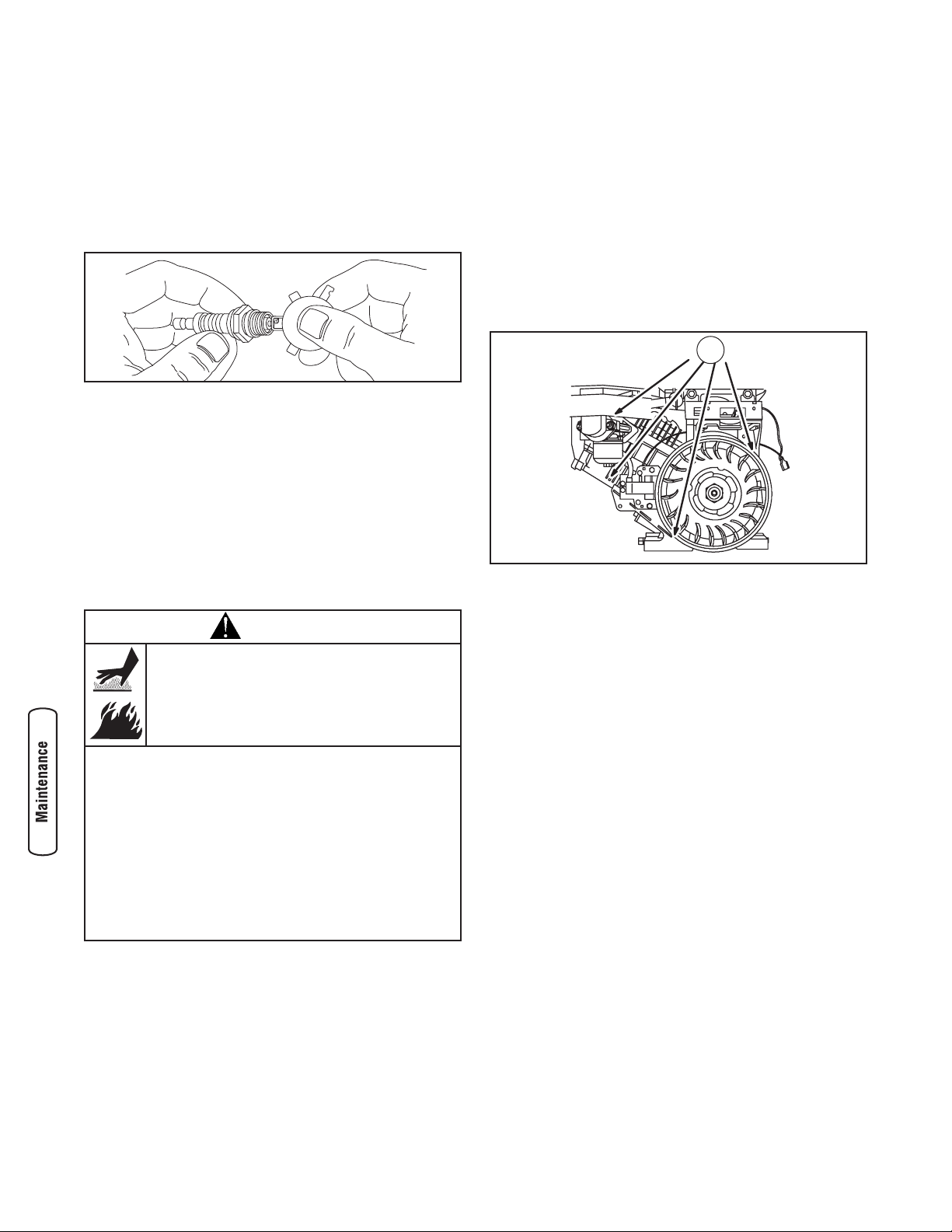
Air Cooling System
Over time debris may accumulate in cylinder cooling fins and
cannot be removed without partial engine disassembly. For
this reason, we recommend you have an authorized Briggs &
Stratton service dealer clean the cooling system (A) per
recommended intervals (see Maintenance Schedule in
beginning of Maintenance section). Equally important is to
keep top of engine free from debris. See Clean Debris.
Check Valve Clearance (Model 073018 Only)
Regular valve clearance check and adjustment will improve
performance and extend engine life. This procedure cannot
be done without partial engine disassembly and the use of
special tools. For this reason we recommend that you have
an authorized dealer check and adjust valve clearance at
250 hours or as recommended (see Maintenance Schedule in
the Maintenance section).
WARNING
Contact with muffler area can result in serious
burns.
Exhaust heat/gases can ignite combustibles,
structures or damage fuel tank causing a fire.
• DO NOT touch hot parts and AVOID hot exhaust gases.
• Allow equipment to cool before touching.
• Keep at least 5 feet (1.5 m) of clearance on all sides of trash
pump including overhead.
• Code of Federal Regulation (CFR) Title 36 Parks, Forests, and
Public Property require equipment powered by an internal
combustion engine to have a spark arrester, maintained in
effective working order, complying to USDA Forest service
standard 5100-1C or later revision. In the State of California a
spark arrester is required under section 4442 of the California
Public resources code. Other states may have similar laws.
A
19
Storage
The trash pump should be started at least once every seven
days and allowed to run at least 30 minutes. If this cannot be
done and you must store the unit for more than 30 days, use
the following information as a guide to prepare it for storage.
Long Term Storage Instructions
It is important to prevent gum deposits from forming in
essential fuel system parts, such as the carburetor, fuel filter,
fuel hose or tank during storage. Also, experience indicates
that alcohol-blended fuels (called gasohol, ethanol or
methanol) can attract moisture, which leads to separation
and formation of acids during storage. Acidic fuel can
damage the fuel system of an engine while in storage.
Protect Fuel System
Fuel Additive:
Fuel can become stale when stored over 30 days. Stale fuel
causes acid and gum deposits to form in the fuel system or
on essential carburetor parts. To keep fuel fresh, use Briggs
& Stratton FRESH START™ fuel stabilizer, available as a
liquid additive or a drip concentrate cartridge.
There is no need to drain gasoline from the engine if a fuel
stabilizer is added according to instructions. Run the engine
for 2 minutes to circulate the stabilizer throughout the fuel
system. The engine and fuel can then be stored up to
24 months.
If gasoline in the engine has not been treated with a fuel
stabilizer, it must be drained into an approved container. Run
the engine until it stops from lack of fuel. The use of a fuel
stabilizer in the storage container is recommended to
maintain freshness.
Change Engine Oil
While engine is still warm, drain oil from crankcase. Refill
with recommended grade. See Changing Engine Oil in Engine
Maintenance.
Oil Cylinder Bore
• Remove spark plug and pour about 1/2 ounce (15 ml)
of clean engine oil into the cylinder.
• Install spark plug and pull starter handle slowly to
distribute oil.
Trash Pump
1. Drain trash pump as described in Flush and Drain Trash
Pump.
2. Clean trash pump as described in Cleaning.
3. Check that openings on trash pump are open and
unobstructed.
Other Storage Tips
1. DO NOT store fuel from one season to another unless it
has been treated as described in Protect Fuel System.
2. Replace fuel can if it starts to rust. Contaminated fuel
will cause engine problems.
3. Cover unit with a suitable protective cover that does not
retain moisture.
4. Store trash pump in clean, dry area.
WARNING
Fuel and its vapors are extremely flammable and
explosive.
Fire or explosion can cause severe burns or
death.
WHEN STORING FUEL OR EQUIPMENT WITH FUEL IN TANK
• Store away from furnaces, stoves, water heaters, clothes dryers,
or other appliances that have pilot light or other ignition source
because they can ignite fuel vapors.
WHEN DRAINING FUEL
• Turn trash pump OFF and let it cool at least 2 minutes before
removing fuel cap. Loosen cap slowly to relieve pressure in
tank.
• Drain fuel tank outdoors.
• Keep fuel away from sparks, open flames, pilot lights, heat, and
other ignition sources.
• DO NOT light a cigarette or smoke.
WARNING
Unintentional sparking can result in fire or
electric shock.
• NEVER pull starter handle with spark plug removed.
WARNING
Storage covers can be flammable.
• DO NOT place a storage cover over a hot trash pump.
• Let equipment cool for a sufficient time before placing the cover
on the equipment.

20 BRIGGSandSTRATTON.COM
Troubleshooting
Problem Cause Correction
No pump output or low pump
output when trash pump is
running.
1. Pump not primed.
2. Suction hose restricted, collapsed,
damaged, too long, or diameter too
small.
3. Strainer not completely under water.
4. Air leak at suction hose connector.
5. Strainer clogged.
6. Impeller clogged.
7. Discharge hose restricted, damaged, too
long, or diameter too small.
8. Excessive or marginal head.
9. Engine speed lever is in “Slow” ( )
position.
1. Fill pump chamber with water and
prime pump.
2. Replace suction hose.
3. Sink the strainer and the end of
suction hose completely under water.
4. Replace sealing washer if missing or
damaged. Tighten hose connector
and clamp.
5. Clean debris from strainer.
6. Clean impeller. See After Each Use.
7. Replace discharge hose.
8. Relocate pump and/or hoses to
reduce head.
9. Move engine speed lever to
“Fast” ( ) position.
Engine will not start; lacks
power; starts and runs rough;
or "hunts" or falters.
1. Rocker switch set to "Off".
2. Fuel valve is in "Off" position.
3. Dirty air cleaner.
4. Out of fuel.
5. Stale or contaminated fuel or water in
fuel.
6. Spark plug wire not connected to spark
plug.
7. Bad spark plug.
8. Excessive fuel is present in the air/fuel
mixture causing a “flooded” condition.
9. Carburetor is out of adjustment.
1. Set switch to "On".
2. Turn fuel valve to "On" position.
3. Clean or replace air cleaner.
4. Wait two minutes and fill fuel tank.
5. Drain fuel tank and carburetor; fill
with fresh fuel.
6. Connect wire to spark plug.
7. Replace spark plug.
8. Wait 5 minutes and re-crank engine.
9. Contact Authorized service facility.
Engine shuts down when
running.
Out of fuel. Wait two minutes and fill fuel tank.

Warranties
Emissions Control System Warranty
Briggs & Stratton Corporation (B&S), the California Air
Resources Board (CARB) and the United States
Environmental Protection Agency (U.S. EPA)
Emissions Control System Warranty Statement (Owner’s
Defect Warranty Rights and Obligations)
California, United States and Canada Emissions Control
Defects Warranty Statement
The California Air Resources Board (CARB), U.S. EPA and
B&S are pleased to explain the Emissions Control System
Warranty on your small off-road engine (SORE). In
California, new small off-road engines model year 2006 and
later must be designed, built and equipped to meet the
State’s stringent anti-smog standards. Elsewhere in the
United States, new non-road, spark-ignition engines certified
for model year 1997 and later must meet similar standards
set forth by the U.S. EPA. B&S must warrant the emissions
control system on your engine for the periods of time listed
below, provided there has been no abuse, neglect or
improper maintenance of your small off-road engine.
Your emissions control system includes parts such as the
carburetor, air cleaner, ignition system, fuel line, muffler and
catalytic converter. Also included may be connectors and
other emissions related assemblies.
Where a warrantable condition exists, B&S will repair your
small off-road engine at no cost to you including diagnosis,
parts and labor.
Briggs & Stratton Emissions Control Defects Warranty
Coverage
Small off-road engines are warranted relative to emissions
control parts defects for a period of two years, subject to
provisions set forth below. If any covered part on your
engine is defective, the part will be repaired or replaced by
B&S.
Owner’s Warranty Responsibilities
As the small off-road engine owner, you are responsible for
the performance of the required maintenance listed in your
Operating and Maintenance Instructions. B&S recommends
that you retain all your receipts covering maintenance on
your small off-road engine, but B&S cannot deny warranty
solely for the lack of receipts or for your failure to ensure the
performance of all scheduled maintenance.
As the small off-road engine owner, you should however be
aware that B&S may deny you warranty coverage if your
small off-road engine or a part has failed due to abuse,
neglect, improper maintenance or unapproved modifications.
You are responsible for presenting your small off-road engine
to an Authorized B&S Service Dealer as soon as a problem
exists. The undisputed warranty repairs should be completed
in a reasonable amount of time, not to exceed 30 days.
If you have any questions regarding your warranty rights and
responsibilities, you should contact a B&S Service
Representative at (414) 259-5262.
The emissions warranty is a defects warranty. Defects are
judged on normal engine performance. The warranty is not
related to an in-use emissions test.
Briggs & Stratton Emissions Control Defects Warranty
Provisions
The following are specific provisions relative to your
Emissions Control Defects Warranty Coverage. It is in
addition to the B&S engine warranty for non-regulated
engines found in the Operator’s Manual.
1. Warranted Parts
Coverage under this warranty extends only to the parts
listed below (the emissions control systems parts) to
the extent these parts were present on the engine
purchased.
a. Fuel Metering System
• Cold start enrichment system (soft choke)
• Carburetor and internal parts
• Fuel Pump
• Fuel line, fuel line fittings, clamps
• Fuel tank, cap and tether
• Carbon canister
b. Air Induction System
• Air cleaner
• Intake manifold
• Purge and vent line
c. Ignition System
• Spark plug(s)
• Magneto ignition system
d. Catalyst System
• Catalytic converter
• Exhaust manifold
• Air injection system or pulse valve
e. Miscellaneous Items Used in Above Systems
• Vacuum, temperature, position, time sensitive
valves and switches
• Connectors and assemblies
21

22 BRIGGSandSTRATTON.COM
2. Length of Coverage
B&S warrants to the initial owner and each subsequent
purchaser that the Warranted Parts shall be free from
defects in materials and workmanship which caused the
failure of the Warranted Parts for a period of two years
from the date the engine is delivered to a retail
purchaser.
3. No Charge
Repair or replacement of any Warranted Part will be
performed at no charge to the owner, including
diagnostic labor which leads to the determination that a
Warranted Part is defective, if the diagnostic work is
performed at an Authorized B&S Service Dealer. For
emissions warranty service contact your nearest
Authorized B&S Service Dealer as listed in the “Yellow
Pages” under “Engines, Gasoline,” “Gasoline Engines,”
“Lawn Mowers,” or similar category.
4. Claims and Coverage Exclusions
Warranty claims shall be filed in accordance with the
provisions of the B&S Engine Warranty Policy.
Warranty coverage shall be excluded for failures of
Warranted Parts which are not original B&S parts or
because of abuse, neglect or improper maintenance as
set forth in the B&S Engine Warranty Policy. B&S is not
liable to cover failures of Warranted Parts caused by
the use of add-on, non-original, or modified parts.
5. Maintenance
Any Warranted Part which is not scheduled for
replacement as required maintenance or which is
scheduled only for regular inspection to the effect of
“repair or replace as necessary” shall be warranted as
to defects for the warranty period. Any Warranted Part
which is scheduled for replacement as required
maintenance shall be warranted as to defects only for
the period of time up to the first scheduled replacement
for that part. Any replacement part that is equivalent in
performance and durability may be used in the
performance of any maintenance or repairs. The owner
is responsible for the performance of all required
maintenance, as defined in the B&S Operator’s Manual.
6. Consequential Coverage
Coverage hereunder shall extend to the failure of any
engine components caused by the failure of any
Warranted Part still under warranty.
Emission Information
Engines that are certified to meet the California Air
Resources Board (CARB) Tier 2 Emission Standards must
display information regarding the Emissions Durability
Period and Air Index. The engine manufacturer makes this
information available to the consumer on emission labels.
The engine emission label will indicate certification
information.
The Emissions Durability Period describes the number of
hours of actual running time for which the engine is certified
to be emissions compliant, assuming proper maintenance in
accordance with the Operating & Maintenance Instructions.
The following categories are used:
Moderate: Engine is certified to be emission compliant for
125 hours of actual engine running time.
Intermediate: Engine is certified to be emission compliant
for 250 hours of actual engine running time.
Extended: Engine is certified to be emission compliant for
500 hours of actual engine running time.
For example, a typical walk-behind lawn mower is used 20 to
25 hours per year. Therefore, the Emissions Durability
Period of an engine with an intermediate rating would
equate to 10 to 12 years.
Certain engines will be certified to meet the United States
Environmental Protection Agency (USEPA) Phase 2 emission
standards. For phase 2 certified engines, the Emissions
Compliance Period referred to on the Emissions Compliance
label indicates the number of operating hours for which the
engine has been shown to meet Federal emission
requirements.
For engines less than 225 cc displacement:
Category C = 125 hours
Category B = 250 hours
Category A = 500 hours.
For engines of 225 cc or more displacement:
Category C = 250 hours
Category B = 500 hours
Category A = 1000 hours.
 Loading...