

Briggs & Stratton 71037 User Manual
Home Generator Systems
Installation & Operator’s Manual
Manual No. 205439GS Rev. - (11/01/07)
100 Amp
Automatic Transfer Switch

2 BRIGGSandSTRATTON.COM
Briggs & Stratton Power Products Group, LLC
900 North Parkway
Jefferson, WI 53549
Copyright © 2007 Briggs & Stratton Power Products Group,
LLC. All rights reserved. No part of this material may be
reproduced or transmitted in any form by any means without
the express written permission of Briggs & Stratton Power
Products Group, LLC.
Thank you for your purchase of this Briggs & Stratton Power Products Automatic Transfer Switch. This product is intended
for use with Briggs & Stratton Home Standby Generator sets and therefore may not function with generators produced by
other manufacturers. Seek a qualified electrical professional to determine applicability of this equipment to generators aside
from those manufactured by Briggs & Stratton. This is an optional home standby system which provides an alternate source
of electric power and to serve loads such as a gas furnace, refrigeration and communication systems that, when stopped
during any power outage, could cause discomfort, or the like. This product DOES NOT qualify for emergency standby as
defined by NFPA 70 (NEC).
This manual contains safety information to make you aware of the hazards and risks associated with transfer switches and
how to avoid them. Briggs & Stratton has made every effort to provide for a safe, streamlined and cost-effective installation.
Each installation is unique, it is impossible to know of and advise of all conceivable procedures and methods by which
installation might be achieved. We do not know all possible hazards and/or the results of each method or procedure. Save
these instructions for future reference.
This transfer switch requires installation before use. Refer to the Installation section of this manual for instructions on
installation procedures. Only licensed electrical contractors should install transfer switches. Installations must strictly
comply with all applicable federal, state and local codes, standards and regulations.
Where to Find Us
You never have to look far to find Briggs & Stratton support and service for your transfer switch. There are over 30,000
Briggs & Stratton authorized service dealers worldwide who provide quality service. You can also find the nearest Authorized
Service Dealer in our dealer locator map on the Internet at BRIGGSandSTRATTON.COM.
Transfer Switch
Model Number
Revision
Serial Number
Date Purchased
3
FrançaisEspañol
Important Safety Instructions . . . . . . . . . . . . . . . . . . . . . . . . . . . . . . . . . 4
Introduction . . . . . . . . . . . . . . . . . . . . . . . . . . . . . . . . . . . . . . . . . . . . . 5
For the Home Owner . . . . . . . . . . . . . . . . . . . . . . . . . . . . . . . . . . . . . . . . . . 5
Owner Orientation . . . . . . . . . . . . . . . . . . . . . . . . . . . . . . . . . . . . . . . . . . . . 5
Installer Responsibilities . . . . . . . . . . . . . . . . . . . . . . . . . . . . . . . . . . . . . . . 5
Equipment Description. . . . . . . . . . . . . . . . . . . . . . . . . . . . . . . . . . . . . . . . . 5
Installation . . . . . . . . . . . . . . . . . . . . . . . . . . . . . . . . . . . . . . . . . . . . . 6
Unpacking . . . . . . . . . . . . . . . . . . . . . . . . . . . . . . . . . . . . . . . . . . . . . . . . . . 6
Mounting Guidelines . . . . . . . . . . . . . . . . . . . . . . . . . . . . . . . . . . . . . . . . . . 6
System Setup. . . . . . . . . . . . . . . . . . . . . . . . . . . . . . . . . . . . . . . . . . . . . . . . 7
Supervisory Control Wiring . . . . . . . . . . . . . . . . . . . . . . . . . . . . . . . . . . . . . 7
Wiring Interconnections. . . . . . . . . . . . . . . . . . . . . . . . . . . . . . . . . . . . . . . . 8
Controls. . . . . . . . . . . . . . . . . . . . . . . . . . . . . . . . . . . . . . . . . . . . . . . 10
Operation . . . . . . . . . . . . . . . . . . . . . . . . . . . . . . . . . . . . . . . . . . . . . 10
Testing the Automatic Transfer Switch . . . . . . . . . . . . . . . . . . . . . . . . . . . 10
Maintenance . . . . . . . . . . . . . . . . . . . . . . . . . . . . . . . . . . . . . . . . . . . 10
Specifications. . . . . . . . . . . . . . . . . . . . . . . . . . . . . . . . . . . . . . . . . . . . . . . 10
Troubleshooting . . . . . . . . . . . . . . . . . . . . . . . . . . . . . . . . . . . . . . . . . 11
Warranty . . . . . . . . . . . . . . . . . . . . . . . . . . . . . . . . . . . . . . . . . . . . . . 14
Table of Contents
4 BRIGGSandSTRATTON.COM
Important Safety Instructions
This is the safety alert symbol. It is used to alert
you to potential personal injury hazards. Obey all
safety messages that follow this symbol to avoid
possible injury or death.
The safety alert symbol ( ) is used with a signal word
(DANGER, CAUTION, WARNING), a pictorial and/or a safety
message to alert you to hazards. DANGER indicates a hazard
which, if not avoided, will result in death or serious injury.
WARNING indicates a hazard which, if not avoided, could
result in death or serious injury. CAUTION indicates a hazard
which, if not avoided, might result in minor or moderate
injury. NOTICE indicates a situation that could result in
equipment damage. Follow safety messages to avoid or
reduce the risk of injury or death.
The manufacturer cannot possibly anticipate every possible
circumstance that might involve a hazard. The warnings in
this manual, and the tags and decals affixed to the unit are,
therefore, not all-inclusive. If you use a procedure, work
method or operating technique that the manufacturer does
not specifically recommend, you must satisfy yourself that it
is safe for you and others. You must also make sure that the
procedure, work method or operating technique that you
choose does not render the transfer switch unsafe.
Save These Instructions
WARNING
Only qualified electricians should attempt installation of
this system, which must strictly comply with applicable
codes, standards and regulations.
WARNING
Failure to properly ground transfer switch can
result in electrocution.
• DO NOT touch bare wires or receptacles.
• DO NOT use transfer switch with worn, frayed, bare or
otherwise damaged wiring.
• DO NOT handle electrical cords while standing in water, while
barefoot, or while hands or feet are wet.
• If you must work around a unit while it is operating, stand on an
insulated dry surface to reduce shock hazard.
• DO NOT allow unqualified persons or children to operate or
service transfer switch.
• In case of an accident caused by electrical shock, immediately
shut down the source of electrical power and contact local
authorities. Avoid direct contact with the victim.
WARNING
Low voltage wire cannot be installed in same
conduit as power voltage wiring.
• Failure to follow above warning could cause personal injury,
damage and/or malfunction of equipment.
WARNING
Transfer Switch contains hazardous voltage that
can cause personal injury or death.
• Despite the safe design of the transfer switch, operating this
equipment imprudently, neglecting its maintenance or being
careless can cause possible injury or death.
NOTICE
Improper treatment of transfer switch can damage it and
shorten its life.
• Use transfer switch only for intended uses.
• If you have questions about intended use, ask dealer or contact
Briggs and Stratton Power Products.
• DO NOT expose transfer switch to excessive moisture, dust,
dirt, or corrosive vapors.
• Remain alert at all times while working on this equipment.
NEVER work on the equipment when you are physically or
mentally fatigued.
• If connected devices overheat, turn them off and turn off their
circuit breaker/fuse.

5
Introduction
Your Briggs & Stratton Transfer Switch is supplied with this
combined “Installation and Operator’s Manual”. This is an
important document and should be retained by the owner
after the installation has been completed.
Every effort has been expended to make sure that the
information in this manual is both accurate and current.
However, the manufacturer reserves the right to change, alter
or otherwise improve the system at any time without prior
notice.
For the Home Owner
To help you make informed choices and communicate
effectively with your installation contractor(s),
Read and understand the Owner Orientation Section
of this manual BEFORE contracting or starting your
transfer switch installation.
To arrange for proper installation, contact the store at which
you purchased your Briggs & Stratton Transfer Switch, your
dealer, or your utility power provider.
The Transfer Switch Warranty is VOID
unless the system is installed by a
licensed electrical professional.
Owner Orientation
The illustrations are for typical circumstances and are meant
to familiarize you with the installation options available with
your transfer switch.
Local codes, appearance, and distances are the factors that
must be considered when negotiating with an installation
professional. As the distance from the existing electrical
service increases, compensation in wiring materials must be
allowed for. This is necessary to comply with local codes and
overcome electrical voltage drops.
The factors mentioned above will have a direct effect on the
overall price of your transfer switch installation.
NOTE: Your installer must check local codes AND obtain
permits before installing the system.
• Read and follow the instructions given in this manual.
• Follow a regular schedule in caring for and using your
transfer switch, as specified in the manual.
Installer Responsibilities
• Read and observe the safety rules.
• Read and follow the instructions given in this manual.
• Check federal, state and local codes and authority
having jurisdiction, for questions on installation.
• Ensure generator is not overloaded with selected loads.
If you need more information about the transfer switch,
contact your local Authorized Sevice Center.
Equipment Description
The transfer switch is intended to transfer the entire load of
normal residential installations when used with the
supervisory contacts provided. The load is connected either
to utility power (normal) or home standby power
(generator). The transfer switch monitors utility and
generator voltages and will automatically connect to the
appropriate source of power.
Major components of the transfer switch are a 2 pole double
throw transfer switch, control circuit board, fused utility
terminals and interconnecting wiring. The control board also
has two inputs for current transformers that sense generator
current.
The transfer switch is solenoid-operated from utility or
generator inputs and contains suitable mechanical and
electrical interlock switches to eliminate the possibility of
connecting the utility service to the generator output. It has
ratings capable of switching full utility power into the
residence. In addition, a manual override lever is provided
for the transfer function.
The control circuit board has active circuits sensing utility
and generator voltages. It creates a signal for the generator
start-up, switch transfer, and retransfer when utility is
restored. The control board also contains red and green
LED’s indicating the power sources available and two relay
operated contacts that provide supervisory control of
external loads.
6 BRIGGSandSTRATTON.COM
Installation
Unpacking
Delivery Inspection
After removing the carton, carefully inspect the transfer
switch components for any damage that may have occurred
during shipment.
IMPORTANT: If loss or damage is noted at time of delivery,
have the person(s) making delivery note all damage on the
freight bill and affix his signature under the consignor's
memo of loss or damage. If loss or damage is noted after
delivery, contact the carrier for claim procedures. Missing or
damaged parts are not warranted.
Shipment Contents
• Automatic Power Transfer Switch
• Installation and Operator’s Manual
• Current Transformers
Mounting Guidelines
The Automatic Transfer Switch is enclosed in a NEMA
Type 3R enclosure suitable for indoor/outdoor use.
Guidelines for mounting the Automatic Transfer Switch
include:
• Install the switch on a firm, sturdy supporting structure.
• The switch must be installed with minimum NEMA 3R
hardware for conduit connections.
• To prevent switch contact distortion, level and plumb the
enclosure. This can be done by placing washers between
the switch enclosure and the mounting surface.
• NEVER install the switch where any corrosive
substance might drip onto the enclosure.
• Protect the switch at all times against excessive moisture,
dust, dirt, lint, construction grit and corrosive vapors.
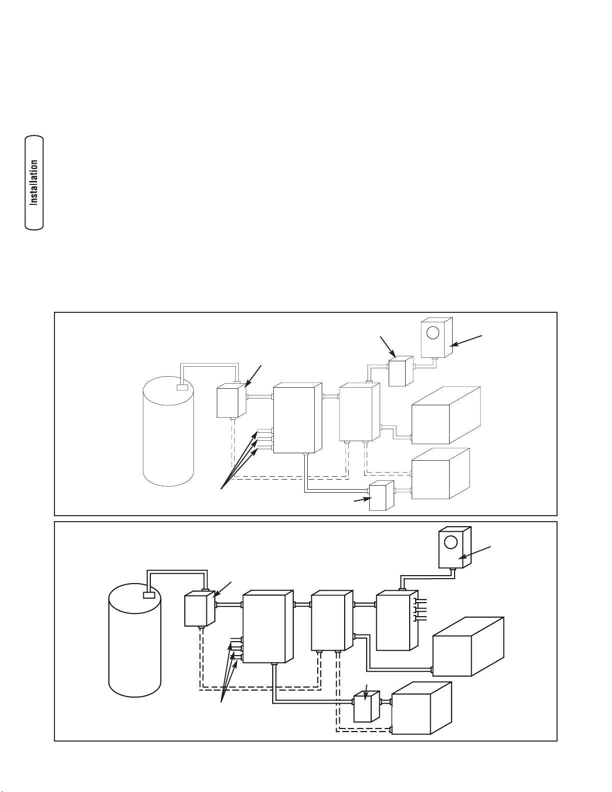
A typical installation of the Automatic Power Transfer Switch
is depicted below. An alternative installation of the Automatic
Power Transfer Switch is also depicted below. It is best if the
transfer switch is mounted near the utility meter, either
inside or outside. Discuss layout suggestions/ changes with
the owner before beginning the system installation process.
Main
Breaker
Panel
Transfer
Switch
Hot
Water
Heater
Air
Conditioner
Contactor
Service Disconnect
Generator
Watt -
Hourmeter
Branch Circuits
— — — — — — Control Wiring
Disconnect Switch
Typical
Main
Breaker
Panel
Transfer
Switch
Hot Water
Heater
Air
Conditioner
Contactor
Disconnect Switch
Generator
Watt -
Hourmeter
Branch Circuits
— — — — — — Control Wiring
Emergency
Load Center
Alternate
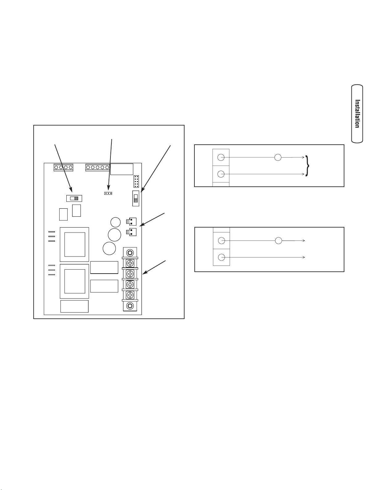
System Setup
You must perform the following on the control module
before operating the system:
• If generator is installed in an area regularly subjected to
temperatures below 40°F (4°C), select a 50 second
warm up time by moving jumper installed on JP2 from
‘20’ position to ‘50’ position.
• Place 2 position switch in ‘NG’ or ‘LP’ position,
whichever is appropriate for your system.
• Place 3 position switch to match KW rating of installed
generator.
Supervisory Control Wiring
1. Terminal strip on control module in transfer switch has
four connections for customer use. There are two sets
of “Normally Closed” contacts available. They will be
activated when generator power is required. These can
be used for supervisory control of large connected
loads on generator. Loads will be allowed to operate if
there is enough generator power available.
NOTE: There are two wireways provided to keep the
supervisory loads separated from each other.
2. Terminals “A-A” on control module are rated for 24 VAC
and air conditioner contactor control. Contacts are
connected in series with the air conditioner contactor
control circuit.
3. Terminals “B-B” on control module are rated for 1 Amp
125 VAC and installer supplied contactor to control a
large load. Example: electric hot water heater. Contacts
are connected in series with the contactor control
circuit.
4. Tighten all wire connections/fasteners to proper torque.
See inside transfer switch enclosure for proper torque
values.
7
A
A
Air Conditioner Contactor
24 VAC
B
B
Contactor
Neutral
(if applicable)
115 VAC
2 Position
Switch
3 Position
Switch
JP2
CT1 & CT2
Connectors
Supervisory
Contacts
8 BRIGGSandSTRATTON.COM
Wiring Interconnections
All wiring must be the proper size, properly supported and
protected by conduit.
Complete the following connections between the transfer
switch, main distribution panel, utility power and generator,
as shown on the next page.
High Voltage Wiring
1. Ensure utility power is turned OFF. Connect utility
Service conductors to line side of transfer switch
service disconnect circuit breaker.
2. Connect utility service Neutral conductor to the transfer
switch “NEUTRAL” terminal, if applicable.
3. Connect main breaker panel feeder conductors to
transfer switch terminals marked “LOAD
CONNECTION”.
4. Connect main breaker panel Neutral conductor to
transfer switch “NEUTRAL” terminal, if applicable.
5. Connect main breaker panel Ground conductor to the
transfer switch “GND” terminal.
NOTE: Assure grounding electrode conductor is connected
and bonded per applicable federal, state and local codes,
standards and regulations.
6. Connect generator feeder conductors from the
generator control panel to line side of transfer switch
“GENERATOR” breaker. Each conductor should pass
through hole of current transformer before making
connection.
7. Plug in current transformer leads into “CT1” and “CT2”
on control module.
8. Connect Neutral conductor from the generator control
panel to the transfer switch “NEUTRAL” terminal, if
applicable.
9. Connect generator Ground conductor from the control
panel to the transfer switch “GND” terminal.
NOTE: Assure generator equipment grounding conductor is
connected per applicable federal, state and local codes,
standards and regulations.
10. Connect generator “UTILITY 240 VAC” terminals to
transfer switch “UTILITY 240 VAC” terminals. Use
minimum #14 AWG conductors.
11. Tighten all wire connections/fasteners to proper torque.
See inside transfer switch enclosure for proper torque
values.
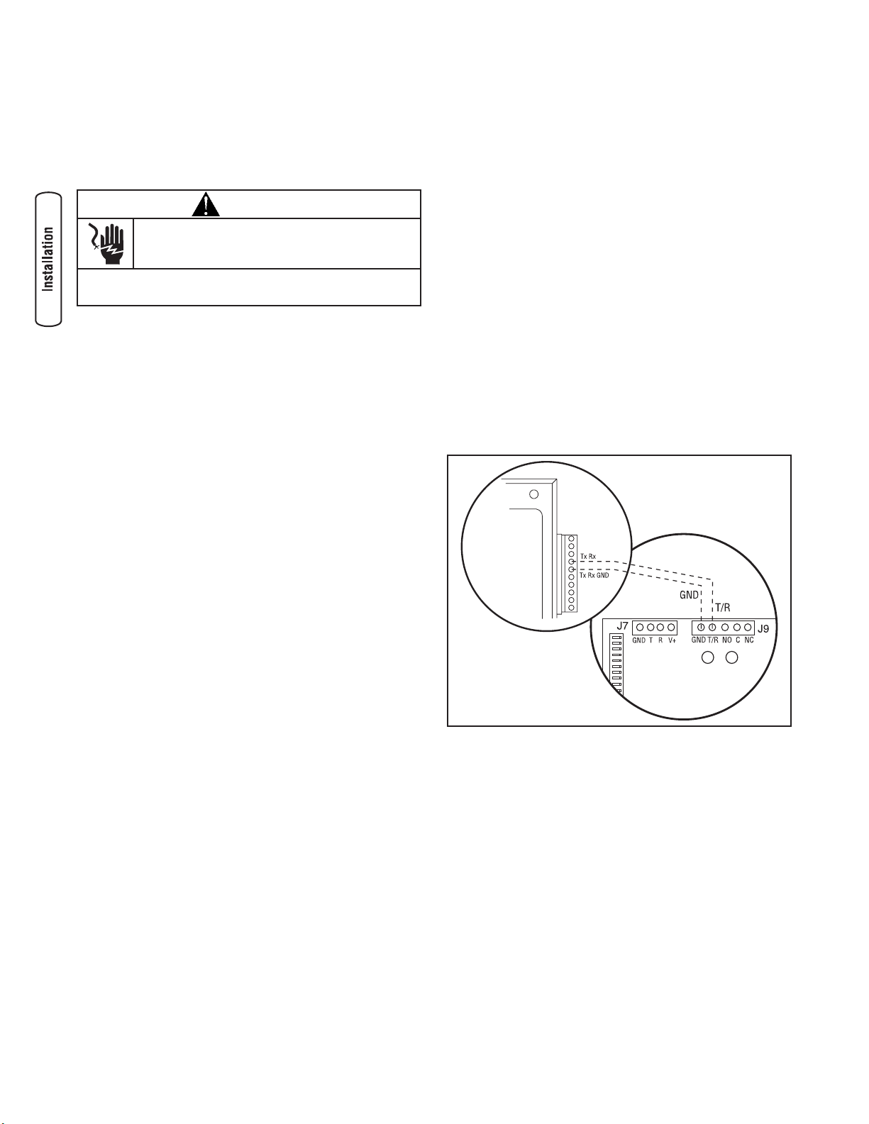
Low Voltage Wiring
1. Connect Tx Rx and Tx Rx Ground from the generator
control panel to the GND and T/R on the transfer switch
control board.
2. Tighten all wire connections/fasteners to proper torque.
See inside transfer switch enclosure for proper torque
values.
WARNING
Low voltage wire cannot be installed in same
conduit as power voltage wiring.
• Failure to follow above warning could cause personal injury,
damage and/or malfunction of equipment.
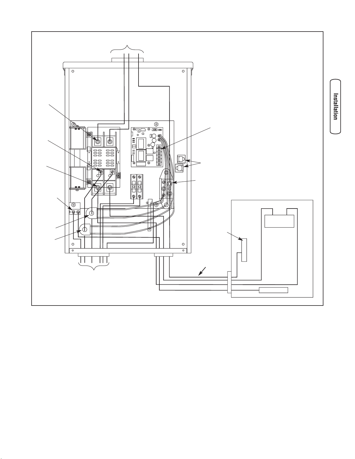
9
Main
Main Distribution Panel
Ground Bus
Neutral
Bus
To Generator
Neutral
Terminal
To Utility Power
Supervisory
Contacts
Load
Connection
Ground
Terminal
Generator
Connection
Utility
Connection
Wireways
CT 1
CT 2
If applicable
10 BRIGGSandSTRATTON.COM
Controls
Other than a Manual Override lever, there are no operator
controls because this is an automatic transfer switch. The
manual override is to be used only by licensed professionals.
Operation
To select automatic transfer operation, do the following:
1. Set service disconnect switch that sends utility power
to transfer switch contactor to “On” position.
2. Set generator’s main circuit breaker to its “On” position.
3. Install 15 Amp fuse in control panel on generator.
4A. If generator is equipped with a system AUTO/OFF
switch, set switch to “AUTO” position.
B. If generator is equipped with a AUTO/OFF/MANUAL
switch, set switch to “AUTO” position.
The system will now be in automatic operation mode.
When the generator is providing power to the transfer
switch, the controller is constantly monitoring generator
power. If the air conditioner is called to run, and there is
sufficient generator power available, the controller will close
contacts “A-A” to air conditioner contactor. Contacts “B-B”
will open before contacts A-A close. If loads are too great for
generator, contacts A-A and/or B-B will open. When air
conditioning is not needed, A-A will open. If enough power is
available, B-B will close.
Testing the Automatic Transfer Switch
Turn the service disconnect feeding the transfer switch
contactor to the “Off” position. The automatic sequence of
the system will follow. To go back to utility power, turn the
service disconnect to the “On” position.
Utility Fail
The Home Standby Generator set senses when utility voltage
is below 70 percent of nominal. Engine start sequence is
initiated after 6 second time delay.
Engine Warm-Up
Time delay to allow for engine warm-up before transfer is
fixed at 20 seconds or 50 seconds with removal of jumper
on control board.
Transfer
Transfer from utility to generator supply occurs after voltage
is above set levels. Minimum engine run time is 5 minutes
after transfer.
Utility Pickup
Voltage pickup level is 80 percent of nominal voltage.
Retransfer
Retransfer from generator to utility supply is approximately
10 seconds after utility voltage supply is above pickup level
and minimum run time is completed.
Engine Cool Down
Engine will run for 60 seconds after retransfer.
Maintenance
The transfer switch is designed to be maintenance free under
normal usage. However, inspection and maintenance checks
should be made on a regular basis. Maintenance will consist
mainly of keeping the transfer switch clean.
Visual inspections should be done at least once a month.
Access to transfer switch must not be obstructed. Keep
3 feet (92 cm) clearance around transfer switch. Check for
an accumulation of dirt, moisture and/or corrosion on and
around the enclosure, loose parts/hardware, cracks and/or
discoloration to insulation, and damaged or discolored
components.
Exercise the transfer switch at least once every three months
as described in the previous section Testing the Automatic
Transfer Switch unless a power outage occurs and Home
Generator System has gone through automatic sequence.
Allow generator to run for at least 30 minutes.
Contact a licensed electrical professional to inspect and clean
the inside of your transfer switch at least once a year.
Specifications
Maximum Load Current: . . . . . . . . . . . . . . . . . . . .100 Amps
Rated AC Voltage . . . . . . . . . . . . . . . . . . . . . . . . . .250 Volts
Poles . . . . . . . . . . . . . . . . . . . . . . . . . . . . . . . . . . . . . . . . . .2
Frequency . . . . . . . . . . . . . . . . . . . . . . . . . . . . . . . .50/60 Hz
Fault Current Rating . . . .25,000 RMS Symmetrical Amperes
Supervisory Contacts Rating:
A-A Terminals . . . . . . . . . . . . . . . . . . . . . . . . . .24 Volt AC
B-B Terminals . . . . . . . . . .1 Amp, 125 Volt AC, Pilot Duty
Weight . . . . . . . . . . . . . . . . . . . . . . . . . . . . . . . . . . . .21 lbs.
11
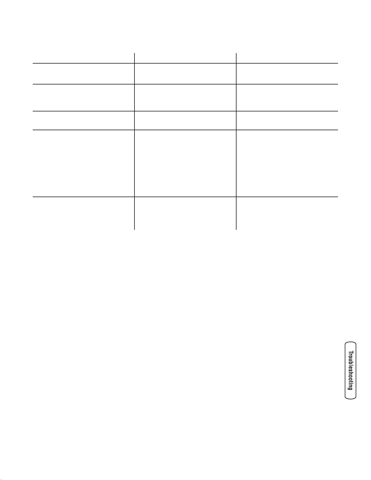
Troubleshooting
Problem Cause Correction
Automatic transfer switch does not
transfer to generator
1. Generator breaker open.
2. Generator voltage not acceptable.
1. Reset generator circuit breaker.
2. Refer to generator manual.
Automatic transfer switch does not
transfer to utility
1. Service disconnect breaker open.
2. Utility voltage not acceptable.
1. Reset service disconnect breaker.
2. Wait for utility voltage to return to
normal.
Generator is still running after switch
transfers to utility power
Engine cool down period. Engine should stop after 1 minute.
Generator or supervised loads (air
conditioner, etc.) are operating
improperly when generator is supplying
power
1. A-A or B-B contacts not operating
correctly.
2. Too much load on generator.
3. Current transformer not connected.
4. Broken current transformer.
1. Check A-A or B-B contacts for
proper operation and/or check
control wiring to external load.
2. Decrease load to generator.
3. Plug CT connectors into control
module.
4. Contact local Briggs & Stratton
service center.
Generator is still running after utility
power is restored
1. Minimum engine run time has not
elapsed.
2. Fuse(s) in transfer switch is
defective.
1. Wait five minutes for transfer
switch to retransfer to utility power.
2. Check fuse(s) and replace if
necessary.
12 BRIGGSandSTRATTON.COM
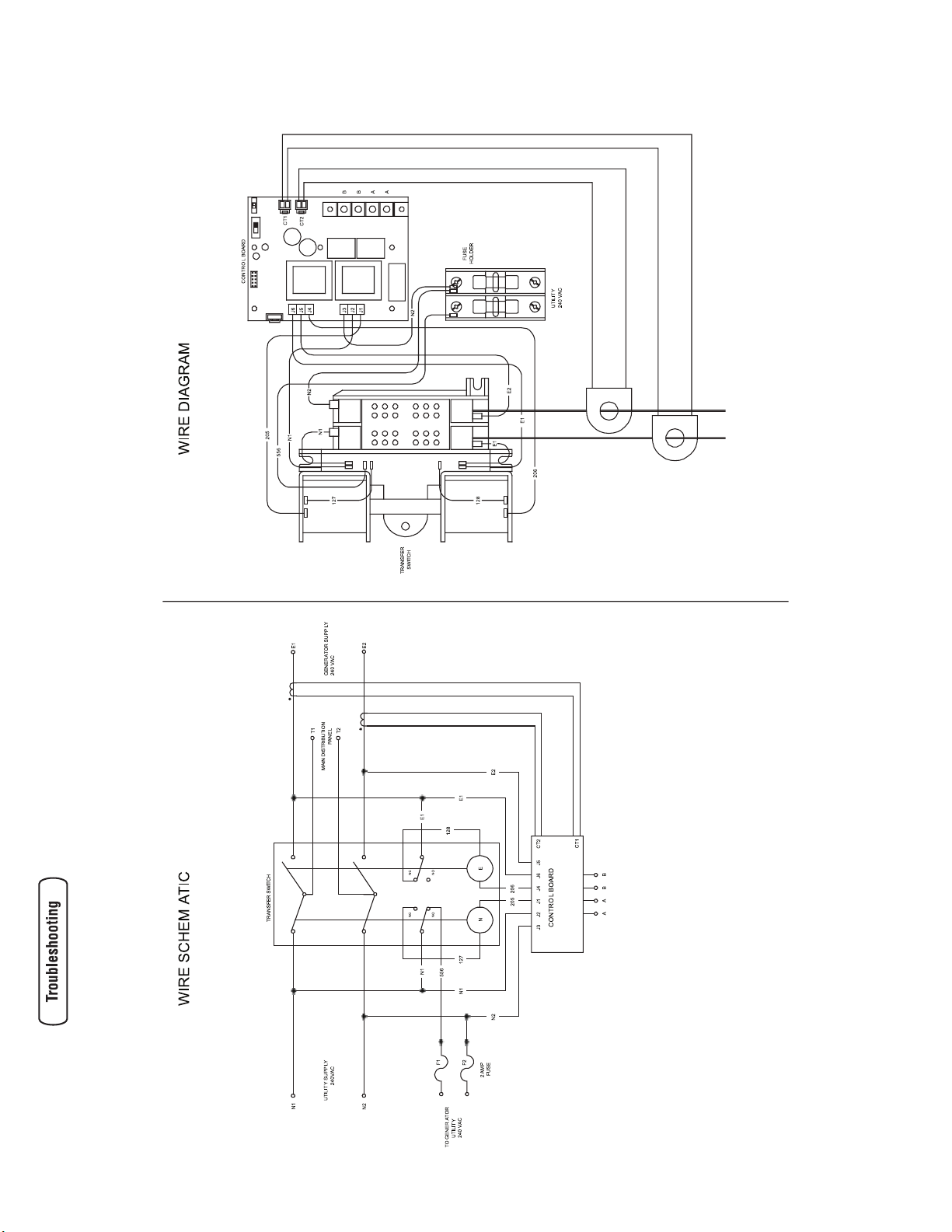
Transfer Switch Schematic and Wiring Diagram
 Loading...