

Briggs & Stratton 71013 User Manual 2
Installation &
Operator’s Manual
Guide d'Installation
et d'Utilisation
Manual de Instalación
y del Operario
Questions? Help is just a moment away!
Preguntas? La ayuda es justa
un momento lejos!
Vous avez des questions? Vous n'avez pas
besoin d'aller loin pour trouver de l'aide!
Call: Helpline
Llamada: Línea Directa
Appelez: Ligne Directe
1-800-743-4115 M-F 8-5 CT
Web: www.briggsandstratton.com
Model 071013 Part No. 198113GS
Rev.B (02/06/2007)

2
TABLE OF CONTENTS
TABLE OF CONTENTS
TABLE OF CONTENTS . . . . . . . . . . . . . . . . . . . . . . . . . . . 2
IMPORTANT SAFETY INSTRUCTIONS . . . . . . . . . . . . . . 3
INTRODUCTION. . . . . . . . . . . . . . . . . . . . . . . . . . . . . . . . 4
For the Home Owner: . . . . . . . . . . . . . . . . . . . . . . . . 4
For the Installing Dealer/Contractor: . . . . . . . . . . . . . 4
Owner Orientation . . . . . . . . . . . . . . . . . . . . . . . . . . . 5
Installer Responsibilities . . . . . . . . . . . . . . . . . . . . . . . . 5
Equipment Description. . . . . . . . . . . . . . . . . . . . . . . . . 5
INSTALLATION. . . . . . . . . . . . . . . . . . . . . . . . . . . . . . . . . . 6
Unpacking . . . . . . . . . . . . . . . . . . . . . . . . . . . . . . . . . . . 6
Delivery Inspection . . . . . . . . . . . . . . . . . . . . . . . . 6
Shipment Contents . . . . . . . . . . . . . . . . . . . . . . . . 6
Mounting Guidelines. . . . . . . . . . . . . . . . . . . . . . . . . . . 6
Power Wiring Interconnections . . . . . . . . . . . . . . . . 7-8
System Setup . . . . . . . . . . . . . . . . . . . . . . . . . . . . . . . . 8
Wiring Decal. . . . . . . . . . . . . . . . . . . . . . . . . . . . . . . . . 9
SPECIFICATIONS . . . . . . . . . . . . . . . . . . . . . . . . . . . . . . . 10
SYSTEM OPERATION. . . . . . . . . . . . . . . . . . . . . . . . . . . . 10
TESTING THE POWER MANAGEMENT SYSTEM . . . . 10
When Calling The Factory . . . . . . . . . . . . . . . . . . . . . 10
TROUBLESHOOTING . . . . . . . . . . . . . . . . . . . . . . . . . . . 11
WORKSHEET . . . . . . . . . . . . . . . . . . . . . . . . . . . . . . . . . . 12
EXPLODED VIEW & PARTS LIST. . . . . . . . . . . . . . . . . . . 13
NOTES . . . . . . . . . . . . . . . . . . . . . . . . . . . . . . . . . . . . . . . 14
WARRANTY . . . . . . . . . . . . . . . . . . . . . . . . . . . . . . . . . . . 15
Copyright © 2006 Briggs & Stratton Power Products Group, LLC. All rights reserved. No part of this material may be
reproduced or transmitted in any form by any means without the express written permission of Briggs & Stratton Power
Products Group, LLC.
3
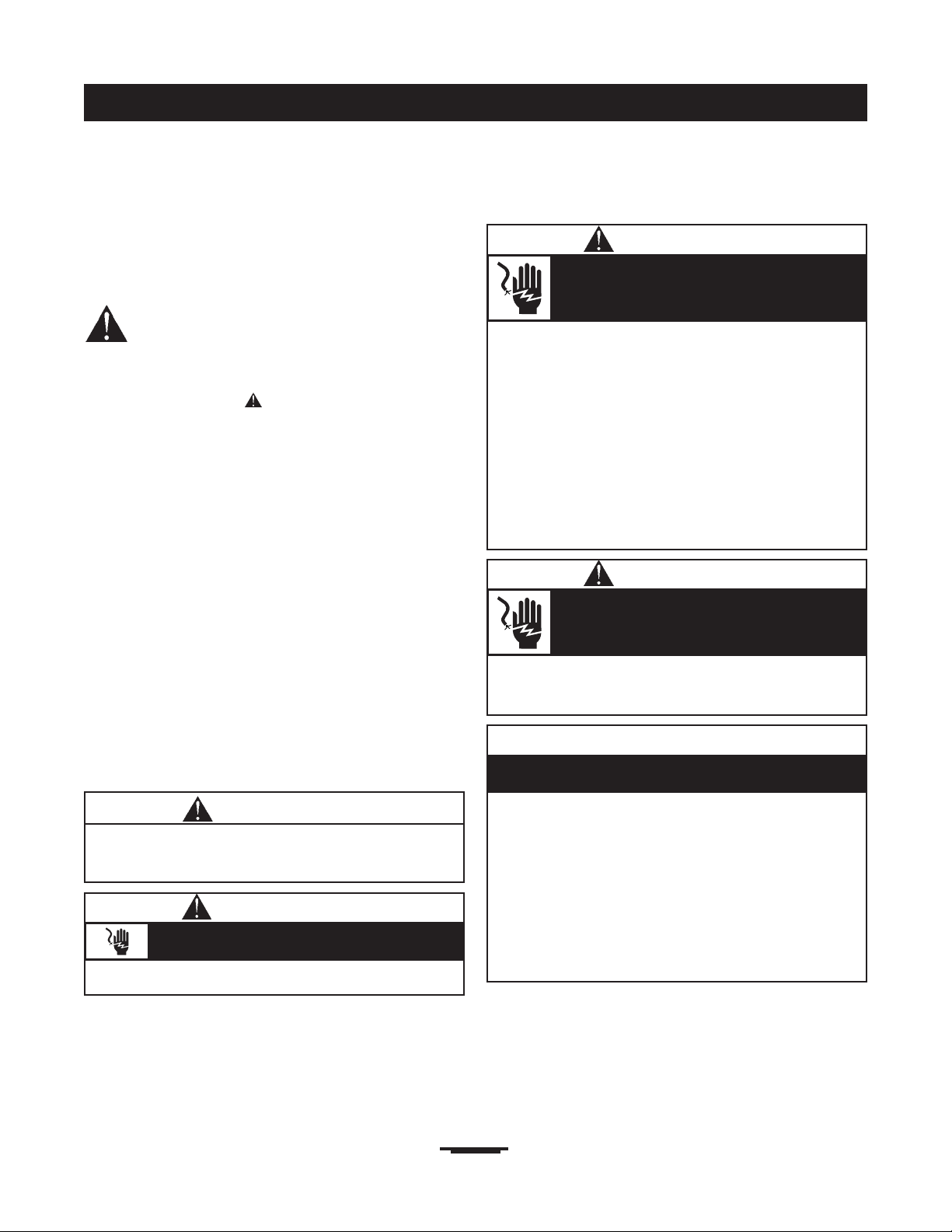
IMPORTANT SAFETY
INSTRUCTIONS
This is the safety alert symbol. It is used to
alert you to potential personal injury
hazards. Obey all safety messages that follow
this symbol to avoid possible injury or death.
The safety alert symbol ( ) is used with a signal word
(DANGER, CAUTION,WARNING), a pictorial and/or a
safety message to alert you to hazards. DANGER indicates
a hazard which, if not avoided, will result in death or
serious injury. WARNING indicates a hazard which, if not
avoided, could result in death or serious injury.
CAUTION indicates a hazard which, if not avoided, might
result in minor or moderate injury. CAUTION, when
used without the alert symbol, indicates a situation that
could result in equipment damage. Follow safety messages
to avoid or reduce the risk of injury or death.
The manufacturer cannot possibly anticipate every possible
circumstance that might involve a hazard.The warnings in
this manual, and the tags and decals affixed to the unit are,
therefore, not all-inclusive. If you use a procedure, work
method or operating technique that the manufacturer does
not specifically recommend, you must satisfy yourself that it
is safe for you and others.You must also make sure that the
procedure, work method or operating technique that you
choose does not render the power management system
unsafe.
• DO NOT touch bare wires.
• DO NOT use power management system with worn, frayed,
bare or otherwise damaged wiring.
• DO NOT handle electrical cords while standing in water,
while barefoot, or while hands or feet are wet.
• If you must work around a unit while it is operating, stand on
an insulated dry surface to reduce shock hazard.
• DO NOT allow unqualified persons or children to operate or
service power management system.
• In case of an accident caused by electrical shock, immediately
shut down all sources of electrical power and contact local
authorities. Avoid direct contact with the victim.
Failure to properly ground power management
system can result in electrocution.
WARNING
Only qualified electricians should attempt installation
of this system, which must strictly comply with
applicable codes, standards and regulations.
WARNING
• Use power management system only for intended uses.
• If you have questions about intended use, ask dealer or
contact Briggs and Stratton Power Products.
• DO NOT expose power management system to excessive
moisture, dust, dirt, or corrosive vapors.
• Remain alert at all times while working on this equipment.
NEVER work on the equipment when you are physically or
mentally fatigued.
• If connected devices overheat,turn them off and turn off their
circuit breaker/fuse.
Improper treatment of power management system can
damage it and shorten its life.
CAUTION
SAFETY INSTRUCTIONS
SAVE THESE INSTRUCTIONS
• Despite the safe design of the power management system,
operating this equipment imprudently, neglecting its maintenance
or being careless can cause possible injury or death.
Power management system contains high
voltage that can cause personal injury or death.
WARNING
• Failure to follow above warning could cause personal injury,
damage and/or malfunction of equipment.
Low voltage wire cannot be installed in same
conduit as power voltage wiring.
WARNING

4
INTRODUCTION
INTRODUCTION
Thank you for your purchase of this Briggs & Stratton
Power Management System.This product is intended for
use with Briggs & Stratton Automatic Transfer Switches and
Home Standby Generators ONLY.This is an optional
automated system that will control the distribution of
power from a home standby system (generator) to selected
household loads.
Briggs and Stratton (B&S) has made every effort to provide
for a safe, streamlined and cost-effective installation.As
each installation is unique, it is impossible to know of and
advise of all conceivable procedures and methods by which
installation might be achieved.We do not know all possible
hazards and/or the results of each method or procedure.
For these reasons,
Only licensed electrical contractors
should install power management
systems. Installations must strictly comply
with all applicable federal, state and local
codes, standards and regulations.
Your B&S power management system is supplied with this
combined “Installation and Operator’s Manual”.This is an
important document and should be retained by the owner
after the installation has been completed.
Every effort has been expended to make sure that the
information in this manual is both accurate and current.
However, the manufacturer reserves the right to change,
alter or otherwise improve the system at any time without
prior notice.
For the Home Owner
To help you make informed choices and communicate
effectively with your installation contractor(s),
Read and understand the
Owner Orientation Section of this manual
BEFORE
contracting or starting
your power management system installation.
To arrange for proper installation, contact the store at
which you purchased your B&S power management system,
your dealer, or your utility power provider.
The power management system
warranty is V
OID unless the system is installed
by a licensed electrical professional.
For the Installing Dealer/Contractor
Check federal, state and local codes for questions on
installation.
If you need more information about the power
management system, call 1-800-743-4115, between
8:00 AM and 5:00 PM CT.

5
INTRODUCTION
Owner Orientation
The illustrations are for typical circumstances and are
meant to familiarize you with the installation options
available with your power management system.
Local codes, appearance, and distances are the factors that
must be considered when negotiating with an installation
professional.As the distance from the existing electrical
service increases, compensation in wiring materials must be
allowed for.This is necessary to comply with local codes
and overcome electrical voltage drops.
The factors mentioned above will have a direct
effect on the overall price of your power
management system installation.
NOTE:Your installer must check local codes AND obtain
permits before installing the system.
• Read and follow the instructions given in this manual.
• Follow a regular schedule in caring for and using your
power management system, as specified in the manual.
Installer Responsibilities
• Read and observe the safety rules.
• Read and follow the instructions given in this manual.
• Check federal, state and local codes.
• Consult with owner to determine loads to be controlled
and their priorities.
NOTE:A worksheet for determining which loads are to
be transferred and their priorities is provided on page 12.
• May need to provide appropriate rated contactors based
on loads to be controlled.
Equipment Description
The power management system is designed to control
six priority loads and up to two air conditioner loads that
are being supplied by power from the home standby
system.This power management system goes into a
STANDBY mode and does not control any loads when
utility power is present.
The power management system consists of a relay board
with 6 relays to control loads rated up to 120 VAC,
20 Amps, 1 hp, and a control module that has 2 relays for
central air conditioner loads.The circuit boards are housed
in a NEMA 3R enclosure that is suitable for both indoor
and outdoor installations.
Two (2) current transformers monitor generator current at
the transfer switch to ensure that the loading of the
generator does not exceed 85 percent. Should load exceed
85 percent, the power management system will start to
shed loads to keep the generator from overloading.The
power management system will add load back once
sufficient current is available.
The controle module has a green LED for each relay to
indicate when the relays are supplying power to the loads
when on generator power.There is also a status LED that
flashes when the power management system is functioning
properly.
6
INSTALLATION
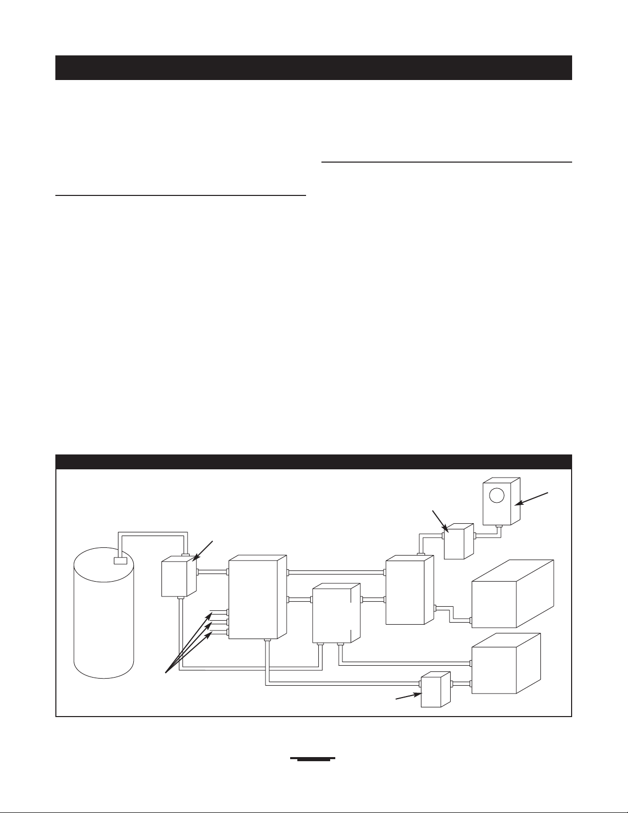
Figure 1 — A Typical Power Management System Mounting
Main
Breaker
Panel
Transfer
Switch
Hot
Water
Heater
Air
Conditioner
Contactor
Service Disconnect
Generator
Watt -
Hourmeter
Branch Circuits
INSTALLATION
Unpacking
Delivery Inspection
After removing the carton, carefully inspect the power
management system components for any damage that may
have occurred during shipment.
IMPORTANT: If loss or damage is noted at time of
delivery, have the person(s) making delivery note all damage
on the freight bill and affix his signature under the
consignor's memo of loss or damage. If loss or damage is
noted after delivery, contact the carrier for claim
procedures. Missing or damaged parts are not warranted.
Shipment Contents
• Power Management System
• Installation and Operator’s Manual
• Wire Connectors (4)
• 1/4” Double Male, Single Female Lugs (2)
Mounting Guidelines
The power management system is enclosed in a NEMA
Type 3R enclosure suitable for indoor/outdoor use.
Guidelines for mounting the power management system
include:
• Install power management system on a firm, sturdy
supporting structure.
• The power management system must be installed with
minimum NEMA 3R hardware for conduit connections.
• Level and plumb the enclosure.This can be done by
placing washers between the power management system
enclosure and the mounting surface.
• NEVER install the power management system where any
corrosive substance might drip onto the enclosure.
• Protect the power management system at all times
against excessive moisture, dust, dirt, lint, construction
grit and corrosive vapors.
A typical installation of the power management system is
depicted in Figure 1. It is best if it is mounted near the main
breaker panel, either inside or outside. Discuss layout
suggestions/changes with the owner before beginning the
system installation process.
Disconnect Switch
Power
Management
System
7
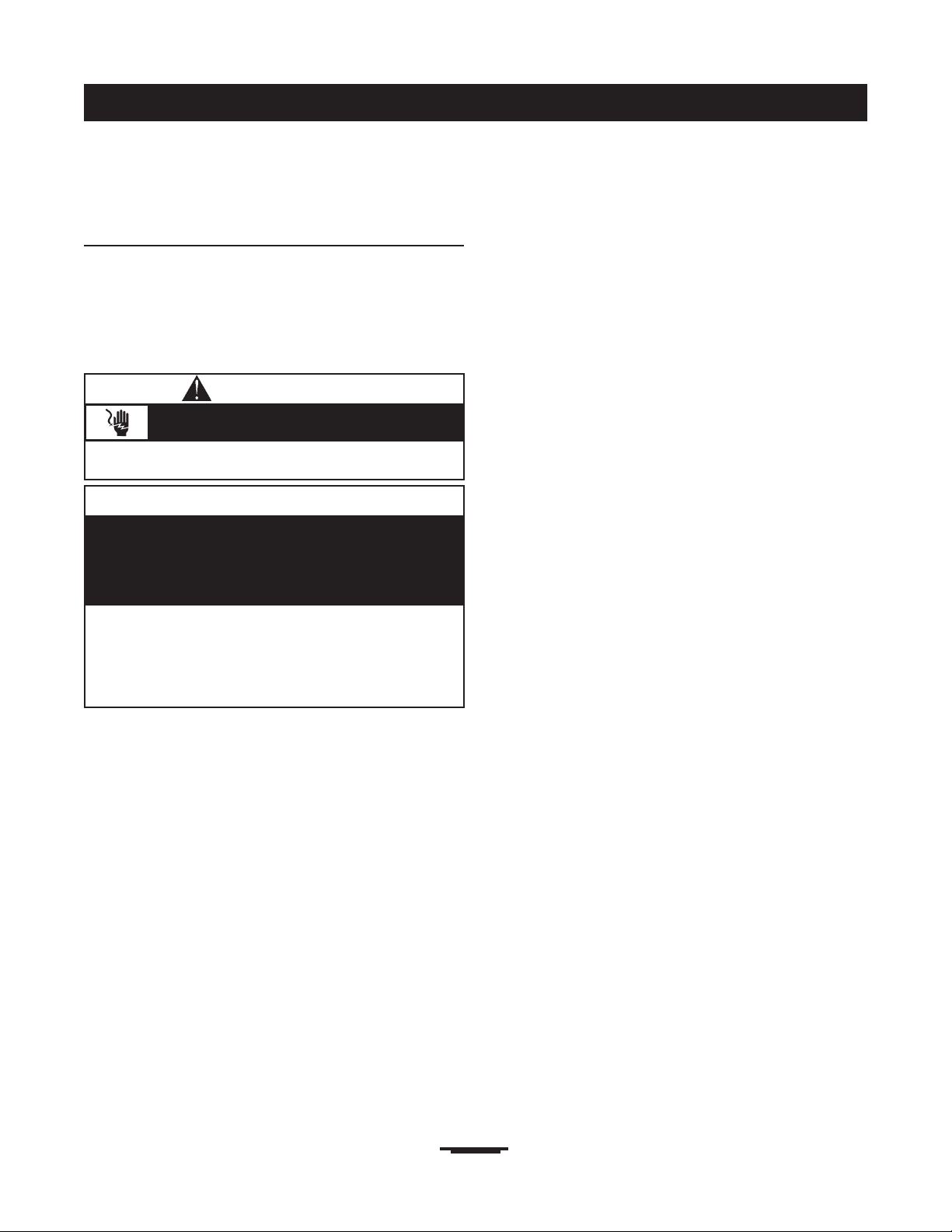
INSTALLATION
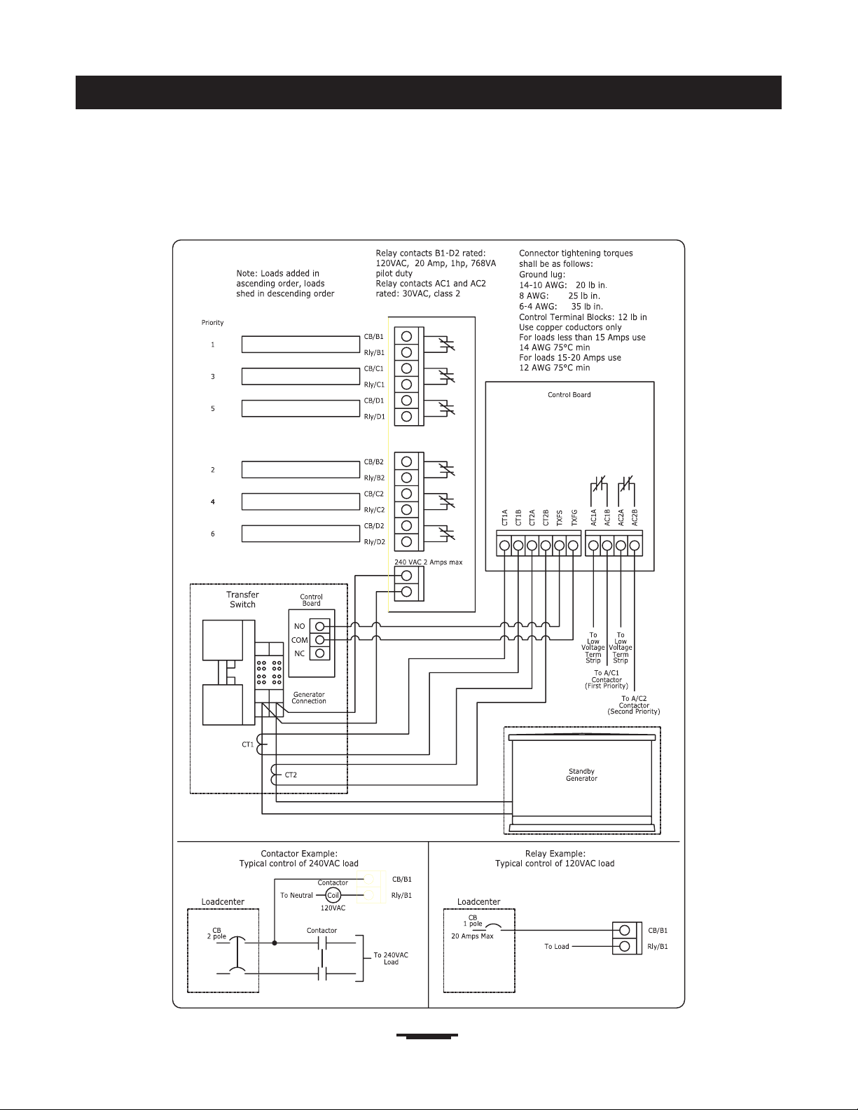
Power Wiring Interconnections
All wiring must be the proper size, properly supported and
protected by conduit.All wiring should be done per applicable
federal, state and local codes, standards and regulations.
Complete the following connections between the transfer
switch, power management system and main breaker panel
(Figure 2, on next page).Also see the wiring decal on page 9.
1. Set generator’s main circuit breaker to OFF (open)
position.
2. Identify loads and their priorities (using sheet
provided) to be transfered to power management
system in main breaker panel.
3. In main breaker panel, turn selected load circuit
breakers to OFF position.
4. Connect “GND” lug to an approved ground.
NOTE:Assure grounding electrode conductor is
connected and bonded per applicable federal, state and
local codes, standards and regulations.
5. Using supplied 1/4” double male, single female lugs,
connect generator 240VAC from transfer switch to
relay board in power management system.
6. Unplug current transformers from controle module in
transfer switch.
7. Cut two pin connector ends off of current transformer
leads and discard. Strip wires and place in supplied wire
connectors.
8. Using installer supplied 300VAC or greater wire, run
wires from wire connectors to controle module
terminal block labeled “CT1A” through “CT2B” in
power management system.
9. Using installer supplied 300VAC or greater wire,
connect controle module terminals “B-B” in transfer
switch to controle module terminal block labeled
“TXSF” and “TXFG” in power management system.
10. Wire the air conditioner thermostat control wiring to
the controle module labeled “AC1A-AC2B” in power
management system.
NOTE:AC1A and AC1B is for the priority 1 air
conditioner.AC2A and AC2B is for the priority 2 air
conditioner.
11. For 120VAC selected loads,remove wire from selected
load circuit breaker.
12. Using installer supplied 300VAC or greater wire,
connect selected load circuit breaker to terminal block
at power management system labeled “CB/B1” for
priority 1 load.
13. Using installer supplied 300VAC or greater wire and a
wire nut, connect the selected load wire to terminal
block in power management system labeled “RLY/B1”
for priority 1 load.
14. Repeat steps 11 through 13 for all other 120VAC
priorities using terminals “CB/C1” through “RLY/D2”.
15. For 240VAC selected loads,remove both wires from
selected load circuit breaker and place in load side of
installer supplied contactor.
16. Using installer supplied 300VAC or greater wire,
connect circuit breaker to line side of contactor.
17. Using installer supplied 300VAC or greater wire,
connect one pole of the circuit breaker to terminal
block in power management system labeled “CB/B1”
for a priority 1 load.
18. Using installer supplied 300VAC or greater wire,
connect Neutral in main breaker panel to contactor coil.
19. Using installer supplied 300VAC or greater wire, connect
contactor coil to terminal block in power management
system labeled “RLY/B1” for a priority 1 load.
20. Repeat steps 15 through 19 for all other 240VAC
priorities using terminals “CB/C1” through “RLY/D2”.
21. Tighten all wire connections/fasteners to proper
torque. See inside power management system
enclosure for proper torque values.
• Failure to follow above warning could cause personal injury,
damage and/or malfunction of equipment.
Low voltage wire cannot be installed in same
conduit as power voltage wiring.
WARNING
• Remove all power prior to installing this power management
system. Failure to do so could cause internal damage to the
board when making electrical connections.
• Turn generator to OFF position.
• Turn off utility power to the home standby generator and
transfer switch.
Improper installation can cause damage to the circuit
boards and shorten their life. Installing circuit boards in live
circuits will damage the board and is not a warranty
condition.ALWAYS disconnect ALL sources of power prior
to servicing.
CAUTION
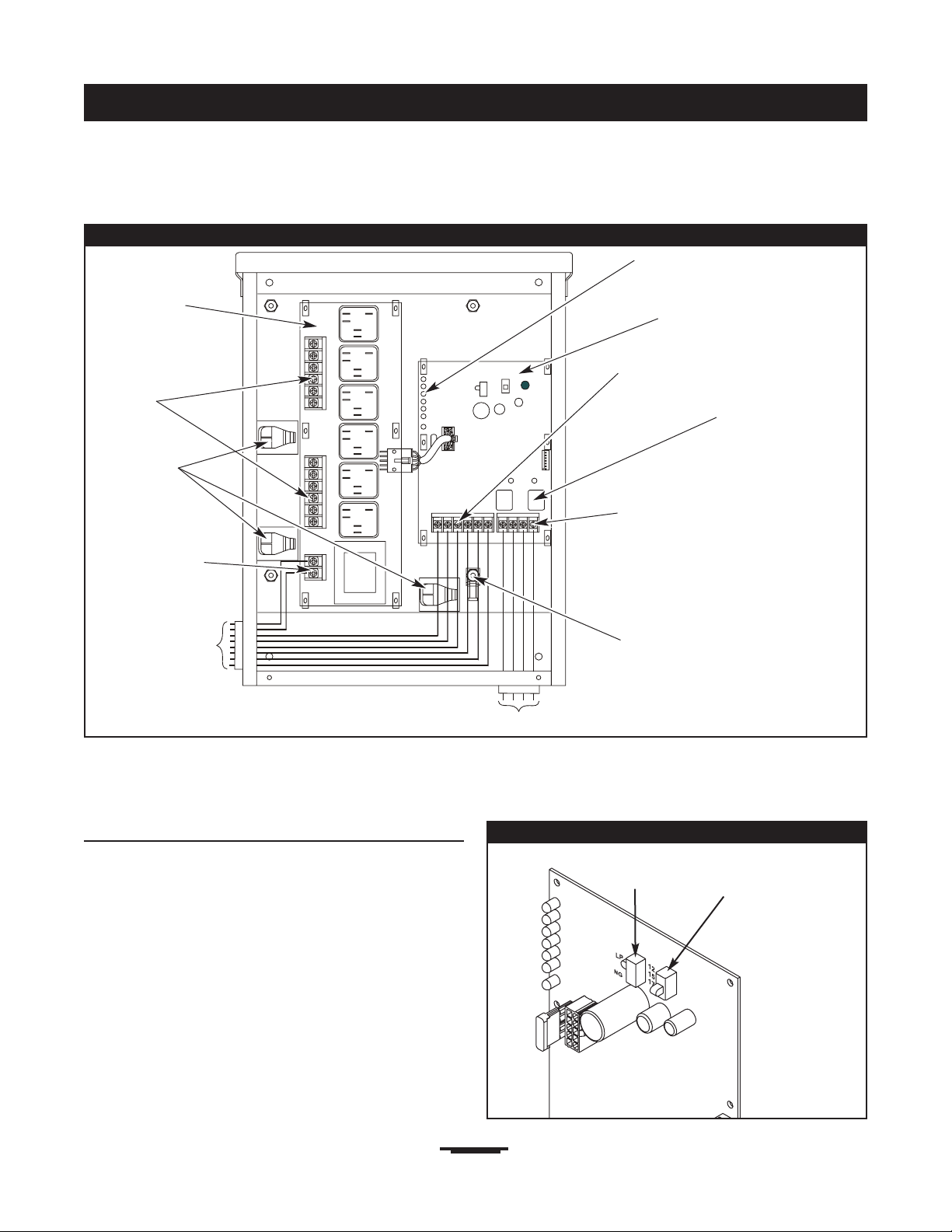
Figure 2 — A Typical Installation Diagram for Power Management System
Ground Lug
To Transfer Switch
Air Conditioner
Relays
Load
Connection
Controle
Module
Generator
Connection
Air Conditioner
Connections
8
INSTALLATION
Wireways
System Setup
You must perform the following before operating the system:
• Place the 2 position sliding switch on the control module
in the NG or LP position (Figure 3), whichever is
appropriate for the installed home standby system.
• Place the 3 position sliding switch on the control module
to match the rating of the home standby system (Figure 3).
• In main breaker panel, turn selected load circuit breakers
to the ON position.
IMPORTANT:After installation of the power
management system is complete, turn on utility power to
the home standby generator and transfer switch.Wait one
minute before turning generator to AUTO.
Figure 3 — Control Module
2 Position
Switch
3 Position
Switch
Relay Board
To Air Conditioners
Transfer Switch
Connections
Green LED’s
9
INSTALLATION
WIRING DECAL

10
SPECIFICATIONS AND OPERATION
SPECIFICATIONS
Rated AC Voltage. . . . . . . . . . . . . 125/250 Volts
Frequency . . . . . . . . . . . . . . . . . . 50/60 Hz
Relay Contacts Rating . . . . . . . . . 125 VAC, 20A, 1 HP, 768 VA
Pilot Duty
Weight . . . . . . . . . . . . . . . . . . . . . 34 lbs.
SYSTEM OPERATION
When the home standby system is providing power to the
transfer switch, the power management system is
constantly monitoring generator power to control loads.
The power management system monitors both incoming
generator lines and keeps the home standby system loaded
to a maximum of 85-86 percent of rated load.When the
current transformers on any line start to see current reach
85-86 percent of rated load, the power management
system will start shedding loads based on the lowest
priority and work its way to the highest priority.When
current has dropped below 85-86 percent of rated load,
the power management system will start to add loads
based on the highest priority first, followed by the second
highest until the generator reaches 85-86 percent load or
all priorities are back on line.The power management
system will operate this way until the transfer switch
transfers back to utility position.
The power management system waits 5 seconds between
adding or shedding each load to permit the system to
stabilize.When a relay is opened, the relay will stay opened
for a minimum of 5 minutes or until the load can be added
without putting the generator over 85-86 percent of rated
load. If a large load demand is seen, the power management
system will shed loads at a quicker rate of less than
1.5 seconds to prevent the generator from overloading.
Once the demand has stabilized and the loads can be added
again, the power management system will start with the
highest priority, wait 5 seconds and then add the next
priority.The unit will continue to do this until all loads are
added or 85-86 percent of rated load is reached.
When the generator is powering loads, the A/C relays are
open.When one or both of the relays sense 24VAC from
the thermostat(s), the controller will shed loads B1-D2, and
then will allow only one A/C relay to close.A1 has priority
over A2. A2 can close when the signal for A1 has expired.
When the A/C’s are being called to run, all loads are to be
shed before the A/C unit can be added. Should A/C 1 call
while A/C 2 is running,A/C 2 shall open, all relays would
open and then A/C 1 can close.When the A/C relays open,
they are to be locked out for a minimum of 5 minutes or
until they receive a call to start the A/C.
TESTING THE POWER
MANAGEMENT SYSTEM
With the generator in “Auto“ position, turn the service
disconnect feeding the transfer switch contactor to the
“Off” position.The generator will start and the transfer
switch will transfer to generator power.
Press the test button on the controle module of the power
management system.As the button is pressed, a relay will
energize. Each time the button is pressed, the previous relay
that was energized, will de-energize and the next relay will
energize.
Press the test button once and relay B2 will energize. Press
the test button again and B2 will de-energize and relay C1
will energize.This will proceed until all relays have been
tested or if the test button has not been pressed for a
period of 30 seconds, the test sequence will halt and the
system will go back to automatic control.
To go back to utility power, turn the service disconnect
feeding the transfer switch contactor to the “On” position.
When Calling the Factory
Before contacting Briggs & Stratton regarding service or
repair of this power management system, obtain the Model
Number and Serial Number from the unit data decal
located on or inside the enclosure.
To contact Briggs & Stratton call 1-800-743-4115, between
8:00 AM and 5:00 PM CT.

11
TROUBLESHOOTING
TROUBLESHOOTING
Problem Cause Correction
Supervised loads (air conditioner,
etc.) are not operating when
generator is supplying power
1. AC1A-AC2B contacts not
operating correctly.
2. Too much load on generator.
3. Current transformer not
connected.
4. Broken current transformer.
5. Status LED stays lit constantly.
1A. Check AC1A-AC2B contacts for
proper operation.
B. Check control wiring to external
load.
C. Check harness between boards is
properly connected.
D. Check that there is 24 VAC to one
of the terminals.
E. Be sure 5 minute lock out has
elapsed.
F. Be sure air conditioner start time
delay has elapsed.
2. Decrease load to generator.
3. Connect current transformer.
4. Replace current transformer.
5. Contact an authorized service
center.

12
WORKSHEET
Priority 120VAC Electrical Appliances Priority 240VAC Electrical Appliances
Window Air Conditioner 1 Central Air Conditioner 1
Window Air Conditioner 2 Central Air Conditioner 2
Window Air Conditioner 3 Range/Stove
Refrigerator 1 Dryer
Refrigerator 2 Well Pump
Freezer 1 Hot Tub
Freezer 2 Pool Heater
Microwave Water Heater
Bathroom Other:________________________
Auxiliary Heater Other:________________________
Home Theater System Other:________________________
Garage Heater
Sink Water Heater
Sewage Lift Pump
Other:________________________
Other:________________________
Other:________________________
IMPORTANT: DO NOT connect furnace and sump pump to power management system.
ELECTRICAL LOAD WORKSHEET
 Loading...