

Briggs & Stratton 700 DOV Series, 750 DOV Series Repair Manual

700/750 SERIES DOV AIR-COOLED ENGINES
273521 Twin Cylinder OHV Air-Cooled Engines
276781 Single Cylinder OHV Air-Cooled Engines
271172 Twin Cylinder L-Head Air-Cooled Engines
270962 Single Cylinder L-Head Air-Cooled Engines
276535 Two-Cycle Snow Engines
CE8069 Out of Production Engines (1919-1981)
Repair Manuals for other
Briggs & Stratton Engines:
700/750 Series DOV
Air-Cooled Engines
POST OFFICE BOX 702
MILWAUKEE, WI 53201 USA
©2009 Briggs & Stratton Corporation
BRIGGS&STRATTON
CORPORATION
Part No. 277527-12/09
Quality Starts With A
Master Service Technician
www.ThePowerPortal.com (Dealers)
BRIGGSandSTRATTON.COM (Consumers)
Briggs & Stratton
12/09


FORWARD
This manual was written to assist engine technicians and service personnel with the repair and
maintenance procedures for Briggs & Stratton engines. It assumes that persons using this manual have
been properly trained in and are familiar with the servicing procedures for these products, including the
proper use of required tools and safety equipment and the application of appropriate safety practices.
Persons untrained or unfamiliar with these procedures or products should not attempt to perform such
work.
Proper maintenance and repair is important to safe, reliable operation of all engines and engine-driven
systems. The troubleshooting, testing, maintenance, and repair procedures described in this manual are
appropriate for the Briggs & Stratton engines described herein. Alternative methods or procedures may
pose risk to personal safety and the safety and/or reliability of the engine and are not endorsed or
recommended by Briggs & Stratton.
All information, illustrations, and specifications contained in this manual were based on the data available
at the time of publication. Briggs & Stratton Corporation reserves the right to change, alter, or otherwise
improve the product or the product manuals at any time without prior notice.
Briggs & Stratton offers two complementary publications to enhance understanding of engine technology,
maintenance, and repair. (Neither publication, however, is a substitution for a recognized training program
for engine technicians.)
• For consumers, Small Engine Care & Repair (p/n 274041) provides a comprehensive overview of how
small air-cooled engines work, basic troubleshooting, and step-by-step maintenance procedures.
• For engine technicians and consumers alike, an in-depth study of engine theory and operation can be
found in the textbook Small Engines (p/n CE8020).
Both publications can be purchased at BRIGGSandSTRATTON.COM or through a local Authorized Briggs
& Stratton Service Dealer.
Copyright © 2009 Briggs & Stratton Corporation
All rights reserved.
No part of this manual may be reproduced or transmitted in any form or by any means, electronic or
mechanical, including photocopying or recording by any information storage and retrieval system, without
prior written permission from Briggs & Stratton Corporation.

This engine repair manual includes the following
engine models:
• MODEL 090600
• MODEL 100600
• MODEL 100800
6

SECTION 1 - Safety, Maintenance and Adjustments
SECTION 2 - Troubleshooting
SECTION 3 - Exhaust Systems
SECTION 4 - Fuel Systems and Carburetion
SECTION 5 - Governor Systems
SECTION 6 - Cylinder Heads and Valves
SECTION 7 - Starters
1
2
3
4
5
6
7
SECTION 8 - Lubrication Systems
SECTION 9 - Cylinders, Covers and Sumps
SECTION 10 - Crankshafts, Camshafts, Balancing Systems, and Gear Reductions
SECTION 11 - Pistons, Rings and Connecting Rods
SECTION 12 - Engine Specifications
8
9
10
11
12

THISPROPER SERVICE AND REPAIR IS IMPORTANT
TO THE SAFE, ECONOMICAL AND RELIABLE

SECTION 1 - SAFETY, MAINTENANCE, AND ADJUSTMENTS
SAFETY INFORMATION - - - - - - - - - - - - - - - - - - - - - - - - - - - - - - - - - - - - - - - - - - - - - - - - - - - - - - - - 4
ENGINE MAINTENANCE - - - - - - - - - - - - - - - - - - - - - - - - - - - - - - - - - - - - - - - - - - - - - - - - - - - - - - - - 7
FUEL AND OIL RECOMMENDATIONS - - - - - - - - - - - - - - - - - - - - - - - - - - - - - - - - - - - - - - - - - - - - - - 7
MAINTENANCE CHART - - - - - - - - - - - - - - - - - - - - - - - - - - - - - - - - - - - - - - - - - - - - - - - - - - - - - - - - - 7
OIL CHANGE- - - - - - - - - - - - - - - - - - - - - - - - - - - - - - - - - - - - - - - - - - - - - - - - - - - - - - - - - - - - - - - - - 8
AIR FILTER - - - - - - - - - - - - - - - - - - - - - - - - - - - - - - - - - - - - - - - - - - - - - - - - - - - - - - - - - - - - - - - - - 8
SPARK PLUG - - - - - - - - - - - - - - - - - - - - - - - - - - - - - - - - - - - - - - - - - - - - - - - - - - - - - - - - - - - - - - - - 8
COOLING SYSTEM - - - - - - - - - - - - - - - - - - - - - - - - - - - - - - - - - - - - - - - - - - - - - - - - - - - - - - - - - - - - 9
CHARGING BATTERY - - - - - - - - - - - - - - - - - - - - - - - - - - - - - - - - - - - - - - - - - - - - - - - - - - - - - - - - - - 9
COMBUSTION CHAMBER - - - - - - - - - - - - - - - - - - - - - - - - - - - - - - - - - - - - - - - - - - - - - - - - - - - - - - -10
ENGINE ADJUSTMENTS - - - - - - - - - - - - - - - - - - - - - - - - - - - - - - - - - - - - - - - - - - - - - - - - - - - - - - - -10
THROTTLE CABLE ADJUSTMENT - - - - - - - - - - - - - - - - - - - - - - - - - - - - - - - - - - - - - - - - - - - - - - - - -10
GOVERNOR ADJUSTMENTS- - - - - - - - - - - - - - - - - - - - - - - - - - - - - - - - - - - - - - - - - - - - - - - - - - - - -10
ADJUST VALVE CLEARANCE - - - - - - - - - - - - - - - - - - - - - - - - - - - - - - - - - - - - - - - - - - - - - - - - - - - -12
ADJUST READYSTART CHOKE LINK- - - - - - - - - - - - - - - - - - - - - - - - - - - - - - - - - - - - - - - - - - - - - - -12
1
1
ADJUST ARMATURE AIR GAP - - - - - - - - - - - - - - - - - - - - - - - - - - - - - - - - - - - - - - - - - - - - - - - - - - - -13
ADJUST ALTERNATOR AIR GAP - - - - - - - - - - - - - - - - - - - - - - - - - - - - - - - - - - - - - - - - - - - - - - - - - -14
FLYWHEEL BRAKE - - - - - - - - - - - - - - - - - - - - - - - - - - - - - - - - - - - - - - - - - - - - - - - - - - - - - - - - - - - -15
3

1
1
SAFETY INFORMATION
This repair manual contains safety information
that is designed to:
• Make you aware of hazards associated
with engines.
• Inform you of the risk of injury associated
with those hazards.
• Tell you how to avoid or reduce the risk of
injury.
Signal Words in Safety Messages
The safety alert symbol is used to identify
safety information about hazards that can result
in personal injury.
A signal word (
is used with the alert symbol to indicate the
likelihood and the potential severity of injury. In
addition, a hazard symbol may be used to
represent the type of hazard.
DANGER indicates a hazard which, if not
avoided, will result in death or serious
injury.
DANGER, WARNING, or CAUTION)
WAR NING
Before attempting to service this equipment,
read and understand this manual and the
operating instructions of the engine and the
equipment it powers.
Failure to follow instructions could result in
property damage, serious injury (including
paralysis) or even death.
Hazard Symbols and Meanings
FIRE EXPLOSION
ELECTRIC
SHOCK
WARNING indicates a hazard which, if
not avoided, could result in death or
serious injury.
CAUTION indicates a hazard which, if
not avoided, could result in minor or
moderate injury.
NOTICE indicates a situation that could
result in damage to the product.
Prior to work, read and understand the section(s)
of this manual that pertain to the job. Follow all
safety warnings.
• Always use fresh gasoline. Stale fuel can
cause gum deposits in the carburetor
and cause leakage, flow restrictions, or
other problems.
• Check fuel lines and fittings frequently for
cracks or leaks and replace if necessary.
EXPLOSIVE
PRESSURE
ENTANGLEMENT KICKBACK AMPUTATION
TOXIC
FUMES
HOT
SURFACE
READ
MANUAL
GOGGLES
CHEMICAL
BURNS
4

WAR NING
WARNING
Battery posts, terminals, and related accessories contain lead and lead compounds - chemicals known to the State of California to cause
cancer and reproductive harm. Wash hands
after handling.
WARNING
Certain components in this product and its
related accessories contain chemicals known
to the State of California to cause cancer, birth
defects, or other reproductive harm. Wash
hands after handling.
WARNING
Briggs & Stratton does not approve or authorize the use of these engines on 3-wheel All
Terrain Vehicles (ATVs), motor bikes, fun/recreational go-karts, aircraft products, or vehicles intended for use in competitive events.
Use of these engines in such applications
could result in property damage, serious injury
(including paralysis), or even death.
Fuel and its vapors are extremely flammable and explosive.
Fire or explosion can cause severe
burns or death.
When adding fuel:
• Turn engine OFF and let engine cool for at least 2 minutes
before removing the fuel cap.
• Fill fuel tank outdoors or in a well-ventilated area.
• Do not overfill fuel tank. To allow for expansion of the gasoline, do not fill above the bottom of the fuel tank neck.
• Keep gasoline away from sparks, open flames, pilot lights,
heat and other ignition sources.
• Check fuel lines, tank, cap, and fittings frequently for cracks
or leaks. Replace if necessary.
• If fuel spills, wait until it evaporates before starting engine.
When starting engine:
• Make sure spark plug, muffler, fuel cap, and air cleaner are
in place.
• Do not crank engine with spark plug removed.
• If fuel spills, wait until it evaporates before starting engine.
• If engine floods, set choke (if equipped) to OPEN/RUN position. Place throttle (if equipped) in FAS T and crank until
engine starts.
When operating equipment:
• Do not tip engine or equipment at an angle which would
cause fuel to spill.
• Do not choke carburetor to stop engine.
• Never start or run the engine with the air cleaner assembly
(if equipped) or the air filter (if equipped) removed.
When changing oil:
• If you drain the oil from the top oil fill tube, the fuel tank must
be empty or fuel can leak out and result in a fire or explosion.
When transporting equipment:
• Transport with fuel tank empty or with fuel shut-off valve set
to OFF.
When storing gasoline or equipment with fuel in the tank:
• Store away from furnaces, stoves, water heaters, or other
appliances that have a pilot light or other ignition source
because they can ignite gasoline vapors.
1
1
WARNING
The engine exhaust from this product contains
chemicals known the State of California to
cause cancer, birth defects, and other reproductive harm.
WAR NING
Running engines produce heat. Engine
parts, especially mufflers, become
extremely hot.
Severe thermal burns can occur on
contact.
Combustible debris, such as leaves,
grass, brush, etc. can catch fire.
• Allow muffler, engine cylinder fins, and radiator
to cool before touching.
• Remove accumulated debris from muffler area
and cylinder fins.
• It is a violation of California Public Resource
Code, Section 4442, to use or operate the
engine on any forest-covered, brush-covered,
or grass-covered land unless the exhaust system is equipped with a spark arrester, as
defined in Section 4442, maintained in effective
working order. Other States and Federal jurisdictions may have similar laws. Contact the
original equipment manufacturer, retailer, or
dealer to obtain a spark arrester designed for
the exhaust system installed on this engine.
5

WAR NING
WAR NING
1
1
Unintentional sparking can result in fire
or electrical shock.
Unintentional start-up can result in
entanglement, traumatic amputation, or
severe lacerations.
Before performing adjustments or repairs:
• Disconnect spark plug wire and keep it away
from spark plug.
• Disconnect the negative (-) battery terminal.
When testing for spark:
• Use approved spark plug tester.
• Do not check for spark with spark plug
removed.
WAR NING
Engines give off carbon monoxide, an
odorless, colorless, poison gas.
Breathing carbon monoxide can cause
nausea, fainting, or death.
• Start and run engine outdoors.
• Do not start or run engine in an enclosed area,
even if doors and windows are open.
Charging batteries produce hydrogen
gas. Do not store or charge a battery
near an open flame or device that utilizes a pilot light or can create a spark.
WAR NING
Kerosene and its vapors are extremely
flammable and should be handled with the
same precautions as gasoline.
WAR NING
Damaged, worn, or loose fuel components can leak fuel. Explosion or fire
could result.
• All fuel components should be in good condition and properly maintained.
• Repairs should only be made with factory
approved parts.
• Repair work should be done by a qualified
technician.
• Flexible supply lines should be checked regularly to make sure they are in good condition.
WAR NING
Starting engine creates sparking.
Sparking can ignite nearby flammable
gases.
Explosion and fire could result.
• If there is a natural or LP gas leak in the area,
do not start engine.
• Do not use pressurized starting fluids because
vapors are flammable.
WAR NING
Rotating parts can contact or entangle
hands, feet, hair, clothing, or accessories.
Traumatic amputation or severe lacerations can result.
• Operate equipment with guards in place.
• Keep hands and feet away from rotating parts.
• Tie up long hair and remove jewelry.
• Do not wear loose-fitting clothing, dangling
drawstrings, or items that could become entangled in the equipment.
WAR NING
Rapid retraction of starter cord (kickback) will pull hand and arm toward
engine faster than you can let go.
Broken bones, fractures, bruises, or
sprains could result.
• When starting engine, pull the starter cord
slowly until resistance is felt and then pull rapidly to avoid kickback.
• Remove all external equipment/engine loads
before starting engine.
• Direct-coupled equipment components, such
as but not limited to blades, impellers, pulleys,
and sprockets, must be securely attached.
WAR NING
Prolonged or repeated contact with used
motor oil could cause injury.
• Used motor oil has been shown to cause skin
cancer in certain laboratory animals.
• Thoroughly wash exposed areas with soap and
water.
6

ENGINE MAINTENANCE
Fuel and Oil Recommendations
Fuel must meet these requirements:
• Clean, fresh, unleaded gasoline.
• A minimum of 87 octane / 87 AKI
(90 RON).
• Gasoline with up to 10% ethanol
(gasahol) or up to 15% MTBE (methyl
tertiary butyl ether) is acceptable.
NOTICE: Do not use unapproved gasoline, such
as E85. Do not mix oil in gasoline or modify the
engine to run on alternate fuels. This will damage
the engine components and void the engine
warranty.
To protect the fuel system from gum formation,
mix a fuel stabilizer into the fuel. All fuel is not the
same. If starting or performance problems occur,
change fuel providers or change brands. This
engine is certified to operate on gasoline. The
emissions control system for this engine is EM
(Engine Modifications).
High Altitude
At altitudes over 5,000 feet (1524 meters), a
minimum 85 octane / 85 AKI (89 RON) gasoline
is acceptable. To remain emissions compliant,
high altitude adjustment is required. Operation
without this adjustment will cause decreased
performance, increased fuel consumption, and
increased emissions.
Operation of the engine at altitudes below 2,500
feet (762 meters) with the high altitude kit is not
recommended.
Fresh Start
Some engines are equipped with a Fresh Start
fuel cap. The Fresh Start fuel cap is designed to
hold a cartridge (sold separately) that contains
fuel stabilizer.
® Fuel Cap
®
viscosity for the outdoor temperature range
expected.
1
1
Figure 1 - 1
MAINTENANCE CHART
First 5 Hours
• Change oil
Every 8 Hours or Daily
• Check engine oil level
• Clean area around muffler and
controls
• Clean finger guard
Every 25 Hours or Annually
• Clean air filter*
• Clean pre-cleaner*
Every 50 Hours or Annually
• Change engine oil
• Check muffler and spark arrester
Oil must meet these requirements:
• Briggs & Stratton Warranty Certified oils
are recommended for best performance.
• Other high-quality detergent oils are
acceptable if classified for service SF,
SG, SH, SJ or higher.
• Do not use special additives.
Outdoor temperatures determine the proper oil
viscosity for the engine.
Use the chart (Figure 1-1) to select the best
7
Annually
• Replace air filter
• Replace pre-cleaner
• Replace spark plug
• Replace fuel filter
• Clean air cooling system*
* In dusty conditions or when airborne debris is
present, clean more often.
1
1
Oil Change
Change oil after the first 5 hours of operation.
After that, change oil after every 50 hours of
operation. Change oil more often if engine is
operated in dirty or dusty conditions, under
heavy loads, or in high ambient temperatures.
1. Remove oil drain plug from side or bottom
of engine and drain oil while the engine is
still warm.
2. Install drain plug.
3. Fill crankcase with correct amount of new
oil.
4. Start engine and run at idle for a minute or
so.
5. Shut engine off and wait for oil to settle
back into the cylinder.
6. Check dipstick. If necessary, add more oil
slowly to bring level to FULL mark on
dipstick.
2. Gently tap air filter cartridge on a hard
surface to loosen debris. Replace
cartridge if very dirty.
3. Wash foam pre-cleaner in warm, soapy
water, then rinse and allow to air dry.
4. Reassemble the air cleaner system.
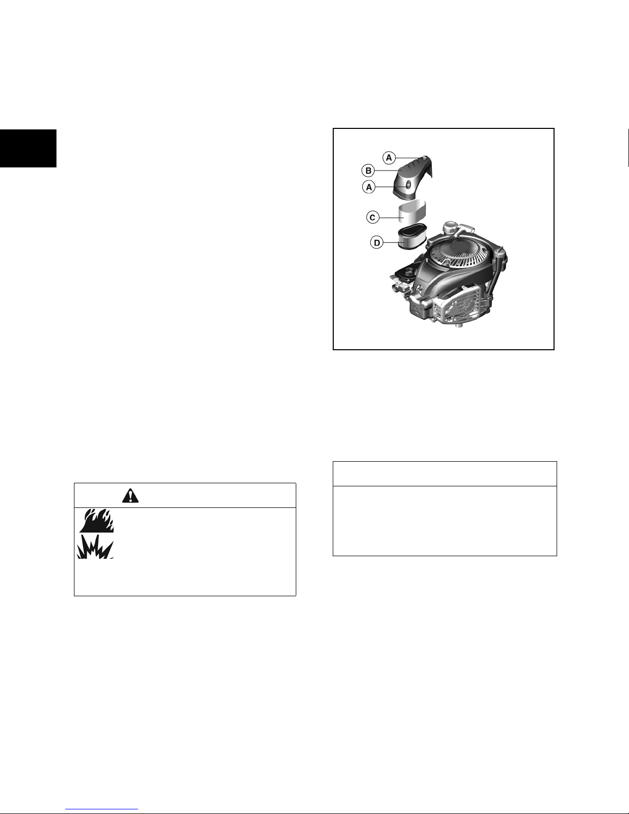
Air Filter
A correctly serviced air filter protects internal
engine parts from airborne dirt and dust. Poor
filter maintenance will allow dirt and dust to be
drawn into the engine, causing wear to the intake
system and contamination of the oil. Dirt in the oil
forms an abrasive mixture which wears down
moving parts.
WAR NING
Fuel and its vapors are extremely flammable and explosive.
Fire or explosion can cause severe
burns or death.
• Never start or run the engine with the air
cleaner assembly or the air filter removed.
NOTE: Do not use pressurized air or solvents to
clean the filter. Pressurized air can damage the
filter and solvents will dissolve the filter.
1. Remove air cleaner cover (A and B,
Figure 1-2). Remove pre-cleaner (C) from
cartridge (D).
Figure 1 - 2
Spark Plug
The spark plug should be replaced every year.
NOTICE
Spark plugs have different thread lengths
and heat ranges. When changing a spark
plug, use only the specified replacement,
otherwise engine damage could occur.
NOTE: In some areas, local law requires using
resistor spark plugs to suppress radio frequency
interference.
1. Disconnect spark plug wire.
2. Remove and inspect spark plug for wear
and damage. Replace spark plug if
electrodes are burned away, or the
porcelain is cracked.
8

3. Do not sand-blast or bead-blast the spark
plug. Clean by scraping or wire brushing,
and then washing in a commercial solvent.
4. Using a wire gage, check and set the gap
(A, Figure 1-3) per Section 12 Specifications.
Figure 1 - 3
5. Re-install spark plug and torque to values
listed in Section 12 - Engine
Specifications.
6. Connect spark plug wire.
Cooling System
WAR NING
Running engines produce heat.
Severe burns can occur on contact.
• Allow muffler, engine cylinder fins, and radiator
to cool before touching.
• Remove accumulated combustibles from muffler area and cylinder area.
Dirt or debris can restrict air flow and cause the
engine to overheat, resulting in poor
performance and reduced engine life. Continued
operation with a clogged cooling system can
cause severe overheating and possible engine
damage. Clean these areas (A, Figure 1-4)
yearly or more often when dust or airborne
debris is present.
1
1
Figure 1 - 4
Charging Battery
1. Clean the battery of all dirt and corrosion.
2. Clean, then lightly grease the terminals.
3. Bring the battery to full charge using a
taper charge (automatically reduces
charge rate).
NOTE: Do not exceed a charge rate of 1/10
ampere for every ampere of battery rating.
Consult the battery manufacturer for maximum
charge recommendations.
NOTE: If the battery gets hot to the touch or is
spitting acid (gassing) excessively, unplug the
charger periodically.
4. With the battery fully charged, check the
specific gravity readings of each cell with a
temperature-compensated Battery
Hydrometer (Figure 1-5). All readings
should be above 1.250 (compensating for
temperature). If the readings vary by
0.050 or if all cells read less than 1.225,
replace the battery.
NOTICE: Do not use water to clean the engine.
Water could contaminate the fuel system. Use a
brush or dry cloth to clean the engine.
9
Figure 1 - 5

1
Combustion Chamber
Remove combustion chamber deposits every
500 hours or whenever the cylinder head is
removed.
With the piston at Top Dead Center (TDC),
scrape deposits from top of piston and upper
bore with a plastic scraper.
Remove the loosened deposits from around the
top ring land area using compressed air or a
shop vacuum and a soft bristle brush.
cylinder. Do not damage bore, top of piston,
cylinder head, or gasket mounting surfaces.
It is not necessary to remove the discoloration
marks on the piston, valves, and/or cylinder
head. These marks are normal and will not affect
engine operation.
1
NOTICE: Use care to prevent debris from
entering the valve lever or oil return cavities in
ENGINE ADJUSTMENTS
Throttle Cable Adjustment
The remote control wire should measure 2.125”
(54mm) when extended outside the casing
(A, Figure 1-6). After installation, the travel (B) of
the remote control wire must be at least 1.375”
(35 mm). If the travel of the remote control wire
does not reach the minimum distance, use the
following procedure to adjust the cable:
1. Loosen casing clamp screw (C).
2. Move throttle lever to FAST position.
3. Move casing in direction of arrow (D) until
slack is removed.
4. Tighten casing clamp screw. Torque to
values listed in Section 12 - Engine
Specifications.
10
Figure 1 - 6
Governor Adjustments
A complete governor system adjustment
includes a static adjustment, engine warm-up,
and top no-load adjustment. Be sure to complete
all steps.
Static Adjustment
1. Loosen nut (A, Figure 1-7) until governor
lever (B) moves freely from governor
crank (C).
2. Move throttle linkage (D) until throttle plate
(E) is wide open.

NOTE: Choke valve (F) closes when opening the
throttle plate.
3. While holding linkage, tighten governor
lever nut. Torque to values listed in
Section 12 - Engine Specifications.
4. Before starting engine, manually actuate
throttle linkage to check for binding.
1
1
Figure 1 - 7
Top No-Load Adjustment
1. Start engine and run at idle speed until it
reaches operating temperature.
2. Place throttle lever (G, Figure 1-8) in FAST
position.
3. Using Tachometer #19200 or #19389 (H),
and Tang Bender #19229 or #19352 (J),
bend spring tang (K) to obtain correct top
no-load RPM.
NOTE: Correct top no-load RPM for each modeltype-trim can be found in the engine replacement
data on Briggs & Stratton websites.
Figure 1 - 8
11

1
1
Adjust Valve Clearance
NOTE: Check valve clearance while the engine
is cold.
1. Insert a narrow gauge such as a
screwdriver, rod, or pencil (A, Figure 1-9)
into the spark plug hole (B) until it touches
the piston (C). Cut away view is shown.
2. Observe the movement of the gauge and
turn the flywheel (D) clockwise past top
dead center on the compression stroke
until the piston has moved down the bore
0.25 in. (6.4 mm).
3. Valve clearance is checked by placing a
feeler gauge (E) between the lever arm
adjusting screw (F) and the valve cap (G).
4. Loosen the adjusting screw nut (H) with a
wrench.
5. Using an allen wrench, turn the adjusting
screw (F) to obtain the correct clearance.
6. Tighten the adjusting screw nut (H) to the
torque values listed in Section 12 - Engine
Specifications.
7. Recheck clearance after tightening nut.
Adjust ReadyStart Choke Link
Perform this adjustment while the engine is cold.
1. Using pliers, bend adjusting loop (A,
Figure 1-10) on choke link (B) until choke
lever gap (C) measures 0.000 - 0.060 in.
(0.000 - 1.52 mm). When properly
adjusted, the choke plate (D) will be fully
closed. Reshape wire to keep it parallel
(E) after adjusting loop.
Figure 1 - 9
12
Figure 1 - 10

Adjust Armature Air Gap
1. Disconnect spark plug boot (A, Figure 1-
11) and secure away from spark plug.
2. Loosen screw (B) and stud (C).
3. Slide armature (D) away from flywheel.
4. Tighten stud to secure armature.
5. Line up flywheel magnets (E) with
armature.
6. Insert a strip of gauge material (F)
(0.006 - 0.014 in. or 0.15 - 0.36 mm)
between flywheel magnet and both legs of
armature.
7. Loosen stud and allow magnet to pull
armature against gauge (G).
8. Tighten fasteners and torque to values
listed in Section 12 - Engine
Specifications.
9. Rotate flywheel to remove gauge.
1
1
Figure 1 - 11
13

1
1
Adjust Alternator Air Gap
1. Remove spark plug.
2. Loosen alternator screws (A, Figure 1-12).
and slide alternator (B) away from
flywheel.
3. Tighten one screw to secure alternator.
4. Line up flywheel magnet (D) with
alternator.
5. Insert a strip of gauge material (C)
(0.006-0.014 in. or 0.15-0.36 mm)
between flywheel magnet and both legs of
alternator.
6. Loosen screw and allow magnet to pull
alternator against gauge.
7. Tighten fasteners and torque to values
listed in Section 12 - Engine
Specifications.
8. Rotate flywheel to remove gauge.
Figure 1 - 12
14
Flywheel Brake
The flywheel brake is part of the safety control
system required for some applications. While
running at the FAST speed position, the flywheel
brake MUST stop the engine within three
seconds when the operator releases the
equipment safety control.
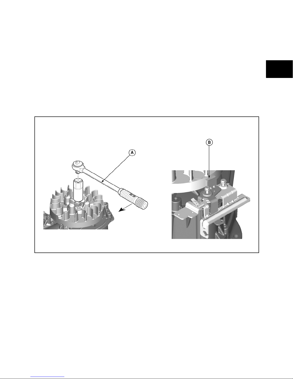
Test Brake Torque
1. Disconnect spark plug wire.
2. Remove static guard/rewind assembly.
3. Unscrew and remove fuel tank.
4. Remove dipstick and oil fill tube.
5. Unscrew and remove blower housing.
6. Using a torque wrench (A, Figure 1-13)
and socket to fit the flywheel nut, turn
flywheel clockwise with brake engaged.
While turning at a steady rate, torque
value should be 26 lb.-in. (3 Nm) or higher.
7. If reading is low, check thickness of brake
pad (B). Replace brake assembly if
thickness is less than 0.090” (2.28mm).
8. If brake pad thickness is acceptable,
adjust control cable to position pad closer
to flywheel when safety control is in RUN
position.Repeat Step 6.
9. Replace brake assembly if correct
adjustment cannot be made.
1
1
Figure 1 - 13
15
1
1
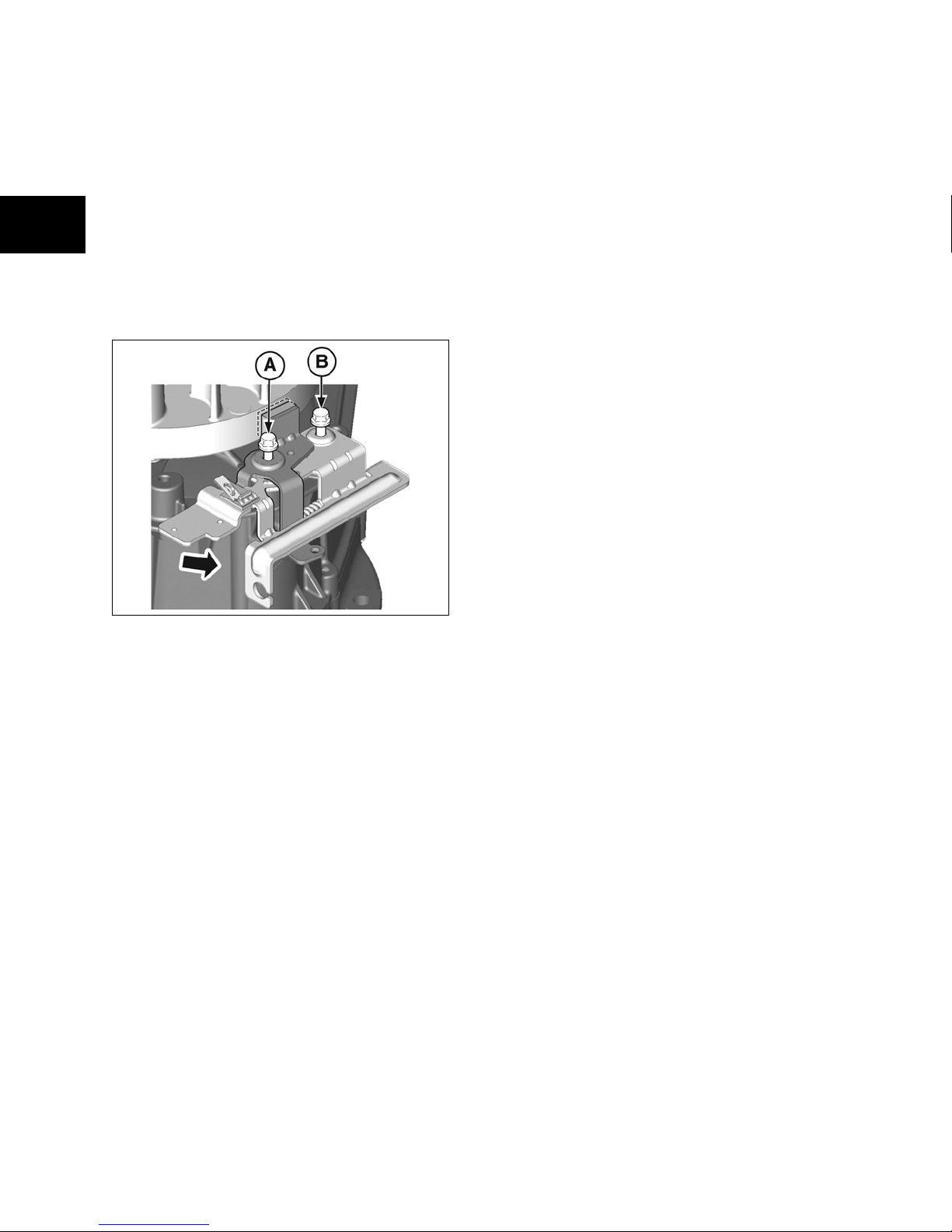
Remove Flywheel Brake
1. Disconnect and remove spring from brake
anchor.
2. Disconnect safety control cable from brake
assembly.
3. Loosen brake screw (A, Figure 1-14) but
do not remove.
4. Rotate bracket to relieve tension on screw
(B) and remove, then remove screw (A).
5. Press stop switch tang to disconnect stop
wire, then remove brake assembly.
6. Disconnect wires on interlock switch, if
equipped.
Figure 1 - 14
Install Flywheel Brake
1. Install stop switch wire and bend end of
wire 90°. Install wires on interlock switch, if
equipped.
2. Install brake assembly on cylinder and
torque mounting screws to values listed in
Section 12 - Engine Specifications.
3. Connect safety control cable and install
brake spring.
4. Actuate brake system to ensure proper
movement, then test brake torque as
previously described.
5. Install blower housing, oil fill tube, dipstick,
fuel tank, and static guard/rewind
assembly. Torque all screws to values
listed in Section 12 - Engine
Specifications.
16

SECTION 2 - TROUBLESHOOTING
SYSTEMS CHECK - - - - - - - - - - - - - - - - - - - - - - - - - - - - - - - - - - - - - - - - - - - - - - - - - - - - - - - - - - - - - - - - - - - - 18
CHECK IGNITION - - - - - - - - - - - - - - - - - - - - - - - - - - - - - - - - - - - - - - - - - - - - - - - - - - - - - - - - - - - - - - - - - - - - - 18
CHECK CARBURETION - - - - - - - - - - - - - - - - - - - - - - - - - - - - - - - - - - - - - - - - - - - - - - - - - - - - - - - - - - - - - - - - 19
CHECK COMPRESSION - - - - - - - - - - - - - - - - - - - - - - - - - - - - - - - - - - - - - - - - - - - - - - - - - - - - - - - - - - - - - - - 19
ELECTRICAL SYSTEMS - - - - - - - - - - - - - - - - - - - - - - - - - - - - - - - - - - - - - - - - - - - - - - - - - - - - - - - - - - - - - - - - 20
EQUIPMENT USED FOR TESTING - - - - - - - - - - - - - - - - - - - - - - - - - - - - - - - - - - - - - - - - - - - - - - - - - - - - - - - - 20
ALTERNATOR TESTING - - - - - - - - - - - - - - - - - - - - - - - - - - - - - - - - - - - - - - - - - - - - - - - - - - - - - - - - - - - - - - - - 21
STARTER MOTOR TESTING- - - - - - - - - - - - - - - - - - - - - - - - - - - - - - - - - - - - - - - - - - - - - - - - - - - - - - - - - - - - - 22
BATTERY TESTING - - - - - - - - - - - - - - - - - - - - - - - - - - - - - - - - - - - - - - - - - - - - - - - - - - - - - - - - - - - - - - - - - - - 23
2
1
17

SYSTEMS CHECK
1
2
Most complaints concerning engine operation
can be classified as one or a combination of the
following:
• Will not start
• Hard starting
• Lack of power
• Runs rough
• Vibration
• Overheating
• High oil consumption
What appears to be a problem with the engine
may actually be the fault of the equipment.
Following is a list of some common engine
symptoms and their relationship to equipment
problems.
No Start - Hard Start
• Loose belt or blade
• Cranking under load
• Misadjusted controls
• Interlock system malfunction
Once equipment sources are ruled out, the
cause for most of these symptoms can be
determined by performing a systems check in the
following order:
1. Ignition
2. Carburetion
3. Compression
This check-up can usually be done in a matter of
minutes and is the quickest and surest method of
determining the cause of such problems.
1) Check Ignition
Engine Stopped
With spark plug installed, attach Ignition Tester
#19368 to spark plug lead and ground the other
end of the tester (Figure 2-1). Pull the starter
rope or activate the electric starter (if equipped).
If spark jumps the tester gap, you may assume
the ignition system is functioning satisfactorily.
Engine Will Not Stop
• Equipment stop switch not functioning
• Engine ground wire damaged or
disconnected
Vibration
• Bent cutter blades
• Loose spindles and couplings
• Bent/broken deck or weldments
• Bent crankshaft
• Loose equipment mounting bolts
• Damaged or worn belts and pulleys
• Out of balance impeller
Power Loss
• Bind or drag in moving parts of
equipment
• Grass build-up under deck
• No lubrication in equipment gear box
• Excessive belt tension
Figure 2 - 1
Engine Running
If engine runs but misses during operation, a
quick check to determine whether the ignition is
at fault can be made by installing Ignition Tester
#19368 between the spark plug lead and spark
plug (Figure 2-2). If spark is good but engine
misses, install a new spark plug.
18

Figure 2 - 2
If spark does not occur, look for:
• Improperly operating interlock system
• Shorted equipment or engine stop switch
wire
• Incorrect armature air gap
• Armature failure
2) Check Carburetion
Before making a carburetion check, be sure the
fuel tank has an ample supply of fresh, clean
gasoline.
Be sure the shutoff valve, if equipped, is open
and fuel flows freely through the fuel line. If fuel
fails to flow or is slow, check for plugged fuel cap
vent, fuel line restriction or plugged fuel filter.
Be sure throttle and choke controls are properly
adjusted.
If engine cranks but will not start, remove and
inspect the spark plug.
If plug is wet, look for:
• Over choking
• Excessively rich fuel mixture
• Water in fuel
• Float needle valve stuck open
• Plugged air cleaner
• Fouled spark plug
If plug is dry, look for:
• Leaking carburetor or intake manifold
gaskets
• Gummy or dirty carburetor, fuel filter, fuel
lines or fuel tank
• Float needle valve stuck closed
• Inoperative fuel pump (if equipped)
• Inoperative fuel shut off solenoid (if
equipped)
A simple check to determine if the fuel is getting
to the combustion chamber through the
carburetor is to remove the spark plug and pour
a small quantity of gasoline through the spark
plug hole. Replace the plug. If the engine fires a
few times and then stops, look for the same
conditions as for a dry plug.
3) Check Compression
Use Leakdown Tester #19545 to check the
sealing capabilities of the compression
components.
Follow the instructions provided with the tester to
perform the leakdown test.
NOTE: Any air leaks at the connections or
fittings of the tester will affect the accuracy of the
test.
Listen for air leaking from the cylinder head
gasket, carburetor, exhaust system, and the
crankcase breather tube.
• Air flowing between the cylinder and
cylinder head indicates that the cylinder
head gasket is leaking.
• Air flowing from the carburetor indicates
air is leaking past the intake valve and
seat.
• Air flowing from the exhaust system
indicates air is leaking past the exhaust
valve and seat.
• Air flowing from the crankcase breather
tube or high oil fill dipstick tube indicates
air is leaking past the piston rings.
Possible Causes for Poor Compression:
• Loose cylinder head bolts
• Blown head gasket
• Burned valves, valve seats and/or loose
valve seats
• Insufficient tappet clearance
• Warped cylinder head
• Warped valve stems
• Worn bore and/or rings
• Broken connecting rod
2
1
19

1
2
ELECTRICAL SYSTEMS
Equipment Used for Testing
Digital Multimeter
A digital multimeter is recommended for all
electrical testing of Briggs & Stratton engines.
The meter can be used to read volts, ohms,
amperes, and to test diodes.
The Fluke® Digital Multimeter #19464 and the
UNI-T® Digital Multimeter #19581 are available
from your Briggs & Stratton source of supply.
NOTICE: The digital multimeters are equipped
with fuses to prevent damage to the meter if the
input limits are exceeded. Check the fuses if the
meter displays a reading of 0.00 when testing
DC Volts output.
Refer to the Fluke® Operator’s Manual for this
procedure. Replacement fuses #19449 for Series
II meters or #19571 for Series III meters are
available from your Briggs & Stratton source of
supply.
The UNI-T® Operator’s Manual lists the fuse
replacement procedure and type of replacement
fuses required.
Figure 2 - 4
Starter Motor Test Fixture
A starter motor test fixture may be made from
1/4” (6mm) steel stock (Figure 2-5).
1. Drill two 3/8” (10mm) holes for starter
mounting bracket (B).
2. Using same spacing, drill an additional
3/8” (10mm) hole (A) for alternate starter
mounting position.
3. Using a #7 bit, drill two holes for mounting
Tachometer #19200. Tap the holes for 1/
4-20 NC screws (C).
DC Shunt
The Fluke® meter will withstand DC input of 1020 amps for up to 30 seconds.
The UNI-T® meter will withstand DC input of 10
amps for up to 10 seconds.
When checking DC output on 10 and 16 amp
regulated systems, the DC Shunt #19468
(Figure 2-3) is required to avoid blowing a fuse in
either of the meters.
Figure 2 - 3
Tachometer
Tachometers #19200 (A) or #19389 (B, Figure 2-
4) are available from your Briggs & Stratton
source of supply.
Figure 2 - 5
Other Equipment
A growler or armature tester (checks armature
for continuity, shorts, and opens) is available
from an Automobile Diagnostic Service supplier.
Also, a known good 12 Volt battery is required
when testing starting systems or alternators.
20
 Loading...