

Page 1
Briggs & Sfr?Je*©iii!
mo AND MA^NTlfsiAWCl
INSTRUCTIONS
MODELS
146400 to 146457
170400 to 170457
190400 to 190457
IN THE INTEREST OF SAFETY, 00 NOT RUN ENGINE AT EXCESSIVE SPEEDS
Operating an engine at excessive speeds increases the hazard of personal injury. DO NOT TAMPER WITH PARTS WHICH MAY
INCREASE THE GOVERNED SPEED.
For rotary lawnmower safety, USA Standard Safety Specifications for Power Lawn Mowers specify a maximum blade tip speed
of 19,000 feet per minute, primarily to reduce the hazard from thrown objects.
Rotary lawnmower manufacturers select the governed top speed of the engine based on the length and design of the cutter
blade and design of other mower parts.
All rotary lawnmowers should be checked for conformance to the USA Standard Safety Specifications for Power Lawn Mowers
on blade tip speed, if the engine is repaired or replaced, or if mower parts are changed.
Dirt and grass clippings, or other debris, in cooling fins or governor parts can affect engine speed. See cleaning instruc
tions in Section 3.
TO PREVENT ACCIDENTAL STARTING always remove the spark plug before working on the engine or equipment driven by the
engine or remove cable from spark plug and insert terminal in V-notch in cylinder head cover.
DO NOT RUN THE ENGINE IN AN ENCLOSED AREA. Exhaust gases contain carbon monoxide, an odorless and deadly poison.
DO NOT FILL GASOLINE TANK WHILE ENGINE IS RUNNING. Spilling gasoline on a hot engine may cause a fire or explosion.
CAUTIOIM
Section
1
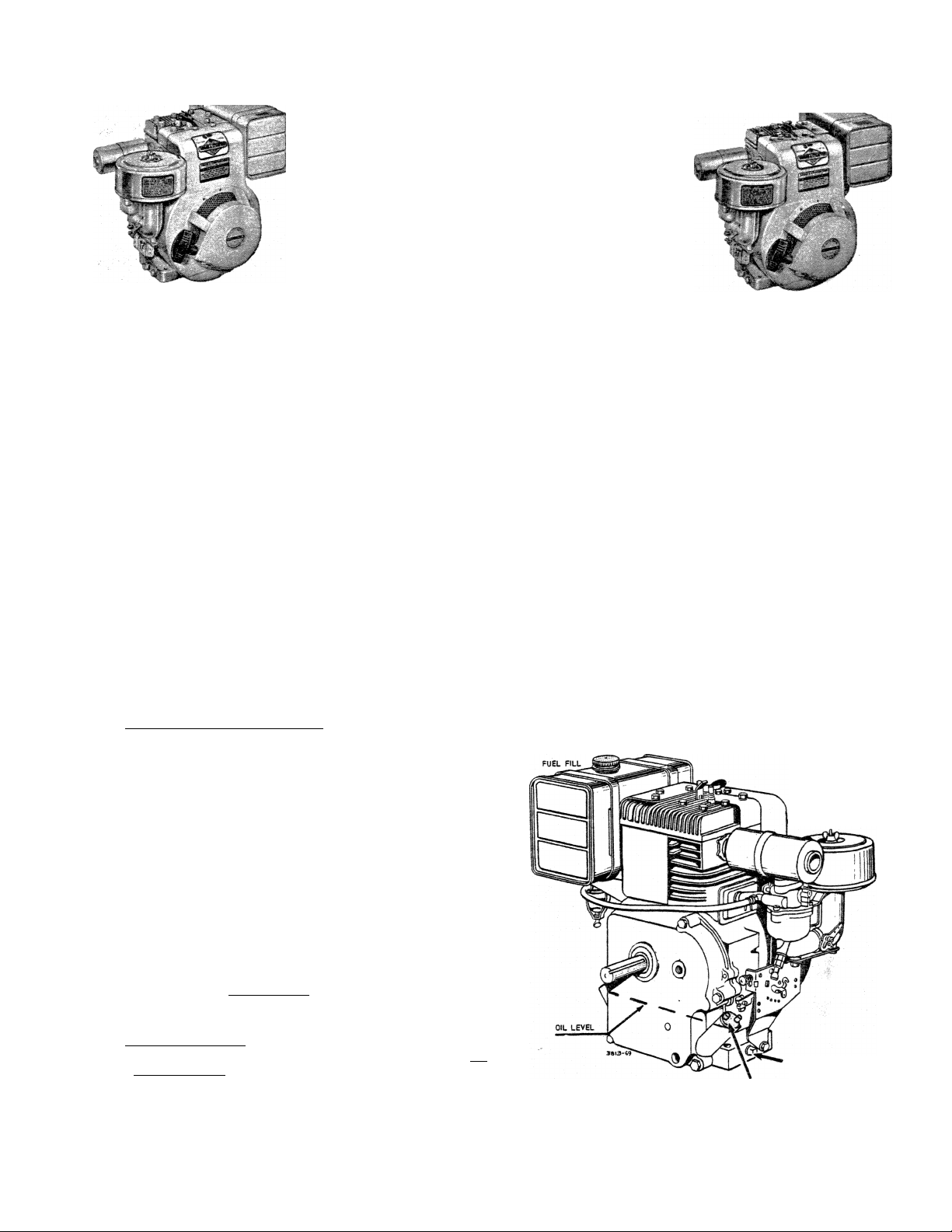
FILL CRANKCASE WITH OIL-Use a high quality de
tergent oil classified "For Service SCorSD or MS".
©
Nothing should be added to the recommended oil.
Summer Winter
(Above 40® F.) (Under 40® f.)
Use SAE 30 Use SAE 5W-20 or SAE 5W-30
If not available. If not available.
Use SAE 10W-30 Use SAE 10W or SAE 10W-30
CAP 1 oW-40 Below 0® F,
DIRECTIONS: Place the engine level. FILL THE OIL
SUMP TO OVERFLOWING or to the FULL mark on dip
stick. Pour slowly. Capacity 2-3/4 pints.
EXTENDED OIL FILL (Optional). Remove cap and dip
stick and fill to full mark on dipstick. When checking
oil level push dipstick assembly firmly but slowly until
cap bottoms on tube. Do not overfill. Dipstick assem
bly must be pushed fully into tube at all times when
engine is operating.
FILL FUEL TANK — Use clean, fresh, lead-free or
leaded "regular" grade automotive gasoline. Fill
©
tank completely !
DO NOT MIX OIL WITH GASOLINE.
BEFORE STARTING
Use SAE 10W or SAE 10W-30
Diluted 10% with Kerosene
READ THE OPERATING INSTRUCTIONS OF
THE EQUIPMENT THIS ENGINE POWERS
AIR CLEANER
OIL DRAIN PLUG
OIL FILLER PLUG
FORM NO. 270367-71
PRINTED !N U.S.A.
BRIGGS & STRATTON CORP.
Milwaukee, Wisconsin 53201
Page 2
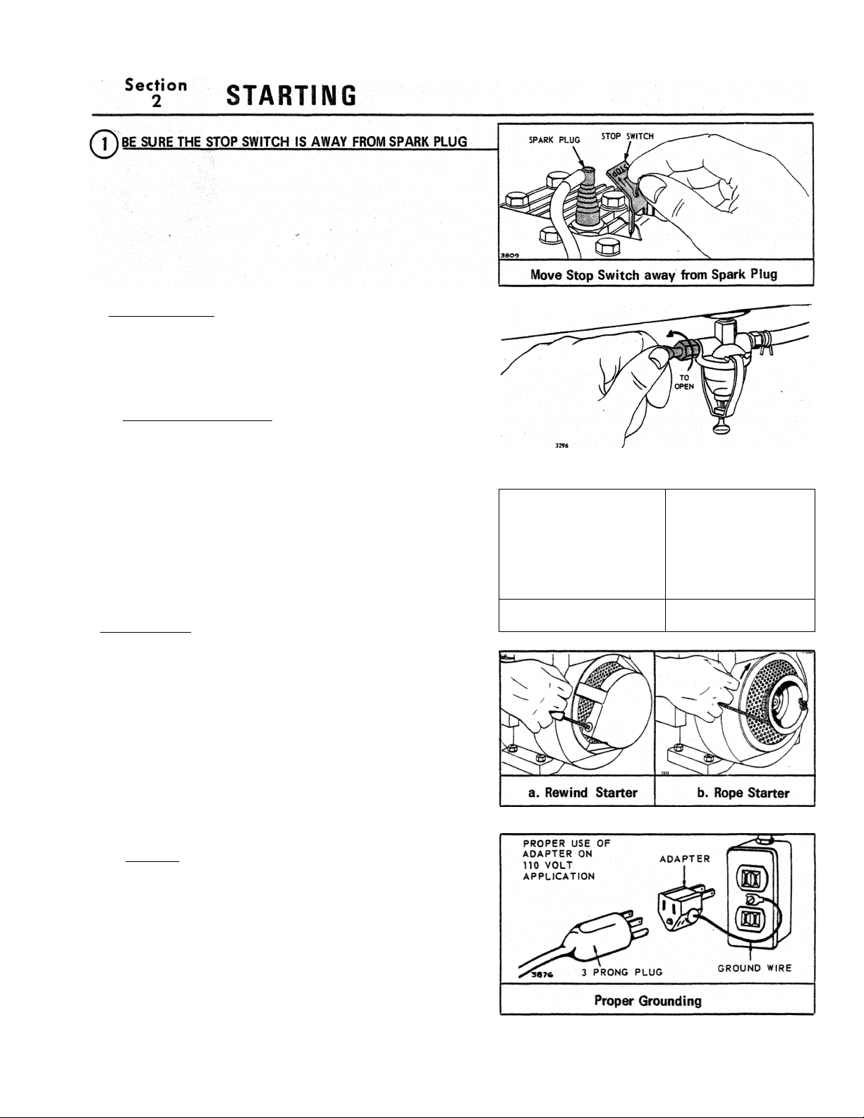
(T) OPEN FUEL VALVE
CHOKE THE CARBURETOR
a. (Vlanual Type
Move lever in direction of arrow to fully closed choke
position. Set governor control in normal operating po
sition.
b. Choke-A-Matic
Move lever to 'Tull Choke" or "Start" position.
Mote: This should fully close choke on carburetor. If
it does not, remote control must be re-adjusted. See
"Choke-A-Matic Carburetor" Adjustments, Section 4.
Note: A warm engine requires less choking than a
cold engine.
(j^START ENGINE
a. Rewind Starter Grasp starter grip as Illustrated and
pull out cord two to three feet. Repeat If necessary
with choke opened slightly. When engine starts open
choke gradually.
Opening Fuel Valve
a.- Manual Type
b. Choke-A-Matic
b. Rope Starter Wind the starter rope around the pulley
in direction shown by arrow. Pull the rope with a
quick full arm stroke. Repeat if necessary with choke
opened slightly. When engine starts open choke grad
ually.
c. Electric. Starter Press starter button on powered
equipment. When engine starts open choke gradually.
CAUTION: The 110 volt electric starter is equipped
with a three prong plug for your safety. If a longer
extension cord is used it should also have three-prong
and three hole plugs. If the outlet or receptacle is the
two-hole type, an adapter must be used. To get the
proper grounding, fasten the ground lead on the adapter
to something electrically grounded, such as the metal
box on the end of a grounded metal conduit.
FORM NO. 270367-71
Page 3
Section
2
SPECIAL LOW TEMPERATURE STARTING PROCEDURE 1. Turn needle valve on carburetor 1/8 turn counterclock
wise from normal summer adjustment. Note: If fuel drips out of carburetor while trying to start engine, the engine
is over choked. Puli starter several times or push starter button with choke open. 2. Be sure to use the proper
weight of oil for the air temperature expected. 3. Disconnect all external loads. Any V-belt drives must be
removed or loosened so that the belts are standing still for satisfactory operation below freezing. Starter, motor
and battery are designed to start the engine only. 4. Keep battery and engine warm if possible. If it is not
possible to keep the entire unit warm, there is a big advantage in keeping the battery warm until it is required
for starting. A warm battery has much more starting capacity than a cold battery.
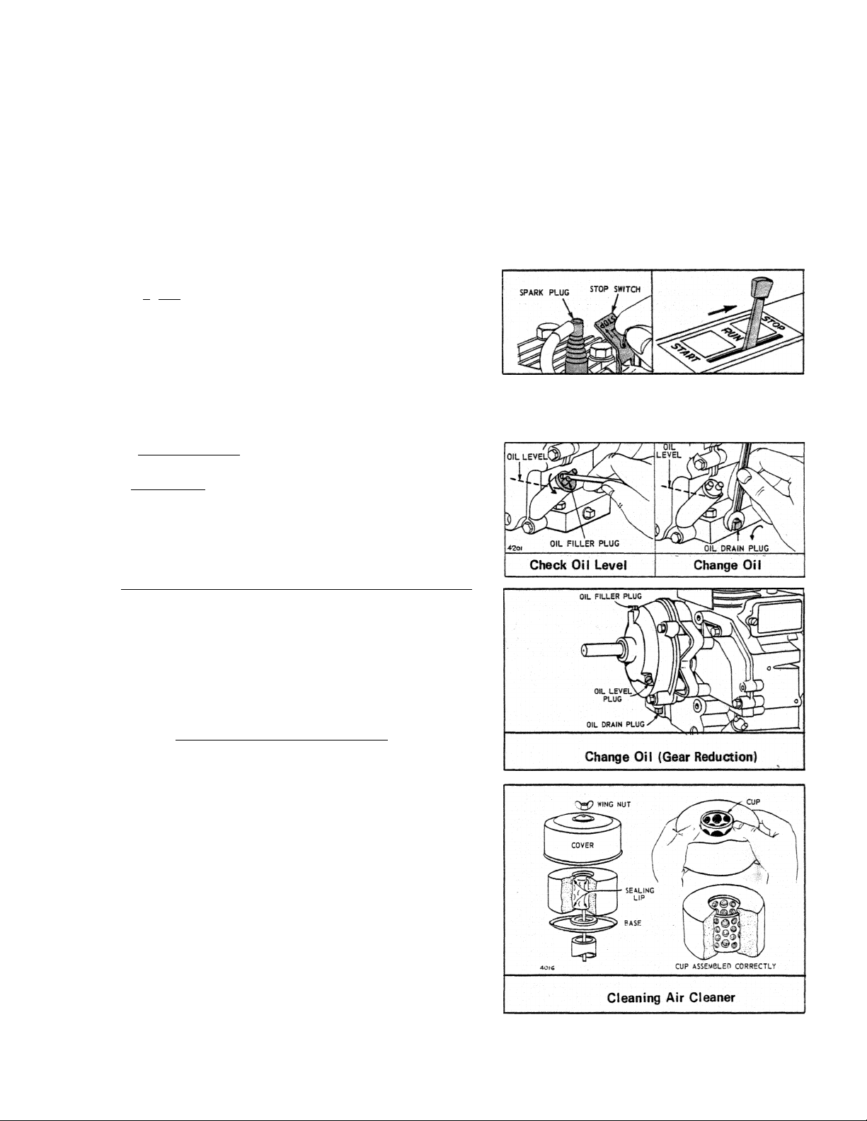
$TQP.EMSIN£,
©
a. Manual Choke - Push the stop switch against end
of spark plug.
b. Choke-A-Matic - Move control lever to "Stop" po
sition.
STARTING (cont’d)
Section
3
CHECK OIL LEVEl
operation. BE SURE OIL LEVEL IS MAINTAINED.
©
^2JCHANGE OIL after first 5 hours of operation. There
inafter change oil every 25 hours of operation. Remove
oil drain plug and drain oil while engine is warm. Re
place drain plug. Remove oil filler plug or cap and
refill with new oil of proper grade. Replace oil filler
-’- plug or cap. -
(^CHANGE OIL (GEAR REDUCTION oDtionall hv rBmovino
in oil level plug. Remove drain plug in bottom of gear
case cover and drain oil every 100 hours of operation.
To refill, remove oil check plug and oil filler plug and
pour oil (same grade as. used in crankcase) into filler
hole until It runs out level check hole. Replace both
plugs. Oil filler plug has a vent hole and must be in
stalled on top of gear case cover.
(^SERVICE AIR CLEANER REGULARLY - Clean element
"Oil-Foam" ® Type
MAINTENANCE
___
r£giAady^-,aflFir.,,Rar:h 5 hrmrs«.nt.
25 hours — more often under dirty conditions.
1. Remove wing nut and cover.
2. Lift off foam element from base.
3. Push down foam element as shown, and pull out air
cleaner cup.
4. A~Wash foam element in kerosene or liquid deter
gent and water to remove dirt.
B - Wrap foam in cloth and squeeze dry.
C —Saturate foam in engine oil. Squeeze to remove
excess oil.
D —Put air cleaner cup inside element. Be sure
sealing lip is over end of cup (top and bottom).
5. Reassemble parts as shown. Screw wing nut down
tight.
Page 4
Section
3
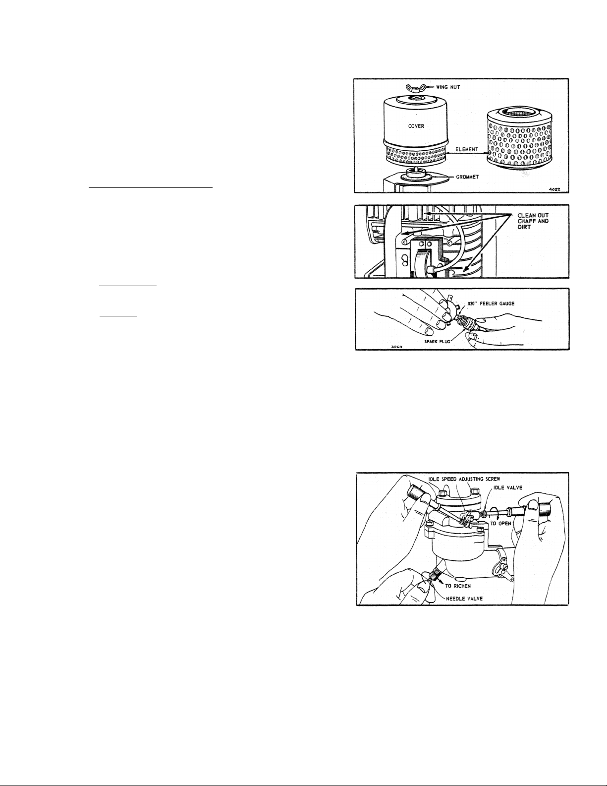
Dry Element Type
To clean - tap element (top or bottom) on flat surface
or wash in non-sudsing detergent and flush from inside
until water is clear. After washing, air dry thoroughly
before using. DO NOT OIL.
(?)CLEA1M CQQLUMG SYSTEM - Grass or chaff may clog
^"^cooling system after prolonged service in cutting tall
dry grasses or hay. Continued operation with a clog
ged cooling system causes severe overheating and
possible engine damage. Remove blower housing and
clean regularly.
SPARK PLUG-Clean and reset gap at .030" every 100
hours of operation.
CAUTION: Blast cleaning of spark plugs in machines
that use abrasive grit is not recommended. Spark plugs
should be cleaned by scraping or wire brushing and
washing with a commercial solvent or gasoline.
MAINTENANCE (cont’d)
CLEAN COMBUSTION CHAMBER every 100-300 hours of operation. The use of regular automotive fuels and con
stant speed and toad operation, often result in a gradual build-up of tetraethyl lead deposits in the combustion
chamber. Remove cylinder head. Scrape and wire brush the lead and carbon deposits from cylinder head,* top of
piston and around valves. Use a soft brush or compressed air to remove loose deposits.
Reassemble cylinder head, gasket, cover and turn down screws finger tight Use the three longer screws around
the exhaust valve. Using a socket wrench with a 6" handle, turn all screws an additional 1/4 turn (150-175
torque). BE SURE TO TIGHTEN head mounting screws in a staggered sequence.
Section
4
CARBURETOR ADJUSTMENTS
Minor carburetor adjustment may be required to com
pensate for differences in fuel, temperature, altitude
and load.
To Adjust Carburetor Turn needle valve clockwise
until it just closes. Caution: Valve may be damaged
by turning it in too far.
Now open needle valve 1-1/8 turns counterclockwise.
Close idle valve in same manner and open 1-1/8 turns.
This initial • adjustment will permit the engine to be
started and warmed up prior to final adjustment.
Final Adjustment: Turn needle valve in until engine misses (lean mixture) then turn it out past smooth operating
point until engine runs unevenly (rich mixture): Now turn needle valve to the mid-point between rich and lean so
the engine runs smoothly. Hold throttle at idle position and set idle speed adjusting screw until fast Idle is
obtained (1750 RPM). Hold throttle in idle position and turn idle valve in (lean) and out (rich) until engine idles
smoothly. Then reset idle speed adjusting screw so that engine idles at 1750 RPM. Release throttle—engine
should accelerate without hesitation or sputtering. If engine does not accelerate properly, the carburetor should
be re-adjusted to a slightly richer mixture.
ADJUSTiVlENTS
Page 5
Section
4
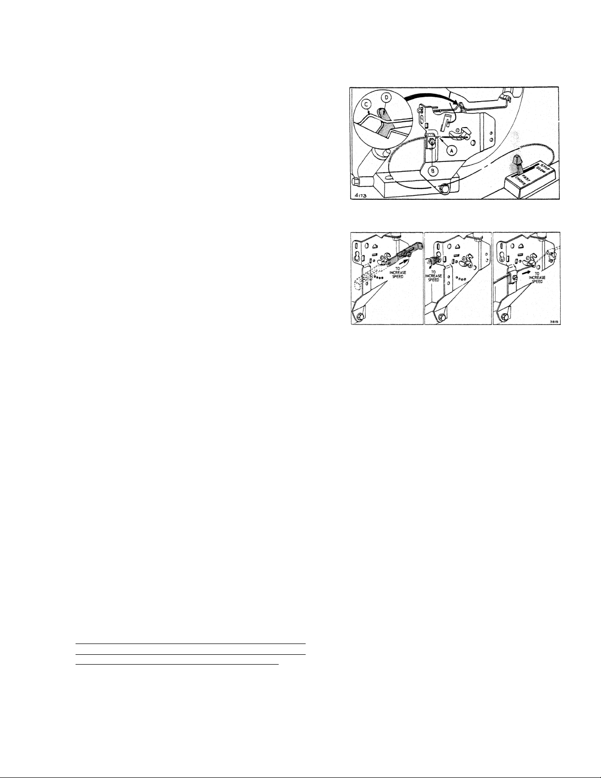
CHOKE-A-iVlATIC CARBURETOR CONTROL
ADJUSTMENTS
Proper choke and stop switch operation is dependent
upon proper adjustment of remote control on the pow
ered equipment.
To Check Operation of Choke-A-Matic Controls:
a. Remove air cleaner.
b. Move remote control lever to "Choke" position. The
carburetor choke should be closed.
c. Move remote control to "Stop" position. Lever
should make good contact with stop switch.
To Adjust:
Place remote control lever on equipment in FAST (high
speed) position. Loosen control casing clamp screw
"B". Move control casing "A" and wire until lever
"D" touches choke operating link at "C". Tighten
casing clamp screw "B". Replace air cleaner.
SPEED CONTROL ADJUSTMENTS
The recommended operating speed range is 1800 to
3600 RPM. The standard speed setting (no load) Is
3600 RPM. Idle speed is 1750 RPM.
Refer to illustration. Select the control on your engine.
To increase engine speed move control in direction
shown by arrow.
ADJUSTMENTS (cont’d)
Section
5
ENGINE DESIGN - Your engine is 4 cycle, single cylinder and L-head. It is air cooled.
Bore
Stroke
Displacement
Horsepower
Torque (Ft. Lbs.)
The horsepower ratings listed above are established
in accordance with the Society of Automotive Engi
neers Test Code-J607. For practical operation, the
horsepower loading should not exceed 85% of these
ratings. Engine power will decrease 314% for each
1,000 feet above sea level and 1 % for each 10° above
60° F.
Spark Plug Type A.C. Autolite Champion
Short Plug CS-45 A7N CJ-8
Long Plug GC-46
Spark Plug Gap...............................
Ignition Point Gap
Intake Valve Clearance . . . .
Exhaust Valve Clearance
GENERAL INFORMATION
MODEL SERIES
146400 to 146457
2-3/4"
2-3/8"
14.11 cu. in.
6.0 H.P. max. @ 3600 RPM
9.25 max. @ 2900 RPM
TUNE-UP SPECIFICATIONS
A71
...........................
.................
J-8
.030'
.020^
005" -.007'
-.011'
.009"
MODEL SERIES
170400 to 170457
16.79 cu. in.
7.0 H.P. max. @ 3600 RPM
11.0 max. @ 2600 RPM
STORAGE INSTRUCTIONS
Engines to be stored over 30 days should be complete
ly drained of fuel to prevent gum deposits forming on
essential carburetor parts, fuel filter, fuel lines and
tank.
a. Drain fuel tank completely and clean fuel filter.
(See Section 3).
b. Operate engine until gasoline in carburetor is com
pletely consumed.
c. While engine is still warm, drain oil from crankcase.
Refill with fresh oil.
d. Remove spark plug, pour one ounce (2 or 3 table
spoons) of SAE-30 oil into cylinder and crank slow
ly to distribute oil. Replace spark plug.
e. Clean dirt and chaff from cylinder head fins and
blower housing. (See Section 3).
3"
2-3/8"
MODEL SERIES
190400 to 190457
3"
2-3/4"
19.44 cu. in.
8.0 H.P. max. @ 3600 RPM
12.7 max. @ 2500 RPM
Page 6
Section
6
SERVICE & REPAIR INFORMATION
If service or repair is needed, contact- an Authorized
Briggs 8* Stratton Service Center. To serve you prompt
ly and efficiently, the Service Center will need the
model, type and code number on your engine. (See
Section 7).
Each Authorized Service Center carries a stock of
original Briggs & Stratton repair parts and is equipped
With special service tools. Trained mechanics assure
expert repair service on all Briggs & Stratton engines.
Your nearest service center is
fisted in the 'Yellow Pages'
under "Engines, Gasoline" or
"Gasoline Engines". He is one
of over 13,000 authorized deal
ers available to serve you.
WARRANTY
BRIGGS & STRATTON ENGINE WARRANTY
For ONE YEAR from purchase date, Briggs & Stratton Corp. will replace for the original purchaser, FREE
OF CHARGE, any part, or parts, found upon examination by any Factory Authorized Service Center, or
by the Factory at Milwaukee, Wisconsin, to be DEFECTIVE IN MATERIAL AND/OR WORKMANSHIP.
All transportation charges on parts submitted for replacement under this Warranty must be borne by
purchaser.
There is no other Warranty express or implied. Briggs & Stratton Corp. shall in no event be liable for
FOR REPAIRS AND SERVICE CONTACT
THE DEALER DISPLAYING THIS SIGN
SAVE THIS SECTION FOR YOUR RECORD
BRIGGS & STRATTON CORP.
V.
V. R. SHIELY
NOTE: The Briggs & Stratton Engine Warranty does not cover breakage of parts or damage to parts due to abuse or
failure to follow the recommended maintenance procedures. The warranty also excludes any accessories, controls
or equipment which are not manufactured by Briggs & Stratton Corporation.
If warranty service is needed contact your nearest Authorized Service Center. For Prompt Attention your center
will need to know the engine model, type and code number, the trouble experienced and the total number of hours
the engine has run. If you differ with the decision of a Service Center on a warranty claim, ask the Service Center
to submit all supporting facts to the Factory for review. If the Factory decides that your claim is justified, you
will be fully reimbursed for those items accepted as defective.
FILL IN THE REQUIRED INFORMATION FOR YOUR RECORD:
(See Decal on Blower Housing for Model, Type and Code Number)
Engine Model No.
Dealer Purchased From
Type of Equipment______
Name or Trademark of Equipment Manufacturer
3RKSGS & STRATTON ENGINES ARE MADE UNDER ONE OR MORE OF THE FOLLOWING PATENTS;
2,669,322 2,796,453 3,114,851 3,149,618 3,194,224 3,252.449 DESIGN
2,693,789 2,999,491 3,118,433 3,165,094 3,236,937 3,276.439 D-191,806 D-196,017 0-197,175 0-213,476
2,693,791 2,999,562 3,144.097 3,168,936 3,242.741 3,378,099 OTHER PATENTS PENDING
____________________________
Type No. ______________________Code No.
3,415,237
PRESIDENT
_____________
Date
_________
 Loading...